| Issue |
A&A
Volume 623, March 2019
|
|
|---|---|---|
| Article Number | A68 | |
| Number of page(s) | 83 | |
| Section | Interstellar and circumstellar matter | |
| DOI | https://doi.org/10.1051/0004-6361/201834467 | |
| Published online | 08 March 2019 | |
Small-scale physical and chemical structure of diffuse and translucent molecular clouds along the line of sight to Sgr B2
1
Max-Planck-Institut für Radioastronomie,
Auf dem Hügel 69,
53121
Bonn,
Germany
e-mail: vthiel@mpifr-bonn.mpg.de
2
INAF-Istituto di Radioastronomia, and Italian ALMA Regional Centre,
Via P. Gobetti 101,
40129
Bologna,
Italy
3
Laboratoire d’Astrophysique de Bordeaux, Université de Bordeaux, CNRS, B18N, Allée Geoffroy Saint-Hilaire,
33615
Pessac,
France
4
I. Physikalisches Institut, Universität zu Köln,
Zülpicher Str. 77,
50937
Köln,
Germany
5
Departments of Chemistry and Astronomy, University of Virginia,
Charlottesville,
VA
22904,
USA
Received:
19
October
2018
Accepted:
3
January
2019
Context. The diffuse and translucent molecular clouds traced in absorption along the line of sight to strong background sources have so far been investigated mainly in the spectral domain because of limited angular resolution or small sizes of the background sources.
Aims. We aim to resolve and investigate the spatial structure of molecular clouds traced by several molecules detected in absorption along the line of sight to Sgr B2(N).
Methods. We have used spectral line data from the EMoCA survey performed with the Atacama Large Millimeter/submillimeter Array (ALMA), taking advantage of its high sensitivity and angular resolution. The velocity structure across the field of view is investigated by automatically fitting synthetic spectra to the detected absorption features, which allows us to decompose them into individual clouds located in the Galactic centre (GC) region and in spiral arms along the line of sight. We compute opacity maps for all detected molecules. We investigated the spatial and kinematical structure of the individual clouds with statistical methods and perform a principal component analysis to search for correlations between the detected molecules. To investigate the nature of the molecular clouds along the line of sight to Sgr B2, we also used archival Mopra data.
Results. We identify, on the basis of c-C3H2, 15 main velocity components along the line of sight to Sgr B2(N) and several components associated with the envelope of Sgr B2 itself. The c-C3H2 column densities reveal two categories of clouds. Clouds in Category I (3 kpc arm, 4 kpc arm, and some GC clouds) have smaller c-C3H2 column densities, smaller linewidths, and smaller widths of their column density PDFs than clouds in Category II (Scutum arm, Sgr arm, and other GC clouds). We derive opacity maps for the following molecules: c-C3H2, H13CO+, 13CO, HNC and its isotopologue HN13C, HC15N, CS and its isotopologues C34S and 13CS, SiO, SO, and CH3OH. These maps reveal that most molecules trace relatively homogeneous structures that are more extended than the field of view defined by the background continuum emission (about 15′′, that is 0.08–0.6 pc depending on the distance). SO and SiO show more complex structures with smaller clumps of size ~5–8′′. Our analysis suggests that the driving of the turbulence is mainly solenoidal in the investigated clouds.
Conclusions. On the basis of HCO+, we conclude that most line-of-sight clouds towards Sgr B2 are translucent, including all clouds where complex organic molecules were recently detected. We also conclude that CCH and CH are good probes of H2 in both diffuse and translucent clouds, while HCO+ and c-C3H2 in translucent clouds depart from the correlations with H2 found in diffuse clouds.
Key words: ISM: molecules / ISM: kinematics and dynamics / ISM: structure / ISM: clouds / astrochemistry / ISM: individual objects: Sgr B2(N)
© V. Thiel et al. 2019
 Open Access article, published by EDP Sciences, under the terms of the Creative Commons Attribution License (http://creativecommons.org/licenses/by/4.0), which permits unrestricted use, distribution, and reproduction in any medium, provided the original work is properly cited.
Open Access funding provided by Max Planck Society.
1 Introduction
Molecular clouds can be categorised based on their physical conditions into dense, translucent, and diffuse molecular clouds (Snow & McCall 2006, and references therein). The boundaries between the three different phases are loose. Dense molecular clouds are mostly protected from UV radiation which can destroy molecules, while diffuse molecular clouds are more exposed to this radiation which often results in a lower molecular fraction of hydrogen and lower abundances of molecules. Translucent molecular clouds are the transition regions between dense and diffuse molecular clouds, not completely shielded against UV radiation. Molecular clouds are usually a mixture of all these three types. The kinetic temperature is between about 30 and 100 K in diffuse molecular clouds, higher than about 15 K in translucent clouds, and between about 10 and 50 K in dense clouds. The typical hydrogen densities are 100− 500, 500− 5000 and > 104 cm−3, respectively (Snow & McCall 2006, and references therein).
Performing absorption studies in the direction of strong background sources offers the opportunity to study the chemical and physical structure of diffuse and translucent molecular clouds along the line of sight. Diffuse molecular clouds make up a large part of the interstellar medium in our galaxy and in other spiral galaxies (e.g. Pety et al. 2013). Their extended structures are thought to be the main component of interarm regions in spiral galaxies (Sawada et al. 2012). A thick diffuse disk may be present in spiral galaxies, as detected in M51 (Pety et al. 2013). In addition, diffuse and translucent molecular clouds form the envelopes of giant molecular clouds (GMCs) in which star formation occurs. Hence, diffuse and translucent molecular clouds play an important role for the interaction between stars and the surrounding gas (e.g. Arnett 1971).
Due to the low densities in diffuse and translucent molecular clouds the excitation temperature of most molecular transitions is close to the temperature of the cosmic microwave background (CMB) radiation, that is 2.73 K (Greaves et al. 1992). Rotational lines are thus sub-thermally excited, very weak, and difficult to detect in emission.
The GMC Sagittarius B2 (Sgr B2) emits strong continuum radiation that can be used as an extended background source to investigate the spatial structure of the diffuse and translucent clouds located along the line of sight. Sgr B2 is located near the Galactic centre (GC) with a projected distance of about 100 pc. The GC has a distance of 8.34 ± 0.16 kpc to the Sun (Reid et al. 2014). The diameter of Sgr B2 is about 40 pc and its mass is about 107 M⊙ (Lis & Goldsmith 1990). Here, we focus on the dense molecular core Sgr B2(N) that contains several H II regions (Gaume et al. 1995)as well as several hot molecular cores (Bonfand et al. 2017; Sánchez-Monge et al. 2017). The continuum emission of Sgr B2(N) in the millimetre wavelength range consists of free–free radiation and thermal dust emission (e.g. Liu & Snyder 1999).
In the past, several molecular absorption studies along the line of sight to Sgr B2(N) and Sgr B2(M) were made using single-dish telescopes (e.g. Greaves & Williams 1994; Neufeld et al. 2000; Polehampton et al. 2005; Hieret 2005; Lis et al. 2010; Monje et al. 2011; Corby et al. 2018). The profiles of the detected absorption features were modelled to investigate the molecular content of the material along the line of sight. The angular resolution of these previous studies was not high enough to resolve the continuum structure of Sgr B2(N). For instance, Corby et al. (2018) investigated simple molecules along the line of sight to Sgr B2 using the Green Bank Telescope. Their data covered the frequency range between 1 and 50 GHz with a resolution between 13′ and 15′′. Corby et al. (2015) performed a spectral survey of Sgr B2 with the Australia Telescope Compact Array (ATCA) between 30 and 50 GHz with an angular resolution of 5–10′′ that starts to resolve the continuum emission of Sgr B2(N). They reported variations in the column densities of several molecules seen in absorption across the field of view of their observations but they did not have enough resolution elements to perform a detailed study of the spatial structure of the clouds seen in absorption along the line of sight. Mills et al. (2018) also used the ATCA between 23 and 37 GHz to observe Sgr B2(N) with an angular resolution of 3′′ in ammonia and methanol, which they detect mainly in emission. They focused their analysis on Sgr B2(N) itself and its hot cores.
We use the EMoCA (Exploring Molecular Complexity with ALMA) survey for our analysis. The aim of the survey is to explore and expand our knowledge of the chemical complexity of the interstellar medium (Belloche et al. 2016). This survey was performed towards Sgr B2(N) with the Atacama Large Millimeter/submillimeter Array (ALMA). The angular resolution of this survey is high enough to resolve the continuum emission of Sgr B2(N) (see Fig. 1). Hence, we can investigate absorption lines at positions where the continuum is still strong enough but which are sufficiently far away from the hot cores towards which absorption features are blended with numerous emission lines. The survey was carried out in the 3 mm wavelength range (covering frequencies from 84.1 to 114.4 GHz). Many important as well as abundant molecular species have transitions in this frequency regime that are suitable for absorption studies. Therefore, this unbiased line survey provides an excellent opportunity to study structures on sub-parsec scales not only in Sgr B2 itself, but also along the whole 8 kpc long line of sight to the Galactic centre. The line of sight to Sgr B2 passes through the Sagittarius, Scutum, 3 kpc, and 4 kpc arms as well as the Galactic centre (GC) clouds up to a distance of about 2 kpc from the GC (e.g. Greaves & Williams 1994; Menten et al. 2011, see Fig. 2).
In this paper we investigate the spatial structure of the molecular clouds traced by several molecules detected in absorption along the line of sight to Sgr B2 at much better angular resolution, namely 1.′′ 6. In Sect. 2 we briefly describe the dataset we used for this work. The different techniques we adopted to analyse the data are presented in Sect 3. We present the results in Sect. 4 and discuss them in Sect. 5. We give a summary in Sect. 6.
 |
Fig. 1 ALMA continuum map of Sgr B2(N) at 85 GHz. The black contour lines show the flux density levels at 3σ, 6σ, 12σ, and 24σ and the dotted ones mark −3σ, with σ the rms noise level of 5.4 mJy beam−1. The black crosses mark the positions of the hot cores Sgr B2(N1) and Sgr B2(N2), the white cross the phase centre (EQ J2000: 17h47m19.87s, −28°22′16′′), and the white triangles the ultra compact HII region K4 and the peak in the shell of the HII region K6 (Gaume et al. 1995). The white ellipse in the lower right corner is the synthesised beam. The white contour encloses the region selected for the analysis of the absorption features, for the particular case of ortho c-C3 H2. The pixel size in this image is 0.′′3. |
 |
Fig. 2 Sketch of the Milky Way and the spiral arms along the line of sight to Sgr B2 (based on Greaves & Williams 1994). The velocity ranges of the diffuse and translucent clouds are indicated in km s−1. |
2 Observations
We analysedthe absorption lines detected in the EMoCA survey (Belloche et al. 2016). This spectral line survey was observed with ALMA in Cycles 0 and 1. It was pointed towards Sgr B2(N) with the phase centre located half way between the two main hot cores N1 and N2 at EQ J2000: 17h 47m19.87s, −28°22′16′′ (see Fig. 1). The survey covers the frequency range from 84.1 to 114.4 GHz with a spectral resolution of 488 kHz (1.7 to 1.3 km s−1) at a median angular resolution of 1.′′6. The median largest angular scale is 21.′′4. The average noise level is~3 mJy beam−1 per channel.Details about the calibration and deconvolution of the data are reported in Belloche et al. (2016).
We also analyse the emission lines of the molecules HCO+, HNC, CS, and 13CO detected in the 3 mm imaging spectral survey of Sgr B2 performed by Jones et al. (2008). The observations were carried out with the 22 m Mopra Millimetre Telescope in June 2006 in on-the-fly mode, covering an area of 5′ by 5′ centred on the J2000 equatorial position 17h 47m19.8s, −28°22′17′′ which is close to Sgr B2(N). The survey covers the full frequency range between 82 and 114 GHz with a spectral resolution of 2.2 MHz (6.4 km s−1 at 100 GHz). Additional narrow-band spectra with a high resolution of 33 kHz (0.10 km s−1 at 100 GHz) were also taken. The angular resolution of the data is about 36′′ and the RMS noise level of the broad-band spectra in main-beam temperature scale is 0.12–0.42 K depending on the frequency.
3 Methods
3.1 Selected data sample
To have enough sensitivity, we analyse the absorption features towards positions where the continuum emission is brighter than four times the RMS noise level. The noise level is derived from a Gaussian fit to the flux density distribution of all pixels in the continuum map not corrected for primary beam attenuation. For this, we use the command go noise in the GILDAS package GREG1. Positions close to the hot cores Sgr B2(N1) and Sgr B2(N2) have spectra full of emission lines of organic molecules (e.g. Bonfand et al. 2017). Therefore, in order to minimise the contamination of the absorption features by emission lines, we perform the analysis towards the positions that are far enough from these hot cores by excluding pixels inside ellipses drawn around them. Because of the slightly different beams and noise levels in the different spectral windows (see Belloche et al. 2016), the mask resulting from these two criteria may differ from molecule to molecule. As an example, we show the area selected for c-C3 H2 on top of the ALMA continuum map in Fig. 1. The selected data sample has no emission lines contaminating the absorption features. With a sampling of 0.6′′, the Nyquist-sampling condition is still fulfilled and we do not lose information. This results in 322 pixels for c-C3 H2, which represents an area of about 32 independent beams.
3.2 Opacity cubes
When the excitation temperature of a transition seen in absorption is equal to the temperature of the CMB (see Eq. (2) below), the opacity, τ, of the absorption line is directly related to the line intensity, Il, and the continuum level, Ic, through the following equation:
 (1)
(1)
where Ic is the level of the baseline (representing the continuum emission) in the original spectrum and Il (ν) is the intensity of the absorption line measured in the baseline-subtracted spectrum at a certain frequency. With this definition, Il is negative for an absorption line. This formula only yields meaningful values for τ when the absorption is not too optically thick, otherwise the value in the parentheses gets close to zero and the logarithm diverges. We can then compute the column density of the molecule from the derived opacity (see Eq. (3) below).
Because the size of our data sample is small, we create many realisations of the opacity cube by injecting noise to Il and Ic (with  mJy beam−1 and
  ) in order to evaluate the impact of the noise on our subsequent analyses. Thereby, we assume the uncertainties on Il and Ic to have a Gaussian distribution. Ic contributes only little to the uncertainty of τ. Using this assumption we randomly create 1000 opacity cubes from the original line intensity cube. We set the opacity of all pixels with − Il ≥ Ic to infinity. Due to the tolerance limit of python2, the opacity of pixels with
  is also set to infinity. The upper limit corresponds to an opacity of 37.
We keep all pixels with Il ≤ 3.1σRMS. The resulting data still contain noisy pixels. With the assumption of a Gaussian noise distribution, this threshold means that less than 0.1% of pure-noise pixels are excluded (the ones with Il ≥ 3.1σRMS). In addition, we use the error propagation law to create a cube containing the uncertainties on the opacity, στ.
3.3 Modelling
In order to identify and characterise the velocity components present in the absorption spectra, we fit synthetic spectra consisting of a collection of Gaussian opacity distributions. We model the spectra with Weeds (Maret et al. 2011) which solves the radiative transfer equation under the assumption of local thermodynamic equilibrium and takes into account the finite angular resolution of the observations.
Becauseour data sample contains several hundreds of spectra per molecule, the spectra are fitted automatically. For this, we use the fitting routine MCWeeds (Giannetti et al. 2017), which combines the python package PyMC2 (Patil et al. 2010) and Weeds (Maret et al. 2011). MCWeeds adjusts the parameters for a given number of velocity components and delivers the best result along with uncertainties. For all fitted parameters a set of initial guesses has to be given, along with their probability distribution and the range over which they should be varied.
The synthetic spectra are computed by Weeds in the following way. For a baseline-subtracted spectrum, the intensity of an absorption line in a medium with constant excitation filling the beam is:
![\begin{equation*}T_{\mathrm{B}}(\nu)\,{=}\,\left[J_{\nu}(T_{\mathrm{ex}})-T_{\mathrm{c,\nu}}-J_{\nu}(T_{\mathrm{CMB}})\right]\times\left(1-\mathrm{e}^{-\tau(\nu)}\right), \end{equation*}](/articles/aa/full_html/2019/03/aa34467-18/aa34467-18-eq5.png) (2)
(2)
with TB(ν) the brightness temperatureat the frequency ν, TCMB the CMB temperature, Tex the excitation temperature of the line, Tc,ν the baseline level in the spectrum before baseline-subtraction, τ(ν) the opacity, and  , with h the Planck constant and k the Boltzmann constant. The opacity τ(ν) is calculated as:
 (3)
(3)
with c the speed of light,  the column density of the molecule, Q(Tex) the rotational partition function at temperature Tex (in LTE, the rotational temperature is equal to the excitation temperature). A the Einstein coefficient for spontaneous emission of the transition, gu the degeneracy factor of the upper level, Eu the upper level energy, ν0 the rest frequency, ϕi the line profile function, and ∑i the summation over the velocity components contributing to the absorption. The line profile function is assumed to be Gaussian:
 (4)
(4)
with σi the standard deviation of the Gaussian,  the velocity offset of the velocity component, Δv the channel width in velocity, and Δν the channel width in frequency. From σi the full width at half maximum (FWHMi) in velocity units can be calculated:
 (5)
(5)
We assume the excitation temperature to be equal to the temperature of the CMB (2.73 K) because we focus on the diffuse and translucent clouds along the line of sight to Sgr B2 excluding those physically associated with Sgr B2 itself. For comparison, Godard et al. (2010) determined a range of excitation temperatures of 2.7–3 K using transitions of HCO+ for four different lines of sight. Previous absorption studies also assumed excitation temperatures in this range (e.g. Greaves & Williams 1994; Lucas & Liszt 1999; Liszt et al. 2012; Wiesemeyer et al. 2016; Ando et al. 2016).
The fitted parameters are the column density Ntot, the width FWHM, and the centroid velocity v0 of each velocity component. An example of synthetic spectrum of ortho c-C3H2 21,2 – 10,1 fitted with MCWeeds towards the ultracompact (UCHII) region K4 (Gaume et al. 1995) is shown in Fig. 3. It contains 13 velocity components.
3.4 Minimisation method
The absorption features detected in our data consist of many velocity components (see Fig. 3). Therefore, many parameters have to be fitted at the same time. A good method to deal with a large number of free parameters is the Powell minimisation method (Powell 1964, see Appendix A for more details). We use a modified version of this method (fmin_powell from scipy3) with MCWeeds. Because this method finds a local minimum of the problem, good initial guesses have to be given to the fitting routine (see Sect. 3.5).
3.5 Automatisation programme
We wrote a python programme that searches for appropriate initial guesses and runs the minimisation with MCWeeds in an automatic way for all selected positions. It also automatically determines the number of velocity components that are required to fit the spectrum of each position. The algorithm is described in detail in Appendix B. We applied this automatisation programme only to ortho c-C3H2.
 |
Fig. 3 Panel a: ALMA spectrum of ortho c-C3H2 21,2 − 10,1 at 85338.896 MHz towards the UCHII region K4 (Gaume et al. 1995). The spectrum in magenta is the synthetic spectrum obtained with MCWeeds. The blue lines show the central velocities of the fitted components. The dotted line represents the continuum level and the dashed line marks the 4σ line detection threshold. The grey area marks the velocity range of the envelope of Sgr B2 (vLSR > 42 km s−1). Panel b: residuals, that is the difference between the observed and synthetic spectra. The dashed lines indicate the − 4σ level. The spectrum is corrected for the primary beam attenuation. |
3.6 Two-point auto-correlation of opacity maps
To analyse the structure of the cloud probed in absorption, we calculate the two-point auto-correlation function of the opacity maps. As in Sect. 3.1, we use a data sampling of 0.6′′. The two-point auto-correlation function C(r) is calculated for a sample of pixel separations rk with 0 ≤ rk ≤ rmax, where rmax is the maximal possible separation of two pixels in the opacity maps (about 17′′). The value of the two-point auto-correlation function at pixel separation rk is the average scalar product of the opacities of the pixel pairs that have a separation rk:
 (6)
(6)
with  , x1,i, x2,i and y1,i, y2,i the pixel coordinates, and N the number of pixel pairs fulfilling this condition. To get sufficiently high statistics, C(rk) is only determined if at least 50 pairs of pixels are available in the range [rk−1, rk].
We computed the two-point auto-correlation functions of 1000 realisations of the opacity cubes produced in Sect. 3.2 to estimate their uncertainties.
We take the average of the 1000 two-point auto-correlation functions as the best estimate and their dispersion as the uncertainty. We also compute C(r) for channels containing only noise (see Appendix C.1).
3.7 Probability distribution function of the optical depth
To investigate further cloud properties such as turbulence, we calculate the probability distribution function (PDF) of the opacity maps. We use the following normalisation (see, e.g. Schneider et al. 2013):
 (7)
(7)
with  the mean opacity in the map. Here, we ignore all pixels with a negative opacity resulting from the noise because the normalisation η is only defined for positive opacities. We determine the normalised PDF for each of the 1000 realisations of the opacity cubes. For this, we calculate the PDF for bins in η of width 0.1. We calculate the mean value of the PDF and the standard deviation as uncertainty for each bin. The presence of pixels containing only noise results in a broader PDF (Ossenkopf-Okada et al. 2016). To minimise the effect of the noise, we compute the PDF using only the pixels with opacities above the 3σ level implying only positive values for η (see Appendix C.2). We fit a normal distribution to the PDF:
 (8)
(8)
A is the integral below the curve, σ is the dimensionless dispersion, and μ the mean. For a perfect log-normal distribution, μ should be equal to 0 and A to 1.
The fit is only performed if the number of counts per log-bin at the peak of the PDF is higher than 10 and if no more than 10% of the available pixels have an opacity value set to infinity.
3.8 Principal component analysis
To search for correlations or anti-correlations between the opacity maps of the different molecules, we use the principal component analysis (PCA; see, e.g. Heyer & Peter Schloerb 1997; Neufeld et al. 2015; Spezzano et al. 2017; Gratier et al. 2017). The PCA applies an orthogonal transformation to a dataset to produce a set of components which are linearly uncorrelated, the so-called principal components (PC). The PCs are orthogonal to each other and make up a new coordinate system to which the data are transformed. The first PC goes in the direction of the largest variance in the data. The number of PCs that are considered has to be smaller than or equal to the number of dimensions of the original data set. In our case the number n of molecules used for the PCA is the dimension of the data set and also the number of calculated PCs. We apply the PCA to opacity maps at a given velocity. In our case, the original data set consists of one-dimensional arrays, one for each molecule, which contain the opacities of the selected pixels. Before starting the PCA, the array ai of each molecule i is normalised by subtracting the mean āi and by dividing by the standard deviation σi (e.g. Neufeld et al. 2015):
 (9)
(9)
with j the pixel position in the array. After this preparation, the PCA is performed with the Python package scikit-learn (Pedregosa et al. 2011). The procedure computes the principal components as well as the eigenvalues of the decomposition. The powers (eigenvalue divided by sum of eigenvalues) give the contribution of the different components calculated from the eigenvalues.
To determine the contribution Ci,k of each principal component PCk to each molecule array ai,normed, the following system of linear equations has to be solved:
 (10)
(10)
with bi a constant factor, the normalisation condition  , and with the principal components having a length of 1 and a standard deviation of 1.
To estimate the uncertainties of the contributions Ci,k, we apply the PCA to the 1000 realisations of the opacity cubes. Two conditions have to be fulfilled to exploit the outcome of these 1000 PCAs. First, the pixel lists must be the same. Therefore, we ignore pixels which have an opacity value set to infinity in any of the realisations. The second condition is that the PCs that represent the axes of the new coordinate system have to be aligned to each other. This is not necessarily the case when calculating the PCs for the different realisations of the opacity cubes. To address this, we take the original cubes as reference for the PCA and we align the new coordinate systems (PCs) of the 1000 realisations to this reference by applying with the Python package scipy.linalg4 an orthogonal procrustes rotation as described by Babamoradi et al. (2013). After this, we determine the contributions Ci,k as explained above and calculate the mean and the standard deviation.
The noise can have a significant influence on the outcome of the PCA. The normalisation can increase the impact of the noise in cases where a molecule has a relatively homogeneous opacity over the field of view or when the absorption is weak and most of the field of view is dominated by noise. To avoid this problem, we select the molecules depending on the dynamic range of their opacity maps. The peak signal-to-noise ratio (S/N) must be at least 10 and there must be at least 125 pixels (which corresponds to about five beams of the sample) with a S/N higher than 5. With these selection criteria we ignore molecules which may have only one compact, strong peak. A meaningful use of the PCA at a given velocity requires at least four molecules.
4 Results
4.1 Identification of molecules
We performed the identification of the molecules on the basis of the spectroscopic information provided in the Cologne Database for Molecular Spectroscopy (CDMS, Endres et al. 2016; Müller et al. 2005, 2001) and the Jet Propulsion Laboratory (JPL) molecular spectroscopy catalogue (Pickett et al. 1998). In total, we identified 19 molecules seen in absorption in the diffuse and translucent molecular clouds along the line of sight to Sgr B2(N): C13O, CS, CN, SiO, SO, HCO+, HOC+, HCN, HNC, CCH, N2 H+, HNCO, H2CS, c-C3H2, HC3N, CH3OH, CH3CN, NH2CHO, and CH3CHO. We also detected the following less abundant isotopologues: C18O, C17O, C34S, 13CS, C33S, 13CN, 29SiO, 30SiO, H13CO+, HC18O+, H13CN, HC15N, HN13C, H15NC, and 13CH3OH. A report on the complex organic molecules detected in absorption in this survey is given in Thiel et al. (2017).
4.2 Identification of velocity components based on c-C3H2
We selected the molecule c-C3H2 to decompose the absorption features into individual velocity components with our automatisation programme and thereby identify the clouds detected in absorption along the line of sight to Sgr B2(N). Absorption from the 85.3 GHz ortho c-C3H2 line covers almost the complete velocity range in which the clouds along the line of sight are detected. An advantage compared to other molecules is that the absorption is optically thin, except in parts of the envelope of Sgr B2 (highlighted in grey in Fig. 3). We note that absorption from c-C3H2 has long been known to trace diffuse interstellar clouds, among others along sight lines to the GC (Cox et al. 1988).
To identify the velocity components, we investigate the distribution of linewidths, FWHM, centroid velocities, v, and column densities, Ntot, obtained for ortho c-C3H2 from the fitsto all positions where the molecule is detected. In total, 2838 velocity components are detected towards the 322 selected positions. Between two and six velocity components are detected in the envelope of Sgr B2 at each position and up to 14 velocity components are found by the programme in the clouds along the line of sight.
The number of velocity components detected with c-C3H2 in the selected field is shown as a function of centroid velocity in Fig. 4a. The distributions of widths and column densities areplotted in panels b and c, respectively. The velocity ranges of the spiral arms, the diffuse Galactic centre clouds and the envelopeof Sgr B2 are colour coded in the background of Fig. 4 (see Table 1 for references and Fig. 2 for a sketch). There is an ambiguity between the GC and the local spiral arm for the velocities around 0 km s−1. Due to the compact structure of the absorption component around 0 km s−1 along the line of sight to the Galactic centre, Whiteoak & Gardner (1978) suggested this absorption is not caused by local gas. Later, Gardner & Whiteoak (1982) determined a low isotopic ratio  of 22 for this component, which strongly suggests that it belongs to the Galactic centre region. Hence, we assume that the strong absorption around 0 km s−1 belongs to the Galactic centre region and in the following the velocity range from − 9 to 8 km s−1 will be treated as part of the GC region. c-C3H2 is detected in each group of line-of-sight (l.o.s.) molecular clouds which makes it an excellent molecule for a comparative study of these diffuse and translucent molecular clouds.
We identify each elongated structure in Fig. 4b and each corresponding peak in Fig. 4a as a single cloud. In some cases such as the GC clouds in the range − 110 to − 70 km s−1, it is easy to differentiate the clouds, because the velocity components are well separated. For the GC clouds around 0 km s−1 it is more difficult. In the case of the 3 kpc arm we see mainly two clouds, but sometimes only one component with a width larger than the two narrow components detected at other positions. After inspecting the spectra we found out that in these cases the programme could not find two different components because they overlap each other in such a way that they cannot be separated along the velocity axis. The same happens for the Scutum and 4 kpc arms.
The distribution of column densities of ortho c-C3H2 as a function of linewidth is plotted in Fig. 5a. We also show the column density divided by the linewidth in Fig. 5c because, in this representation, the detection limit is roughly horizontal. Another advantage of the latter representation is that it reduces the bias due to the clouds that partially overlap in velocity andcould not be fitted separately.
We divide the diffuse and translucent clouds along the line of sight to Sgr B2 with vLSR < 42 km s−1 into two main categories based on their ortho c-C3H2 column densities (see Figs. 5b and d). We call Category I the l.o.s. clouds with velocities up to − 13 km s−1 and Category II the ones with velocities between −13 and 42 km s−1. The absorption at velocities between 50 and 90 km s−1 is usually considered to be caused by the envelope of Sgr B2 (Neill et al. 2014). The envelope of Sgr B2 (vLSR ≥ 56 km s−1) contains two main velocity components at about 64 and 80 km s−1 (e.g. Huettemeister et al. 1995; Lang et al. 2010). The velocity component at about 48 km s−1 is usually also associated with the envelope of the Sgr B2 complex (e.g. Garwood & Dickey 1989, and references therein). We plot it in cyan in Fig. 5 because it stands out with lower column densities compared to the two main components of the Sgr B2 envelope. We call the velocity range between 42 and 56 km s−1 Category III.
The distribution of linewidths is shown in black in Fig. 5e. The lower limit is set by the channel width of 1.74 km s−1. The linewidths cover the range between this lower limit and 20 km s−1. The ortho c-C3H2 column densities cover a range of three orders of magnitude from 1012 to 1015 cm−2 (Figs. 5a and b). Each histogram of Fig. 5 is also split into the four categories of components introduced above. The median linewidths and column densities of these four categories are listed in Table 2.
The majority of l.o.s. clouds have a linewidth smaller than 10 km s−1, but there is a tail up to 20 km s−1. We believe that most of these broader components represent two or more overlapping components with narrower widths that could not be fitted individually. Hence, these components could contain several cloud entities. The l.o.s. clouds can be divided into two categories (yellow and magenta in Fig. 5). Category I has a median linewidth of 5.4 km s−1. It contains the GC clouds with a velocity lower than − 50 km s−1 and the clouds of the 3 kpc and 4 kpc arms. The GC clouds around 0 km s−1 and the clouds in the Scutum and the Sagittarius arms (Category II) have a somewhat larger median linewidth of 7.5 km s−1. The components in the envelope of Sgr B2 have an even larger median linewidth of 9.6 km s−1. This larger value may partly be due to the optical thickness. The high opacities affecting these components make it indeed sometimes difficult to fit individual velocity components. The components in Category III have a median linewidth of 6.7 km s−1, in between the ones of Categories I and II.
The median column densities of ortho c-C3H2, both before and after normalisation by the linewidth, of Categories I, II, and III are similar, on the order of 1013 and 1012 cm−2 km−1 s, respectively, with Category I lying slightly below Categories II and III. While Categories II and III are more affected than Category I by overlapping components that cannot be fitted separately, their higher median column densities do not result from this because they still lie above Category I by a factor of ~2 after normalisation by the linewidth. The components in the Sgr B2 envelope are characterised by much higher column densities, about one order of magnitude compared to Categories II and III, both before and after normalisation by the linewidth.
Overall, the components around 50 km s−1 (Category III) have similar properties (linewidths and ortho c-C3H2 column densities) as the ones in the Scutum and Sagittarius arms (Category II).
In the following, we ignore the components belonging to the envelope of Sgr B2 because of their high optical depths. In addition, because the velocity component of Category III is blended with the one of the envelope of Sgr B2 at 64 km s−1 (see grey shaded area in Fig. 3), we focus our subsequent analyses on the clouds belonging to Categories I and II. They can be described with 15 components whose centroid velocities are derived from the peaks in Fig. 4a. These 15 components are listed in Table 3.
 |
Fig. 4 Panel a: number of velocity components found with ortho c-C3H2 in the selected field as a function of centroid velocity. The bin width is one channel, 1.74 km s−1. Panel b: distribution of linewidths. Panel c: distribution of ortho c-C3H2 column densities. The velocity ranges are colour coded in the background of every panel (see Table 1 for references). |
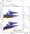 |
Fig. 5 Panel a: distribution of column densities as a function of linewidth. Panel b: number of components as a function of column density. Panel c: distribution of column densities divided by linewidth as a function of linewidth. Panel d: number of components as a function of column density divided by linewidth. Panel e: number of velocity components as a function of linewidth. The bin width is 0.5 km s−1. In all panels the two categories of line-of-sight clouds are coloured in yellow (Category I) and magenta (Category II), the clouds at about 50 km s−1 in cyan (Category III), and the components tracing the diffuse envelope of Sgr B2 in blue. In panels b, d, and e, the black histogram represents the full sample of detected components. |
Velocity ranges and associated locations of the clouds along the line of sight to Sgr B2.
4.3 Opacity maps
To investigate the spatial structure of the clouds we look for molecules that reveal absorption over an extended area of the field of view. We do not consider molecules with a resolved hyperfine structure that makes velocity assignments more complicated without fitting. Out of all molecules detected along the line of sight to Sgr B2, eight molecules fulfil these criteria: H13 CO+, 13CO, HNC and its isotopologue HN13C, HC15N, CS and its isotopologues C34S and 13CS, SiO, SO, and CH3OH. For some components the less abundant isotopologues are useful when the main isotopologue is optically thick. The spectroscopic parameters of the transitions of these selected molecules are listed in Table 4 and the example spectra towards the two positions K4 and K6shell (see Fig. 1) are shown in Fig. E.1.
We show in Fig. 6 the opacity maps of c-C3H2 at the 15 velocities listed in Table 3, and in Fig. 7 the maps of S/N. It is important to consider the S/N maps when interpreting the opacity maps because the noise level is not uniform due to the variations of the background continuum emission. The S/N maps are strongly correlated to the continuum map (see Fig. 1): the stronger the continuum the lower the opacity noise level.
At first sight, large-scale structures are detected in the opacity maps of nearly all velocity components (Fig. 6). The components at − 48.4 and − 3.2 km s−1 do not show such extended structures but this may simply result from a lack of sensitivity: their S/N maps indicate that the peak S/N is low (less than about 5 if we exclude K4) and only few positions have a S/N above 3.
The component at vLSR = 36.9 km s−1 looks more clumpy in Fig. 6, with three seemingly prominent, unresolved structures. However, all three opacity peaks have low S/N (~5) in Fig. 7. They may be noise artefacts and may not trace real compact structures.
The opacity and S/N maps of the other molecules are shown in Figs. F.1–F.22. The velocities of the channels differ slightly from the ones of c-C3H2 because of the discrete sampling of the frequency axis. The channels selected for these figures are the ones nearest to the velocities listed in Table 3. The pixels that have an opacity set to infinity (see Sect. 3.2) are masked (in cyan).
The type of structures seen in the opacity maps is similar for all molecules. In many cases, extended structures are present. Compact clumps that are present in some maps often have a low S/N and may simply be noise artefacts. The S/N of low-abundance molecules such as 13CS is too low to characterise the structural properties of the clouds. A better sensitivity would be needed for these tracers.
Because of the high number of opacity maps, we use in the following sections statistical tools to analyse and quantify the structure of the clouds traced in absorption towards Sgr B2(N).
Velocities and localisation of the diffuse and translucent molecular clouds detected with c-C3 H2 along the line of sight to Sgr B2, excluding Category III and the envelope of Sgr B2.
4.4 Cloud sub-structure
The two-point auto-correlation functions of c-C3H2 and H13CO+ are shown in Figs. 8 and 9, respectively. The two-point auto-correlation functions of the other molecules are displayed in Figs. G.1–G.10. Panels a–d of each of these figures show the two-point auto-correlation functions C(r) of the velocity components and panel e their S/N (C∕σC). The analysis of the two-point auto-correlation function of noise channels performed in Appendix C.1 indicates that only S/N values higher than 5 and 4 for pixel separations below and above 6′′, respectively, are significant. In addition, the true two-point auto-correlation function cannot be evaluated below a separation corresponding to the size of the beam (HPBW). As a result, the values of the two-point auto-correlation functions are significant only in the upper-right part of their S/N curves, above and right of the magenta demarcation in panels e.
The two-point auto-correlation functions show various shapes: flat, decreasing towards larger pixel separations, or stronger correlation at small and large separations with a dip in between. Flat curves indicate structures that are more extended than the region sampled with our data. Decreasing curves characterise clouds with structures that are somewhat more compact than the extent of the sampled region. The third type of shapes could result from the presence of several compact structures.
The maximum angular separation, Δrmax, at which C(r) drops below the significance threshold (magenta line in panels e) is given for each velocity component and each molecule in Table 5. When the S/N is too low, the opacity map is dominated by noise and no statement can be made about the sizes of the detected structures. The components with a peak S/N τ∕στ smaller than five are therefore marked with a star in Table 5. Most components with a Δrmax smaller than the beam (<2′′) are in this situation. When Δrmax is equal to the largest available pixel separation, only a lower limit for the size of the structures can be determined. We convert these angular sizes to physical sizes in Table 6, using the approximate distances listed in Table 3.
The two-point auto-correlation functions of the molecules c-C3H2, H13CO+, 13CO, HNC and its isotopologue HN13C, HC15N, CS and its isotopologues C34S and 13CS, and CH3OH are discussed in detail in Appendix H. The opacity maps suggest that most detected structures are extended on the scale of our field of view, ~15′′, or beyond. In a few cases, the two-point auto-correlation functions indicate the presence of smaller structures of sizes ~4–6′′. These structures are mostly seen for less abundant species for which most of the opacity map is dominated by noise. For example, the two GC clouds at 2.0 and 7.3 km s−1 are detected with high sensitivity for all investigated molecules and display structures that are more extended than 15′′ (~0.5 pc). The only exception is HN13C, but the shorter correlation length revealed by this tracer results from its lower abundance, hence a lower sensitivity, compared to the main isotopologue, HNC.
The other two molecules, SO and SiO, present a more complex picture (Figs. F.11 and F.13). Among the components with peak S/N higher than 5 in their opacity map (Figs. F.12 and F.14), the following ones reveal large-scale structures of the size of the field of view or larger: 2.4, 6.9, and −39.1 km s−1 in SO, and −3.2, 1.9, 7.0, 24.0, and 17.2 km s−1 in SiO. The structures traced with SO for three velocity components with a peak S/N of 6–8 in their opacity maps, at − 3.5, 32.1, and 36.6 km s−1, are more compact, with correlation lengths of ~8′′, 5′′, and unresolved, respectively. A similar type of compact structures with correlation lengths of ~8′′, unresolved, and 5′′ is revealed in SiO for the velocity components at − 105.5, − 27.1, and 37.7 km s−1 with peak S/N in their opacity maps of ~11, 6, and 6, respectively.
The two-point auto-correlation functions of SO and SiO at 7.3 km s−1 decrease first and increase again at pixel separations larger than about 10′′ (see Figs. G.5–G.6). In the opacity maps two smaller structures of sizes of 5′′ appear at offsets of about (1.′′5, 11.′′0) and (12.′′0, 10.′′0), with an angular separation of about 10.′′5 (see Figs. F.11 and F.13). Because they are at the edges of the available field of view, these structures may be more extended.
The two-point auto-correlation functions plotted depending on the physical distance are shown for the eight strongest molecules (c-C3H2, H13CO+, 13CO, CS, SO, SiO, HNC, and CH3OH) in Figs. G.11–G.18. For the seven molecules c-C3H2, 13CO, CS, SO, SiO, HNC, and CH3OH the auto-correlation functions decrease strongly for the cloud at a velocity of about 18 km s−1. The physical sizes derived for this cloud which is located in the Sagittarius arm are between 0.04 and 0.08 pc. The auto-correlation functions for this cloud have sometimes the same shape as the first part of the two-point auto-correlation functions seen for other clouds, for example for CS for the velocities of −2.7 and 18.4 km s−1 (see Fig. G.14). Hence, we may only see a smaller part of the cloud located closer to us, but with the same properties as of those clouds more distant from us. On the other hand, structures with sizes smaller than 0.04–0.08 pc (structure size in the Sagittarius arm) cannot be resolved in the more distant GC clouds. A better resolution is needed to investigate if there are smaller structures present.
Rotational transitions used in this work.
4.5 Turbulence in diffuse and translucent clouds
In order to investigate the turbulence properties of the clouds detected in absorption towards Sgr B2, we analyse the PDFs of their opacity maps. To reduce the influence of the noise on the Gaussian fitted to the PDFs (see Sect. C.2), we use a threshold of 3σnoise to analyse the profile of the PDFs. The PDFs P(η) of all 15 velocity components probed with c-C3H2 are shown in Fig. 10. The PDFs of the other molecules are plotted in Figs. I.1–I.11. The numberof Gaussians fitted to each PDF is indicated in Table I.1. The results of the Gaussian fits to the PDFs are displayed in Figs. I.12 and I.13, and the mean and median widths for each velocity component and for each molecule are listed in Tables I.2 and I.3, respectively.The velocity components that are optically thick and the ones dominated by the noise are marked in Table I.1. The number of fitted Gaussians seems to depend neither on the molecule nor on the velocity component. However, the molecules for which the PDFs are most often well fitted with a single Gaussian are HNC and c-C3H2, with only one and two velocity component(s) fitted with two Gaussians, respectively.
Tremblin et al. (2014) investigated the structure of the dense gas in several molecular clouds and explained the presence of two log-normal profiles or an enlarged shape of the PDF of a cloud as two different zones existing in the cloud. In the case they studied the turbulent molecular gas creates the low density part in the PDF and the second peak describes a compression zone created by the expansion of ionised gas into the molecular cloud. Another possibility is that the PDFs containing two log-normal profiles result from two different clouds overlapping along the line of sight at different distances from the observer but with the same velocity. We used opacity maps of only one channel and no integrated maps for the calculation of the PDFs to reduce the possibility of two clouds contributing to the same opacity map but such an overlap may still occur. Furthermore, our limited field of view that is set by the strength of the background continuum emission may have an effect on the shape of the PDFs. Because no velocity component shows a PDF with a two-Gaussian shape for all molecules, we believe that this particular shape does probably not characterise the true physical structure of the component. Therefore, to avoid being biased by the decomposition of the PDFs into two Gaussians, in the following we measure the width of each PDF by directly calculating its standard deviation, excluding the noise tail towards lower values of η. This cut may result in a slightly underestimated width of the PDF.
The distribution of PDF widths derived from the direct calculation is plotted in black in Fig. 11. The median and mean values are similar, with values of 0.52 and 0.53 for the total distribution, respectively. The distributions corresponding to Categories I and II defined in Sect. 4.2 are plotted in blue and magenta. Category I has a mean width of 0.48, somewhat smaller than Category II (0.56).
To investigate whether the shift between the two groups results from the different samples of molecules used for the different velocity components, we determine the distribution of PDF widths for the following five molecules only: c-C3H2, H13CO+, 13CO, CS, and HNC (see Fig. 12). These molecules are well detected over the field of view for almost all velocity components. The other molecules are not detected for some of the components. With this reduced sample of molecules, the two categories of velocity components still have mean PDF widths that differ, with values of 0.43 (Category I) and 0.50 (Category II). The widths are smaller than for the sample including all molecules. This is most likely due to the noise affecting the molecules that show weak absorption because the noise tends to broaden the PDF (Ossenkopf-Okada et al. 2016).
The widths of the PDFs of all molecules are plotted in Fig. 13 for all velocity components, sorted by their rough distance to the GC, and are listed in Table 7. To investigate whether there are systematic differences between the velocity components, we plot the mean and median values of each velocity component in panel b. We also show the mean and median values of each spiral arm and the GC in panel c. These values are also listed in Table 7. The median and mean values match each other within the uncertainties.
As seenin Fig. 11 there is a difference between Categories I and II. Category I contains the clouds in the 3 kpc and 4 kpc arms and the GC in the velocity range between − 106 and − 75 km s−1. They have narrower PDF widths than the clouds in Category II. The GC clouds belonging to Category I have widths between 0.47 and 0.52, the GC clouds of Category II have widths between 0.54 and 0.61. Especially the clouds in the 4 kpc arm have a narrower mean width, 0.41 ± 0.08, which is somewhat smaller than the overall mean value (0.52).
We also investigate whether the width of the PDFs depends on the molecule. Figure 14a shows the distribution of PDF widths as a function of molecule. The mean and median values are plotted in panel b and listed in Table 8. The molecules c-C3H2, H13CO+, and HNC have the narrowest widths. The less abundant isotopologues C34S, 13CS, HN13C, and HC15N and the less abundant molecules SO, SiO, and CH3OH have systematically broader PDF widths than the previous, more abundant molecules. This explains the difference seen between Figs. 11 and 12.
We use the widths of the PDFs to investigate the turbulent properties of the clouds probed in absorption by calculating the forcing parameter b (e.g. Federrath et al. 2010). For this calculation, we need the Mach number M which is defined as:
 (11)
(11)
with FWHM the linewidth of the molecule5 and cs the sound speed
 (12)
(12)
with Tkin the kinetic temperature, kB the Boltzmann constant, mH the mass of the hydrogen atom, and  the mean molecular weight (2.37, see, e.g. Kauffmann et al. 2008). Snow & McCall (2006) quote kinetic temperatures between 30 and 100 K for diffuse molecular clouds and between 15 and 50 K for translucent molecular clouds. Here, we assume temperatures of 20, 40, and 80 K. We determine the median FWHM for each velocity component and calculate the Mach number for the assumed temperatures (Table 9). We obtain Mach number values between 5.8 and 28.3 for Tkin = 20 K and between 2.9 and 14.2 for 80 K.
The forcing parameter b relates the velocity and density fields in a cloud (Padoan et al. 1997; Federrath et al. 2008):
 (13)
(13)
with σs the standard deviation of the volume density fluctuations and ση the dispersion of the two-dimensional column density or opacity fluctuations. The relation is derived from numerical simulations of magnetohydrodynamics (MHD) and hydrodynamics (Padoan et al. 1997; Passot & Vázquez-Semadeni 1998). In Federrath et al. (2010), the value of f is investigated in the extreme cases of purely solenoidal forcing (divergence free) and purely compressive forcing (curl-free): they obtain 2.9 for solenoidal forcing (f = σs∕ση = 1.32∕0.46) and 2.0 for compressive forcing (3.04∕1.51). They also define a parameter ζ that sets the power of compressive forcing with respect to the total power of the turbulence forcing. ζ takes values between 0 (purely compressive) and 1 (purely solenoidal). They show that b is a function of ζ (see their Fig. 8).
To calculate b from Eq. (13), we need to know f. Given that f does not vary much between the two extreme forcing cases investigated by Federrath et al. (2010), we assume that it is a simple linear function of ζ and parametrise it as f = 2.9 × ζ + (1 − ζ) × 2.0 (linear interpolation between the values of f obtained for the extreme cases ζ = 1 and ζ = 0). Equation (13) then gives us b as a function of ζ. The intersection of this function with the relation found by Federrath et al. (2010) gives the solution (b,ζ), when it exists. As an example, these functions are plotted for the different velocity components for a kinetic temperature of 40 K in Fig. 15. In many cases the two curves do not intersect for ζ between 0 and 1, but they come the closest to each other for ζ = 1. In these cases, we assume a value of 2.9 for f to derive b. In the other cases, the intersection gives us b and ζ.
We consider only the eight molecules with highest S/N to derive b for each velocity component: c-C3H2, H13CO+, 13CO, CS, SO, SiO, HNC, and CH3OH. The median values are listed in Table 9. We also compute for each molecule the median value of b over all velocity components (see Table 8).
The distribution of forcing parameter b is shown as a function of velocity component in Fig. 16 as an example for Tkin = 40 K. The median value of the forcing parameter b is 0.26, indicated bythe dashed line. b is higher for the velocity components that have low S/N for most molecules, which may be a bias due to the lack of sensitivity (vLSR = −81.5, − 48.4, and 24.7 km s −1). The values for the 4 kpc arm are significantly lower than the averaged value. The uncertainties for these values are relatively low. For a kinetic temperature of 40 K most values of b fall in the range 0.11–0.37. The forcing parameters b are smaller if weassume Tkin = 20 K (0.08–0.33) and larger for 80 K (0.16–0.47).
The distribution of forcing parameter b as a function of molecule is displayed in Fig. 17. Most molecules show similar values of b. Exceptions are C34S and HC15N, which lie above the other ones, probably due to their low S/N, and HNC, which lies below the average.
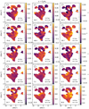 |
Fig. 6 Opacity maps of c-C3H2 21,2 –10,1 for all 15 investigated velocity components. In each panel, the velocity of the channel is given in km s−1 in the bottom left corner, the beam (HPBW) is shown as an ellipse in the upper left corner, and an approximate physical scale for the assumed distance of the cloud (see Table 3) is indicated in the bottom right corner. A star in the upper right corner marks the components with a maximum S/N τ/στ smaller than 5 (see Fig. 7). The equatorial offsets are relative to the phase centre. |
 |
Fig. 8 Panels a–d: two-point auto-correlation functions C(r) as a functionof pixel separation r for the velocity components traced with c-C3H2. The points give the mean values of the 1000 realisations and the colour-shaded regions represent the standard deviations (1σ). The centroidLSR velocities of the clouds are indicated in km s−1 at the top of each panel. Panel e: S/N of the two-point auto-correlation functions shown in panels a–d. The S/N levels of ±3, ± 4 and ± 5 are highlighted in shades of grey. The colours and symbols are the same as in panels a–d. The vertical dashed line shows the size of the beam (HPBW). The area below and left of the magenta line represents the area where the two-point auto-correlation functions are not significant. |
Angular sizes of cloud structures derived from two-point auto-correlation functions.
Physical sizes of cloud structures derived from two-point auto-correlation functions.
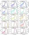 |
Fig. 10 Probability distribution functions P(η) of the velocity components probed with c-C3H2. The velocity of the component is indicated at the bottom of each panel in km s−1. The right y-axis indicates thenumber of pixels counted in each bin. The mean opacity |
 |
Fig. 11 Distribution of standard deviations (width) of the PDFs of all molecules for all 15 velocity components.
N
gives the total number of PDFs used for each histogram, |
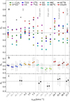 |
Fig. 13 Panel a: widths of the PDFs of all molecules for the 15 velocity components, roughly sorted by their distance to the Galactic centre. Panel b: mean (left) and median (right) values for each velocity component. Panel c: mean (left) and median(right) values for each sub-sample of clouds, from left to right: Galactic centre, 3 kpc arm, 4 kpc arm, Scutum arm, Sagittarius arm. The uncertainties represent the standard deviation for the mean and the corresponding percentiles for the median. The dashed line in each panel marks the mean value of all data points shown in panel a. Velocity components belonging to Category I and II are coloured in grey and black, respectively. |
Mean ( ) and median (
 ) widths directly computed from the PDFs for each velocity component.
4.6 Principal component analysis
Six of the 15 velocity components fulfil the selection criteria defined in Sect. 3.8 to perform a principal component analysis. The velocities of these components are: − 105.9, 2.0, and 7.3 km s−1 in the GC, 24.7 and 31.6 km s−1 in the Scutum arm, and 17.7 km s−1 in the Sagittarius arm. The molecules used for each component are listed in Table 10. The PCA is performed on the opacity maps after removing the average signal and scaling the standard deviation to 1. Hence, the PCA is sensitive only to the variance on scales smaller than the field of view.
To investigate the influence of the noise on the results of the PCA we performed a PCA on channels that contain only noise (see Appendix C.3). We used six molecules. The powers, that is the contributions of the principal components (PCs) to the total variance, are similar for the first three components and on the level of 20–30%. We conclude from this test that powers of the first PCs much higher than 20–30% are required to be considered as significant.
Becauseour field of view is limited by the extent of the background continuum emission, we performed several tests to examine therobustness of the PCA applied to our data (see Appendix D). For these tests we changed the grid size, the number of selected pixels, and the number of selected molecules. The PCA seems to be robust to these changes. However, when no clear structure is dominant for all molecules, decreasing the number of pixels results in more changes in the values of the PC coefficients.
The PCs calculated for vLSR = 24.7 km s−1 are shown in Fig. 18. The fourth component has a very small power of 1 × 10⁻²⁹. Hence, it can be neglected and is not displayed. The contribution factors of each PC to the selected molecules are shown in Fig. 19. The error bars represent the standard deviation calculated from the 1000 realisations of the opacity cubes. They are relatively small and barely visible. For this velocity component, 73% of the total variance in the data is described by the first principal component. This means a prominent structure is present for most molecules. The second and third PCs describe only small parts of the total variance 18 and 9%, respectively. The first two correlation wheels are plotted in Fig. 20a. H13CO+, HNC, and CS are anti-correlated to CH3OH for PC1. H13CO+ and CS are correlated for PC1 and PC3, but anti-correlated for PC2.
The correlation wheels for the other velocity components are displayed in Figs. 20b–f, the corresponding PCs and coefficients in Figs. J.1–J.10. The power of the fourth PC is always very low, on the order of 10−29. Hence, the fourth PC is not displayed in these figures. At vLSR = 31.6 km s−1 (Fig. 20e), HNC is anti-correlated to CH3OH, c-C3H2, and CS for PC1. The first component has only a contribution of 49% to the total variance. In PC2 (36%) c-C3H2 is strongly anti-correlated to CH3OH. CS is mostly described by PC3. At vLSR = −105.9 km s−1 (Fig. 20b), c-C3H2 and H13CO+ are anti-correlated with CH3OH and SiO with respect to the first PC. H13CO+ is mostly described by the third PC and CH3OH mostly by the second one. Here, the first PC has a high contribution of 65%.
The other velocity components have powers of their PCs in the order of 20–30%, similar to those obtained for pure noise channels. The correlation wheels of these components are therefore most likely not significant.
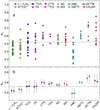 |
Fig. 14 Panel a: widths of the PDFs of 15 different velocity components along the line of sight sorted by molecule. Panel b: mean (left) and median (right) values for each molecule. The uncertainties represent the standard deviation for the mean and the corresponding percentiles for the median. The dashed line in both panels marks the mean and the median value for all components (see Fig. 11). |
PDF widths and parameters describing the turbulence for all investigated molecules.
PDF widths, linewidths, Mach numbers, and parameters describing the turbulence of the velocity components.
 |
Fig. 15 Forcing parameter b plotted against ζ for Tkin = 40 K for all15 velocity components. The different velocities are colour coded and given in km s −1. The magenta line represents the function derived from hydrodynamic simulations by Federrath et al. (2010). |
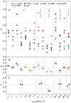 |
Fig. 16 Panel a: forcing parameter b of eight molecules, assuming Tkin = 40 K for the 15 velocity components roughly sorted by their distance to the Galactic centre. Panel b: mean (left) and median (right) values for each velocity component. Panel c: mean (left) and median (right) values for each sub-sample of clouds, from left to right: Galactic centre, 3 kpc arm, 4 kpc arm, Scutum arm, Sagittarius arm. The uncertainties represent the standard deviation for the mean and the corresponding percentiles for the median. The dashed line in each panel marks the median value of all data points shown in panel a. The velocities of the components belonging to Categories I and II are colouredin grey and black, respectively. |
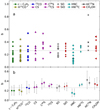 |
Fig. 17 Panel a: forcing parameter b of up to 15 velocity components sorted by molecule and assuming Tkin = 40 K. Panel b: mean (left) and median (right) values for each molecule. The uncertainties represent the standard deviation for the mean and the corresponding percentiles for the median. The dashed line in both panels marks the median value of the sub-sample of molecules used in Fig. 16. |
Molecules used for the PCA for six velocity components.
 |
Fig. 18 Principal components determined at vLSR = 24.7 km s−1. The colours give the intensity. The absolute value of each PC is normalised to 1 as explained in Sect. 3.8. The percentages in parentheses give the contributions of the PCs to the total variance. |
4.7 Nature of the detected line-of-sight clouds
In order to understand the nature of the line-of-sight clouds detected towards Sgr B2(N), that is whether they are diffuse or translucent, we want to estimate their H2 column densities and visual extinctions, Av. HCO+ has been shown to be a good tracer of H2 in diffuse clouds, with N(HCO+)/N(H2) = 3 × 10⁻⁹ (Liszt et al. 2010). Here we use the EMoCA spectrum towards K4 to derive the HCO+ column densities of the clouds detected in absorption. For the velocity components for which HCO+ 1–0 is optically thick, we model H13CO+ 1–0 and assume the same 12 C/13C ratios as Belloche et al. (2013) to derive the HCO+ column densities (see their Table 2). We use Weeds (Maret et al. 2011) to model the velocity components detected towards K4 in absorption. The resulting parameters are listed in Table 11 and the synthetic spectra are shown in Fig. 21. We obtain H2 column densities ranging from 3.3 × 10²⁰ to 9.0× 1022 cm−2, which corresponds to Av between 0.4 and 96 mag (Cols. 4 and 5 in Table 11).
With the HCO+ abundance relative to H2 assumed above, all but three components (at vLSR = −83.9, − 114.1, and − 134.6 km s−1) would have visual extinctions higher than 5 mag, which would imply that they are dense molecular clouds. If this were indeed the case, then we would expect to see these clouds in emission towards positions without strong continuum background. To test this, we cannot use the EMoCA survey because of the spatial filtering of the interferometer. Instead, we check the imaging survey of Sgr B2 performed by Jones et al. (2008) with Mopra at 3 mm. We select the following transitions: HCO+ 1–0, HNC 1–0, CS 2–1, and 13CO 1–0. The HCO+, HNC, and CS lines are partly seen in absorption in the Mopra data. We mask the pixels where absorption is detected in the velocity range from − 100 to 0 km s−1. For each of these three species, we compute the average Mopra spectrum within a square box of size 156′′ centred on the J2000 equatorial position 17h47m19.8s, −28°22′17′′, excluding the masked pixels (see Fig. 22). 13CO 1–0 does not show any absorption in the Mopra spectra and we take the average spectrum over a square box of size 84′′ centred on the same position (see Fig. K.1). The resulting Mopra spectra are compared to the EMoCA spectra in Figs. 23, 24, K.2, and K.3.
The 13CO Mopra average spectrum shows two strong velocity components in emission that match well the position of components seen in absorption in the EMoCA spectrum (at − 42 and 5 km s−1, see Fig. 24). Two weaker emission peaks at − 83 and − 107 km s−1 also match absorption components seen with ALMA. None of the components at velocities below − 30 km s−1 are detected in emission in the HCO+, HNC, and CS Mopra spectra, but these species show emission at velocities above approximately − 30 km s−1, which may be at least in part associated with the absorption components seen in the ALMA spectra.
We perform non-LTE radiative transfer calculations with RADEX (van der Tak et al. 2007) to estimate the densities and kinetic temperatures that are consistent with the emission seen with Mopra, or its upper limits. We take the spectroscopic parameters and collisional rates with H2 from the Leiden Atomic and Molecular Database (LAMDA, Schöier et al. 2005) for HCO+ (Botschwina et al. 1993; Flower 1999; Schöier et al. 2005), CS (CDMS, and Lique et al. 2006), HNC (CDMS, and Dumouchel et al. 2010), and 13CO (CDMS, JPL, and Goorvitch 1994; Cazzoli et al. 2004; Yang et al. 2010). We perform the calculations for a wide range of parameters: 10–130 K for the kinetic temperature and 10–107 cm−3 for the H2 density. These ranges cover the values expected for diffuse, translucent, and dense molecular clouds. We explore the following ranges of column densities: 1012.5–14.5 cm−2 for HCO+, 1012.0–14.5 cm−2 for HNC, 1012.5–14.5 cm−2 for CS, and 1015.0–16.5 cm−2 for 13CO. They correspond to the ranges derived from the absorption features detected with ALMA towards six strong continuum positions covered by EMoCA. The brightness temperatures computed with RADEX for the selected transitions are displayed in Figs. 25 and L.1–L.3, respectively. The solid lines plotted in these figures indicate the level of emission detected with Mopra for the component around 14 km s−1. For 13CO, the dashed lines correspond to the emission component detected around 83 km s−1, while for the other species, they correspond to the emission upper limits (three times the RMS noise level) derived from the Mopra spectra between − 110 and − 10 km s−1. We converted the Mopra antenna temperatures into brightness temperatures by multiplying them with a factor 1.7, which roughly corresponds to the extended beam efficiency of ~ 0.6 measured by Ladd et al. (2005) for sources larger than ~ 80′′, consistent with the extended emission seen in the Mopra channel maps shown in Figs. 22 and K.1.
Given the limits assumed for the kinetic temperature, our RADEX analysis provides constraints on the molecular hydrogen densities (see Table 12). For the component around 6 km s−1, the ranges of densities derived from HCO+ and 13CO are similar, on the order of 30–5000 cm−3, while the ranges derived for HNC and CS are shifted by nearly one order of magnitude towards higher densities. For the component at − 83 km s−1 detected in emission in 13CO 1–0, the upper end ofthe density range is 500 cm−2. The upper limits derived for HCO+, HNC, and CS over the range − 110 to − 10 km s−1 imply densities below 5 × 103 cm−3, 5 × 105 cm−3, and 3 × 104 cm−3, respectively.Some of the RADEX plots also show higher density solutions for CS and 13CO but these solutions would not be consistent with the constraints set by HCO+. Our RADEX analysis does not bring any constraint on the kinetic temperature.
Our calculations with RADEX do not take the collisional excitation by electrons into account. Electrons can have a significant impact on the excitation of molecules at low densities when the electron fraction is high and the CO fraction is small (Liszt & Pety 2016). Taking the collisional excitation by electrons into account in our radiative transfer calculations would lower the densities or upper limits derived in this section.
 |
Fig. 19 Principal component coefficients determined at vLSR = 24.7 km s−1. The contribution factors of each molecule are normalised such that the sum of the squares is equal to 1. The percentages in parentheses give the contributions of the PCs to the total variance. |
 |
Fig. 20 Correlation wheels for PCs at vLSR = 24.7 km s−1 (panels a), − 105.9 km s−1 (panels b), 2.0 km s−1 (panels c), 7.3 km s−1 (panels d), 31.6 km s−1 (panels e), and 17.7 km s−1 (panels f). The percentages in parentheses give the contributions of the PCs to the total variance. The ellipses around the arrow heads show the uncertainties estimated from 1000 realisations of the opacity cubes. |
H2 column densities and visual extinctions derived from the HCO+ column densities determined in the ALMA spectrum in the direction of K4.
 |
Fig. 21 ALMA spectra of HCO+ 1–0 and H13CO+ 1–0 (shifted by +4 K) in the direction of K4 in black. The synthetic spectra of HCO+ and H13CO+ computed with Weeds are overplotted in blue and magenta, respectively. |
5 Discussion
5.1 Types of line-of-sight clouds
Assuming that HCO+ has the same abundance relative to H2 as the one established for diffuse clouds (3 × 10⁻⁹) leads to the conclusion that most clouds seen in absorption in the EMoCA survey would be dense clouds, with visual extinctions higher than 5 mag (Table 11). However, the maps obtained towards Sgr B2 with Mopra by Jones et al. (2008) reveal only few velocity components in emission in the tracers HCO+ 1–0, HNC 1–0, CS 2–1, and 13CO 2–1. Our radiative-transfer analysis indicates that the emission component at ~ 6 km s−1 detected in 13CO 2–1 and HCO+ 1–0 must have an H2 density lower than a few times 103 cm−3. In addition, our analysis of the ALMA HCO+ 1–0 absorption spectrum towards K4 indicates that, except for the component at − 83.9 km s−1, the velocity components between − 110 and − 10 km s−1, which are not detected in emission in the HCO+ 1–0 Mopra data, have HCO+ column densities higher than 1013 cm−2 (Table 11). The radiative-transfer calculations then imply that these components have H2 volume densities below 103 cm−3 (Fig. 25). Finally, the component at approximately − 83 km s−1 detected in 13CO 2–1 emission with Mopra also has a low density, less than 500 cm−3, according to our radiative-transfer analysis (Sect. 4.7). Taking the collisional excitation of molecules by electrons into account would imply even lower densities. All components between − 110 and − 10 km s−1 and the one at 6 km s−1 thus have densities that are too low for them to be dense clouds, which are characterised by densities higher than 104 cm−3 (Snow & McCall 2006). We note that Greaves (1995) derived densities in the order of 104 cm−3 for the clouds at velocities − 102, − 41, − 27, and 3 km s−1 on the basis of HCN 3–2 probed in absorption with the JCMT, while their CS 2–1 and 3–2 observations of the same clouds in absorption indicate densities lower than 600 cm−3, in rough agreement with our conclusion above. These authors concluded that a range of densities from ~ 200 cm−3 up to 104 cm−3 must be present in these clouds.
The components discussed in the previous paragraph are not dense clouds, and they cannot represent diffuse clouds either, otherwise we would obtain visual extinctions lower than 1 mag when computing their H2 column densities with the standard diffuse-cloudabundance of HCO+. We conclude that the clouds with velocities between − 110 and − 10 km s−1 and at 6 km s−1 are translucent clouds, and that the HCO+ abundance relative to H2 must be higher than 3 × 10⁻⁹ in these clouds, by at least a factor of two, and maybe even a factor of six in order to reconcile the visual extinction of the component at − 104 km s−1 with its translucent nature (Av should be between 1 and 5 mag). All these conclusions hold only if our assumption that the HCO+ column densities derived from our ALMA absorption spectra are representative of the HCO+ column densities at the scales probed with Mopra.
Our conclusion that HCO+ likely has a higher abundance in translucent clouds compared to diffuse clouds is consistent with the results of the GEMS survey performed by Fuente et al. (2019) with the IRAM 30 m telescope towards the dark cloud TMC1. They report that HCO+ reaches its maximum abundance relative to H2 at a visual extinction of 5 mag, with a value of ~2 × 10⁻⁸. A visual extinction of 5 mag corresponds to a H2 column density of 4.7 × 1021 cm−2, which implies a HCO+ column density of 9.4 × 1013 cm−2 assuming the HCO+ abundance above. The transition between diffuse and translucent clouds at a visual extinction of 1 mag corresponds to an H2 column density of 9.4 × 1020 cm−2, that is a HCO+ column density of 2.8 × 1012 cm−2 assuming the ≈7 times lower standard HCO+ abundance for diffuse clouds (3 × 10⁻⁹). Most components in Table 11 have HCO+ column densities between these two values, implying that they are translucent clouds. The exceptions are the component at − 134.6 km s−1, which corresponds to a diffuse cloud, and the components at − 41.2 km s−1, 18.6 km s−1, and 3.8 km s−1, which must be dense clouds. To have a better estimate of the H2 column density and visual extinction of each component, we recompute these quantities assuming a HCO+ abundance of 3 × 10⁻⁹ for N(HCO+) < 2.8 × 1012 cm−2, 2 × 10⁻⁸ for N(HCO+) > 9.4 × 1013 cm−2, and an interpolated value (in log–log space) in between (see Table 11).
In Thiel et al. (2017), some of us reported on the basis of the EMoCA survey the detection of complex organic molecules in four velocity components (one in the Scutum arm and three in the GC region) that we ascribed to what we termed diffuse clouds. Liszt et al. (2018) questioned the diffuse nature of these clouds on the basis of their high HCO+ column densities. The detailed analysis performed here confirms that these components with COM detections are not diffuse. Instead, we find that the component in the Scutum arm (at 27 km s−1) and two of the GC components (at 9.8 and − 1.7 km s−1) are translucent clouds. The third GC component has a visual extinction of 8.5 mag suggesting it is somewhat dense, but still close to the border between translucent and dense clouds. Therefore, we conclude that complex organic molecules are present in some translucent clouds along the line of sight to Sgr B2.
 |
Fig. 22 Mopra channel maps in the direction of Sgr B2 at about 14 km s−1 for HCO+ 1–0 (panel a), HNC 1–0 (panel b), and CS 2–1 (panel c) as observed by Jones et al. (2008). In each panel, the white box shows the region selected to calculate the averaged spectrum and the green contour encloses the pixels that were masked to avoid absorption. The white circle in the lower right corner of each panel represents the beam and the cross indicates the position of K4. The pixel size is 12′′. |
 |
Fig. 23 Mopra average spectrum of HCO+
1–0 towards Sgr B2(N), extracted from the imaging survey of Jones et al. (2008) after excluding pixels with absorption (see Fig. 22). The black and blue spectra were obtained with the broad-band and narrow-band backends, respectively. They are displayed in
|
 |
Fig. 24 Same as Fig. 23, but for 13CO 1–0. The ALMA spectrum is resampled to the spectral resolution of the Mopra spectrum. The dashed lines mark emission peaks that match well absorption features of the EMoCA spectrum outside the velocity range of the Sgr B2 envelope. |
 |
Fig. 25 HCO+ 1–0 brightness temperature computed with RADEX as a function of kinetic temperature (x-axis) and H2 density (y-axis), assuming different column densities. In each panel, the solid line corresponds to the level of emission measured in the Mopra spectrum around 14 km s−1 and the dashed line to the upper limit (3σ) over the velocity range from − 110 km s−1 to − 10 km s−1. The solid line is displayed only for the column densities that fall in the range determined from the ALMA absorption map at this velocity and the white star marks the median column density obtained from the ALMA absorption map at this velocity. |
H2 densities derived from the Mopra data.
5.2 Suitable tracers of H2 in translucent clouds
The fact that HCO+ has a higherabundance in translucent clouds compared to diffuse clouds has an impact on the analysis of the CH abundance performed by Qin et al. (2010) for the clouds probed in absorption with Herschel towards Sgr B2(M). They took HCO+ as a proxy for H2 and assumed a uniform abundance of 5 × 10⁻⁹. With this assumption, the distribution of CH and H2 column densities does not follow the correlation found by previous studies for diffuse clouds. However, if we take into account the variation of the HCO+ abundance as described above, we find a correlation between CH and H2 much closer to the diffuse-cloud correlation. The kink at an H2 column density of 1021 cm−2 reported by Qin et al. (2010) vanishes (see Fig. M.1). The correlation of CH to H2 determined by Sheffer et al. (2008) for diffuse molecular clouds is now valid for H2 column densities up to 1021.7 cm−2, which meansthat CH is a good tracer of H2 up to Av ~ 5.3 mag. At  cm−2, we see a deviation from the correlation. Hence, the CH abundance relative to H2 must decrease somewhere between 1021.7 and 1023 cm−2. This is consistent with the drop of CH abundance above a H2 column density of 5 × 1021 cm−2 reported for TMC-1 by Suutarinen et al. (2011).
CCH is strongly correlated with CH in diffuse molecular clouds (Gerin et al. 2010b). There is also a tight correlation between CCH and c-C3H2 in translucent clouds (for N(c-C3H2) < 1012.5 cm−2; Lucas & Liszt 2000; Gerin et al. 2011). Here, we want to investigate whether both CCH and c-C3H2 are good tracers of H2 in translucent clouds. Figure 26 shows the distribution of CCH column densities as a function of H2 column densities for the velocity components detected towards six positions with strong continuum background in our survey, along with measurements reported in the literature for other diffuse and translucent clouds. In this plot, the H2 column densities are derived from the HCO+ column densities assuming the same non-uniform HCO+ abundance profile as in Sect. 5.1. Overall, we see that CCH is well correlated with H2 for both diffuse and translucent clouds. The slope of unity indicates that it can be used as a good tracer of H2 up to Av = 5 mag at least. The correlation is a bit tighter for the GC translucent clouds than for the ones located in the disk of our Galaxy, with a slope slightly higher and lower than unity for the former and latter, respectively.
Figure M.2 shows the same plot for c-C3H2. If we take all data together, there is an overall correlation between c-C3H2 and H2 with a slope close to unity, but a fit limited to the ALMA data only yields a much flatter correlation, with a large dispersion. c-C3H2 does not seem to correlate as tightly with H2 as CCH in the translucent regime. This larger dispersion is dominated by the clouds located in the Galactic disk for which there is no correlation between c-C3H2 and H2. The correlation is tighter for the GC clouds with, however, a slope higher than unity. In both cases, c-C3H2 thus does not appear as a good tracer of H2.
The column densities of CCH and c-C3H2 are plotted against each other in Fig. M.3. Here also, while there is an overall correlation with a slope close to unity for the full sample of diffuse and translucent clouds, the fit limited to the ALMA data departs significantlyfrom a slope of unity. Therefore, our data do not reveal a tight correlation between CCH and c-C3H2 beyond therange of C3 H2 column densities explored by Lucas & Liszt (2000) and Gerin et al. (2011). This conclusion holds also for the GC or galactic disk clouds taken separately (see magenta and green fits in Fig. M.3).
 |
Fig. 26 Distribution of CCH column densities versus H2 column densities, calculated from HCO+ as described in Sect. 5.1. The filled symbols represent the values obtained for the velocity components detected toward six positions with strong continuum background in the ALMA data. Their equatorial offsets are indicated tothe right. The fainter filling colours are used for the GC components. The red crosses are measurements from Godard et al. (2010) and Gerin et al. (2011) and the black ones from Lucas & Liszt (1996, 2000). The dashed lines are linear fits to the following samples: all data (blue), ALMA data only (black), ALMA GC components only (magenta), and ALMA disk components only (green). The dotted-dashed lines are fits with a slope of unity. The fits results are given in the upper left corner with their uncertainties. The Pearson correlation coefficients r are given onthe right side. The vertical lines highlight the limits between diffuse, translucent, and dense clouds. |
5.3 Velocity components and velocity dispersions
Previous absorption studies revealed velocity components similar to those we found in our data. Corby et al. (2018) used GBT data to investigate ortho c-C3H2 (11,0 − 10,1) at 18.343 GHz. They detected many narrow features with FWHM ≲ 3 km s−1 which are superimposed on components with widths between 3 and 16 km s−1. They suggested at least ten distinguishable line-of-sight absorption components. Garwood & Dickey (1989) used VLA data with a spectral resolution of 2.6 km s−1 to investigate HI in absorption along the line of sight to Sgr B2(M). Because the velocities in the direction of Sgr B2(N) are similar to those in the direction of Sgr B2(M) (Greaves & Williams 1994), we chose these velocities for comparison. The components detected by Corby et al. (2018) and Garwood & Dickey (1989) are compared to ours in Table 13.
All velocity components found by Garwood & Dickey (1989) are detected in this work and in the data examined by Corby et al. (2018). Corby et al. (2018) modelled the spectrum using several broad Gaussian components overlaid with narrower Gaussian features resulting in a higher number of velocity components than we investigate here. Corby et al. (2018) detected two velocity components, at − 120 and − 58 km s−1, for which we see no clear counterparts in our c-C3H2 spectra. The component at − 58 km s−1 is detected towards a few positions but because of the poor statistics, we decided not to investigate this component. The component at − 120 km s−1 is detected in other molecules such as HCN or HCO+ (see Table 11), so our non-detection of this component in c-C3H2 is due to a lack of sensitivity. Belloche et al. (2013) investigated the velocity components of c-C3H2 along the line of sight to Sgr B2 using the IRAM 30 m telescope. They were also able to find a few additional velocity components compared to the components reported here. In our analysis, we only consider the velocity components associated with the strongest peaks (minima) of the absorption of c-C3H2. The programme we wrote to fit synthetic spectra to the 322 investigated positions may underestimate the number of velocity components in some cases because we do not allow peak velocities to be closer to each other than two channels (see Sect. 3.5). This approach still yields good fits to the observed spectra (see Fig. 3). In addition, the number of identified velocity components depends on the investigated position. Because our main goal is to investigate the spatial structure of the diffuse and translucent clouds seen in absorption, we selected the velocity components for which a cloud is detected towards a sufficient number of positions. The detection of components depends also on the strength of the continuum. The IRAM 30 m and GBT single-dish data have angular resolutions of ~30′′ and ~40′′, respectively, which means that they are much more sensitive to the extended continuum emission and they include the two main hot cores Sgr B2(N1) and Sgr B2(N2). The stronger continuum of Sgr B2(N1) (see Fig. 1) reveals more velocity components in our data but they are too weak to be detected at lower continuum values. These hot-core positions are however affected by contamination from numerous emission lines in the 3 mm atmospheric window, which is the reason why we excluded them from our analysis.
The smallest linewidth we derive for a velocity component traced by c-C3H2 is 1.74 km s−1, which is equal to the channel width. The largest width is about 20 km s−1 (see Fig. 4). Corby et al. (2018) found a range of FWHM between ~1 and 10 km s−1, plus two broad components with FWHM ~ 16 km s−1 that probably result from the overlap of several narrower components. The majority (84%) of the widths derived here is smaller than 11 km s−1 (see Fig. 4), thus falling in the same interval. Belloche et al. (2013) found typical widths of the line-of-sight clouds of 3–5 km s−1, and Menten et al. (2011) values between 3 and 8 km s−1. Gerin et al. (2010a) studied the diffuse and translucent clouds along the line of sight to G10.6-0.4 and found values between 3 and 6 km s−1 for the FWHM. The median value of Category I, 5.4 km s−1 (Table 2), lies at the upper edge of these ranges for the FWHM. If we look at the width distribution of Category I (see Fig. 4a), the majority (75%) of the velocity components have FWHM smaller than about 7.5 km s−1. For larger widths the number of velocity components is decreasing. This tail could be caused by overlapping velocity components that could not be fitted separately.
The largest FWHM derived from our fits is 20 km s−1. Wiesemeyer et al. (2016) investigated OH and OH+ along the lines of sight to other continuum sources than Sgr B2 and found velocity components with widths up to 18 km s−1 for OH and up to 23 km s−1 for OH+ covering the same velocity interval. The distribution of their FWHM shows that most velocity components have smaller widths and only a few have FWHM larger than 10 km s−1. Their explanation for the wide variance of determined FWHM is that the absorption of single clouds may cause the narrow features, whereas the larger widths of the velocity components may be caused by the blending of the contribution from several clouds along the lines of sight. Furthermore, the large beams of single dish telescopes may cause spatial blending effectively resulting in larger line widths. As explained in Sect. 4.2 the programme we used for the modelling of c-C3H2 is not able to distinguish between a single broad Gaussian and multiple overlapping components producing the same shape. In those cases a single Gaussian is assumed, which likely explains the tail we obtain to higher FWHM and a smaller number of velocity components. Corby et al. (2018) investigated the OH absorption spectrum towards Sgr B2 at 1612 MHz and 1667 MHz. The former line shows linewidths larger than 10 km s−1 (up to 50 km s−1) for most velocity components while for the latter half of the components have widths smaller than 10 km s−1, but still larger than c-C3H2. Here again, the velocity overlap between clouds probably leads to an overestimate of the OH linewidths in some cases. Summarising, it seems that c-C3H2 traces less diffuse regions with smaller velocity dispersions than OH.
Velocities of diffuse and translucent clouds along the line of sight to Sgr B2.
5.4 Cloud sizes
The two-point auto-correlation functions of the opacity maps suggest that most detected structures are extended on the scale of our field of view, ~15′′, or beyond (Sect. 4.4). This means that our assumption of a beam filling factor of 1 to fit the spectra is reasonable. In a few cases, the two-point auto-correlation functions indicate the presence of smaller structures of sizes ~4′′–6′′. These structures are mostly seen for less abundant species for which most of the opacity map is dominated by noise. For example, HN13C shows small structures for the GC cloud at 2.0 km s−1, but the main isotopologue HNC shows an extended structure at this velocity. Therefore, we believe that most of the compact structures suggested by the two-point auto-correlation functions simply result from a lack of sensitivity. More sensitive observations would likely detect the same underlying extended structures traced by the more abundant molecules.
The auto-correlation functions of SO and SiO suggest a clumpy structure for some of the velocity components, which cannot be explained by a lack of sensitivity for these molecules. The signal-to-noise ratio is relatively good for SiO at velocities between − 5 and 25 km s−1 and for SO between 0 and 10 km s−1. Hence, the clumps seen at these velocities are significant. Especially at the velocity of 7.0 km s−1, which corresponds to a translucent cloud, these two molecules have a high S/N and reveal a smaller structure in the opacity maps of size of 5′′ at an offset of (1.′′5, 11.′′0) (see Figs. F.11 and F.13). The physical size of these clumps is in the order of 0.2 pc. SiO also shows a more complex structure at 17.2 km s−1 in the Sagittarius arm. A denser clump peaked at (6.′′5, 5.′′ 0) with a size of about 8′′ (0.04 pc) isoverlying a more extended structure. Except the clump at (6.′′5, 5.′′ 0), the clumps detected in SiO and SO are located close to the boundaries of the available field of view. Hence, we may not see the complete structure of the clump and the determined size is only a lower limit.
The structures of sizes 0.04–0.08 pc seen in some molecules at the velocity of the Sagittarius arm can not be spatially resolved for the GC clouds. Observations with higher spatial resolution are needed to investigate if such smaller physical structures are present in the GC clouds.
The absorption components detected towards Sgr B2(N) and Sgr B2(M), which are separated by ~50′′, have similar velocities (Greaves & Williams 1994). This suggests that the structures of the foreground clouds detected in absorption are more extended than 50′′, which can be seen in 13CO large-scale emission maps.
5.5 Turbulence
The PDFs analysed in Sect. 4.5 can be described by one or two log-normal distributions. A log-normal profile characterises the low density part of the PDFs of star-forming regions (e.g. Schneider et al. 2013). Isothermal hydrodynamic simulations including turbulence and gravity have shown that a power tail at higher densities arises due to gravitational collapse/contraction (e.g. Klessen 2000). When gravity is not included in the simulations, only the log-normal part remains in the PDF (Padoan et al. 1997; Kritsuk et al. 2007; Federrath et al. 2008).
The log-normal part of the PDF is not influenced by resolution effects and should be unchanged by using larger beam sizes (Schneider et al. 2015b; Federrath & Klessen 2013). But in cases where the pixel distribution used for determining the PDF is not covering the complete structure, a fall off at lower densities can appear (Schneider et al. 2015a). If the structure is not completely covered by the field of view of the observations, the width can be underestimated and the peak position overestimated (Ossenkopf-Okada et al. 2016). Due to the limitations set by the background continuum emission on our actual field of view, we most likely do not trace the complete structure of the line-of-sight clouds. Hence, the width of their PDFs is likely underestimated.
The volume-weighted density PDF in numerical simulations has a wider dispersion than the column density PDF, but shows similar properties (Federrath et al. 2010). Both PDFs are nearly perfect log-normal distributions in simulations without gravity, only small effects seen as non-Gaussian features are present (see Federrath et al. 2010). The effects can be high- and low-density wings (e.g. Passot & Vázquez-Semadeni 1998; Kritsuk et al. 2007; Federrath et al. 2010). We sometimes see such weak wings in our data (see, e.g. Fig. I.4 at vLSR = −81.3 km s−1), but they do not influence the parameters of the fitted log-normal profiles and also have only weak influence on the calculated dispersion of the profiles.
Federrath et al. (2008) investigated the gas density in turbulent supersonic flows by performing numerical simulations. They examined the differences in the column density fields for solenoidal forcing (divergence free) and compressive forcing (curl-free). They fixed the Mach number to 5.5. A result of the analysis is that the compressive forcing leads to a much higher density contrast than the solenoidal forcing despite the same Mach number. Solenoidal forcing is mostly present in more quiescent regions with low star formation rates, which is also seen in observations (Federrath et al. 2010). For both the volume-weighted density PDF and the column density PDF, the width of the lognormal part of the PDF is three times larger for compressive forcing than for solenoidal forcing. The compressive forcing of the turbulence as well as a higher Mach number broaden the PDFs (Federrath & Klessen 2013).
The width of the column density PDF for purely solenoidal forcing is determined in simulations to be ση = 0.46 ± 0.06 (Federrath et al. 2010), which is similar to the average value of our sample of 15 diffuse and translucent clouds (0.52). The larger widths we obtained for low-abundance species (C34S, 13CS, HN13C, and HC15N) is likely dueto the lack of sensitivity and the stronger influence of the noise (Ossenkopf-Okada et al. 2016). The width of column density PDFs for purely compressive forcing would be ση = 1.51 ± 0.28 (Federrath et al. 2010). We therefore conclude that on average, the turbulence of the diffuse and translucent clouds traced in absorption in our data is mainly solenoidally driven, provided the bias resulting from our limited field of view is not too strong.
We derived in Sect. 4.5 the turbulence parameters ζ and b from the width of the PDFs of all 15 velocity components using c-C3H2, H13CO+, 13CO, CS, SO, SiO, HNC, and CH3OH. Because these parameters depend on the Mach number, the kinetic temperature is needed and we assumed a range of 20 K to 80 K to cover roughly the range of temperature possible in diffuse and translucent molecular clouds. With this range of temperature, the range of Mach number of the velocity components we detected is 2.9–28.3.
The question is which kinetic temperature is more likely: 20, 40, or 80 K. The investigation of H2 using far-UV observations shows a temperature for diffuse clouds of 50–150 K depending on the investigated line of sight (Snow & McCall 2006, and references therein). The mean value is about 80 K. The temperatures in the direction of ζ Persei derived using C2 is 80 ± 15 K, and using H2 58 ± 8 K (Snow & McCall 2006, and references therein). The temperature in the direction of o Persei is a bit lower, 60 ± 20 K using C2 and 48 ± 5 K using H2 (Snow & McCall 2006, and references therein). The temperature seems to show a high variance. However, as we concluded in Sect. 5.1, most clouds along the line of sight to Sgr B2 are translucent. Hence, the kinetic temperature is likely lower than the temperature of diffuse clouds mentioned above. Fuente et al. (2019) derived a temperature of 13–14 K for visual extinctions below 7.5 mag in TMC-1. Therefore, we believe that the temperature of the translucent clouds investigated here is between ~15 and ~50 K. Our radiative-transfer calculations (Sect. 4.7) do unfortunately not deliver any constraint on the kinetic temperature. In summary, for most of the line-of-sight clouds of our sample we favour temperatures of 20 or 40 K, but we cannot exclude a higher temperature for the diffuse cloud in our sample.
For any of the three temperatures assumed above, the forcing parameter b is always smaller than 0.5 for all components. This confirms the conclusion drawn above that the turbulence is dominated by solenoidal forcing in the translucent clouds investigated here.
Many values of the forcing parameter b are either smaller than the value expected for purely solenoidal forcing or a bit larger, but still relatively close to 1/3. Values of b < 1/3 are in principle not possible in the framework of the turbulence investigated in the simulations (Federrath et al. 2010). The underestimation of b could result from an underestimation of the width of the PDF because of the limited field of view, as mentioned above. A second reason for a low value of b could be an overestimation of the linewidth, for instance due to the overlap of several components along the line of sight. For example, b is relatively small for the following velocity components: − 74.6, 2.0, − 27.6, − 18.9, and 31.6 km s−1. The median FWHM for those components is on average larger in comparison with the other velocity components (7.1–10.2 km s−1).
In summary, our investigation of the PDFs of the clouds along the line of sight to Sgr B2 shows that the driving of the turbulence is purely solenoidal, or at least dominated by solenoidal forcing. Solenoidal forcing causes smaller density contrasts (Federrath et al. 2008), which results in more homogeneous cloud structures. This is consistent with the lack of sub-structures that we noticed on the basis of our analysis of the two-point autocorrelation functions of the opacity maps.
Studies of three translucent high-latitude clouds, MBM 16, MBM 40, and MBM 3, show that the motions inside the clouds are highly correlated in clumps which have sizes of about 0.5 pc (Magnani et al. 1993; Shore et al. 2003, 2006, 2007). This scale corresponds to the extent of the field of view we have in our ALMA data for the most distant clouds. The clumps in the translucent high-latitude clouds are located in a more diffuse structure. They are not self-gravitating and do not show star-formingactivity. Some significant changes in emission at the scale of 0.03 pc are visible resulting in strong density gradients of a factor up to 10. In our data towards Sgr B2, we see, for a few molecules, structures at scales of about 0.04–0.08 pc only for the line-of-sight clouds located closer to us where such scales are resolved. The dynamics inthe translucent high-latitude clouds was shown to result from the combination of shear flows and thermal instabilities, with the large-scale shear flow powering the turbulence and the density field maybe caused by thermal instability. Because we see also homogeneous structures on scales up to 0.55 pc roughly the size of the clumps detected in the high-latitude clouds, maybe the same processes are at work in the line-of-sight clouds investigated here.
5.6 Meaning of the cloud categories
We have divided the clouds detected in absorption along the line of sight to Sgr B2 into two categories on the basis of their c-C3H2 column densities. Category I, with lower c-C3H2 column densities (1012.8 cm−2 on average), contains the GC clouds with LSR velocities below − 50 km s−1 and the clouds belonging to the 3 and 4 kpc arms. The GC clouds with velocities around 0 km s−1, the clouds in the Scutum arm and the ones in the Sagittarius arm belong to Category II, with higher c-C3H2 column densities (1013.2 cm−2 on average). Clouds belonging to Category I have on average smaller velocity dispersions (FWHM = 5.4 km s−1) and a smaller PDF width (ση = 0.48) than clouds in Category II (FWHM = 7.5 km s−1 and ση = 0.56). The statistically higher column densities of Category II do not result from a lack of sensitivity, which could occur if the linewidths are broader, because the column densities per velocity unit show the same trend.
The spiral arms closer to the GC (3 kpc and 4 kpc arms) belong to Category I whereas the more distant Scutum and Sagittarius arms belong to Category II. It is thus a priori surprising that the GC clouds with velocities around 0 km s−1 have similar properties as the clouds in the Scutum and Sagittarius arms. Given that absorption at velocities close to 0 km s−1 could arise from local clouds, we could be tempted to argue that these clouds were misassigned and are in fact local clouds. The assignment was in part based on the  isotopic ratio of 22 determined by Gardner & Whiteoak (1982) which is consistent with the Galactic centre value and not with the higher ratio that characterises local clouds. Indeed, the
  isotopic ratio shows a gradient with galactocentric distance, increasing from about 20 in the GC to about 60–70 for local gas (Milam et al. 2005; Halfen et al. 2017). As a further verification, we used the EMoCA data to measure the
  isotopic ratio of the velocity components at − 2.6, 3.7, and 8 km s−1 (covering the velocity range from − 5 to 10 km s−1). We used the absorption spectra of CN and 13CN and derived isotopic ratios of
  for these clouds, confirming once more their location in the GC. This value is robust against optical depth effects because we used the hyperfine components of CN to derive the ratio. Liszt & Gerin (2018) determined a higher isotopic ratio (
 ) towards J1774 using HCO+ isotopologues in the velocity range of − 33 to 13 km s−1, which is dominated by an absorption feature between −10 and 10 km s−1. The continuum source J1774 is located at small longitudes near the Galactic centre, with a separation of about 3° from Sgr B2. This high isotopic ratio would indicate the clouds producing these absorption features to originate from the disk. The velocity range covered by the velocity components of CN used to determine the ratio
  in this work is smaller than their velocity range. Hence, we cannot exclude some gas seen in absorption at velocities between −9 and −5 km s−1 may be located in the disk and not in the GC (see also the discussions in Sect. 3 of Wirström et al. 2010 and Sect. 5.2 of Corby et al. 2015). But the components traced with CN seem to be located in the GC. Finally, the clouds in Category III have similar c-C3H2 column densities as those in Category II, and a median linewidth (6.7 km s−1) that is closer to the one of Category II than to the one of Category I.
In summary, the GC region seems to contain two distinct populations of line-of-sight clouds (Category I and Categories II+III), but all with turbulence being driven (mainly) solenoidally. In the Galactic disk, the dichotomy correlates with the galactocentric distance: the clouds in Category II are located further away from the GC than the clouds in Category I. It is unclear to us whether this correlation with galactocentric distance is fortuitous or not.
In the Mopra data, HCO+ 1–0, HNC 1–0, and CS 2–1 are detected in emission over a wide range of velocities, from about vLSR = −15 up to ≈ 130 km s−1. The lower limit corresponds roughly to the border between Categories I and II (see Figs. 23, K.2, K.3, respectively). These tracers have higher critical densities than 13CO 2–1, which is detected in emission in both Categories of clouds (Fig. 24). This suggests that the clouds in Category I have lower volume densities than the clouds in Category II.
5.7 Principal component analysis
We performed the PCA for six velocity components. The first principal component contributes strongly to the total variance of the opacity maps for only two of them: − 105.9 and 24.7 km s−1. This means that a large part of the structures seen in the opacity maps of the different molecules are strongly correlated or anti-correlated for all molecules. Hence, there are spatial structures in these two clouds with smaller extent than the field of view.
The normalisation (mean = 0 and standard deviation = 1) used for the PCA implies that maps with a relatively uniform emission cannot be distinguished by the PCA from the maps of pure noise channels. Hence, if the maps of several molecules are relatively uniform but with a good signal-to-noise ratio, the PCA is not able to give any indications about the large-scale correlation. At 2.0 km s−1 most molecules show indeed extended structures in the opacity maps, especially H13CO+ which has a relatively homogeneous opacity over the field of view (see Fig. F.1). On the contrary, SiO shows a stronger variation of the opacity over the field of view at this velocity (see Fig. F.13). This molecule dominates the structure in the first PC (see Figs. J.3 and J.4).
Overall, the PCA indicates that most clouds probed in absorption towards Sgr B2(N) have relatively homogeneous structures over the field of view, which is consistent with the conclusions we draw from the analysis of the PDFs and auto-correlation functions of their opacity maps.
6 Conclusions
We used the EMoCA survey performed with ALMA to resolve and investigate the spatial structure of diffuse and translucent clouds traced by several molecules detected in absorption along the line of sight to Sgr B2(N), taking advantage of the high sensitivity and angular resolution of this survey. We investigated the velocity structure over the field of view by fitting the synthetic spectra to the absorption features of ortho c-C3H2. In addition, we investigated the spatial and kinematic structure of the individual clouds using the molecules c-C3H2, H13CO+, 13CO, HNC and its isotopologueHN13C, HC15N, CS and its isotopologues C34S and 13CS, SiO, SO, and CH3OH. Our main results are summarised as follows:
- 1.
We found 15 main velocity components along the line of sight to Sgr B2 on the basis of c-C3H2. The strong velocity components match the ones found by previous studies (e.g. Garwood & Dickey 1989; Corby et al. 2018). The envelope of Sgr B2 shows two main components at ~63 and ~80 km s−1. In addition, we report the detection of a cloud at 48 km s−1.
- 2.
The absorption features along the line of sight can be divided into two categories on the basis of their c-C3H2 column densities: Category I (vLSR < − 13 km s−1) contains some GC clouds and clouds belonging to the 3 and 4 kpc arms. Category II (− 13 km s−1 ≤ vLSR < 42 km s−1) contains other GC clouds and clouds belonging to the Scutum and Sagittarius arms. The clouds of Category II have larger FWHM and broader PDFs and they seem to have higher volume densities.
- 3.
Most clouds detected along the line of sight to Sgr B2 are translucent on the basis of their HCO+ column densities, including most clouds where we previously reported the detection of complex organic molecules. This is in agreement with the densities derived in previous single-dish studies of these clouds.
- 4.
Our analysis of the HCO+ abundance in translucent clouds indicates that HCO+ is not a good tracer of H2 in translucent clouds. We further find that CCH and CH are good probes of H2 in translucent clouds, but that c-C3H2 is not.
- 5.
The two-point auto-correlation functions reveal that the molecules investigated here trace relatively homogeneous structures as extended as 15′′ at least. Smaller structures suggested by the two-point auto-correlation functions are in many cases dubious due to sensitivity limitations.
- 6.
The average width of the column density PDFs is ση = 0.52, which is close to the value of 0.46 expected for purely solenoidal forcing. The turbulence in these clouds is thus dominated by solenoidal forcing, which may explain the relatively homogeneous structures traced by the molecules investigated here.
- 7.
A principal component analysis indicates in most cases a homogeneous distribution of the molecules. Only two of the six investigated velocity components show a structure smaller than the field of view.
Our analysis of the structure of the translucent clouds detected in absorption towards Sgr B2 is limited by two factors: the limited size of the continuum background emission, which results from the spatial filtering of the interferometer, and the finite angular resolution. Combining these ALMA main array data with measurements performed with the ACA would allow us to extend the analysis to scales larger than 15′′.
Acknowledgements
We thank Volker Ossenkopf-Okada and Nicola Schneider for fruitful discussions about PDFs. We thank the referee, Harvey Liszt, for his insightful comments. This paper makes use of the following ALMA data: ADS/JAO.ALMA#2011.0.00017.S, ADS/JAO.ALMA#2012.1.00012.S. ALMA is a partnership of ESO (representing its member states), NSF (USA) and NINS (Japan), together with NRC (Canada), NSC and ASIAA (Taiwan), and KASI (Republic ofKorea), in cooperation with the Republic of Chile. The Joint ALMA Observatory is operated by ESO, AUI/NRAOand NAOJ. The interferometric data are available in the ALMA archive at https://almascience.eso.org/aq/. D.C. acknowledges support by the Deutsche Forschungsgemeinschaft, DFG, through project number SFB956C.
Appendix A Powell’s method
Powell’s conjugate direction method works in an n-dimensional space, where n is the number of free parameters. The starting point in this n-dimensional space is defined bythe initial guesses xi of the n parameters to fit, with i between 1 and n. The initial guesses define a position in the n-dimensional space: p0 = (x1, x2,..., xn). To converge towards the best-fit parameters, a set of search vectors is needed along which the minimisation is done. The set of n starting vectors ξi is built by n linearly independent directions. The initial set of search vectors is simply taken parallel to the parameter axes in the n-dimensional space.
The Powell minimisation procedure comprises an inner loop and an outer loop. During the inner loop the minimum in each current direction, that is along each search vector ξi, is determined. The resulting minima along all directions give a new position p1 in the n-dimensional space. The vector difference Δp = p1 −p0 between the optimised point p1 and the starting point p0 is added to the set of search vectors and the vector ξi which is contributing the most to the new position is removed. The most contributing vector is the one with the smallest angle to the new search vector Δp. The outer loop repeats the process until a given tolerance criterion is met, which can be a maximum number of iterations or a given noise level.
Appendix B Automatisation programme
This appendix describes the algorithm of our python programme that fits the absorption spectra automatically (Sect. 3.5). The process is done in several iterations. The parameters of the synthetic spectrum resulting from the previous iteration are taken as initial guesses for the next iteration. The following parameters are fitted: the decimal logarithm of the column density log10(Ntot), the width FWHM, and the centroid velocity v0 of each velocity component. Different probability distributions around the initial guesses are chosen for these three parameters. The probability distribution for the velocity is uniform over the chosen interval (± 3 km s−1); the probability distribution for the FWHM is a truncated normal distribution with a width of 3 km s−1 peaked at the initial guess over the range defined by the channel width as a minimum value and a maximum value of 30 km s−1; the probability distribution for the logarithm of the column density is a normal distribution peaked around the initial guess with a width of two (that is two orders of magnitude for the density). The starting points are not the exact initial guesses but randomly selected points around the values following the probability distributions. The procedure follows this sequence:
- 1.
Baselinesubtraction for each position using the command base in the GILDAS package CLASS. This yields the continuum level and the spectral line noise level of each spectrum.
- 2.
Search in the continuum-subtracted spectrum for absorption dips with a peak signal-to-noise ratio higher than 4 (− Il ≥ 4σ). The programme searches for all channels fulfilling this condition and keeps only those that have |Il| higher than their surrounding channels (two channels in each direction). The velocities vi of theseselected channels are then used to fit the spectrum and obtain initial guesses for the column densities Ntot,i and linewidths FWHMi.
- 3.
Fit of the spectrum performed step by step in four partially overlapping velocity ranges ([−121, −58] km s−1, [−66, −8] km s−1, [−16, 48] km s−1, [40, 100] km s−1). Only the parameters of the components whose initial guess for the centroid velocity is in the currently fitted interval are fitted. The parameters of the other components are kept fixed to their initial guesses for the components in the next velocity range or to their fitted values for the components in the previous velocity range.
The step-by-step fitting in four velocity ranges is a useful procedure to reduce the computing time. If the maximum number of iterations is executed without reaching the tolerance limit of 2σ, the fit is repeated up to five times (with randomly chosen initial guesses), but in the fourth iteration the noise-tolerance limit is increased to a higher value of 10σ. This step is needed in the cases where the absorption caused by the envelope of Sgr B2 contains channels with |Il | > Ic + 2σ.
- 4.
Validation of the fit. The aim is to look for missing components which were not identified as peaks at step 2. The programme looks for peaks above a threshold of 5σ in the residuals. The peak velocities of these new components are then used and kept fixed to fit the residuals and estimate their column densities and linewidths. These estimates are used as initial guesses for these new components at step 5.
- 5.
Repeat step 3 once more and then go to step 6.
- 6.
Final check for missing components. The programme repeats step 4 (and step 3), but with a lower threshold of 4σ, then goes to step 7.
- 7.
To get the final synthetic spectrum, the n velocity components are fitted step by step in n − 2 iterations. Only three components are fitted at once at each iteration, starting with the first three velocity components and then shifting by one component at each subsequent iteration. The best-fit values of the first velocity component of each processed set of three components are kept fixed at the next iterations and the best-fit values of the second and third velocity components are used as initial guesses for the next iteration. This step-by-step fitting procedure decreases the computing time.
In the case where the fit was not successful for one of the n − 2 iterations, 11 more repetitions of this fitting procedure are possible. During the repetitions several changes are made in the fitting conditions. The changes are necessary in some cases in order to get a good result. These changes were included after analysing the problems resulting in an unsuccessful fit using a randomly chosen small sub-sample of the data. The first problem is caused by the optical thickness of absorption lines from the envelope of Sgr B2. The estimated column densities sometimes exhibit very high values up to 1017 cm−2 which sometimes results in computing problems. Hence, after the third repetition high initial guesses for the column densities in the envelope of Sgr B2 are reduced to 1013 cm−2 to avoid starting values higher than 1015 cm−2 for these components. If this still does not result in a successful fit, the reason may be the limited velocity interval in which each peak velocity can be varied to find the best solution. After the sixth repetition the range for the velocity is increased from 6 to 10 km s−1. If this still does not help the tolerance limit is increased after the ninth iteration.
We check the centroid velocities of the components before each fitting because the presence of two components lying too close to each other leads to calculation problems due to the ambiguity of these components. Therefore, when the velocity difference between two components is smaller than two channels (~3.5 km s−1) we remove the second component. In the case of three components following each other over a velocity range smaller than three channels (~5.3 km s−1), we remove the middle component. Due to this selection of the centroid velocities, the programme seldom fits only one velocity component to the peak at a velocity of about 3 km s−1 (see Fig. 3).
Appendix C Influenceof noise
C.1 Two-point auto-correlation functions
To evaluatethe influence of noise on the two-point auto-correlation functions C(r), we calculated C for several noisechannels. In Fig. C.1 the two-point auto-correlation functions of four noise channels next to the transition of c-C3H2 are depicted. C(r) shows a correlation at pixel separations smaller than about 2′′ which corresponds to the size of the major axis of the beam. At larger pixel separations, C(r) is overall consistent with zero within 3σ.
 |
Fig. C.1 Two-point auto-correlation function C(r) of four different noise channels next to the transition of c-C3H2 as a functionof pixel separation r. The coloured regions around the curves represent the standard deviation of the 1000 realisations of the opacity cube. |
The signal-to-noise ratios (C(r)∕σC) of 48 noise channels (four per molecule) are shown in Fig. C.2. Beyond the separation of 2′′ mentioned above, most S/N are below 3. For separations between 2′′ and 6′′, some outliers have S/N between 3 and 5, and only a handful have S/N between 5 and 6. Beyond 6′′, all outliers have S/N below 4. Therefore, we conclude that the correlation function of a channel containing signal will show a significant correlation beyond 2′′ only when C(r)∕σC is higher than 5 for r < 6′′ and higher than 4 beyond 6′′. This condition corresponds to the area located to the right and above the magenta line shown in Fig. C.2.
C.2 Probability distribution functions
We investigate here the influence of the noise on the PDFs of the opacity maps. The PDF of c-C3H2 at a velocity of − 39.7 km s−1 is plotted in Fig. C.3a using all pixels and in panel b after masking the pixels below 3σnoise. The tail that is visible on the left side of the PDF in panel a is much attenuated in panel b. This tail is therefore dominated by the noise. The noise affects the main properties of the PDF as well. The parameters derived from the Gaussian fit change slightly after masking the noisy pixels, in particular the width is reduced by 10%.
 |
Fig. C.2 Panel a: S/N of the two-point auto-correlation functions (C(r)∕σC) of 48 noise channels, four per molecule, as a function of pixel separation r. All points at pixel separations smaller than the beam are coloured in purple, the other ones in cyan. The vertical dashed line at 2′′ correspondsto the major axis of the beam. The area above and to the right of the magenta line is the area where the correlation function of a channel containing signal indicates a significant correlation. Panel b: distribution of C∕σC. The regions of S/N smaller than 3, 4, and 5 are highlighted in shades of grey. |
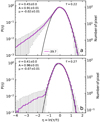 |
Fig. C.3 Panel a: PDF of c-C3H2
using all pixels at a velocity of − 39.7 km s−1.
Panel b: PDF of the same velocity component but using only the pixels
τ∕στ > 3. The results of the Gaussian fit, integral A, dispersion σ, and centre μ, are indicated in the top left corner of each panel. The mean opacity |
C.3 PCA
We investigate here the influence of the noise on the PCA. We perform the PCA for six molecules, using channels that contain only noise. The first two correlation wheels are displayed in Fig. C.4. The power of the first PC is only 30% and the second and third have similar powers of 20.4% and 20.1%. No clear correlation is visible in the wheels. The molecules are randomly distributed in the wheels as expected for noise.
 |
Fig. C.4 Correlation wheels for a PCA performed for six molecules using channels that contain only noise. The percentages in parentheses give the contributions of the PCs to the total variance of the data. |
Appendix D Robustness of PCA
We perform several tests to check the robustness of the principal component analysis applied to our data. First, we test different grid sizes. In the following, a grid size of 1, 2, or 3 means that we use every pixel of the original map, every second pixel, or every third pixel, respectively. With a grid size of 3, some information is lost, because the Nyquist-sampling theorem is not fulfilled. The correlation wheels of the velocity component at vLSR = 24.7 km s−1 are shown in Fig. D.1. The top, middle, and bottom panels correspond to a grid size of 1, 2, and 3, respectively. The percentages in parentheses give the powers of the PCs (their contributions to the total variance of the data). The ellipses around the arrow heads in the middle and bottom panels represent the uncertainties. They were estimated by shifting the grids by one or several pixels. To allow comparison of the PCs resulting from the different starting points of the grid, we realigned them. We chose the first PCA made in the grid sample to fix the signs of the PCs. We changed the signs of the PCs of the other grids to match these signs. We adopted this procedure following Babamoradi et al. (2013). The correlation wheels shown in the top and middle panels are very similar. We conclude that the PCA results do not depend much on the size of the gris and its starting position, provided the Nyquist-sampling condition is met. However, with a grid size of 3 (bottom panels), the uncertainties become larger and the PCA results start to depend significantly on the starting position of the grid.
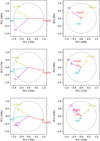 |
Fig. D.1 Correlation wheels for the velocity component at vLSR = 24.7 km s−1. The percentages in parentheses give the contributions of the PCs to the total variance of the data. The top, middle, and bottom panels represent a grid size of 1, 2, and 3, respectively. The ellipses around the arrow heads in the middle and bottom panels show the uncertainties estimated by shifting the grids. |
We investigate in Fig. D.2 the impact of removing one molecule on the PCA results. We show the first correlation wheels at vLSR = 24.7 km s−1 for grid size 2 in four cases, each one corresponding to one of the four molecules being removed. As long as methanol is used, the PC coefficients are similar to those in Fig. D.1. When methanol is excluded, the PC coefficients change significantly and the power of the first PC is reduced. This means that methanol has a dominant structure for this velocity component.
 |
Fig. D.2 First correlation wheels for the velocity component at vLSR = 24.7 km s−1 for grid size 2. Each panel shows the results of the PCA after removing one of the four molecules used in the middle left panel of Fig. D.1. |
We investigate in Fig. D.3 the impact of excluding some pixels on the PCA results. We show the first and second correlation wheels for the velocity component at vLSR = 24.7 km s−1 after excluding 40 pixels (top panels) and 80 pixels (bottom panels). These pixels were chosen randomly and we computed the PCA for 1000 realisations. The ellipses in Fig. D.3 correspond to the dispersion of these 1000 realisations. The results are similar to those in Fig. D.1, except for the molecules with small (< 0.5) PC coefficients.
 |
Fig. D.3 Correlation wheels for PCs at vLSR = 24.7 km s−1 for grid size1 as in Fig. D.1. The first two wheels displayed in the upper panels show the results from the PCA excluding 40 pixels. The wheels in the lower panels result from excluding 80 pixels. The ellipses around the arrow headsshow the uncertainties. |
Altogether the PCA seems to be robust to all these tests for the velocity component at 24.7 km s−1, for which the first principal component contains most of the variance of the data.
Appendix E Spectra
The EMoCA spectra of the 12 investigated molecules towards K4 and the peak of the shell of K6 are shown in Fig. E.1.
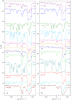 |
Fig. E.1 Spectra of the 12 investigated molecules towards K4 (panel a) and the peak of the shell of K6 (panel b). The spectra are shifted vertically by the amount indicated on the right. |
Appendix F Opacity maps
The opacity and signal-to-noise ratio maps of all molecules except c-C3H2 are shown in Figs. F.1–F.22.
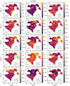 |
Fig. F.1 Same as Fig. 6, but for H13CO+. In this figure and the following ones, blue pixels represent pixels that were masked because the absorption is too optically thick. |
Appendix G Two-point auto-correlation functions
The two-point auto-correlation functions as a function of angular distance are shown in Figs. G.1–G.10 for all molecules except for c-C3H2 and H13CO+. The two-point auto-correlation functions as a function of physical distance are shown in Figs. G.11–G.18 for the eight strongest molecules (c-C3H2, H13CO+, 13CO, CS, SO, SiO, HNC, and CH3OH).
 |
Fig. G.11 Panels a–d: two-point auto-correlation functions C(r) as a functionof physical distance r for the velocity components traced with c-C3H2. The points give the mean values of the 1000 realisations and the colour-shaded regions represent the standard deviations (1σ). The centroidLSR velocities of the clouds are indicated in km s−1 at the top of each panel. |
Appendix H Analysis of two-point auto-correlation functions
We analyse here the two-point auto-correlation functions of all molecules except the ones of SiO and SO which are analysed in Sect. 4.4. c-C3H2 and HNC are detected in all investigated velocity components and trace structures that are more extended than the investigated area (≳ 15′′) for all components but one, at − 93.7 km s−1, for which the size derived from c-C3H2 is ~ 11′′. This component is one of the noisiest for this molecule (with peak S/N below 7) so it is unclear whether this smaller size is significant compared to the other components, especially because the size traced with HNC (14.4′′) is very close to the size of the investigated area. We conclude that c-C3H2 and HNC trace structures that are more extended than ~ 15′′ for all clouds, which corresponds to physical sizes between 0.08 pc in the nearby Sagittarius arm and 0.5 pc in the GC.
13CO and CS also show structures that have sizes larger than (≳ 15′′) or similar to (~ 13–15′′) the size of the field of view. The only exceptions are the component at − 2.7 km s−1 for 13CO and the one at − 48.1 km s−1 for CS. In the former case, the two-point auto-correlation function drops just below the significance threshold at 6′′, but increases above this threshold at larger separations and drops below it again for sizes larger than 10.′′8 (see Fig. G.1). The corresponding opacity map (see Fig. F.3) shows two compact clumps at (6.′′5, 0.5′′) and (9.′′5, 10′′), hence with a separation of 10′′, but one has a S/N below 3 so it may be a noise artefact and the correlation at larger pixel separation may not be real. In the case of CS, the exception concerns the noisiest component, with a peak S/N below 6. The correlation function drops below the significance threshold at 4.′′ 8, but increases above it again at ~ 10′′ (see Fig. G.2). However, it remains close to the significance threshold so its shape is not well constrained. Therefore, overall, 13CO and CS trace structures that are more extended than or nearly as extended as the field of view, like c-C3H2 and HNC.
H13CO+ traces structures with similar extent as the previous tracers. Four exceptions occur, with very small sizes of 2–3′′ or unresolved. All have low S/N in their opacity maps, with a peak S/N below 6 for the component at 31.1 km s−1 and below 5 for the other three components. The sensitivity of our data is therefore not sufficient to characterise the structures traced by H13CO+ for these four components.
CH3OH and HC15N behave in the same way: all components with a peak S/N higher than 5 in their opacity maps, reveal structures that are more extended than the field of view, or at least have sizes larger than 13′′ and 11′′, respectively.
Only six and three components traced by C34S and 13CS, respectively, have a peak S/N in their opacity map higher than 5 (Figs. F.8 and F.10). Most of them trace extended structures of size similar to the field of view (Figs. F.7 and F.9). The 17.7 km s−1 component of C34S and the − 105.9 km s−1 component of 13CS have smaller Δrmax but their peak S/N is barely above 5. The sensitivity of our data is not high enough to characterise the structures of the other velocity components on the basis of these tracers. Because C34S and 13CS are expected to be present in the same regions as CS, that traces extended structures, they clearly show that tracers with a limited sensitivity are not appropriate to constrain the underlying cloud structure. This should be kept in mind when analysing the two-point auto-correlation functions of the other molecules that have low S/N. The case of HN13C is very similar to C34S and 13CS. Only five components have a peak S/N in their opacity map higher than 5 (Fig. F.18). Twoof them trace extended structures and two of them have small or unresolved Δrmax but with a peak S/N barely above 5. The only exception is the component at 2.5 km s−1, with a correlation length of 7′′ and a peak S/N of ~11 in its opacity map. For this velocity component, the main isotopologue, HNC, traces an extended structure with a correlation length larger than the field of view so the shorter correlation length derived from HN13C results from a lack of sensitivity of our data.
Appendix I Probability distribution functions
The PDFs of all molecules but c-C3H2 are shown in Figs. I.1–I.11. The results of the Gaussian fits to the PDFs are shown in Fig. I.12 and I.13, and listed in Tables I.2 and I.3.
Number of Gaussians fitted to the PDF.
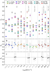 |
Fig. I.12 Panel a: widths of the Gaussians fitted to the PDFs of all molecules for 15 velocity components, roughly sorted by their distance to the Galactic centre. Panel b: mean (left) and median (right) values for each velocity component. Panel c: mean (left) and median (right) values for each sub-sample of clouds, from left to right: Galactic centre, 3 kpc arm, 4 kpc arm, Scutum arm, Sagittarius arm. The uncertainties represent the standard deviation for the mean and the corresponding percentiles for the median. The dashed line in panels b and c marks the mean value of all data points shown in panel a. Velocity components belonging to Category I and II are coloured in grey and black, respectively. |
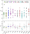 |
Fig. I.13 Panel a: widths of the Gaussians fitted to the PDFs of 15 velocity components sorted by molecule. Panel b: mean (left) and median (right) values for each molecule. The uncertainties represent the standard deviation for the mean and the corresponding percentiles for the median. The dashed line marks the mean value for all components (see Fig. I.12). |
Mean ( ) and median (
 ) widths of the Gaussians fitted to PDFs for each velocity component.
Mean ( ) and median (
 ) dispersion of the PDFs of the molecules.
Appendix J Maps and coefficients of PCA
The principal components and principal component coefficients for the investigated velocities except for vLSR = 24.7 km s−1 are shown in Figs. J.1–J.10.
Appendix K Mopra maps and spectra
We show here channel maps of four velocity components seen in 13CO 1–0 emission with Mopra, and the averaged Mopra emission spectra of HNC 1–0 and CS 2–1 towards Sgr B2.
 |
Fig. K.1 Same as Fig. 22, but for 13CO 1–0 at 11 km s−1 (panel a), − 41 km s−1 (panel b), − 83 km s−1 (panel c), and − 106 km s−1 (panel d). |
Appendix L RADEX models
Results of our RADEX calculations for HNC 1–0, CS 2–1, and 13CO 1–0 are shown in Figs L.1–L.3.
 |
Fig. L.3 Same as Fig. 25, but for 13CO 1–0. The dashed lines indicate the main beam temperature measured for vLSR = −83 km s−1. |
Appendix M Nature of l.o.s. clouds
A modified version of Fig. 2 of Qin et al. (2010) is plotted in Fig. M.1 after correcting the H2 column densities for the non-uniform abundance profile of HCO+ discussed in Sect. 5.1. The column densities of c-C3H2 and H2 calculated from HCO+ are plotted against each other in Fig. M.2. The column densities of CCH and c-C3H2 are plotted against each other in Fig. M.3.
 |
Fig. M.1 Based on Fig. 2 of Qin et al. (2010). We rescaled the H2 values, which they derived from HCO+ assuming a uniform abundance, using the HCO+ abundance profile discussed in Sect. 5.1. The CH column densities in the translucent regime now follow the same correlation with H2 as derived for diffuse clouds by Sheffer et al. (2008). |
 |
Fig. M.2 Same as Fig. 26, but for c-C3H2. The blue cross represents the translucent cloud TMC-1 (Liszt et al. 2018). |
 |
Fig. M.3 Same as Fig. 26, but CCH plotted against c-C3H2. The black line represents a linear fit using only data of diffuse molecular clouds (Godard et al. 2010). |
References
- Ando, R., Kohno, K., Tamura, Y., et al. 2016, PASJ, 68, 6 [NASA ADS] [CrossRef] [Google Scholar]
- Arnett, W. D. 1971, ApJ, 166, 153 [NASA ADS] [CrossRef] [Google Scholar]
- Babamoradi, H., van den Berg, F., & Rinnan, A. 2013, Chemometr. Intell. Lab. Syst., 120, 97 [CrossRef] [Google Scholar]
- Belloche, A., Müller, H. S. P., Menten, K. M., Schilke, P., & Comito, C. 2013, A&A, 559, A47 [NASA ADS] [CrossRef] [EDP Sciences] [Google Scholar]
- Belloche, A., Müller, H. S. P., Garrod, R. T., & Menten, K. M. 2016, A&A, 587, A91 [NASA ADS] [CrossRef] [EDP Sciences] [Google Scholar]
- Bogey, M., Demuynck, C., & Destombes, J. L. 1982, J. Mol. Spectr., 95, 35 [NASA ADS] [CrossRef] [Google Scholar]
- Bonfand, M., Belloche, A., Menten, K. M., Garrod, R. T., & Müller, H. S. P. 2017, A&A, 604, A60 [NASA ADS] [CrossRef] [EDP Sciences] [Google Scholar]
- Botschwina, P., Horn, M., Flügge, J., & Seeger, S. 1993, J. Chem. Soc. Faraday Trans., 89, 2219 [CrossRef] [Google Scholar]
- Cazzoli, G., Puzzarini, C., & Lapinov, A. V. 2004, ApJ, 611, 615 [NASA ADS] [CrossRef] [Google Scholar]
- Cazzoli, G., Puzzarini, C., & Gauss, J. 2005, ApJS, 159, 181 [NASA ADS] [CrossRef] [Google Scholar]
- Corby, J. F., Jones, P. A., Cunningham, M. R., et al. 2015, MNRAS, 452, 3969 [NASA ADS] [CrossRef] [Google Scholar]
- Corby, J. F., McGuire, B. A., Herbst, E., & Remijan, A. J. 2018, A&A, 610, A10 [NASA ADS] [CrossRef] [EDP Sciences] [Google Scholar]
- Cox, P., Guesten, R., & Henkel, C. 1988, A&A, 206, 108 [NASA ADS] [Google Scholar]
- Dumouchel, F., Faure, A., & Lique, F. 2010, MNRAS, 406, 2488 [NASA ADS] [CrossRef] [Google Scholar]
- Endres, C. P., Schlemmer, S., Schilke, P., Stutzki, J., & Müller, H. S. P. 2016, J. Mol. Spectr., 327, 95 [NASA ADS] [CrossRef] [Google Scholar]
- Federrath, C., & Klessen, R. S. 2013, ApJ, 763, 51 [NASA ADS] [CrossRef] [Google Scholar]
- Federrath, C., Klessen, R. S., & Schmidt, W. 2008, ApJ, 688, L79 [NASA ADS] [CrossRef] [Google Scholar]
- Federrath, C., Roman-Duval, J., Klessen, R. S., Schmidt, W., & Mac Low, M.-M. 2010, A&A, 512, A81 [NASA ADS] [CrossRef] [EDP Sciences] [Google Scholar]
- Flower, D. R. 1999, MNRAS, 305, 651 [NASA ADS] [CrossRef] [Google Scholar]
- Fuente, A., Navarro, D., Caselli, P., et al. 2019, A&A, accepted [arXiv:1809.04978] [Google Scholar]
- Gardner, F. F., & Whiteoak, J. B. 1982, MNRAS, 199, 23P [NASA ADS] [CrossRef] [Google Scholar]
- Garwood, R. W., & Dickey, J. M. 1989, ApJ, 338, 841 [NASA ADS] [CrossRef] [Google Scholar]
- Gaume, R. A., Claussen, M. J., de Pree, C. G., Goss, W. M., & Mehringer, D. M. 1995, ApJ, 449, 663 [NASA ADS] [CrossRef] [Google Scholar]
- Gerin, M., de Luca, M., Black, J., et al. 2010a, A&A, 518, L110 [NASA ADS] [CrossRef] [EDP Sciences] [Google Scholar]
- Gerin, M., de Luca, M., Goicoechea, J. R., et al. 2010b, A&A, 521, L16 [NASA ADS] [CrossRef] [EDP Sciences] [Google Scholar]
- Gerin, M., Kaźmierczak, M., Jastrzebska, M., et al. 2011, A&A, 525, A116 [NASA ADS] [CrossRef] [EDP Sciences] [Google Scholar]
- Giannetti, A., Leurini, S., Wyrowski, F., et al. 2017, A&A, 603, A33 [NASA ADS] [CrossRef] [EDP Sciences] [Google Scholar]
- Godard, B., Falgarone, E., Gerin, M., Hily-Blant, P., & de Luca, M. 2010, A&A, 520, A20 [NASA ADS] [CrossRef] [EDP Sciences] [Google Scholar]
- Goorvitch, D. 1994, ApJS, 95, 535 [NASA ADS] [CrossRef] [Google Scholar]
- Gottlieb, C. A., Myers, P. C., & Thaddeus, P. 2003, ApJ, 588, 655 [NASA ADS] [CrossRef] [Google Scholar]
- Gratier, P., Bron, E., Gerin, M., et al. 2017, A&A, 599, A100 [NASA ADS] [CrossRef] [EDP Sciences] [Google Scholar]
- Greaves, J. S. 1995, MNRAS, 273, 918 [NASA ADS] [CrossRef] [Google Scholar]
- Greaves, J. S., & Williams, P. G. 1994, A&A, 290, 259 [NASA ADS] [Google Scholar]
- Greaves, J. S., White, G. J., Ohishi, M., Hasegawa, T., & Sunada, K. 1992, A&A, 260, 381 [NASA ADS] [Google Scholar]
- Halfen, D. T., Woolf, N. J., & Ziurys, L. M. 2017, ApJ, 845, 158 [NASA ADS] [CrossRef] [Google Scholar]
- Heyer, M. H., & Peter Schloerb, F. 1997, ApJ, 475, 173 [NASA ADS] [CrossRef] [Google Scholar]
- Hieret, C. O. 2005, Absorption Studies along the Line of Sight towards Sgr B2(M), diploma thesis, Rheinische Friedrich-Wilhelms-Universität Bonn: Bonn, Germany [Google Scholar]
- Huettemeister, S., Wilson, T. L., Mauersberger, R., et al. 1995, A&A, 294, 667 [NASA ADS] [Google Scholar]
- Jones, P. A., Burton, M. G., Cunningham, M. R., et al. 2008, MNRAS, 386, 117 [NASA ADS] [CrossRef] [Google Scholar]
- Kauffmann, J., Bertoldi, F., Bourke, T. L., Evans, II, N. J., & Lee, C. W. 2008, A&A, 487, 993 [NASA ADS] [CrossRef] [EDP Sciences] [Google Scholar]
- Klessen, R. S. 2000, ApJ, 535, 869 [NASA ADS] [CrossRef] [Google Scholar]
- Kritsuk, A. G., Norman, M. L., Padoan, P., & Wagner, R. 2007, ApJ, 665, 416 [NASA ADS] [CrossRef] [Google Scholar]
- Ladd, N., Purcell, C., Wong, T., & Robertson, S. 2005, PASA, 22, 62 [NASA ADS] [CrossRef] [Google Scholar]
- Lang, C. C., Goss, W. M., Cyganowski, C., & Clubb, K. I. 2010, ApJS, 191, 275 [NASA ADS] [CrossRef] [Google Scholar]
- Lique, F., Spielfiedel, A., & Cernicharo, J. 2006, A&A, 451, 1125 [NASA ADS] [CrossRef] [EDP Sciences] [Google Scholar]
- Lis, D. C., & Goldsmith, P. F. 1990, ApJ, 356, 195 [NASA ADS] [CrossRef] [Google Scholar]
- Lis, D. C., Phillips, T. G., Goldsmith, P. F., et al. 2010, A&A, 521, L26 [NASA ADS] [CrossRef] [EDP Sciences] [Google Scholar]
- Liszt, H., & Gerin, M. 2018, A&A, 610, A49 [NASA ADS] [CrossRef] [EDP Sciences] [Google Scholar]
- Liszt, H. S., & Pety, J. 2016, ApJ, 823, 124 [NASA ADS] [CrossRef] [Google Scholar]
- Liszt, H. S., Pety, J., & Lucas, R. 2010, A&A, 518, A45 [NASA ADS] [CrossRef] [EDP Sciences] [Google Scholar]
- Liszt, H., Sonnentrucker, P., Cordiner, M., & Gerin, M. 2012, ApJ, 753, L28 [NASA ADS] [CrossRef] [Google Scholar]
- Liszt, H., Gerin, M., Beasley, A., & Pety, J. 2018, ApJ, 856, 151 [NASA ADS] [CrossRef] [Google Scholar]
- Liu, S.-Y., & Snyder, L. E. 1999, ApJ, 523, 683 [NASA ADS] [CrossRef] [Google Scholar]
- Lucas, R., & Liszt, H. S. 1996, in Molecules in Astrophysics: Probes & Processes, ed. E. F. van Dishoeck, IAU Symp., 178, 421 [NASA ADS] [Google Scholar]
- Lucas, R., & Liszt, H. S. 1999, in The Physics and Chemistry of the Interstellar Medium, eds. V. Ossenkopf, J. Stutzki, & G. Winnewisser (Germany: GCA-Verlag Herdecke) [Google Scholar]
- Lucas, R., & Liszt, H. S. 2000, A&A, 358, 1069 [NASA ADS] [Google Scholar]
- Magnani, L., Larosa, T. N., & Shore, S. N. 1993, ApJ, 402, 226 [NASA ADS] [CrossRef] [Google Scholar]
- Maret, S., Hily-Blant, P., Pety, J., Bardeau, S., & Reynier, E. 2011, A&A, 526, A47 [NASA ADS] [CrossRef] [EDP Sciences] [Google Scholar]
- Menten, K. M., Wyrowski, F., Belloche, A., et al. 2011, A&A, 525, A77 [NASA ADS] [CrossRef] [EDP Sciences] [Google Scholar]
- Milam, S. N., Savage, C., Brewster, M. A., Ziurys, L. M., & Wyckoff, S. 2005, ApJ, 634, 1126 [NASA ADS] [CrossRef] [Google Scholar]
- Mills, E. A. C., Corby, J., Clements, A. R., et al. 2018, ApJ, 869, 121 [NASA ADS] [CrossRef] [Google Scholar]
- Monje, R. R., Emprechtinger, M., Phillips, T. G., et al. 2011, ApJ, 734, L23 [NASA ADS] [CrossRef] [Google Scholar]
- Müller, H. S. P., Thorwirth, S., Roth, D. A., & Winnewisser, G. 2001, A&A, 370, L49 [NASA ADS] [CrossRef] [EDP Sciences] [Google Scholar]
- Müller, H. S. P., Menten, K. M., & Mäder, H. 2004, A&A, 428, 1019 [NASA ADS] [CrossRef] [EDP Sciences] [Google Scholar]
- Müller, H. S. P., Schlöder, F., Stutzki, J., & Winnewisser, G. 2005, J. Mol. Struct., 742, 215 [NASA ADS] [CrossRef] [Google Scholar]
- Müller, H. S. P., Spezzano, S., Bizzocchi, L., et al. 2013, J. Phys. Chem. A, 117 [Google Scholar]
- Neill, J. L., Bergin, E. A., Lis, D. C., et al. 2014, ApJ, 789, 8 [NASA ADS] [CrossRef] [Google Scholar]
- Neufeld, D. A., Ashby, M. L. N., Bergin, E. A., et al. 2000, ApJ, 539, L111 [NASA ADS] [CrossRef] [Google Scholar]
- Neufeld, D. A., Godard, B., Gerin, M., et al. 2015, A&A, 577, A49 [NASA ADS] [CrossRef] [EDP Sciences] [Google Scholar]
- Ossenkopf-Okada, V., Csengeri, T., Schneider, N., Federrath, C., & Klessen, R. S. 2016, A&A, 590, A104 [NASA ADS] [CrossRef] [EDP Sciences] [Google Scholar]
- Padoan, P., Nordlund, A., & Jones, B. J. T. 1997, MNRAS, 288, 145 [NASA ADS] [CrossRef] [Google Scholar]
- Passot, T., & Vázquez-Semadeni, E. 1998, Phys. Rev. E, 58, 4501 [NASA ADS] [CrossRef] [Google Scholar]
- Patil, A., Huard, D., & Fonnesbeck, C. 2010, J. Stat. Softw., 35, 1 [CrossRef] [EDP Sciences] [Google Scholar]
- Pedregosa, F., Varoquaux, G., Gramfort, A., et al. 2011, J. Mach. Learn. Res., 12, 2825 [Google Scholar]
- Pety, J., Schinnerer, E., Leroy, A. K., et al. 2013, ApJ, 779, 43 [NASA ADS] [CrossRef] [Google Scholar]
- Pickett, H. M., Poynter, R. L., Cohen, E. A., et al. 1998, J. Quant. Spectr. Rad. Transf., 60, 883 [NASA ADS] [CrossRef] [Google Scholar]
- Polehampton, E. T., Baluteau, J.-P., & Swinyard, B. M. 2005, A&A, 437, 957 [NASA ADS] [CrossRef] [EDP Sciences] [Google Scholar]
- Powell, M. J. D. 1964, Comput. J., 7, 155 [CrossRef] [MathSciNet] [Google Scholar]
- Qin, S.-L., Schilke, P., Comito, C., et al. 2010, A&A, 521, L14 [NASA ADS] [CrossRef] [EDP Sciences] [Google Scholar]
- Reid, M. J., Menten, K. M., Brunthaler, A., et al. 2014, ApJ, 783, 130 [Google Scholar]
- Sánchez-Monge, Á., Schilke, P., Schmiedeke, A., et al. 2017, A&A, 604, A6 [NASA ADS] [CrossRef] [EDP Sciences] [Google Scholar]
- Sawada, T., Hasegawa, T., Sugimoto, M., Koda, J., & Handa, T. 2012, ApJ, 752, 118 [NASA ADS] [CrossRef] [Google Scholar]
- Saykally, R. J., Szanto, P. G., Anderson, T. G., & Woods, R. C. 1976, ApJ, 204, L143 [NASA ADS] [CrossRef] [Google Scholar]
- Schmid-Burgk, J., Muders, D., Müller, H. S. P., & Brupbacher-Gatehouse, B. 2004, A&A, 419, 949 [NASA ADS] [CrossRef] [EDP Sciences] [Google Scholar]
- Schneider, N., André, P., Könyves, V., et al. 2013, ApJ, 766, L17 [NASA ADS] [CrossRef] [Google Scholar]
- Schneider, N., Csengeri, T., Klessen, R. S., et al. 2015a, A&A, 578, A29 [NASA ADS] [CrossRef] [EDP Sciences] [Google Scholar]
- Schneider, N., Ossenkopf, V., Csengeri, T., et al. 2015b, A&A, 575, A79 [NASA ADS] [CrossRef] [EDP Sciences] [Google Scholar]
- Schöier, F. L., van der Tak, F. F. S., van Dishoeck, E. F., & Black, J. H. 2005, A&A, 432, 369 [NASA ADS] [CrossRef] [EDP Sciences] [Google Scholar]
- Sheffer, Y., Rogers, M., Federman, S. R., et al. 2008, ApJ, 687, 1075 [NASA ADS] [CrossRef] [Google Scholar]
- Shore, S. N., Magnani, L., LaRosa, T. N., & McCarthy, M. N. 2003, ApJ, 593, 413 [NASA ADS] [CrossRef] [Google Scholar]
- Shore, S. N., Larosa, T. N., Chastain, R. J., & Magnani, L. 2006, A&A, 457, 197 [NASA ADS] [CrossRef] [EDP Sciences] [Google Scholar]
- Shore, S. N., Larosa, T. N., Magnani, L., Chastain, R. J., & Costagliola, F. 2007, in Triggered Star Formation in a Turbulent ISM, eds. B. G. Elmegreen & J. Palous, IAU Symp., 237, 17 [NASA ADS] [Google Scholar]
- Snow, T. P., & McCall, B. J. 2006, ARA&A, 44, 367 [NASA ADS] [CrossRef] [Google Scholar]
- Spezzano, S., Tamassia, F., Thorwirth, S., et al. 2012, ApJS, 200, 1 [NASA ADS] [CrossRef] [Google Scholar]
- Spezzano, S., Caselli, P., Bizzocchi, L., Giuliano, B. M., & Lattanzi, V. 2017, A&A, 606, A82 [NASA ADS] [CrossRef] [EDP Sciences] [Google Scholar]
- Suutarinen, A., Geppert, W. D., Harju, J., et al. 2011, A&A, 531, A121 [NASA ADS] [CrossRef] [EDP Sciences] [Google Scholar]
- Thiel, V., Belloche, A., Menten, K. M., Garrod, R. T., & Müller, H. S. P. 2017, A&A, 605, L6 [NASA ADS] [CrossRef] [EDP Sciences] [Google Scholar]
- Tiemann, E. 1974, J. Mol. Spectr., 51, 316 [NASA ADS] [CrossRef] [Google Scholar]
- Tremblin, P., Schneider, N., Minier, V., et al. 2014, A&A, 564, A106 [NASA ADS] [CrossRef] [EDP Sciences] [Google Scholar]
- van der Tak, F. F. S., Black, J. H., Schöier, F. L., Jansen, D. J., & van Dishoeck E. F. 2007, A&A, 468, 627 [NASA ADS] [CrossRef] [EDP Sciences] [Google Scholar]
- van der Tak, F. F. S., Müller, H. S. P., Harding, M. E., & Gauss, J. 2009, A&A, 507, 347 [NASA ADS] [CrossRef] [EDP Sciences] [Google Scholar]
- Whiteoak, J. B., & Gardner, F. F. 1978, Proc. Astron. Soc. Aust., 3, 266 [NASA ADS] [CrossRef] [Google Scholar]
- Wiesemeyer, H., Güsten, R., Heyminck, S., et al. 2016, A&A, 585, A76 [NASA ADS] [CrossRef] [EDP Sciences] [Google Scholar]
- Wirström, E. S., Bergman, P., Black, J. H., et al. 2010, A&A, 522, A19 [NASA ADS] [CrossRef] [EDP Sciences] [Google Scholar]
- Yang, B., Stancil, P. C., Balakrishnan, N., & Forrey, R. C. 2010, ApJ, 718, 1062 [NASA ADS] [CrossRef] [Google Scholar]
All Tables
Velocity ranges and associated locations of the clouds along the line of sight to Sgr B2.
Velocities and localisation of the diffuse and translucent molecular clouds detected with c-C3 H2 along the line of sight to Sgr B2, excluding Category III and the envelope of Sgr B2.
Angular sizes of cloud structures derived from two-point auto-correlation functions.
Physical sizes of cloud structures derived from two-point auto-correlation functions.
Mean ( ) and median (
 ) widths directly computed from the PDFs for each velocity component.
PDF widths and parameters describing the turbulence for all investigated molecules.
PDF widths, linewidths, Mach numbers, and parameters describing the turbulence of the velocity components.
H2 column densities and visual extinctions derived from the HCO+ column densities determined in the ALMA spectrum in the direction of K4.
Mean ( ) and median (
 ) widths of the Gaussians fitted to PDFs for each velocity component.
All Figures
 |
Fig. 1 ALMA continuum map of Sgr B2(N) at 85 GHz. The black contour lines show the flux density levels at 3σ, 6σ, 12σ, and 24σ and the dotted ones mark −3σ, with σ the rms noise level of 5.4 mJy beam−1. The black crosses mark the positions of the hot cores Sgr B2(N1) and Sgr B2(N2), the white cross the phase centre (EQ J2000: 17h47m19.87s, −28°22′16′′), and the white triangles the ultra compact HII region K4 and the peak in the shell of the HII region K6 (Gaume et al. 1995). The white ellipse in the lower right corner is the synthesised beam. The white contour encloses the region selected for the analysis of the absorption features, for the particular case of ortho c-C3 H2. The pixel size in this image is 0.′′3. |
| In the text | |
 |
Fig. 2 Sketch of the Milky Way and the spiral arms along the line of sight to Sgr B2 (based on Greaves & Williams 1994). The velocity ranges of the diffuse and translucent clouds are indicated in km s−1. |
| In the text | |
 |
Fig. 3 Panel a: ALMA spectrum of ortho c-C3H2 21,2 − 10,1 at 85338.896 MHz towards the UCHII region K4 (Gaume et al. 1995). The spectrum in magenta is the synthetic spectrum obtained with MCWeeds. The blue lines show the central velocities of the fitted components. The dotted line represents the continuum level and the dashed line marks the 4σ line detection threshold. The grey area marks the velocity range of the envelope of Sgr B2 (vLSR > 42 km s−1). Panel b: residuals, that is the difference between the observed and synthetic spectra. The dashed lines indicate the − 4σ level. The spectrum is corrected for the primary beam attenuation. |
| In the text | |
 |
Fig. 4 Panel a: number of velocity components found with ortho c-C3H2 in the selected field as a function of centroid velocity. The bin width is one channel, 1.74 km s−1. Panel b: distribution of linewidths. Panel c: distribution of ortho c-C3H2 column densities. The velocity ranges are colour coded in the background of every panel (see Table 1 for references). |
| In the text | |
 |
Fig. 5 Panel a: distribution of column densities as a function of linewidth. Panel b: number of components as a function of column density. Panel c: distribution of column densities divided by linewidth as a function of linewidth. Panel d: number of components as a function of column density divided by linewidth. Panel e: number of velocity components as a function of linewidth. The bin width is 0.5 km s−1. In all panels the two categories of line-of-sight clouds are coloured in yellow (Category I) and magenta (Category II), the clouds at about 50 km s−1 in cyan (Category III), and the components tracing the diffuse envelope of Sgr B2 in blue. In panels b, d, and e, the black histogram represents the full sample of detected components. |
| In the text | |
 |
Fig. 6 Opacity maps of c-C3H2 21,2 –10,1 for all 15 investigated velocity components. In each panel, the velocity of the channel is given in km s−1 in the bottom left corner, the beam (HPBW) is shown as an ellipse in the upper left corner, and an approximate physical scale for the assumed distance of the cloud (see Table 3) is indicated in the bottom right corner. A star in the upper right corner marks the components with a maximum S/N τ/στ smaller than 5 (see Fig. 7). The equatorial offsets are relative to the phase centre. |
| In the text | |
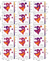 |
Fig. 7 Same as Fig. 6 but for the S/N τ∕στ of c-C3 H2 21,2 –10,1. |
| In the text | |
 |
Fig. 8 Panels a–d: two-point auto-correlation functions C(r) as a functionof pixel separation r for the velocity components traced with c-C3H2. The points give the mean values of the 1000 realisations and the colour-shaded regions represent the standard deviations (1σ). The centroidLSR velocities of the clouds are indicated in km s−1 at the top of each panel. Panel e: S/N of the two-point auto-correlation functions shown in panels a–d. The S/N levels of ±3, ± 4 and ± 5 are highlighted in shades of grey. The colours and symbols are the same as in panels a–d. The vertical dashed line shows the size of the beam (HPBW). The area below and left of the magenta line represents the area where the two-point auto-correlation functions are not significant. |
| In the text | |
 |
Fig. 9 Same as Fig. 8, but for H13CO+. |
| In the text | |
 |
Fig. 10 Probability distribution functions P(η) of the velocity components probed with c-C3H2. The velocity of the component is indicated at the bottom of each panel in km s−1. The right y-axis indicates thenumber of pixels counted in each bin. The mean opacity |
| In the text | |
 |
Fig. 11 Distribution of standard deviations (width) of the PDFs of all molecules for all 15 velocity components.
N
gives the total number of PDFs used for each histogram, |
| In the text | |
 |
Fig. 12 Same as Fig. 11 but for the sub-sample containing only c-C3 H2, H13CO+, 13CO, CS, and HNC. |
| In the text | |
 |
Fig. 13 Panel a: widths of the PDFs of all molecules for the 15 velocity components, roughly sorted by their distance to the Galactic centre. Panel b: mean (left) and median (right) values for each velocity component. Panel c: mean (left) and median(right) values for each sub-sample of clouds, from left to right: Galactic centre, 3 kpc arm, 4 kpc arm, Scutum arm, Sagittarius arm. The uncertainties represent the standard deviation for the mean and the corresponding percentiles for the median. The dashed line in each panel marks the mean value of all data points shown in panel a. Velocity components belonging to Category I and II are coloured in grey and black, respectively. |
| In the text | |
 |
Fig. 14 Panel a: widths of the PDFs of 15 different velocity components along the line of sight sorted by molecule. Panel b: mean (left) and median (right) values for each molecule. The uncertainties represent the standard deviation for the mean and the corresponding percentiles for the median. The dashed line in both panels marks the mean and the median value for all components (see Fig. 11). |
| In the text | |
 |
Fig. 15 Forcing parameter b plotted against ζ for Tkin = 40 K for all15 velocity components. The different velocities are colour coded and given in km s −1. The magenta line represents the function derived from hydrodynamic simulations by Federrath et al. (2010). |
| In the text | |
 |
Fig. 16 Panel a: forcing parameter b of eight molecules, assuming Tkin = 40 K for the 15 velocity components roughly sorted by their distance to the Galactic centre. Panel b: mean (left) and median (right) values for each velocity component. Panel c: mean (left) and median (right) values for each sub-sample of clouds, from left to right: Galactic centre, 3 kpc arm, 4 kpc arm, Scutum arm, Sagittarius arm. The uncertainties represent the standard deviation for the mean and the corresponding percentiles for the median. The dashed line in each panel marks the median value of all data points shown in panel a. The velocities of the components belonging to Categories I and II are colouredin grey and black, respectively. |
| In the text | |
 |
Fig. 17 Panel a: forcing parameter b of up to 15 velocity components sorted by molecule and assuming Tkin = 40 K. Panel b: mean (left) and median (right) values for each molecule. The uncertainties represent the standard deviation for the mean and the corresponding percentiles for the median. The dashed line in both panels marks the median value of the sub-sample of molecules used in Fig. 16. |
| In the text | |
 |
Fig. 18 Principal components determined at vLSR = 24.7 km s−1. The colours give the intensity. The absolute value of each PC is normalised to 1 as explained in Sect. 3.8. The percentages in parentheses give the contributions of the PCs to the total variance. |
| In the text | |
 |
Fig. 19 Principal component coefficients determined at vLSR = 24.7 km s−1. The contribution factors of each molecule are normalised such that the sum of the squares is equal to 1. The percentages in parentheses give the contributions of the PCs to the total variance. |
| In the text | |
 |
Fig. 20 Correlation wheels for PCs at vLSR = 24.7 km s−1 (panels a), − 105.9 km s−1 (panels b), 2.0 km s−1 (panels c), 7.3 km s−1 (panels d), 31.6 km s−1 (panels e), and 17.7 km s−1 (panels f). The percentages in parentheses give the contributions of the PCs to the total variance. The ellipses around the arrow heads show the uncertainties estimated from 1000 realisations of the opacity cubes. |
| In the text | |
 |
Fig. 21 ALMA spectra of HCO+ 1–0 and H13CO+ 1–0 (shifted by +4 K) in the direction of K4 in black. The synthetic spectra of HCO+ and H13CO+ computed with Weeds are overplotted in blue and magenta, respectively. |
| In the text | |
 |
Fig. 22 Mopra channel maps in the direction of Sgr B2 at about 14 km s−1 for HCO+ 1–0 (panel a), HNC 1–0 (panel b), and CS 2–1 (panel c) as observed by Jones et al. (2008). In each panel, the white box shows the region selected to calculate the averaged spectrum and the green contour encloses the pixels that were masked to avoid absorption. The white circle in the lower right corner of each panel represents the beam and the cross indicates the position of K4. The pixel size is 12′′. |
| In the text | |
 |
Fig. 23 Mopra average spectrum of HCO+
1–0 towards Sgr B2(N), extracted from the imaging survey of Jones et al. (2008) after excluding pixels with absorption (see Fig. 22). The black and blue spectra were obtained with the broad-band and narrow-band backends, respectively. They are displayed in
|
| In the text | |
 |
Fig. 24 Same as Fig. 23, but for 13CO 1–0. The ALMA spectrum is resampled to the spectral resolution of the Mopra spectrum. The dashed lines mark emission peaks that match well absorption features of the EMoCA spectrum outside the velocity range of the Sgr B2 envelope. |
| In the text | |
 |
Fig. 25 HCO+ 1–0 brightness temperature computed with RADEX as a function of kinetic temperature (x-axis) and H2 density (y-axis), assuming different column densities. In each panel, the solid line corresponds to the level of emission measured in the Mopra spectrum around 14 km s−1 and the dashed line to the upper limit (3σ) over the velocity range from − 110 km s−1 to − 10 km s−1. The solid line is displayed only for the column densities that fall in the range determined from the ALMA absorption map at this velocity and the white star marks the median column density obtained from the ALMA absorption map at this velocity. |
| In the text | |
 |
Fig. 26 Distribution of CCH column densities versus H2 column densities, calculated from HCO+ as described in Sect. 5.1. The filled symbols represent the values obtained for the velocity components detected toward six positions with strong continuum background in the ALMA data. Their equatorial offsets are indicated tothe right. The fainter filling colours are used for the GC components. The red crosses are measurements from Godard et al. (2010) and Gerin et al. (2011) and the black ones from Lucas & Liszt (1996, 2000). The dashed lines are linear fits to the following samples: all data (blue), ALMA data only (black), ALMA GC components only (magenta), and ALMA disk components only (green). The dotted-dashed lines are fits with a slope of unity. The fits results are given in the upper left corner with their uncertainties. The Pearson correlation coefficients r are given onthe right side. The vertical lines highlight the limits between diffuse, translucent, and dense clouds. |
| In the text | |
 |
Fig. C.1 Two-point auto-correlation function C(r) of four different noise channels next to the transition of c-C3H2 as a functionof pixel separation r. The coloured regions around the curves represent the standard deviation of the 1000 realisations of the opacity cube. |
| In the text | |
 |
Fig. C.2 Panel a: S/N of the two-point auto-correlation functions (C(r)∕σC) of 48 noise channels, four per molecule, as a function of pixel separation r. All points at pixel separations smaller than the beam are coloured in purple, the other ones in cyan. The vertical dashed line at 2′′ correspondsto the major axis of the beam. The area above and to the right of the magenta line is the area where the correlation function of a channel containing signal indicates a significant correlation. Panel b: distribution of C∕σC. The regions of S/N smaller than 3, 4, and 5 are highlighted in shades of grey. |
| In the text | |
 |
Fig. C.3 Panel a: PDF of c-C3H2
using all pixels at a velocity of − 39.7 km s−1.
Panel b: PDF of the same velocity component but using only the pixels
τ∕στ > 3. The results of the Gaussian fit, integral A, dispersion σ, and centre μ, are indicated in the top left corner of each panel. The mean opacity |
| In the text | |
 |
Fig. C.4 Correlation wheels for a PCA performed for six molecules using channels that contain only noise. The percentages in parentheses give the contributions of the PCs to the total variance of the data. |
| In the text | |
 |
Fig. D.1 Correlation wheels for the velocity component at vLSR = 24.7 km s−1. The percentages in parentheses give the contributions of the PCs to the total variance of the data. The top, middle, and bottom panels represent a grid size of 1, 2, and 3, respectively. The ellipses around the arrow heads in the middle and bottom panels show the uncertainties estimated by shifting the grids. |
| In the text | |
 |
Fig. D.2 First correlation wheels for the velocity component at vLSR = 24.7 km s−1 for grid size 2. Each panel shows the results of the PCA after removing one of the four molecules used in the middle left panel of Fig. D.1. |
| In the text | |
 |
Fig. D.3 Correlation wheels for PCs at vLSR = 24.7 km s−1 for grid size1 as in Fig. D.1. The first two wheels displayed in the upper panels show the results from the PCA excluding 40 pixels. The wheels in the lower panels result from excluding 80 pixels. The ellipses around the arrow headsshow the uncertainties. |
| In the text | |
 |
Fig. E.1 Spectra of the 12 investigated molecules towards K4 (panel a) and the peak of the shell of K6 (panel b). The spectra are shifted vertically by the amount indicated on the right. |
| In the text | |
 |
Fig. F.1 Same as Fig. 6, but for H13CO+. In this figure and the following ones, blue pixels represent pixels that were masked because the absorption is too optically thick. |
| In the text | |
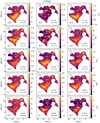 |
Fig. F.2 Same as Fig. 7, but for H13CO+. |
| In the text | |
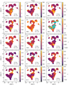 |
Fig. F.3 Same as Fig. 6, but for 13CO. |
| In the text | |
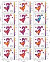 |
Fig. F.4 Same as Fig. 7, but for 13CO. |
| In the text | |
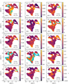 |
Fig. F.5 Same as Fig. 6, but for CS. |
| In the text | |
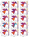 |
Fig. F.6 Same as Fig. 7, but for CS. |
| In the text | |
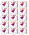 |
Fig. F.7 Same as Fig. 6, but for C34S. |
| In the text | |
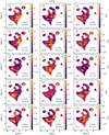 |
Fig. F.8 Same as Fig. 7, but for C34S. |
| In the text | |
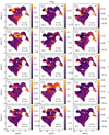 |
Fig. F.9 Same as Fig. 6, but for 13CS. |
| In the text | |
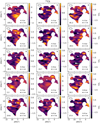 |
Fig. F.10 Same as Fig. 7, but for 13CS. |
| In the text | |
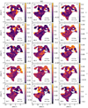 |
Fig. F.11 Same as Fig. 6, but for SO. |
| In the text | |
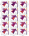 |
Fig. F.12 Same as Fig. 7, but for SO. |
| In the text | |
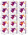 |
Fig. F.13 Same as Fig. 6, but for SiO. |
| In the text | |
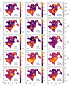 |
Fig. F.14 Same as Fig. 7, but for SiO. |
| In the text | |
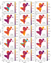 |
Fig. F.15 Same as Fig. 6, but for HNC. |
| In the text | |
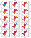 |
Fig. F.16 Same as Fig. 7, but for HNC. |
| In the text | |
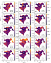 |
Fig. F.17 Same as Fig. 6, but for HN13C. |
| In the text | |
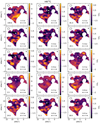 |
Fig. F.18 Same as Fig. 7, but for HN13C. |
| In the text | |
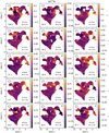 |
Fig. F.19 Same as Fig. 6, but for HC15N. |
| In the text | |
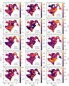 |
Fig. F.20 Same as Fig. 7, but for HC15N. |
| In the text | |
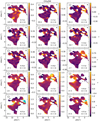 |
Fig. F.21 Same as Fig. 6, but for CH3OH. |
| In the text | |
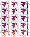 |
Fig. F.22 Same as Fig. 7, but for CH3OH. |
| In the text | |
 |
Fig. G.1 Same as Fig. 8, but for 13CO. |
| In the text | |
 |
Fig. G.2 Same as Fig. 8, but for CS. |
| In the text | |
 |
Fig. G.3 Same as Fig. 8, but for C34S. |
| In the text | |
 |
Fig. G.4 Same as Fig. 8, but for 13CS. |
| In the text | |
 |
Fig. G.5 Same as Fig. 8, but for SO. |
| In the text | |
 |
Fig. G.6 Same as Fig. 8, but for SiO. |
| In the text | |
 |
Fig. G.7 Same as Fig. 8, but for HNC. |
| In the text | |
 |
Fig. G.8 Same as Fig. 8, but for HN13C. |
| In the text | |
 |
Fig. G.9 Same as Fig. 8, but for HC15N. |
| In the text | |
 |
Fig. G.10 Same as Fig. 8, but for CH3OH. |
| In the text | |
 |
Fig. G.11 Panels a–d: two-point auto-correlation functions C(r) as a functionof physical distance r for the velocity components traced with c-C3H2. The points give the mean values of the 1000 realisations and the colour-shaded regions represent the standard deviations (1σ). The centroidLSR velocities of the clouds are indicated in km s−1 at the top of each panel. |
| In the text | |
 |
Fig. G.12 Same as Fig. G.11, but for H13CO+. |
| In the text | |
 |
Fig. G.13 Same as Fig. G.11, but for 13CO. |
| In the text | |
 |
Fig. G.14 Same as Fig. G.11, but for CS. |
| In the text | |
 |
Fig. G.15 Same as Fig. G.11, but for SO. |
| In the text | |
 |
Fig. G.16 Same as Fig. G.11, but for SiO. |
| In the text | |
 |
Fig. G.17 Same as Fig. G.11, but for HNC. |
| In the text | |
 |
Fig. G.18 Same as Fig. G.11, but for CH3OH. |
| In the text | |
 |
Fig. I.1 Same as Fig. 10, but for C34S. |
| In the text | |
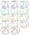 |
Fig. I.2 Same as Fig. 10, but for H13CO+. |
| In the text | |
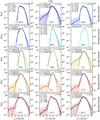 |
Fig. I.3 Same as Fig. 10, but for 13CO. |
| In the text | |
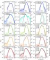 |
Fig. I.4 Same as Fig. 10, but for CS. |
| In the text | |
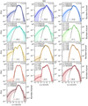 |
Fig. I.5 Same as Fig. 10, but for SiO. |
| In the text | |
 |
Fig. I.6 Same as Fig. 10, but for SO. |
| In the text | |
 |
Fig. I.7 Same as in Fig. 10, but for HN13C. |
| In the text | |
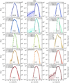 |
Fig. I.8 Same as Fig. 10, but for HNC. |
| In the text | |
 |
Fig. I.9 Same as Fig. 10, but for HC15N. |
| In the text | |
 |
Fig. I.10 Same as Fig. 10, but for CH3OH. |
| In the text | |
 |
Fig. I.11 Same as Fig. 10, but for 13CS. |
| In the text | |
 |
Fig. I.12 Panel a: widths of the Gaussians fitted to the PDFs of all molecules for 15 velocity components, roughly sorted by their distance to the Galactic centre. Panel b: mean (left) and median (right) values for each velocity component. Panel c: mean (left) and median (right) values for each sub-sample of clouds, from left to right: Galactic centre, 3 kpc arm, 4 kpc arm, Scutum arm, Sagittarius arm. The uncertainties represent the standard deviation for the mean and the corresponding percentiles for the median. The dashed line in panels b and c marks the mean value of all data points shown in panel a. Velocity components belonging to Category I and II are coloured in grey and black, respectively. |
| In the text | |
 |
Fig. I.13 Panel a: widths of the Gaussians fitted to the PDFs of 15 velocity components sorted by molecule. Panel b: mean (left) and median (right) values for each molecule. The uncertainties represent the standard deviation for the mean and the corresponding percentiles for the median. The dashed line marks the mean value for all components (see Fig. I.12). |
| In the text | |
 |
Fig. J.1 Same as Fig. 18 vLSR = −105.9 km s−1. |
| In the text | |
 |
Fig. J.2 Same as Fig. 19 but for vLSR = −105.9 km s−1. |
| In the text | |
 |
Fig. J.3 Same as Fig. 18 vLSR = 2.0 km s−1. |
| In the text | |
 |
Fig. J.4 Same as Fig. 19 but for vLSR = 2.0 km s−1. |
| In the text | |
 |
Fig. J.5 Same as Fig. 18 vLSR = 7.3 km s−1. |
| In the text | |
 |
Fig. J.6 Same as Fig. 19 but for vLSR = 7.3 km s−1. |
| In the text | |
 |
Fig. J.7 Same as Fig. 18 vLSR = 31.6 km s−1. |
| In the text | |
 |
Fig. J.8 Same as Fig. 19 but for vLSR = 31.6 km s−1. |
| In the text | |
 |
Fig. J.9 Same as Fig. 18 but for vLSR = 17.7 km s−1. |
| In the text | |
 |
Fig. J.10 Same as Fig. 19 but for vLSR = 17.7 km s−1. |
| In the text | |
 |
Fig. K.1 Same as Fig. 22, but for 13CO 1–0 at 11 km s−1 (panel a), − 41 km s−1 (panel b), − 83 km s−1 (panel c), and − 106 km s−1 (panel d). |
| In the text | |
 |
Fig. K.2 Same as Fig. 23, but for HNC 1–0. |
| In the text | |
 |
Fig. K.3 Same as Fig. 23, but for CS 2–1. |
| In the text | |
 |
Fig. L.1 Same as Fig. 25, but for HNC 1–0. |
| In the text | |
 |
Fig. L.2 Same as Fig. 25, but for CS 2–1. |
| In the text | |
 |
Fig. L.3 Same as Fig. 25, but for 13CO 1–0. The dashed lines indicate the main beam temperature measured for vLSR = −83 km s−1. |
| In the text | |
 |
Fig. M.1 Based on Fig. 2 of Qin et al. (2010). We rescaled the H2 values, which they derived from HCO+ assuming a uniform abundance, using the HCO+ abundance profile discussed in Sect. 5.1. The CH column densities in the translucent regime now follow the same correlation with H2 as derived for diffuse clouds by Sheffer et al. (2008). |
| In the text | |
 |
Fig. M.2 Same as Fig. 26, but for c-C3H2. The blue cross represents the translucent cloud TMC-1 (Liszt et al. 2018). |
| In the text | |
 |
Fig. M.3 Same as Fig. 26, but CCH plotted against c-C3H2. The black line represents a linear fit using only data of diffuse molecular clouds (Godard et al. 2010). |
| In the text | |
Current usage metrics show cumulative count of Article Views (full-text article views including HTML views, PDF and ePub downloads, according to the available data) and Abstracts Views on Vision4Press platform.
Data correspond to usage on the plateform after 2015. The current usage metrics is available 48-96 hours after online publication and is updated daily on week days.
Initial download of the metrics may take a while.


