| Issue |
A&A
Volume 679, November 2023
|
|
|---|---|---|
| Article Number | A88 | |
| Number of page(s) | 19 | |
| Section | Extragalactic astronomy | |
| DOI | https://doi.org/10.1051/0004-6361/202245729 | |
| Published online | 16 November 2023 | |
NGC 2992: Interplay between the multiphase disc, wind, and radio bubbles
1
SISSA, Via Bonomea 265, 34136 Trieste, Italy
e-mail: This email address is being protected from spambots. You need JavaScript enabled to view it.
2
INAF – Osservatorio Astronomico di Trieste, Via G. B. Tiepolo 11, 34143 Trieste, Italy
3
IFPU – Institute for Fundamental Physics of the Universe, Via Beirut 2, 34014 Trieste, Italy
4
INAF – Istituto di Radioastronomia, Italian ARC, Via Piero Gobetti 101, 40129 Bologna, Italy
5
INFN, Sezione di Trieste, Via Valerio 2, Trieste 34127, Italy
6
Dipartimento di Fisica, Università di Trieste, Sezione di Astronomia, Via G. B. Tiepolo 11, 34131 Trieste, Italy
7
Department of Physics, University of Milan Bicocca, Piazza della Scienza 3, 20126 Milano, Italy
8
INAF – Osservatorio Astronomico di Roma, Via di Frascati 33, 00040 Monteporzio Catone, Rome, Italy
9
INAF – OAS Bologna, Via Gobetti 101, 40129 Bologna, Italy
10
ASI – Agenzia Spaziale Italiana, Via del Politecnico snc, 00133 Roma, Italy
11
Dept. of Physics, University of Rome “Tor Vergata”, Via della Ricerca Scientifica 1, 00133 Rome, Italy
12
Dept. of Astronomy, University of Maryland, College Park, MD 20742, USA
13
NASA – Goddard Space Flight Center, Code 662, Greenbelt, MD 20771, USA
14
INFN – Roma Tor Vergata, Via Della Ricerca Scientifica 1, 00133 Rome, Italy
15
Dipartimento di Fisica e Astronomia, Università di Firenze, Via G. Sansone 1, 50019 Sesto Fiorentino, Firenze, Italy
16
INAF – Osservatorio Astrofisico di Arcetri, Largo E. Fermi 5, 50127 Firenze, Italy
Received:
19
December
2022
Accepted:
6
August
2023
Abstract
We present an analysis of the gas kinematics in NGC 2992 based on VLT/MUSE, ALMA, and VLA data. Our aim is to characterise the disc, the wind, and their interplay in the cold molecular and warm ionised phases. NGC 2992 is a changing-look Seyfert known to host both a nuclear ultrafast outflow (UFO), and an AGN-driven kiloparsec-scale ionised wind. CO(2−1) and Hα arise from a multiphase disc with an inclination of 80 deg and radii of 1.5 and 1.8 kpc, respectively. By modelling the gas kinematics, we find that the velocity dispersion of the cold molecular phase, σgas, is consistent with that of star forming galaxies at the same redshift, except in the inner 600 pc region, and in the region between the cone walls and the disc, where σgas is a factor of 3−4 larger than in star forming galaxies for both the cold molecular and the warm ionised phases. This suggests that a disc–wind interaction locally boosts the gas turbulence. We detect a clumpy ionised wind in Hβ, [O III], Hα, and [N II] distributed in two wide-opening-angle ionisation cones reaching scales of 7 kpc (40 arcsec). The [O III] wind expands with a velocity exceeding −1000 km s−1 in the inner 600 pc, which is a factor of approximately five greater than the previously reported wind velocity. Based on spatially resolved electron density and ionisation parameter maps, we infer an ionised outflow mass of Mof, ion = (3.2 ± 0.3)×107 M⊙, and a total ionised outflow rate of Ṁof,ion = 13.5 ± 1 M⊙ yr−1. We detected ten clumps of cold molecular gas located above and below the disc in the ionisation cones, reaching maximum projected distances of 1.7 kpc and showing projected bulk velocities of up to 200 km s−1. On these scales, the wind is multiphase, with a fast ionised component and a slower molecular one, and a total mass of Mof, ion + mol = 5.8 × 10⁷ M⊙, of which the molecular component carries the bulk of the mass, namely Mof, mol = 4.3 × 10⁷ M⊙. The dusty molecular outflowing clumps and the turbulent ionised gas are located at the edges of the radio bubbles, suggesting that the bubbles interact with the surrounding medium through shocks, as also supported by the [O I]/Hα ratio. Conversely, both the large opening angle and the dynamical timescale of the ionised wind detected in the ionisation cones on 7 kpc scales indicate that this is not related to the radio bubbles but instead likely associated with a previous AGN episode. Finally, we detect a dust reservoir that is co-spatial with the molecular disc, with a cold dust mass of Mdust = (4.04 ± 0.03)×106 M⊙, which is likely responsible for the extended Fe Kα emission seen on 200 pc scales in hard X-rays and interpreted as reflection by cold dust.
Key words: galaxies: active / galaxies: ISM / galaxies: Seyfert / techniques: interferometric / techniques: high angular resolution / ISM: kinematics and dynamics
© The Authors 2023
 Open Access article, published by EDP Sciences, under the terms of the Creative Commons Attribution License (https://creativecommons.org/licenses/by/4.0), which permits unrestricted use, distribution, and reproduction in any medium, provided the original work is properly cited.
This article is published in open access under the Subscribe to Open model. This email address is being protected from spambots. You need JavaScript enabled to view it. to support open access publication.
1. Introduction
Active galactic nuclei (AGN) can power massive outflows, potentially impacting on interstellar medium (ISM) of the galaxy and altering both star formation and nuclear gas accretion. The growth of the super massive black holes (SMBHs) in the galactic centre is then stopped, as are the nuclear activity and winds, until new cold gas accretes onto the nucleus thereby starting a new AGN episode (Fabian 2012; King & Pounds 2015). This is the so-called feeding and feedback cycle of active galaxies (Tumlinson et al. 2017; Gaspari et al. 2020). Understanding the relation between winds and outflows emerging from accreting SMBHs and their host galaxy ISM is necessary in order to understand SMBH–galaxy co-evolution.
Host bulge properties, such as velocity dispersion, luminosity, and mass, are tightly correlated with the mass of the SMBH in the galaxy centre (Gebhardt et al. 2000; Ferrarese & Ford 2005; Kormendy & Ho 2013; Shankar et al. 2016, 2017). These SMBH–host bulge property relations seem to arise when the black hole reaches a critical mass, at this point, the AGN-driven winds, the nuclear activity, and the SMBH growth itself are stopped (Silk & Rees 1998; Fabian 1999; King 2003). AGN occupy the very centres of galaxies but they can drive gas outflows that reach several kiloparsecs away. These AGN-driven winds appear to be ubiquitous, and are detected through all gas and dust phases, suggesting that they consist of a mixture of cold molecular gas, warm ionised gas, and hot X-ray-emitting and absorbing plasma, probably mixed with dust (e.g. Tombesi et al. 2015; Fiore et al. 2017; Hönig & Kishimoto 2017; Smith et al. 2019; Asmus 2019; Lutz et al. 2020, and references therein).
One of the most outstanding questions regarding AGN-driven outflows pertains to the relationships between the different gas phases involved in the winds, their relative weight, and their impact on the galaxy ISM (Bischetti et al. 2019a; Fluetsch et al. 2019). In some cases, molecular and ionised winds have similar velocities and are nearly co-spatial (Feruglio et al. 2018; Alonso-Herrero et al. 2019; Zanchettin et al. 2021), suggesting a cooling sequence scenario where molecular gas forms from the cooling of the gas in the ionised wind (Richings & Faucher-Giguere 2017; Menci et al. 2019). Other AGNs show ionised winds that are faster than the molecular winds (Ramos Almeida et al. 2022), suggesting a different origin of the two phases (Veilleux et al. 2020, and references therein). Another open question regards the effect of winds on the surrounding ISM where they expand, and whether the properties of discs, their dynamical state, and their turbulence are modified by winds. The interaction between a radio jet, a radiative wind, and the ISM has been probed in a few nearby Seyfert galaxies, and findings suggest that the ISM is modified by outflows expanding across the disc (e.g. Alonso-Herrero et al. 2018; Feruglio et al. 2020; Fabbiano et al. 2022; García-Burillo et al. 2014, 2019; Cresci et al. 2015; Venturi et al. 2018; Rosario et al. 2019; Shimizu et al. 2019). Therefore, observations that cover a large range of wavelengths and spatial scales are needed to quantify the overall mass, momentum, and energy budget of multiphase winds, their interplay with the ISM, and to reveal the dominant processes that rule the AGN–host galaxy relation. To date, detailed studies of the multiphase wind have been carried out for only a handful of sources (e.g. Finlez et al. 2018; Husemann et al. 2019; Slater et al. 2019; Herrera-Camus et al. 2019; Shimizu et al. 2019; García-Bernete et al. 2021).
In this paper, we present an analysis of the gas kinematics in the disc, wind, and radio bubble of NGC 2992 based on ALMA, VLT/MUSE, and Karl G. Jansky Very Large Array (VLA) observations. NGC 2992 is a nearby Seyfert galaxy located at ∼32.5 Mpc (z = 0.00771, Keel 1996, projected angular scale of 0.158 kpc arcsec−1), whose disc is seen almost edge-on (i ∼ 70 deg, Marquez et al. 1998). It hosts an AGN known for its extreme variability, from the near-IR (Glass 1997) to the X-rays (up to a factor 20) on timescales of weeks and months (Gilli et al. 2000; Marinucci et al. 2018; Middei et al. 2022; Luminari et al. 2023). The optical classification of this object changes between Seyfert 1.5 and 2 (Trippe et al. 2008). Authors have suggested that the optical emission line profiles could be affected by the prominent thick dust lane extending nearly along the major axis of the galaxy, crossing the nucleus (Ward et al. 1980; Colina et al. 1987). In the high state, the AGN has a bolometric luminosity of Lbol, AGN = 1.2 − 2.4 × 1044 erg s−1, and shows an ultrafast outflow (UFO) with a velocity of about 0.21c and a total kinetic energy rate of 5% Lbol, sufficient to switch on feedback mechanisms on the galaxy host (Marinucci et al. 2018), but detected only when the source accretion rate exceeds 2% of the Eddington luminosity. UFO components with velocities of up to ∼0.4c have also recently been reported by Luminari et al. (2023). The galaxy is part of the interacting system Arp 245, together with NGC 2993 and the tidal dwarf A245 North (Brinks et al. 2000). Tidal features connecting the three galaxies have been detected both by IR (García-Bernete et al. 2015) and optical/near-IR imaging suggesting that the system is at an early stage of interaction (Duc et al. 2000). Radio 6 cm observations detected an hourglass-shaped emission extending from the northwest to the southeast for about 1 kpc, nearly perpendicular to the galaxy disc (Ulvestad & Wilson 1984). A simultaneous X-ray and VLBI radio monitoring campaign showed an anticorrelation between the luminosity of the radio core at 6 GHz and X-ray 2−10 keV emission. The X-ray and radio behaviour can be due to flares produced by magnetic reconnection in the accretion disc (Fernandez et al. 2022). The southeastern radio bubble overlaps with the soft X-ray emission where no bright optical line or continuum emission are detected (Colbert et al. 2005; Xu & Wang 2022). Xu & Wang (2022) proposed that this extended soft X-ray emission near the nucleus could be dominated by hot gas heated by shocks from outflows associated with the radio bubble. Chapman et al. (2000) suggested that the radio morphology is the result of expanding plasma bubbles carried by AGN-driven outflows. SINFONI/VLT and Spitzer data confirm that the most likely driver of the radio “figure-eight”-shaped structure and the large-scale outflow is the AGN (Friedrich et al. 2010). Veilleux et al. (2001) found that Hα emission indicates the presence of an ionised wind whose energy source should be a hot, bipolar, thermal wind powered on a sub-kiloparsec scale by the AGN. GEMINI integral field unit (IFU) data from the inner 1.1 kpc indicate the presence of a blueshifted outflowing gas component and that of an arc-shaped [O III] emission, both kinematically decoupled from stellar kinematics and spatially correlated with the figure-eight-shaped radio structure (Guolo-Pereira et al. 2021). This suggests that a relativistic plasma bubble is expanding, compressing the gas along its path and driving an outflow at its boundaries.
In this paper, we further investigate the complex gas kinematics in NGC 2992, joining ALMA with VLT/MUSE and VLA radio observations, in order to constrain the relation between the cold and the warm ionised gas phases through their different kinematic components, characterise the multiphase winds, and assess their interaction with the ISM. The paper is organised as follows. Section 2 presents our observational setup and data reduction. Section 3 presents our observational results, in particular the radio continuum emission, the gas properties, and kinematics. In Sect. 4, we discuss our results, and in Sect. 5 we present our conclusions.
2. Observations and data reduction
2.1. VLA observations
We analysed archival VLA observations of NGC 2992 in Band C (project code 17B-074, PI: Preeti Kharb). The observations were carried out in January 2018 for a total integration time of 3585 s in the frequency range 4.5−6.5 GHz. We used the standard calibrated visibilities provided by the VLA data archive1 and used CASA 5.4.1 software (McMullin et al. 2007) to generate the map of the continuum emission at 6 cm rest frame. We averaged the visibilities in the 16 spectral windows (spws) and produced a clean map using the tclean task and a Briggs weighting scheme with robust parameter equal to −1.0. We used the hogbom cleaning algorithm with a detection threshold of three times the rms sensitivity. The final continuum map has an rms of 0.1 mJy beam−1 and a beam of 0.98 × 0.40 arcsec2 with position angle equal to 77 deg (PA, measured from the north, moving anticlockwise).
2.2. ALMA observations
We used two ALMA Band 6 datasets, both covering the CO(2−1) line (observed frequency of 228.776 GHz) and the underlying 1.3 mm continuum emission. The first observation (program ID 2017.1.00236.S, PI: Matthew Malkan) was obtained in December 2017 and spans the frequency range 225.4−244.1 GHz in the configuration C43-6 with 44 antennas, a minimum baseline of 15 m, and a maximum baseline of 2500 m. This configuration provided an angular resolution of about 0.2 arcsec and a largest angular scale (LAS) of ∼2.5 arcsec. The second observation (program ID 2017.1.01439.S, PI: Chiara Feruglio) was carried out in March 2018 in the frequency range 226.1−244.1 GHz in the configuration C43-4 with 44 antennas, a minimum baseline of 15 m, and a maximum baseline of 784 m, reaching an angular resolution of about 0.6 arcsec and LAS ∼ 5.7 arcsec.
We calibrated the visibilities in the CASA 5.4.1 pipeline mode using the default quasar calibrators provided by the observatory: J1037−2934 as bandpass and flux calibrator, J1037−2934 and J0957−1350 as phase-amplitude calibrators for the first dataset, J1037−2934 as bandpass and flux calibrator, and J0942−0759 as phase-amplitude calibrator for the second dataset. The absolute flux accuracy is better than 10%.
To estimate the continuum emission, we averaged the visibilities in the four spws, excluding the spectral range covered by the CO(2−1) emission line. In addition, to analyse the continuum emission next to CO(2−1), we modelled the visibilities in the spw covering the line with a first-order polynomial using the uvcontsub task. Using a zero-order polynomial gave consistent results. We subtracted this fit to produce continuum-subtracted CO(2−1) visibilities. We imaged the data by adopting a natural weighting scheme and the hogbom cleaning algorithm with a detection threshold of three times the rms noise, and a spectral resolution of 10.4 and 10 km s−1 for 2017.1.01439.S and 2017.1.00236.S data set, respectively. For the 2017.1.01439.S data set, we also produced clean data cubes of different resolution by selecting different baselines (uv ranges). We produced a map of the compact (diffuse) emission using the uvrange parameter of the tclean task to select visibilities corresponding to a distance in the uv plane of < 100 m (> 100 m), which corresponds to a ∼2.5 kpc physical scale (Table 1). The final map of the diffuse component was obtained by subtracting the image with uvrange > 100 m from that with uvrange < 100 m with the immath task. This ensures that power from compact sources does not affect the diffuse component. The properties of the data cubes obtained are summarised in Table 1.
Main properties of the ALMA and VLA data sets used in this work.
2.3. VLT/MUSE observations
NGC 2992 was observed with MUSE for five nights between January 22 and February 13, 2015, (program 094.B-0321, PI: Alessandro Marconi). The observations were acquired in seeing-limited, wide field mode (WFM) covering 1 × 1 arcmin2, spanning the spectral range 4750−9350 Å. This allows us to cover the main optical emission lines such as Hβλ4861 Å, [O III]λ5007 Å doublet, Hαλ6563 Å, and the [N II]λ6548 − 6583 Å doublet. MUSE spectral binning is 1.25 Å/channel (≈70 km s−1) and its resolving power in WFM is 1770 at 4800 Å, and up to 3590 at 9300 Å. The field of view covers the central part of NGC 2992 corresponding to a square region of about 9 kpc per side. The data include five observing blocks (OBs), each one divided into four 500 s exposures, together with an equal number of 100 s sky exposures. Each sky exposure was employed in the data reduction to create a model of the sky lines and sky continuum to be subtracted from the closest science exposure in time. The average seeing during the observations was ∼0.9 arcsec. The data reduction was performed using the MUSE Instrument Pipeline v2.8.5 and the ESO Recipe Execution Tool, version 3.13.3 (Weilbacher et al. 2014). We used the MUSE pipeline standard recipes (scibasic and scipost) to remove instrumental signatures from the data, applying a bias and flat-field correction, the wavelength and flux calibrations, and the pipeline sky subtraction following the standard procedure. In order to remove the stellar continuum, we first applied a Voronoi tessellation (Cappellari & Copin 2003) to achieve an average signal-to-noise ratio (S/N) equal to 120 per wavelength channel on the continuum under 5530 Å. We then performed the continuum fit using the penalized pixel-fitting (pPXF; Cappellari & Emsellem 2004) code on the binned spaxels. The stellar continuum was modelled using a linear combination of the Vazdekis et al. (2010) synthetic spectral energy distributions for single stellar population models in the wavelength range 4700−7200 Å. We fitted the continuum together with the main emission lines in the selected wavelength range (Hβλ4861 Å, [O III]λ4959,5007 Å, Hαλ6563 Å, [O I]λ6300,6364 Å, [N II]λ6548,6584 Å and [S II]λ6716,67313 Å) to better constrain the underlying stellar continuum. We then subtracted the fitted stellar continuum derived in each Voronoi cell spaxel by spaxel after rescaling the modelled continuum to the median continuum in each spaxel.
3. Results
3.1. Radio continuum emission
Figure 1 (left panel) shows the 1.3 mm continuum map with 0.2 arcsec resolution. Performing a 2D Gaussian fitting, we measure a continuum flux density S1.3 mm = 2.71 ± 0.09 mJy and a peak flux Speak = 2.26 ± 0.05 mJy beam−1 at RA, Dec = 09:45:41.9448, −14:19:34.6072. According to our 2D fit, the continuum emission is consistent with a point source. The 1.3 mm continuum emission at lower resolution (0.6 arcsec beam, project ID 2017.1.01439.S) is shown in the middle panel of Fig. 1. We detect peak flux Speak = 6.9 ± 0.1 mJy beam−1 at the position of the AGN, and a clumpy extended component with an approximate size of 15 arcsec extending from the northeast to the southwest along PA ∼ 30 deg. The latter component aligns well with the inclined gaseous disc traced by both CO(2−1) and optical emission lines (see Sects. 3.2 and 3.5), suggesting that the extended continuum emission may be due to cold dust in the galactic disc (see Discussion). We measure a total flux density at 1.3 mm of S1.3 mm = 20.2 ± 0.5 mJy above 3σ threshold extended on a 58 arcsec2 area. The extended 1.3 mm continuum is detected only in the 0.6 arcsec resolution data, whereas it may be resolved-out in the high-resolution data. Figure 1 (right panel) shows the 6 cm radio continuum map. The peak position of the continuum, obtained through 2D fitting in the image plane, is consistent with that of the 1.3 mm continuum and has a flux at the peak Speak, 6 cm = 8.5 ± 0.2 mJy beam−1. Both the 6 cm and the 1.3 mm continua peaks are consistent with the AGN optical position from NED (RA, Dec = 09:45:42.05, −14:19:34.98, Argyle & Eldridge 1990). The total radio emission above a 3σ threshold covers a region of about 44 arcsec2 with an integrated flux density of 55.8 ± 0.1 mJy. The radio emission shows a double-lobed figure-eight-shaped structure of about 9.4 arcsec (∼1.4 kpc) in size extending from northwest to southeast (PA = 158 deg), tracing the radio bubbles first detected by Ulvestad & Wilson (1984). We detect an additional, fainter and elongated radio emission extending ∼10 arcsec (i.e. 1.5 kpc) from northeast to southwest along PA = 213 deg, with a flux of 1.2 ± 0.1 mJy, which partly overlaps with the 1.3 mm extended continuum. We measure a total flux density above a 3σ threshold for the two lobes and nucleus of 54.6 ± 0.1 mJy, corresponding to a radio power of Pradio, 5 GHz = 3.89 × 1038 erg s−1. The main properties of the radio continuum emission from VLA and ALMA data are summarised in Table 2.
 |
Fig. 1. Radio continuum emission maps. Left panel: map of the 1.3 mm continuum emission at ∼0.2 arcsec resolution with a cut-out at 2σ. Contours are drawn at (2, 3, 6, 15, 60)σ, σ = 0.02 mJy beam−1. Central panel: ALMA map of the 1.3 mm continuum seen at ∼0.6 arcsec resolution with a cut-out at 1σ, σ = 0.05 mJy beam−1. Compared to the left panel, in this map both the nuclear emission and the dusty disc are detected. Contours as in left panel. Right panel: VLA 6 cm map of radio continuum. Contours are drawn at (1, 2, 3, 5, 8, 20, 50, 100)σ, σ = 0.14 mJy beam−1. The grey ellipses show the ALMA beam in the left and middle panels and the VLA beam in the right panel. |
Main properties of the VLA 6 cm and ALMA 1.3 mm extended continua.
3.2. Cold molecular disc
Figure 2 shows the CO(2−1) integrated intensity (moment-0), the velocity (moment-1), and the velocity dispersion (moment-2) at 0.2 arcsec (top row) and 0.6 arcsec (bottom row) resolutions. The emission extends from northeast to southwest, approximately along the inclined disc direction, and close to edge-on (i ≈ 80 deg, Marquez et al. 1998, and this work). The maps with higher resolution detect clumpy structures in the host galaxy disc that are clearly visible in the CO(2−1) intensity. In the lower resolution observation, we detect the cold molecular tail towards the southeast that connects NGC 2992 to its merging companion NGC 2993 (not included in the ALMA field of view). The CO(2−1) line profile from each data-cube considering regions above a 3σ threshold in the intensity maps are reported in Fig. A.1. We integrate the spectra to derive the flux, the FWHM, and the line luminosity L′ of the CO(2−1) line (Table 3), with the latter obtained using the relation of Solomon & Vanden Bout (2005). To estimate the cold molecular mass, we adopt a conversion factor of αCO = 3.82 M⊙ (K km s−1 pc2)−1 derived as in Accurso et al. (2017), for a stellar mass of log(M*/M⊙) = 10.31 (Koss et al. 2011). We find a total cold molecular reservoir of M(H2) = 9.7 × 10⁸ M⊙, which was derived from the 0.6 arcsec resolution data. The highest resolution data filter out about 60% of the CO(2−1) flux (Fig. A.1). The mean-velocity maps (Fig. 2) show a gradient oriented northeast to southwest along PA ∼ 210 deg, with a range from −250 to 250 km s−1 (PA in degrees is measured anti-clockwise from north from the receding side of the galaxy). The CO(2−1) velocity dispersion maps show values in the range 10−20 km s−1 in the outer regions to 60−80 km s−1 in the inner regions. We detect two gas clumps with enhanced velocity dispersion located in the inner 2 × 4 arcsec2 region (see Sect. 3.2). The velocity dispersion map in the lower resolution dataset also shows enhanced values in the region in which the tidal tail connects to the galaxy disc, and at the northwest border of the CO-emitting region.
 |
Fig. 2. ALMA moment maps. From left to right: CO(2−1) integrated flux (moment-0), mean velocity (moment-1), and velocity dispersion maps (moment-2). Top panels show data with 0.2 arcsec angular resolution, while the lower panels show data with 0.6 arcsec resolution. Regions with emission below 3σ are blanked out. The synthesised beam of each dataset is shown by the grey filled ellipses in the lower-left corner of the map. In the bottom-left panel, arrows indicate the direction towards NGC 2993 and Arp 245 North. |
Measured properties of CO(2−1) at different spatial frequencies.
We build a dynamical model of the system fitting the observed CO(2−1) data cubes with the 3D-Based Analysis of Rotating Objects from Line Observations (3DBAROLO; Di Teodoro & Fraternali 2015). We fit a 3D tilted-ring model to the 0.6 arcsec resolution data using 0.5 arcsec wide annuli. In the first run, we allow four parameters to vary: rotation velocity, velocity dispersion, disc inclination, and position angle. We fix the kinematic centre to the peak position of the 1.3 mm continuum. A second run with three free parameters (rotation velocity, velocity dispersion, and position angle) and inclination fixed to 80 deg produces lower amplitude residuals, therefore, we adopt the latter as the best-fit disc model. The inclination is fixed at the mean value found in the first run and the disc models return a position angle of 210 ± 5 deg. Figure 3 shows the rotation velocity, vrot, and velocity dispersion, σgas, versus the radius of the best-fit disc model, the former ranging from a central value of 100 km s−1 to 250 km s−1 at radii of 0.6 out to 1.5 kpc. The (beam smearing-corrected) gas velocity dispersion is 40−60 km s−1 in the nucleus, and about 25 km s−1 in the outer parts of the disc. The disc model provides a good description of the data, as demonstrated by the position–velocity diagram taken along the kinematic major axis (i.e. ∼210 deg, Fig. 3, right panel), in which data are consistent with the inclined rotating disc described above (red contours and yellow filled circles). Figure 4 shows the residual maps obtained by subtracting the mean velocity and velocity dispersion model maps from the data. The main features detected in the residual velocity map are redshifted regions at the northwest edge of the mask, where the velocity dispersion is larger than 30 km s−1. Molecular clumps with modest deviations from disc-like kinematics, that is, about 25 km s−1 blueshifted and redshifted with respect the rotation velocity at that position, are detected across the disc as regions with enhanced σgas (regions from cyan to orange in the right panel of Fig. 4). These are likely due to the circum-nuclear ring (CNR) in the central region, and to projection effects due to the high disc inclination. The same methodology applied to the higher resolution (0.2 arcsec) data delivers a dynamical model that is consistent with the previous one (Table 4). These data resolve a CNR, with an inner radius of about 65 pc, and with a slightly different PA than that of the outer disc (Fig. 3). The dynamical mass enclosed within a radius of 1 kpc, and computed as 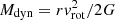 , is Mdyn = 7 − 9 × 10⁹ M⊙, corresponding to an escape velocity
  km s−1 at 1 kpc.
 |
Fig. 3. Cold molecular disc kinematics. Left panel: rotation velocity (green symbols) and velocity dispersion (blue symbols) as a function of the radius obtained from the best-fit disc dynamical model of the CO(2−1) data with 0.6 arcsec angular resolution. Middle and right panels: position–velocity diagrams along the kinematic major axis for the 0.2 arcsec and 0.6 arcsec resolution observations, respectively. The slit widths are set to the FWHM size of the synthetic beam major axis for each respective observation. Red contours and yellow circles represent the disc model, while blue contours represent the data. Contours are drawn at (1, 2, 4, 8, 16, 32, 64)σ. |
Parameters of the dynamical models of the multiphase disc.
3.3. Cold molecular wind
The largest residuals in Fig. 4 are detected as redshifted emission (v ∼ 80 km s−1) at the northwestern edge of the disc (EDGE1), and as blueshifted emission (v ∼ −80 km s−1) at the onset of the tail, at the southeastern edge of the disc (EDGE2-TAIL). In the latter position, the velocity dispersion map shows residual emission of about 40 km s−1 in amplitude. The CO and [O III] spectra extracted at EDGE1 and EDGE2-TAIL are shown in Fig. 5. Both show two bright components peaking at different velocities. At EDGE1 our disc best-fit dynamical model has a projected velocity of v(model)∼ − 185 km s−1 and σ(model)∼40 km s−1, which is consistent with the strongest CO component, which peaks at −180 km s−1. The additional emission components, spanning velocities of [−100, 0] km s−1 and [150, 300] km s−1, thus trace the off-planar motion of the gas, associated with a wind. The [O III] emission line at EDGE1 is offset by 100 km s−1 with respect to the CO disc component, suggesting that in this region the ionised gas does not partake in the disc rotation but instead traces perturbed kinematics, the result of a wind. Hα and Hβ emission lines show a similar line profile and velocity offset to [O III]. EDGE2-TAIL also shows a CO spectrum with two emission components. At this location, the best-fit dynamical model requires a velocity of ∼205 km s−1 and σ(model)∼40 km s−1, which is in between the two main CO peaks. Off-planar motions at EDGE1 (EDGE2-TAIL) are seen in the PV plot shown in Fig. 5 as regions with an offset of [−9, −5] arcsec ([4, 9] arcsec) and a line-of-sight velocity that is smaller than that of the disc. EDGE2-TAIL is further complicated by the tidal tail due to the interaction of NGC 2992 with NGC 2993 (Duc et al. 2000), and so it is hard to identify and separate tidal interaction from any wind. For this reason, we compute the wind parameters only at EDGE1 and do not include EDGE2-TAIL in the following analysis of the cold molecular wind. At EDGE1, we derive a cold molecular mass of  , and for EDGE2-TAIL we derive
  .
.
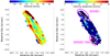 |
Fig. 4. Residual moment maps. Left panel: residual mean velocity map. Right panel: residual velocity dispersion map, where magenta circles mark the position of the cold molecular perturbations described in Sect. 3.3. Residual maps are obtained by subtracting the best-fit disc model maps from the observed ones. |
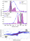 |
Fig. 5. EDGE1 and EDGE2 TAIL kinematics. Normalised CO(2−1) and [O III] spectra at the EDGE1 (upper panel) and EDGE2 TAIL (middle panel) regions. Purple histograms = CO(2−1) line. Blue symbols and solid line = [O III]. The dashed black line and grey shaded area represent the LOS velocity of the best-fit disc model and the [vmodel − σmodel, vmodel + σmodel] range, where (vmodel, σmodel) are (−185, 37) km s−1 and (206, 36) km s−1 at EDGE1 and EDGE2 TAIL, respectively. Bottom panel: CO(2−1) position–velocity plot (from 2017.1.01439.S) cut through EDGE1, EDGE2 TAIL, and the disc centre (along PA = 193 deg). The slit width is set to 0.6 arcsec (equal to the FWHM size of the synthetic beam major axis). Yellow symbols represent the disc model, while blue contours represent the data, with contours drawn at (2, 5, 10, 15, 30, 60)σ. |
In addition, we identify as cold molecular wind those regions that do not participate in the disc rotation as described by our best-fit model and are detected as molecular clumps located above and below the disc. The clump spectra are shown in Fig. 6 (right panel) and are coloured according to their peak velocity with respect to the rest frame, red for vpeak > 10 km s−1, green for −10 km s−1 < vpeak < 10 km s−1 and blue for vpeak < −10 km s−1. We note that the clumps on the western side of the disc are mainly redshifted, and those on the eastern side mainly blueshifted. We detect ten molecular clumps with > 3σ significance (Table 5). For each clump, we measure the wind velocity, vof, as the peak velocity, the line luminosity, the cold molecular mass, Mof, and the projected distance of each clump from the AGN, rof. We find a total cold molecular mass in the clumps of M(H2)clumps = 1.64 × 10⁷ (αCO/3.82) M⊙. The wind mass-outflow rate is computed at each radius rof by applying the relation from Fiore et al. (2017), assuming a spherical sector:
 (1)
(1)
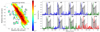 |
Fig. 6. Outflowing CO(2−1) clumps. Left panel: CO(2−1) intensity map with a cut at > 3σ. The labelled black polygons show the CO(2−1) clumps identified as cold molecular wind, i.e. not participating in the disc rotation. Right panel: blue, green, and red spectra are extracted from each molecular clump identified in the left panel, as labelled. Spectra are coloured according to the velocity shift of their peak: red with vpeak > 10 km s−1, green with −10 < vpeak < 10 km s−1, blue with vpeak < −10 km s−1. The grey-shaded histograms show the total CO(2−1) emission above a 3σ threshold extracted from the data-cube of coarser resolution. |
Properties of the cold molecular outflowing clumps.
A factor f = 3 is used with the assumption of a conical wind with constant density, as previously adopted (e.g. Vayner et al. 2017; Feruglio et al. 2017; Brusa et al. 2018). However, in other works (e.g. Bischetti et al. 2019a,b; Cicone et al. 2015; Veilleux et al. 2017; Marasco et al. 2020; Tozzi et al. 2021) the mass-outflow rate is rather computed with f equal to 1 by assuming a steady mass-conserving flow with constant velocity, in which the density at the outer radius is only one-third that of the average (see Veilleux et al. 2017, for a detailed discussion). The resulting values, assuming f = 3, relative to each component are reported in Col. (e) of Table 5.
3.4. Ionised gas distribution
We analysed the Hβ, [O III]λ5007 Å, Hα, and [N II]λ6583 Å emission lines extracted from the MUSE data-cube using the CUBEXTRACTOR package (Cantalupo et al. 2019). We used the procedure described below for each emission line following the approach described in Borisova et al. (2016), Cantalupo et al. (2019). First, we used the CubeSel tool to produce three z-direction cut data-cubes around the [O III] line and the Hβ line with a spectral window of 100 Å, while Hα and [N II] doublet lines are all included in a spectral window of 300 Å We removed any possible continuum emission for each spaxel within the MUSE FOV by applying a fast median-filtering approach using the CubeBKGSub task (Cantalupo et al. 2019). This tool allowed us to apply a median sigma clipping algorithm with a filter of 30 spectral layers (≈40 Å), carefully masking the emission lines. We then smoothed the spectrum with a median filter with radius equivalent to two bins in order to minimise the effect of line features in individual spectral regions. Finally, from each voxel in the cube, we subtracted the estimated continuum from the corresponding spaxel and spectral region. In this way, we obtained the continuum-subtracted cubes. In order to perform the following analysis, we produce a data-cube for each emission line of interest. For what concerns the Hα and [N II] doublet line complex, due to their blending, we modelled the emission lines by performing a pixel-by-pixel Gaussian fit with a minimum of one and a maximum of two components for each emission line. To produce the Hα cube, we subtracted the model [N II] doublet emission in each voxel, analogously, to obtain the [N II]λ6583 Å cube, we subtracted the previously modelled Hα and [N II]λ6548 Å profile. The Cube2Im task of the CUBEX tool produces 3D masks of the extended emission lines in each data-cube by applying a signal-to-noise ratio (S/N) threshold of 3 for Hα, of 2 for [O III], of 5 for Hβ and of 4 for [N II]. We applied different thresholds in order to optimise the S/N. Using only the voxels of the continuum-subtracted datacube defined in the 3D mask, the Cube2Im task allowed us to obtain the following three data products: (i) the surface brightness map, that is, an “optimally extracted narrow band image”, (ii) a map of the velocity distribution obtained as the first moment of the flux distribution, and (iii) a map of the gas velocity dispersion σgas, which was derived as the second moment of the flux distribution. All these data products shown in Fig. 7 were obtained by assuming rest wavelengths that are corrected according to the AGN redshift derived from CO(2−1) data and smoothed with a Gaussian-kernel of σ = 2 pixels.
 |
Fig. 7. Ionised gas moment maps. Moment maps of (top to bottom) Hα, [O III], Hβ, and [N II]λ6583 Å data-cubes. From left to right: integrated flux (moment-0), mean velocity (moment-1), and velocity dispersion maps (moment-2). The maps were obtained using the CUBEXTRACTOR package by Cantalupo et al. (2019) using a detection threshold that optimises the S/N (3σ threshold for Hα, 2σ threshold for [O III], 5σ for Hβ, and 4σ for [N II]). |
The intensity maps (Fig. 7) show a similar morphology in the four tracers. The emission peaks are consistent with the AGN position from ALMA. The emission is reduced along the cold molecular disc due to extinction by dust in the galaxy disc and dust lane (Trippe et al. 2008), mostly affecting the Hβ emission (Fig. 8). Two ionised cones emerge approximately perpendicular to the galactic disc in the northwest and southeast directions, with an opening angle of about 120 deg, which is consistent with the value estimated by García-Lorenzo et al. (2001). The edges of the ionisation cones are well defined in all tracers, as is the clumpy gas distribution within the cones. The mean velocity maps show a velocity gradient oriented from northeast to southwest and ranging from −300 to 300 km s−1, which likely traces the ionised disc. The kinematic major axis is consistent with that identified by CO(2−1). The disc velocity gradient is detected in all emission lines. Within the ionisation cones, the mean velocity maps show redshifted velocities exceeding 300 km s−1 in the northwestern cone, and enhanced blueshifted velocities in the southeastern cone, meaning that the west cone is mainly receding, while the eastern cone is mainly approaching, although different kinematic components are present along any line of sight. The σgas maps show the average velocity dispersion of the gas, which is limited by the MUSE resolution of about 70 km s−1 and therefore appears saturated around this value. Hα shows enhanced velocity dispersion values mainly at the center, where the Gaussian FWHM exceeds 300 km s−1. Here we expect residual contamination from the BLR (e.g. Guolo-Pereira et al. 2021). Hα shows σgas up to 250 km s−1 in the northwestern cone where the average velocity is mainly redshifted. [O III] shows large dispersion with σgas ∼ 250 km s−1 both at the nucleus and in the ionisation cones. Hβ shows enhanced σgas only at the AGN position.
 |
Fig. 8. Ionised gas properties. Left panel: HST image of NGC 2992 in the FQ606W filter (from the Mikulski Archive for Space Telescopes, Proposal 05479), showing the dust lane. Magenta contours are from the CO(2−1) intensity map (Fig. 2). Left-centre panel: Voronoi map of the total extinction in V band, AV. Right-centre panel: electron density map, ne, derived from the ionisation parameter (Sect. 3.4 and Appendix B). Right panel: mass surface density of the ionised gas. |
3.5. Ionised gas disc
We built a 3D tilted-ring model of the ionised gas disc by fitting the Hα data cube with 3DBAROLO, following the same approach adopted for CO(2−1), fixing the size of the annuli to 0.4 arcsec, and excluding the central region of 0.6 arcsec in radius that is dominated by the residual contamination from the BLR. Figure 9 shows the Hα rotation curve (90 km s−1 at the centre, increasing to 220 km s−1 at 1.5 kpc). The velocity dispersion decreases from ∼120 km s−1 near the nucleus down to ∼55 km s−1 at larger radii. The Hα rotation curve is globally consistent with the CO(2−1) one, but it extends further out to 1.8 kpc. We derived the dynamical mass as a function of the radius,  and found a total dynamical mass of ∼1010 M⊙ enclosed in a 1.5 kpc region. Figure 9 (right panel) shows the position–velocity diagram along the kinematic major axis (PA = 210 deg). The disc model well describes the data at projected radii of > 4 arcsec, while the nuclear region shows gas with very highly redshifted and blueshifted velocities of up to 500 km s−1 and down to −750 km s−1. This is not due to the BLR as the latter is unresolved, but rather traces the ionised wind. The same pattern is also seen in the PV diagram taken for the [O III]λ5007 Å emission line (Fig. 10).
 |
Fig. 9. 3DBAROLO dynamical model of the ionised gas disc obtained by fitting the Hα data cube. Left panel: rotation curve (green symbols) and velocity dispersion (blue symbols) corrected for beam smearing, as a function of the radius obtained from the best-fit disc model. Right panel: position–velocity diagram along the kinematic major axis, PA = 210 deg. Red contours and yellow filled circles represent the disc model, blue contours represent the data. Contours are drawn at (1, 2, 4, 8, 16, 32, 64)σ. |
 |
Fig. 10. Ionised gas kinematics traced with the [O III] emission line. Left panel: position–velocity diagram of the [O III] emission along the kinematic major axis, PA = 210 deg. Central panel: [O III] intensity map (grey scale), red and blue contours show the high-velocity [O III] emission between [200, 1000] and [−1000, −200] km s−1, respectively. Right panel: map of the W80 of the [O III] line. |
3.6. Ionised gas densities and masses
To assess the ionised gas contribution to the global baryon budget, we calculate the gas mass in the warm ionised phase from the luminosity of [O III], assuming recombination in a fully ionised medium with a gas temperature of 104 K and using the following equation (Carniani et al. 2015; Bischetti et al. 2017):
![Mathematical equation: $$ \begin{aligned} M_{\rm [O\,III]} = 0.8 \times 10^8\,M_{\odot } \bigg (\frac{C}{10^{\mathrm{[O/H]}{-}\mathrm{[O/H]}_{\odot }}}\bigg ) \bigg (\frac{L_{\rm [O\,III]}}{10^{44}}\bigg ) \bigg (\frac{n_{\rm e}}{500}\bigg )^{-1}, \end{aligned} $$](/articles/aa/full_html/2023/11/aa45729-22/aa45729-22-eq10.gif) (2)
(2)
where [O/H] is the metallicity, ne is the electron density in units of cm−3, and L[O III] is the [O III] luminosity in erg s−1. We correct L[O III] for dust extinction, because the dust lane seen in the HST image (Fig. 8, left panel) is expected to produce significant attenuation along the disc (Trippe et al. 2008). We calculate the extinction map in V band, AV, through the Balmer decrement Hα/Hβ, assuming a Calzetti et al. (2000) attenuation law.
We apply a Voronoi tessellation (Cappellari & Copin 2003) based on Hβ – the faintest optical line – to derive both the extinction and the ionisation parameter (see below), requiring a S/N ≥10 per wavelength channel in each cell2. To account for the outer regions, where Hβ is undetected but [O III] is detected, we calculate upper limits for the Hβ flux. In the following, we derive all parameters in Eq. (2) using this Voronoi tassellation, except for the metallicity, which is assumed to be constant and equal to the solar value.
The highest values of AV are found at the dust lane and inclined disc, while the ionisation cones show modest reddening, on average AV < 1 (Fig. 8, left-central panel). We calculate the electron density (Fig. 8, central-right panel) using the relation by Baron & Netzer (2019):
 (3)
(3)
where Lbol is the bolometric luminosity (1044.13 erg s−1) and U is the ionisation parameter derived using the [O III]/Hβ and [N II]/Hα line ratios, see Appendix B. The typical uncertainty associated with ne is 0.6 dex (Baron & Netzer 2019). The highest ne ∼ 103 − 104 cm−3 is found in the nuclear region. Further out across the disc ne is 100 − 1000 cm−3, while it is ∼10 − 100 cm−3 in the ionisation cones. By applying Eq. (2), we derive the mass surface density of ionised gas (Fig. 10, right panel). We derive a total ionised gas mass of Mgas, ion = (4.5 ± 0.3)×107 M⊙, of which Mgas, ion = (1.27 ± 0.03)×107 M⊙ (or 27% of the total) is in the host galaxy disc, while the remaining fraction is located off the galactic plane, mainly in the ionisation cones.
3.7. Ionised wind
In Sect. 3.5, we show that, in addition to disc rotation and BLR, Hα kinematics traces a wide opening-angle ionised wind. Here we examine the [O III] emission. This is not contaminated by BLR and therefore best traces the ionised wind. The [O III] PV plot (Fig. 10) shows that the ionised gas disc is also detected in [O III]. The [O III] wind is detected in the nuclear region, where its (projected) velocity exceeds v[O III] = |1000| km s−1, and in the ionisation cones, where v[O III] gradually decreases with increasing distance from the nucleus. A representation of the [O III] kinematics within the ionisation cones is given in the middle panel of Fig. 10, where we plot red and blue contours, tracing the integrated [O III] emission in the velocity ranges of [200, 1000] km s−1 and [−1000, −200] km s−1, respectively. These contours highlight ionised gas moving at high velocities within the cones, both approaching and receding. In several positions, the gas has both an approaching and receding component, likely tracing the walls of the wind cone filled by clumpy gas along the line of sight (Veilleux et al. 2001; Friedrich et al. 2010; Mingozzi et al. 2019; Guolo-Pereira et al. 2021). The right panel of Fig. 10 shows the [O III] W80 map3 – a proxy of the gas turbulence – derived using the Voronoi tessellation (see Sect. 3.6). The ionised gas distribution shows regions of enhanced W80, reaching up to 500 km s−1 both at the nucleus and in the cones out to kiloparsec distances from the centre, highlighting the presence of broad components due to the outflowing gas.
4. Discussion
4.1. The multiphase disc
The cold molecular and ionised gas discs are of approximately the same size, namely 1.5 and 1.8 kpc (radius), respectively. In CO(2−1), we resolve a disc and an inner CNR, the latter with an inner radius of 65 pc. The rotation velocity of the cold molecular disc is vrot, mol = 260 ± 10 km s−1, while that of the ionised disc is vrot = 216 ± 35 km s−1, suggesting that the cold molecular and ionised discs are co-spatial and trace the same kinematics. The velocity dispersion of the cold molecular gas within the disc (from the highest resolution data) is 16 ± 10 km s−1, which agrees with the average value found for local star forming galaxies (Übler et al. 2019, and references therein). For the ionised component, we find σgas = 55 ± 35 km s−1, which is affected by the limited spectral resolution of MUSE (∼70 km s−1) and therefore cannot be compared with the average value in local star forming galaxies (20 km s−1, e.g. Epinat et al. 2010). Conversely, in the CNR, we find that σgas is enhanced with respect to local star-forming galaxies (Übler et al. 2019), σgas = 38 ± 12 km s−1 for the cold molecular and 117 ± 36 km s−1 for the ionised phases, respectively. These velocity dispersions are a factor of 3−4 larger than those found in the discs of star forming galaxies (Übler et al. 2019). The [O III] line –which is associated with the ionised component– in this location is broadened by the effect of the ionised wind. We therefore conclude that we find enhanced σgas only in the central kiloparsec of NGC 2992, where the wind interacts with the ISM, but find no enhanced σgas on larger scales across the host galaxy disc (Figs. 3 and 9). The dynamical ratio for the cold molecular component is vrot/σgas = 10 at 1 kpc radii, which is consistent with a rotationally supported disc. At EDGE1 and EDGE2-TAIL, we measure vrot/σgas ∼ 5.4. For the cold molecular phase, we do not find dynamical ratios of smaller than unity, which are observed in mergers (Cappellari 2017). However, we do find dynamical ratios of less than unity in the ionised gas phase, which at the nucleus shows vrot/σgas ∼ 0.8, likely owing to the effect of the fast ionised wind detected in this region.
4.2. The multiphase wind
The projected velocity of the ionised wind reaches its maximum (v98 about −900 km s−1) close to the nucleus, at the apex of the eastern cone, where the [O III] profile shows a prominent asymmetric blueshifted wing exceeding −1000 km s−1 (Fig. 11). At this side of the galaxy, the sightline reaches the nucleus and the BLR, which is seen through broad Hα emission (Veilleux et al. 2001; Guolo-Pereira et al. 2021). v98 decreases further out in the ionisation cones, reaching a few hundred km s−1 (Fig. 11). The latter values of projected velocity in the outer ionisation cones are in agreement with those reported for Hα and near-IR emission lines (Veilleux et al. 2001; Guolo-Pereira et al. 2021; Friedrich et al. 2010), we note that, on the other hand, these latter authors did not detect the very fast [O III] component with velocity of −1000 km s−1. Owing to the wide opening angle of the cones and the projection effects (the orientation of the cones is mainly on the plane of the sky), these [O III] velocity estimates represent a lower limit.
 |
Fig. 11. Ionised gas disc and wind kinematics. Top panel: simplified model of the source based on the ionised gas kinematics. Magenta = nucleus (N), purple = inner disc, Light/dark green: outer disc, red/burgundy = west ionisation cone (W1/W2), blue/cyan = east ionisation cone (E1/E2). Bottom panel: normalised [O III] line profiles at the wind regions, spectra are coloured according to the model map in the left panel. |
In order to derive the ionised wind mass and mass-loss rate, we built a simplified source model, where we identified regions with similar kinematic properties, and analysed them individually. As the NGC 2992 disc is viewed close to edge-on and the ionisation cones are close to the plane of the sky, we can separate disc and wind relatively easily. In the source model (Fig. 11), we considered a disc inclination of 80 deg based on the best-fit dynamical model, and an aperture of 120 deg for the cones. We identified eight regions, namely the nucleus (including the BLR), the galactic disc, which in turn has a high density portion around the nucleus at r < 1 kpc, and two lower ne portions further out on the north and south sides (green regions in Fig. 11). Each ionisation cone is further divided into two subregions, the inner and the outer cones, whose boundary is set at r = 1.5 kpc (Fig. 8). The [O III] line at the nucleus (N, magenta region) is characterised by a very broad, asymmetric profile with a blueshifted wing exceeding −1000 km s−1 from the rest frame (v984 = −895 ± 5 km s−1, Table 6), this traces the nuclear ionised wind. The disc inclination of 80 deg allows a line of sight to the nucleus, whereas the rear part of the nuclear wind is obscured by the dusty disc. In the east cone, the [O III] profile is mainly blueshifted, decreasing from v98 ∼ −375 km s−1 (E1) to v98 ∼ −227 km s−1 (E2). While in the west cone, according to the [O III] velocity map of Fig. 7, the [O III] profile is mainly redshifted with v98 = 217 ± 5 km s−1 (W1, W2). We used Eq. (2) to derive the mass in the ionised wind. The extinction is assumed negligible in the outer part of the ionisation cones, where no dust lane is detected (see left panel of Fig. 8). We calculated the mass-outflow rate in each region using Eq. (1), where the wind radius is the outer radius of each region and the wind velocity is the maximum in absolute value between v025 and v98. The wind velocity derived as described above is a lower limit owing to the low inclination of the ionisation cones. Table 6 summarizes the [O III] wind parameters. We derived a total ionised wind mass of Mof, ion = (3.2 ± 0.3)×107 M⊙, and a total ionised outflow rate of Ṁof,ion = (13.5 ± 1) M⊙ yr−1. Using Hβ and the same procedure, we found an ionised gas mass of 6.4 × 10⁷ M⊙, which is a factor of two larger than the mass estimated from [O III], and is in agreement with previous results (Liu et al. 2013a; Harrison et al. 2014; Carniani et al. 2015). This indicates that the wind mass based on [O III] is a robust lower limit.
Properties of the ionised gas wind derived from [O III] emission.
The total ionised wind mass is larger than the estimate reported by Veilleux et al. (2001). This discrepancy is likely due to the assumption of uniform electron density (100 cm−3) in Veilleux et al. (2001), and to the fact that these latter authors did not consider the very fast nuclear wind component. Most studies assume a constant ne (e.g. Veilleux et al. 2001; Liu et al. 2013b; Husemann et al. 2016; Tozzi et al. 2021), or use the ratio of [S II] emission lines to derive the electron density (e.g. Nesvadba et al. 2006, 2008; Mingozzi et al. 2019; Marasco et al. 2020; Kakkad et al. 2022). Typical [S II]-based estimates are in the range of 200−1000 cm−3, but this method underestimates the true densities by one to two orders of magnitude (Baron & Netzer 2019; Revalski et al. 2022). Moreover, the combination of [O III] or Hα line luminosity with [S II]-based electron density may result in inconsistent gas mass estimates, because [O III] and Hα emission lines are emitted throughout most of the ionised cloud, while the [S II] lines are primarily emitted close to the ionisation front in the cloud. Therefore, the [O III] and Hα lines trace regions of higher electron density compared to [S II]. Based on the Baron & Netzer (2019) prescription, we derived a spatially resolved ne, which spans a broader density range, 100–104 cm−3 (Fig. 8), compared to that found by Mingozzi et al. (2019), Kakkad et al. (2022). Based on these ne and the [O III] kinematics, we derived ionised outflow rates at three characteristic radii: 300 pc, 1.5 kpc, and ∼6 kpc (Table 6). At a radius of 300 pc, we find an outflow rate of Ṁof = 3.6 ± 0.5 M⊙ yr−1, which at face value is consistent with the one derived by Guolo-Pereira et al. (2021) based on Hα. However, both our estimates of electron density and wind velocity are an order of magnitude and a factor of five larger, respectively, than in Guolo-Pereira et al. (2021), suggesting a faster and tenuous wind in the nuclear region; this cannot be probed by Hα due to BLR contamination. If we examine the large-scale ionised wind through the cones, the [O III] wind velocity is consistent with that reported by Veilleux et al. (2001) for Hα. For an electron density of 40 cm−3, the [O III] outflow rate of 3.6 ± 0.5 M⊙ yr−1 (Table 6) is in agreement with that derived by Veilleux et al. (2001). The ionised wind is certainly AGN-driven, as demonstrated by multiple authors (e.g. Veilleux et al. 2001; Friedrich et al. 2010), and is multiphase on kiloparsec scales, as both the ionised and the cold molecular phases participate in the wind.
Near the northern cone wall, we detected a region with high velocity dispersion in CO that shows a wind component (EDGE1, Fig. 5). At this location, both CO and [O III] trace a multiphase wind with approximately the same velocity (about −50 km s−1), and a cold molecular mass of 2.7 × 10⁷ M⊙, with [O III] showing a larger σgas than CO. A similar configuration is found in the southern cone (EDGE2-TAIL), but here the kinematics is complicated by a tidal tail connecting to NGC 2993.
Ten cold molecular outflowing clumps are detected below the disc (in the eastern side) out to projected distances of ∼0.8 kpc (Table 5), and above the disc (western side, Fig. 6). We did not detect cold molecular gas at projected distances of greater than ∼1 kpc from the disc. The velocity of the cold molecular clumps is of the order of tens of km s−1, reaching a maximum of −200 km s−1 (clump C2). Their Full Width at Zero Intensity (FWZI) appears very narrow for some clumps (40 km s−1), while for other clumps FWZI is in the range of 144−288 km s−1, with an average FWZI of 110 km s−1. This suggests that this is disc material that has been entrained in the ionised wind and lifted up. For this reason, for the cold molecular wind we adopted the same conversion factor as for the disc, obtaining a cold molecular wind mass of Mof, mol = 4.3 × 10⁷ M⊙; that is, about twice as massive as the ionised mass on the same scale (1.5 kpc radius, see Table 6). Should the conversion factor be lower, as in the case of optically thin outflows (Morganti et al. 2015; Dasyra et al. 2016), αCO = 0.3 M⊙(K km s−1 pc2)−1. This would translate into a ten times smaller cold molecular gas mass in outflow, with Mof, mol = 0.13 × 10⁷ M⊙ in the clumps, and Mof, mol = 0.21 × 10⁷ M⊙ in EDGE1, with a total cold molecular gas mass of Mof, mol = 0.34 × 10⁷ M⊙.
In the inner part of the cones (W1 and E1), the ionised wind is faster (vof ∼ −220 km s−1 and 375 km s−1) than the cold molecular wind, which spans a slower velocity range on these scales (1−1.5 kpc radius, Table 5). Therefore, at the kpc scale, the multiphase wind has a fast ionised component, and a slower cold molecular component that carries the bulk of the mass. On larger scales, the wind is only in the ionised phase. Comparing the results of this work with the correlation between the mass-outflow rate and the AGN bolometric found by Fiore et al. (2017), we note that the ionised and X-ray winds are broadly consistent with the correlations, whereas the cold molecular outflow rate is significantly below the best-fit correlation for cold molecular winds. This result is consistent with other cold molecular outflows in nearby objects (e.g. Feruglio et al. 2020; Zanchettin et al. 2021; Ramos Almeida et al. 2022; Lamperti et al. 2022). The correlation found by Fiore et al. (2017) could be biased towards positive outflow detections and therefore to high values of outflow rate, because it was derived for a sample of high luminous objects. This highlights the importance of performing statistical studies on unbiased AGN samples to derive scaling relations.
By comparing the energetics of the UFO and the nuclear portion of the [O III] wind, we find that the momentum boost Ṗof/Ṗrad6 is of the order 10−2, which is smaller than what is expected for a radiatively driven momentum-conserving wind. The [O III] wind that we observe on scales of 300 pc may be related to a previous UFO episode given the different timescales implied by the UFO and [O III] wind kinematics.
4.3. Radio bubbles and their interplay with the ISM
The figure-eight-shaped radio feature with limb-brightened prominent loops has been interpreted as two expanding gas bubbles. Chapman et al. (2000) suggested that a compact radio outflow may power the bubbles and produce the nuclear outflow seen in the near-IR. The radio outflow is unresolved in our VLA data and should be confined within 150 pc from the AGN. The power of the radio outflow would be Pof, radio ≈ 5.8 × 1043(Pradio/1040)0.70 erg s−1 = 6 × 1042 erg s−1 using the power in the radio bubbles and the empirical relation by Cavagnolo et al. (2010) derived at 1.4 GHz7. However, this approach has large uncertainties and may be considered a lower limit to the outflow power (Morganti 2021; Mukherjee et al. 2018); nevertheless, such an outflow would be able to power the ionised wind seen on subkiloparsec scales.
The radio bubbles are neither parallel nor perpendicular to the disc, but probably have an intermediate PA, meaning that they are misaligned with respect to the ionisation cones seen in optical lines. For this reason, it is unlikely that the ionised gas wind on large scales is directly related to the radio bubble and outflow (Veilleux et al. 2001), but is rather associated with previous AGN episodes. We find that the bubbles are spatially related to interesting ISM features (Fig. 12). The outflowing cold molecular clumps are located at the edges of the southern bubble, and the 1.3 mm continuum emission from cold dust is detected outside the disc plane and coincident with the position of the southern bubble at its southern rim. For the northern bubble, the association with cold dust is less clear. This spatial overlap suggests that both cold gas and dust have been uplifted by the bubble. At the rim of the southern bubble, there is an arch of ionised gas (seen in Hα) with redshifted velocity (see also Guolo-Pereira et al. 2021) that is spatially coincident with dust emission. The rightmost panel of Fig. 12 shows that both bubbles overlap with regions where the ionised gas has a large line width (W80). These pieces of evidence indicate that the bubbles interact with the surrounding ISM, including all gas phases and dust, and are physically related to the multiphase wind on subkiloparsec scale. As proposed by Xu & Wang (2022), it is possible that the hot gas probed by soft X-ray emission at the bubble location is heated by wind shocks (Zakamska & Greene 2014; Giroletti et al. 2017; Zubovas & Nayakshin 2014; Nims et al. 2015). In order to verify whether there is evidence of shocks, we investigated the forbidden [O I]λ6003 Å line, which is included in the MUSE data and may be used to trace the shock-heated ISM. High [O I]/Hα ratios (log[O I]λ6003 Å/Hα > −1.6) are expected where shocks are present (Monreal-Ibero et al. 2010; Rich et al. 2011, 2014, 2015). Veilleux & Osterbrock (1987) suggest that shock heating should be considered as an alternative ionisation mechanism in low-ionization nuclear emission-line gegions (LINERs). Monreal-Ibero et al. (2006, 2010) also support the idea that a relative increase in the velocity dispersion and shift of the strong emission line ratios in the diagnostic BPT-like diagram towards the LINERs region is indicative of gas excited by slow shocks. We computed the [O I]/Hα ratio for NGC 2992 (see Appendix C and the right panel of Fig. C.1), finding a ratio in the range of −1.7 < log[O I]λ6003 Å/Hα < −0.8, which is consistent with values reported for luminous infrared galaxies (LIRGs) and ultraluminous infrared galaxies (ULIRGs; Veilleux & Osterbrock 1987; Monreal-Ibero et al. 2006, 2010; Rich et al. 2011, 2014, 2015). Inside the radio bubble, we find log[O I]/Hα ∼ −1.1, whereas towards the edge of the radio bubble, the value is about log[O I]/Hα ∼ −1.4. These values are consistent with shock regions, and, together with the evidence of increased gas velocity dispersion within the radio bubble (Fig. 12), support the scenario in which the hot gas in the bubble may be heated by wind shocks. The shocks could be provided either by the fast [O III] wind (Zakamska & Greene 2014), which close to the nucleus exceeds −1000 km s−1, or by the UFO, which has kinetic power in the range of 7 × 1042 − 1.1 × 1044 erg s−1, depending on the state of the highly variable AGN (Marinucci et al. 2018), or both.
 |
Fig. 12. Interplay of the radio bubbles with the multiphase ISM. From left to right: CO(2−1) mean intensity map (same as Fig. 2, bottom-left panel), ALMA 1.3 mm continuum (same as Fig. 1, right panel), Hα moment 1 map (same as Fig. 7, top-central panel), and [O III] W80 map (same as Fig. 10, right panel). Black contours are from the EVLA radio continuum map at 6 cm (Fig. 1, left panel), drawn at (1, 5, 10)σ. |
4.4. The star-formation law across the disc
We computed the spatially resolved ratio between the cold molecular and ionised gas mass surface densities, Σgas, mol/Σgas, ion (Fig. 13). The disc is dominated by a clumpy cold molecular distribution, while at EDGE1 and EDGE2-TAIL the cold molecular to ionised mass ratio decreases. From the 6 cm radio emission detected within the inclined disc, and by applying the radio–far-IR correlation (Shao et al. 2018), we derived SFR = 0.4 M⊙ yr−1, where we considered only the radio emission located at the disc, and excluded the AGN and the radio bubble emission. This SFR is smaller than the value obtained from far-IR spectral energy distribution (SED) decomposition (SFR = 3.6 ± 0.3 M⊙ yr−1, Gruppioni et al. 2016). Assuming that 6 cm emission arises from the same region where cold dust is detected through the 1.3 mm continuum (Fig. 1), and scaling from the 1.3 mm flux, we obtain SFR = 1.13 M⊙ yr−1, which is still a factor of three smaller than the Gruppioni et al. (2016) value. These discrepancies could be related to the sensitivity limit of the 6 cm observations, which probe a smaller region of the disc compared to both far-IR Herschel (Gruppioni et al. 2016) and ALMA observations. Based on the 6 cm radio continuum and the CO(2−1) emission, we derived ΣSFR = 0.4 and 0.5 M⊙ yr−1 kpc−2 and ΣH2 = 168 and 175 M⊙ pc−2 (corrected for the disc inclination, i = 80 deg) for the two sides of the disc, respectively, and we used them to study the spatially resolved cold molecular star-formation law on scales of 200 pc. Figure 13 shows the star-formation law on scales of 200 pc for NGC 2992 and a compilation of local AGN host galaxies from Casasola et al. (2015). We find that NGC 2992 is consistent with the correlation found for local AGN hosts.
 |
Fig. 13. Star formation across the disc of NGC 2992. Upper panel: map of the cold molecular to ionised ([O III]) gas surface densities ratio. The CO map has been degraded to the same angular resolution of the [O III] map. Black contours are from the residual velocity dispersion map (right panel Fig. 4) and are drawn at (5, 10, 20, 40) km s−1. Bottom panel: spatially resolved star-formation law on scales of ∼200 pc. Purple symbols are the two sides of the disc where radio continuum is detected (this work). Black symbols are data derived for local AGN host galaxies, along with their best-fit relation (dashed line) and dispersion (shaded area) from Casasola et al. (2015). |
4.5. The cold dust
ALMA continuum data show a dust reservoir co-spatial with the galaxy cold molecular disc in a region that is 1.8 kpc2 wide. Mid-IR extended emission at 11.2 μm, which is likely produced by dust heated by star formation, was detected on approximately the same scales (García-Bernete et al. 2015). Assuming a grey body model with a dust temperature of Tdust = 30 K and β = 1.5 (e.g. Skibba et al. 2011), we derived a cold dust mass of Mdust = (4.04 ± 0.03)×106 M⊙, which is consistent with the value obtained from Herschel unresolved data (García-Bernete et al. 2015). We therefore derived a gas-to-dust ratio of GDR ∼ 80 across this region, which is broadly consistent with the value for the Milky Way (Bohlin et al. 1978) and with those for nearby galaxies with similar metallicity (Rémy-Ruyer et al. 2014; Galliano et al. 2018; De Vis et al. 2017, 2019). We argue that this dust reservoir is responsible for the extended Fe Kα emission seen on 200 pc scales around the nucleus in hard X-rays and interpreted as reflection by cold dust by Xu & Wang (2022). This seems a common feature of Compton-thick AGN (e.g. Feruglio et al. 2020), and can also be probed in Compton-thin AGN if they are in a low state, as is the case for NGC 2992 (Xu & Wang 2022). Malizia et al. (2020) argued that NGC 2992 is an example of a Seyfert 1 disguised as a Seyfert 2 because of galactic obscuration from material located in the host galaxy on scales of hundreds of parsecs and not aligned with the putative absorbing torus of the AGN, which contributes significantly to the AGN obscuration.
Based on our M(H2), we estimated a line-of-sight H2 column density of N(H2)≈1.14 × 1022 cm−2 towards the dusty disc, which is broadly consistent with the NH derived in optical and X-rays (Yaqoob et al. 2007; Malizia et al. 2012), and in the range reported by Malizia et al. (2020) for misclassified type 1 AGN. In NGC 2992, the modest absorption is likely related to the dust on the host galaxy rather than to the dusty torus. This is in good agreement with the small torus radius of about 1.4 pc derived for NGC 2992 by García-Bernete et al. (2015), which is typical of Seyfert 1 galaxies.
5. Conclusions
We present an analysis of the multiphase gas in the disc and wind of NGC 2992 based on ALMA, VLA, and VLT/MUSE data. We find that CO(2−1) and Hα emission lines trace an inclined (i = 80 deg) multiphase disc with radii of 1.5 and 1.8 kpc, respectively. The rotation curves of the cold molecular and ionised phases are consistent with vrot, mol = 260 ± 10 km s−1 and vrot, ion = 216 ± 35 km s−1, and therefore the cold molecular and ionised discs are co-spatial and trace the same kinematics. The velocity dispersion of the cold molecular phase, σgas, is consistent with that of star forming galaxies at the same redshift (Übler et al. 2019), with the exception of some peculiar regions where the wind interacts with the host galaxy disc.
We find a fast, clumpy ionised wind traced by [O III] within a biconical configuration with a wide opening angle, extending from the nucleus out to 7 kpc with a velocity exceeding 1000 km s−1 in the central 600 pc region. Within the inner 600 pc region, and in the region between the ionised cone walls and the disc, the velocity dispersion σgas is increased by a factor of 3−4 for both the cold molecular and the warm ionised phase with respect to that found in star forming galaxies, suggesting that a disc–wind interaction locally boosts the gas turbulence. In the ionisation cones on large scales, the wind velocity is of the order of 200 km s−1, which is in agreement with previous findings (Veilleux et al. 2001; Friedrich et al. 2010), but a large range of wind velocities is detected over different positions within the cones, owing to line-of-sight effects. The electron density in the cones, ne, spans a range of 100–104 cm−3, and implies a total ionised wind mass of Mof, ion = 3.2 × 10⁷ M⊙, and a total ionised outflow rate of Ṁof,ion = 13.5 ± 1 M⊙ yr−1.
On kiloparsec scales, we also detected a slower, clumpy cold molecular wind with a velocity v98 of up to 200 km s−1, which carries a mass of Mof, mol = 4.3 × 10⁷ M⊙, which is about twice the ionised wind mass on the same physical scales. On scales above few kiloparsecs, the wind is detected in only the ionised phase across the ionisation cones.
In the central kiloparsec, the multiphase wind is associated with the radio bubbles, as the cold molecular outflowing clumps and turbulent outflowing ionised gas are detected across the radio bubbles and at their limbs. As proposed by Xu & Wang (2022), it is possible that the hot gas probed by soft X-ray emission filling the radio bubbles in NGC 2992 is heated by wind shocks, which could be produced either by the fast [O III] wind or by the UFO, or both (Zakamska & Greene 2014). The [O I]/Hα ratio and the gas velocity dispersion support the presence of shocks in and around the radio bubbles. The overall picture suggests a shocked wind heating the gas on scales up to 700 pc from the AGN, which in turn emits the soft X-rays forming the hot bubble. The ionised wind entrains the cold molecular gas and dust from the disc and lifts it up to a distance of ∼1 kpc. A compact radio outflow extending over < 150 pc, which is unresolved in current data, could also be the origin of the radio bubbles and of the multiphase wind. Higher-resolution VLA data could shed light on the presence of a nuclear radio jet and its power.
We detected a cold dust reservoir co-spatial with the cold molecular disc, with a dust mass of Mdust = (4.04 ± 0.03)×106 M⊙ and a gas-to-dust ratio ≈80. We propose that this dust reservoir is responsible for the extended Fe Kα emission seen on 200 pc scales around the nucleus in hard X-rays and interpreted as reflection by cold dust.
The noise is computed as the rms extracted from the Hβ cube masking the line emission. An initial smoothed 3D mask is applied, which we obtained by including the voxels with emission above 1 rms for at least three connected spectral channels.
W80 = v90 − v10 represents the width of the line that contains 80% of the wind flux, calculated as the difference between the 90th and 10th percentiles velocities.
v98 is defined as the wind velocity enclosing the 98% of the cumulative velocity distribution of the outflowing gas.
v02 is defined as the wind velocity enclosing 2% of the cumulative velocity distribution of the outflowing gas, analogous to v98 but on the blueshifted side of the line profile.
The wind momentum boost is the ratio between the outflow momentum flux, Ṗof = Ṁof · v98, and the radiative momentum flux, Ṗrad = Lbol/c.
The 5 GHz radio power is consistent with the measurements at 1.4 and 8.4 GHz (Meléndez et al. 2010).
Acknowledgments
We thank the anonymous referee for their insightful report that helped us improving the paper. We thank A. Marconi and G. Venturi for helping in data analysis. This paper makes use of the ALMA data from projects: ADS/JAO.ALMA#2017.1.01439.S and 2017.1.00236.S. ALMA is a partnership of ESO (representing its member states), NSF (USA) and NINS (Japan), together with NRC (Canada), MOST and ASIAA (Taiwan), and KASI (Republic of Korea), in cooperation with the Republic of Chile. The Joint ALMA Observatory is operated by ESO, AUI/NRAO and NAOJ. The National Radio Astronomy Observatory is a facility of the National Science Foundation operated under cooperative agreement by Associated Universities, Inc. Based on observations collected at the European Southern Observatory under ESO program 094.B-0321. This research made use of observations made with the NASA/ESA Hubble Space Telescope, and obtained from the Hubble Legacy Archive, which is a collaboration between the Space Telescope Science Institute (STScI/NASA), the Space Telescope European Coordinating Facility (ST-ECF/ESAC/ESA) and the Canadian Astronomy Data Centre (CADC/NRC/CSA). We acknowledge financial support from PRIN MIUR contract 2017PH3WAT, and PRIN MAIN STREAM INAF “Black hole winds and the baryon cycle”. Sebastiano Cantalupo and Andrea Travascio gratefully acknowledge support from the European Research Council (ERC) under the European Union’s Horizon 2020 research and innovation program grant agreement No. 86436.
References
- Accurso, G., Saintonge, A., Catinella, B., et al. 2017, MNRAS, 470, 4750 [NASA ADS] [Google Scholar]
- Alonso-Herrero, A., Pereira-Santaella, M., García-Burillo, S., et al. 2018, ApJ, 859, 144 [Google Scholar]
- Alonso-Herrero, A., García-Burillo, S., Pereira-Santaella, M., et al. 2019, A&A, 628, A65 [NASA ADS] [CrossRef] [EDP Sciences] [Google Scholar]
- Argyle, R. W., & Eldridge, P. 1990, MNRAS, 243, 504 [NASA ADS] [Google Scholar]
- Asmus, D. 2019, MNRAS, 489, 2177 [NASA ADS] [CrossRef] [Google Scholar]
- Baron, D., & Netzer, H. 2019, MNRAS, 486, 4290 [Google Scholar]
- Bischetti, M., Piconcelli, E., Vietri, G., et al. 2017, A&A, 598, A122 [NASA ADS] [CrossRef] [EDP Sciences] [Google Scholar]
- Bischetti, M., Piconcelli, E., Feruglio, C., et al. 2019a, A&A, 628, A118 [NASA ADS] [CrossRef] [EDP Sciences] [Google Scholar]
- Bischetti, M., Maiolino, R., Carniani, S., et al. 2019b, A&A, 630, A59 [NASA ADS] [CrossRef] [EDP Sciences] [Google Scholar]
- Bohlin, R. C., Savage, B. D., & Drake, J. F. 1978, ApJ, 224, 132 [Google Scholar]
- Borisova, E., Cantalupo, S., Lilly, S. J., et al. 2016, ApJ, 831, 39 [Google Scholar]
- Brinks, E., Duc, P. A., Springel, V., et al. 2000, in Mapping the Hidden Universe: The Universe behind the Mily Way – The Universe in HI, eds. R. C. Kraan-Korteweg, P. A. Henning, & H. Andernach, ASP Conf. Ser., 218, 341 [Google Scholar]
- Brusa, M., Cresci, G., Daddi, E., et al. 2018, A&A, 612, A29 [NASA ADS] [CrossRef] [EDP Sciences] [Google Scholar]
- Calzetti, D., Armus, L., Bohlin, R. C., et al. 2000, ApJ, 533, 682 [NASA ADS] [CrossRef] [Google Scholar]
- Cantalupo, S., Pezzulli, G., Lilly, S. J., et al. 2019, MNRAS, 483, 5188 [Google Scholar]
- Cappellari, M. 2017, MNRAS, 466, 798 [Google Scholar]
- Cappellari, M., & Copin, Y. 2003, MNRAS, 342, 345 [Google Scholar]
- Cappellari, M., & Emsellem, E. 2004, PASP, 116, 138 [Google Scholar]
- Carniani, S., Marconi, A., Maiolino, R., et al. 2015, A&A, 580, A102 [NASA ADS] [CrossRef] [EDP Sciences] [Google Scholar]
- Casasola, V., Hunt, L., Combes, F., & García-Burillo, S. 2015, A&A, 577, A135 [NASA ADS] [CrossRef] [EDP Sciences] [Google Scholar]
- Cavagnolo, K. W., McNamara, B. R., Nulsen, P. E. J., et al. 2010, ApJ, 720, 1066 [Google Scholar]
- Chapman, S. C., Morris, S. L., Alonso-Herrero, A., & Falcke, H. 2000, MNRAS, 314, 263 [NASA ADS] [CrossRef] [Google Scholar]
- Cicone, C., Maiolino, R., Gallerani, S., et al. 2015, A&A, 574, A14 [NASA ADS] [CrossRef] [EDP Sciences] [Google Scholar]
- Colbert, E. J. M., Strickland, D. K., Veilleux, S., & Weaver, K. A. 2005, ApJ, 628, 113 [Google Scholar]
- Colina, L., Fricke, K. J., Kollatschny, W., & Perryman, M. A. C. 1987, A&A, 178, 51 [NASA ADS] [Google Scholar]
- Cresci, G., Marconi, A., Zibetti, S., et al. 2015, A&A, 582, A63 [NASA ADS] [CrossRef] [EDP Sciences] [Google Scholar]
- Dasyra, K. M., Combes, F., Oosterloo, T., et al. 2016, A&A, 595, L7 [NASA ADS] [CrossRef] [EDP Sciences] [Google Scholar]
- De Vis, P., Gomez, H. L., Schofield, S. P., et al. 2017, MNRAS, 471, 1743 [Google Scholar]
- De Vis, P., Jones, A., Viaene, S., et al. 2019, A&A, 623, A5 [NASA ADS] [CrossRef] [EDP Sciences] [Google Scholar]
- Di Teodoro, E. M., & Fraternali, F. 2015, MNRAS, 451, 3021 [Google Scholar]
- Duc, P. A., Brinks, E., Springel, V., et al. 2000, AJ, 120, 1238 [NASA ADS] [CrossRef] [Google Scholar]
- Epinat, B., Amram, P., Balkowski, C., & Marcelin, M. 2010, MNRAS, 401, 2113 [Google Scholar]
- Fabbiano, G., Paggi, A., Morganti, R., et al. 2022, ApJ, 938, 105 [NASA ADS] [CrossRef] [Google Scholar]
- Fabian, A. C. 1999, MNRAS, 308, L39 [NASA ADS] [CrossRef] [Google Scholar]
- Fabian, A. C. 2012, ARA&A, 50, 455 [Google Scholar]
- Fernandez, L. C., Secrest, N. J., Johnson, M. C., et al. 2022, ApJ, 927, 18 [NASA ADS] [CrossRef] [Google Scholar]
- Ferrarese, L., & Ford, H. 2005, Space Sci. Rev., 116, 523 [Google Scholar]
- Feruglio, C., Ferrara, A., Bischetti, M., et al. 2017, A&A, 608, A30 [NASA ADS] [CrossRef] [EDP Sciences] [Google Scholar]
- Feruglio, C., Fiore, F., Carniani, S., et al. 2018, A&A, 619, A39 [NASA ADS] [CrossRef] [EDP Sciences] [Google Scholar]
- Feruglio, C., Fabbiano, G., Bischetti, M., et al. 2020, ApJ, 890, 29 [Google Scholar]
- Finlez, C., Nagar, N. M., Storchi-Bergmann, T., et al. 2018, MNRAS, 479, 3892 [Google Scholar]
- Fiore, F., Feruglio, C., Shankar, F., et al. 2017, A&A, 601, A143 [NASA ADS] [CrossRef] [EDP Sciences] [Google Scholar]
- Fluetsch, A., Maiolino, R., Carniani, S., et al. 2019, MNRAS, 483, 4586 [NASA ADS] [Google Scholar]
- Friedrich, S., Davies, R. I., Hicks, E. K. S., et al. 2010, A&A, 519, A79 [NASA ADS] [CrossRef] [EDP Sciences] [Google Scholar]
- Galliano, F., Galametz, M., & Jones, A. P. 2018, ARA&A, 56, 673 [Google Scholar]
- García-Bernete, I., Ramos Almeida, C., Acosta-Pulido, J. A., et al. 2015, MNRAS, 449, 1309 [CrossRef] [Google Scholar]
- García-Bernete, I., Alonso-Herrero, A., García-Burillo, S., et al. 2021, A&A, 645, A21 [EDP Sciences] [Google Scholar]
- García-Burillo, S., Combes, F., Usero, A., et al. 2014, A&A, 567, A125 [Google Scholar]
- García-Burillo, S., Combes, F., Ramos Almeida, C., et al. 2019, A&A, 632, A61 [Google Scholar]
- García-Lorenzo, B., Arribas, S., & Mediavilla, E. 2001, A&A, 378, 787 [NASA ADS] [CrossRef] [EDP Sciences] [Google Scholar]
- Gaspari, M., Tombesi, F., & Cappi, M. 2020, Nat. Astron., 4, 10 [Google Scholar]
- Gebhardt, K., Bender, R., Bower, G., et al. 2000, ApJ, 539, L13 [Google Scholar]
- Gilli, R., Maiolino, R., Marconi, A., et al. 2000, A&A, 355, 485 [NASA ADS] [Google Scholar]
- Giroletti, M., Panessa, F., Longinotti, A. L., et al. 2017, A&A, 600, A87 [NASA ADS] [CrossRef] [EDP Sciences] [Google Scholar]
- Glass, I. S. 1997, MNRAS, 292, L50 [NASA ADS] [Google Scholar]
- Gruppioni, C., Berta, S., Spinoglio, L., et al. 2016, MNRAS, 458, 4297 [Google Scholar]
- Guolo-Pereira, M., Ruschel-Dutra, D., Storchi-Bergmann, T., et al. 2021, MNRAS, 502, 3618 [NASA ADS] [CrossRef] [Google Scholar]
- Harrison, C. M., Alexander, D. M., Mullaney, J. R., & Swinbank, A. M. 2014, MNRAS, 441, 3306 [Google Scholar]
- Herrera-Camus, R., Tacconi, L., Genzel, R., et al. 2019, ApJ, 871, 37 [NASA ADS] [CrossRef] [Google Scholar]
- Hönig, S. F., & Kishimoto, M. 2017, ApJ, 838, L20 [Google Scholar]
- Husemann, B., Scharwächter, J., Bennert, V. N., et al. 2016, A&A, 594, A44 [NASA ADS] [CrossRef] [EDP Sciences] [Google Scholar]
- Husemann, B., Bennert, V. N., Jahnke, K., et al. 2019, ApJ, 879, 75 [Google Scholar]
- Kakkad, D., Sani, E., Rojas, A. F., et al. 2022, MNRAS, 511, 2105 [NASA ADS] [CrossRef] [Google Scholar]
- Keel, W. C. 1996, ApJS, 106, 27 [NASA ADS] [CrossRef] [Google Scholar]
- King, A. 2003, ApJ, 596, L27 [Google Scholar]
- King, A., & Pounds, K. 2015, ARA&A, 53, 115 [NASA ADS] [CrossRef] [Google Scholar]
- Kormendy, J., & Ho, L. C. 2013, ARA&A, 51, 511 [Google Scholar]
- Koss, M., Mushotzky, R., Veilleux, S., et al. 2011, ApJ, 739, 57 [Google Scholar]
- Lamperti, I., Pereira-Santaella, M., Perna, M., et al. 2022, A&A, 668, A45 [NASA ADS] [CrossRef] [EDP Sciences] [Google Scholar]
- Liu, G., Zakamska, N. L., Greene, J. E., Nesvadba, N. P. H., & Liu, X. 2013a, MNRAS, 436, 2576 [NASA ADS] [CrossRef] [Google Scholar]
- Liu, G., Zakamska, N. L., Greene, J. E., Nesvadba, N. P. H., & Liu, X. 2013b, MNRAS, 430, 2327 [NASA ADS] [CrossRef] [Google Scholar]
- Luminari, A., Marinucci, A., Bianchi, S., et al. 2023, ApJ, 950, 160 [NASA ADS] [CrossRef] [Google Scholar]
- Lutz, D., Sturm, E., Janssen, A., et al. 2020, A&A, 633, A134 [NASA ADS] [CrossRef] [EDP Sciences] [Google Scholar]
- Malizia, A., Bassani, L., Bazzano, A., et al. 2012, MNRAS, 426, 1750 [Google Scholar]
- Malizia, A., Bassani, L., Stephen, J. B., Bazzano, A., & Ubertini, P. 2020, A&A, 639, A5 [NASA ADS] [CrossRef] [EDP Sciences] [Google Scholar]
- Marasco, A., Cresci, G., Nardini, E., et al. 2020, A&A, 644, A15 [EDP Sciences] [Google Scholar]
- Marinucci, A., Bianchi, S., Braito, V., et al. 2018, MNRAS, 478, 5638 [NASA ADS] [CrossRef] [Google Scholar]
- Marquez, I., Boisson, C., Durret, F., & Petitjean, P. 1998, A&A, 333, 459 [NASA ADS] [Google Scholar]
- McMullin, J. P., Waters, B., Schiebel, D., Young, W., & Golap, K. 2007, in Astronomical Data Analysis Software and Systems XVI, eds. R. A. Shaw, F. Hill, & D. J. Bell, ASP Conf. Ser., 376, 127 [Google Scholar]
- Meléndez, M., Kraemer, S. B., & Schmitt, H. R. 2010, MNRAS, 406, 493 [CrossRef] [Google Scholar]
- Menci, N., Fiore, F., Feruglio, C., et al. 2019, ApJ, 877, 74 [NASA ADS] [CrossRef] [Google Scholar]
- Middei, R., Marinucci, A., Braito, V., et al. 2022, MNRAS, 514, 2974 [NASA ADS] [CrossRef] [Google Scholar]
- Mingozzi, M., Cresci, G., Venturi, G., et al. 2019, A&A, 622, A146 [NASA ADS] [CrossRef] [EDP Sciences] [Google Scholar]
- Monreal-Ibero, A., Arribas, S., & Colina, L. 2006, ApJ, 637, 138 [Google Scholar]
- Monreal-Ibero, A., Arribas, S., Colina, L., et al. 2010, A&A, 517, A28 [NASA ADS] [CrossRef] [EDP Sciences] [Google Scholar]
- Morganti, R. 2021, in Nuclear Activity in Galaxies Across Cosmic Time, eds. M. Pović, P. Marziani, J. Masegosa, et al., 356, 229 [NASA ADS] [Google Scholar]
- Morganti, R., Oosterloo, T., Oonk, J. B. R., Frieswijk, W., & Tadhunter, C. 2015, A&A, 580, A1 [NASA ADS] [CrossRef] [EDP Sciences] [Google Scholar]
- Mukherjee, D., Bicknell, G. V., Wagner, A. Y., Sutherland, R. S., & Silk, J. 2018, MNRAS, 479, 5544 [NASA ADS] [CrossRef] [Google Scholar]
- Nesvadba, N. P. H., Lehnert, M. D., Eisenhauer, F., et al. 2006, ApJ, 650, 693 [NASA ADS] [CrossRef] [Google Scholar]
- Nesvadba, N. P. H., Lehnert, M. D., De Breuck, C., Gilbert, A. M., & van Breugel, W. 2008, A&A, 491, 407 [NASA ADS] [CrossRef] [EDP Sciences] [Google Scholar]
- Nims, J., Quataert, E., & Faucher-Giguère, C.-A. 2015, MNRAS, 447, 3612 [NASA ADS] [CrossRef] [Google Scholar]
- Ramos Almeida, C., Bischetti, M., García-Burillo, S., et al. 2022, A&A, 658, A155 [NASA ADS] [CrossRef] [EDP Sciences] [Google Scholar]
- Rémy-Ruyer, A., Madden, S. C., Galliano, F., et al. 2014, A&A, 563, A31 [Google Scholar]
- Revalski, M., Crenshaw, D. M., Rafelski, M., et al. 2022, ApJ, 930, 14 [NASA ADS] [CrossRef] [Google Scholar]
- Rich, J. A., Kewley, L. J., & Dopita, M. A. 2011, ApJ, 734, 87 [NASA ADS] [CrossRef] [Google Scholar]
- Rich, J. A., Kewley, L. J., & Dopita, M. A. 2014, ApJ, 781, L12 [Google Scholar]
- Rich, J. A., Kewley, L. J., & Dopita, M. A. 2015, ApJS, 221, 28 [Google Scholar]
- Richings, A. J., & Faucher-Giguere, C. A. 2017, https://doi.org/10.5281/zenodo.833792 [Google Scholar]
- Rosario, D. J., Togi, A., Burtscher, L., et al. 2019, ApJ, 875, L8 [NASA ADS] [CrossRef] [Google Scholar]
- Shankar, F., Bernardi, M., Sheth, R. K., et al. 2016, MNRAS, 460, 3119 [NASA ADS] [CrossRef] [Google Scholar]
- Shankar, F., Bernardi, M., & Sheth, R. K. 2017, MNRAS, 466, 4029 [NASA ADS] [Google Scholar]
- Shao, L., Koribalski, B. S., Wang, J., Ho, L. C., & Staveley-Smith, L. 2018, MNRAS, 479, 3509 [NASA ADS] [CrossRef] [Google Scholar]
- Shimizu, T. T., Davies, R. I., Lutz, D., et al. 2019, MNRAS, 490, 5860 [Google Scholar]
- Silk, J., & Rees, M. J. 1998, A&A, 331, L1 [NASA ADS] [Google Scholar]
- Skibba, R. A., Engelbracht, C. W., Dale, D., et al. 2011, ApJ, 738, 89 [NASA ADS] [CrossRef] [Google Scholar]
- Slater, R., Nagar, N. M., Schnorr-Müller, A., et al. 2019, A&A, 621, A83 [NASA ADS] [CrossRef] [EDP Sciences] [Google Scholar]
- Smith, R. N., Tombesi, F., Veilleux, S., Lohfink, A. M., & Luminari, A. 2019, ApJ, 887, 69 [NASA ADS] [CrossRef] [Google Scholar]
- Solomon, P. M., & Vanden Bout, P. A. 2005, ARA&A, 43, 677 [NASA ADS] [CrossRef] [Google Scholar]
- Tombesi, F., Meléndez, M., Veilleux, S., et al. 2015, Nature, 519, 436 [NASA ADS] [CrossRef] [Google Scholar]
- Tozzi, G., Cresci, G., Marasco, A., et al. 2021, A&A, 648, A99 [NASA ADS] [CrossRef] [EDP Sciences] [Google Scholar]
- Trippe, M. L., Crenshaw, D. M., Deo, R., & Dietrich, M. 2008, AJ, 135, 2048 [NASA ADS] [CrossRef] [Google Scholar]
- Tumlinson, J., Peeples, M. S., & Werk, J. K. 2017, ARA&A, 55, 389 [Google Scholar]
- Übler, H., Genzel, R., Wisnioski, E., et al. 2019, ApJ, 880, 48 [Google Scholar]
- Ulvestad, J. S., & Wilson, A. S. 1984, ApJ, 285, 439 [Google Scholar]
- Vayner, A., Wright, S. A., Murray, N., et al. 2017, ApJ, 851, 126 [Google Scholar]
- Vazdekis, A., Sánchez-Blázquez, P., Falcón-Barroso, J., et al. 2010, MNRAS, 404, 1639 [NASA ADS] [Google Scholar]
- Veilleux, S., & Osterbrock, D. E. 1987, ApJS, 63, 295 [Google Scholar]
- Veilleux, S., Shopbell, P. L., & Miller, S. T. 2001, AJ, 121, 198 [NASA ADS] [CrossRef] [Google Scholar]
- Veilleux, S., Bolatto, A., Tombesi, F., et al. 2017, ApJ, 843, 18 [Google Scholar]
- Veilleux, S., Maiolino, R., Bolatto, A. D., & Aalto, S. 2020, A&ARv, 28, 2 [NASA ADS] [CrossRef] [Google Scholar]
- Venturi, G., Nardini, E., Marconi, A., et al. 2018, A&A, 619, A74 [NASA ADS] [CrossRef] [EDP Sciences] [Google Scholar]
- Ward, M., Penston, M. V., Blades, J. C., & Turtle, A. J. 1980, MNRAS, 193, 563 [NASA ADS] [CrossRef] [Google Scholar]
- Weilbacher, P. M., Streicher, O., Urrutia, T., et al. 2014, in Astronomical Data Analysis Software and Systems XXIII, eds. N. Manset, & P. Forshay, ASP Conf. Ser., 485, 451 [Google Scholar]
- Xu, X., & Wang, J. 2022, ApJ, 938, 127 [NASA ADS] [CrossRef] [Google Scholar]
- Yaqoob, T., Murphy, K. D., Griffiths, R. E., et al. 2007, PASJ, 59, 283 [NASA ADS] [Google Scholar]
- Zakamska, N. L., & Greene, J. E. 2014, MNRAS, 442, 784 [Google Scholar]
- Zanchettin, M. V., Feruglio, C., Bischetti, M., et al. 2021, A&A, 655, A25 [NASA ADS] [CrossRef] [EDP Sciences] [Google Scholar]
- Zubovas, K., & Nayakshin, S. 2014, MNRAS, 440, 2625 [NASA ADS] [CrossRef] [Google Scholar]
Appendix A: CO emission over a different range of spatial frequencies
Using the immoments task of CASA (McMullin et al. 2007) and applying a 3σ threshold, we derived the first three moment maps of the extended and compact CO(2-1) emission of the ALMA dataset with project ID 2017.1.01439.S. To recover the emission on compact scales, we selected the baselines with uvrange above 100m; to recover the emission on extended scales we imaged the visibilities with uvrange below 100m. To remove the compact scales contribution, we used the immath CASA task to subtract to the resulting image the image of the emission on compact scales. The resulting maps are reported in Figure A.2. The high resolution data and the data-cube with uvrange> 100m trace the CO emission on comparable spatial scales and we find comparable cold molecular gas masses. On the other hand, the data-cube with uvrange< 100m is sensible to the bulk of the CO emission, mainly diffuse on extended spatial scales.
 |
Fig. A.1. CO(2-1) emission line spectrum extracted from the ALMA data-cubes selecting the region above a 3σ threshold. |
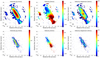 |
Fig. A.2. ALMA moment maps. ALMA first three moment maps obtained from the 2017.1.01439.S data-set selecting the baselines in order to separate the CO(2-1) emission over extended (top panels) and compact angular scales (bottom panels). From left to right: Integrated flux (moment-0), mean velocity (moment-1), and velocity dispersion (moment-2). The grey ellipses in lower-left corner show the synthesised beam size (i.e. the angular resolution): 2.18 × 2.03 arcsec2 at PA = -82 deg and 0.52 × 0.45 arcsec2 at PA = 81 deg (top and bottom panels respectively). |
Appendix B: Ionisation parameter
We used the [O III]/Hβ and [N II]/Hα peak line ratios to compute the ionisation parameter by adopting the Voronoi tessellation and the analytical expression by Baron & Netzer (2019) reported below:
![Mathematical equation: $$ \begin{aligned} \log U = a_1 + a_2\log \biggl (\frac{\mathrm{[O\,III]}}{\mathrm{H\beta }}\biggr )&+ a_3\log \biggl (\frac{\mathrm{[O\,III]}}{\mathrm{H\beta }}\biggr )^2+ \\&a_4\log \biggl (\frac{\mathrm{[N\,II]}}{\mathrm{H\alpha }}\biggr )+ a_5\log \biggl (\frac{\mathrm{[N\,II]}}{\mathrm{H\alpha }}\biggr )^2, \end{aligned} $$](/articles/aa/full_html/2023/11/aa45729-22/aa45729-22-eq12.gif)
where a1 = −3.766, a2 = 0.191, a3 = 0.778, a4 = −0.251, and a5 = 0 − 342. This expression is only valid for ionisation parameters in the range log U = −2 to log U = −3.8 with a typical uncertainty of 0.11 dex (Baron & Netzer 2019). The resulting map is reported in Figure B.1. Higher values of the ionisation parameter are found at the nucleus and in the cones, where U decreases with increasing distance from the AGN. U is on average low within the host galaxy disc.
 |
Fig. B.1. Map of the ionisation parameter obtained by applying the Voronoi tessellation. |
Appendix C: The [O I]λ6003 Å/Hα ratio
By applying the procedure described in Section 3.4, we produced the continuum-subtracted [O I]λ6003 Å emission line data-cube. We used the Cube2Im task to derive the surface brightness map of the [O I] emission line by applying a signal-to-noise ratio threshold of 3. We used the surface brightness Hα maps to derive the [O I]λ6003 Å/Hα ratio map reported in Figure C.1.
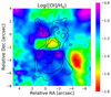 |
Fig. C.1. Map of the [O I]λ6003 Å/Hα ratio in log scale. Black contours are from EVLA radio continuum map at 6cm (Figure 1 left panel), drawn at (1, 5, 10)σ. |
All Tables
All Figures
|
Fig. 1. Radio continuum emission maps. Left panel: map of the 1.3 mm continuum emission at ∼0.2 arcsec resolution with a cut-out at 2σ. Contours are drawn at (2, 3, 6, 15, 60)σ, σ = 0.02 mJy beam−1. Central panel: ALMA map of the 1.3 mm continuum seen at ∼0.6 arcsec resolution with a cut-out at 1σ, σ = 0.05 mJy beam−1. Compared to the left panel, in this map both the nuclear emission and the dusty disc are detected. Contours as in left panel. Right panel: VLA 6 cm map of radio continuum. Contours are drawn at (1, 2, 3, 5, 8, 20, 50, 100)σ, σ = 0.14 mJy beam−1. The grey ellipses show the ALMA beam in the left and middle panels and the VLA beam in the right panel. |
| In the text | |
|
Fig. 2. ALMA moment maps. From left to right: CO(2−1) integrated flux (moment-0), mean velocity (moment-1), and velocity dispersion maps (moment-2). Top panels show data with 0.2 arcsec angular resolution, while the lower panels show data with 0.6 arcsec resolution. Regions with emission below 3σ are blanked out. The synthesised beam of each dataset is shown by the grey filled ellipses in the lower-left corner of the map. In the bottom-left panel, arrows indicate the direction towards NGC 2993 and Arp 245 North. |
| In the text | |
|
Fig. 3. Cold molecular disc kinematics. Left panel: rotation velocity (green symbols) and velocity dispersion (blue symbols) as a function of the radius obtained from the best-fit disc dynamical model of the CO(2−1) data with 0.6 arcsec angular resolution. Middle and right panels: position–velocity diagrams along the kinematic major axis for the 0.2 arcsec and 0.6 arcsec resolution observations, respectively. The slit widths are set to the FWHM size of the synthetic beam major axis for each respective observation. Red contours and yellow circles represent the disc model, while blue contours represent the data. Contours are drawn at (1, 2, 4, 8, 16, 32, 64)σ. |
| In the text | |
|
Fig. 4. Residual moment maps. Left panel: residual mean velocity map. Right panel: residual velocity dispersion map, where magenta circles mark the position of the cold molecular perturbations described in Sect. 3.3. Residual maps are obtained by subtracting the best-fit disc model maps from the observed ones. |
| In the text | |
|
Fig. 5. EDGE1 and EDGE2 TAIL kinematics. Normalised CO(2−1) and [O III] spectra at the EDGE1 (upper panel) and EDGE2 TAIL (middle panel) regions. Purple histograms = CO(2−1) line. Blue symbols and solid line = [O III]. The dashed black line and grey shaded area represent the LOS velocity of the best-fit disc model and the [vmodel − σmodel, vmodel + σmodel] range, where (vmodel, σmodel) are (−185, 37) km s−1 and (206, 36) km s−1 at EDGE1 and EDGE2 TAIL, respectively. Bottom panel: CO(2−1) position–velocity plot (from 2017.1.01439.S) cut through EDGE1, EDGE2 TAIL, and the disc centre (along PA = 193 deg). The slit width is set to 0.6 arcsec (equal to the FWHM size of the synthetic beam major axis). Yellow symbols represent the disc model, while blue contours represent the data, with contours drawn at (2, 5, 10, 15, 30, 60)σ. |
| In the text | |
|
Fig. 6. Outflowing CO(2−1) clumps. Left panel: CO(2−1) intensity map with a cut at > 3σ. The labelled black polygons show the CO(2−1) clumps identified as cold molecular wind, i.e. not participating in the disc rotation. Right panel: blue, green, and red spectra are extracted from each molecular clump identified in the left panel, as labelled. Spectra are coloured according to the velocity shift of their peak: red with vpeak > 10 km s−1, green with −10 < vpeak < 10 km s−1, blue with vpeak < −10 km s−1. The grey-shaded histograms show the total CO(2−1) emission above a 3σ threshold extracted from the data-cube of coarser resolution. |
| In the text | |
|
Fig. 7. Ionised gas moment maps. Moment maps of (top to bottom) Hα, [O III], Hβ, and [N II]λ6583 Å data-cubes. From left to right: integrated flux (moment-0), mean velocity (moment-1), and velocity dispersion maps (moment-2). The maps were obtained using the CUBEXTRACTOR package by Cantalupo et al. (2019) using a detection threshold that optimises the S/N (3σ threshold for Hα, 2σ threshold for [O III], 5σ for Hβ, and 4σ for [N II]). |
| In the text | |
|
Fig. 8. Ionised gas properties. Left panel: HST image of NGC 2992 in the FQ606W filter (from the Mikulski Archive for Space Telescopes, Proposal 05479), showing the dust lane. Magenta contours are from the CO(2−1) intensity map (Fig. 2). Left-centre panel: Voronoi map of the total extinction in V band, AV. Right-centre panel: electron density map, ne, derived from the ionisation parameter (Sect. 3.4 and Appendix B). Right panel: mass surface density of the ionised gas. |
| In the text | |
|
Fig. 9. 3DBAROLO dynamical model of the ionised gas disc obtained by fitting the Hα data cube. Left panel: rotation curve (green symbols) and velocity dispersion (blue symbols) corrected for beam smearing, as a function of the radius obtained from the best-fit disc model. Right panel: position–velocity diagram along the kinematic major axis, PA = 210 deg. Red contours and yellow filled circles represent the disc model, blue contours represent the data. Contours are drawn at (1, 2, 4, 8, 16, 32, 64)σ. |
| In the text | |
|
Fig. 10. Ionised gas kinematics traced with the [O III] emission line. Left panel: position–velocity diagram of the [O III] emission along the kinematic major axis, PA = 210 deg. Central panel: [O III] intensity map (grey scale), red and blue contours show the high-velocity [O III] emission between [200, 1000] and [−1000, −200] km s−1, respectively. Right panel: map of the W80 of the [O III] line. |
| In the text | |
|
Fig. 11. Ionised gas disc and wind kinematics. Top panel: simplified model of the source based on the ionised gas kinematics. Magenta = nucleus (N), purple = inner disc, Light/dark green: outer disc, red/burgundy = west ionisation cone (W1/W2), blue/cyan = east ionisation cone (E1/E2). Bottom panel: normalised [O III] line profiles at the wind regions, spectra are coloured according to the model map in the left panel. |
| In the text | |
|
Fig. 12. Interplay of the radio bubbles with the multiphase ISM. From left to right: CO(2−1) mean intensity map (same as Fig. 2, bottom-left panel), ALMA 1.3 mm continuum (same as Fig. 1, right panel), Hα moment 1 map (same as Fig. 7, top-central panel), and [O III] W80 map (same as Fig. 10, right panel). Black contours are from the EVLA radio continuum map at 6 cm (Fig. 1, left panel), drawn at (1, 5, 10)σ. |
| In the text | |
|
Fig. 13. Star formation across the disc of NGC 2992. Upper panel: map of the cold molecular to ionised ([O III]) gas surface densities ratio. The CO map has been degraded to the same angular resolution of the [O III] map. Black contours are from the residual velocity dispersion map (right panel Fig. 4) and are drawn at (5, 10, 20, 40) km s−1. Bottom panel: spatially resolved star-formation law on scales of ∼200 pc. Purple symbols are the two sides of the disc where radio continuum is detected (this work). Black symbols are data derived for local AGN host galaxies, along with their best-fit relation (dashed line) and dispersion (shaded area) from Casasola et al. (2015). |
| In the text | |
|
Fig. A.1. CO(2-1) emission line spectrum extracted from the ALMA data-cubes selecting the region above a 3σ threshold. |
| In the text | |
|
Fig. A.2. ALMA moment maps. ALMA first three moment maps obtained from the 2017.1.01439.S data-set selecting the baselines in order to separate the CO(2-1) emission over extended (top panels) and compact angular scales (bottom panels). From left to right: Integrated flux (moment-0), mean velocity (moment-1), and velocity dispersion (moment-2). The grey ellipses in lower-left corner show the synthesised beam size (i.e. the angular resolution): 2.18 × 2.03 arcsec2 at PA = -82 deg and 0.52 × 0.45 arcsec2 at PA = 81 deg (top and bottom panels respectively). |
| In the text | |
|
Fig. B.1. Map of the ionisation parameter obtained by applying the Voronoi tessellation. |
| In the text | |
|
Fig. C.1. Map of the [O I]λ6003 Å/Hα ratio in log scale. Black contours are from EVLA radio continuum map at 6cm (Figure 1 left panel), drawn at (1, 5, 10)σ. |
| In the text | |
Current usage metrics show cumulative count of Article Views (full-text article views including HTML views, PDF and ePub downloads, according to the available data) and Abstracts Views on Vision4Press platform.
Data correspond to usage on the plateform after 2015. The current usage metrics is available 48-96 hours after online publication and is updated daily on week days.
Initial download of the metrics may take a while.