| Issue |
A&A
Volume 658, February 2022
|
|
|---|---|---|
| Article Number | A59 | |
| Number of page(s) | 16 | |
| Section | Cosmology (including clusters of galaxies) | |
| DOI | https://doi.org/10.1051/0004-6361/202140908 | |
| Published online | 01 February 2022 | |
Catalog of X-ray-selected extended galaxy clusters from the ROSAT All-Sky Survey (RXGCC)⋆,⋆⋆
1
The Kavli Institute for Astronomy and Astrophysics at Peking University (KIAA-PKU), Peking University, Yiheyuan Road 5, 100871 Beijing, PR China
e-mail: This email address is being protected from spambots. You need JavaScript enabled to view it.
2
Argelander-Institut für Astronomie (AIfA), Universität Bonn, Auf dem Hügel 71, 53121 Bonn, Germany
3
Max-Planck-Institut für Extraterrestrische Physik, Giessenbachstraße, 85748 Garching, Germany
Received:
28
March
2021
Accepted:
25
October
2021
Abstract
Context. There is a known tension between cosmological parameter constraints obtained from the primary cosmic microwave background and those drawn from galaxy cluster samples. One possible explanation for this discrepancy may be that the incomplete character of detected clusters is higher than estimated and, as a result, certain types of groups or galaxy clusters have been overlooked in the past.
Aims. We aim to search for galaxy groups and clusters with particularly extended surface brightness distributions by creating a new X-ray-selected catalog of extended galaxy clusters from the ROSAT All-Sky Survey (RASS), based on a dedicated source detection and characterization algorithm that is optimized for extended sources.
Methods. Our state-of-the-art algorithm includes multi-resolution filtering, source detection, and characterization. On the basis of extensive simulations, we investigated the detection efficiency and sample purity. We used previous cluster catalogs in X-ray and other bands, as well as spectroscopic and photometric redshifts of galaxies to identify clusters.
Results. We report a catalog of galaxy clusters at high galactic latitude based on the ROSAT All-sky Survey, known as the RASS-based extended X-ray Galaxy Cluster Catalog, which includes 944 groups and clusters. Of this number, 641 clusters have been previously identified based on intra-cluster medium (ICM) emission (Bronze), 154 known optical and infrared clusters are detected as X-ray clusters for the first time (Silver) and 149 are identified as clusters for the first time (Gold). Based on 200 simulations, the contamination ratio of the detections that were identified as clusters by ICM emission and the detections that were identified as optical and infrared clusters in previous work is 0.008 and 0.100, respectively. Compared with the Bronze sample, the Gold+Silver sample is less luminous, less massive, and exhibits a flatter surface brightness profile. Specifically, the median flux in [0.1−2.4] keV band for Gold+Silver and Bronze sample is 2.496 × 10⁻¹² erg s−1 cm−2 and 4.955 × 10⁻¹² erg s−1 cm−2, respectively. The median value of β (the slope of cluster surface brightness profile) is 0.76 and 0.83 for the Gold+Silver and Bronze sample, respectively.
Key words: surveys / galaxies: clusters: general / cosmological parameters / X-rays: galaxies: clusters
Full Table 3 is only available at the CDS via anonymous ftp to cdsarc.u-strasbg.fr (130.79.128.5) or via http://cdsarc.u-strasbg.fr/viz-bin/cat/J/A+A/658/A59
This entire sample is available online (https://github.com/wwxu/rxgcc.github.io/blob/master/table_rxgcc.fits).
© ESO 2022
1. Introduction
Among the different cosmological probes, galaxy clusters are some the most important with regard to testing standard cosmological scenarios (Dunkley et al. 2009; Kowalski et al. 2008; Reiprich & Böhringer 2002; Seljak 2002; Dahle 2006; Pedersen & Dahle 2007; Rines et al. 2007; Wen et al. 2010; Allen et al. 2008, 2011; Abbott et al. 2018). As the largest gravitational systems in the universe, their spatial distribution and number density are sensitive to their dark matter and dark energy content (e.g., Borgani et al. 2001; Reiprich & Böhringer 2002; Seljak 2002; Viana et al. 2002; Kravtsov & Borgani 2012; Schellenberger & Reiprich 2017). However, a tension exists between cosmological constraints derived from the primary cosmic microwave background (CMB, Planck Collaboration XXVII 2016; Planck Collaboration I 2020; Planck Collaboration VI 2020; Abbott et al. 2020) and those from galaxy cluster studies (see, e.g., Fig. 17 in Pratt et al. 2019). One possible explanation for this tension is the underestimation of the incomplete character of cluster detections.
The intra-cluster medium (ICM) allows us to detect galaxy clusters using two different wavelengths: the X-ray and sub-millimetre bands. Compared with cluster observations in other bands (e.g., optical), the ICM observations are able to trace genuine deep gravitational potential wells and they are less affected by projection effects. The X-ray emission includes the bremsstrahlung and line emission (e.g., Reiprich et al. 2013), while sub-millimeter emission comes from the Sunyaev–Zel’dovich effect (Sunyaev & Zeldovich 1970, 1972, 1980).
Various methods are used to detect galaxy clusters from X-ray data. The most widely used are the sliding-cell algorithm (e.g., Voges et al. 1999), the Voronoi tesselation and percolation method (VTP, Ebeling & Wiedenmann 1993; Scharf et al. 1997; Perlman et al. 2002), and the wavelet transformation (Rosati et al. 1995; Vikhlinin et al. 1998; Pacaud et al. 2006; Mullis et al. 2003; Lloyd-Davies et al. 2011; Xu et al. 2018). These methods have distinct advantages and disadvantages with regard to cluster detections (e.g., Valtchanov et al. 2001).
Until mid-2019, ROSAT was the only X-ray telescope performed an all-sky imaging survey (RASS, Truemper 1992, 1993) in the 0.1−2.4 keV energy band. There are several ROSAT-based cluster catalogs, with the most significant ones being: ROSAT-ESO Flux Limited X-ray Galaxy Cluster Survey (REFLEX, Böhringer et al. 2004), Northern ROSAT All-Sky galaxy cluster survey (NORAS, Böhringer et al. 2000, 2017), ROSAT Brightest Cluster Sample (BCS, Ebeling et al. 1998, 2000), a Catalog of Clusters of Galaxies in a Region of 1 steradian around the South Galactic Pole (SGP, Cruddace et al. 2002), the ROSAT North Ecliptic Pole survey (NEP, Henry et al. 2006), and Massive Cluster Survey (MACS, Ebeling et al. 2001). These catalogs, along with several others, have been compiled as the Meta-Catalogue of X-ray detected Clusters (MCXC, Piffaretti et al. 2011). In addition to ROSAT, the XMM-Newton and Chandra observatories are also widely used to identify galaxy clusters. With improved resolution and sensitivity, as well as longer exposure times, they could identify faint clusters at high redshift, as shown, for instance, in the works of Mehrtens et al. (2012), Clerc et al. (2012, 2016), Takey et al. (2011, 2013, 2014, 2016), Pacaud et al. (2016), Koulouridis et al. (2021).
As the successor to ROSAT, the eROSITA X-ray satellite (extended Roentgen Survey with an Imaging Telescope Array, Merloni et al. 2012) is scanning the whole sky in the 0.1−10 keV energy band and will complete eight scannings in its first four years, reaching a sensitivity that is 25 times better1 than ROSAT (Predehl et al. 2021). It will be able to make a complete detection of clusters with M > 2 × 10¹⁴ M⊙, detecting > 100 000 galaxy clusters and thus allowing us to set tighter constraints on dark energy (e.g., Merloni et al. 2012, 2020; Pillepich et al. 2012, 2018). The first results indeed look very promising (e.g., Ghirardini et al. 2021; Reiprich et al. 2021). However, it will take some time before the first full sky eROSITA cluster catalogs are published.
In Xu et al. (2018, hereafter Paper I), we applied an X-ray, wavelet-based, source-detection algorithm to the RASS data. As a result, we found many known and many new candidates for galaxy groups and clusters, which had not been included in any previous X-ray or SZ (detected by the Sunyaev–Zel’dovich effect in micro-wave band) cluster catalogs. Among these, we showed a pilot sample of 13 very extended groups, whose surface brightness distributions are flatter than expected and with some of them exhibiting X-ray fluxes above the nominal flux-limits of previous RASS cluster catalogs. We argued that such galaxy groups had been overlooked in previous RASS surveys due to their flat surface brightness distribution, which was not detected by the sliding-cell algorithm.
As a companion to this paper, we are releasing our final galaxy cluster catalog: the RASS-based X-ray-selected extended Galaxy Clusters Catalog (RXGCC) and we discuss the cluster properties (e.g., position and redshift, angular size, X-ray luminosity, mass, etc.). The paper is structured as follows. Section 2 describes the data and methodology briefly. Section 3 presents the RXGCC catalog and the distribution of parameters. In Sect. 4, we discuss the very extended clusters and false detections in our work, and we make a comparison of the RXGCC catalog with other ICM-detected cluster catalogs and a general X-ray source catalog. Section 5 presents our conclusions.
Additional information is given in the appendix. We discuss the difference between the method applied here and that of Paper I in Appendix A. In Appendix B, we estimate the contamination ratio for detections with simulations. In Appendix C, we show the comparison of detected and undetected MCXC, PSZ2, and Abell clusters. In Appendix D, we compare detected and undetected REFLEX and NORAS clusters. In Appendix E, we show the gallery of two clusters as examples. In Appendix F, we list clusters whose redshift or classification are changed based on a visual check. Throughout the paper, we assume the cosmological parameters H0 = 70 km s−1 Mpc−1, ΩM = 0.3, and ΩΛ = 0.7.
2. Data and methodology
In this section, we present a brief description of the data and the methodology to detect, classify, and characterize sources. Further details are provided in Paper I and our modifications to the method are discussed in Appendix A.
2.1. Data
We used the RASS images in the 0.5−2.0 keV energy band. These images come from the third processing of the RASS data (RASS-32). We excluded the regions within the galactic latitude |b|< 20°, as well as the Virgo cluster and the Large and Small Magellanic Clouds (see Table 2 in Reiprich & Böhringer 2002). The total data coverage in this work is 26 721.8 deg2 (8.13994 sr), namely, about two-thirds of the sky.
2.2. Source detection
Our source detection and characterization method consists of three main steps. First, we applied a multi-resolution wavelet filtering procedure (Pacaud et al. 2006; Faccioli et al. 2018) to remove the Poisson noise in the RASS images. Secondly, we used the SEXTRACTOR software (Bertin & Arnouts 1996) on the filtered images. Finally, a maximum-likelihood fitting algorithm models each detected source. This last step makes use of C-statistics (Cash 1979) and fits two models to each source: a point source model, given by the point-spread function (PSF) of the PSPC detector, and a cluster model, described by a β-model with β = 2/3 (Cavaliere & Fusco-Femiano 1976). The β-model describes the surface-brightness of galaxy clusters with a spherically symmetric model, SX(r)∝[1 + (r/rc)2]−3β + 0.5, where rc is the core radius of the cluster and β describes the slope of the brightness profile. The value of β is 2/3 for a typical cluster and the smaller the value of β, the flatter the profile.
The maximum-likelihood fitting algorithm outputs several parameters for each source. Using extensive Monte Carlo simulations (see Paper I for further details), we calibrated and established the appropriate criteria for classifying the detections. The simulations include a realistic sky and particle background, a population of AGN, and galaxy clusters with different profile, size, and flux. We chose the “detection likelihood” (i.e., the significance of each detection compared with a background distribution), the “extension likelihood” (i.e., the significance of the source extension), and the “extent” (i.e., the core radius of the cluster model), as the best parameters to classify our detections. It is expected the false detection rate is 0.0024 deg2 within the thresholds of the detection likelihood > 20, extension likelihood > 25, and extent > 0.67 arcmin.
2.3. Classification of detections
To classify the detections, we considered not only the spatial and redshift distribution of galaxies, but also the information from previously identified clusters. As described in this subsection, we collected galaxy redshifts and identified clusters in order to estimate the redshift and classify our detections based on the classification criteria. In the last step, we visually inspect images in multiple bands to confirm our redshift estimation and classification.
2.3.1. Redshift estimation
To estimate redshifts of the detections, we gathered all the spectroscopic and photometric redshifts of galaxies located within 15 arcmin surrounding our detections, with 0 < z < 0.4, from the Sloan Digital Sky Survey (SDSS) DR163, Galaxy And Mass Assembly DR14 (GAMA), the Two Micron All Sky Survey Photometric Redshift Catalog (2MPZ catalog, Bilicki et al. 2014), and the NASA Extragalactic Database5 (NED). We considered galaxies as the same object if the offset < 3″ and Δz < 0.01; also, we only reserved the information of one galaxy in the following priority order: SDSS, GAMA, 2MPZ, NED. The spectroscopic redshift in surveys has a higher priority than the photometric redshift.
In this way, we obtained the distribution of galaxy redshifts, both spectroscopic and photometric, for each detection. The galaxy redshifts are binned with the width of Δz = 0.01. We iteratively fit a Gaussian function with 3σ clipping to the two highest peaks in the distribution. Each peak should contain ≥3 redshifts. The best-fit value is taken as the candidate redshift. We note that the second peak is also taken as an alternative option of the candidate redshift, in cases where the included galaxy number is no less than 20% of the highest peak. The redshift difference of the two candidate values is set as Δz > 0.02 to avoid overlap. Furthermore, the 1σ redshift dispersion is estimated, including the intrinsic cluster velocity dispersion and the uncertainty of redshift estimation. The redshift error is set as σz > 0.005.
In addition, we performed a visual inspection (see Sect. 2.3.4) to confirm the redshift of detections. If there are not enough galaxy redshifts measured, the final redshift is obtained from the collected redshift information of known galaxy clusters, if available. The ICM-detected cluster information has a higher priority than optical cluster information. All this information, if applicable, is added to the “z,src” column of Table 3.
2.3.2. Collection of identified clusters
We performed an extensive cross-matching of our detections with other publicly available cluster catalogs to determine how many detections were previously identified as clusters or groups. We collected the information of galaxy clusters from the literature (listed in Table 1). As mentioned in Sect. 1, the MCXC catalog is a meta-catalog that includes a number of individual catalogs, such as the REFLEX and NORAS catalogs. In addition, we take into account systems from the NED database, which are classified as: cluster of galaxies, group of galaxies, galaxy pair, galaxy triple, or group of QSOs. We discarded NED systems with names beginning in WHL, MCXC, or PSZ2 to avoid overlap with catalogs from the literature.
Overview of cluster catalogs and X-ray point-source catalogs.
Given that the Abell and ICM-detected clusters have a limited accuracy in terms of redshift, we also cross-matched detections with them only on the basis of projected distance and without considering their redshifts. We list the cross-matching result in the last column of Table 3 as a reference. This information is not used to classify our detections, which is discussed in Sect. 2.3.3. Besides the cluster catalogs, we also list ROSAT X-ray point-source catalogs in the last part of Table 1 (see Sect. 4.4 for details).
2.3.3. Classification criteria
We cross-matched our detections with the previously identified clusters described in Sect. 2.3.2, using a matching radius of 15′ and 0.5 Mpc, and Δz < 0.01. If all criteria are met for two clusters, we considered them as the same. With these criteria and visual inspection, we classified our detections into four classes:
Gold: if the detection is not cross-identified with any known optical, infrared, X-ray, or SZ cluster; behaves as a clear galaxy overdensity in optical and infrared images or has a clear peak in the distribution of galaxy redshifts (or both).
Silver: if the detection has been cross-identified with a known optical or infrared cluster, but is not cross-identified with any X-ray or SZ cluster.
Bronze: if the detection has been cross-identified with known X-ray or SZ cluster.
False detections: if the detection appears to be a spurious detection or if it is artificially created by multiple high-redshift clusters that are located nearby in the projection.
2.3.4. Visual inspection
We created an extensive multi-wavelength gallery for each of our detections. For each source, we checked the RASS photon image, RASS exposure map, and wavelet-reconstructed image, as well as the galactic neutral hydrogen column density image from the HI4PI survey (HI4PI Collaboration 2016). These images, combined with galaxy redshifts described in Sect. 2.3.1, helped us find detections that are artificially created by the large variation of exposure time or a low hydrogen column density along the line-of-sight. Furthermore, when available, we inspected image from the Planck6 survey (we refer to Erler et al. 2018 for the corresponding image extraction method), infrared RGB image from 2MASS7, optical image from the POSS2/UKSTU Red survey8, and optical RGB image (combination of i, r, and g bands) from VST ATLAS9, Pan-STARRS110, DES DR111, and SDSS DR12.
The detections of M 101 (RA: 210.828°, Dec: 54.313°) and M 51 (RA: 202.495°, Dec: 47.211°) were confirmed as galaxies using the visual inspection and were thus removed from the final catalog.
In addition, a visual inspection was performed to confirm (and modify if needed) the redshift and classification of detections. The modifications are listed in Table F.1. This inspection considered: (1) whether the spatial distribution of member galaxies obeys the cluster morphology, (yes for the existence of a cluster); (2) whether a bright elliptical galaxy is found at the central region, (yes for the existence of cluster); (3) whether the X-ray emission mainly comes from a star, star cluster, galaxy, or AGN, (yes for false detection).
2.4. Characteristics of cluster candidates
After the source detection and classification, we estimated physical parameters such as the size, flux, luminosity, and mass to characterize the cluster candidates. In addition, we also estimated their β-value to show the compactness.
2.4.1. Estimation of physical parameters
We estimated X-ray observables using the growth curve analysis method (Böhringer et al. 2000, 2001), which is briefly described in this subsection as follows. Firstly, the growth curve, namely, the cumulative count-rate of photons as a function of radius, is constructed for each cluster in the [0.5−2.0] keV energy band. The regions within the radius of 20′, 40′, and 60′ are taken as the source area, respectively. In some complex cases, another radius is taken for the source area, such as 30′, 50′, or 80′. A larger annulus with the width of 20′ is used to estimate the local background. Contamination in the background and source area, either from projected foreground or background sources, is corrected using a de-blending procedure, which excludes angular sectors with a count rate that varies from the median value by > 2.3σ.
After the background is subtracted, we bin the growth-curve with the width of 0.5′. The growth curve is supposed to be flat at large radius, where the contribution of cluster is negligible. We define the significant radius, Rsig, as the radius whose 1σ uncertainty interval encompasses all count rates integrated in larger apertures. We take the growth curve beyond the significant radius as the plateau and we take the average plateau count rate as the significant count rate, CRsig. For each candidate, the source aperture with the most steady growth curve is used for following analysis.
With the estimation of Rsig and CRsig, we calculate the main parameters with the scaling relations from Reichert et al. (2011) (Eqs. (23)–(26)), wherein show the power-law relations between LX, TX, and M. Firstly, we assume R500 = Rsig, and we obtain the total mass within R500 (M500); and, furthermore, the bolometric X-ray luminosity (LX) and temperature (TX) by using scaling relations. With the APEC model, we obtain the luminosity within R500 in [0.1−2.4] keV band (L500), as well as the flux in the same band (F500). The total count rate inside R500 (CR500) is further estimated with PIMMS (Mukai 1993), taking into account the instrument response of ROSAT PSPC and the galactic absorption. Using the typical β-profile with β = 2/3, we take the value of CR500 as an estimation of CRsig. The goal is that the estimated CRsig, est is equal to the observed CRsig, obs. Therefore, the steps described above are iteratively repeated until CRsig, est = CRsig, obs. In this way, we obtain the value of CR500 and R500, as well as the corresponding parameters, such as M500, L500, TX, and F500.
2.4.2. Estimation of β value
To better understand the clusters in our sample, we characterized their X-ray emission profile. As mentioned in Sect. 2.2, the β value describes the flattening of the source, while the β parameter is highly correlated with the core radius.
Using the Markov chain Monte Carlo (MCMC) method, we estimated the value and uncertainty of the β and the core radius by fitting the growth curve with a β-model convolved with the PSF. For simplicity, we take a Gaussian function with the FWHM of 45 arcsec as the PSF of the PSPC detector. In the MCMC fitting12, we used 50 chains in total, at 10 000 steps each. The free parameters include the β value, the core radius, and the normalization. We initialized the chains in a minuscule range around the maximum likelihood result and discarded the first 5000 steps of each chain to avoid the effects resulting from the starting point. Then a uniform prior was assumed for each parameter, whose threshold is set as respectively 0.50 and 1.00 for the β value, 0.01 and 50.0 arcmin for the core radius, 0.001 and 5 for the normalization. The lower limit of the β value comes from the convergence requirement of the integrated count rate.
3. Results
We obtain 1308 detections with the RASS data in the high galactic latitude area. Following the source detection, classification and characterization methods described in Sect. 2, we obtained 641 Bronze clusters, 154 Silver clusters, and 149 Gold clusters. These 944 cluster candidates were compiled into the final catalog, named the RASS-based X-ray selected Galaxy Cluster Catalog (RXGCC). A detailed discussion about false detections is provided in Sect. 4.2. The distribution of each class in the “extent-extension likelihood” parameter space (see Sect. 2.2) is shown in Fig. 1, and the source number and median redshift are summarized in Table 2.
 |
Fig. 1. Extent-extension likelihood plane that defines our criteria to select extended X-ray sources (see Paper I for further details). Top panel: RXGCC clusters, i.e., Gold+Silver+Bronze. Top-left, top-right, and bottom-left panels: sub-samples of RXGCC: Gold – new identified clusters; Silver – previous optical/infrared-identified clusters; Bronze – previous ICM-identified clusters. Bottom-right panel: false detections – spurious detections. |
Detections in terms of classes.
The redshift distribution of RXGCC clusters is shown in Fig. 2. It shows that the newly-identified clusters (Gold) tend to have a little higher redshift than the clusters previous identified as optical/infrared clusters (Silver), while the previously ICM-identified clusters (Bronze) have a consistent redshift distribution within the whole RXGCC sample, whose median redshift is 0.0770. The redshift histogram demonstrates the detection efficiency decreases greatly when the redshift z > 0.12.
 |
Fig. 2. Redshift distribution for different classes of our cluster candidates. The overlaid vertical line indicates the median redshift of different classes. For simplicity, we use ‘G’, ‘S’, and ‘B’ for short for the Gold, Silver, and Bronze samples. |
The highest redshift of the sample is 0.5551 and there are four RXGCC clusters with z > 0.4 (RXGCC 229, RXGCC 237, RXGCC 306, RXGCC 590). These redshifts were obtained from previous ICM-detected clusters, instead of galaxy redshifts. A careful visual check of X-ray and micro-wave images, along with the spatial distribution and distance between these four detections and previously identified clusters, strengthens the evidence to the extent to determine that the detected X-ray emission indeed comes from the previously identified clusters. For these four candidates, the redshift limit of cross-matched clusters is set as z < 0.6, instead of z < 0.4, and the offset threshold is < 1.5 Mpc, instead of < 0.5 Mpc.
In addition, the three clusters RXGCC 406, RXGCC 639, and RXGCC 646 are covered on the basis of deep optical observations. In the redshift estimation, galaxy redshifts are constrained with < 0.16, instead of < 0.4.
For the cross-matching of RXGCC with previous ICM-detected clusters, there are several exceptions, namely, RXGCC 93, RXGCC 239, RXGCC 612, and RXGCC 688, which have ICM-identified clusters in < 15′, but the position and redshift distribution of galaxies clearly indicate that the previous ICM-detect clusters are not what we detected. Thus, we removed them from the Bronze and classified them as Gold or Silver henceforth.
3.1. RXGCC catalog
The RXGCC catalog comprises 944 clusters, including 641 Bronze, 154 Silver, and 149 Gold clusters, whose spatial distributions are shown in the top panel of Fig. 3. The full table is sorted with right ascension and is provided in FITS format as supplementary material13. The first ten rows of the RXGCC catalog are shown in Tables 3 and 4 for its form and content. In addition, we also published the image gallery for each RXGCC source (e.g., the gallery for RXGCC 114).
 |
Fig. 3. All-sky distributions. Top: RXGCC clusters. Bottom: false detections. |
First part of the first ten entries in the RXGCC catalog.
Second part of the first ten entries of the RXGCC catalog.
In Table 3, the first five columns list the name, position, “extent”, and “extension-likelihood” values. The RXGCC cluster coordinates are obtained from the maximum-likelihood fitting (see Sect. 2.2). Columns 6 and 7 are the estimation of redshift and its error (see Sect. 2.3.1). Column 8 shows the source of the cluster redshift, referring the table note for details. Column 9 shows the classification, described in Sect. 2.3.3. The following two columns contain information on the cross-matching with previously ICM-identified clusters and clusters previously identified in the optical or infrared band. These clusters are all offset from our candidates < 0.5 Mpc and < 15′, and the redshift difference Δz < 0.01. The last column lists the Abell clusters or ICM-detected clusters within 0.5 Mpc and 15′, regardless of their redshift values.
3.2. Parameter distributions
In this subsection, we discuss the distribution of X-ray observables of RXGCC clusters. Their distributions are shown in Fig. 4. The solid, dashed, and dotted histograms demonstrate the parameter distribution of RXGCC sample, the previous ICM-detected (Bronze) sample, and the new ICM-detected (Gold+Silver) sample, while the vertical lines show the corresponding median values. These median values are listed in Table 5. From the median values, it is clear that the new ICM-detected clusters tend to have lower count rate, flux, luminosity, mass and temperature. Still, it is worth noting that the median flux of new ICM-detected clusters is close to the typical flux limit of the previous RASS-based cluster catalogs (3 × 10⁻¹² erg s−1 cm−2). Thus, a significant fraction of new ICM-detected clusters (Gold+Silver) have a flux value above this limit.
 |
Fig. 4. Distribution of parameters of the RXGCC sample, the previous ICM-detected sample (Bronze), and the new ICM-detected sample (Gold+Silver), shown as solid, dashed, and dotted histograms and lines, in sequence. We refer to Sect. 2.4.1 for details on the estimation methods. Both the F500 and L500 are the values in [0.1−2.4] keV band. We manually set the upper parameter limit of the axis in the plot, to remove a few outliers with large parameter value in the histogram. |
Median parameter value for detections.
More importantly, the new ICM-detected sample has a lower median β value than the previous ICM-detected sample, as shown in the last row of Table 5. The median β value of clusters in these two samples is 0.76 and 0.83, respectively. This is an indication for the new ICM-detected clusters to generally exhibit flatter surface brightness profiles as compared to the previous ICM-detected clusters.
In the top panels of Fig. 5, the measured luminosity function and mass functions are shown. We note that we did not apply any correction of selection effects here – as a complete sample with accurate selection function would be required for this – so a quantitative comparison to previous catalogs, such as the REFLEX or HIFLUGCS samples, is not meaningful. In this plot, we show the cumulative number of RXGCC clusters above a specific value of luminosity or mass as a very rough demonstration of the luminosity and mass function.
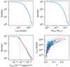 |
Fig. 5. Relation between the value of L500, M500, F500, and the integrated cluster numbers with larger luminosity, mass, or flux. Bottom-left panel: the dashed line has a slope of −1.5, normalized to match the value with fX = 2 × 10⁻¹¹ erg s−1 cm−2. The dotted vertical line labels the flux of 5 × 10⁻¹² erg s−1 cm−2. Bottom-right panel: relation between the redshift and L500. The curves for the flux limits of 10−12 and 3 × 10⁻¹² erg s−1 cm−2 are overlapped as dotted curve and dashed curve, respectively. Both the F500 and L500 are the value in [0.1−2.4] keV band. |
In bottom-left panel of Fig. 5, we show the cumulative number as a function of the X-ray flux (also called log N–log S plot). In this plot, we overlay the dashed line with the slope of −1.5 predicted by a static Euclidean universe with clusters uniformly distributed, which is a reasonable assumption for low-redshift clusters for a rough completeness check. This line is normalized to match it with the measurement at F500 = 2 × 10⁻¹¹ erg s−1 cm−2. The theoretical line matches with our detection curve with F500 > 5 × 10⁻¹² erg s−1 cm−2, shown with the vertical dotted line. This is a good indication that we have achieved a high completeness up to this flux, despite of our requirement of detecting significantly extended X-ray emission. A small bump at ∼6 × 10⁻¹¹ erg s−1 cm−2 is worth noting, which likely stems from small number statistics and expected large cosmic variance at low redshift (i.e., we are likely seeing a large-scale structure here).
In addition, the relations between the redshift and luminosity are shown in the bottom-right panel, overlaid with the flux limit of 10−12 and 3 × 10⁻¹² erg s−1 cm−2 as a dotted curve and a dashed curve, respectively. We note that there are 115 new ICM-detected RXGCC clusters with a flux greater than the flux limit of REFLEX (3 × 10⁻¹² erg s−1 cm−2 in 0.1−2.4 keV band).
3.3. Comparison of radii, count rates, and flux
Firstly, we compared different radii (i.e., the significant radius, R500, extent). As shown in the top panels of Fig. 6, Rsig is compared with R500 and extent, with the definitions and estimation methods are described in Sect. 2.4.1 and Sect. 2.2. In the plot, it is clear that Rsig is larger than both R500 and extent in most cases. Since extent shows the core radius of the β-model, and Rsig demonstrates the region with significant X-ray emission, it is reasonable to find that Rsig is larger in most cases. Given the low background of the ROSAT PSPC, the X-ray emission happens to spread beyond R500. However, for some clusters we seem to detect emission out to ∼3−5 × R500, which is surprising, at first sight. One possible reason is that our estimation is based on the assumption of the β-model with the typical value of β = 2/3, which does not necessarily describe properly the data, especially for the very extended clusters that we aim to discover. With a much flatter profile of β ≪ 2/3, the very extended cluster has an X-ray emission extending up to a much larger area.
 |
Fig. 6. Relation between the R500, Rsig, extent, the integrated count rate within R500, the integrated count rate within Rsig, and the flux inside R500. Top-left, top-right, and bottom-left panels: the red dashed line labels the 1:1 relation, while bottom-right panel: relation of F500 = CRsig × 2 × 10⁻¹¹ (erg s−1 cm−2)/(count s−1). Top-left panel: the red dotted line shows the dividing line to get the very extended candidates discussed in Sect. 4.1. |
In addition, we compared the integrated count rate and flux within Rsig and R500, respectively. This is shown in the bottom panels of Fig. 6. Compared to the top panels, these relations are much tighter. However, the conversion between the CRsig and the CR500 are derived by assuming a typical cluster profile with β = 2/3, thus their relation is related to the relation between R500 and Rsig. The conversion between the CR500 and F500 is derived with the information of cluster redshift, ICM temperature, galactic absorption, and metallicity. The tight relations between the CRsig, CR500, and F500 indicate the robustness of our parameter estimation method.
Furthermore, we separated the RXGCC sample into two sub-samples by the β value and we show the relation of the β value, the significant radius, the core radius, and the total photon count inside the significant radius in Fig. 7. The β value and rc are estimated by fitting the growth curve with the β-model convolved with PSF as described in Sect. 2.4.2, and Rsig is derived from the growth curve as shown in Sect. 2.4.1. A smaller β value corresponds to a flatter emission profile. As shown in the bottom panel of Fig. 7, it seems there are two subsamples, thus we separate the RXGCC sample into “high-β” and “low-β” sample with β = 2/3 and show them using different symbols. Except for the value difference of β, these two subsamples do not show much difference in the core radius, photon number within the significant radius, and the relation between the significant radius and the core radius. The significant radius is larger than the core radius for most of detections.
 |
Fig. 7. Relation between the β value, the core radius (rc), the significant radius (Rsig), and the total number of photons within the significant radius. The grey dots, and blue empty circles show the “high β” and “low β” samples, respectively, which are divided by the line of β = 2/3. |
Finally, we compared the same set of parameters for the Silver+Bronze sample (shown with solid dots) with the Gold sample (shown with empty circles and squares). As shown in Fig. 8, the later sample tends to have lower β value, which indicates their flat profile. We further divided the Gold sample into a Bright Gold sample (shown with empty squares) and Faint Gold sample (shown with empty circles) by F500 = 3 × 10⁻¹² erg s−1 cm−2. Compared with the Faint Gold sample, the Bright Gold sample tends to have a much larger significant radius than the core radius, a larger number of photon within the significant radius, and a much flatter profile. Especially, in the β < 2/3 regime, the Bright Gold sample has a much smaller β value (i.e., a much flatter profile) than does the Faint Gold. Thus, our detection efficiency for flat clusters is higher for bright ones, which comes from the limitation of the telescope sensitivity. In another words, our detection of such flat clusters with shallow RASS data shows that the application of this algorithm is promising when making detections of large numbers of very extended sources with deeper observations or using detectors with greater sensitivity.
 |
Fig. 8. Relation between the β value, the core radius (rc), the significant radius (Rsig), and the total number of photons within the significant radius. In these panels, the grey dots, blue empty circles, and red empty squares represent the Silver+Bronze sample, Faint Gold sample, and Bright Gold sample, respectively. The Bright Gold and Faint Gold samples are divided from the Gold sample by F500 = 3 × 10⁻¹² erg s−1 cm−2. Bottom-right panel: β histogram of the same samples, with colors matching with the other panels. |
4. Discussion
4.1. Very extended candidates
In the top-left panel of Fig. 6, we show the relation between the significant radius (Rsig) and R500. We find Rsig tends to be larger than R500. Thus, we separated out very extended clusters located at the bottom-right corner, using the dotted dividing line therein. The comparison of the β distribution of the whole RXGCC and this very extended sub-sample is shown in Fig. 9. Most of these extended candidates have β < 2/3, with a much flatter profile than the typical clusters. The detection of cluster candidates with such flat profiles demonstrates the efficiency of our algorithm and its possibility to detect many more extended clusters with forthcoming observations.
 |
Fig. 9. β distribution of the whole RXGCC and the very extended sub-sample. The very extended sub-sample is comprised of clusters located at the bottom-right part of the dividing line in the top-left panel of Fig. 6. |
4.2. False detections
In our detections, with the exception of 944 cluster candidates compiled into the RXGCC catalog, there are 364 false detections. There are several possible reasons for such false detections, such as a broad variation in exposure time, background, or the column density of neutral hydrogen, contamination from foreground or background, clustering of X-ray point sources (stars or AGNs), projection overlapping of outskirts of nearby bright or extended X-ray sources, or the projection overlapping of high-redshift clusters.
The spatial distribution of false detections is shown with red dots in the bottom panel of Fig. 3. The ratio of false detections in our study is 27.8%. Most of these are located at the ecliptic poles and along ecliptic longitudes, where the exposure variation is broad (shown at the second panel of Fig. 10). The exposure variation is taken from the difference between the highest and lowest exposure time of pixels in 1° ×1° region and divided by the median value. The way in which RASS scanning causes large exposure variation at the direction vertical to the scanning direction is shown in the top panel of Fig. 10 (adopted from the Fig. 1 of Voges et al. 1999). The spatial correlation in the top and the second panel indicates that large exposure variation is one possible reason for the false detections.
 |
Fig. 10. Exposure variation of detections. Top panel: RASS-II exposure map (adapted from the Fig. 1 of Voges et al. 1999). Second panel: all-sky distribution of all detections, colors vary with the exposure variation. Third panel: exposure variation distribution for detections in classes, the average value are overlaid with vertical lines. Bottom panel: relation between the false detection ratio with exposure variation. |
In the third panel of Fig. 10, we plot the histogram of exposure variation for detections in classes. It is clear the average exposure variation of False detections is higher than other classes and the whole detection sample. In the bottom panel of Fig. 10, it shows the positive correlation between the false detection ratio with the exposure variation. Therefore, we take the large exposure variation as the main reason for false detections.
4.3. Cross-match RXGCC with representative ICM-detected cluster catalogs
In this section, we discuss the robustness of cross-matching criteria in the catalog cross-matching, as described in Sect. 2.3.3. These cross-matching criteria, offset < 15′ & offset < 0.5 Mpc & Δz < 0.01, are used for all cross-matching in this work.
Thus, we cross-matched the RXGCC catalog with four representative ICM-detected cluster catalogs. We considered two ROSAT-based X-ray cluster catalogs, the ROSAT-ESO flux limited X-ray catalog (REFLEX, Böhringer et al. 2004) and the northern ROSAT all-sky catalog (NORAS, Böhringer et al. 2000), as well as the MCXC and PSZ2 catalogs to represent large cluster catalogs in X-ray and microwave bands. Firstly, we considered all matches with offset < 1°, and showed the offset distribution. Secondly, we constrained the offset within 15′, and indicated the redshift difference of matches. The result is shown in Fig. 11. When the offset increases, the number of matching pairs decreases firstly, and increases later for the random distribution and projection effect. Similarly, with the redshift difference increase, the number of matching pairs shows an exponential decrease, and a tiny increase later on. The criteria labeled with dotted vertical lines are used in our work to ensure a high probability for the physical correlation between matched clusters and a low probability of projection effects.
 |
Fig. 11. Differences in positions and redshifts between our candidates and position-matched MCXC/PSZ2/REFLEX/NORAS clusters. Top panel: the offset threshold is set as 1°, without setting a redshift limit. Bottom panel: the position offset is set as < 15′. The dotted vertical lines labels out the criteria used in this work. |
4.4. Known X-ray sources
In this section, we detail our cross-matching of the RXGCC catalog with the ROSAT X-ray Source Catalog (RXS, Voges et al. 1999, 2000; Boller et al. 2016). The RXS is often used as the underlying resource of possible X-ray clusters (e.g., Böhringer et al. 2000, 2004). Thus, in the case of RXGCC clusters that are not included in the RXS, they will be missed by all cluster searching projects that take the RXS catalog as input. The ratio of RXGCC clusters with RXS detection in 5′ is 91.1%, as shown in Fig. 12. That is, there are 84 clusters without any RXS sources within 5′. These clusters are definitely missed by X-ray cluster detection projects starting from the RXS sources.
 |
Fig. 12. Offset distribution between RXGCC clusters and the nearest RXS source. |
5. Conclusion
In this project, we set out to reanalyze the RASS in the [0.5−2.0] keV band and to search for possibly overlooked X-ray clusters. With the wavelet filtering, source extraction, and maximum likelihood fitting, we made 1308 detections. Combining the RASS images with optical, infrared, micro-wave band images, along with the neutral hydrogen distribution and the spatial and redshift distribution of galaxies in the field, we identified 944 clusters and removed other false detections. Among these clusters, there are 149 of them detected for the first time and an additional 154 detected through the ICM emission for the first time. For each candidate, we estimate the redshift using the distribution of the spectroscopic and photometric redshift of galaxies and use the growth curve analysis to estimate the parameters, such as count rate, flux, luminosity, and mass.
In summary, 115 of the 149 + 154 clusters detected here with ICM emission for the first time have fluxes > 3 × 10⁻¹² erg s−1 cm−2; that is, above the rough flux limits applied in previous RASS cluster catalogs. We find that the new clusters deviate in terms of their properties from the previously known cluster population. In particular, the new clusters have flatter surface brightness profiles, which makes their detection more difficult when using detection algorithms optimized for point sources. This new cluster population now ought to be followed up with deep pointed observations with XMM-Newton and Chandra in order to determine their properties in greater detail. This would allow us to estimate the magnitude of any potential bias in the estimated completeness of previous surveys, as well as its impact on ΩM and σ8 constraints. Furthermore, these findings will help in upcoming cluster searches with eROSITA data.
Referring to the flux limit for point sources, which is 5 × 10⁻¹³ erg s−1 cm−2 and 1.1 × 10⁻¹⁴ erg s−1 cm−2 for RASS (0.5−2.0 keV) and eRASS-8 (0.2−2.3 keV, Predehl et al. 2021).
EMCEE package: https://emcee.readthedocs.io/en/stable/
Acknowledgments
We acknowledge support from the National Key R&D Program of China (2016YFA0400703) and the National Science Foundation of China (11721303, 11890693). The authors wish to thank Angus Wright, Jens Erler, Cosmos C. Yeh, Chaoli Zhang, Aiyuan Yang, Linhua Jiang, Zhonglue Wen, and Jinlin Han for useful help and discussions during the development of this paper. The authors thank the support from the CAS-DAAD Joint Fellowship Programme for Doctoral Students of Chinese Academy of Sciences (ST 34). W.X. acknowledges the support of the Chinese Academy of Sciences through grant No. XDB23040100 from the Strategic Priority Research Program and that of the National Natural Science Foundation of China with grant No. 11333005. We acknowledge support from the Chinese Academy of Sciences (CAS) through a China-Chile Joint Research Fund #1503 administered by the CAS South America Center for Astronomy.
References
- Abbott, T. M. C., Abdalla, F. B., Alarcon, A., et al. 2018, Phys. Rev. D, 98, 043526 [NASA ADS] [CrossRef] [Google Scholar]
- Abbott, T. M. C., Aguena, M., Alarcon, A., et al. 2020, Phys. Rev. D, 102, 023509 [Google Scholar]
- Abell, G. O. 1958, ApJS, 3, 211 [NASA ADS] [CrossRef] [Google Scholar]
- Abell, G. O., Corwin, H. G., Jr., & Olowin, R. P. 1989, ApJS, 70, 1 [NASA ADS] [CrossRef] [Google Scholar]
- Allen, S. W., Rapetti, D. A., Schmidt, R. W., et al. 2008, MNRAS, 383, 879 [Google Scholar]
- Allen, S. W., Evrard, A. E., & Mantz, A. B. 2011, ARA&A, 49, 409 [Google Scholar]
- Bertin, E., & Arnouts, S. 1996, A&AS, 117, 393 [NASA ADS] [CrossRef] [EDP Sciences] [Google Scholar]
- Bilicki, M., Jarrett, T. H., Peacock, J. A., Cluver, M. E., & Steward, L. 2014, ApJS, 210, 9 [Google Scholar]
- Bleem, L. E., Stalder, B., de Haan, T., et al. 2015, ApJS, 216, 27 [Google Scholar]
- Böhringer, H., Voges, W., Huchra, J. P., et al. 2000, ApJS, 129, 435 [Google Scholar]
- Böhringer, H., Schuecker, P., Guzzo, L., et al. 2001, A&A, 369, 826 [Google Scholar]
- Böhringer, H., Schuecker, P., Guzzo, L., et al. 2004, A&A, 425, 367 [NASA ADS] [CrossRef] [EDP Sciences] [Google Scholar]
- Böhringer, H., Chon, G., Retzlaff, J., et al. 2017, AJ, 153, 220 [Google Scholar]
- Boller, T., Freyberg, M. J., Trümper, J., et al. 2016, A&A, 588, A103 [NASA ADS] [CrossRef] [EDP Sciences] [Google Scholar]
- Borgani, S., Rosati, P., Tozzi, P., et al. 2001, ApJ, 561, 13 [NASA ADS] [CrossRef] [Google Scholar]
- Cash, W. 1979, ApJ, 228, 939 [Google Scholar]
- Cavaliere, A., & Fusco-Femiano, R. 1976, A&A, 49, 137 [NASA ADS] [Google Scholar]
- Clerc, N., Sadibekova, T., Pierre, M., et al. 2012, MNRAS, 423, 3561 [NASA ADS] [CrossRef] [Google Scholar]
- Clerc, N., Merloni, A., Zhang, Y. Y., et al. 2016, MNRAS, 463, 4490 [NASA ADS] [CrossRef] [Google Scholar]
- Clerc, N., Kirkpatrick, C. C., Finoguenov, A., et al. 2020, MNRAS, 497, 3976 [NASA ADS] [CrossRef] [Google Scholar]
- Cruddace, R., Voges, W., Böhringer, H., et al. 2002, ApJS, 140, 239 [NASA ADS] [CrossRef] [Google Scholar]
- Dahle, H. 2006, ApJ, 653, 954 [Google Scholar]
- Dunkley, J., Komatsu, E., Nolta, M. R., et al. 2009, ApJS, 180, 306 [NASA ADS] [CrossRef] [Google Scholar]
- Ebeling, H., & Wiedenmann, G. 1993, Phys. Rev. E, 47, 704 [CrossRef] [Google Scholar]
- Ebeling, H., Voges, W., Bohringer, H., et al. 1996, MNRAS, 281, 799 [NASA ADS] [CrossRef] [Google Scholar]
- Ebeling, H., Edge, A. C., Bohringer, H., et al. 1998, MNRAS, 301, 881 [Google Scholar]
- Ebeling, H., Edge, A. C., Allen, S. W., et al. 2000, MNRAS, 318, 333 [Google Scholar]
- Ebeling, H., Edge, A. C., & Henry, J. P. 2001, ApJ, 553, 668 [Google Scholar]
- Erler, J., Basu, K., Chluba, J., & Bertoldi, F. 2018, MNRAS, 476, 3360 [Google Scholar]
- Faccioli, L., Pacaud, F., Sauvageot, J. L., et al. 2018, A&A, 620, A9 [NASA ADS] [CrossRef] [EDP Sciences] [Google Scholar]
- Finoguenov, A., Rykoff, E., Clerc, N., et al. 2020, A&A, 638, A114 [NASA ADS] [CrossRef] [EDP Sciences] [Google Scholar]
- Ghirardini, V., Bulbul, E., Hoang, D. N., et al. 2021, A&A, 647, A4 [EDP Sciences] [Google Scholar]
- Hasselfield, M., Hilton, M., Marriage, T. A., et al. 2013, JCAP, 7, 008 [CrossRef] [Google Scholar]
- Henry, J. P., Mullis, C. R., Voges, W., et al. 2006, ApJS, 162, 304 [NASA ADS] [CrossRef] [Google Scholar]
- HI4PI Collaboration (Ben Bekhti, N., et al.) 2016, A&A, 594, A116 [NASA ADS] [CrossRef] [EDP Sciences] [Google Scholar]
- Hilton, M., Hasselfield, M., Sifón, C., et al. 2018, ApJS, 235, 20 [Google Scholar]
- Kirkpatrick, C. C., Clerc, N., Finoguenov, A., et al. 2021, MNRAS, 503, 5763 [NASA ADS] [CrossRef] [Google Scholar]
- Koulouridis, E., Clerc, N., Sadibekova, T., et al. 2021, A&A, 652, A12 [NASA ADS] [CrossRef] [EDP Sciences] [Google Scholar]
- Kowalski, M., Rubin, D., Aldering, G., et al. 2008, ApJ, 686, 749 [NASA ADS] [CrossRef] [Google Scholar]
- Kravtsov, A. V., & Borgani, S. 2012, ARA&A, 50, 353 [Google Scholar]
- Ledlow, M. J., Voges, W., Owen, F. N., & Burns, J. O. 2003, AJ, 126, 2740 [NASA ADS] [CrossRef] [Google Scholar]
- Liu, T., Tozzi, P., Tundo, E., et al. 2015, ApJS, 216, 28 [NASA ADS] [CrossRef] [Google Scholar]
- Lloyd-Davies, E. J., Romer, A. K., Mehrtens, N., et al. 2011, MNRAS, 418, 14 [NASA ADS] [CrossRef] [Google Scholar]
- Marriage, T. A., Acquaviva, V., Ade, P. A. R., et al. 2011, ApJ, 737, 61 [Google Scholar]
- Mehrtens, N., Romer, A. K., Hilton, M., et al. 2012, MNRAS, 423, 1024 [NASA ADS] [CrossRef] [Google Scholar]
- Merloni, A., Predehl, P., Becker, W., et al. 2012, ArXiv e-prints [arXiv:1209.3114] [Google Scholar]
- Merloni, A., Nandra, K., & Predehl, P. 2020, Nat. Astron., 4, 634 [Google Scholar]
- Mukai, K. 1993, Legacy, 3, 21 [Google Scholar]
- Mullis, C. R., McNamara, B. R., Quintana, H., et al. 2003, ApJ, 594, 154 [NASA ADS] [CrossRef] [Google Scholar]
- Oguri, M. 2014, MNRAS, 444, 147 [NASA ADS] [CrossRef] [Google Scholar]
- Oguri, M., Lin, Y.-T., Lin, S.-C., et al. 2018, PASJ, 70, S20 [NASA ADS] [Google Scholar]
- Pacaud, F., Pierre, M., Refregier, A., et al. 2006, MNRAS, 372, 578 [NASA ADS] [CrossRef] [Google Scholar]
- Pacaud, F., Clerc, N., Giles, P. A., et al. 2016, A&A, 592, A2 [NASA ADS] [CrossRef] [EDP Sciences] [Google Scholar]
- Pedersen, K., & Dahle, H. 2007, ApJ, 667, 26 [NASA ADS] [CrossRef] [Google Scholar]
- Perlman, E. S., Horner, D. J., Jones, L. R., et al. 2002, ApJS, 140, 265 [NASA ADS] [CrossRef] [Google Scholar]
- Piffaretti, R., Arnaud, M., Pratt, G. W., Pointecouteau, E., & Melin, J.-B. 2011, A&A, 534, A109 [NASA ADS] [CrossRef] [EDP Sciences] [Google Scholar]
- Pillepich, A., Porciani, C., & Reiprich, T. H. 2012, MNRAS, 422, 44 [Google Scholar]
- Pillepich, A., Reiprich, T. H., Porciani, C., Borm, K., & Merloni, A. 2018, MNRAS, 481, 613 [Google Scholar]
- Planck Collaboration XXVII. 2016, A&A, 594, A27 [NASA ADS] [CrossRef] [EDP Sciences] [Google Scholar]
- Planck Collaboration I. 2020, A&A, 641, A1 [NASA ADS] [CrossRef] [EDP Sciences] [Google Scholar]
- Planck Collaboration VI. 2020, A&A, 641, A6 [NASA ADS] [CrossRef] [EDP Sciences] [Google Scholar]
- Pratt, G. W., Arnaud, M., Biviano, A., et al. 2019, Space Sci. Rev., 215, 25 [Google Scholar]
- Predehl, P., Andritschke, R., Arefiev, V., et al. 2021, A&A, 647, A1 [EDP Sciences] [Google Scholar]
- Reichert, A., Böhringer, H., Fassbender, R., & Mühlegger, M. 2011, A&A, 535, A4 [NASA ADS] [CrossRef] [EDP Sciences] [Google Scholar]
- Reiprich, T. H., & Böhringer, H. 2002, ApJ, 567, 716 [Google Scholar]
- Reiprich, T. H., Basu, K., Ettori, S., et al. 2013, Space Sci. Rev., 177, 195 [Google Scholar]
- Reiprich, T. H., Veronica, A., Pacaud, F., et al. 2021, A&A, 647, A2 [EDP Sciences] [Google Scholar]
- Rines, K., Diaferio, A., & Natarajan, P. 2007, ApJ, 657, 183 [NASA ADS] [CrossRef] [Google Scholar]
- Rosati, P., Della Ceca, R., Burg, R., Norman, C., & Giacconi, R. 1995, ApJ, 445, L11 [NASA ADS] [CrossRef] [Google Scholar]
- Rykoff, E. S., Rozo, E., Busha, M. T., et al. 2014, ApJ, 785, 104 [Google Scholar]
- Rykoff, E. S., Rozo, E., Hollowood, D., et al. 2016, ApJS, 224, 1 [NASA ADS] [CrossRef] [Google Scholar]
- Scharf, C. A., Ebeling, H., Perlman, E., Malkan, M., & Wegner, G. 1997, ApJ, 477, 79 [NASA ADS] [CrossRef] [Google Scholar]
- Schellenberger, G., & Reiprich, T. H. 2017, MNRAS, 471, 1370 [Google Scholar]
- Seljak, U. 2002, MNRAS, 337, 769 [NASA ADS] [CrossRef] [Google Scholar]
- Sunyaev, R. A., & Zeldovich, I. B. 1980, ARA&A, 18, 537 [Google Scholar]
- Sunyaev, R. A., & Zeldovich, Y. B. 1970, Comments Astrophys. Space Phys., 2, 66 [NASA ADS] [Google Scholar]
- Sunyaev, R. A., & Zeldovich, Y. B. 1972, Comments Astrophys. Space Phys., 4, 173 [NASA ADS] [EDP Sciences] [Google Scholar]
- Takey, A., Schwope, A., & Lamer, G. 2011, A&A, 534, A120 [NASA ADS] [CrossRef] [EDP Sciences] [Google Scholar]
- Takey, A., Schwope, A., & Lamer, G. 2013, A&A, 558, A75 [NASA ADS] [CrossRef] [EDP Sciences] [Google Scholar]
- Takey, A., Schwope, A., & Lamer, G. 2014, A&A, 564, A54 [NASA ADS] [CrossRef] [EDP Sciences] [Google Scholar]
- Takey, A., Durret, F., Mahmoud, E., & Ali, G. B. 2016, A&A, 594, A32 [NASA ADS] [CrossRef] [EDP Sciences] [Google Scholar]
- Tarrío, P., Melin, J. B., & Arnaud, M. 2018, A&A, 614, A82 [NASA ADS] [CrossRef] [EDP Sciences] [Google Scholar]
- Tarrío, P., Melin, J. B., & Arnaud, M. 2019, A&A, 626, A7 [NASA ADS] [CrossRef] [EDP Sciences] [Google Scholar]
- Truemper, J. 1992, Q. J. R. Astron. Soc., 33, 165 [NASA ADS] [Google Scholar]
- Truemper, J. 1993, Science, 260, 1769 [Google Scholar]
- Valtchanov, I., Pierre, M., & Gastaud, R. 2001, A&A, 370, 689 [NASA ADS] [CrossRef] [EDP Sciences] [Google Scholar]
- Viana, P. T. P., Nichol, R. C., & Liddle, A. R. 2002, ApJ, 569, L75 [NASA ADS] [CrossRef] [Google Scholar]
- Vikhlinin, A., McNamara, B. R., Forman, W., et al. 1998, ApJ, 502, 558 [Google Scholar]
- Voges, W., Aschenbach, B., Boller, T., et al. 1999, A&A, 349, 389 [NASA ADS] [Google Scholar]
- Voges, W., Aschenbach, B., Boller, T., et al. 2000, IAU Circ., 7432, 3 [NASA ADS] [Google Scholar]
- Wen, Z. L., & Han, J. L. 2015, ApJ, 807, 178 [Google Scholar]
- Wen, Z. L., Han, J. L., & Liu, F. S. 2010, MNRAS, 407, 533 [NASA ADS] [CrossRef] [Google Scholar]
- Wen, Z. L., Han, J. L., & Liu, F. S. 2012, ApJS, 199, 34 [Google Scholar]
- Wen, Z. L., Han, J. L., & Yang, F. 2018, MNRAS, 475, 343 [Google Scholar]
- Xu, W., Ramos-Ceja, M. E., Pacaud, F., Reiprich, T. H., & Erben, T. 2018, A&A, 619, A162 [NASA ADS] [CrossRef] [EDP Sciences] [Google Scholar]
- Zwicky, F., & Kowal, C. T. 1968, Catalogue of Galaxies and of Clusters of Galaxies, Volume VI (Pasadena: California Institute of Technology) [Google Scholar]
Appendix A: Method comparison with Paper I
Compared with Paper I, there are some changes that we applied to the method, as follows:
-
1. The 40 cluster candidates in Takey et al. (2016) are discarded since they do not provide spectroscopic redshift estimations. The Wen et al. (2012) was updated in Wen & Han (2015), and the updated catalog is used in this work. The X-ray clusters in Wen et al. (2018) are not considered as ICM-detected clusters, because they are detected with optical and infrared data. In addition, more recent published X-ray cluster catalogs are taken into account.
-
2. The galaxy redshift is constrained to the range 0 < z < 0.4. Since the depth of RASS makes it difficult to detect the X-ray emission from extended clusters at higher redshift. The inclusion of high redshift galaxies will bring unnecessary contamination for the redshift determination.
-
3. The cross-matching with previously identified clusters is performed with the offset both < 0.5 Mpc and < 15′, instead of < 15′ in Paper I. This comes from the physical size corresponding to 15′ varies largely with the redshift, which can be largely different from the typical cluster size. Thus, the previous offset threshold casts doubt on the validity of the corresponding cross-matching and further classification.
-
4. The spectroscopic and photometric redshifts of galaxies are combined, instead of taken separately in Paper I, to make the redshift estimation. This comes from the fact that the combination of galaxy redshift information provide a more accurate estimation, especially in the area with only a limited number of spectroscopic galaxy redshift are available.
Appendix B: Estimation of the contamination ratio
Optical and infrared cluster catalogs contain a larger number of objects in comparison with ICM-based cluster catalogs. In our classification, the cross-matching of our detections with previous optical/infrared-identified clusters might result in mis-identification due to projection effects. Taking the catalog from Wen et al. (2012) as an example, there are 132 684 clusters identified within the SDSS-III area of 14 000 deg2. In particular, there is, on average, ∼1 cluster in the circular area with the radius of 11 arcmin. And 11 arcmin is ∼1 Mpc for a cluster with z = 0.0770, which is the median redshift of the RXGCC sample. This means, at least in some area (e.g., within the SDSS coverage), there is, on average, one optical cluster within an area with the size of a typical cluster. Although our algorithm of redshift determination and visual check will help to remove much of this kind of contamination, some contamination is expected to exist.
To estimate the contamination ratio from the projection effect, we made 200 simulations. In each simulation, there are 1100 ∼ 1200 positions taken randomly with the Aitoff projection. We also discarded some areas from the whole sky, as described in Sec. 2.1. Then we classified them by cross-matching them with previous-identified clusters, as described in Sec. 2.3.2. The classification criteria in Sec. 2.3.3 are taken, while no visual check is used for these simulation detections. In each simulation, the contamination number and ratio are normalized to 1308 total detections.
In Fig. B.1, we show the simulation results. The upper limit of galaxy redshift is set to be 0.3 and 0.4 (shown with solid and dashed lines respectively in the figure) to remove the contamination from the high redshift galaxies in deep surveys, which is unlikely to be detected with RASS. Additionally, the redshift of galaxies are taken in three different ways. Firstly, only spectroscopic redshift of galaxies is taken to make redshift estimation (shown with thin lines). Secondly, both the spectroscopic redshift and photometric redshift of galaxies are taken separately (shown with lines in the normal width). Thirdly, both the spectroscopic redshift and photometric redshift of galaxies are taken combined (shown with thick lines). In this way, we get the detection number (shown with black lines) and the corresponding contamination ratio (shown with the blue lines) in simulations – which vary with the offset threshold (shown as the X-axis) in the given classes.
From the figure, the best criteria are obtained for a low contamination ratio and a high detection number. Thus, both the spectroscopic and photometric redshifts of galaxies are combined to derive the candidate redshift when 0 < z < 0.4, and 0.5 Mpc & 15 arcmin is set as offset threshold when cross-matching the detections with previous-identified clusters. This way, the contamination ratio for ICM-detected clusters and optical/infrared-identified clusters obtained, as 0.008 and 0.100, respectively.
 |
Fig. B.1. Number of detections (shown as black line with labels on the left) and contamination ratio (shown as blue line with labels on the right) varies with the offset threshold in the cross-matching with previously identified clusters (shown in X-axis). The offset has been set to be 0.25, 0.5, 0.75, 1.0 Mpc. The dots in the plot are shifted to the right with a little distance to avoid the overlapping. The detection numbers and contamination ratio for previous ICM-detected clusters (top-left panel), previous optical/infrared clusters (top-right panel), previous optical/infrared clusters not detected in ICM (bottom-left panel), the whole sample of detections (bottom-right panel) are shown. The solid and dashed lines show the results when the upper limit of galaxy redshift is set to be 0.3 and 0.4, respectively. To estimate the redshift of detections, we consider three different situations. Firstly, we only take spectroscopic galaxy redshift into account (shown with thin lines). Secondly, we consider the spectroscopic galaxy redshift and photometric one separately (shown with lines in the normal width). Lastly, we combine the spectroscopic galaxy redshifts and photometric ones together without distinguishing them (shown with thick lines). |
Appendix C: Comparison of detected and undetected MCXC, PSZ2, Abell clusters
In this section, we compare the spatial and redshift distribution of detected and undetected MCXC, PSZ2, Abell clusters, as shown in Fig. C.1. In left panels, we show the detected and undetected MCXC, PSZ2, and Abell clusters in black dots and blue empty circles, respectively. We hold that our algorithm has no spatial preference, except for the high detection efficiency in the ecliptic poles. In right panels, the redshift distribution of detected and undetected MCXC, PSZ2, and Abell clusters are shown. It is obvious the detection efficiency peaks at z ∼ 0.1 and decreases largely with z > 0.2, except for the result of Abell clusters, which is limited by the catalog itself.
 |
Fig. C.1. Comparison of spatial distribution (left panels) and redshift distribution (right panels) of detected and undetected MCXC, PSZ2 and Abell clusters, from the top to the bottom panels. |
Therefore, the resulting overlooking of these clusters likely comes from the restraints on the RASS observation. The data for MCXC includes not only RASS observations, but also ROSAT pointings with larger exposure times, which is vital for the detection of fainter clusters at high redshift. In addition, the SZ effect in microwave band is a more efficient indicator for clusters at high redshift. However, the aim of this work is to detect missed very extended clusters, instead of a complete cluster catalog.
Appendix D: Parameter comparison of detected and undetected REFLEX and NORAS clusters
In Figs. D.1 and D.2, we show the distribution of the redshift, radius, flux, and luminosity for detected and undetected REFLEX and NORAS clusters. Compared with undetected REFLEX/NORAS clusters, the detected clusters tend to have lower redshift, large size, brighter flux, and lower X-ray luminosity (i.e., lower mass).
 |
Fig. D.1. Distribution of the redshift, significant radius, flux, and luminosity for detected and undetected REFLEX clusters. The histogram filled with slashed lines is for the detected clusters, while the blue-filled histogram is for the undetected ones. |
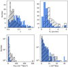 |
Fig. D.2. Distribution of the redshift, core radius, flux, and luminosity for detected and undetected NORAS clusters. The histogram filled with slashed lines is for the detected clusters, while the blue-filled histogram is for the undetected ones. |
Appendix E: Examples
There are 60 clusters with extent > 15′ in our catalog. For some of the detections, the extent might be over-estimated. This mainly comes from the effects of the foreground or background, or the fluctuation of the exposure map. However, this effect can be corrected with the growth curve analysis (Sec. 2.4.1). And the R500 is more accurate to characterize the cluster.
In Fig. E.1, the images of two such clusters are shown as examples. Both of them are with extent > 15′. The left column is RXGCC 296, and the right column is RXGCC 400. RXGCC 296 is a Bronze cluster, and RXGCC 400 is a Silver cluster. In each column, the RASS image, reconstructed X-ray image, DSS image, SDSS images, and the redshift histogram of galaxies are shown in the sequence. As mentioned in Sec. 2.2, the label extent is an indication of the size of detected clusters, which is shown with the red circle in the first two panels of each column.
 |
Fig. E.1. Two RXGCC clusters with extent > 15′. The left column lists images of RXGCC 296 and the right column for RXGCC 400. In every column, the panels show (from top to bottom), the RASS image in [0.5−2.0] keV, reconstructed image with wavelet filtering, DSS image, SDSS image, and the redshift histogram. In the first two rows, the center and radius of red circles indicate the position and extent of the candidate, while green contours are obtained from the reconstructed image indicating the smoothed X-ray emission. The images in the third and fourth rows are with the size of 1° ×1°, which is labeled with the yellow box in the first two rows. The DSS images are overlaid with yellow diamonds and blue circles for galaxies and galaxy clusters with Δz < 0.01, respectively. The radius of blue circles is 1 Mpc. The red cross in the fourth panel labels the position of our candidate. The redshift distribution of galaxies with the offset < 15′ and < 0.5 Mpc is shown in the last row, which is overlaid with the redshift of previous optical and ICM-detected clusters respectively in red and green histograms. The redshift of the candidate is shown in solid black line, while the upper and lower limits of 1σ are shown with black dotted lines. |
Appendix F: Redshift and classification changes in the catalog
In this section, we add comments about the redshift and classification changes for some detections, listed in the Tab. F.1. The automatic result of the redshift and classification are listed in the last two columns (as per the method described in Sec. 2.3.1, Sec. 2.3.2, and Sec. 2.3.3). As discussed in Sec. 2.3.4, the visual check resulted in modifications for some candidates, shown in columns 2 and 3, with the information of multi-wavelength images, spatial distribution, and redshifts of galaxies.
Redshift or classification changes.
All Tables
All Figures
|
Fig. 1. Extent-extension likelihood plane that defines our criteria to select extended X-ray sources (see Paper I for further details). Top panel: RXGCC clusters, i.e., Gold+Silver+Bronze. Top-left, top-right, and bottom-left panels: sub-samples of RXGCC: Gold – new identified clusters; Silver – previous optical/infrared-identified clusters; Bronze – previous ICM-identified clusters. Bottom-right panel: false detections – spurious detections. |
| In the text | |
|
Fig. 2. Redshift distribution for different classes of our cluster candidates. The overlaid vertical line indicates the median redshift of different classes. For simplicity, we use ‘G’, ‘S’, and ‘B’ for short for the Gold, Silver, and Bronze samples. |
| In the text | |
|
Fig. 3. All-sky distributions. Top: RXGCC clusters. Bottom: false detections. |
| In the text | |
|
Fig. 4. Distribution of parameters of the RXGCC sample, the previous ICM-detected sample (Bronze), and the new ICM-detected sample (Gold+Silver), shown as solid, dashed, and dotted histograms and lines, in sequence. We refer to Sect. 2.4.1 for details on the estimation methods. Both the F500 and L500 are the values in [0.1−2.4] keV band. We manually set the upper parameter limit of the axis in the plot, to remove a few outliers with large parameter value in the histogram. |
| In the text | |
|
Fig. 5. Relation between the value of L500, M500, F500, and the integrated cluster numbers with larger luminosity, mass, or flux. Bottom-left panel: the dashed line has a slope of −1.5, normalized to match the value with fX = 2 × 10⁻¹¹ erg s−1 cm−2. The dotted vertical line labels the flux of 5 × 10⁻¹² erg s−1 cm−2. Bottom-right panel: relation between the redshift and L500. The curves for the flux limits of 10−12 and 3 × 10⁻¹² erg s−1 cm−2 are overlapped as dotted curve and dashed curve, respectively. Both the F500 and L500 are the value in [0.1−2.4] keV band. |
| In the text | |
|
Fig. 6. Relation between the R500, Rsig, extent, the integrated count rate within R500, the integrated count rate within Rsig, and the flux inside R500. Top-left, top-right, and bottom-left panels: the red dashed line labels the 1:1 relation, while bottom-right panel: relation of F500 = CRsig × 2 × 10⁻¹¹ (erg s−1 cm−2)/(count s−1). Top-left panel: the red dotted line shows the dividing line to get the very extended candidates discussed in Sect. 4.1. |
| In the text | |
|
Fig. 7. Relation between the β value, the core radius (rc), the significant radius (Rsig), and the total number of photons within the significant radius. The grey dots, and blue empty circles show the “high β” and “low β” samples, respectively, which are divided by the line of β = 2/3. |
| In the text | |
|
Fig. 8. Relation between the β value, the core radius (rc), the significant radius (Rsig), and the total number of photons within the significant radius. In these panels, the grey dots, blue empty circles, and red empty squares represent the Silver+Bronze sample, Faint Gold sample, and Bright Gold sample, respectively. The Bright Gold and Faint Gold samples are divided from the Gold sample by F500 = 3 × 10⁻¹² erg s−1 cm−2. Bottom-right panel: β histogram of the same samples, with colors matching with the other panels. |
| In the text | |
|
Fig. 9. β distribution of the whole RXGCC and the very extended sub-sample. The very extended sub-sample is comprised of clusters located at the bottom-right part of the dividing line in the top-left panel of Fig. 6. |
| In the text | |
|
Fig. 10. Exposure variation of detections. Top panel: RASS-II exposure map (adapted from the Fig. 1 of Voges et al. 1999). Second panel: all-sky distribution of all detections, colors vary with the exposure variation. Third panel: exposure variation distribution for detections in classes, the average value are overlaid with vertical lines. Bottom panel: relation between the false detection ratio with exposure variation. |
| In the text | |
|
Fig. 11. Differences in positions and redshifts between our candidates and position-matched MCXC/PSZ2/REFLEX/NORAS clusters. Top panel: the offset threshold is set as 1°, without setting a redshift limit. Bottom panel: the position offset is set as < 15′. The dotted vertical lines labels out the criteria used in this work. |
| In the text | |
|
Fig. 12. Offset distribution between RXGCC clusters and the nearest RXS source. |
| In the text | |
|
Fig. B.1. Number of detections (shown as black line with labels on the left) and contamination ratio (shown as blue line with labels on the right) varies with the offset threshold in the cross-matching with previously identified clusters (shown in X-axis). The offset has been set to be 0.25, 0.5, 0.75, 1.0 Mpc. The dots in the plot are shifted to the right with a little distance to avoid the overlapping. The detection numbers and contamination ratio for previous ICM-detected clusters (top-left panel), previous optical/infrared clusters (top-right panel), previous optical/infrared clusters not detected in ICM (bottom-left panel), the whole sample of detections (bottom-right panel) are shown. The solid and dashed lines show the results when the upper limit of galaxy redshift is set to be 0.3 and 0.4, respectively. To estimate the redshift of detections, we consider three different situations. Firstly, we only take spectroscopic galaxy redshift into account (shown with thin lines). Secondly, we consider the spectroscopic galaxy redshift and photometric one separately (shown with lines in the normal width). Lastly, we combine the spectroscopic galaxy redshifts and photometric ones together without distinguishing them (shown with thick lines). |
| In the text | |
|
Fig. C.1. Comparison of spatial distribution (left panels) and redshift distribution (right panels) of detected and undetected MCXC, PSZ2 and Abell clusters, from the top to the bottom panels. |
| In the text | |
|
Fig. D.1. Distribution of the redshift, significant radius, flux, and luminosity for detected and undetected REFLEX clusters. The histogram filled with slashed lines is for the detected clusters, while the blue-filled histogram is for the undetected ones. |
| In the text | |
|
Fig. D.2. Distribution of the redshift, core radius, flux, and luminosity for detected and undetected NORAS clusters. The histogram filled with slashed lines is for the detected clusters, while the blue-filled histogram is for the undetected ones. |
| In the text | |
|
Fig. E.1. Two RXGCC clusters with extent > 15′. The left column lists images of RXGCC 296 and the right column for RXGCC 400. In every column, the panels show (from top to bottom), the RASS image in [0.5−2.0] keV, reconstructed image with wavelet filtering, DSS image, SDSS image, and the redshift histogram. In the first two rows, the center and radius of red circles indicate the position and extent of the candidate, while green contours are obtained from the reconstructed image indicating the smoothed X-ray emission. The images in the third and fourth rows are with the size of 1° ×1°, which is labeled with the yellow box in the first two rows. The DSS images are overlaid with yellow diamonds and blue circles for galaxies and galaxy clusters with Δz < 0.01, respectively. The radius of blue circles is 1 Mpc. The red cross in the fourth panel labels the position of our candidate. The redshift distribution of galaxies with the offset < 15′ and < 0.5 Mpc is shown in the last row, which is overlaid with the redshift of previous optical and ICM-detected clusters respectively in red and green histograms. The redshift of the candidate is shown in solid black line, while the upper and lower limits of 1σ are shown with black dotted lines. |
| In the text | |
Current usage metrics show cumulative count of Article Views (full-text article views including HTML views, PDF and ePub downloads, according to the available data) and Abstracts Views on Vision4Press platform.
Data correspond to usage on the plateform after 2015. The current usage metrics is available 48-96 hours after online publication and is updated daily on week days.
Initial download of the metrics may take a while.