| Issue |
A&A
Volume 619, November 2018
|
|
|---|---|---|
| Article Number | A107 | |
| Number of page(s) | 25 | |
| Section | Interstellar and circumstellar matter | |
| DOI | https://doi.org/10.1051/0004-6361/201833573 | |
| Published online | 13 November 2018 | |
Protostellar Outflows at the EarliesT Stages (POETS)
I. Radio thermal jets at high resolution nearby H2O maser sources★
1
Max-Planck-Institut für Radioastronomie,
Auf dem Hügel 69,
53121
Bonn,
Germany
e-mail: This email address is being protected from spambots. You need JavaScript enabled to view it.
2
INAF,
Osservatorio Astronomico di Cagliari,
via della Scienza 5,
09047
Selargius,
Italy
3
INAF, Osservatorio Astrofisico di Arcetri,
Largo E. Fermi 5,
50125
Firenze,
Italy
4
Department of Astrophysics/IMAPP, Radboud University Nijmegen,
PO Box 9010,
6500
GL Nijmegen,
the Netherlands
Received:
5
June
2018
Accepted:
16
July
2018
Abstract
Context. Weak and compact radio continuum and H2O masers are preferred tracers of the outflow activity nearby very young stars.
Aims. We want to image the centimeter free–free continuum emission in the range 1–7 cm (26–4 GHz), which arises in the inner few 1000 au from those young stars also associated with bright H2O masers. We seek to study the radio continuum properties in combination with the H2O maser kinematics to quantify the outflow energetics powered by single young stars.
Methods. We made use of the Karl G. Jansky Very Large Array (VLA) in the B configuration at K band and the A configuration at both Ku and C bands in order to image the radio continuum emission toward 25 H2O maser sites with an angular resolution and thermal rms on the order of 0.′′1 and 10 μJy beam−1, respectively. These targets add to our pilot study of 11 maser sites previously presented. The sample of H2O maser sites was selected among those regions that have accurate distance measurements, obtained through maser trigonometric parallaxes, and H2O maser luminosities in excess of 10−6 L⊙.
Results. We present high-resolution radio continuum images of 33 sources belonging to 25 star-forming regions. In each region, we detect radio continuum emission within a few 1000 au of the H2O masers’ position; 50% of the radio continuum sources are associated with bolometric luminosities exceeding 5 × 10³ L⊙, including W33A and G240.32 + 0.07. We provide a detailed spectral index analysis for each radio continuum source, based on the integrated fluxes at each frequency, and produce spectral index maps with the multifrequency synthesis deconvolution algorithm of CASA. The radio continuum emission traces thermal bremsstrahlung in (proto)stellar winds and jets that have flux densities at 22 GHz below 3 mJy and spectral index values between − 0.1 and 1.3. We prove a strong correlation (r > 0.8) between the radio continuum luminosity (Lrad) and the H2O maser luminosity (LH2O) of (L8 GHz∕mJy kpc2) = 103.8 × (LH2O L⊙)0.74. This power-law relation is similar to that between the radio continuum and bolometric luminosities, which confirms earlier studies. Since H2O masers are excited through shocks driven by (proto)stellar winds and jets, these results provide support to the idea that the radio continuum emission around young stars is dominated by shock ionization, and this holds over several orders of magnitude of stellar luminosites (1–105 L⊙).
Key words: stars: formation / radio continuum: ISM / HII regions / ISM: jets and outflows / techniques: high angular resolution
The reduced continuum maps are only available at the CDS via anonymous ftp to cdsarc.u-strasbg.fr (130.79.128.5) or via http://cdsarc.u-strasbg.fr/viz-bin/qcat?J/A+A/619/107
© ESO 2018
1 Introduction
Outflow activity is a proxy for ongoing star formation. A number of outflow studies have established a correlation between the bolometric luminosity (Lbol) of a star-forming region and the integrated (molecular) outflow properties. These properties include the mechanical force and momentum released into the ambient gas, which, at parsec scales, quantify the overall contribution of an ensemble of outflows (e.g., Arce et al. 2007; Frank et al. 2014, and references therein). This relationship holds over six orders of magnitude of Lbol (e.g., Beuther et al. 2002, their Fig. 4; Maud et al. 2015, their Fig. 7) and is interpreted as evidence for a single outflow mechanism, which scaleswith the stellar luminosity, and the motion of the outflows being momentum driven. However, on scales of a few 1000 au, representative of individual young stars, there are poor statistics on outflow properties for stellar luminosities exceeding 103 L⊙.
For the purpose of studying the dynamical properties of the outflow emission in the vicinity of luminous young stars, we started the Protostellar Outflows at the EarliesT Stages (POETS) survey. The target sample has been selected with the idea of combining the kinematic information of outflowing gas, inferred from the H2O maser emission, with the information of ejected mass, inferred from the H II, free–free continuum emission (e.g., Moscadelli et al. 2016; Sanna et al. 2016).
On the one hand, H2O maser emission traces shocked gas propagating in dense regions (nH_2 > 106 cm−3) at velocities between 10 and 200 km s−1 (e.g., Hollenbach et al. 2013): these properties make H2O masers signposts of (proto)stellar outflows within a few 1000 au from their driving source. Maser spots, namely, cloudlets on the order of a few au in size, are ideal test particles to measure the local three-dimensional motion of gas shocked where stellar winds and jets impact ambient gas (e.g., Torrelles et al. 2003; Goddi et al. 2006; Sanna et al. 2012; Moscadelli et al. 2013; Burns et al. 2016; Hunter et al. 2018).
On the other hand, thermal (bremsstrahlung) continuum emission, with flux densities lower than a few mJy, and spectral index values (α) at centimeter wavelengths between − 0.1 and below 2 trace the ionized gas component of stellar winds and jets (Panagia & Felli 1975; Reynolds 1986; Anglada 1996; Anglada et al. 1998). Ionization is caused by shocks around young stars with spectral types later than B, which emit negligible Lyman flux (Curiel et al. 1987, 1989). In these sources, the centimeter continuum luminosity scales with the stellar luminosity as a power law of approximately index 0.6 (Anglada 1995; Anglada et al. 2015). Extrapolating this law to young stars of spectral types B and earlier, for instance, a continuum flux of approximately 1 mJy at 8 GHz is expected for a B1 zero-age main sequence (ZAMS) star at a distance of 1 kpc from the Sun. For comparison, a homogeneous, optically thin H II region, that is excited by the Lyman photons of a B1 ZAMS star, emits a continuum flux more than two orders of magnitude higher (≈ 0.2 Jy) at the same frequency and distance. It follows that, ionized stellar winds and jets can be detected prior to the ultra-compact (UC) H II region phase, which implies typical lifetimes older than 104 yr (e.g., Churchwell 1999, 2002; Hoare et al. 2007).
Recently, two distinct surveys have searched for ionized stellar winds and jets in regions with bolometric luminosities typically exceeding 103 L⊙ (Rosero et al. 2016; Purser et al. 2016). Rosero et al. (2016) made use of the Karl G. Jansky Very Large Array (VLA) at 6 and 22 GHz to survey 58 star-forming regions at different stages of evolution. They detected ionized jet emission in about half the sample with typical values of angular resolution and sensitivity of 0.4–0.3 arcsec and 5–10 μJy beam−1, respectively. Purser et al. (2016) made use of the Australia Telescope Compact Array (ATCA) at 5, 9, 17, and 22 GHz to survey 49 star-forming regions selected from the RMS survey. They detected ionized jet emission in 26 distinct sites (12 of which are candidates) with typical values of angular resolution and sensitivity ranging between 2–0.5 arcsec and 17–106 μJy beam−1, respectively. In particular, Purser et al. (2016) reported nonthermal knots in a subset of jets (10), which resemble the prototypical magnetized jet in HH 80–81 (Carrasco-González et al. 2010; Rodríguez-Kamenetzky et al. 2017).
In order to provide a homogeneous sample of stars at an early stage of evolution, we limited the sample to rich H2O maser sites not associated with UCH II regions (where the continuum emission exceeds 10 000 au in size). Among the H2O maser sites satisfying this requirement, we selected those targets whose distances were accurately determined by trigonometric parallax measurements, and where the maser positions are known at milli-arcsecond resolution (Reid et al. 2014). The POETS sample of 36 distinct fields, listed in Table 1, was surveyed with the VLA at 6, 15, and 22 GHz in the A- and B-array configurations. In Moscadelli et al. (2016), we presented a pilot study of 11 targets belonging to the POETS survey (hereafter, Paper I). More details about the target selection can be found in Paper I. In this work, we present the full sample of radio continuum sources; a following paper will combine continuum and maser information.
In Sects. 2 and 3, we summarize the observation information and explain the details of the data analysis, respectively. In Sect. 4, we present and discuss the overall results of the radio continuum survey. Conclusions are drawn in Sect. 5.
Target fields of the POETS survey.
2 Observations and calibration
We conducted VLA1 observations, under program 14A-133, at C, Ku, and K bands toward 26 distinct Galactic fields associated with strong H2O maser emission (Table 1). Toward each field, we observed with the A-array configuration at C and Ku bands and with the B-array configuration at K band in the periods March–May 2014 and February–March 2015, respectively.
For high-sensitivity continuum observations in the C, Ku, and K bands, we employed the 3-bit samplers observing dual polarization over the largest receiver bandwidth of 4, 6, and 8 GHz, respectively.At each band, we made use of the wideband setup, tuning 2, 3, and 4 2-GHz wide IF pairs across the receiver bandwidth. Each IF comprised 16, 128-MHz wide sub-bands with a channel spacing of 1 MHz. At C and K bands, we also used a narrow spectral unit of 4 MHz centered on the 6.7 GHz methanol and 22 GHz water maser lines. These bands had widths of 180 and 54 km s−1 to cover the respective maser emission. In addition, the bands were correlated with 1664 and 128 channels to achieve sufficient velocity resolutions of 0.1 and 0.4 km s−1 to spectrally resolve single maser lines. In the following, we report on the radio continuum data.
Our previous pilot observations, conducted under program 12B-044 (Moscadelli et al. 2016), have demonstrated that the free–free continuum emission, associated with the H2O masers, has peak flux densities of a few 100 μJy at centimeter wavelengths on average. Therefore, we integrated on each source for 10–20 min to achieve a thermal rms noise on the order of 10 μJy beam−1, and a signal-to-noise ratio (S/N) typically in excess of 10. More details on the observational strategy can be found in Sec. 3.1 of Moscadelli et al. (2016). Observation information is summarized in Table 2.
Data reduction was performed within the Common Astronomy Software Applications package (CASA), making use of the VLA pipeline. Radio fluxes were calibrated with the Perley–Butler 2013 flux density scale. Additionally, we flagged each dataset based on the quality of both the amplitude and phase calibration and performed self-calibration on those radio continuum maps which were limited in dynamic range (10 <S/N < 50), corresponding to source fluxes greater than a few 100 μJy.
Summary of VLA observations (code 14A-133).
3 Method
For each field, in Figs. 1–4 and A.2 we present the radio continuum maps in the C, Ku, and K bands and analyze the radio spectral index of the continuum emission following two methods: by integrating the radio fluxes at each band and fitting the spectral slope among the bands (Sect. 3.2); and by comparing the radio emission among the bands in the uv plane directly (Sect. 3.3), making use of the multifrequency synthesis (MFS) deconvolution of the task clean of CASA (Rau & Cornwell 2011). In the following, we provide the details of our analysis.
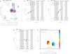 |
Fig. 1 Example of stellar wind emission from a double system: H2O maser site G229.57+0.15 (Sect. 4.1). Panela: superposition of the VLA maps for the C- (grayscale/black contours), Ku- (red), and K-band (blue) emission (Sect. 3.1). Contour levels, at multiples of the 1σ rms, are indicated in the footnote. Synthesized beams for each band are shown in the bottom left corner. A scale bar in units of au is drawn near the bottom axis. Three distinct continuum sources are identified and labeled VLA–1, VLA–2, and VLA–3 from the brightest to the faintest. Panelsb–d: spectral energy distribution for the three sources identified in panela separately (Sect. 3.2). Each plot shows the logarithm of the integrated flux (in mJy) as a function of the logarithm of the observed frequency (in Hz). Various frequency bands are labeled near the bottom axis together with the reference wavelength; gray shades indicate the boundary of each band. For each band combination, the linear spectral index value (α) and its uncertainty are specified in the upper left corner. The common range of uv distances (e.g., 40–800 kλ in panelb and full uv range in panel d) used to compute the integrated fluxes among the bands is indicated in the upper right. Panele: color map of the linear spectral index (α) computed with the MFS algorithm of the task clean of CASA (Sect. 3.3). Frequency bands used to fit the spectralindex are listed on top; spectral index values are quantified by the right-hand wedge. The uncertainty on α is indicated in the wedge label; this value is an upper limit that holds at the 7σ contour of the average brightness map (black contours). Contour levels of the average brightness map, at multiples of the 1σ rms, are indicated in the footnote; the central frequency (ν0) of the average brightness map is specified in the legend. The absolute coordinates of (0,0) offset are indicated in the footnote (see Table 1). Radio continuum components and the scale bar as in panela. |
3.1 Continuum maps
At variance with our pilot program 12B-044 (Paper I), we observed at K band with the B-array configuration instead of the A-array, so that the C- and K-band observationsare sensitive to the same angular scales, covering a common range of spatial frequencies (< 900 kλ). The observations at Ku band cover greater uv distances in excess of 2000 kλ. Continuum maps are shown in the left panels of Figs. 1–4 and A.2 for each frequency band. We describe the imaging techniques in the following:
Beam and weighting. Each field was imaged with the task clean of CASA interactively and with a circular restoring beam (Col. 4 of Table A.1). The restoring beam size was set equal to the geometrical average of the major and minor axes of the clean beam size. The pixel size is a factor 0.2–0.25 of the half-power beam width (HPBW). By rule of thumb, the C- and K-band maps were produced with a common Briggs robustness parameter of 0.5, to simultaneously optimize side-lobes suppression and sensitivity; the Ku-band maps were produced with natural weightings to enhance the sensitivity in the shortest baselines. For faint sources with peak brightness below 7σ, we applied natural weightings without distinction. The beam size ranges from a minimum of 0.′′ 110 at Ku band to a maximum of 0.′′481 at C band.
UV range. At the bottom of each plot, we indicate with “UVCUT” or “TAPER” whether a lower limit to the uv range or tapering were used for cleaning, respectively. At each frequency, the targets in our sample are more compact than the largest angular size (θLAS), which can be imaged with the A- and B-array configurations (Table 2). On the other hand, five fields in our sample exhibit extended bright continuum emission (other than the targets) that cannot be recovered without shorter baselines. Since this emission adds to the image residuals and limits image sensitivity, we cleaned those fields by setting a lower cut to the uv plane. A lower cut of 100 kλ corresponds to filter out emission more extended than 2″. Details are given in the footnotes to Table A.1.
Field of view. In Figs. 1–4 and A.2, we limited the field of view so as to include the radio continuum sources closest to the H2O maser emission detected in the field. For the brightest maser spots (≳0.5 Jy beam−1), absolute positions can be obtained from the Bar and Spiral Structure Legacy (BeSSeL) website2 (Reid et al. 2014). In each plot, we draw a scale bar to quantify the linear size of the field; the linear size is computed from the distance values reported in Table 1 of Paper I. Fields of view range from a minimum of 650 au (Fig. 2) to a maximum of 9000 au (Fig. 1).
For each field, we superpose, where available, the C-band emission in black contours (and gray tones), the Ku-band emission in red contours, and the K-band emission in blue contours. Map contours are listed at the bottom of each plot and are scaled at multiples of the 1σ rms (Col. 5 of Table A.1). The rms noise was estimated with the task imstat of CASA across a region without continuum emission. Alternatively, we indicate whether the field was not observed at a given frequency band or the emission was not detected above a 3–5σ level.
When multiple radio continuum peaks exceeding 5σ are detected(e.g., Fig. 1), individual peaks are labeled with numbers increasing with decreasing brightness. For each peak, or component, in Table A.1, we report the maximum pixel position (Cols. 6–7), the maximum pixel value (Col. 8), and the integrated flux (Col. 10) obtained with the task imstat of CASA. Values of integrated flux are measured in images produced with a common uv coverage among the bands (see Sect. 3.2). The flux density of single components was computed within the 3σ contour at each band. Blended sources were detected in two fields (Figs. 1 and 3) and their flux densities were computed within squared boxes centered on each peak.
In Col. 9of Table A.1, we assign a grade to each source depending on the compactness of the emission. We fitted the continuum emission within the 3σ contour with a two-dimensional (elliptical) Gaussian (task imfit of CASA) and classified the source size as follows: the source is compact (“C”) if its deconvolved size is smaller than half the beam size; the source is slightly resolved (“SR”) if its deconvolved size is smaller than the beam and larger than half the beam size; and the source is resolved (“R”) if its deconvolved size is larger than the beam size.
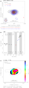 |
Fig. 2 Example of optically thin thermal jet emission: H2O maser site G090.21+2.32 (Sect. 4.2). Labels and symbols as in Fig. 1. Panelb: we divided the C and K bands in twosub-bands to show that the spectral index within each band is consistent with the spectral index interpolated to the Ku-band frequency. The SED shows a region of optically thin (resolved) emission below 15 GHz and a region of optically thick (compact) emission above 15 GHz. The spectral index map of panelc was computed within the (linear) range of optically thin emission (C and Ku bands only). |
3.2 Spectral energy distributions
In Figs. 1–4 and A.2, we show the results of the spectral index analysis based on the integrated fluxes at each band (SED) under the assumption that  =
= . As a caveat to the spectral index analysis, we assume there was no significant source variability during the one-year interval between the A- and B-array configurations. Similar to Paper I, we measure the continuum spectral index following four steps:
- 1.
First, we constrain a common uv range among the radio bands of 40–800 kλ and imaged each band separately with the same round beam (0.′′30) and pixel size (0.′′06). Higher values of the minimum uv distance were used for four fields (see Sect. 3.1). On top of each plot, we specify the range of uv distances selected for a given field.
- 2.
These maps were used to select a polygon around the source that encloses the continuum emission; these polygons typically correspond to the 3σ contours. For instance, sources detected at C, Ku, and K bands define three distinct polygons. At a given frequency, we estimate the integrated flux as the averaged flux over the three polygons. The uncertainty of the averaged flux is estimated as the dispersion of the mean and summed in quadrature with a 10% error in the absolute flux scale. This method takes into account that, owing to small position shifts among the C-, Ku-, and K-band maps (≤0.′′1), the same polygon does not trace the same region at different frequencies.
- 3.
We use the averaged fluxes and their uncertainties to compute the continuum spectral index with a linear regression fit, where log10(Sν) = α × log10(ν) + const. For sources only detected at K band, we provide a lower limit to the spectral index by fitting a straight line to the K-band flux and the upper limit of the Ku-band flux.
- 4.
We plot the averaged fluxes at the C, Ku, and K bands (Fig. 1–4 and A.2); each frequency is identified with the same color used for the continuum maps. In each plot, we draw the spectral index values (and uncertainties) of the various band combinations and the spectral index among the three bands where available.
In Col. 11 of Table A.1, the best-fitting value of the spectral index is given for each source.
3.3 Spectral index maps
In Figs. 1–4 and A.2, we provide an alternative analysis of the continuum spectral index based on the MFS cleaning (Rau & Cornwell 2011, and references therein) under the assumption that  =
= . The task clean of CASA was run with parameter nterm = 2, which expands the observed brightness distribution taking into account the first two terms of a Taylor series, i.e.,
  . This procedure produces a set of Taylor-coefficient images (Sects. 2.2 and 2.7 of Rau & Cornwell 2011). The first coefficient of the Taylor expansion defines the average brightness distribution (in CASA, map extension “.tt0”); the spectralindex map is derived from the second coefficient (in CASA, map extension “.alpha”), which is the product of the average brightness times the local spectral index value. The MFS algorithm compares observed and modeled visibilities in the uv plane, providing information on the spatial distribution of the spectral index value, as opposed to the average spectral index inferred in Sect. 3.2. Hereafter, we refer to the this method as the “α-map”.
Since the accuracy of the spectral index calculation depends on the S/N of the brightness distribution, the following constraints apply: first, the α-maps were only processed for those sources where the continuum emission exceeds 7σ at each band. Second, the α-maps are only shown where the following two conditions hold: the average map exceeds 7σ and the uncertainty of α estimated by the algorithm is less than 0.2–0.3 (map extension “.alpha.error”).
For each source that satisfies the first requirement, we cleaned the datasets available all together with a Briggs robustness parameter of 0.5. In Figs. 1–4 and A.2, each α-map shows the average brightness map in contours and the spectral index map in colors, according to the right-hand wedge. In each plot, we also specify the center frequency of the average brightness map and the uncertainty on α, which increases from the brightness peak, where typically Δα < 0.1, to the outer iso-contour, where Δα = 0.2 or 0.3.
In Appendix A, we show that small position shifts, between maps at multiple frequency bands, produce systematic variations in the spectral index maps. Since these position shifts are of the same order of the calibration uncertainties, it is necessary to exert caution when interpreting spectral index gradients.
4 Results and discussion
In this section, we firstly discuss the details of four examples of radio continuum emission (Figs. 1–4), which provide the background to interpret the entire sample of sources (Fig. A.2). We then comment on the nature of the radio continuum emission by comparing the radio luminosity of our sample with both the H2O maser and bolometric luminosities.
In the following, if the radio continuum SED is well reproduced with a linear spectral slope, we use the terms (ionized) “stellar wind” and “thermal jet” to distinguish between unresolved and resolved and elongated emission, respectively. In Col. 12 of Table A.1, we provide a classification for the entire sample of sources, which are divided as follows: 15 stellar winds, 8 thermal jets, 2 H II regions, and 7 sources detected at one frequency only (and not classified).
4.1 Example 1: compact stellar winds from a double system
In Fig. 1, we present an example of stellar wind sources toward the H2O maser site G229.57+0.15. In panel a, we plot the brightness distribution of the continuum emission detected in the three observed bands. These maps show two compact sources, labeled VLA–1 and VLA–2, which are aligned along the east-west direction, and a region of extended (resolved) emission, labeled VLA–3, which extends northward of VLA–1 and VLA–2. The radio continuum peaks of VLA–1 and VLA–2 are separated by about 2800 au (Table A.1). These maps were produced with natural weightings to retrieve the extended flux associated with VLA–3 and have approximately the same rms noise of 5–7 μJy beam−1.
Radio continuum components VLA–1 and VLA–2 have comparable brightnesses at K band of 170 μJy beam−1, but the peakof VLA–2 is about half that of VLA–1 at C band (Table A.1). This difference determines a much steeper gradient in the SED of VLA–2 with respect to that of VLA–1, which is evident by comparing panels b and c of Fig. 1. In both panels, the integrated fluxes computed at each frequency are strictly aligned and define a linear gradient (α) between the C, Ku, and K bands of 0.68 ± 0.02 and 1.2 ± 0.1 for the VLA–1 and VLA–2 sources, respectively. The higher flux uncertainties of VLA–2, with respect to VLA–1, are due to the larger difference between the fluxes integrated within the C-, Ku-, and K-band boxes. These boxes coincide with the 3σ contours everywhere except between VLA–1 and VLA–2, where we drew a clear cut along the north-south direction to separate the emission. The spectral index values of VLA–1 and VLA–2 are consistent with the radio continuum emission being produced by thermal bremsstrahlung from a stellar wind.
At variance with sources VLA–1 and VLA–2, source VLA–3 is resolved out at the Ku band, and, to derive the continuum spectral index in this region, we only made use of the C and K bands (panel d). Since the C and K bands observations are sensitive to the same spatial scales, we did not limit the uv range to compute the integrated fluxes and used a squared box that encloses the emission between a declination of –14:41:32.03 and –14:41:31.17. The spectral index value of VLA–3 is of 0.0 ± 0.1, and, taking into account the spatial morphology of the radio continuum emission, it is consistent with thermal bremsstrahlung from an optically thin radio jet. This emission might be associated either with VLA–1 or VLA–2.
In panel e, we plot the spectral index map determined from the combination of the C-, Ku-, and K-band datasets; this map is referred to the central frequency of the Ku band (15 GHz). Only sources VLA–1 and VLA–2 have sufficiently high S/N (> 7σ) to compute the spectral index in the uv domain with high accuracy. The color scale of panel e shows that the spectral index of VLA–1 ranges from 0.65 to 0.95, encompassing the average value determined in panel b. The extremes of the alpha range coincide with the 7σ contour of the average brightness map (black contours), where the uncertainty on α increases to ± 0.2. Similarly, the spectral index map of VLA–2 converges, toward the brightness peak, on the average value determined in panel c; the spectral index varies over an interval 1.0–1.3 of about 1σ.
Notably, sources VLA–1 and VLA–2 make the case for two nearby (unresolved) stellar winds with sharply different spectral indexes. Following Reynolds (1986), the higher spectral index value of VLA–2 may be interpreted as the radio continuum opacity changing more rapidly in VLA–2 than in VLA–1. We make use of Eq. (15) of Reynolds (1986), which quantifies the spectral index of a radio jet as a function of its geometry (ϵ), temperature (qT), and optical depth (qτ) variations across the flow. We assume that the two flows are either spherical or conical (ϵ = 1), and since both sources are unresolved at the beam scale, we take an upper limit to the source size of 0.′′ 206 at K band, corresponding to 930 au at a distance of 4.52 kpc. We also assume that the ionized gas is approximately isothermal within a radius of 500 au from the central source (qT = 0). Under these conditions, Eq. (15) of Reynolds (1986) predicts that (α1 –α2)∕4.2 = –
–  = – 0.12, where
  and
and  are negative parameters and the subscripts 1 and 2 are relative to sources VLA–1 and VLA–2, respectively. This calculation implies that the absolute value of q
 is smaller than that of q
 .
.
4.2 Example 2: optically thin thermal jet emission and opaque core
In Fig. 2, we present an example of a radio thermal jet source toward the H2O maser site G090.21+2.32. This source has the lowest bolometric luminosity in our sample (27 L⊙). The radio continuum maps show that the emission is elongated in the east-west direction (panel a). At the C and Ku bands (4–18 GHz), the continuum emission is resolved at a scale of 0.′′292 and 0.′′ 166, respectively; at the K band (18–26 GHz), the continuum emission has a deconvolved size on the order of half the beam (0.′′ 140). At a distance of 670 pc, the source size corresponds to about 90 au in the higher frequency range and exceeds 200 au in the lower frequency range.
The flux density at C band is comparable to that at the Ku band, which is almost three times less than the flux recovered at K band (Table A.1). To verify that the difference between the Ku- and K-band fluxes does not depend on the calibration, we divided both the C and K bands in two sub-bands, each one equal to half the bandwidth, and imaged each sub-band separately. The integrated fluxes derived from each sub-band are plotted in panel b of Fig. 2. In this plot, we show that the spectral index fitted between the C and Ku bands reproduces the spectral slope determined within the C band only; similarly, the spectral slope within the K band only is consistent with that between the Ku and K bands. The spectral index values derived between the C and Ku bands (− 0.1± 0.1), and between the Ku and K bands (2.5 ± 0.5) are consistent, respectively, with thermal jet emission that is optically thin for frequencies below 15 GHz, and with a compact core that is optically thick for frequencies above 15 GHz. This scenario closely resembles that predicted by Reynolds (1986, e.g., their Fig. 2).
In panel c, we plot the spectral index map determined from the combination of the C- and Ku-band datasets; this map refers to the central frequency between the C and Ku bands (10 GHz). The spectral index map ranges from − 0.2 to 0.3; at these extremes, corresponding to the outer iso-contours, the uncertainty increases to ± 0.2 and decreases below ± 0.1 at the brightness peak. This range of spectral index values is consistent with the average spectral index derived in panel b within 1σ. Spectral index variations observed in panel c are likely an effect of the MFS deconvolution algorithm, produced by combining different Gaussian distributions at distinct frequency bands (see Appendix A).
4.3 Example 3: a thermal jet near a HCH II region
In Fig. 3, we present an example of thermal jet near a hyper-compact (HC) H II region toward the H2O maser site G240.32+0.07. In panel a, the radio continuum emission is dominated by two components, labeled VLA–1 and VLA–2, which are separated by about 4300 au along the northeast-southwest direction. The peak brightness of component VLA–1 is more than ten times higher than that of VLA–2 at each frequency, and both components have a size comparable to that of the beam (Table A.1). Because of the limited uv coverage, we performed self-calibration at each band to improve on the dynamic range of the maps, which exceeds a factor of 100. At Ku band, two additional peaks are distinctly resolved to the northeast and southwest of VLA–1 and VLA–2, respectively, and are labeled VLA–3 and VLA–4. Component VLA–3 is about 50 times less intense than VLA–1, and VLA–4 is about six times less intense than VLA–2 (Table A.1). Because of the larger beam size, at the C and K bands VLA–3 and VLA–4 are heavily blended with, respectively, VLA–1 and VLA–2, and we do not discuss these further3.
In panel b, we show that the integrated fluxes of source VLA–1 do not fit a straight line with positive slope, but can be reproduced by a model of homogeneous H II region with constant density and temperature. We fix the electron temperature of the H II region to 104 K, taking into account the lower limit to the brightness temperature of 3000 K at Ku band (optically thin regime). The continuum spectrum in panel b is produced by a number of Lyman photons (NLy) of 3 × 1046 s−1 and Strömgren radius (RS) of 870 au, corresponding to an angular size of 0.′′370 at a distance of 4.72 kpc (i.e., the beam size). The H II region has an electron density (ne) of 1.2 × 105 cm−3 and emission measure (EM) of 1.2 × 10⁸ pc cm−6. The radio continuum emission is strong enough to allow us to obtain individual spectral index maps of the C and Ku bands separately (panels d and e). These maps show that the spectral index values within the C and Ku bands are in excellent agreement with the continuum spectrum of the H II region, confirming that the spectral slope is inverted between 4 and 18 GHz from positive to negative values. The number of Lyman photons required to excite the HCH II region corresponds to that emitted by a ZAMS star of spectral type between B1–B0.5 (e.g., Thompson 1984). This star dominates the bolometric luminosity of the region of 103.9 L⊙ (Table 1 of Paper I).
In panel c, we show that the integrated fluxes of source VLA–2 fit a straight line with angular coefficient (α) of 0.84; this averaged spectral index is constrained within a small uncertainty of ± 0.03. The radio continuum emission from VLA–2 is consistent with thermal bremsstrahlung from a radio jet, which is elongated in the southeast-northwest direction. On the other hand, the spectral index maps of the C and Ku bands encompass a wide range of (positive) spectral index values. At C band (panel d), α ranges between 1.0 and 1.3; this range is consistent with a single value within 1σ. At Ku band (panel e), α ranges between 0 and 1.5; this range exceeds the largest uncertainty on α (± 0.2) and increases regularly from the southeast to the northwest.
According to Eq. (15) of Reynolds (1986), changes of α with position might be due to changes of the flow geometry (ϵ) and irregular changes of the temperature (qT) and optical depth (qτ) across the flow. Practical examples are a wide-angle wind that collimates at large radii from the star, a sudden drop of temperature away from the heating source, and the optical depth, which increases toward the receding (redshifted) lobe of the outflow and decreases toward the approaching (blueshifted) lobe. The first two examples would produce a symmetric gradient with respect to the central source on the α-map, whereas the third example would produce a continuous change of α across the flow from the redshifted lobe (higher α) to the blueshifted lobe (lower α).
Assuming that the source exciting VLA–2 is at the center of the radio continuum emission, a change in the optical depth between the redshifted jet lobe (to the northwest) and the blueshifted jet lobe (to the southeast) would explain the regular gradient of α. This interpretation is consistent with the geometry of the molecular outflow detected in the region by Qiu et al. (2009). In Appendix A, we generally comment on the variations observed in the spectral index maps.
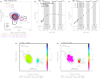 |
Fig. 3 Example of radio thermal jet (VLA–2) near a HCH II region (VLA–1): H2O maser site G240.32+0.07 (Sect. 4.3). Labels and symbols as in Fig. 1. The SED of source VLA–1 was fitted with a model of homogeneous H II region (panelb) with Strömgren radius of 870 au and number of Lyman photons of 3 × 1046 s−1. This model accurately reproduces the observed fluxes at each band. Thanks to the high S/N, in panels d and e we can determine the spectral index maps of the C and Ku bands separately with an uncertainty better than ±0.2. The average brightness map (contours) is that of the Ku band in both panels d and e, for comparison. The spectral index maps trace the turnover of the continuum spectrum for source VLA–1 from α = 1.0–6.0 between 4 and 8 GHz (paneld) to α = –0.1 above 15 GHz (panele). |
4.4 Example 4: a thermal jet with nearby knot – W33A
As a last example, we describe the case of W33A for which X-, Ku-, and Q-band data are available from the literature. We targeted this field at both C and K bands; C-band observationswere conducted under program 12B-044 and are described in Paper I. We detected two radio continuum components (Fig. 4 a), labeled VLA–1 and VLA–2, which are separated by about 3300 au along the northwest-southeast direction. Source VLA–1 coincides in position with the brightest peak of the main dust condensation MM1 (e.g., Fig. 1 of Galván-Madrid et al. 2010), and was previously detected at 3.6 cm, 2 cm, and 7 mm by Rengarajan & Ho (1996) and van der Tak & Menten (2005). Source VLA–2, which is an order of magnitude less bright than VLA–1 at 1 cm, has never been detected before and does not coincide with millimeter dust emission (e.g., Fig. 1 of Galván-Madrid et al. 2010, and Fig. 1 of Maud et al. 2017).
In panelb, we make use of data from the literature to show that the flux density of source VLA–1 exhibits a steady increase over a wide interval of frequencies from 4 to 43 GHz. Since we did not observe this field at Ku band, we divided the K-band data in two sub-bands, each one equal to half the bandwidth to prove that the spectral slope between the C and K bands is preserved within the K band itself. The C-band integrated flux and the two K-band integrated fluxes fit a linear spectral slope of 1.26 ± 0.06, which is consistent with thermal bremsstrahlung emission from a stellar wind or jet. The spectral index of source VLA–1 is higher than 1 to 5σ confidence: this result points to acceleration or recombination in the flow, according to Reynolds (1986). In panel b, we also plot the flux densities measured at X (0.79 mJy) and Ku (1.86 mJy) bands from Table 2 of Rengarajan & Ho (1996), and the Q-band flux density (4.3 mJy) from Table 1 of van der Tak & Menten (2005). We account for a 20% uncertainty of the absolute flux scale at X, Ku, and Q bands; these observations were conducted on April 1990, February 1984, and September 2001, respectively.
In panel c, we show that the spectral index of radio component VLA–2 (− 0.12 ± 0.08) is that of optically thin continuum emission. For the spectral index analysis, the K-band data were split into two sub-bands as in panel b. Radio thermal jet emission is expected to become totally transparent (S ∝ν−0.1) away from the driving source (Reynolds 1986). Combining this information with the spatial information of the outflow emission from MM1-main, we interpret source VLA–2 as a knot of the radio jet. The near-infrared and molecular outflow emission driven by MM1-main is elongated at a position angle (east of north) between 133° and 145° (de Wit et al. 2010; Davies et al. 2010; Galván-Madrid et al. 2010). Accordingly, radio components VLA–1 and VLA–2 are aligned along a position angle of 152° measured between the K-band peaks.
 |
Fig. 4 Example of radio thermal jet (VLA–1) with nearby knot (VLA–2): H2O maser site G012.91−0.26 or W33A (Sect. 4.4). Labels and symbols as in Fig. 1. Two radio continuum sources are detected at both C and K bands along a position angle of approximately 152° (panel a): the brightest emission coincides in position with the brightest millimeter source in the dusty core MM1. Panelsb and c: we fitted the spectral index of sources VLA–1 and VLA–2 with the measured fluxes at C and K bands, after dividing the K-band observations into two sub-bands, each spanning 4 GHz. Panelb: fluxes reported in the literature at X (pink), Ku (red), and Q (cyan) bands are consistent with a single linear slope, i.e., from 4 to 43 GHz. The radio continuum emission associated with W33A–MM1 can be interpreted as a thermal jet, whose components VLA–1 and VLA–2 indicate the ionized gas closest to the driving source, namely, MM1-main, and a knot of shocked gas along the jet direction, respectively. |
4.5 Lrad versus LH2O and Lbol
In Fig. 5, we study the properties of the radio continuum emission for sources associated with H2O masers. We plot the radio luminosity of the POETS sample (red diamonds) as a function of the isotropic H2O maser luminosity (Fig. 5 a), and of the bolometric luminosity of the young stars (Fig. 5 b). For a direct comparison with previous studies, we interpolated the radio luminosities to 8 GHz, taking into account, for each source, the spectral index calculations performed in Sect. 3.2 (cf. Anglada 1995; Purser et al. 2016; Tanaka et al. 2016). On the one hand, the POETS sample was selected so that absolute positions of the H2O masers are known with uncertainties of a few milli-arcseconds, allowing us to associate the maser emission with the radio continuum sources without ambiguity. On the other hand, six radio continuum sources are found in fields with high multiplicity: since the bolometric luminosity4 of these sources cannot be established, they are not plotted in Fig. 5 b. These fields are indicated in Table A.1, and add to the two fields excluded in Moscadelli et al. (2016, their Fig. 13). Additional notes are reported in Table A.1.
In order to better sample the range of H2O and bolometric luminosities, we complement the analysis by including a number of radio continuum sources from the literature, which are also associated with H2O masers. We made use of the sample by Furuya et al. (2003, green circles) to cover the lowest H2O maser luminosities (Fig. 5 a), which are also associated with the less-luminous young stars (Fig. 5 b). Furuya et al. (2003) monitored the H2O maser emission with the Nobeyama 45 m telescope toward a sample of young stars that have luminosities on the order of 10 L⊙ and distances within a few 100 pc, typically. Among their sample, we selected those sources associated with radio continuum emission, either at 6 or 3.5 cm (their Table 4), and whose H2O maser emission was detected at three or more epochs (15 sources in total). In Fig. 5, we plot the averaged H2O maser luminosity from Table 2 of Furuya et al. (2003, corrected for the erratum) and compute the continuum flux at 8 GHz assuming a standard spectral index of 0.6.
We further included in our analysis seven sources with bolometric luminosities in excess of 104 L⊙ (cyan circles in Fig. 5). These sources are associated with prototypical radio jets and H2O masers, whose proper motions have been studied by our group with the Very Long Baseline Array (VLBA) in the recent years. Distance measurements, for all sources but HH 80-81, were obtained by maser trigonometric parallaxes. In Table 3, for each source we listed the H2O maser luminosity, computed from our previous measurements, and the continuum luminosity at 8 GHz, computed from the closest continuum fluxes and spectral index information available in the literature.
In panel a of Fig. 5, we show that the radio continuum and H2O maser luminosities are related to each other, and the data points are distributed along a line with a correlation coefficient (r) of 0.85. The dotted bold line draws the best fit to the sample distribution, obtained by minimizing a linear relation between the logarithms of the radio and H2O maser luminosities,  . Values of p and q, with their uncertainties, are reported in the plot. The lowest and highest data points in the distribution bias the linear fit to a lower p-value of 0.69 ± 0.06; these two points were excluded for the final best fit.
In panel b of Fig. 5, we plot the same radio continuum luminosities but with respect to the bolometric luminosities of each source. The solid line draws the radio luminosity expected from an optically thin H II region based on the ionizing photons of ZAMS stellar models by Thompson (1984). In comparison with panel a, the data points also show a strong linear correlation (0.91) but with a less steep slope. The dotted bold line draws the best fit to the sample distribution similar to panel a and the best-fit parameters are reported in the plot with their uncertainties. We explicitly note that whether or not we include the topmost (cyan) data point, corresponding to source AFGL 2591, does not change the fitting results. Also, source S255 NIRS3 has been recently discovered to undergo an accretion burst (Caratti o Garatti et al. 2017), which triggered a progressive increase of radio thermal jet emission (Cesaroni et al. 2018). In panel b, we plot the position of source S255 NIRS3 before and after the accretion burst, showing that the radio and bolometric luminosities agree with the linear relation at different times (the data point of the burst was not used in the fitting).
The power-law dependence between the radio and bolometric luminosities of young stars has been previously explored by other authors (Anglada 1995; Hoare & Franco 2007; Purser et al. 2016; Tanaka et al. 2016). The (extended) sample of H2O maser sources fits a power law of 0.62 ± 0.04 (Fig. 5 b), which agrees with the fit by Purser et al. ( 2016; k =0.64 ± 0.04), who compiled a recent sample of thermal jets from the literature (their Fig. 2). The advantage of the H2O maser sample is twofold: radio continuum sources have been selected on the basis of a common signpost, namely, the H2O maser emission, providing a homogeneous sample; and the H2O maser sources uniformly sample the range of bolometric luminosites. In particular, the POETS sources are under-luminous with respect to the radio luminosity expected from the Lyman continuum of ZAMS stars (for spectral types earlier than B6). This evidence suggests that the young stars exciting the continuum emission are at an early stage of evolution, prior to the UCH II region phase, or in turn, that their radio continuum emission traces stellar winds and jets in most cases.
The rate of Lyman photons from a young star, which sets the maximum radio luminosity from photoionized gas, differs greatly at varying spectral types (continuous line in Fig. 5 b). For Lbol < 103 L⊙, young stars are overluminous with respect to the photoionization limit, and the ionization mechanism is likely related to shocks (Curiel et al. 1987, 1989). It has been suggested that a single power-law correlation, which fits together the low (< 103 L⊙) and high (> 103 L⊙) bolometric luminosites, implies that a common mechanism, namely shock ionization, is responsible for the observed radio emission (Anglada 1995; Anglada et al. 2015).
The correlation we prove in Fig. 5 a between the radio and H2O maser luminosities provides an argument in favor of the shock ionization as opposed to photoionization. Since the H2O maser transition at 22.2 GHz is inverted by shocks in which stellar winds and jets impact ambient gas, it follows that if the radio continuum emission is also produced by shocks, and both are related to the mechanical energy of the outflow emission, the radio continuum and H2O maser luminosities should be related5. Felli et al. (1992) firstly established a correlation between the H2O maser luminosity and the mechanical energy of molecular outflow, as measured on parsec scales (see also Sect. 4.4 of Tofani et al. 1995). We revise this correlation with improved confidence, by directly associating H2O maser spots and radio thermal jets at the smallest scales accessible (≲ 0.′′1) and with accurate absolute positions (~ 0.′′01).
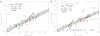 |
Fig. 5 Dependence of the radio luminosity of the POETS sample on the H2O maser (panel a) and bolometric (panel b) luminosities (Sect. 4.5). Radio continuum luminosities have been normalized to 8 GHz for comparison with previous works, and a logarithmic scale is used. Panel a: red diamonds indicate the POETS sample (Table 1); cyan circles denote additional H2O maser sites associated with luminous, prototypical radio thermal jets (Table 3); green circles represent low-luminosity H2O maser sites (from Furuya et al. 2003). The dotted bold line traces the χ2 fit to the sample distribution; the gray shadow shows the dispersion (1σ) about the best fit. The parameters and uncertainties of the best fit, q and p, are reported in the upper left, together with the linear correlation coefficient of the distribution (r). Panel b: same symbols as in panela. The parameters of the best fit, h and k, are to be compared with, e.g., Anglada et al. (2015); Purser et al. (2016). The best fit to the low-mass radio jet luminosites is drawn with a dash-dotted line (from Anglada 1995). The solid line traces the ionized flux expected from the Lyman continuum of ZAMS stars earlier than B8 (seeSect. 4.5). For ZAMS stars, spectral types, corresponding to a given luminosity, are indicated in blue near the lower axis (from Thompson 1984). The pink circle indicates the bolometric and radio luminosities of source S255 NIRS3 during its recent accretion burst, for comparison (Caratti o Garatti et al. 2017; Cesaroni et al. 2018). |
5 Conclusions
We report on a multifrequency VLA survey of radio continuum emission toward a large sample of H2O maser sites (36) entitled the Protostellar Outflows at the EarliesT Stages (POETS) survey. We extend the early work by Tofani et al. (1995) with the idea of combining the information on maser lines and free–free continuum to study the engines of molecular outflows. These observations achieve sensitivities as low as 5 μJy beam−1 and probe angular scales as small as 0.′′1.
Our results can be summarized as follows:
- 1.
This is the first systematic survey toward H2O maser sites conducted at high angular resolution and different frequency bands (C, Ku, and K). At the current sensitivity, the detection rate of 22 GHz continuum emission, within a few 1000 au from the H2O masers, is 100%.
- 2.
The radio continuum fluxes are well below those expected to be due to the Lyman flux of ZAMS stars, suggesting that the young stars exciting the continuum emission are at an early stage of evolution. Spectral indexes (α) between 1 and 7 cm are generally positive and below 1.3; a few sources are associated with optically thin and thick emissionat the longer and shorter wavelengths, respectively. These results are consistent with the radio continuum emission tracing the ionized gas component of stellar winds and jets. We discuss a number of scenarios for thermal jet emission, such as in cores with moderate optical depth, surrounded by optically thin extended emission and knots (e.g., Sects. 4.1–4.4).
- 3.
Radio thermal jets associated with H2O maser emission show a strong correlation (r > 0.8) with both the isotropic H2O maser luminosity and the bolometric luminosity of the young stars (Fig. 5). This correlation seems to be independent of the spectral type of the young stars. In turn, these findings support the idea that their radio continuum flux is mainly produced through shock ionization, given that (i) H2O masers also trace shocked gas in which stellar winds and jets impact ambient gas, and (ii) photoionization is not effective for ZAMS stars later than B5. Alternatively, we can conclude that H2O masers are preferred signposts of radio thermal jets, when the stars are not evolved and associated with bright radio continuum (≫1 mJy).
In a following paper in the series, we will study the energetics of (proto)stellar winds and jets, by combining the mass loss rate estimated from the radio continuum observations with the gas kinematics traced by the H2O maser spots.
Acknowledgements
Comments from an anonymous referee are gratefully acknowledged. The authors thanks Sergio Dzib, Carlos Carrasco-González, Mark Reid, Riccardo Cesaroni, and Roberto Galván-Madrid for fruitful discussion in preparation. A.S. gratefully acknowledges financial support by the Deutsche Forschungsgemeinschaft (DFG) Priority Program 1573.
Appendix A Variations in the spectral index maps
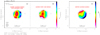 |
Fig. A.1 Simulated spectral index maps for field G111.24−1.24 in Fig. A.2. Labels and symbols as in Fig. 1. Panels a–c: spectral index maps (colors) obtained assuming three different source models at the C, Ku, and K bands. Black contours are those of the observed average brightness map for a direct comparison with Fig. A.2. The cross in panels a and b indicate the peak position of the observed C-band emission. |
In Fig. A.2, the spectral index maps that we produced by combining observations at multiple frequency bands show regular gradients across the radio continuum emission. We show that these gradients can be produced by small position shifts between the radio continuum maps at the different frequencies.
As an example, we make use of the tasks simobserve and clean of CASA to simulate the spectral index map observed for the field G111.24−1.24 (Fig. A.2). The radio continuum emission in G111.24−1.24 is compact with respect to the VLA beam at the different frequencies (Col. 4 of Table A.1). We used the CASA toolkit to set the source model at the C, Ku, and K bands separately and assume that the source has a Gaussian brightness distribution; we took the flux densities at each frequency from Col. 10 of Table A.1.
First, we considered a case in which the source size is scaled to a third of the beam at each frequency. We also aligned the Gaussian peaks at the peak position of the C-band emission (Cols. 6 and 7 of Table A.1). We then simulated the uv datasets at each frequency with the task simobserve of CASA, under the same conditions of our observations (Table 2) but setting a long integration time, so that the spectral index maps are not limited by sensitivity.
In panel a of Fig. A.1, we show the modeled spectral index map cleaned with the same parameters of the
observed map (Sect. 3.3). To facilitate the comparison with Fig. A.2, we also draw the contours of the observed average brightness map. The modeled spectral index map ranges from 1.2 to 1.7 up to 3σ from the (average) spectral index computed with the integrated fluxes (1.1 ± 0.2). Close to the C-band peak (cross) and along the beam major axis the spectral index values are within 1σ of the average spectral index. For further comparison, we repeated the procedure assuming point-like emission at each frequency (panel b), but we assumed all other parameters were equal. We found that the spectral index distribution did not change significantly from panels a to b.
Finally, in panel c of Fig. A.1, we show a third case in which we shifted the peak positions at each frequency according to Cols. 6 and 7 of Table A.1. The largest offset of 0.′′ 07, between the C- and Ku-band peaks, is within the uncertainty of the calibration. The source size was scaled to a third of the beam at each frequency. The modeled spectral index map spans a larger range of values, from 0.6 to 2.1, and shows a regular gradient from the southwest to the northeast. This gradient is approximately the same as in the observed map, demonstrating that it is caused by the small offsets between the continuum maps at different frequencies.
This example shows that it is important to exert caution when interpreting spectral index gradients in the α-maps.
Properties of the radio continuum sources.
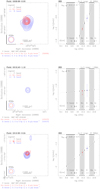 |
Fig. A.2 Foreach source in Table 1, analysis of the VLA radio continuum emission associated with the H2O maser sites. Labels and symbols as in Figs. 1–4. |
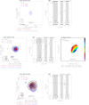 |
Fig. A.2 continued. |
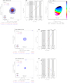 |
Fig. A.2 continued. |
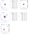 |
Fig. A.2 continued. |
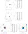 |
Fig. A.2 continued. |
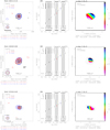 |
Fig. A.2 continued. |
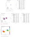 |
Fig. A.2 continued. |
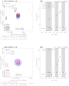 |
Fig. A.2 continued. |
References
- Anglada, G. 1995, in Revista Mexicana de Astronomia y Astrofisica Conference Series, eds. S. Lizano & J. M. Torrelles, 1,67 [NASA ADS] [Google Scholar]
- Anglada, G. 1996, in Radio Emission from the Stars and the Sun, eds. A. R. Taylor & J. M. Paredes, Astronomical Society of the Pacific Conference Series, 93, 3 [Google Scholar]
- Anglada, G., Villuendas, E., Estalella, R., et al. 1998, AJ, 116, 2953 [NASA ADS] [CrossRef] [Google Scholar]
- Anglada, G., Rodríguez, L. F., & Carrasco-Gonzalez, C. 2015, Advancing Astrophysics with the Square Kilometre Array (AASKA14), 121 [CrossRef] [Google Scholar]
- Arce, H. G., Shepherd, D., Gueth, F., et al. 2007, Protostars and Planets V, (Tucson, AZ: University Arizona Press) 245 [Google Scholar]
- Beuther, H., Schilke, P., Sridharan, T. K., et al. 2002, A&A, 383, 892 [NASA ADS] [CrossRef] [EDP Sciences] [Google Scholar]
- Brunthaler, A., Reid, M. J., Menten, K. M., et al. 2009, ApJ, 693, 424 [NASA ADS] [CrossRef] [Google Scholar]
- Burns, R. A., Handa, T., Nagayama, T., Sunada, K., & Omodaka, T. 2016, MNRAS, 460, 283 [NASA ADS] [CrossRef] [Google Scholar]
- Burns, R. A., Handa, T., Imai, H., et al. 2017, MNRAS, 467, 2367 [NASA ADS] [Google Scholar]
- Caratti o Garatti, A., Stecklum, B., Garcia Lopez, R., et al. 2017, Nat. Phys., 13, 276 [NASA ADS] [CrossRef] [Google Scholar]
- Carrasco-González, C., Rodríguez, L. F., Anglada, G., et al. 2010, Science, 330, 1209 [NASA ADS] [CrossRef] [PubMed] [Google Scholar]
- Cesaroni, R., Moscadelli, L., Neri, R., et al. 2018, A&A, 612, A103 [NASA ADS] [CrossRef] [EDP Sciences] [Google Scholar]
- Chen, H.-R. V., Keto, E., Zhang, Q., et al. 2016, ApJ, 823, 125 [NASA ADS] [CrossRef] [Google Scholar]
- Churchwell, E. 1999, in NATO Advanced Science Institutes (ASI) Series C, ed. C. J. Lada & N. D. Kylafis, 540, 515 [Google Scholar]
- Churchwell, E. 2002, ARA&A, 40, 27 [Google Scholar]
- Curiel, S., Canto, J., & Rodriguez, L. F. 1987, Rev. Mexicana Astron. Astrofis., 14, 595 [NASA ADS] [Google Scholar]
- Curiel, S., Rodriguez, L. F., Bohigas, J., et al. 1989, Astrophys. Lett. Commun., 27, 299 [NASA ADS] [Google Scholar]
- Curiel, S., Ho, P. T. P., Patel, N. A., et al. 2006, ApJ, 638, 878 [NASA ADS] [CrossRef] [Google Scholar]
- Davies, B., Lumsden, S. L., Hoare, M. G., Oudmaijer, R. D., & de Wit, W.-J. 2010, MNRAS, 402, 1504 [NASA ADS] [CrossRef] [Google Scholar]
- De Buizer, J. M., Liu, M., Tan, J. C., et al. 2017, ApJ, 843, 33 [NASA ADS] [CrossRef] [Google Scholar]
- de Wit, W. J., Hoare, M. G., Oudmaijer, R. D., & Lumsden, S. L. 2010, A&A, 515, A45 [NASA ADS] [CrossRef] [EDP Sciences] [Google Scholar]
- Felli, M., Palagi, F., & Tofani, G. 1992, A&A, 255, 293 [NASA ADS] [Google Scholar]
- Frank, A., Ray, T. P., Cabrit, S., et al. 2014, Protostars and Planets VI (Tucson, AZ: University Arizona Press), 451 [Google Scholar]
- Furuya, R. S., Kitamura, Y., Wootten, A., Claussen, M. J., & Kawabe, R. 2003, ApJS, 144, 71 [NASA ADS] [CrossRef] [Google Scholar]
- Galván-Madrid, R., Zhang, Q., Keto, E., et al. 2010, ApJ, 725, 17 [NASA ADS] [CrossRef] [Google Scholar]
- Goddi, C., & Moscadelli, L. 2006, A&A, 447, 577 [NASA ADS] [CrossRef] [EDP Sciences] [Google Scholar]
- Goddi, C., Moscadelli, L., Torrelles, J. M., Uscanga, L., & Cesaroni, R. 2006, A&A, 447, L9 [NASA ADS] [CrossRef] [EDP Sciences] [Google Scholar]
- Goddi, C., Moscadelli, L., Sanna, A., Cesaroni, R., & Minier, V. 2007, A&A, 461, 1027 [NASA ADS] [CrossRef] [EDP Sciences] [Google Scholar]
- Goddi, C., Moscadelli, L., & Sanna, A. 2011, A&A, 535, L8 [NASA ADS] [CrossRef] [EDP Sciences] [Google Scholar]
- Hoare, M. G., & Franco, J. 2007, Astrophys. Space Sci. Proc., 1, 61 [NASA ADS] [CrossRef] [Google Scholar]
- Hoare, M. G., Kurtz, S. E., Lizano, S., Keto, E., & Hofner, P. 2007, Protostars and Planets V (Tucson, AZ: University Arizona Press), 181 [Google Scholar]
- Hofner, P., Cesaroni, R., Olmi, L., et al. 2007, A&A, 465, 197 [NASA ADS] [CrossRef] [EDP Sciences] [Google Scholar]
- Hollenbach, D., Elitzur, M., & McKee, C. F. 2013, ApJ, 773, 70 [NASA ADS] [CrossRef] [Google Scholar]
- Hunter, T. R., Brogan, C. L., Bartkiewicz, A., et al. 2018, ArXiv e-prints [arXiv:1806.06981] [Google Scholar]
- Johnston, K. G., Shepherd, D. S., Robitaille, T. P., & Wood, K. 2013, A&A, 551, A43 [NASA ADS] [CrossRef] [EDP Sciences] [Google Scholar]
- Marti, J., Rodriguez, L. F., & Reipurth, B. 1993, ApJ, 416, 208 [NASA ADS] [CrossRef] [Google Scholar]
- Maud, L. T., Moore, T. J. T., Lumsden, S. L., et al. 2015, MNRAS, 453, 645 [NASA ADS] [CrossRef] [Google Scholar]
- Maud, L. T., Hoare, M. G., Galván-Madrid, R., et al. 2017, MNRAS, 467, L120 [NASA ADS] [Google Scholar]
- Moscadelli, L., Reid, M. J., Menten, K. M., et al. 2009, ApJ, 693, 406 [NASA ADS] [CrossRef] [Google Scholar]
- Moscadelli, L., Cesaroni, R., Rioja, M. J., Dodson, R., & Reid, M. J. 2011, A&A, 526, A66 [NASA ADS] [CrossRef] [EDP Sciences] [Google Scholar]
- Moscadelli, L., Li, J. J., Cesaroni, R., et al. 2013, A&A, 549, A122 [NASA ADS] [CrossRef] [EDP Sciences] [Google Scholar]
- Moscadelli, L., Sánchez-Monge, Á., Goddi, C., et al. 2016, A&A, 585, A71 [NASA ADS] [CrossRef] [EDP Sciences] [Google Scholar]
- Panagia, N., & Felli, M. 1975, A&A, 39, 1 [Google Scholar]
- Purser, S. J. D., Lumsden, S. L., Hoare, M. G., et al. 2016, MNRAS, 460, 1039 [NASA ADS] [CrossRef] [Google Scholar]
- Qiu, K., Zhang, Q., Wu, J., & Chen, H.-R. 2009, ApJ, 696, 66 [NASA ADS] [CrossRef] [Google Scholar]
- Rau, U., & Cornwell, T. J. 2011, A&A, 532, A71 [NASA ADS] [CrossRef] [EDP Sciences] [Google Scholar]
- Reid, M. J., Menten, K. M., Brunthaler, A., et al. 2014, ApJ, 783, 130 [Google Scholar]
- Rengarajan, T. N., & Ho, P. T. P. 1996, ApJ, 465, 363 [NASA ADS] [CrossRef] [Google Scholar]
- Reynolds, S. P. 1986, ApJ, 304, 713 [NASA ADS] [CrossRef] [Google Scholar]
- Rodriguez, L. F., Moran, J. M., Ho, P. T. P., & Gottlieb, E. W. 1980, ApJ, 235, 845 [NASA ADS] [CrossRef] [Google Scholar]
- Rodriguez, L. F., Garay, G., Curiel, S., et al. 1994, ApJ, 430, L65 [NASA ADS] [CrossRef] [Google Scholar]
- Rodríguez-Kamenetzky, A., Carrasco-González, C., Araudo, A., et al. 2017, ApJ, 851, 16 [NASA ADS] [CrossRef] [Google Scholar]
- Rosero, V., Hofner, P., Claussen, M., et al. 2016, ApJS, 227, 25 [NASA ADS] [CrossRef] [Google Scholar]
- Rygl, K. L. J., Brunthaler, A., Sanna, A., et al. 2012, A&A, 539, A79 [NASA ADS] [CrossRef] [EDP Sciences] [Google Scholar]
- Sanna, A., Moscadelli, L., Cesaroni, R., et al. 2010a, A&A, 517, A71 [NASA ADS] [CrossRef] [EDP Sciences] [Google Scholar]
- Sanna, A., Moscadelli, L., Cesaroni, R., et al. 2010b, A&A, 517, A78 [NASA ADS] [CrossRef] [EDP Sciences] [Google Scholar]
- Sanna, A., Reid, M. J., Carrasco-González, C., et al. 2012, ApJ, 745, 191 [NASA ADS] [CrossRef] [Google Scholar]
- Sanna, A., Cesaroni, R., Moscadelli, L., et al. 2014, A&A, 565, A34 [NASA ADS] [CrossRef] [EDP Sciences] [Google Scholar]
- Sanna, A., Moscadelli, L., Cesaroni, R., et al. 2016, A&A, 596, L2 [NASA ADS] [CrossRef] [EDP Sciences] [Google Scholar]
- Tanaka, K. E. I., Tan, J. C., & Zhang, Y. 2016, ApJ, 818, 52 [NASA ADS] [CrossRef] [Google Scholar]
- Thompson, R. I. 1984, ApJ, 283, 165 [NASA ADS] [CrossRef] [Google Scholar]
- Tofani, G., Felli, M., Taylor, G. B., & Hunter, T. R. 1995, A&AS, 112, 299 [NASA ADS] [Google Scholar]
- Torrelles, J. M., Patel, N. A., Anglada, G., et al. 2003, ApJ, 598, L115 [NASA ADS] [CrossRef] [Google Scholar]
- van der Tak, F. F. S., & Menten, K. M. 2005, A&A, 437, 947 [NASA ADS] [CrossRef] [EDP Sciences] [Google Scholar]
The National Radio Astronomy Observatory is a facility of the National Science Foundation operated under cooperative agreement by Associated Universities, Inc.
Flux densities of components VLA–1 and VLA–2 were computed within squared boxes centered on each peak. The box size was set so as to minimize the contribution of sources VLA–3 and VLA–4, based on the Ku-band map.
Bolometric luminosities were measured with the Herschel Hi-GAL fluxes for 60% of the POETS sample and probe angular scales of less than 30″. For the remaining fields, bolometric luminosities were estimated on the basis of archival mid-infrared (WISE and MSX) and far-infrared (IRAS) fluxes (Table 1 of Moscadelli et al. 2016).
We note that, even though masers might be amplifying a background continuum, we exclude a systematic effect on Fig. 5 A for two reasons: (i) 22.2 GHz H2O masers do not necessarily overlap with the 22 GHz continuum, and (ii) there is no spatial correlation between the 22 GHz continuum brightness and the distribution of the brightest H2O masers (e.g., Moscadelli et al. 2016).
All Tables
All Figures
|
Fig. 1 Example of stellar wind emission from a double system: H2O maser site G229.57+0.15 (Sect. 4.1). Panela: superposition of the VLA maps for the C- (grayscale/black contours), Ku- (red), and K-band (blue) emission (Sect. 3.1). Contour levels, at multiples of the 1σ rms, are indicated in the footnote. Synthesized beams for each band are shown in the bottom left corner. A scale bar in units of au is drawn near the bottom axis. Three distinct continuum sources are identified and labeled VLA–1, VLA–2, and VLA–3 from the brightest to the faintest. Panelsb–d: spectral energy distribution for the three sources identified in panela separately (Sect. 3.2). Each plot shows the logarithm of the integrated flux (in mJy) as a function of the logarithm of the observed frequency (in Hz). Various frequency bands are labeled near the bottom axis together with the reference wavelength; gray shades indicate the boundary of each band. For each band combination, the linear spectral index value (α) and its uncertainty are specified in the upper left corner. The common range of uv distances (e.g., 40–800 kλ in panelb and full uv range in panel d) used to compute the integrated fluxes among the bands is indicated in the upper right. Panele: color map of the linear spectral index (α) computed with the MFS algorithm of the task clean of CASA (Sect. 3.3). Frequency bands used to fit the spectralindex are listed on top; spectral index values are quantified by the right-hand wedge. The uncertainty on α is indicated in the wedge label; this value is an upper limit that holds at the 7σ contour of the average brightness map (black contours). Contour levels of the average brightness map, at multiples of the 1σ rms, are indicated in the footnote; the central frequency (ν0) of the average brightness map is specified in the legend. The absolute coordinates of (0,0) offset are indicated in the footnote (see Table 1). Radio continuum components and the scale bar as in panela. |
| In the text | |
|
Fig. 2 Example of optically thin thermal jet emission: H2O maser site G090.21+2.32 (Sect. 4.2). Labels and symbols as in Fig. 1. Panelb: we divided the C and K bands in twosub-bands to show that the spectral index within each band is consistent with the spectral index interpolated to the Ku-band frequency. The SED shows a region of optically thin (resolved) emission below 15 GHz and a region of optically thick (compact) emission above 15 GHz. The spectral index map of panelc was computed within the (linear) range of optically thin emission (C and Ku bands only). |
| In the text | |
|
Fig. 3 Example of radio thermal jet (VLA–2) near a HCH II region (VLA–1): H2O maser site G240.32+0.07 (Sect. 4.3). Labels and symbols as in Fig. 1. The SED of source VLA–1 was fitted with a model of homogeneous H II region (panelb) with Strömgren radius of 870 au and number of Lyman photons of 3 × 1046 s−1. This model accurately reproduces the observed fluxes at each band. Thanks to the high S/N, in panels d and e we can determine the spectral index maps of the C and Ku bands separately with an uncertainty better than ±0.2. The average brightness map (contours) is that of the Ku band in both panels d and e, for comparison. The spectral index maps trace the turnover of the continuum spectrum for source VLA–1 from α = 1.0–6.0 between 4 and 8 GHz (paneld) to α = –0.1 above 15 GHz (panele). |
| In the text | |
|
Fig. 4 Example of radio thermal jet (VLA–1) with nearby knot (VLA–2): H2O maser site G012.91−0.26 or W33A (Sect. 4.4). Labels and symbols as in Fig. 1. Two radio continuum sources are detected at both C and K bands along a position angle of approximately 152° (panel a): the brightest emission coincides in position with the brightest millimeter source in the dusty core MM1. Panelsb and c: we fitted the spectral index of sources VLA–1 and VLA–2 with the measured fluxes at C and K bands, after dividing the K-band observations into two sub-bands, each spanning 4 GHz. Panelb: fluxes reported in the literature at X (pink), Ku (red), and Q (cyan) bands are consistent with a single linear slope, i.e., from 4 to 43 GHz. The radio continuum emission associated with W33A–MM1 can be interpreted as a thermal jet, whose components VLA–1 and VLA–2 indicate the ionized gas closest to the driving source, namely, MM1-main, and a knot of shocked gas along the jet direction, respectively. |
| In the text | |
|
Fig. 5 Dependence of the radio luminosity of the POETS sample on the H2O maser (panel a) and bolometric (panel b) luminosities (Sect. 4.5). Radio continuum luminosities have been normalized to 8 GHz for comparison with previous works, and a logarithmic scale is used. Panel a: red diamonds indicate the POETS sample (Table 1); cyan circles denote additional H2O maser sites associated with luminous, prototypical radio thermal jets (Table 3); green circles represent low-luminosity H2O maser sites (from Furuya et al. 2003). The dotted bold line traces the χ2 fit to the sample distribution; the gray shadow shows the dispersion (1σ) about the best fit. The parameters and uncertainties of the best fit, q and p, are reported in the upper left, together with the linear correlation coefficient of the distribution (r). Panel b: same symbols as in panela. The parameters of the best fit, h and k, are to be compared with, e.g., Anglada et al. (2015); Purser et al. (2016). The best fit to the low-mass radio jet luminosites is drawn with a dash-dotted line (from Anglada 1995). The solid line traces the ionized flux expected from the Lyman continuum of ZAMS stars earlier than B8 (seeSect. 4.5). For ZAMS stars, spectral types, corresponding to a given luminosity, are indicated in blue near the lower axis (from Thompson 1984). The pink circle indicates the bolometric and radio luminosities of source S255 NIRS3 during its recent accretion burst, for comparison (Caratti o Garatti et al. 2017; Cesaroni et al. 2018). |
| In the text | |
|
Fig. A.1 Simulated spectral index maps for field G111.24−1.24 in Fig. A.2. Labels and symbols as in Fig. 1. Panels a–c: spectral index maps (colors) obtained assuming three different source models at the C, Ku, and K bands. Black contours are those of the observed average brightness map for a direct comparison with Fig. A.2. The cross in panels a and b indicate the peak position of the observed C-band emission. |
| In the text | |
|
Fig. A.2 Foreach source in Table 1, analysis of the VLA radio continuum emission associated with the H2O maser sites. Labels and symbols as in Figs. 1–4. |
| In the text | |
|
Fig. A.2 continued. |
| In the text | |
|
Fig. A.2 continued. |
| In the text | |
|
Fig. A.2 continued. |
| In the text | |
|
Fig. A.2 continued. |
| In the text | |
|
Fig. A.2 continued. |
| In the text | |
|
Fig. A.2 continued. |
| In the text | |
|
Fig. A.2 continued. |
| In the text | |
Current usage metrics show cumulative count of Article Views (full-text article views including HTML views, PDF and ePub downloads, according to the available data) and Abstracts Views on Vision4Press platform.
Data correspond to usage on the plateform after 2015. The current usage metrics is available 48-96 hours after online publication and is updated daily on week days.
Initial download of the metrics may take a while.