| Issue |
A&A
Volume 699, July 2025
|
|
|---|---|---|
| Article Number | A5 | |
| Number of page(s) | 18 | |
| Section | Extragalactic astronomy | |
| DOI | https://doi.org/10.1051/0004-6361/202452990 | |
| Published online | 25 June 2025 | |
The ALMA-CRISTAL survey
Complex kinematics of galaxies at the end of the reionization era
1
Instituto de Estudios Astrofísicos, Facultad de Ingeniería y Ciencias, Universidad Diego Portales, Ejército Libertador 441, 8370191 Santiago, Chile
2
Instituto de Astrofísica and Centro de Astroingeniería, Facultad de Física, Pontificia Universidad Católica de Chile, Casilla 306, Santiago 22, Chile
3
Department of Physics and Astronomy and George P. and Cynthia Woods Mitchell Institute for Fundamental Physics and Astronomy, Texas A&M University, College Station, TX, USA
4
Departamento de Astronomía, Universidad de Concepción, Barrio Universitario, Concepción, Chile
5
Department of Physics, University of Oxford, Denys Wilkinson Building, Keble Road, Oxford OX1 3RH, UK
6
Kavli Institute for Cosmology, University of Cambridge, Madingley Road, Cambridge CB3 0HA, UK
7
Cavendish Laboratory – Astrophysics Group, University of Cambridge, 19 JJ Thomson Avenue, Cambridge CB3 0HE, UK
8
Max-Planck-Institut für extraterrestrische Physik, Gießenbachstraße 1, 85748 Garching, Germany
9
Sterrenkundig Observatorium, Ghent University, Krijgslaan 281 – S9, B-9000 Gent, Belgium
10
Institute of Astrophysics, Foundation for Research and Technology-Hellas (FORTH), Heraklion 70013, Greece
11
School of Sciences, European University Cyprus, Diogenes street, Engomi, 1516 Nicosia, Cyprus
12
Scuola Normale Superiore, Piazza dei Cavalieri 7, 56126 Pisa, Italy
13
Department of Astronomy, School of Science, SOKENDAI (The Graduate University for Advanced Studies), 2-21-1 Osawa, Mitaka, Tokyo 181-8588, Japan
14
National Astronomical Observatory of Japan, 2-21-1 Osawa, Mitaka, Tokyo 181-8588, Japan
15
Dipartimento di Fisica e Astronomia, Università di Firenze, Via G. Sansone 1, 50019 Sesto F.no (Firenze), Italy
16
INAF - Osservatorio Astrofisico di Arcetri, largo E. Fermi 5, 50127 Firenze, Italy
17
Department of Astronomy, The University of Tokyo, 7-3-1 Hongo, Bunkyo, Tokyo 113-0033, Japan
18
Dept. Física Teórica y del Cosmos, Universidad de Granada, 18017 Granada, Spain
19
Instituto Universitario Carlos I de Física Teórica y Computacional, Universidad de Granada, 18071 Granada, Spain
20
Centro de Astrobiología (CAB), CSIC–INTA, Cra. de Ajalvir Km. 4, 28850 Torrejón de Ardoz, Madrid, Spain
21
Faculty of Engineering, Hokkai-Gakuen University, Toyohira-ku, Sapporo 062-8605, Japan
⋆ Corresponding author: This email address is being protected from spambots. You need JavaScript enabled to view it.
Received:
13
November
2024
Accepted:
23
April
2025
Abstract
The history of gas assembly in the early galaxies is reflected in their complex kinematics. While a considerable fraction of galaxies at z ∼ 5 are consistent with rotating disks, recent studies indicate that the dominant galaxy assembly mechanism corresponds to minor and major mergers. Despite important progress, the dynamical classification of galaxies at these epochs is still severely limited by observations’ angular and spectral resolution. We present a detailed morphological and kinematic analysis of the far-infrared-bright main-sequence galaxy HZ10 (CRISTAL-22) at z = 5.65, making use of new sensitive high-resolution (≲0.3″) [C II] 158μm ALMA and rest-frame optical JWST/NIRSpec integral field spectroscopy observations. These observations reveal a previously unresolved complex morphology and kinematics of the HZ10 system. Using position-velocity diagrams, we confirm that HZ10 is not a single massive galaxy but instead consists of at least three components in close projected separation along the east-to-west direction. We find a [C II]-bright central component (C) separated by 1.5 kpc and 4 kpc from the east (E) and west (W) components, respectively. Our [C II] observations resolve the HZ10-C component, and we find a velocity gradient that could be produced by either rotation or a close-in merger. We tested the rotating disk possibility using DysmalPy kinematic modeling and the PVsplit tool. Based on this, we propose the most plausible dynamical scenario for HZ10: a double merger, where the companion galaxy HZ10-W merges with the disturbed rotating disk formed by the HZ10-C and HZ10-E components. Additionally, from the comparison between ALMA [C II] 158μm and JWST/NIRSpec data, we find that [C II] 158μm emission closely resembles the broad [O III] 5007Å emission both spatially and kinematically. The kinematic similarity reflects the interacting nature of the system and suggests that ionized and neutral gas phases in HZ10 are well mixed.
Key words: galaxies: high-redshift / galaxies: ISM / galaxies: individual: HZ10 / galaxies: kinematics and dynamics
© The Authors 2025
 Open Access article, published by EDP Sciences, under the terms of the Creative Commons Attribution License (https://creativecommons.org/licenses/by/4.0), which permits unrestricted use, distribution, and reproduction in any medium, provided the original work is properly cited.
This article is published in open access under the Subscribe to Open model. This email address is being protected from spambots. You need JavaScript enabled to view it. to support open access publication.
1. Introduction
Studying early galaxies and early-stage galaxy assemblies is essential for understanding the fundamental processes of galaxy formation and evolution. While present-day galaxies are mostly quiescent, this picture differs dramatically from the early Universe, when galaxies were undergoing active interactions that shaped their assembly history.
According to observations and simulations, the relative contribution of smooth cold gas accretion from the intergalactic medium and major mergers to the galaxy mass growth evolves over time (Overzier 2016). While at low redshifts the mass assembly is dominated by smooth gas accretion, at higher redshifts, z > 3, merger processes become increasingly important (e.g., Duncan et al. 2019; Romano et al. 2021).
The morpho-kinematic analysis of emission lines in the spectra of galaxies is a powerful tool for determining the history of the gas assembly of galaxies. This method, however, in addition to high spectral resolution, requires high spatial resolution, which is challenging to achieve at high redshifts. While in the local Universe one of the most accessible tracers used to study the galaxy kinematics is the H I 21cm emission line (e.g., Walter et al. 2008; Begum et al. 2008; Hunter et al. 2012; Patra et al. 2016; de Blok et al. 2024), at high redshifts such observations are currently unavailable. So far, the most distant H I 21cm emission line detections are at z ≈ 0.4 (Xi et al. 2024) from a few non-lensed galaxies and at z ≈ 1.3 from one strongly lensed galaxy (Chakraborty & Roy 2023). While the Square Kilometre Array shows promise in exploring H I 21cm emission from the early Universe, studying galaxy kinematics at redshifts z > 2 will continue to be challenging (Staveley-Smith & Oosterloo 2015).
However, the [C II] fine structure 
 transition at a rest-frame wavelength of 158 μm provides a reasonable alternative. Since this line is easily excited by collisions of the carbon ion with electrons, as well as molecular and atomic hydrogen (Goldsmith et al. 2012), it traces multiple gas phases and is widely regarded as a good probe of galaxy kinematics in the early Universe (de Blok et al. 2016). Being the key coolant of interstellar gas in galaxies and one of the strongest far-infrared emission lines, [C II] is detectable up to very high redshifts (e.g., up to z ∼ 8.5; Bakx et al. 2020; Bouwens et al. 2022; Fujimoto et al. 2024).
A major step forward in the systematic study of high-redshift galaxies has been possible thanks to the Atacama Large Millimeter/submillimeter Array (ALMA) Large Program to INvestigate [C II] at Early times (ALPINE; Le Fèvre et al. 2020) and the Reionization Era Bright Emission Line Survey (REBELS; Bouwens et al. 2022). Among many other results, such as the presence of extended [C II] halos around early star-forming galaxies (e.g., Fujimoto et al. 2019, 2020; Ginolfi et al. 2020), these surveys revealed a significant fraction of merging galaxies at z ∼ 5 (Romano et al. 2021), yet with a considerable fraction of possible rotating disks, even at z ∼ 7 (Jones et al. 2021; Smit et al. 2018). The ALPINE and most of the REBELS observations, however, were limited by their coarse angular resolution (∼1″), and therefore targeted higher-resolution observations are needed to investigate the morphology and kinematics of galaxies at z > 4. These previously barely resolved observations are not suited for dynamical analysis, and using them could lead to a considerable misclassification between rotation disks and mergers (e.g., Rizzo et al. 2022).
Thanks to the unprecedented spatial resolution attainable with ALMA and the James Webb Space Telescope (JWST), we are entering the era of kiloparsec-scale studies of galaxies within the first billion years of the Universe (e.g., Herrera-Camus et al. 2022; Posses et al. 2023; Mitsuhashi et al. 2024; Solimano et al. 2025, 2024; Posses et al. 2025; Villanueva et al. 2024; Jones et al. 2024; Ikeda et al. 2025). High-resolution ALMA observations have confirmed the presence of disk-like galaxies at very high redshifts, z ∼ 6 − 7 (e.g., Neeleman et al. 2023; Rowland et al. 2024); however, in many cases they unveiled a complex morphology and interactions (e.g., Solimano et al. 2024; Posses et al. 2025; Ikeda et al. 2025). Moreover, these observations confirmed the existence of extended [C II] emission and its possible connection to mergers and/or outflows (e.g., Pizzati et al. 2020; Akins et al. 2022; Ikeda et al. 2025). However, such high-resolution observations remain scarce, and even with the advent of JWST, observations of [C II] remain essential as [C II] emission in galaxies predominantly originates from photodissociation regions with contributions from atomic neutral and ionized gas (e.g., Pineda et al. 2013; Pallottini et al. 2017; Olsen et al. 2017) and typically traces galaxy kinematics (e.g., Kohandel et al. 2019). In contrast, rest-frame optical line kinematics such as Hα and [O III] might be dominated by outflows.
Using the new high-angular-resolution ALMA observations (∼0.3″) presented in this work, complemented by JWST data, we performed detailed morphological and kinematic analyses of the cool and ionized gas in HZ10, a far-infrared-bright and gas-rich galaxy in the Cosmic Evolution Survey Deep Field (COSMOS) at z = 5.65. This source is part of a protocluster with recent or ongoing major merging processes (Pavesi et al. 2018) and thus provides an exceptional opportunity to examine the complex picture of starburst-driven phenomena and interactions occurring in overdensity environments at high redshifts (Oteo et al. 2018; Guaita et al. 2022; Lewis et al. 2018).
In Sect. 2 we describe previous studies of HZ10 and its neighborhood. In Sect. 3 we describe the sensitive high-resolution ALMA [C II] observations used for the analysis and briefly describe the Hubble Space Telescope (HST) and JWST data used for the comparison. In Sect. 4 we present moment maps of HZ10 derived from new high-resolution ALMA [C II] observations, along with a 2D parametric modeling of the moment-0 map and a kinematic analysis based on position-velocity (PV) diagrams and rotation curves. In Sect. 5 we present kinematic modeling of the brightest [C II] component of HZ10, assuming this component represents a rotating disk. We also examine the validity of this assumption, considering alternative dynamic scenarios for the system, such as a triple merger or a merger involving a disturbed disk and a satellite galaxy. In Sect. 6 we compare ALMA observations with those from JWST Near InfraRed Spectrograph (NIRSpec). Lastly, we discuss the results and present our conclusions in Sects. 7 and 8, respectively.
Throughout the paper, we adopt a standard flat Λ cold dark matter cosmology with matter and dark energy density parameters Ωm = 0.3 and ΩΛ = 0.7, respectively, and with the reduced Hubble constant h = 0.7, which gives a conversion scale of 5.899 kpc/″ at redshift z = 5.65.
2. Early studies
The HZ10 galaxy was reported for the first time as a Lyα emitter candidate found in the Subaru narrowband imaging survey of the COSMOS field with Suprime-Cam (Murayama et al. 2007). It was later confirmed at a spectroscopic redshift of 5.65 with Keck DEep Imaging Multi-Object Spectrograph (DEIMOS) observations (Mallery et al. 2012). This galaxy was found to be bright in the rest-frame ultraviolet (UV) emission and thus was selected for the ALMA survey of [C II] 158μm and dust continuum emission conducted by Capak et al. (2015).
These observations revealed – in close proximity (at a projected distance of ≈70 kpc) and at the same redshift – another massive gas-rich galaxy, the dusty starburst galaxy CRLE, which was hidden in the previous Subaru and HST images by a foreground galaxy. Photometric and spectroscopic studies of this field showed that HZ10 and CRLE reside in an overdensity of Lyα emitters, resembling an early protocluster at z ∼ 5.7 (Pavesi et al. 2018), hence providing a unique opportunity to shed light on the link between star formation and the environment at the end of the reionization epoch.
HZ10 was found to be a “normal” massive main-sequence galaxy at z = 5.6548 with a stellar mass of log M⋆/M⊙ = 10.39 ± 0.17 (Capak et al. 2015). In addition to [C II] emission, further detection of C III] 1909Å line emission was reported by Markov et al. (2022) thanks to Very Large Telescope (VLT)/X-shooter spectroscopy. These observations showed the metal-rich nature of HZ10 with the gas-phase metallicity with respect to the solar value of  .
.
Using ALMA Pavesi et al. (2016) revealed a weak [N II] 205μm emission. Pavesi et al. (2016) concluded that while the smooth [N II] velocity gradient of HZ10 favored a disk nature of the galaxy, a tentative indication of the spatial and kinematic offset between [N II] and [C II] emission was reminiscent rather of a clumpy disk or a merger. In addition to atomic gas, the molecular phase associated with HZ10 was detected via CO(2-1) emission using the Karl G. Jansky Very Large Array (VLA; Pavesi et al. 2019)1. These observations showed that HZ10 is remarkably rich in molecular gas with the estimated2 log Mgas/M⊙ = 11.1. Moreover, the star-formation efficiency with a gas depletion timescale of ∼1 Gyr of HZ10 seems comparable to lower-redshift (from nearby up to z ∼ 3) disk main-sequence galaxies (Pavesi et al. 2019).
Despite the significant progress made in characterizing HZ10 with the previous barely resolved observations (≳0.6″), the kinematic properties of this galaxy could only be addressed with higher angular resolution data. Recent high-angular resolution JWST/NIRSpec (∼0.15″) integral field spectroscopy (IFS) observations of rest-frame optical emission (Jones et al. 2024) and ALMA (∼0.3″) observations of dust emission (Villanueva et al. 2024) unveiled the complex morphology of HZ10. In this work we address the kinematic properties of HZ10 based on the high angular and spectral resolution [C II] 158μm emission.
3. Observations and data reduction
3.1. ALMA
High-resolution ALMA observations of the [C II] 158μm line and dust continuum emission toward the HZ10 system, including the dusty star-forming galaxy CRLE, were obtained in Cycle 7 under program 2019.1.1075.S (PI: M. Aravena). These ALMA band 7 observations were obtained in C43-4/5 configuration in March 2021, under standard observatory weather conditions. Data calibration was performed using CASA pipeline version 6.4.1.12. No additional flagging was necessary. The brightness of the neighboring CRLE galaxy within the field of view of HZ10 yielded high signal-to-noise continuum emission. We thus conducted standard continuum self-calibration in two stages, masking out the CRLE and HZ10 in the process. The background rms decreased by 21% from 19 to 15 μJy beam−1 for the continuum image.
The signal-to-noise level achieved was not enough to perform line self-calibration. Imaging was performed using the tclean task in CASA following the procedures described in Herrera-Camus et al. (2025).
Due to the high spatial resolution (synthesized beam size of 0.34″ × 0.27″, positional angle of 54.9 degrees, natural weighting) and sensitivity these observations were included as part of the extended sample of the [C II] Resolved ISM in Star-forming ALMA Large program (CRISTAL). The HZ10 system is also denoted as CRISTAL-22 as part of the extended CRISTAL sample. CRISTAL is an ALMA Cycle-8 large program (2021.1.00280.L; PI: R. Herrera-Camus) aimed at getting spatially resolved [C II] and dust continuum observations of main-sequence star-forming galaxies at z ∼ 4 − 6 (Ikeda et al. 2025; Mitsuhashi et al. 2024; Herrera-Camus et al. 2025).
We examined whether our conclusions are sensitive to the Jorsater–van Moorsel (JvM) effect correction (Jorsater & van Moorsel 1995) by cross-checking all the results based on the data cubes with and without JvM correction applied. We conclude that the flux density estimations in the two cases are consistent with each other. Therefore, all the figures throughout the paper are based on the ALMA cubes without JvM correction.
3.2. HST
To compare the ALMA data of dust continuum and [C II] emission with the rest-frame UV HST images we retrieved the available data for the HZ10 field from the Barbara A. Mikulski Archive for Space Telescopes (MAST3). We used archival observations with the Wide Field Camera 3 (WFC3)/F105W filter, which covers the wavelength range of 1300 − 1800 Å in the rest frame at z = 5.65. Images were processed using the standard pipeline, co-added, and aligned to Gaia DR2 (Gaia Collaboration 2018). The image was drizzled with a square kernel and a pixel fraction of 0.5 using the AstroDrizzle routine of DrizzlePac (Hoffmann et al. 2021) to a pixel size of 0.06″.
3.3. JWST
HZ10 is also a part of the JWST/NIRSpec Guaranteed Time Observation GA-NIFS project 1217 (PI: N. Lützgendorf). A detailed analysis of this data is presented in Jones et al. (2024). Jones et al. (2024) compared JWST data astrometry with the Gaia DR3 (Gaia Collaboration 2016, 2021) reference frame and found no significant offset. Due to similar spatial resolution (fiducial point spread function is 0.15″) and high spectral resolution (G395H/F290LP; R ≈ 2700) of JWST/NIRSpec observation, we compared them with our ALMA data.
4. High-resolution ALMA view of HZ10
A comparison of the HST WFC3/F105W image with the [C II] 158μm line and 158μm dust continuum emission of HZ10 is shown in Fig. 1. The new ALMA observations of HZ10 reveal two spatially separated components seen in the [C II] 158μm integrated intensity map, HZ10-C (center) and HZ10-W (west). The HZ10-W component in the HST image is barely detected, likely due to the significant dust attenuation. In addition to the HZ10-C and HZ10-W components, Villanueva et al. (2024) also reported a tentative third component seen as a 158 μm dust continuum emission excess, a dusty bridge connecting the central and west components of HZ10. We address the possible presence of this bridge in [C II] line emission data in the following subsections.
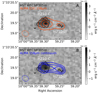 |
Fig. 1. HST WFC3/F105W image of HZ10 in grayscale with black 3σ contours. Panel A: [C II] 158 μm integrated intensity of HZ10 shown with red 5σ, 10σ, and 15σ contours. Panel B: 158 μm continuum of HZ10 shown with blue 3σ, 5σ, and 7σ contours. The beam size of the ALMA observations is shown with an ellipse in the bottom-left corner of each panel. |
4.1. Moment maps
The [C II] integrated intensity (or moment-0 map) is shown on the left panel of Fig. 2. We performed 2D parametric modeling of [C II] integrated intensity map assuming a two-component Sérsic profile and using PyAutoGalaxy (Nightingale et al. 2023), which is based on the probabilistic programming language PyAutoFit (Nightingale et al. 2021). The results along with the other main properties of HZ10 are summarized in Table 1. Details of the 2D parametric modeling are presented in Appendix A.
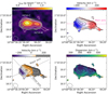 |
Fig. 2. [C II] integrated intensity (moment-0; top left panel), line-of-sight velocity (moment-1; zero velocity is a systemic velocity that corresponds to the rest-frame [C II] frequency at z = 5.6548; top-right panel), adopted line-of-sight velocity (where zero velocity corresponds to the HZ10-C systemic velocity; bottom-left panel), and velocity dispersion (moment-2; bottom-right panel) maps of HZ10. Contours correspond to the 2σ, 3σ, 5σ, 10σ, and 15σ noise levels estimated from the corresponding moment-0 map. The dashed and solid green regions on the moment-0 map correspond to the apertures for the spectra extraction. The dashed gray and dotted pink lines on the moment-1 maps correspond to the axes for the PV diagram calculations. The center of the main and major axes of HZ10 are indicated with the pink vertical line and the gray cross, respectively. An ellipse shows the beam size of the ALMA observations in the bottom-left corner of each panel. |
General properties of the HZ10 system.
To reduce the impact of noisy pixels on the resulting velocity and velocity dispersion maps, we masked those pixels out before calculating moment-1 and moment-2. To do that, we excluded pixels with intensities lower than the 2σ noise level of the respective channel. To ensure that channel masking does not result in underestimations of the velocity dispersion, we compared the dispersion map calculated from the masked data with that derived from the unmasked data cube and found the values to be consistent. The resulting velocity and dispersion maps are shown in the middle and right panels of Fig. 2. The combination of the two spatially separated components, HZ10-C (central, the brightest component on the [C II] moment-0 map) and HZ10-W (to the west of HZ10-C with dimmer, and more compact [C II] emission), results in the smooth velocity gradient on the moment-1 map.
For reference, in Fig. 3, we show the [C II] spectra of the HZ10 complex, extracted from the elliptical aperture shown on the left panel of Fig. 2. The integrated [C II] flux within this aperture is I[C II] = 4.8 ± 0.2 Jy km s−1. This flux is in agreement with the previously reported value estimated from the barely resolved [C II] observations of Pavesi et al. (2016).
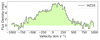 |
Fig. 3. [C II] spectrum of HZ10 complex, extracted from the elliptical aperture, shown on the left panel of Fig. 2. Zero velocity corresponds to the rest-frame [C II] frequency at z = 5.6548. |
4.2. Kinematic analysis
In contrast with the relatively compact HZ10-W component, HZ10-C is resolved along its major kinematic axis in ∼4 independent beams. This allowed us to perform a more detailed kinematic analysis of the HZ10-C component using PV diagrams along the different directions, and by measuring rotation velocity and dispersion curves.
Firstly, we looked at the different kinematic components of HZ10 as a whole complex, including HZ10-W, and calculated the PV diagram along the “main” axis connecting HZ10-C and HZ10-W components (the axis of the highest velocity gradient of the whole system; see the dotted pink line on the middle panel of Fig. 2). We placed a pseudo slit of 10-pixel width, which is comparable with the beam size of the observations (pixel size of the data cube is 0.0372″), along the main axis of HZ10. The result is shown in Fig. 4.
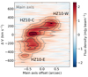 |
Fig. 4. PV diagram calculated along the pseudo slit of 10-pixel width placed along the main axis in Fig. 2. Smoothed gray contours correspond to the 3σ, 5σ, 7σ, and 10σ noise levels. Zero velocity is calculated for the rest-frame [C II] frequency at z = 5.6548. |
Recent high-resolution studies of HZ10 dust continuum emission demonstrated the presence of a dusty bridge seen in 158 μm continuum emission, connecting HZ10-C and HZ10-W components (Villanueva et al. 2024). The presence of such a bridge could result from the interacting nature of the HZ10 complex. Interestingly, at the spatial location of the “bridge” component seen in the 158 μm dust continuum, we do not see such a distinctive component in the residuals of [C II] line emission 2D parametric fit with two Sérsic profiles (see Fig A.1). However, in the PV diagram in Fig. 4, we see [C II] emission connecting HZ10-C and HZ10-W, which could be associated with the dusty “bridge” component or potentially attributed to beam smearing.
The HZ10-W component appears in the PV diagram within the velocity range of ΔV from 100 to 500 km s−1, while the HZ10-C component appears within the velocity range of ΔV from −600 to 200 km s−1 showing a hint of two different subcomponents, a bright one with ΔV from −400 to 200 km s−1 consisting of two bright blobs typical for rotation disks or mergers, and a dimmer one with ΔV from −600 to −400 km s−1. To illustrate the spatial positions of these three components, we show moment-0 maps, calculated within the specified velocity ranges in Fig. 5.
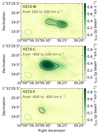 |
Fig. 5. Integrated [C II] intensity calculated within specific velocity ranges, defined from the PV diagram along the main axis of the HZ10 complex. Contours correspond to the 10σ and 15σ noise levels of the corresponding moment-0 maps. The beam size of the ALMA observations is shown with the green ellipse at the bottom-left corner of each panel. |
Considering the velocity and spatial separation between the HZ10-C and HZ10-W components, along with the JWST/NIRSpec integral-field spectroscopic study of the HZ10 system by Jones et al. (2024), which shows that HZ10-W has physical properties such as UV slope and color excess distinct from those of HZ10-C, we further regard HZ10-W as a separate galaxy merging with HZ10-C.
The presence of a dim emission blob to the east of the main HZ10-C component suggests that the bright central complex on the moment-0 map of the whole system could be either a merger or a clumpy disk consisting of two subcomponents – HZ10-C and HZ10-E (east). To calculate PV diagrams for the HZ10-C+HZ10-E complex, we placed a pseudo slit of 10-pixel width along its major and minor kinematic axes. The major kinematic axis is determined from the moment-1 map, defined as the direction of the largest observed velocity difference, and centered on the intensity peak of the moment-0 map4. To estimate the position of the minor kinematic axis, we extracted the velocity rotation curve (discussed later in this section) along the major axis and found it to be symmetric with respect to the systemic velocity of Vsys = −125 km s−1. We used this systemic velocity to define the position of the minor kinematic axis. These axes are shown by the dotted gray lines on the middle panel of Fig. 2). The resulting PV diagrams are shown in Fig. 6.
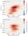 |
Fig. 6. PV diagrams calculated using a pseudo slit of 10-pixel width placed along the major (top panel) and minor (bottom panel) axes of the HZ10-C+HZ10-E complex. Zero velocity is calculated for the rest-frame [C II] frequency at z = 5.6548. Smoothed gray contours correspond to the 3σ, 5σ, 7σ, and 9σ noise levels of the PV diagrams. |
The PV diagram extracted along the major axis of the HZ10-C+HZ10-E system only tentatively resembles the classical S-shape typical for disks with an ordered rotation. Moreover, the asymmetry of the PV diagram, extracted along the minor axis, suggests noncircular motions that could be attributed to the minor interactions and/or nuclear or stellar feedback (e.g., Price et al. 2021; Rizzo et al. 2022). We present a quantitative analysis of the PV diagrams using the kinematic classification tool PVsplit (Rizzo et al. 2022, 2023) in the following section.
To further investigate the nature of the HZ10-C+HZ10-E system, we extracted rotation curves (velocity and dispersion as a function of the spatial offset) along the major axis, which are shown in Fig. 7. We extracted spectra along the major axis using circular apertures with a diameter of 0.26″ (solid green regions on the moment-0 map in Fig. 2), which roughly matches the beam size. The corresponding aperture spectra are shown in Appendix B. The aperture spectra show distinct non-symmetric profiles, partly due to blending velocity components within the apertures from the beam-smearing effect. Therefore, we fit the extracted spectra with single and double Gaussian profiles to calculate velocity centroids and dispersion in each aperture. In cases where the double-component profile fitting effectively results in a single-component solution (i.e., one of the components is poorly constrained), we used only a single-Gaussian model fit (which is common for apertures with a low signal-to-noise ratio). The resulting velocity centroids and dispersion as a function of the aperture position along the major axis are shown in Fig. 7.
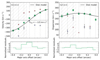 |
Fig. 7. Rotation curves calculated along the major axis of the HZ10-E+HZ10-C complex. Data points correspond to the velocity centroids (left panel) and velocity dispersion (right panel) of a single (green squares) and double (blue and red crosses) Gaussian fit of the spectra within the circular apertures of radius 0.13″ as a function of the relative aperture position. Apertures were placed along the major axis with a step of 0.13″. Zero velocity is calculated for the rest-frame [C II] frequency at z = 5.6548. Zero offset corresponds to the aperture position at the same zero point as for the respective PV diagram. Aperture positions where the HZ10-E component impacts the spectra are shown with shading. Black curves represent the best-fit disk model from DysmalPy analysis. Normalized residuals represent the difference between data points and the model, divided by the data uncertainties. |
The resulting velocity rotation curve exhibits an S-shape, while the dispersion is characterized by an almost constant value of 200 km s−1, which slightly increases at the center. These findings suggest consistency of the HZ10-C+HZ10-E system with a rotating disk. Note that due to the relatively weak [C II] emission of the HZ10-E component, it only contributes to the first three apertures, and thus does not affect the suggested conclusion that the HZ10-C component itself could be a rotating disk showing the interaction with the close component HZ10-E.
In the following section we fit the rotation curves of HZ10-C+HZ10-E, assuming the system to be a rotating disk.
5. Kinematic modeling: Testing the disk scenario
The kinematic analysis presented in the previous section suggests the possibility that the HZ10-C+HZ10-E system (or HZ10-C component alone) has a rotating disk nature. We tested the feasibility of this scenario by approximating the HZ10-C+HZ10-E system with a disk model and applying the kinematic classification tool based on the PV diagrams properties.
5.1. Rotation curve modeling
We performed kinematic modeling of HZ10-C+HZ10-E complex using DysmalPy5 (DYnamical Simulation and Modelling ALgorithm in PYthon) code (Davies et al. 2004b,a, 2011; Cresci et al. 2009; Wuyts et al. 2016; Lang et al. 2017; Price et al. 2021; Lee et al. 2025). DysmalPy is a Python-based forward modeling code designed for analyzing galaxy kinematics, specifically for disk galaxies. The modeling is based on the parametrization of the mass distribution of a galaxy, generating a 3D mock cube capturing composite kinematics and accounting for observational effects such as beam smearing and instrumental line broadening. This allows us to compare the observed rotation curves with those extracted from the simulated data in the same way. For the fitting parameters estimation, we used the Bayesian framework with the affine Markov chain Monte Carlo sampler emcee (Foreman-Mackey et al. 2013) implemented into DysmalPy.
We used a model consisting of a baryon disk parametrized by a Sérsic profile and a dark-matter halo with a Navarro–Frenk–White profile (Navarro et al. 1996). During the fitting, we treated the total baryon mass, Mbar, disk effective radius, reff, disk Sérsic index, n, dark matter fraction within the effective radius, fDM(reff), intrinsic velocity dispersion, σ0, and galaxy inclination, i, as free parameters. As prior Gaussian distributions of the HZ10-C+HZ10-E disk effective radius and Sérsic index, we used the results of the 2D parametric modeling of the HZ106 integrated [C II] map with a Sérsic profile using PyAutoGalaxy software (see Table 1). In addition, we used an estimate from the axis ratio derived during the 2D parametric modeling as a Gaussian prior distribution of the system inclination. The resulting parameter values are  ,
,  kpc,
kpc,  ,
,  ,
,  km s−1, and
  degrees. The point estimations correspond to the median of the posterior distributions and the uncertainties are 68 percent credible intervals, respectively. The estimated baryon mass of HZ10-C+HZ10-E is in agreement with the gas mass of HZ10 estimated from the CO luminosity in Pavesi et al. (2019). In Fig. 7, we overplot modeled rotation velocity and dispersion curves based on the best-fit results with the black curves. Details of the DysmalPy modeling are presented in Appendix C.
Although a disk model could well describe the HZ10-C+HZ10-E system, we cannot rule out the other scenarios. To examine the significance of the rotation support for the HZ10-C+HZ10-E system, we estimated the ratio between the inclination-corrected rotation velocity and the intrinsic dispersion corrected by beam smearing. We calculated Vrot as an average between the absolute values of minimum and maximum observed velocities along the major kinematic axis (green squares in Fig. 7, left panel) divided by sin(i), inferred from the modeling. The ratio for HZ10-C+HZ10-E is  . Although the value of Vrot/σ0 ratio is consistent with that observed in dynamically warm disk galaxies at z ∼ 4 − 8 (e.g., Kohandel et al. 2024, and references therein), the intrinsic dispersion of 200 km s−1 is on the higher end of the range typically seen in rotation-dominated systems, even at high redshifts (e.g., Rizzo et al. 2024) and significantly exceeds the values predicted by simulations (Kohandel et al. 2024), which hints at the complex dynamics of HZ10-C. As an additional test, we tried to separate the HZ10-C component from HZ10-E and fit it with a disk model. To do this, we modeled the HZ10-E contribution to the total spectra in the first three apertures using a Gaussian profile, which allowed us to extract rotation curves attributed to HZ10-C. We then repeated the DysmalPy analysis for HZ10-C using the same model parameters. The details are provided in Appendices B and C. We conclude that even when analyzed independently, HZ10-C exhibits a high velocity dispersion, similar to what we obtained for HZ10-C+HZ10-E.
Since HZ10-C(+HZ10-E) is resolved in only four independent beams, it is reasonable to question whether the derived high velocity dispersion results from the beam smearing effect. However, given the signal-to-noise ratio and resolution of the HZ10 data, parametric modeling approaches have been shown to be effective in correcting for beam smearing and other observational effects, assuming that the intrinsic rotation is disk-like (Lee et al. 2025). Therefore, we conclude that the high velocity dispersion obtained for HZ10-C(+HZ10-E) is primarily driven by the complex dynamics of the system.
Thus, we cannot rule out a dispersion-dominated nature for the HZ10-C+HZ10-E system, nor for HZ10-C alone. Although the high velocity dispersion could indicate a neutral outflow traced by [C II] rather than a dispersion-dominated nature of the system, the available data do not allow us to claim the presence of a statistically significant broad [C II] spectral component.
5.2. PVsplit analysis
PVsplit, a kinematic classification method developed by Rizzo et al. (2022), relies on the morphological and symmetric properties of the PV diagrams along the major and minor kinematic axes. This tool is specifically designed to distinguish between rotating disks and interacting systems, which occupy different regions in the PVsplit parameter space. In addition to PV diagrams, PVsplit requires the modeled rotation curve of the system as an input. We applied this tool to the HZ10-C+HZ10-E system to assess its possible dynamical scenarios.
The input for this analysis included the PV diagrams (Fig. 6), extracted along the major and minor axes, as well as the best-fit rotation curve obtained with DysmalPy (Fig. 7). The PVsplit analysis suggests a rotationally supported disk scenario for the HZ10-C+HZ10-E system.
Below, we summarize the potential scenarios for the HZ10-C+HZ10-E system based on observations and kinematic modeling:
(i) HZ10-C+HZ10-E represents a rotationally supported, disturbed galaxy disk. In this scenario, HZ10-E would be a fainter clump within the extended disk, exhibiting brightness asymmetry due to an inhomogeneous dust distribution and/or star formation. Indeed, numerical simulations have shown that recent merging events can produce a disturbed galaxy disk characterized by rotational support and the presence of multiple gas clumps (Kohandel et al. 2019).
(ii) HZ10-E is a satellite galaxy undergoing a merger with the rotationally supported, disk-like galaxy HZ10-C.
(iii) HZ10-C is not a rotationally supported system but rather represents a close double merger, and a faint HZ10-E galaxy is merging with it suggesting a triple merger scenario of the HZ10-C+HZ10-E system, which seems to be common at high redshift (e.g., Díaz-Santos et al. 2018).
We illustrate these scenarios in Fig. 8, including the companion galaxy HZ10-W. Although [C II] kinematic analysis using DysmalPy and PVsplit tools favors the disturbed disk scenario (i), the high velocity dispersion still presents a possibility for merging scenarios (ii) and (iii).
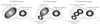 |
Fig. 8. Illustration of three suggested dynamical scenarios for the HZ10 system consistent with the kinematic modeling of [C II] emission and observational properties derived from rest-frame optical emission. |
6. Comparison with JWST/NIRSpec
Recent JWST/NIRSpec observations (with angular resolution of 0.15″ and resolving power of R ≈ 2700) support the complex morphology and kinematics of HZ10 (Jones et al. 2024). In Fig. 9 we show the morphological comparison between the [C II] components and those detected in [O III] 5007Å (top panel) and in Hα (bottom panel) with JWST/NIRSpec. The spatial positions of the [C II], [O III], and Hα components are in good agreement. As shown in Sect. 4, the HZ10-E component appears relatively dim in [C II] emission and can only be detected through its kinematic properties using, for example, PV diagrams (Figs. 4 and 6) or adaptive integrated intensity maps (Fig. 5). However, the spatial position of this component aligns well with one of the three components clearly revealed in rest-frame optical emission line intensity maps. This provides an independent confirmation of the reliability of the kinematically detected dim HZ10-E component in [C II] emission.
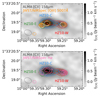 |
Fig. 9. Integrated [C II] intensity of the whole HZ10 complex in grayscale. To emphasize the spatial positions of the three components seen in [C II], HZ10-E, HZ10-C, and HZ10-W, we overplot contours from Fig. 5. The orange (pink) contours in the top (bottom) panel correspond to the [O III] 5007Å (Hα) relative contours from JWST/NIRSpec observations (Jones et al. 2024). Apertures for the components’ spectra (see Fig. 10) extraction are shown as white circles in the top panel. The beam size of the ALMA observations (0.34″ × 0.27″) and JWST/NIRSpec point spread function (0.15″) are shown in the bottom-left corner of each panel with a dashed gray ellipse and a solid orange (pink) circle, respectively. |
Since the spatial distribution of the [C II] emission resembles the rest-frame optical line emission from JWST/NIRSpec, we also aim to compare them in velocity space. Jones et al. (2024) reported the presence of narrow and broad spectral components for all three resolved systems: HZ10-E, HZ10-C, and HZ10-W. From a spaxel-by-spaxel analysis of [O III] 5007Å and Hα spectral profiles, Jones et al. (2024) showed that HZ10-W and HZ10-E mostly exhibit blue and red spectral profile asymmetry, respectively, while HZ10-C shows a gradient of red-to-blue asymmetry.
We extracted [C II] and [O III] 5007Å spectra from circular apertures with radii of 0.12″centered on the HZ10-E, HZ10-C, and HZ10-W components7 to compare their spectral properties; see Fig. 10. Given the lower spatial resolution of ALMA observations compared to those of JWST/NIRSpec, accounting for the blending of different spectral components from HZ10-C and HZ10-E becomes important during the analysis. To take this into account, we also show the [O III] spectra extracted from the JWST/NIRSpec data cube with the degraded spatial resolution to match that of ALMA (solid black curves in Fig. 10). In addition, we averaged the [C II] spectra to match the lower spectral resolution of [O III] data. We see from the aperture spectra that the velocity centroids and widths of the [C II] 158μm emission for all three HZ10 components are similar to those of the [O III] 5007Å emission.
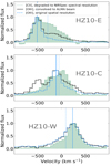 |
Fig. 10. [O III] 5007Å JWST/NIRSpec (black and dashed blue lines) and [C II] ALMA (green) spectra of the HZ10-E (top), HZ10-C (middle), and HZ10-W (bottom) components. The spectra were extracted from circular apertures that roughly match the beam size and were centered on the spatial positions of the components. For the JWST/NIRSpec spectra, the solid black line shows data from a cube with spatial resolution degraded to match that of ALMA, while the dashed blue line shows data at the original spatial resolution. For the ALMA data, the spectral resolution is degraded to match that of the [O III] data. Zero velocity is calculated at the systemic redshift z = 5.6548. The vertical solid and dotted blue lines indicate the velocity centroids of the narrow and broad rest-frame optical spectral line components, respectively, taken from Jones et al. (2024). Note that we renormalized all spectra to their peak intensity to simplify the kinematic comparison of the profiles; thus, the relative fluxes here are not comparable to the observed ones. However, we compare the observed fluxes in the main text. |
As a next step, we compared the [C II] velocity map with those of the narrow and broad components of [O III]. For this, we performed a spaxel-by-spaxel [O III] spectral fitting with single and double Gaussian profiles, taking into account the NIRSpec instrumental broadening.
Since the ALMA beam size exceeds the separation between the closest system components, we cannot perform the same spaxel-by-spaxel [C II] spectral fitting using a double Gaussian profile to search for a broad emission component. This is because the multicomponent Gaussian profile of the [C II] emission is dominated by beam smearing. However, we can test which [O III] line component, narrow or broad, more closely resembles the [C II] emission kinematics by comparing the [O III] velocity and dispersion maps with the [C II] moment-0 and moment-1 maps. For the direct comparison, we also re-binned the [C II] moment-0 and moment-1 maps to match the pixel size of the [O III] maps and applied the same spatial mask.
In Fig. 11 we show the corresponding [O III] velocity and dispersion maps derived from the best-fit spectral profiles, re-binned and masked [C II] moment-0 and moment-1 maps and velocity and velocity dispersion comparison maps. Zero velocity is calculated for the rest-frame [O III] or [C II] frequency at z = 5.6548. For the broad [O III] component maps and the velocity dispersion of the narrow [O III] component we only show the spaxels where the double Gaussian profile fit is preferred over the single Gaussian profile fit.
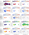 |
Fig. 11. From top to bottom: Spaxel-by-spaxel flux attributed to the narrow and broad [O III] emission and the corresponding flux ratio, [O III] (narrow and broad line emission component) and [C II] velocity and velocity dispersion maps and their respective comparison maps. Zero velocity corresponds to the rest-frame frequency at z = 5.6548 for all maps. The velocity dispersion of the narrow [O III] component in most of the spaxels is limited by the JWST/NIRSpec spectral resolution of R = 2700. |
In the top panel of Fig. 11 we also compare the [O III] flux attributed to the broad and narrow emission line components. The flux ratio between the narrow and broad [O III] line emission shows that the broad [O III] component, which could trace the outflows and/or tidal interactions, contributes significantly to the total [O III] flux of the HZ10 system. Furthermore, as seen from the spaxel-by-spaxel narrow to broad [O III] flux ratio, the narrow [O III] emission is surrounded by the broad [O III] emission. This effect is most noticeable in the case of HZ10-E. As expected, the velocity difference between the [O III] narrow and broad components reproduces the [O III] spectral line asymmetry map in Jones et al. (2024).
From the comparison of the [O III] and [C II] velocity maps, one can see that the velocity of the [O III] narrow emission line is significantly blue-shifted from the [C II] emission in the central spaxels of HZ10-C and for the entire HZ10-E component. The blue velocity shift for the HZ10-C component reflects the brightness asymmetry in the [C II] double-gaussian profile in the corresponding spaxels. On the other hand, the blue shift observed in the HZ10-E component has a more complicated nature and is caused by several factors. Firstly, the ALMA angular resolution leads to a blending of the different [C II] spectral components from HZ10-C and HZ10-E within the individual spaxels. Secondly, the weaker [C II] line emission from HZ10-E compared to HZ10-C elevates this effect resulting in a red shift of the intensity-weighted [C II] velocity of HZ10-E compared with that of the bright and spatially isolated from HZ10-C [O III] narrow emission.
7. Discussion
We have so far presented an analysis of the HZ10 system that includes kinematic modeling of the [C II] 158μm emission and comparison of the high spatial and spectral resolution ALMA [C II] observations with the rest-frame optical emission lines from JWST/NIRSpec. Our main findings are as follows:
(a) We find evidence of at least three [C II] emission components of the HZ10 system, which are consistent with those recently identified with JWST/NIRSpec rest-frame optical emission line observations.
(b) HZ10 is a complex system likely showing the ongoing merger between the [C II] bright HZ10-C+HZ10-E component and HZ10-W.
(c) The HZ10-C+HZ10-E system suggests three possible scenarios that are consistent with the currently available observations and modeling: (i) HZ10-C+HZ10-E is a disturbed galaxy disk, where HZ10-E is a fainter clump within the extended disk; (ii) HZ10-E is a satellite galaxy merging with the disk-like galaxy HZ10-C; (iii) HZ10-C+HZ10-E is triple merger where HZ10-C is itself a close double merger showing ongoing merging with the faint companion galaxy HZ10-E.
(d) The joint analysis of the [C II] and [O III] spectral profiles and velocity maps indicates that [C II] and broad [O III] emission kinematically trace each other.
Although [C II] emission can originate from various phases of the interstellar medium, including the ionized phase, both low-redshift observations and numerical simulations indicate that the majority of the total [C II] luminosity in galaxies is primarily produced in photodissociation regions (e.g., Pineda et al. 2013; Pallottini et al. 2017; Olsen et al. 2017). Based on modeling of the [C II] 158μm/[N II] 205μm ratio using the photoionization code Cloudy, Pavesi et al. (2016) estimated that only 10 − 25% of the observed [C II] emission in HZ10 originates from ionized gas. Although this estimate was made for the entire HZ10 system and could only be used for a resolved estimate of the individual components under strict assumptions, the similarity in kinematic properties of the integrated [C II] and [O III] line emission profiles across all three HZ10 components (Fig. 10) suggests that the neutral and ionized gas in this system trace similar kinematics and appear to be well mixed. Moreover, a spaxel-by-spaxel analysis shows that [C II] velocity and velocity dispersion are particularly similar to those of broad [O III] emission (see Fig. 11), which, as shown by Jones et al. (2024), trace ionized outflows and tidal interactions in HZ10. Therefore, the kinematic similarity of the [C II] and [O III] line emission points to an interacting nature of the HZ10 system, rather than a multiphase origin of the [C II] emission.
A recent joint analysis of JWST/NIRSpec and ALMA observations of another high-redshift clumpy merging system, HZ4, revealed a multiphase outflow detectable in [O III] 5007Å, Hα, and [C II] emission (Parlanti et al. 2025). While we do not detect outflow features in [C II] emission for HZ10, this is likely due to the limited angular resolution of the ALMA data and the close separation between system components.
While the kinematic properties of the [C II] emission for all three HZ10 components are similar to those of [O III], the flux line ratios, calculated in the apertures shown in Fig. 9, differ significantly: for HZ10-E [O III] 5007 Å/[C II] is ≳1.2, while for HZ10-C and HZ10-E this ratio is ∼0.5 and ∼0.6, respectively. Despite being the brightest component in the HZ10 system in [O III], HZ10-E is very dim in [C II].
Since the carbon abundance linearly depends on the metallicity, the decreased [C II] flux for the HZ10-E component can be explained by its relatively low metallicity among the entire HZ10 complex (Z/Z⊙ = 0.53 ± 0.09 in comparison with Z/Z⊙ = 0.64 ± 0.11 and 0.72 ± 0.12 for HZ10-C and HZ10-W; Jones et al. 2024). However, metallicity measurements based on JWST observations for all three components agree with each other within the provided uncertainties.
Studies in local galaxy clusters have shown that photoevaporation can complement the viscous stripping in removing the cold gas from galaxy disks (e.g., Bureau & Carignan 2002; Cortese et al. 2021; Villanueva et al. 2022, and references therein). This may drive lower [C II] fluxes and consequently higher [O III] 5007Å/[C II] 158μm flux ratio. Indeed, recent numerical simulations have shown that the photoevaporation of molecular clouds caused by intense UV radiation from nearby young massive stars can result in a high flux ratio between [O III] 88μm and [C II] 158μm (Vallini et al. 2017). However, according to simulations an increase in the [O III]/[C II] flux ratio in the far-infrared is particularly significant in the context of lower metallicity, specifically below a metallicity of about Z/Z⊙ ∼ 0.2, and not necessarily attributed to the increased [O III] 5007Å/[C II] 158μm flux ratio, which means that this scenario may only be tentatively applicable to HZ10-E.
Additionally, negative stellar feedback could in principle lead to an increased [O III]/[C II] flux ratio by clearing out gas around star-forming region (e.g., Ferrara et al. 2019). However, HZ10-E, on the contrary, exhibits a star-formation rate based on Hα similar to HZ10-C and HZ10-W (Jones et al. 2024).
Based on the JWST/NIRSpec data of HZ10, Jones et al. (2024) propose that HZ10-E is a separate galaxy, merging with HZ10-C and HZ10-W. Indeed, HZ10-E and HZ10-C show spatially distinct optical line emission peaks, slightly different metallicities, line flux ratios, color excess, and UV slopes, supporting scenarios (ii) and (iii). However, there are examples where galaxies exhibit metallicity gradients as well as inhomogeneous dust distribution (e.g., Miller et al. 2022; Rodríguez Del Pino et al. 2024). Therefore, even with the advent of JWST/NIRSpec data, we cannot rule out a scenario (i) in which HZ10-E and HZ10-C are clumps of an extended galaxy disk, thus keeping this scenario as favorable. However, since we cannot currently completely discard any of the three possible scenarios, ALMA observations with a higher angular resolution that matches that of JWST data but with a superior spectral resolution are necessary to distinguish between them.
8. Conclusions
We have presented a detailed kinematic analysis of the far-infrared-bright massive galaxy complex HZ10 at the end of the epoch of reionization at z ≈ 5.65. The study was based on the high-spatial- (≈0.3″ or 1.8 kpc at z = 5.65) and high-spectral-resolution observations of [C II] 158μm line emission with ALMA along with high-spatial-resolution observations (≈0.15″ or 0.9 kpc at z = 5.65) of the [O III] 5007Å line emission from JWST/NIRSpec. The new observations of the HZ10 system, previously classified as a massive main-sequence galaxy, revealed its complex morphological and kinematical nature, showing that HZ10 consists of at least three components in the close projected distance: HZ10-E, HZ10-C, and HZ10-W. The brightest component in [C II] line emission, HZ10-C (with the dim HZ10-E component in close separation), is characterized by complex kinematics and could be either a close merger or (more likely) a disturbed disk.
The high-angular-resolution JWST/NIRSpec data confirm the complex morphology of HZ10 observed with ALMA and show the broad component emission, which in turn indicates the presence of outflows and/or tidal interactions in the system (Jones et al. 2024). Moreover, the broad [O III] emission line component contributes significantly to the total [O III] flux of the HZ10 complex.
While ALMA and JWST provide insight into the cold molecular and ionized interstellar gas in early galaxies and trace star formation on different timescales, future deep integral-field Lyα observations would be key to reconstructing the interconnection between interstellar and circumgalactic gas. This is needed to characterize and disentangle the physical processes – outflows, inflows, and merger-induced shocks – occurring in overdensity environments. Thanks to available ALMA and JWST data, HZ10 was selected as a part of the ORigin of the [C II] Halos In Distant Systems (ORCHIDS) JWST Cycle 3 program 5974. This program aims to complement the rest-frame optical JWST/NIRSpec observations with those of dust and [C II] from ALMA and Lyα from Keck Cosmic Reionization Mapper (KCRM) to unveil the nature of [C II] halos at high redshifts. Furthermore, observations of diffuse stellar emission with JWST Mid-Infrared Instrument (MIRI), along with higher-spatial-resolution [C II] follow-up observations with ALMA, are needed to gain a more detailed view of the dynamical processes occurring in the close HZ10-E+HZ10-C system.
Seeking higher CO(5-4) and CO(6-5) transitions with the Northern Extended Millimeter Array (NOEMA) resulted in a non-detection for HZ10 (Vieira et al. 2022).
Pavesi et al. (2019) estimated gas mass from CO luminosity assuming a Galactic conversion factor, αCO, of ∼4.5.
We examined how different spatial (defined by noise levels estimated from the moment-0 map) and velocity (associated with HZ10-W component emission) masking affect the derived position angle of the major kinematic axis, and, consequently, the extracted rotation curves. We find that this effect remains minor and has little impact on the extracted rotation curves and DysmalPy kinematic modeling results.
Due to their close separation and weak emission from HZ10-E, HZ10-E and HZ10-C cannot be distinguished in the integrated [C II] map. As a result, these components were modeled as a single Sérsic profile, with the best-fit parameters listed in Table 1 under the HZ10-C column.
Although the aperture sizes are comparable to those used in Jones et al. (2024), the central position of the HZ10-W aperture differs due to a slight offset (less than the ALMA beam size) between the [C II] and [O III] emission peaks. To accurately capture the [C II] emission for spectral comparison, we shifted this aperture eastward from the [O III] emission peak.
Acknowledgments
K.T. was supported by ALMA ANID grant number 31220026 and by the ANID BASAL project FB210003. K.Tad. acknowledges support from JSPS KAKENHI grant No. 23K03466. A.F. acknowledges support from the ERC Advanced Grant INTERSTELLAR H2020/740120. H.Ü. acknowledges funding by the European Union (ERC APEX, 101164796). Views and opinions expressed are however those of the authors only and do not necessarily reflect those of the European Union or the European Research Council Executive Agency. Neither the European Union nor the granting authority can be held responsible for them. M.R. acknowledges support from projects PID2020-114414GB-100 and PID2023-150178NB-I00 financed by MCIN/AEI/10.13039/501100011033. I.D.L. acknowledges funding from the Belgian Science Policy Office (BELSPO) through the PRODEX project “JWST/MIRI Science exploitation” (C4000142239), from the European Research Council (ERC) under the European Union’s Horizon 2020 research and innovation programme DustOrigin (ERC-2019-StG-851622) and from the Flemish Fund for Scientific Research (FWO-Vlaanderen) through the research project G0A1523N. V.V. acknowledges support from the ALMA-ANID Postdoctoral Fellowship under the award ASTRO21-0062. R.J.A. was supported by FONDECYT grant number 1231718 and by the ANID BASAL project FB210003. R.I. is supported by Grants-in-Aid for Japan Society for the Promotion of Science (JSPS) Fellows (KAKENHI Grant Number 23KJ1006). I.L. acknowledges support from PRIN-MUR project “PROMETEUS” (202223XPZM). M.P. acknowledges support from the research project PID2021-127718NB-I00 of the Spanish Ministry of Science and Innovation/State Agency of Research (MCIN/AEI/10.13039/501100011033), and of the INAF Large Grant 2022 “The metal circle: a new sharp view of the baryon cycle up to Cosmic Dawn with the latest generation IFU facilities”. T.D.S. acknowledges the research project was supported by the Hellenic Foundation for Research and Innovation (HFRI) under the “2nd Call for HFRI Research Projects to support Faculty Members & Researchers” (Project Number: 3382). N.M.F.S. acknowledges funding by the European Union (ERC Advanced Grant GALPHYS, 101055023). Views and opinions expressed are, however, those of the author(s) only and do not necessarily reflect those of the European Union or the European Research Council. Neither the European Union nor the granting authority can be held responsible for them. This paper makes use of the following ALMA data: ADS/JAO.ALMA#2019.1.1075.S. ALMA is a partnership of ESO (representing its member states), NSF (USA) and NINS (Japan), together with NRC (Canada), NSTC and ASIAA (Taiwan), and KASI (Republic of Korea), in cooperation with the Republic of Chile. The Joint ALMA Observatory is operated by ESO, AUI/NRAO and NAOJ.
References
- Akins, H. B., Fujimoto, S., Finlator, K., et al. 2022, ApJ, 934, 64 [NASA ADS] [CrossRef] [Google Scholar]
- Bakx, T. J. L. C., Tamura, Y., Hashimoto, T., et al. 2020, MNRAS, 493, 4294 [NASA ADS] [CrossRef] [Google Scholar]
- Begum, A., Chengalur, J. N., Karachentsev, I. D., Sharina, M. E., & Kaisin, S. S. 2008, MNRAS, 386, 1667 [NASA ADS] [CrossRef] [Google Scholar]
- Bouwens, R. J., Smit, R., Schouws, S., et al. 2022, ApJ, 931, 160 [NASA ADS] [CrossRef] [Google Scholar]
- Bureau, M., & Carignan, C. 2002, AJ, 123, 1316 [NASA ADS] [CrossRef] [Google Scholar]
- Capak, P. L., Carilli, C., Jones, G., et al. 2015, Nature, 522, 455 [NASA ADS] [CrossRef] [Google Scholar]
- Chakraborty, A., & Roy, N. 2023, MNRAS, 519, 4074 [NASA ADS] [CrossRef] [Google Scholar]
- Cortese, L., Catinella, B., & Smith, R. 2021, PASA, 38, e035 [NASA ADS] [CrossRef] [Google Scholar]
- Cresci, G., Hicks, E. K. S., Genzel, R., et al. 2009, ApJ, 697, 115 [Google Scholar]
- Davies, R. I., Tacconi, L. J., & Genzel, R. 2004a, ApJ, 613, 781 [NASA ADS] [CrossRef] [Google Scholar]
- Davies, R. I., Tacconi, L. J., & Genzel, R. 2004b, ApJ, 602, 148 [NASA ADS] [CrossRef] [Google Scholar]
- Davies, R., Förster Schreiber, N. M., Cresci, G., et al. 2011, ApJ, 741, 69 [NASA ADS] [CrossRef] [Google Scholar]
- de Blok, W. J. G., Walter, F., Smith, J. D. T., et al. 2016, AJ, 152, 51 [NASA ADS] [CrossRef] [Google Scholar]
- de Blok, W. J. G., Healy, J., Maccagni, F. M., et al. 2024, A&A, 688, A109 [NASA ADS] [CrossRef] [EDP Sciences] [Google Scholar]
- Díaz-Santos, T., Assef, R. J., Blain, A. W., et al. 2018, Science, 362, 1034 [Google Scholar]
- Duncan, K., Conselice, C. J., Mundy, C., et al. 2019, ApJ, 876, 110 [NASA ADS] [CrossRef] [Google Scholar]
- Ferrara, A., Vallini, L., Pallottini, A., et al. 2019, MNRAS, 489, 1 [Google Scholar]
- Foreman-Mackey, D., Hogg, D. W., Lang, D., & Goodman, J. 2013, PASP, 125, 306 [Google Scholar]
- Fujimoto, S., Ouchi, M., Ferrara, A., et al. 2019, ApJ, 887, 107 [Google Scholar]
- Fujimoto, S., Silverman, J. D., Bethermin, M., et al. 2020, ApJ, 900, 1 [Google Scholar]
- Fujimoto, S., Ouchi, M., Nakajima, K., et al. 2024, ApJ, 964, 146 [NASA ADS] [CrossRef] [Google Scholar]
- Gaia Collaboration (Prusti, T., et al.) 2016, A&A, 595, A1 [NASA ADS] [CrossRef] [EDP Sciences] [Google Scholar]
- Gaia Collaboration (Brown, A. G. A., et al.) 2018, A&A, 616, A1 [NASA ADS] [CrossRef] [EDP Sciences] [Google Scholar]
- Gaia Collaboration (Brown, A. G. A., et al.) 2021, A&A, 649, A1 [NASA ADS] [CrossRef] [EDP Sciences] [Google Scholar]
- Ginolfi, M., Jones, G. C., Béthermin, M., et al. 2020, A&A, 643, A7 [NASA ADS] [CrossRef] [EDP Sciences] [Google Scholar]
- Goldsmith, P. F., Langer, W. D., Pineda, J. L., & Velusamy, T. 2012, ApJS, 203, 13 [Google Scholar]
- Guaita, L., Aravena, M., Gurung-Lopez, S., et al. 2022, A&A, 660, A137 [NASA ADS] [CrossRef] [EDP Sciences] [Google Scholar]
- Herrera-Camus, R., Förster Schreiber, N. M., Price, S. H., et al. 2022, A&A, 665, L8 [NASA ADS] [CrossRef] [EDP Sciences] [Google Scholar]
- Herrera-Camus, R., González-López, J., Förster Schreiber, N., et al. 2025, A&A, in press, https://doi.org/10.1051/0004-6361/202553896 [Google Scholar]
- Hoffmann, S. L., Mack, J., Avila, R., et al. 2021, Am. Astron. Soc. Meeting Abstr., 53, 21602 [Google Scholar]
- Hunter, D. A., Ficut-Vicas, D., Ashley, T., et al. 2012, AJ, 144, 134 [CrossRef] [Google Scholar]
- Ikeda, R., Tadaki, K.-I., Mitsuhashi, I., et al. 2025, A&A, 693, A237 [NASA ADS] [CrossRef] [EDP Sciences] [Google Scholar]
- Jones, G. C., Vergani, D., Romano, M., et al. 2021, MNRAS, 507, 3540 [NASA ADS] [CrossRef] [Google Scholar]
- Jones, G. C., Bunker, A. J., Telikova, K., et al. 2024, MNRAS, submitted, [arXiv:2405.12955] [Google Scholar]
- Jorsater, S., & van Moorsel, G. A. 1995, AJ, 110, 2037 [Google Scholar]
- Kohandel, M., Pallottini, A., Ferrara, A., et al. 2019, MNRAS, 487, 3007 [NASA ADS] [CrossRef] [Google Scholar]
- Kohandel, M., Pallottini, A., Ferrara, A., et al. 2024, A&A, 685, A72 [NASA ADS] [CrossRef] [EDP Sciences] [Google Scholar]
- Lang, P., Förster Schreiber, N. M., Genzel, R., et al. 2017, ApJ, 840, 92 [NASA ADS] [CrossRef] [Google Scholar]
- Lee, L. L., Förster Schreiber, N. M., Price, S. H., et al. 2025, ApJ, 978, 14 [Google Scholar]
- Le Fèvre, O., Béthermin, M., Faisst, A., et al. 2020, A&A, 643, A1 [Google Scholar]
- Lewis, A. J. R., Ivison, R. J., Best, P. N., et al. 2018, ApJ, 862, 96 [NASA ADS] [CrossRef] [Google Scholar]
- Mallery, R. P., Mobasher, B., Capak, P., et al. 2012, ApJ, 760, 128 [NASA ADS] [CrossRef] [Google Scholar]
- Markov, V., Carniani, S., Vallini, L., et al. 2022, A&A, 663, A172 [NASA ADS] [CrossRef] [EDP Sciences] [Google Scholar]
- Miller, T. B., Whitaker, K. E., Nelson, E. J., et al. 2022, ApJ, 941, L37 [NASA ADS] [CrossRef] [Google Scholar]
- Mitsuhashi, I., Tadaki, K.-I., Ikeda, R., et al. 2024, A&A, 690, A197 [NASA ADS] [CrossRef] [EDP Sciences] [Google Scholar]
- Murayama, T., Taniguchi, Y., Scoville, N. Z., et al. 2007, ApJS, 172, 523 [NASA ADS] [CrossRef] [Google Scholar]
- Navarro, J. F., Frenk, C. S., & White, S. D. M. 1996, ApJ, 462, 563 [Google Scholar]
- Neeleman, M., Walter, F., Decarli, R., et al. 2023, ApJ, 958, 132 [NASA ADS] [CrossRef] [Google Scholar]
- Nightingale, J. W., Hayes, R. G., & Griffiths, M. 2021, J. Open Source Softw., 6, 2550 [NASA ADS] [CrossRef] [Google Scholar]
- Nightingale, J. W., Amvrosiadis, A., Hayes, R. G., et al. 2023, J. Open Source Softw., 8, 4475 [Google Scholar]
- Olsen, K., Greve, T. R., Narayanan, D., et al. 2017, ApJ, 846, 105 [Google Scholar]
- Oteo, I., Ivison, R. J., Dunne, L., et al. 2018, ApJ, 856, 72 [Google Scholar]
- Overzier, R. A. 2016, A&A Rev., 24, 14 [NASA ADS] [CrossRef] [Google Scholar]
- Pallottini, A., Ferrara, A., Gallerani, S., et al. 2017, MNRAS, 465, 2540 [CrossRef] [Google Scholar]
- Parlanti, E., Carniani, S., Venturi, G., et al. 2025, A&A, 695, A6 [NASA ADS] [CrossRef] [EDP Sciences] [Google Scholar]
- Patra, N. N., Chengalur, J. N., Karachentsev, I. D., & Sharina, M. E. 2016, Astrophys. Bull., 71, 408 [Google Scholar]
- Pavesi, R., Riechers, D. A., Capak, P. L., et al. 2016, ApJ, 832, 151 [Google Scholar]
- Pavesi, R., Riechers, D. A., Sharon, C. E., et al. 2018, ApJ, 861, 43 [Google Scholar]
- Pavesi, R., Riechers, D. A., Faisst, A. L., Stacey, G. J., & Capak, P. L. 2019, ApJ, 882, 168 [Google Scholar]
- Pineda, J. L., Langer, W. D., Velusamy, T., & Goldsmith, P. F. 2013, A&A, 554, A103 [CrossRef] [EDP Sciences] [Google Scholar]
- Pizzati, E., Ferrara, A., Pallottini, A., et al. 2020, MNRAS, 495, 160 [Google Scholar]
- Posses, A. C., Aravena, M., González-López, J., et al. 2023, A&A, 669, A46 [NASA ADS] [CrossRef] [EDP Sciences] [Google Scholar]
- Posses, A., Aravena, M., González-López, J., et al. 2025, A&A, in press, https://doi.org/10.1051/0004-6361/202449843 [Google Scholar]
- Price, S. H., Shimizu, T. T., Genzel, R., et al. 2021, ApJ, 922, 143 [NASA ADS] [CrossRef] [Google Scholar]
- Rizzo, F., Kohandel, M., Pallottini, A., et al. 2022, A&A, 667, A5 [NASA ADS] [CrossRef] [EDP Sciences] [Google Scholar]
- Rizzo, F., Roman-Oliveira, F., Fraternali, F., et al. 2023, A&A, 679, A129 [NASA ADS] [CrossRef] [EDP Sciences] [Google Scholar]
- Rizzo, F., Bacchini, C., Kohandel, M., et al. 2024, A&A, 689, A273 [NASA ADS] [CrossRef] [EDP Sciences] [Google Scholar]
- Rodríguez Del Pino, B., Perna, M., Arribas, S., et al. 2024, A&A, 684, A187 [NASA ADS] [CrossRef] [EDP Sciences] [Google Scholar]
- Romano, M., Cassata, P., Morselli, L., et al. 2021, A&A, 653, A111 [NASA ADS] [CrossRef] [EDP Sciences] [Google Scholar]
- Rowland, L. E., Hodge, J., Bouwens, R., et al. 2024, MNRAS, 535, 2068 [Google Scholar]
- Smit, R., Bouwens, R. J., Carniani, S., et al. 2018, Nature, 553, 178 [Google Scholar]
- Solimano, M., González-López, J., Aravena, M., et al. 2024, A&A, 689, A145 [NASA ADS] [CrossRef] [EDP Sciences] [Google Scholar]
- Solimano, M., González-López, J., Aravena, M., et al. 2025, A&A, 693, A70 [NASA ADS] [CrossRef] [EDP Sciences] [Google Scholar]
- Staveley-Smith, L., & Oosterloo, T. 2015, in Advancing Astrophysics with the Square Kilometre Array (AASKA14), 167 [CrossRef] [Google Scholar]
- Vallini, L., Ferrara, A., Pallottini, A., & Gallerani, S. 2017, MNRAS, 467, 1300 [NASA ADS] [Google Scholar]
- Vieira, D., Riechers, D. A., Pavesi, R., et al. 2022, ApJ, 925, 174 [NASA ADS] [CrossRef] [Google Scholar]
- Villanueva, V., Bolatto, A. D., Vogel, S., et al. 2022, ApJ, 940, 176 [NASA ADS] [CrossRef] [Google Scholar]
- Villanueva, V., Herrera-Camus, R., González-López, J., et al. 2024, A&A, 691, A133 [NASA ADS] [CrossRef] [EDP Sciences] [Google Scholar]
- Walter, F., Brinks, E., de Blok, W. J. G., et al. 2008, AJ, 136, 2563 [Google Scholar]
- Wuyts, S., Förster Schreiber, N. M., Wisnioski, E., et al. 2016, ApJ, 831, 149 [Google Scholar]
- Xi, H., Peng, B., Staveley-Smith, L., et al. 2024, ApJ, 966, L36 [NASA ADS] [Google Scholar]
Appendix A: Morphological 2D parametric modeling
We performed parametric 2D modeling of the [C II] moment-0 map with a two-component Sérsic profile using PyAutoGalaxy software. We followed the same steps as the 2D modeling of the HZ10 system presented in Villanueva et al. (2024). The result of the modeling, along with the residuals between the observations and the model, are shown in Fig. A.1.
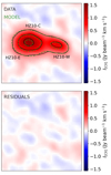 |
Fig. A.1. Top: [C II] integrated intensity (color map) and 5σ, 10σ, and 15σ noise levels (black contours). The best-fit two-component 2D Sérsic profile model is shown with dashed green 5σ, 10σ, and 15σ contours (see Table 1 for the parameter details). Bottom: Residuals between the observed intensity map and the best-fit 2D Sérsic profile. |
Appendix B: Aperture spectra fit
We calculated the rotation curve of the HZ10-C+HZ10-E complex by extracting [C II] spectra along its major axis using circular apertures with a diameter of 0.26″(solid green regions on the moment-0 map in Fig. 2). The corresponding aperture spectra are shown in Fig. B.1. We fit the extracted spectra with single and double Gaussian profiles to calculate velocity centroids and velocity dispersion in each aperture. In cases where the double-component profile fitting effectively results in a single-component solution (i.e., one of the components is poorly constrained), we used only a single-Gaussian model fit. The resulting fit profiles are shown in the same figure. Although we performed both single and double Gaussian profile fits, our focus was on the single Gaussian fit since we were aiming to model the rotation curves using DysmalPy. DysmalPy is specifically designed to account for observational effects such as beam smearing. As a result, the aperture spectra extracted from the mock cube also exhibit asymmetrical profiles, which are further analyzed using single Gaussian fits. However, the authors conclude that the 1D approach is just as effective as the 2D approach (which uses moment maps for comparison between model and observations) and the 3D approach (where observed and mock cubes are directly compared; Lee et al. 2025).
As an additional test, we also separated our the HZ10-C spectral component for an independent kinematic analysis with DysmalPy. For that, we modeled the contribution from HZ10-E to the total spectra in the first three apertures using a Gaussian profile. We show the corresponding spectral fits in Fig. B.2.
To further investigate whether the use of partly overlapping apertures introduces significant bias in the derived kinematic parameters, we repeated the same analysis using independent apertures of the same size. The resulting spectra and fit profiles are shown in Fig. B.3.
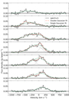 |
Fig. B.1. HZ10-E+HZ10-C aperture [C II] emission line spectra (black solid) and single (green dashed) or double (dash-dotted red) Gaussian fit profiles. When the double Gaussian fit is performed, the dotted gray curves show the individual components. The spectra (arranged from top to bottom) are extracted from the solid green regions in the moment-0 map in Fig. 2, displayed from left to right. |
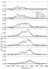 |
Fig. B.2. HZ10-E+HZ10-C aperture [C II] emission line spectra (black solid) and single Gaussian fit profiles (green dashed) attributed to HZ10-C. The spectra (arranged from top to bottom) are extracted from the solid green regions in the moment-0 map in Fig. 2, displayed from left to right. The contribution from HZ10-E in the first three apertures is shown by the dotted red Gaussian profile. |
Appendix C: DysmalPy kinematic modeling
In Fig. C.1 we show the velocity centroids and velocity dispersion extracted along the major kinematic axis of HZ10-E+HZ10-C using independent apertures. The modeled rotation curves are overlaid in the same figure. The 1D and 2D marginalized posterior distributions of the model parameters for HZ10-E+HZ10-C system for overlapping and independent apertures are shown in Fig. C.2. Circular velocity as a function of radius based on the best-fit results is shown in Fig. C.3. We find that the use of the independent and partly overlapping apertures for rotation curve extraction yields consistent results for the HZ10-E+HZ10-C system. We also show observed and best-fit rotation curves and 1D and 2D marginalized posterior distributions of the model parameters for the HZ10-C component alone after separating it from HZ10-E in Figs. C.4 and C.5.
 |
Fig. C.1. Rotation curves calculated along the major axis of the HZ10-E+HZ10-C complex using independent apertures. Data points correspond to the velocity centroids (left panel) and velocity dispersion (right panel) of a single (green squares) and double (blue and red crosses) Gaussian fit of the spectra within the circular apertures of radius 0.13″ as a function of the relative aperture position. Apertures were placed along the major axis with a step of 0.26″. Zero velocity is calculated for the rest-frame [C II] frequency at z = 5.6548. Zero offset corresponds to the aperture position at the same zero point as for the respective PV diagram. Aperture positions where the HZ10-E component impacts the spectra are shown with shading. Black curves represent the best-fit disk model from DysmalPy analysis. Normalized residuals represent the difference between data points and the model, divided by the data uncertainties. |
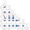 |
Fig. C.2. Posterior distributions of the estimated parameters for HZ10-E+HZ10-C system. Red and blue correspond to the analyses conducted with overlapping and independent apertures, respectively. Contours correspond to the 68 and 75 percent highest posterior density credible regions, respectively. Vertical dotted lines show 0.5 quantiles of the posterior distributions (overlapping apertures). |
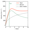 |
Fig. C.3. Best-fit results of DysmalPy kinematic modeling of HZ10-C+HZ10-E rotation curves. The solid red curve shows the total intrinsic circular velocity corrected by inclination and beam smearing. The baryon and dark matter components are shown with the dashed green and dotted black curves, respectively. The vertical green line corresponds to the disk’s effective radius. |
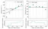 |
Fig. C.4. Rotation curves calculated for HZ10-C excluding the impact of the HZ10-E component. Data points correspond to the velocity centroids (left panel) and velocity dispersion (right panel) of a single Gaussian fit of the spectra within circular apertures of radius 0.13″ as a function of the relative aperture position. Apertures were placed along the major axis with a step of 0.13″. Zero velocity is calculated for the rest-frame [C II] frequency at z = 5.6548. Zero offset corresponds to the aperture position at the same zero point as for the respective PV diagram. Black curves represent the best-fit disk model done with DysmalPy. Normalized residuals represent the difference between data points and the model, divided by the data uncertainties. Note that we exclude the first aperture (top panel in Fig. B.2) as the emission in that region is dominated by the HZ10-E component. |
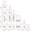 |
Fig. C.5. Posterior distributions of the estimated parameters for the HZ10-C system. Contours correspond to the 68 and 75 percent highest posterior density credible regions, respectively. Vertical dotted lines show 0.16, 0.5, and 0.84 quantiles of the posterior distributions. |
All Tables
All Figures
|
Fig. 1. HST WFC3/F105W image of HZ10 in grayscale with black 3σ contours. Panel A: [C II] 158 μm integrated intensity of HZ10 shown with red 5σ, 10σ, and 15σ contours. Panel B: 158 μm continuum of HZ10 shown with blue 3σ, 5σ, and 7σ contours. The beam size of the ALMA observations is shown with an ellipse in the bottom-left corner of each panel. |
| In the text | |
|
Fig. 2. [C II] integrated intensity (moment-0; top left panel), line-of-sight velocity (moment-1; zero velocity is a systemic velocity that corresponds to the rest-frame [C II] frequency at z = 5.6548; top-right panel), adopted line-of-sight velocity (where zero velocity corresponds to the HZ10-C systemic velocity; bottom-left panel), and velocity dispersion (moment-2; bottom-right panel) maps of HZ10. Contours correspond to the 2σ, 3σ, 5σ, 10σ, and 15σ noise levels estimated from the corresponding moment-0 map. The dashed and solid green regions on the moment-0 map correspond to the apertures for the spectra extraction. The dashed gray and dotted pink lines on the moment-1 maps correspond to the axes for the PV diagram calculations. The center of the main and major axes of HZ10 are indicated with the pink vertical line and the gray cross, respectively. An ellipse shows the beam size of the ALMA observations in the bottom-left corner of each panel. |
| In the text | |
|
Fig. 3. [C II] spectrum of HZ10 complex, extracted from the elliptical aperture, shown on the left panel of Fig. 2. Zero velocity corresponds to the rest-frame [C II] frequency at z = 5.6548. |
| In the text | |
|
Fig. 4. PV diagram calculated along the pseudo slit of 10-pixel width placed along the main axis in Fig. 2. Smoothed gray contours correspond to the 3σ, 5σ, 7σ, and 10σ noise levels. Zero velocity is calculated for the rest-frame [C II] frequency at z = 5.6548. |
| In the text | |
|
Fig. 5. Integrated [C II] intensity calculated within specific velocity ranges, defined from the PV diagram along the main axis of the HZ10 complex. Contours correspond to the 10σ and 15σ noise levels of the corresponding moment-0 maps. The beam size of the ALMA observations is shown with the green ellipse at the bottom-left corner of each panel. |
| In the text | |
|
Fig. 6. PV diagrams calculated using a pseudo slit of 10-pixel width placed along the major (top panel) and minor (bottom panel) axes of the HZ10-C+HZ10-E complex. Zero velocity is calculated for the rest-frame [C II] frequency at z = 5.6548. Smoothed gray contours correspond to the 3σ, 5σ, 7σ, and 9σ noise levels of the PV diagrams. |
| In the text | |
|
Fig. 7. Rotation curves calculated along the major axis of the HZ10-E+HZ10-C complex. Data points correspond to the velocity centroids (left panel) and velocity dispersion (right panel) of a single (green squares) and double (blue and red crosses) Gaussian fit of the spectra within the circular apertures of radius 0.13″ as a function of the relative aperture position. Apertures were placed along the major axis with a step of 0.13″. Zero velocity is calculated for the rest-frame [C II] frequency at z = 5.6548. Zero offset corresponds to the aperture position at the same zero point as for the respective PV diagram. Aperture positions where the HZ10-E component impacts the spectra are shown with shading. Black curves represent the best-fit disk model from DysmalPy analysis. Normalized residuals represent the difference between data points and the model, divided by the data uncertainties. |
| In the text | |
|
Fig. 8. Illustration of three suggested dynamical scenarios for the HZ10 system consistent with the kinematic modeling of [C II] emission and observational properties derived from rest-frame optical emission. |
| In the text | |
|
Fig. 9. Integrated [C II] intensity of the whole HZ10 complex in grayscale. To emphasize the spatial positions of the three components seen in [C II], HZ10-E, HZ10-C, and HZ10-W, we overplot contours from Fig. 5. The orange (pink) contours in the top (bottom) panel correspond to the [O III] 5007Å (Hα) relative contours from JWST/NIRSpec observations (Jones et al. 2024). Apertures for the components’ spectra (see Fig. 10) extraction are shown as white circles in the top panel. The beam size of the ALMA observations (0.34″ × 0.27″) and JWST/NIRSpec point spread function (0.15″) are shown in the bottom-left corner of each panel with a dashed gray ellipse and a solid orange (pink) circle, respectively. |
| In the text | |
|
Fig. 10. [O III] 5007Å JWST/NIRSpec (black and dashed blue lines) and [C II] ALMA (green) spectra of the HZ10-E (top), HZ10-C (middle), and HZ10-W (bottom) components. The spectra were extracted from circular apertures that roughly match the beam size and were centered on the spatial positions of the components. For the JWST/NIRSpec spectra, the solid black line shows data from a cube with spatial resolution degraded to match that of ALMA, while the dashed blue line shows data at the original spatial resolution. For the ALMA data, the spectral resolution is degraded to match that of the [O III] data. Zero velocity is calculated at the systemic redshift z = 5.6548. The vertical solid and dotted blue lines indicate the velocity centroids of the narrow and broad rest-frame optical spectral line components, respectively, taken from Jones et al. (2024). Note that we renormalized all spectra to their peak intensity to simplify the kinematic comparison of the profiles; thus, the relative fluxes here are not comparable to the observed ones. However, we compare the observed fluxes in the main text. |
| In the text | |
|
Fig. 11. From top to bottom: Spaxel-by-spaxel flux attributed to the narrow and broad [O III] emission and the corresponding flux ratio, [O III] (narrow and broad line emission component) and [C II] velocity and velocity dispersion maps and their respective comparison maps. Zero velocity corresponds to the rest-frame frequency at z = 5.6548 for all maps. The velocity dispersion of the narrow [O III] component in most of the spaxels is limited by the JWST/NIRSpec spectral resolution of R = 2700. |
| In the text | |
|
Fig. A.1. Top: [C II] integrated intensity (color map) and 5σ, 10σ, and 15σ noise levels (black contours). The best-fit two-component 2D Sérsic profile model is shown with dashed green 5σ, 10σ, and 15σ contours (see Table 1 for the parameter details). Bottom: Residuals between the observed intensity map and the best-fit 2D Sérsic profile. |
| In the text | |
|
Fig. B.1. HZ10-E+HZ10-C aperture [C II] emission line spectra (black solid) and single (green dashed) or double (dash-dotted red) Gaussian fit profiles. When the double Gaussian fit is performed, the dotted gray curves show the individual components. The spectra (arranged from top to bottom) are extracted from the solid green regions in the moment-0 map in Fig. 2, displayed from left to right. |
| In the text | |
|
Fig. B.2. HZ10-E+HZ10-C aperture [C II] emission line spectra (black solid) and single Gaussian fit profiles (green dashed) attributed to HZ10-C. The spectra (arranged from top to bottom) are extracted from the solid green regions in the moment-0 map in Fig. 2, displayed from left to right. The contribution from HZ10-E in the first three apertures is shown by the dotted red Gaussian profile. |
| In the text | |
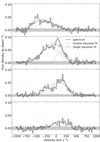 |
Fig. B.3. Same as Fig. B.1 but for independent apertures along the major axis. |
| In the text | |
|
Fig. C.1. Rotation curves calculated along the major axis of the HZ10-E+HZ10-C complex using independent apertures. Data points correspond to the velocity centroids (left panel) and velocity dispersion (right panel) of a single (green squares) and double (blue and red crosses) Gaussian fit of the spectra within the circular apertures of radius 0.13″ as a function of the relative aperture position. Apertures were placed along the major axis with a step of 0.26″. Zero velocity is calculated for the rest-frame [C II] frequency at z = 5.6548. Zero offset corresponds to the aperture position at the same zero point as for the respective PV diagram. Aperture positions where the HZ10-E component impacts the spectra are shown with shading. Black curves represent the best-fit disk model from DysmalPy analysis. Normalized residuals represent the difference between data points and the model, divided by the data uncertainties. |
| In the text | |
|
Fig. C.2. Posterior distributions of the estimated parameters for HZ10-E+HZ10-C system. Red and blue correspond to the analyses conducted with overlapping and independent apertures, respectively. Contours correspond to the 68 and 75 percent highest posterior density credible regions, respectively. Vertical dotted lines show 0.5 quantiles of the posterior distributions (overlapping apertures). |
| In the text | |
|
Fig. C.3. Best-fit results of DysmalPy kinematic modeling of HZ10-C+HZ10-E rotation curves. The solid red curve shows the total intrinsic circular velocity corrected by inclination and beam smearing. The baryon and dark matter components are shown with the dashed green and dotted black curves, respectively. The vertical green line corresponds to the disk’s effective radius. |
| In the text | |
|
Fig. C.4. Rotation curves calculated for HZ10-C excluding the impact of the HZ10-E component. Data points correspond to the velocity centroids (left panel) and velocity dispersion (right panel) of a single Gaussian fit of the spectra within circular apertures of radius 0.13″ as a function of the relative aperture position. Apertures were placed along the major axis with a step of 0.13″. Zero velocity is calculated for the rest-frame [C II] frequency at z = 5.6548. Zero offset corresponds to the aperture position at the same zero point as for the respective PV diagram. Black curves represent the best-fit disk model done with DysmalPy. Normalized residuals represent the difference between data points and the model, divided by the data uncertainties. Note that we exclude the first aperture (top panel in Fig. B.2) as the emission in that region is dominated by the HZ10-E component. |
| In the text | |
|
Fig. C.5. Posterior distributions of the estimated parameters for the HZ10-C system. Contours correspond to the 68 and 75 percent highest posterior density credible regions, respectively. Vertical dotted lines show 0.16, 0.5, and 0.84 quantiles of the posterior distributions. |
| In the text | |
Current usage metrics show cumulative count of Article Views (full-text article views including HTML views, PDF and ePub downloads, according to the available data) and Abstracts Views on Vision4Press platform.
Data correspond to usage on the plateform after 2015. The current usage metrics is available 48-96 hours after online publication and is updated daily on week days.
Initial download of the metrics may take a while.