| Issue |
A&A
Volume 697, May 2025
|
|
|---|---|---|
| Article Number | A42 | |
| Number of page(s) | 17 | |
| Section | Interstellar and circumstellar matter | |
| DOI | https://doi.org/10.1051/0004-6361/202554033 | |
| Published online | 05 May 2025 | |
Cosmic rays, gas, and dust in the central molecular zone
I. XCO factors, cosmic-ray densities, and dust opacities
1 Max-Planck-Institut für Kernphysik,
PO Box 103980,
69029
Heidelberg,
Germany
2 Université de Paris Cité, CNRS,
Astroparticule et Cosmologie,
75013
Paris,
France
3 Department for Physics and Technology, University of Bergen,
Allegaten 55,
Bergen
5020,
Norway
★ Corresponding authors: This email address is being protected from spambots. You need JavaScript enabled to view it.
; This email address is being protected from spambots. You need JavaScript enabled to view it.
Received:
4
February
2025
Accepted:
14
March
2025
Abstract
Context. The central molecular zone (CMZ) is a unique environment in our Galaxy, with extreme conditions to test our understanding of the gas, dust, and cosmic-ray (CR) physics.
Aims. Our goal is to estimate the total gas mass in the direction of the Galactic centre (GC), quantify the various associated uncertainties, and discuss the implications for the estimates of CR energy densities and dust opacities.
Methods. The HI 21 cm line and the carbon monoxide isotopes (12CO (J = 1 → 0), 13CO (J = 1 → 0; J = 2 → 1), and C18O (J = 2 → 1)) line emission maps were used to derive the total gas column density. The gas in the CMZ is separated from the disk contribution in position and velocity thanks to its different properties in terms of the velocity dispersion and brightness ratio of CO isotopes. The variations of the XCO factors were modelled relying on both theoretical trends from simulations and empirical corrections. We used the new gas column density estimated together with gamma-ray and dust emission measurements to derive the CR energy density and dust opacities, respectively.
Results. The XCO values in the CMZ range from (0.32–1.37) × 1020 cm−2 K−1 km−1 s, with a distribution that is highly asymmetric and skewed. The median value is X̅COCMZ = 0.39 × 1020 cm−2 K−1 km−1 s. The total gas mass in the CMZ is estimated to be 2.3−0.3+0.3 × 10⁷ M⊙ with an ∼10% contribution from the atomic phase. Without removing the disk contamination, the total mass is about twi-ce as higher, and the atomic gas fraction increases to ∼30%. The CR energy density in the CMZ, assuming a 1/r profile, is higher by a factor of two compared to the previous calculations at TeV energies.
Conclusions. Towards the GC the contamination from both atomic and molecular gas in the disk is not negligible. Using molecular gas tracers, which probes only the densest molecular cores, leads to an overestimation of the CR energy density, while ignoring the foreground and background contribution leads to an underestimation of the CR energy density in the CMZ.
Key words: ISM: clouds – cosmic rays – dust, extinction / ISM: lines and bands / ISM: structure / Galaxy: center
© The Authors 2025
 Open Access article, published by EDP Sciences, under the terms of the Creative Commons Attribution License (https://creativecommons.org/licenses/by/4.0), which permits unrestricted use, distribution, and reproduction in any medium, provided the original work is properly cited.
This article is published in open access under the Subscribe to Open model.
Open Access funding provided by Max Planck Society.
1 Introduction
The central molecular zone (CMZ) in the Galactic centre (GC) is an extreme environment, unlike any other region in the Galactic disk (see Table 2 of Henshaw et al. 2023, and references therein for an overview). It extends up to ∼250 pc in positive longitudes and ∼150 pc in negative ones (Ferrière et al. 2007). This region concentrates a very large fraction of dense molecular gas (>103cm−3), the kinematic temperature of the gas is five to ten times higher than in the disk (Guesten et al. 1985; Ginsburg et al. 2016), the clouds have high turbulent velocities (Bally et al. 1987; Morris & Serabyn 1996), and the majority of stars have super-solar metallicity (Do et al. 2015; Nandakumar et al. 2018; Schultheis et al. 2019). Characterising the properties of the various gas tracers in this environment is important to estimate the quantity of gas precisely.
Although H2 is the most abundant molecule in the Universe, it is very difficult to detect (Wakelam et al. 2017; Shull 2022). Therefore, many surveys of the molecular gas in the CMZ use other molecules as tracers of H2. These include the different line transitions of CO isotopologues, which probe most of the gas, HCN or CS for the densest cores, and many of the other rarer molecular species (see Mills 2017, and references therein). However, integrating observations from different molecular tracers, each with varying sensitivities, coverage, and angular resolution, into a single coherent model of the gas in the CMZ is challenging.
The estimate of gas column densities and mass is affected by a number of uncertainties and unknowns. Regarding the molecular phase, the main challenges are to determine up to which density range the CO emission traces the H2 gas reliably, and to characterise the variations of XCO, the CO-to-H2 conversion factor. XCO varies within a cloud and from cloud to cloud at parsec scales (Ripple et al. 2013; Remy et al. 2017; Kohno & Sofue 2024), but also across galaxies from their centres (Israel 2020; Teng et al. 2023) to kilo-parsec scales (Arimoto et al. 1996; Sandstrom et al. 2013). These variations can be modelled as a function of the properties of the environment and the resolved scale (Bell et al. 2006; Glover & Mac Low 2011; Bertram et al. 2016; Gong et al. 2020) but insights from simulations are not straightforward to compare with observations. Valuable information can be gained considering multiple molecular gas tracers. However there is no clear recipe on how to combine them in order to probe a wider range of densities, on the one hand in the densest core where CO emission saturates (Dahmen et al. 1998), and on the other hand at the transition between atomic and molecular phases where CO surveys lack sensitivity to detect diffuse H2 (Grenier et al. 2005; Liszt & Gerin 2023). Regarding the atomic phase traced by the neutral hydrogen, HI, the main sources of uncertainties are the impact of the HI self-absorption (Pohl et al. 2022) and the value of the HI spin temperature (Sofue 2017).
If one tries to estimate the quantity of gas from observations of dust emission, other questions arise. One can ask how well the dust is mixed with the gas. This requires to determine on which spatial scales the dust-to-gas mass ratio varies and by how much (Liseau et al. 2015; Tricco et al. 2017). One can also ask how the dust emission properties change as the dust grains evolve in different environments, or as the dust temperature varies along the line of sight, and how does this affect the estimate of the dust mass (Planck Collaboration XI 2014; Köhler et al. 2015; Ysard et al. 2019, 2024).
Rather than detailing all these questions here, we are going to start by extracting one conclusion: in order to estimate the gas column densities properly, not only does one have to rely on multiple independent tracers, taking into account the variations of their various properties and conversion factors with the environment, but also to take into account the variations with the sensitivity and resolved scale of the observations. As this is not straightforward to apply in data analysis, simpler approaches relying on single tracers and generic constant conversion factors are still used, especially outside the interstellar medium community, as in very-high-energy γ-ray astronomy.
For example, the H.E.S.S. Collaboration (2018) shows that the γ-ray emission seen by the High Energy Stereoscopic System (H.E.S.S.) in the CMZ is correlated with dense gas traced by CS molecules and that its flux is about half the total diffuse emission flux in the region. Still, the large-scale diffuse component was derived from an empirical model and not based on a gas template. Earlier studies by Dahmen et al. (1998) showed that the diffuse gas component traced by 12CO, outside of the dense cores where C18O is detected, accounts for up to half of the total mass. Therefore, the more diffuse regions can contain as much gas as the denser and cooler cloud cores. Then, the large scale diffuse emission seen in γ-ray by H.E.S.S. towards the GC could also arise from hadronic collisions of cosmic rays (CRs) in less dense regions of the interstellar medium (ISM). Another study of the GC by H.E.S.S. Collaboration (2016) considered CO, CS, and HCN as alternative tracers. Still, they have not attempted to combine them to probe a larger range of gas density, and cloud to cloud variations of the conversion factors to molecular hydrogen have not been considered so far. Even in the recent study by MAGIC Collaboration (2020), only CS emission was considered as s gas tracer. Still, nowadays, the lack of a reliable total gas column density model and a clear view of the associated uncertainties is a limiting factor for the γ-ray studies on the CR density profile towards the GC, the base of the Fermi-bubbles, or a potential dark matter excess.
In this paper, we produce a map of the total hydrogen column density, NH, in the CMZ combining HI data and a set of CO isotopologue observations. We also aim to quantify the various uncertainties inherent to the exercise. The final products are, in particular, meant to be used in future γ-ray studies of the GC. The data used are listed in Sect. 2. The method is summarised as follows: the HI and CO velocity profiles are decomposed into a collection of lines (Sect. 3.1); the properties of the lines are used to separate the CMZ from the gas in the disk (Sect. 3.2); relying on both the theoretical trend from simulations and the empirical corrections we derive XCO factors for each line such as we minimise the variance of NH2 obtained from the different CO isotopologues considered (Sect. 3.3.2). The results on the properties of CO lines are presented in Sect. 4, which includes the discussion about the variations of XCO factors (Sect. 4.3). The hydrogen column density maps, separated into its different phases (atomic and molecular) and components (CMZ and disk), are shown in Sect. 5.1, and associated mass estimates are discussed in Sect. 5.2. In Sect. 6, the total hydrogen column density map is compared to the distribution of the dust optical depth to check if the variation of the dust opacity is consistent with dust model expectations and comparable to observed trends seen in other parts of the Galaxy. In Sect. 7, we discuss the impact of our new gas mass estimates on the CR densities derived in the GC with respect to previous measurements from the H.E.S.S. Collaboration. Finally, we summarise the results in Sect. 8 and draw some perspectives for the follow-up studies in preparation or future works.
Overview of the data used in this study.
2 Data
The details of the observations we used are given in Table 1. Further details on each individual tracer are given in the following sections. The analysed region covers longitudes −0.8° < l < 1.4° and latitudes |b| < 0.3°, the region is limited by the coverage of the high resolution CO survey used.
Part of the data processing is done exploiting the original map resolutions, but in the end, all the maps are downsampled to a common angular resolution of 0.02°. We chose this bin size because it corresponds to a resolved scale slightly larger than the minimum value probed by the simulations we are using to model the XCO evolution. As the final maps are meant to be used in the context of γ-ray astronomy, this resolution is sufficient. Indeed, current γ-ray instruments have coarser resolutions, and only future instruments could reach this level of precision.
2.1 Gas tracers
The HI 21 cm line traces the gas in atomic neutral phase. We use the HI Galactic Center survey data conducted with the Australia Telescope Compact Array (ATCA) and the Parkes Radio Telescope (McClure-Griffiths et al. 2012).
The molecular phase is commonly traced by the carbon monoxide emission lines. Three different isotopes (12CO, 13CO, and C18O) and two rotational transitions (J = 1 → 0 and J = 2 → 1, hereafter noted (1–0) and (2–1), respectively). Based on the survey coverage, resolution, and sensitivity, we choose the 12CO(1−0) and 13CO(1−0) lines from the survey of the CMZ obtained using the 45m telescope at the Nobeyama Radio Observatory (NRO) (Tokuyama et al. 2019), and the 13CO(2−1) and C18O(2−1) lines from the SEDIGISM survey conducted with the Atacama Pathfinder Experiment (APEX) 12m submillimetre telescope (Schuller et al. 2021).
2.1.1 H I absorption correction
Several strong continuum sources in the GC region, when viewed in absorption, show up as negative sources in the continuum- subtracted H I line cubes. We choose to discard the data from the pixels affected by absorption, and try instead to reconstruct their potential signal using the information from the nearby pixels.
First, we identify the regions with a sharp decrease in brightness temperature, TB. For each velocity channel, we compute the TB(l, b) image gradient using the Sobel operator and we apply a hysteresis filtering1 with low and high thresholds at 95 and 99.9 percentiles in image gradient, respectively. This filter masks the pixels above the high threshold and the pixels between the two thresholds that can be continuously connected to a pixel above the high threshold. We also impose values in brightness temperature to be lower than its 90 percentile, or lower than –5 K, in order to avoid selecting sharp positive variations in the signal. The masked pixels are considered to be affected by absorption.
For large optical depth, the brightness temperature of the H I line tends to saturate. As this is the case in most directions towards the GC (Sofue 2017), we can expect the masked pixels to have a similar value than the maximum one seen in the nearby pixels. Then, for each latitude, we get the maximum value in brightness temperature within 10 pixels (0.2°) in longitude around the masked pixels, and we fill them with this value. The procedure is illustrated in Fig. A.1 in the appendix. We also considered using the median value instead of the maximum, but we adopted the maximal correction because the map with the median correction still contains absorption artefact (as holes and stripes) towards the GC as shown in Fig. A.2 in the appendix.
After this correction, the H I data cubes are downsampled to match the common spatial resolution used for the rest of the analysis. The relation used to compute the hydrogen column density is given in Section 3.3.1.
2.1.2 CO baseline correction
The baseline of the CO line emission profiles in the public datasets provided by the 45m NRO and the APEX observatories are found to be shifted from zero towards negative values over large ranges of velocities in several lines of sight. To correct this deviation, a new baseline is computed for each velocity channel as a running mean in a 60 km s−1 window. While computing the running mean, region with significant signal (larger than standard deviation) are clipped to zero. An example profile can be found in the top panel of Fig. 1 with the running mean shown as the green line. The example profile correspond to the line of sight indicated by the white cross in the middle and bottom panels.
The middle and bottom panels of Fig. 1 illustrate the integrated CO line emission before and after the baseline correction, respectively. After the baseline correction, one can notice that the integrated intensity over velocity is, on average, larger and that many more gas structures can be appreciated while the zero-filled rectangular patches vanish. This is especially noticeable in the region near the Sgr B2 cloud (around l = 0.7°, b = 0°) and in the faint regions north and south of Sgr B2.
For both surveys, this correction strongly attenuates the disparities in sensitivity across different patches (likely associated with different observation phases). In the end, this effectively improves their average sensitivity.
2.2 Dust emission
The spectral energy distribution of the emission from dust grains, in the optically thin limit, can be described as  (1) where Iν is the dust specific intensity, τν is the optical depth, and Bν(T) is the Planck function for dust at temperature T.
In Planck Collaboration XI (2014), due to the limited number of photometric bands available (Planck 353, 545, and 857 GHz and IRAS 100 μm bands) a single modified blackbody (MBB) model was adopted for each sight line, thus assuming that the integral emission of dust along the line can be fitted as a single-component dust mixture with an average temperature. The optical depth τν can be expressed as a power-law τν = τν0 (ν/ν0)β, where ν0 is the reference frequency at which τν0 is estimated. Then, the single MBB can be parameterised as  (2)
(2)
Several authors suggested more sophisticated methods using two dust components. Reach et al. (1995) fitted the COBE/FIRAS observations using single and two-component models, and showed that two-component models were significantly better than single-component models. Finkbeiner et al. (1999) tried to extrapolate the dust emission at 100 μm and Cosmic Microwave Background radiation from FIRAS observations and showed that single-component models were unable to accurately match the FIRAS and DIRBE spectrum at both the Wien and Rayleigh-Jeans regimes. Thus, they adopted an emission model comprised of two MBBs, each at a different dust temperature and emissivity power-law index, representing two distinct dust grain species. Later on, Meisner & Finkbeiner (2015) applied Finkbeiner et al. (1999)’s model to the Planck-HFI and the joint Planck/DIRBE maps fitting the 100–3000 GHz emission bands, and gave accurate predictions in the 100-217 GHz range.
The two-component MBB model can be expressed as  (3)
(3)
The reference frequency is taken as ν0 = 353 GHz. We adopt a spatially fixed βwarm, as suggested in Meisner & Finkbeiner (2015) and with the best-fit value of 2.7 as found in Finkbeiner et al. (1999). The free parameters Twarm,  , βcold, Tcold,
  , are fitted to the data by a χ2 minimisation method. The two-component MBB fit is performed using the observations from the Herschel PACS and SPIRE instruments, the APEX/LABOCA Telescope, and the Planck-HFI instrument2 (frequencies and references are given in Table 1). This gives us a total of 12 data points per line of sight. However, due to the coarser resolution of Planck-HFI, worse than our target resolution of ∼0.02°, we divide the fitting process into two steps. First, we fit all free parameters, using the data from all four instruments, at the resolution of Planck-HFI maps. Then, we refit the optical depths τν0,1 and τν0,2 for both warm and cold dust components with only the PACS, SPIRE, and APEX/LABOCA data (6 data points per sight line) at ∼0.02° resolution, fixing the parameters βobs,2, Tobs,1, and Tobs,2 to the values obtained at lower resolution in the first step. Results are shown in Fig. A.5 in appendix.
For comparison, we also derive maps of τ, β, and T for the single-component MMB model described by Eq. (2) fitting only to the Herschel and APEX/LABOCA data. Results are shown in Fig. A.4 in appendix. The distribution of the average optical depths obtained with the two-component and the single-component models are shown in Fig. 2.
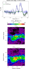 |
Fig. 1 Top: brightness temperature profile (black) for the line of sight indicated by the white cross in the middle and bottom panels, the running mean (green), and the corrected brightness temperature (blue) computed as the difference between the original profile and the running mean. Middle: original integrated brightness temperature of 13CO(2−1) from APEX, denoted as |


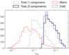 |
Fig. 2 Dust optical depth distributions. The grey line corresponds to the result obtained by fitting a single dust component model and the others to the fit result for the two dust components model. |
3 Methods
Our goal is to create a map of the total hydrogen column density in the CMZ by combining H I data and CO isotopologue observations. In this section, we explain the process of decomposing the velocity profiles of H I and CO data into individual emission lines, which allows us to distinguish the CMZ from the gas in the disk. By using simulation predictions and empirical corrections, XCO factors are derived for each emission line.
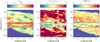 |
Fig. 3 From left to right: longitude-velocity diagrams of the number of 12CO lines, the brightness temperature ratio of 12CO to 13CO, and the 12CO line width. For each (l,v) pixel, the number of lines is summed over latitudes while the two other quantities are averaged. The maps have been smoothed with a Gaussian kernel of 2 pixels in standard deviation for display. The contours give the outline of the two components separated by hierarchical clustering using these three parameters maps as input. Pixels outside of the contour are associated with the CMZ, and those inside are associated with the disk, if they also verify the other conditions described in the text (see Sect. 3.2). |
3.1 Line profile decomposition
For each longitude and latitude, the brightness temperature profile as a function of velocity is decomposed in multiple line contributions following the method of Planck Collaboration Int. XXVIII & Fermi Collaboration (2015); Remy et al. (2017). Detecting lines consists of finding the velocities at which there are local minima in the second derivative of the brightness temperature profile. At these velocities, the brightness temperature presents a local maximum or a change of slope, indicating the presence of a line.
A Gaussian smoothing is applied to the profile before line detection to reduce fluctuations due to noise. Then, the second derivative of the smoothed profile is computed. Only lines found as a local minima of the second derivative within a range Δv (minimal line separation) and above σThr times the threshold TThr are considered. TThr is defined as the standard deviation of the profile computed after clipping TB values below the median of the full profile plus the median absolute deviation. The parameters used for the line detection in the emission profiles are listed in Table A.1 in the Appendix.
Each detected line is then modelled as a pseudo-Voigt function: pV = ηL + (1 − η)G where 0 < η < 1 is the form factor, G a Gaussian and L a Lorentzian distribution. These two functions are expressed as  and
and  where h is the height of the line, σ its width and v0 its central velocity. v0 is constrained into the range [v⋆ − dv; v⋆ + dv] with dv being the velocity resolution of the survey, and v⋆ the velocity of the line obtained previously in the detection step.
The sum of their contributions is fitted to match the observed brightness temperature profile. So for each detected line, the best-fit parameters for η, h, σ, and v0 are found through a χ2 minimisation method.
In order to preserve the observed photometry, we calculate the residuals between the observed and fitted spectra in each velocity channel, and we redistribute them among the fitted lines proportionally to their intensity in that channel. Finally, we compute the integrated intensity for each line by integrating the pseudo-Voigt function along the entire velocity range.
3.2 Disk component separation
The contamination from the Galactic disk to the CMZ CO emission is not negligible. We rely on the differences in gas properties between the CMZ and the rest of the Galaxy to separate these two components.
Higher turbulence levels and shear in the CMZ yield larger velocity dispersion within a cloud and from cloud-to-cloud compared to the disk. Hence, emission lines in the CMZ are more spread apart in velocity. For any given line of sight, the number of emission lines, Nlin, is higher in the Galactic disk than in the CMZ, while the average line width  is higher in the CMZ. Moreover, a higher turbulence tends to decrease the optical thickness of the 12CO(1−0) emission lines, increasing their maximal brightness temperatures T12CO. As the 13CO emission lines are less optically thick, they are less affected. Therefore, the ratio of the brightness temperatures T12CO/T13CO is higher in the CMZ compared to the Galactic disk.
We first separate the disk gas from the CMZ in the 13CO(1−0) brightness map by considering, Nlin,  and T12CO/T13CO. For each longitude and velocity value we compute the sum of Nlin,12CO, and the average of T12CO/T13CO and
  over the small latitude range of our map. Theses parameters maps as a function of (l, v) are shown in Fig. 3. We then use an inductive clustering approach to isolate two clusters in this parameter space. First, we perform an agglomerative clustering3 using only 20% of the (l, v) pixels, randomly chosen. Then, the obtained clusters are used to train a support vector classifier (SVC)4. This classifier is applied to the full data, giving us a boolean mask in longitude and velocity.
Finally, we add two conditions on individual line parameters for the disk component: (i) upper limits of 100 and 5 K km s−1 on the integrated intensity of 12CO(1−0) and 13CO(2−1), respectively. (ii) upper limit of ±80 km s−1 for the line velocity. These values are chosen because higher values will be reached mostly towards CMZ clouds. The same mask is used for 12CO(1−0), 13CO(2−1), and H I data. The result of the component separation for the final column density maps is presented in Sect. 5.1.
3.3 Hydrogen column density estimates
3.3.1 Atomic phase: NHI
The column density of atomic hydrogen, NHI, is given by:  (4) with XHI = 1.82 × 1018 cm−2(K km s−1)−1 the conversion factor. TB is the brightness temperature obtained after continuum subtraction (McClure-Griffiths et al. 2012) and after applying the H I absorption correction described in Section 2.1.1. Thanks to the components separation (Section 3.2) we can split the lines associated to the disk and the CMZ so
  . Then NHI is computed independently for each component. TS = 146.2 ± 16.1 K is the spin temperature derived by measuring saturated brightness in the radial-velocity degenerate regions towards the GC given by Sofue (2017). This value is valid for the gas in the disk but not necessarily for the gas in CMZ since it is not well-resolved in H I data. We assume the same TS value for the disk and CMZ components. The effect of the spin temperature choice is further discussed in Sect. 5.2.
3.3.2 Molecular phase: NH2
The CO line emission is usually scaled into molecular hydrogen column density as  (5)
(5)
The XCO factor can vary within a cloud and across the Galaxy depending on several environmental parameters. Its variation due to the surface density, the metallicity, the far UV radiation field strength and the CR ionisation rate has been studied by Gong et al. (2020) using 3D magnetohydrodynamic simulations, for a range of observational beam sizes. We use their results to describe the evolution of XCO with metallicity, Z (in units of Z⊙), resolved scale, r, and integrated intensity of each line decomposed in velocity, W :  (6)
(6)  (7) where f and g are derived from the mean values given by the simulation (see yellow points in Figure 10 and 15 of Gong et al. (2020) for 12CO(1−0) and 12CO(2−1), respectively). As these reference values were computed for Z = 1 and r = 2 pc we correct them for the resolved scale, so
  , and a similar correction applies to g.
Another key parameter at play in the CMZ is the increased level of turbulence, which yields a larger velocity dispersion, effectively reducing the optical thickness of the CO lines compared to the gas in the disk. The simulation of Bertram et al. (2016) considers different turbulence levels by varying the virial parameter, defined as the ratio of kinetic and potential energies. We notice that variations of this parameter mostly modify the shape of the XCO as a function of WCO at high WCO values (after the minimum in XCO), while at low WCO the average trend is unchanged (and very similar to the one predicted by Gong et al. 2020). So we propose that the effect of the turbulence can be taken into account empirically by adding a power-law correction to Eq. (6) such as  (8)
(8)
The comparison of the XCO predictions from these two simulations is shown in Fig. 4 and the result of this correction on the XCO evolution with WCO is further discussed in Sect. 4.2.
We note that these simulations provide only the trend for  while we have
  observations. So we derive a median conversion factor
  between 12CO(1−0) and 13CO(1−0) isotopes, for which we have both observations available (and they correlate well enough to use only the median as scaling factor, see top panel of Fig. 5). This assumes that the
  value is similar for the two transitions. The observations by Nishimura et al. (2015) in Orion clouds support this assumption, finding moreover similar value of
  as the one we calculate for the GC.
This translates to:  (9)
(9)  (10)
(10)
In the simulations of Bertram et al. (2016), there is no evidence of saturation in the 13CO(1−0) transition, so the XCO is nearly constant at large WCO, and the turbulence parameter has little impact. So, for rarer isotopes, we do not introduce the η parameter. We check the correlation of 13CO(2−1) with C18O(2−1) (see bottom panel of Fig. 5) and find no evidence of saturation except towards the core of Sgr B2 and the GC. In these regions, we use a similar approach to Yan et al. (2017) (see the text describing Figure 3 in their paper) and derive a saturation- corrected  using as substitute
  scaled by the WCO ratio found in the regime where a linear relation exists between the two isotopes. So for
  :
:  (11) and if
  ,
,  (12)
(12)
Finally, we re-scale the trend predicted by the simulations by fitting the Z and η parameters such that the H2 column density maps derived from 12CO(1−0) lines matches the ones obtained from 13CO(2−1) lines:  (13)
(13)  (14) where XCO,i and WCO,i are the quantities derived for each line decomposed in velocity. The difference between the two NH2 estimates is minimised using a least squared method. The CMZ and disk parameters can be fitted independently thanks to the component separation. The best-fit parameters are given in Sect. 4.2.
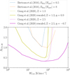 |
Fig. 4 Mean trend for the XCO factor evolution as a function of WCO as predicted by simulations, adapted from Figure 6 of Bertram et al. (2016) and Figure 10 of Gong et al. (2020). The effect of the turbulence is taken into account in Bertram et al. (2016) by varying the ratio of kinetic and potential energies (dotted curves). The dashed curves correspond to the reference functions from Gong et al. (2020), noted |

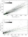 |
Fig. 5 Top: integrated line intensities of 13CO versus 12CO isotopes for the (1–0) transition. Bottom: integrated CO line intensities of the C18O versus 13CO isotopes for the (2–1) transition. Green full lines correspond to linear relation for which the slope is the median WCO ratio; dashed lines give 1σ errors from the 16 and 84 percentiles. |
4 Results and discussions on CO lines properties
As detailed in the previous section, our NH2 estimates require two CO isotope ratios and several environmental parameters in order to derive XCO. These quantities and associated errors are given in the following.
4.1 Isotope integrated intensity ratios
The integrated intensities of the (1–0) transition for the 12CO and 13CO isotopes are well-correlated, with a Pearson correlation coefficient of 94%. This can be seen in the 2D histograms in the top panel of Fig. 5. Over the whole range of WCO, we find a median ratio  (the positive, and negative errors are derived from the 16, and 84 percentiles, respectively). This value is slightly larger but still compatible with the mean value 0.12±0.01 reported in an earlier study using the same data (Tokuyama et al. 2019), even if we do not mask out the disk component, and despite the additional baseline correction we applied (see Sect. 2.1.2).
The integrated intensities of the (2–1) transition for the C18O and 13CO isotopes are shown in the bottom panel of Fig. 5. Over the whole range of WCO, the correlation is only of 77%. Indeed we note departures from linearity: (i) at large WCO, in correspondence with the core of Sgr B2 and Sgr A, where the 13CO intensity saturates; (ii) at low WCO where there is not enough sensitivity, especially to detect the C18O emission, and lower signal-to-noise ratio. In the intermediate range  , where we have a more linear relation, we measure a median ratio
  .
.
The good correlation between 12CO(1−0) and 13CO(1−0) over a large range of WCO values and the absence of saturation, except towards the core of Sgr B2 and Sgr A, hints that the lines’ optical thickness does not rise steeply and remains rather low in most directions towards the CMZ. By adopting the local thermal equilibrium (LTE) approximation, Tokuyama et al. (2019) estimated that the 12CO(1−0) line optical depths distribution towards the CMZ peaks at 3, and values larger than 10 originate predominantly from regions with large contamination from the disk. Earlier studies as Dahmen et al. (1998) have already shown that the optical thickness is much lower in the CMZ (τ ⪅ 2 for W12CO/WC18O >60) than in the disk (τ ≥ 10), except towards few dense cores such as Sgr B2. Sawada et al. (1999) also reported lower 12CO(1−0) optical depths in the GC compared to the disk, which they explained as follows: (i) even for similar densities, higher temperatures excite many molecules to high-J states, reducing optical depths for lower-J transitions. (ii) larger velocity dispersions, caused by strong external pressure and tidal shear in steep gravitational potential, further reduce optical depths.
4.2 XCO fit parameters
The parameters controlling the evolution of XCO that cannot be taken from the literature are estimated from the fit, minimising the difference of the NH2 estimates from the two isotopes using a least-squared method. The systematic uncertainties on the model are estimated as a fractional value of predicted NH2, such that the reduced χ2 reaches unity. This condition is verified considering an error of 10% for the estimate derived from 13CO(2−1), and 33% for the one derived from 12CO(1−0), the latter is larger due to the line saturation.
Thanks to the component separation, parameters for both the CMZ and the disk can be fitted. The resolved scale for the CMZ component is rCMZ = 2.8 pc, given the angular resolution of 0.02° and a distance to GC of 8.18 kpc (GRAVITY Collaboration 2019). The metallicity in the central parsec of the Milky Way was measured by Do et al. (2015) from K-band spectroscopy of 83 late-type giants stars, and they found a mean value of [M/H] = +0.4 ± 0.4 dex. Other studies support that the GC contains mainly a metal-rich population of stars with a mean metallicity of +0.2 dex Schultheis et al. (2019) or +0.3 dex Nandakumar et al. (2018). It should be noted that the stellar metallicity does not always match the gas-phase metallicity, at the centres of massive Galaxies (>1010 M⊙) the stellar metallicity tends to be slightly higher in average (Fraser-McKelvie et al. 2022; Zinchenko & Vílchez 2024), but the differences remain lower than the uncertainties for the centre of our Galaxy. If the metallicity is fixed to ZCMZ = 2.5 according to the higher mean value reported in the literature, then the index obtained from the fit is ηCMZ = −0.71 ± 0.01. This matches the expectations for the CMZ as η values lower than zero correspond to an increased level of turbulence compared to the reference value (η = 0). If the metallicity is left free, we find ZCMZ = 1.92 ± 0.02 (∼ + 0.3 dex) and ηCMZ = −1±0.1, which is still compatible with the measured metallicities and the η < 0 expectation for the CMZ. However, in that case, there is some degeneracy between the two parameters, and the quality of the fit is worse at large NH2, so in the following, we consider the results from the fit at fixed metallicity shown in Fig. 4.
For the disk component, we only considered mean parameters for simplicity, but this approximation still offers a first-order correction compared to studies that do not consider its different properties. The impact of this approximation is limited because most of the disk gas towards the CMZ belongs to the inner regions that have much larger densities than the outer regions, so the average values are driven by the gas in a limited range of distances with rather similar properties. Moreover, given the moderate contribution of the molecular gas in the disk towards the CMZ, this approximation will not introduce a severe bias on the total column density derived. Nevertheless the fitted parameters for the disk component should be considered as nuisance parameters, they are given only for completeness, and not for physical interpretations. The parameters fitted are a mean index  , and a mean distance,
  . This distance yields a mean resolved scale of rdisk = 0.8 ± 0.1 pc. A mean metallicity
  is derived from the fitted distance considering a gradient of −0.047 dex/kpc as measured by Lemasle et al. (2018) using Gaia DR2 data. Even if we do not want to interpret these values, we can still note that the fitted trend goes in the right direction with lower metallicity and larger η (so lower turbulence) in the disk component compared to the CMZ.
The statistical uncertainties on the parameters controlling XCO, derived for the CMZ regions as a whole, are only a few percent. By contrast, the systematic uncertainty on the NH2 estimates is much higher with values of 10–30%. This could be explained by variations of the isotopes ratio, as indeed their dispersion is of similar order (simulations show large uncertainties as well). Moreover, variations of the metallicity across the CMZ could contribute to the variations of the XCO factor. Furthermore, it is unclear how the turbulence parameter would vary depending on the position of the cloud and its dynamic with respect to the GC.
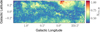 |
Fig. 6 Map of XCO,20, the CO-to-H2 conversion factor in units of 1020 cm−2 K−1 km−1 s, averaged for each pixels. |
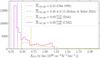 |
Fig. 7 Histogram of the XCO factor derived for each fitted line. The grey dashed, and dashed-dotted lines correspond to the average measurements of Oka et al. (1998), and Kohno & Sofue (2024), respectively. The magenta, and yellow lines corresponds to the median of XCO maps for the CMZ, and disk components. Negative and positive errors are derived from the 16 and 84 percentiles of the maps. |
4.3 Xco variations
XCO is derived for each detected line considering Eq. (8) with the fitted parameters given in Sect. 4.2. The map in Fig. 6 gives the average XCO in each direction. Each pixel value in the XCO map is the WCO-weighted average of the XCO over all the detected lines belonging to a given component in that direction. The overall distributions of XCO per detected line for each component are shown in Fig. 7.
For the CMZ component, the XCO values are in the range (0.32–1.37) × 1020 cm−2 K−1 km−1 s for each line, but the distribution is very asymmetric and very skewed towards the lower bound. This directly comes from the fact that most detected lines have WCO between few tens and few hundreds of K km s−1, and the XCO(WCO) profile is nearly flat close to its minimum in this regime. After integrating XCO in each direction and averaging over the map, we obtain a median value for the CMZ component of  . This median value is compatible with most of the results found in the literature that usually report average values for the CMZ in the range (0.2–0.7) × 1020 cm−2 K−1 km−1 s (see Table 3 of Kohno & Sofue 2024, and references therein).
For the disk component, the distribution is also asymmetric with more low values but less peaked. The spread is larger with values in the range (0.49–2.87) × 1020 cm−2 K−1 km−1 s, and the median is 0.69 × 1020 cm−2 K−1 km−1 s. We note that this median value for the disk is not comparable to the usual Galactic average value, first because it is only derived for a small region towards the GC, and secondly because of the approximations made in the XCO evolution model of this component discussed in the previous section.
A recent study from Kohno & Sofue (2024) derived XCO maps in the CMZ from CO isotopologues using a very different method. They derived the NH2 from 12CO(1−0) lines using a constant XCO obtained for a given XCO (R) gradient as a function of the Galactocentric radius and the NH2 from 13CO(1−0) line using LTE approximation. Then they fitted an empirical curve to model the relation between the two estimates and used this to derive the XCO values. The drawbacks of this approach are: (i) it depends strongly on the choice of the reference XCO and metallicity gradient, (ii) the validity of the LTE approximation is not guaranteed in every direction for the extreme environment of the CMZ (for details on the limitations of the LTE column density measurement of 13CO see Szűcs et al. 2016). So the XCO variations they report might also reflect the limit of these hypotheses. The XCO map they obtained is shown in Figure 3 of their paper. The comparison with our results is limited by the differences in resolution (ours is 10 times coarser), coverage (they show results only where WCO > 500 K km s−1), and CMZ component separation method. However, the range of XCO values obtained is comparable, and the average estimates for the whole region are compatible. This agreement can be explained because the average value of XCO is mainly driven by the metallicity gradient assumed. Indeed they rely on the results from Arimoto et al. (1996) that yield a XCO ∝ Z−1, which is not far from the trend of Z−0.8 we use as given by the simulation of Gong et al. (2020).
We note that observations of CII and dust in external Galaxies suggest a trend in Z−α with α ∼ 1–2, that is, larger than the prescription from simulations we used, but the sample studied include mostly low-metallicity systems where steeper variations are expected (see Figures 1b and 2a of Teng et al. 2024; Schinnerer & Leroy 2024, respectively, and references therein). Moreover comparison of the dependence in metallicity only is not necessarily straightforward as many other parameters play a role.
5 Hydrogen column density and masses per phase and per component
5.1 NH maps products
The quantity of gas in the molecular phase is taken as the average of the two NH2 estimates obtained from Eqs. (13) and (14), which use the XCO factors derived for each fitted line. The relative uncertainty between the two estimates as a function of the mean is shown in Fig. 8. On average, the (2–1) estimate is 5% higher, and with a 30% dispersion. However, the uncertainty increases at lower NH2 and becomes more asymmetric. Indeed, at low NH, the shape of the XCO (WCO) curves from the simulation is not corrected by the fit, and it cannot fully capture the variations of the XCO of the two tracers close to their sensitivity thresholds where the relative uncertainty on WCO is also large. In that regime, the use of higher sensitivity surveys and other tracers that can probe lower column densities could be considered to refit the XCO curves. However, such studies would be more suited towards isolated local clouds, for which we can better resolve the envelop of the clouds. In the GC, this uncertainty on the evolution of XCO at low NH2 is not the main source of uncertainties as the absolute uncertainty is still dominated by higher column densities at NH2 > 4.9 × 1022 cm−2, and the molecular gas is not predominant at low column densities.
The hydrogen column density maps in atomic and molecular phases, as well as total maps for all the gas, the disk component and the CMZ component are shown in Fig. 9. The relative uncertainty with respect to the average NH2 estimate is shown in A.3 in the appendix. Maps of the fraction of molecular hydrogen, fH2, and of the fraction of the disk contamination, fdisk, in the total column density are displayed in Fig. 10. The contribution of the atomic gas towards the GC is still ∼15–30%; if we remove the disk contamination, this value is reduced to ∼5–15% for the CMZ clouds. The atomic gas fraction increases to 50–70% in the regions that are dominated by the disk component at only 0.2° from the CMZ clouds. This is particularly important for γ-ray analyses as the diffuse Galactic emission comes mostly from the γ rays produced by the interaction of CR with all the interstellar gas. Then, the contribution of the atomic phase and the disk gas contamination should not be neglected, even towards the CMZ clouds.
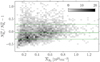 |
Fig. 8 Relative uncertainty on the hydrogen column density in the molecular phase estimated from two different CO transitions as a function of the average estimate. The solid green line corresponds to the median ratio, dashed lines gives 1σ uncertainty from the 16 and 84 percentiles. |
5.2 Mass estimates
The gas mass, M, is given as a function of the total hydrogen column density, NH = NHI + NH2, by:  (15) with d the distance to the observer, dΩ the solid angle, mH the atomic mass, and μ = 1.4 the mean molecular weight (same as in Sofue 2022b).
The resulting gas masses in the atomic and molecular phases and the total value towards the GC within −0.8° < l < 1.4° and |b| < 0.3° are presented in Table 2. The table also provides the mass for CMZ and disk components separately. We note that the value for the disk is only computed considering the distance of the CMZ in order to evaluate the bias on the total mass estimate that would be introduced by the absence of component separation (as typically given by dust-based estimates). The total gas mass in the CMZ is found to be  with only ∼10% contribution from the atomic gas. If we also consider the gas in the disk component, we reach
  and the atomic gas contribution rises to ∼30%.
The masses derived in the molecular phase are very similar to those of Sofue (2022b) that found values 2.8 × 10⁷ M⊙ in total and 2.3 × 10⁷ M⊙ in the CMZ after removing the disk contamination (with another method). The small differences could be due to their slightly different region definition (−1.1° < l < 1.8° and |b| < 0.2°) and the use of a constant XCO factor. In the atomic phase, we found a total mass 3 times higher than the values they reported. This discrepancy can be simply explained by two factors: (i) they derived a minimal mass for the optically thin case while we use a spin temperature of TS = 146.2 ± 16.1 K (Sofue 2017) which yield to 1.6 times higher mass; (ii) the method we use to correct for self-absorption allows to recover about 1.7 times more mass. Even with this higher H I mass, the molecular gas fraction we find in the CMZ clouds after removing the disk contamination is still as high as ∼85–95% and decreases only by a few per cent compared to the values of ∼90–98% reported by Sofue (2022a).
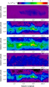 |
Fig. 9 Hydrogen column density for the different phases H I, H2, Htot = H I + H2, and the two components, disk and CMZ, separated. |
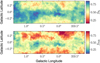 |
Fig. 10 Top: fraction of H2 in the total hydrogen column density. Bottom: Fraction of disk component in the total hydrogen column density. |
Gas mass per phase and per component in solar masses towards the GC within −0.8° < l < 1.4° and |b| < 0.3°.
6 Dust opacity variations
The optical depth, τν, can be related to the dust mass, Mdust, and gas column density, NH, as follows:  (16)
(16)  (17) where κν is the dust emissivity cross section per unit mass, σν = κνrdgμmH is the dust opacity, rdg is the dust-to-gas mass ratio, and μ is the mean molecular weight.
The opacities derived at 353 GHz from the optical depth obtained with the single, and two-component dust models are shown in the top, and bottom panel of Fig. 11, respectively. The values derived for the two-component model are systematically higher by a factor 2 to 12. We also note differences comparing our two-components model to one of Meisner & Finkbeiner (2015), which has less free parameters (we fit βcold, βwarm and Tcold in each line of sight). The values of the optical depth at 545 GHz, τ545, we obtain at the same resolution are within a factor 0.85–2.3 compared to the τ545 values derived by Meisner & Finkbeiner (2015). This illustrates that the hypotheses used for the dust emission fit have a strong impact on the results obtained.
In the following we discuss the dust optical depth and opacity values derived from the single-component dust model as there are more references for comparisons in the literature. The average opacity in the H I dominated regions is 1.36 ± 0.28 10−26 cm2. Similarly regions dominated by the disk component (which mostly correspond to regions dominated by atomic gas) have an average opacity of 1.39 ± 0.43 10−26 cm2. These values are quite close to what is found in the H I phase of local clouds (see Tables 2 of Planck Collaboration Int. XXVIII & Fermi Collaboration (2015) and Remy et al. (2017)) and twice larger than the values found in the most diffuse regions at high latitudes (see Table 4 of Planck Collaboration XI 2014). Large variations up to a factor of 9 above these averages are found towards dense molecular clouds such as Sgr B2 and Sgr C. This trend is again similar to what is found in local clouds but in the GC more extreme values are reached.
In Fig. 12, we attempt to model the variation of τ353 as a function of NH with a non-linear relation as done in earlier studies (Roy et al. 2013; Okamoto et al. 2017; Hayashi et al. 2019). However we can see that there is a large dispersion around the fitted trend, and the fit residuals are very structured. This suggests that assuming only the non-linearity of NH is not sufficient to model the dust opacity variations and that other mechanisms are at play.
The variations of the opacity with dust spectral index, temperature, and cold-to-warm optical depth ratio are shown in Fig. 13. In the left panel we show that the opacity raises with increasing β and decreasing Tdust as observed in local clouds (see Figure 18 of Remy et al. 2017). Theoretical works suggest that grains evolution in denser media involving consecutively the accretion of carbonaceous mantles, grain coagulation, and ice mantle formation progressively alter the emissivity of the grains. These processes can explain the increase in opacity with gas density (up to a factor 7) and the associated changes in spectral index β, and colour temperature as shown by Köhler et al. (2015).
Despite the agreement with the trend of variations seen in local clouds, the ranges of opacity, spectral index and colour temperature values measured in the CMZ are broader. In Fig. 14, we can see that the opacity increases as the cold-to-warm dust ratio in optical depth decreases. The enhanced contamination from warm dust, interestingly correlates not only with an increase in opacity but also with an increase in β, and a decrease in colour temperature (see middle and right panels of Fig. 13, respectively). It is unclear whether this effect is due to a degeneracy of the parameters fitted to the spectral energy distribution, or to a physical process. As pointed by Ysard et al. (2019) the spectral index measured on dust analogues in laboratory are not always straightforward to compare with the ones derived from astronomical observations. Indeed the observed spectral index can be significantly altered by the dust temperature distribution along the line of sight, which is influenced by heating sources and the structure of the ISM.
Other possible causes of increase in opacity are the raise of the dust-to-gas mass ratio with enhanced metallicity, and turbulence. The correlation between dust-to-gas mass ratio and metallicity reflects the progressive chemical enrichment of the ISM with dust created from heavy elements ejected by stars at the end of their lifetime and by stellar winds. However the correlation is more marked at low metallicity, while at solar metallicity and above the dust-to-gas mass ratio seems to flatten (see Figures 1, 3, and 8 of Galametz et al. 2011; Li et al. 2019; Galliano et al. 2021, respectively, and references therein). The enhanced turbulence level in the CMZ could also increase the dust-to-gas mass ratio, indeed Tricco et al. (2017) found evidence of grain-size dependent sorting of the dust, because turbulence preferentially concentrates larger grains into dense regions.
Given the complex dependency of the changes in dust opacity with the unknown dust composition and the environment all along the line of sight towards the GC, it is very complicated to rely on a physical model of dust evolution. Moreover the empirical models describing the dust opacity are hardly transposable from one region to another. In particular gas mass estimated from the dust emission using a simple averaged opacity as scaling factor would be highly unreliable. For example considering the average opacity of 8.4 × 10⁻²⁷ cm2 measured by Planck Collaboration XI (2014) over the whole sky would yield to a CMZ mass of 1 × 10⁸ M⊙, more than a factor 2 higher compared to the total mass estimation discussed in Sect. 5.2 (and also higher than historical measurements reported in Table 2 of Dahmen et al. 1998). If we take into account the dust evolution in different media with a minimal model considering an average opacity of 14 × 10−27 cm2 in the H I dominated regions and an opacity enhanced by a factor 1.5–3 on average for H2 dominated regions (similar to what is found in local clouds), it yields masses of 2.2–4.1 × 10⁷ M⊙ comparable to the total gas estimates from H I + CO lines. Towards the CMZ, and the Galactic plane in general, dust is not necessarily a more reliable tracer of the total gas because the opacity evolution with environment is as complex, if not more, than the evolution of the XCO factor.
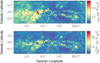 |
Fig. 11 Top: dust opacity at 353 GHz, σ353 = τ353/NH, derived from the single component fit. Bottom: total dust opacity at 353 GHz, derived from the two-components fit. In both cases, NH is the total hydrogen column density shown in the third panel of Fig. 9. |
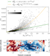 |
Fig. 12 Top: dust optical depth as a function of NH. The green line corresponds to a linear relation for which the slope is the mean opacity in the regions dominated by atomic gas (fH2 < 0.5). The orange curve corresponds to the best-fit τ353 as a function of NH with a log-parabola model. Bottom: relative error on the fit. |
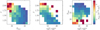 |
Fig. 13 Evolution of the dust opacity with dust spectral index β, dust temperature Tdust (single-component), and the cold to warm component ratio in dust optical depth, |

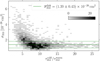 |
Fig. 14 Dust opacity as a function of the cold to warm component ratio in dust optical depth, |

7 Impact on cosmic-ray density estimation
The diffuse γ-ray Galactic emission comes mostly from the γ rays produced by the CR interaction with the interstellar gas (as a product of the decay of neutral pions created in protonproton interactions). Assuming that other contributions to the diffuse γ-ray emission are negligible, the CR energy density can be expressed as a function of the γ-ray luminosity Lγ above a given energy Eγ, and the gas mass M by:  (18) where ηN = 1.5 accounts for the presence of nuclei heavier than hydrogen in both CR and interstellar matter.
H.E.S.S. Collaboration (2016) used this relation5 to derive the CR density above 10 TeV (Eγ ≥ 1 TeV) in several regions towards the CMZ (see Figure 1 and 2 of their paper). In their work the mass in each region is simply taken as a fraction of the total mass, assumed to be 3 × 10⁷ M⊙, weighted by the integrated intensity in the region compared to the whole map. Three different estimates are given based on different tracers: CS, CO and HCN lines. This approach implicitly assumes a constant conversion factor, ignores the gas below the critical density of the tracers considered, and ignores the contribution of the atomic gas which increases with increasing absolute latitudes. As mentioned previously, CRs interact with the interstellar gas in all its phases, so the contribution from both the diffuse atomic hydrogen and the lower-density molecular gas in the disk should not be neglected, even towards the CMZ clouds.
We recompute the CR energy densities in the regions they analysed considering our total gas mass estimate. The results are summarised in Fig. 15; the top panel shows the gas mass comparison, the middle panel shows the fraction of disk contamination in the total hydrogen column density, and the bottom panel shows the CR energy density. The largest deviation in mass and CR density is found in the three first regions that include more disk contribution because they extend at higher latitudes.
H.E.S.S. Collaboration (2016) fitted the wCR values with a 1/r profile in CR density integrated over the line of sight which suggests a continuous injection from a central accelerator (potentially Sgr A*, the central super massive black hole). However, the CR density derived from the total γ-ray luminosity and total gas mass is a weighted average over the line of sight, so their analyses implicitly assume that most of the γ rays originate from the CMZ and that contribution from the disk is negligible. This assumption may not hold because: (i) We shown here that the gas mass in the disk contributes to 25–60% in the regions considered; (ii) Several studies reported an enhancement of the CR density (or γ-ray emissivity per gas nucleon) in the disk up to a factor of three compared to the local value (see Figure 3 at the end of Tibaldo et al. (2021) for a compilation of Fermi-LAT at GeV energies, and Figure 2 of Cao et al. (2023) for LHAASO measurement at TeV energies). H.E.S.S. Collaboration (2016) calculated a local value of wCR,local(≥ 10 TeV) ∼ 10−3 eV cm−3, so an enhancement factor of three in the disk would already account for half of the CR density found in two of the regions considered, therefore it is unlikely to be negligible.
In order to take into consideration the contamination from the disk, we fitted the wCR values with two components via a χ2 minimisation:  (19)
(19)
The fractions fCMZ and fDisk are the weight of the CMZ and disk components in the total gas column density, respectively. The CR energy density in the CMZ is modelled with the same 1/r profile integrated over the line of sight as in H.E.S.S. Collaboration (2016), noted w1/r, for which we refit only a normalisation, and find  . The other fitted parameter is
  that gives the average level of the CR sea in the disk towards the GC. Even if the uncertainties are large, the two-component model clearly improves the fit by 4.9 σ over a single uniform value and by 2.6 σ over a 1/r profile only. Considering two components yields to about two times larger wCR in the CMZ compared to the previous study, since our result is not biased downward by the mixture with disk contribution that has lower wCR values. Interestingly the average value found in the disk is a factor of four times the local value, which is consistent with the enhancement reported in the studies cited in the previous paragraph. However, the uncertainty is large, so considering more regions and larger regions would be required to further discuss the CR densities across the Galactic disk. Note also that as in H.E.S.S. Collaboration (2016), this fit does not take into account the 3D distribution of the gas across the CMZ, which limits the discussion on the validity of the 1/r distribution for the CR densities. We defer more refined studies considering the distance of the different clouds in the CMZ to future works.
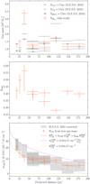 |
Fig. 15 Top: gas mass estimates from H.E.S.S. Collaboration (2016) in grey and from this work in orange. Middle: fraction of disk contamination in the total hydrogen column density. Bottom: average CR density as a function of its projected distance from Sgr A*. The grey items are adapted from H.E.S.S. Collaboration (2016), including the systematic uncertainties associated to the choice of gas tracer, and the correction we discuss in the footnote 5. The grey line is the 1/r profile in CR density integrated over the line of sight provided in their paper as a fit to the data points. The orange error bars give the values derived from our mass estimates. The orange line corresponds to the fit to these points considering a 1/r profile for the CMZ component (magenta) and a constant for the disk component (yellow). |
8 Summary and perspectives
In this study, we analysed the GC region defined by longitudes −0.8° < l < 1.4° and latitudes <0.3°, at an angular resolution of ∼0.02°. We have calculated the total hydrogen column density, taking into account both the atomic and molecular components of the gas, and the contribution from both the CMZ and the foreground and background gas in the disk.
The atomic phase was probed using the H I Galactic Center survey data from ATCA and the Parkes Radio Telescope (McClure-Griffiths et al. 2012). A H I self-absorption correction was applied, to recover more atomic gas in the central ∼1° radius around the GC. Then, the atomic hydrogen column density has been computed with a spin temperature TS ⋍ 150 K (Sofue 2017).
For the molecular phase, CO isotopologue line emissions has been used: 12CO and 13CO for the J = 1 → 0 transition from the NRO (Tokuyama et al. 2019), and 13CO and C18O for the J = 2 → 1 transition from the APEX telescope (Schuller et al. 2021). A baseline correction was applied to the molecular line data cubes to improve sensitivity and reduce discrepancies across the map. Isotope ratio in integrated intensities have been found to be:  for the median ratio of
  over
over  and
and  for the median ratio of
  over
over  , which is compatible with the value published by Tokuyama et al. (2019).
For each tracer considered and for each (l,b) directions the brightness temperature profiles as a function of velocity were decomposed in multiple line contributions. This profile decomposition helps to identify changes in gas properties. Indeed in the CMZ, higher turbulence and shear lead to greater velocity dispersion within and between clouds, causing emission lines to be more spread apart in velocity compared to the Galactic disk. This increased turbulence also decreases the optical thickness of the 12CO emission lines, raising their maximal brightness temperatures, resulting in a higher ratio of brightness temperatures T12CO/T13CO in the CMZ than in the Galactic disk. These differences in properties were used to perform a component separation between the gas emission from the CMZ and from the Galactic disk. The profile decomposition and the component separation allowed us to derive a XCO value for each line considering different XCO evolution models for the CMZ and the disk gas.
The evolution of the XCO factor as a function of CO integrated intensity, metallicity, and resolved scaled, was modelled using theoretical trends from simulations in Gong et al. (2020). An empirical power-law correction was added to take into account the effect of the increased level of turbulence in the CMZ following Bertram et al. (2016). The index of the power-law correction η for each component were derived using a fit by minimising the difference between the gas estimates found adopting different isotopes. In the main analysis the average metallicity in the CMZ is fixed to a value from the literature, but if left as a free parameter we found a value ∼ + 0.3 dex which is compatible with the super-solar metallicities reported in several studies (Do et al. 2015; Nandakumar et al. 2018; Schultheis et al. 2019). For the CMZ component, the XCO values per line range from (0.32–1.37) × 1020 cm−2 K−1 km−1 s, with a distribution that is highly asymmetric and skewed towards the minimum value. This is because most detected lines have WCO values between a few tens and a few hundreds of K km s−1, where the XCO (WCO) profile is nearly flat. After integrating XCO in each direction and averaging over the map, the median value for the CMZ component is found to be  .
.
Separate maps for the atomic, molecular and total gas were computed for the CMZ and the Galactic disk components. The total gas mass estimated in the CMZ is  with only 10% contribution from the atomic g-as (similar to the estimates from Sofue 2022b). Without removing the disk contamination the total mass is about twice higher, and the atomic gas fraction increases to ∼30%. Therefore the contamination from the gas in the disk is not negligible, and the same holds for the H I contribution to the total gas mass in the GC region as well.
Modelling the dust opacity changes towards the GC (and the Galactic plane in general) is very complex due to the unknown dust composition and varying environments along the line of sight. The gas mass estimates from dust emission are far to be free from uncertainties, and we stress that the use of a simple average opacity as scaling factor would be very unreliable, and would lead to mass overestimation.
Estimating the total gas content in the GC region is particularly important for γ-ray astronomy, as it plays a key role in determining the CR density from the observed γ-ray emission and the total mass of interstellar gas. We recalculated the CR energy density wCR using the formalism adopted in H.E.S.S. Collaboration (2016), and our new estimates of the total gas mass. Firstly, we found consistent gas mass for the different regions selected, except for their first three regions, where the disk contribution is higher due to their extent up to high latitudes. Secondly, we fitted the CR energy density accounting for two components, the CMZ and the Galactic disk, in order to take into account the contamination from foreground and background gas that was previously neglected. The CMZ component was modelled with the same 1/r profile, while the added disk component represents the average level of the CR in the disk towards the GC. We found that the two-component model is preferred by 4.9σ over a uniform value, and by 2.6σ over the 1/r profile. As a result, the CR energy density in the CMZ is higher by a factor of two compared to previous measurements, and the average value for the disk towards the GC is found to be four times higher than the local value.
To further refine our model, it is necessary to consider the three-dimensional distribution of CRs and gas in the GC. However, this aspect will be addressed in a subsequent study. Understanding the 3D gas distribution in the CMZ is crucial for comprehending the formation and evolution of this structure, as well as for addressing broader questions related to star formation sites and CR transport (Mills 2017; Dörner et al. 2024). There are already some indications about the structure of the CMZ. For instance, Ferrière et al. (2007) suggested that it has an asymmetric ring-like shape. Additionally, Scherer et al. (2022) deduced from γ-ray maps that an inner cavity must be present. The giant molecular clouds in the CMZ are thought to follow a ‘twisted-ring’ orbit, as proposed by Molinari et al. (2011). Nevertheless, the exact spatial configuration of these clouds on the orbit remains a topic of debate (Henshaw et al. 2023). To achieve a more precise 3D mapping, the region should first be divided into individual clouds using clustering algorithms similar to those described by Miville-Deschênes et al. (2017). The position of these clouds can then be determined using one of two methods: directly estimating the line of sight distance through absorption lines (Yan et al. 2017; Sofue 2022b), or calculating the distance to the supermassive black hole (SMBH) by analysing the clouds’ response to the SMBH’s activity (Marin et al. 2014; Terrier et al. 2018). This problematic of the 3D distribution of CRs and gas in the GC will be explored in future studies.
Acknowledgements
The authors thank S. C. O. Glover and J. A. Hinton for providing their valuable comments and suggestions on the draft, and R. J. Tuffs for the interesting discussions. S.R. acknowledges support from the LabEx UnivEarthS, ANR-10-LABX-0023 and ANR-18-IDEX-0001. S.R. and M.B. acknowledge funding from SALTO exchange program between the CNRS and the MPG. H.R. expresses her gratitude to the support from the International Max Planck Research School for Astronomy and Cosmic Physics at the University of Heidelberg (IMPRS-HD). J.D. acknowledges funding from the Research Council of Norway, project number 301718. We thank the communities behind the multiple open-source software packages on which we depend, in particular astropy (Astropy Collaboration 2022) for FITS files and units handling, gammapy (Donath et al. 2023) for skymaps utilities, matplotlib (Hunter 2007) for visualisation, and numpy (Harris et al. 2020), scikit-image (van der Walt et al. 2014), scikit-learn (Pedregosa et al. 2011), scipy (Virtanen et al. 2020), lmfit (Newville et al. 2023) for all the computation methods they offer.
Appendix A Additional figures and tables
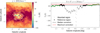 |
Fig. A.1 Left: H I temperature brightness at v = 20 km s−1. Grey contours delimit the regions we consider affected by absorption (because of low temperature brightness and large gradient values). Black contours correspond to a 10 pixels margin around the grey contours that we use as reference region to compute the median or maximum values in the vicinity. Right: H I temperature brightness at v = 20 km s−1 and b = 0°. The median and maximum values are computed along each longitude value considering only the reference pixels (black) and used as substitute for the absorbed pixels (grey). The same operation is applied for each velocity independently. More details are given is the text of Sect. 2.1.1, and the resulting NH maps are shown in Fig. A.2. |
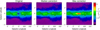 |
Fig. A.2 From left to right: H I column density maps without correction for absorption, with median correction, and maximal correction following the method described in Sect. 2.1.1 and illustrated in Fig. A.1. |
List of parameters used for baseline correction and line detection. In parentheses, we provide the corresponding number of velocity bins, δv.
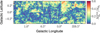 |
Fig. A.3 Relative error with respect to the average NH2 estimate (here the error is taken as the maximal deviation among the two CO isotopes considered). |
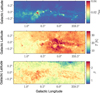 |
Fig. A.4 Parameter maps obtained by fitting the dust emission adopting a single-component model. |
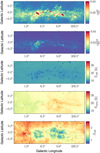 |
Fig. A.5 Parameter maps obtained by fitting the dust emission adopting a two-component model. |
References
- Arimoto, N., Sofue, Y., & Tsujimoto, T. 1996, PASJ, 48, 275 [Google Scholar]
- Astropy Collaboration 2022, ApJ, 935, 167 [NASA ADS] [CrossRef] [Google Scholar]
- Bally, J., Stark, A. A., Wilson, R. W., & Henkel, C. 1987, ApJS, 65, 13 [Google Scholar]
- Bell, T. A., Roueff, E., Viti, S., & Williams, D. A. 2006, MNRAS, 371, 1865 [NASA ADS] [CrossRef] [Google Scholar]
- Bertram, E., Glover, S. C. O., Clark, P. C., Ragan, S. E., & Klessen, R. S. 2016, MNRAS, 455, 3763 [Google Scholar]
- Cao, Z., Aharonian, F., An, Q., et al. 2023, Phys. Rev. Lett., 131, 151001 [NASA ADS] [CrossRef] [Google Scholar]
- Csengeri, T., Weiss, A., Wyrowski, F., et al. 2016, A&A, 585, A104 [NASA ADS] [CrossRef] [EDP Sciences] [Google Scholar]
- Dahmen, G., Huttemeister, S., Wilson, T. L., & Mauersberger, R. 1998, A&A, 331, 959 [Google Scholar]
- Do, T., Kerzendorf, W., Winsor, N., et al. 2015, ApJ, 809, 143 [Google Scholar]
- Donath, A., Terrier, R., Remy, Q., et al. 2023, A&A, 678, A157 [NASA ADS] [CrossRef] [EDP Sciences] [Google Scholar]
- Dörner, J., Tjus, J. B., Blomenkamp, P. S., et al. 2024, ApJ, 965, 180 [CrossRef] [Google Scholar]
- Ferrière, K., Gillard, W., & Jean, P. 2007, A&A, 467, 611 [NASA ADS] [CrossRef] [EDP Sciences] [Google Scholar]
- Finkbeiner, D. P., Davis, M., & Schlegel, D. J. 1999, ApJ, 524, 867 [NASA ADS] [CrossRef] [Google Scholar]
- Fraser-McKelvie, A., Cortese, L., Groves, B., et al. 2022, MNRAS, 510, 320 [Google Scholar]
- Galametz, M., Madden, S. C., Galliano, F., et al. 2011, A&A, 532, A56 [NASA ADS] [CrossRef] [EDP Sciences] [Google Scholar]
- Galliano, F., Nersesian, A., Bianchi, S., et al. 2021, A&A, 649, A18 [EDP Sciences] [Google Scholar]
- Ginsburg, A., Henkel, C., Ao, Y., et al. 2016, A&A, 586, A50 [NASA ADS] [CrossRef] [EDP Sciences] [Google Scholar]
- Glover, S. C. O., & Mac Low, M. M. 2011, MNRAS, 412, 337 [NASA ADS] [CrossRef] [Google Scholar]
- Gong, M., Ostriker, E. C., Kim, C.-G., & Kim, J.-G. 2020, ApJ, 903, 142 [CrossRef] [Google Scholar]
- GRAVITY Collaboration 2019, A&A, 625, L10 [NASA ADS] [CrossRef] [EDP Sciences] [Google Scholar]
- Grenier, I. A., Casandjian, J.-M., & Terrier, R. 2005, Science, 307, 1292 [Google Scholar]
- Guesten, R., Walmsley, C. M., Ungerechts, H., & Churchwell, E. 1985, A&A, 142, 381 [NASA ADS] [Google Scholar]
- Harris, C. R., Millman, K. J., van der Walt, S. J., et al. 2020, Nature, 585, 357 [NASA ADS] [CrossRef] [Google Scholar]
- Hayashi, K., Okamoto, R., Yamamoto, H., et al. 2019, ApJ, 878, 131 [NASA ADS] [CrossRef] [Google Scholar]
- Henshaw, J. D., Barnes, A. T., Battersby, C., et al. 2023, in Astronomical Society of the Pacific Conference Series, 534, Protostars and Planets VII, eds. S. Inutsuka, Y. Aikawa, T. Muto, K. Tomida, & M. Tamura, 83 [NASA ADS] [Google Scholar]
- H.E.S.S. Collaboration 2016, Nature, 531, 476 [CrossRef] [Google Scholar]
- H.E.S.S. Collaboration 2018, A&A, 612, A9 [NASA ADS] [CrossRef] [EDP Sciences] [Google Scholar]
- Hunter, J. D. 2007, Comput. Sci. Eng., 9, 90 [NASA ADS] [CrossRef] [Google Scholar]
- Israel, F. P. 2020, A&A, 635, A131 [NASA ADS] [CrossRef] [EDP Sciences] [Google Scholar]
- Köhler, M., Ysard, N., & Jones, A. P. 2015, A&A, 579, A15 [NASA ADS] [CrossRef] [EDP Sciences] [Google Scholar]
- Kohno, M., & Sofue, Y. 2024, PASJ, 76, 579 [Google Scholar]
- Lemasle, B., Hajdu, G., Kovtyukh, V., et al. 2018, A&A, 618, A160 [NASA ADS] [CrossRef] [EDP Sciences] [Google Scholar]
- Li, Q., Narayanan, D., & Davé, R. 2019, MNRAS, 490, 1425 [CrossRef] [Google Scholar]
- Liseau, R., Larsson, B., Lunttila, T., et al. 2015, A&A, 578, A131 [NASA ADS] [CrossRef] [EDP Sciences] [Google Scholar]
- Liszt, H., & Gerin, M. 2023, A&A, 675, A145 [NASA ADS] [CrossRef] [EDP Sciences] [Google Scholar]
- MAGIC Collaboration (Acciari, V. A., et al.) 2020, A&A, 642, A190 [NASA ADS] [CrossRef] [EDP Sciences] [Google Scholar]
- Marin, F., Karas, V., Kunneriath, D., & Muleri, F. 2014, MNRAS, 441, 3170 [NASA ADS] [CrossRef] [Google Scholar]
- McClure-Griffiths, N. M., Dickey, J. M., Gaensler, B. M., et al. 2012, ApJS, 199, 12 [Google Scholar]
- Meisner, A. M., & Finkbeiner, D. P. 2015, ApJ, 798, 88 [Google Scholar]
- Mills, E. A. C. 2017, arXiv e-prints [arXiv:1705.05332] [Google Scholar]
- Miville-Deschênes, M.-A., Murray, N., & Lee, E. J. 2017, ApJ, 834, 57 [Google Scholar]
- Molinari, S., Bally, J., Noriega-Crespo, A., et al. 2011, ApJ, 735, L33 [Google Scholar]
- Molinari, S., Schisano, E., Elia, D., et al. 2016, A&A, 591, A149 [NASA ADS] [CrossRef] [EDP Sciences] [Google Scholar]
- Morris, M., & Serabyn, E. 1996, ARA&A, 34, 645 [Google Scholar]
- Nandakumar, G., Ryde, N., Schultheis, M., et al. 2018, MNRAS, 478, 4374 [Google Scholar]
- Newville, M., Otten, R., Nelson, A., et al. 2023, https://doi.org/10.5281/zenodo.8145703 [Google Scholar]
- Nishimura, A., Tokuda, K., Kimura, K., et al. 2015, ApJS, 216, 18 [NASA ADS] [CrossRef] [Google Scholar]
- Oka, T., Hasegawa, T., Hayashi, M., Handa, T., & Sakamoto, S. 1998, ApJ, 493, 730 [NASA ADS] [CrossRef] [Google Scholar]
- Okamoto, R., Yamamoto, H., Tachihara, K., et al. 2017, ApJ, 838, 132 [Google Scholar]
- Pedregosa, F., Varoquaux, G., Gramfort, A., et al. 2011, J. Mach. Learn. Res., 12, 2825 [Google Scholar]
- Planck Collaboration XI. 2014, A&A, 571, A11 [NASA ADS] [CrossRef] [EDP Sciences] [Google Scholar]
- Planck Collaboration III. 2020, A&A, 641, A3 [NASA ADS] [CrossRef] [EDP Sciences] [Google Scholar]
- Planck Collaboration Int. XXVIII. 2015, A&A, 582, A31 [NASA ADS] [CrossRef] [EDP Sciences] [Google Scholar]
- Pohl, M., Macias, O., Coleman, P., & Gordon, C. 2022, ApJ, 929, 136 [CrossRef] [Google Scholar]
- Reach, W. T., Dwek, E., Fixsen, D. J., et al. 1995, ApJ, 451, 188 [NASA ADS] [CrossRef] [Google Scholar]
- Remy, Q., Grenier, I. A., Marshall, D. J., & Casandjian, J. M. 2017, A&A, 601, A78 [NASA ADS] [CrossRef] [EDP Sciences] [Google Scholar]
- Ripple, F., Heyer, M. H., Gutermuth, R., Snell, R. L., & Brunt, C. M. 2013, MNRAS, 431, 1296 [NASA ADS] [CrossRef] [Google Scholar]
- Roy, A., Martin, P. G., Polychroni, D., et al. 2013, ApJ, 763, 55 [Google Scholar]
- Sandstrom, K. M., Leroy, A. K., Walter, F., et al. 2013, ApJ, 777, 5 [Google Scholar]
- Sawada, T., Hasegawa, T., Handa, T., et al. 1999, Adv. Space Res., 23, 985 [Google Scholar]
- Scherer, A., Cuadra, J., & Bauer, F. E. 2022, A&A, 659, A105 [NASA ADS] [CrossRef] [EDP Sciences] [Google Scholar]
- Schinnerer, E., & Leroy, A. K. 2024, ARA&A, 62, 369 [NASA ADS] [CrossRef] [Google Scholar]
- Schuller, F., Urquhart, J. S., Csengeri, T., et al. 2021, MNRAS, 500, 3064 [Google Scholar]
- Schultheis, M., Rich, R. M., Origlia, L., et al. 2019, A&A, 627, A152 [NASA ADS] [CrossRef] [EDP Sciences] [Google Scholar]
- Shull, J. M. 2022, Phys. Today, 75, 12 [Google Scholar]
- Sofue, Y. 2017, MNRAS, 468, 4030 [Google Scholar]
- Sofue, Y. 2022a, MNRAS, 516, 3911 [Google Scholar]
- Sofue, Y. 2022b, MNRAS, 516, 907 [NASA ADS] [CrossRef] [Google Scholar]
- Szűcs, L., Glover, S. C. O., & Klessen, R. S. 2016, MNRAS, 460, 82 [CrossRef] [Google Scholar]
- Teng, Y.-H., Sandstrom, K. M., Sun, J., et al. 2023, ApJ, 950, 119 [NASA ADS] [CrossRef] [Google Scholar]
- Teng, Y.-H., Chiang, I.-D., Sandstrom, K. M., et al. 2024, ApJ, 961, 42 [NASA ADS] [CrossRef] [Google Scholar]
- Terrier, R., Clavel, M., Soldi, S., et al. 2018, A&A, 612, A102 [NASA ADS] [CrossRef] [EDP Sciences] [Google Scholar]
- Tibaldo, L., Gaggero, D., & Martin, P. 2021, Universe, 7, 141 [NASA ADS] [CrossRef] [Google Scholar]
- Tokuyama, S., Oka, T., Takekawa, S., et al. 2019, PASJ, 71, S19 [NASA ADS] [CrossRef] [Google Scholar]
- Tricco, T. S., Price, D. J., & Laibe, G. 2017, MNRAS, 471, L52 [Google Scholar]
- van der Walt, S., Schönberger, J. L., Nunez-Iglesias, J., et al. 2014, PeerJ, 2, e453 [Google Scholar]
- Virtanen, P., Gommers, R., Oliphant, T. E., et al. 2020, Nat. Methods, 17, 261 [Google Scholar]
- Wakelam, V., Bron, E., Cazaux, S., et al. 2017, Mol. Astrophys., 9, 1 [Google Scholar]
- Yan, Q.-Z., Walsh, A. J., Dawson, J. R., et al. 2017, MNRAS, 471, 2523 [NASA ADS] [CrossRef] [Google Scholar]
- Ysard, N., Koehler, M., Jimenez-Serra, I., Jones, A. P., & Verstraete, L. 2019, A&A, 631, A88 [NASA ADS] [CrossRef] [EDP Sciences] [Google Scholar]
- Ysard, N., Jones, A. P., Guillet, V., et al. 2024, A&A, 684, A34 [NASA ADS] [CrossRef] [EDP Sciences] [Google Scholar]
- Zinchenko, I. A., & Vílchez, J. M. 2024, A&A, 690, A13 [NASA ADS] [CrossRef] [EDP Sciences] [Google Scholar]
Sobel filter and hysteresis thresholding in scikit-image documentation (van der Walt et al. 2014).
Three of the emission bands are contaminated by CO molecular transition line emission: 100, 217, and 353 GHz, and have been corrected using the same method as Meisner & Finkbeiner (2015).
InductiveClustering and AgglomerativeClustering documentation from scikit-learn (Pedregosa et al. 2011).
Used with probability = True, gamma = 1, C = 100, see SVC documentation.
We note that there is an inconsistency in H.E.S.S. Collaboration (2016): the wCR values given in its Table 2 do not match the values obtained from this equation when we recompute them from the data in its Table 1. We suspect that the wCR values reported in the H.E.S.S. paper were wrongly computed with a value of 1.4 × 10⁸ yrs (cm−3/NH) for the proton energy loss timescale tpp→π0 instead of the value of 1.6 × 10⁸ yrs (cm−3/NH) quoted in the paper.
All Tables
Gas mass per phase and per component in solar masses towards the GC within −0.8° < l < 1.4° and |b| < 0.3°.
List of parameters used for baseline correction and line detection. In parentheses, we provide the corresponding number of velocity bins, δv.
All Figures
|
Fig. 1 Top: brightness temperature profile (black) for the line of sight indicated by the white cross in the middle and bottom panels, the running mean (green), and the corrected brightness temperature (blue) computed as the difference between the original profile and the running mean. Middle: original integrated brightness temperature of 13CO(2−1) from APEX, denoted as |
| In the text | |
|
Fig. 2 Dust optical depth distributions. The grey line corresponds to the result obtained by fitting a single dust component model and the others to the fit result for the two dust components model. |
| In the text | |
|
Fig. 3 From left to right: longitude-velocity diagrams of the number of 12CO lines, the brightness temperature ratio of 12CO to 13CO, and the 12CO line width. For each (l,v) pixel, the number of lines is summed over latitudes while the two other quantities are averaged. The maps have been smoothed with a Gaussian kernel of 2 pixels in standard deviation for display. The contours give the outline of the two components separated by hierarchical clustering using these three parameters maps as input. Pixels outside of the contour are associated with the CMZ, and those inside are associated with the disk, if they also verify the other conditions described in the text (see Sect. 3.2). |
| In the text | |
|
Fig. 4 Mean trend for the XCO factor evolution as a function of WCO as predicted by simulations, adapted from Figure 6 of Bertram et al. (2016) and Figure 10 of Gong et al. (2020). The effect of the turbulence is taken into account in Bertram et al. (2016) by varying the ratio of kinetic and potential energies (dotted curves). The dashed curves correspond to the reference functions from Gong et al. (2020), noted |
| In the text | |
|
Fig. 5 Top: integrated line intensities of 13CO versus 12CO isotopes for the (1–0) transition. Bottom: integrated CO line intensities of the C18O versus 13CO isotopes for the (2–1) transition. Green full lines correspond to linear relation for which the slope is the median WCO ratio; dashed lines give 1σ errors from the 16 and 84 percentiles. |
| In the text | |
|
Fig. 6 Map of XCO,20, the CO-to-H2 conversion factor in units of 1020 cm−2 K−1 km−1 s, averaged for each pixels. |
| In the text | |
|
Fig. 7 Histogram of the XCO factor derived for each fitted line. The grey dashed, and dashed-dotted lines correspond to the average measurements of Oka et al. (1998), and Kohno & Sofue (2024), respectively. The magenta, and yellow lines corresponds to the median of XCO maps for the CMZ, and disk components. Negative and positive errors are derived from the 16 and 84 percentiles of the maps. |
| In the text | |
|
Fig. 8 Relative uncertainty on the hydrogen column density in the molecular phase estimated from two different CO transitions as a function of the average estimate. The solid green line corresponds to the median ratio, dashed lines gives 1σ uncertainty from the 16 and 84 percentiles. |
| In the text | |
|
Fig. 9 Hydrogen column density for the different phases H I, H2, Htot = H I + H2, and the two components, disk and CMZ, separated. |
| In the text | |
|
Fig. 10 Top: fraction of H2 in the total hydrogen column density. Bottom: Fraction of disk component in the total hydrogen column density. |
| In the text | |
|
Fig. 11 Top: dust opacity at 353 GHz, σ353 = τ353/NH, derived from the single component fit. Bottom: total dust opacity at 353 GHz, derived from the two-components fit. In both cases, NH is the total hydrogen column density shown in the third panel of Fig. 9. |
| In the text | |
|
Fig. 12 Top: dust optical depth as a function of NH. The green line corresponds to a linear relation for which the slope is the mean opacity in the regions dominated by atomic gas (fH2 < 0.5). The orange curve corresponds to the best-fit τ353 as a function of NH with a log-parabola model. Bottom: relative error on the fit. |
| In the text | |
|
Fig. 13 Evolution of the dust opacity with dust spectral index β, dust temperature Tdust (single-component), and the cold to warm component ratio in dust optical depth, |
| In the text | |
|
Fig. 14 Dust opacity as a function of the cold to warm component ratio in dust optical depth, |
| In the text | |
|
Fig. 15 Top: gas mass estimates from H.E.S.S. Collaboration (2016) in grey and from this work in orange. Middle: fraction of disk contamination in the total hydrogen column density. Bottom: average CR density as a function of its projected distance from Sgr A*. The grey items are adapted from H.E.S.S. Collaboration (2016), including the systematic uncertainties associated to the choice of gas tracer, and the correction we discuss in the footnote 5. The grey line is the 1/r profile in CR density integrated over the line of sight provided in their paper as a fit to the data points. The orange error bars give the values derived from our mass estimates. The orange line corresponds to the fit to these points considering a 1/r profile for the CMZ component (magenta) and a constant for the disk component (yellow). |
| In the text | |
|
Fig. A.1 Left: H I temperature brightness at v = 20 km s−1. Grey contours delimit the regions we consider affected by absorption (because of low temperature brightness and large gradient values). Black contours correspond to a 10 pixels margin around the grey contours that we use as reference region to compute the median or maximum values in the vicinity. Right: H I temperature brightness at v = 20 km s−1 and b = 0°. The median and maximum values are computed along each longitude value considering only the reference pixels (black) and used as substitute for the absorbed pixels (grey). The same operation is applied for each velocity independently. More details are given is the text of Sect. 2.1.1, and the resulting NH maps are shown in Fig. A.2. |
| In the text | |
|
Fig. A.2 From left to right: H I column density maps without correction for absorption, with median correction, and maximal correction following the method described in Sect. 2.1.1 and illustrated in Fig. A.1. |
| In the text | |
|
Fig. A.3 Relative error with respect to the average NH2 estimate (here the error is taken as the maximal deviation among the two CO isotopes considered). |
| In the text | |
|
Fig. A.4 Parameter maps obtained by fitting the dust emission adopting a single-component model. |
| In the text | |
|
Fig. A.5 Parameter maps obtained by fitting the dust emission adopting a two-component model. |
| In the text | |
Current usage metrics show cumulative count of Article Views (full-text article views including HTML views, PDF and ePub downloads, according to the available data) and Abstracts Views on Vision4Press platform.
Data correspond to usage on the plateform after 2015. The current usage metrics is available 48-96 hours after online publication and is updated daily on week days.
Initial download of the metrics may take a while.