| Issue |
A&A
Volume 648, April 2021
|
|
|---|---|---|
| Article Number | A66 | |
| Number of page(s) | 68 | |
| Section | Interstellar and circumstellar matter | |
| DOI | https://doi.org/10.1051/0004-6361/202039670 | |
| Published online | 15 April 2021 | |
Physical and chemical structure of high-mass star-forming regions
Unraveling chemical complexity with CORE: the NOEMA large program★
1
Max Planck Institute for Astronomy,
Königstuhl 17,
69117
Heidelberg, Germany
e-mail: This email address is being protected from spambots. You need JavaScript enabled to view it.
2
Department of Chemistry, Ludwig Maximilian University,
Butenandtstr. 5-13,
81377
Munich, Germany
3
Leiden University,
Niels Bohrweg 2,
2333 CA
Leiden, The Netherlands
4
I. Physikalisches Institut, Universität zu Köln,
Zülpicher Str. 77,
50937
Köln, Germany
5
INAF, Osservatorio Astrofisico di Arcetri,
Largo E. Fermi 5,
50125
Firenze, Italy
6
UK Astronomy Technology Centre, Royal Observatory Edinburgh,
Blackford Hill,
Edinburgh
EH9 3HJ, UK
7
Center for Astrophysics, Harvard & Smithsonian,
60 Garden Street,
Cambridge,
MA
02138, USA
8
Centre for Astrophysics and Planetary Science, University of Kent,
Canterbury,
CT2 7NH, UK
9
Academia Sinica Institute of Astronomy and Astrophysics,
No.1, Sec. 4, Roosevelt Rd,
Taipei
10617,
Taiwan, PR China
10
CAS Key Laboratory of FAST, National Astronomical Observatories, Chinese Academy of Sciences,
Beijing
100101, PR China
11
National Astronomical Observatory of Japan, National Institutes of Natural Sciences,
2-21-1 Osawa,
Mitaka,
Tokyo
181-8588, Japan
12
Instituto de Radioastronomía y Astrofísica (IRyA), UNAM,
Apdo. Postal 72-3 (Xangari), Morelia,
Michoacán
58089, Mexico
13
Institut de Radioastronomie Millimétrique (IRAM),
300 rue de la Piscine,
38406
Saint Martin d’Hères, France
14
Astrophysics Research Institute, Liverpool John Moores University,
Liverpool,
L3 5RF, UK
15
INAF, Osservatorio Astronomico di Cagliari,
Via della Scienza 5,
09047
Selargius (CA), Italy
16
Institute of Astronomy and Astrophysics, University of Tübingen,
Auf der Morgenstelle 10,
72076,
Tübingen, Germany
17
Max-Planck-Institut für Astrophysik,
Karl-Schwarzschild-Str. 1,
85748
Garching, Germany
18
Max Planck Institut for Radioastronomie,
Auf dem Hügel 69,
53121
Bonn, Germany
19
Laboratoire d’astrophysique de Bordeaux, Univ. Bordeaux, CNRS, B18N, allée Geoffroy Saint-Hilaire,
33615
Pessac, France
20
Physics Department, UMIST,
PO Box 88,
Manchester
M60 1QD, UK
21
School of Physics and Astronomy, University of Leeds,
Leeds
LS2 9JT, UK
22
European Southern Observatory,
Karl-Schwarzschild-Str. 2,
85748
Garching, Germany
23
LERMA, Observatoire de Paris, PSL Research University, CNRS, Sorbonne Universités,
75014
Paris, France
24
Department of Physics and Astronomy, McMaster University,
1280 Main St. W,
Hamilton,
ON L8S 4M1, Canada
Received:
13
October
2020
Accepted:
22
February
2021
Abstract
Aims. Current star formation research centers the characterization of the physical and chemical properties of massive stars, which are in the process of formation, at the spatial resolution of individual high-mass cores.
Methods. We use sub-arcsecond resolution (~0.′′4) observations with the NOrthern Extended Millimeter Array at 1.37 mm to study the dust emission and molecular gas of 18 high-mass star-forming regions. With distances in the range of 0.7−5.5 kpc, this corresponds to spatial scales down to 300−2300 au that are resolved by our observations. We combined the derived physical and chemical properties of individual cores in these regions to estimate their ages. The temperature structures of these regions are determined by fitting the H2CO and CH3CN line emission. The density profiles are inferred from the 1.37 mm continuum visibilities. The column densities of 11 different species are determined by fitting the emission lines with XCLASS.
Results. Within the 18 observed regions, we identified 22 individual cores with associated 1.37 mm continuum emission and with a radially decreasing temperature profile. We find an average temperature power-law index of q = 0.4 ± 0.1 and an average density power-law index of p = 2.0 ± 0.2 on scales that are on the order of several 1000 au. Comparing these results with values of p derived from the literature presumes that the density profiles remain unchanged from clump to core scales. The column densities relative to N(C18O) between pairs of dense gas tracers show tight correlations. We applied the physical-chemical model MUlti Stage ChemicaL codE to the derived column densities of each core and find a mean chemical age of ~60 000 yr and an age spread of 20 000−100 000 yr. With this paper, we release all data products of the CORE project.
Conclusions. The CORE sample reveals well-constrained density and temperature power-law distributions. Furthermore, we characterized a large variety in molecular richness that can be explained by an age spread that is then confirmed by our physical-chemical modeling. The hot molecular cores show the greatest number of emission lines, but we also find evolved cores at an evolutionary stage in which most molecules are destroyed and, thus, the spectra appear line-poor once again.
Key words: astrochemistry / ISM: molecules / stars: formation
Tables A.1 and E.1–E.3 are only available at the CDS via anonymous ftp to cdsarc.u-strasbg.fr (130.79.128.5) or via http://cdsarc.u-strasbg.fr/viz-bin/cat/J/A+A/648/A66
Fellow of the International Max Planck Research School for Astronomy and Cosmic Physics at the University of Heidelberg (IMPRS-HD).
© C. Gieser et al. 2021
 Open Access article, published by EDP Sciences, under the terms of the Creative Commons Attribution License (https://creativecommons.org/licenses/by/4.0), which permits unrestricted use, distribution, and reproduction in any medium, provided the original work is properly cited.
Open Access funding provided by Max Planck Society.
1 Introduction
The development of large telescopes and highly sensitive instruments has provided the opportunity to investigate star-forming regions within and even outside of the Milky Way in great detail (e.g., Larson 1981; Shu et al. 1987; Kennicutt 1998; McKee & Ostriker 2007). The study of high-mass star formation (HMSF) is challenging from an observational point of view (e.g., Beuther et al. 2007a; Bonnell 2007; Zinnecker & Yorke 2007; Smith et al. 2009; Tan et al. 2014; Krumholz 2015; Schilke 2015; Motte et al. 2018; Rosen et al. 2020). High-mass stars are less commonly observed as they are typically located at large distances of several kiloparsecs and therefore difficult to spot at a high spatial resolution. The evolution of HMSF is fast, that is, on the order of 105 yr, as revealed by observations (see, e.g., Table 2 in Motte et al. 2018; Mottram et al. 2011a) and theoretical models (McKee & Tan 2002, 2003; Kuiper & Hosokawa 2018). Therefore, high-mass protostars are still deeply embedded within their parental molecular cloud when they reach the main sequence.
In contrast to low-mass star formation, no clear consensus has yet been reached on the evolutionary stages of high-mass stars (see, e.g., Fig. 14 in Motte et al. 2018). High-mass star-forming regions (HMSFRs) can be roughly categorized into several evolutionary stages based on their observed properties at infrared and radio wavelengths. Various classifications exist in the literature, based on, for instance, infrared properties. Cooper (2013) classifies massive young stellar objects (MYSOs) into three types: type I showing strong H2, but no ionized lines; type II being weaker in H2, but showing HI emission in the Brackett series; type III having strong HI and weak H2 line emission. These near-infrared observations show that type III MYSOs are bluer than type I MYSOs, indicating that they are more evolved.
In this study, we follow the observationally driven nomenclature of four different evolutionary stages during HMSF by Gerner et al. (2014, 2015). When regions of a molecular cloud undergo gravitational collapse and fragmentation, protostars form in cold and dense clumps, often detected as infrared dark clouds (IRDCs, e.g., Rathborne et al. 2006). These clouds have typical temperatures of ~ 10−20 K and are visible at (sub)mm wavelengths (e.g., Pillai et al. 2006), but show none or only weak emission in the infrared. As the collapse continues, due to the conservation of angular momentum, a disk-outflow system forms around the protostar and the temperature of the surrounding envelope increases due to central heating by the protostar (e.g., Sánchez-Monge et al. 2013a; Beltrán & de Wit 2016). Through the accretion of the infalling gas, protostars increase their masses and luminosities, becoming visible at infrared wavelengths. Protostars during this stage are referred to as high-mass protostellar objects (HMPOs, e.g., Sridharan et al. 2002; Williams et al. 2004; Beuther et al. 2010; Duarte-Cabral et al. 2013). Such HMPOs are characterized by their high bolometric luminosities, L > 104 L⊙, a strong thermal dust continuum, but only weak cm emission (Sridharan et al. 2002; Beuther et al. 2002). As the temperature of the surrounding envelope reaches ≳100 K, molecules that had formed on the surfaces of dust grains and resided in ice layers evaporate into the gas-phase revealing a rich molecular reservoir (e.g., Osorio et al. 1999). In this stage, the objects are referred to as hot molecular cores (HMCs) or “hot cores” (e.g., Cesaroni et al. 1997). The HMPOs and HMCs have similar physical properties, however, the chemical composition of the gas around HMCs is richer due to higher temperatures in the envelope. Low-mass analogues are referred to as “hot corinos” (e.g., IRAS 16293-2422, Bottinelli et al. 2004). As the mass growth continues, the strong protostellar radiation dissociates and ionizes the surrounding envelope gas and a hyper or ultra-compact HII (HC/UCHII) region forms (e.g., Wood & Churchwell 1989; Hatchell et al. 1998; Churchwell 2002; Sánchez-Monge et al. 2013b). HII regions can be studied and classified through their strong free–free emission at cm wavelengths (e.g., Peters et al. 2010). These four evolutionary stages are not sharp transitions and overlap, especially between the intermediate HMPO/HMC stages, and there are HMCs that have already formed a HC/UCHII region. Aside from the physical complexity of HMSFRs, observations reveal one of the most complex chemical compositions in the interstellar medium (ISM, for a review, see, e.g., Herbst & van Dishoeck 2009; Jørgensen et al. 2020). To date, about 200 molecules have been detected in the ISM (an overview is found in McGuire 2018) and most of these can be observed toward the high-mass star-forming molecular cloud Sagittarius B2 in the Galactic center (e.g., Belloche et al. 2013). Spectroscopic studies at mm and sub-mm wavelengths have revealed the composition of the molecular gas in HMSFRs to be extremely diverse: nitrogen (N)-bearing species (such as HCN, CH3CN); oxygen (O)-bearing species (such as H2CO); sulfur (S)-bearing species (such as SO, SO2). In shocked regions, enhanced abundances of S-bearing molecules such as SO2 and silicon (Si)-bearing molecules such as SiO have been observed (Schilke et al. 1997). During the HMC stage, a large variety of so-called complex organic molecules (COMs) evaporate into the gas-phase and produce line-rich spectra at mm wavelengths. We use the definition by Herbst & van Dishoeck (2009) stating that a COM contains six or more atoms. In the densest regions where protostars form, the chemical composition of the molecular gas has been studied thoroughly. An important finding is the chemical segregation of O- and N- bearing species (e.g., Rodgers & Charnley 2001). This has been observed and studied toward many bright HMCs, such as Orion-KL (Caselli et al. 1993; Feng et al. 2015); W3 H2O and W3 OH (Wyrowski et al. 1999; Qin et al. 2015); AFGL 2591 (Jiménez-Serra et al. 2012; Gieser et al. 2019); NGC 7538 IRS9, W3 IRS5 and AFGL 490 (Fayolle et al. 2015); G35.20-0.74N (Allen et al. 2017); SgrB2(N) (Bonfand et al. 2017; Mills et al. 2018); or AFGL 4176 (Johnston et al. 2020).
In this paper, we want to pin down the physical and chemical properties of HMSFRs from the dust and molecular line emission and use this information to investigate the chemical timescales. We analyze the physical structure and molecular content of 18 HMSFRs in combination with a physical-chemical model on spatial scales ranging from 10 000 au down to our resolution limit of 300 au. We successfully tested the method presented in this paper on the well-studied hot core AFGL 2591 VLA3 (Gieser et al. 2019). In this case study, we used the molecular line and dust continuum data from the observations of the CORE project to derive the density and temperature structure and molecular column densities of this hot core and we applied a physical-chemical model to estimate the chemical age. Here, we apply this method to all 18 CORE regions with the goal of comparing and understanding the chemical diversity we observe during HMSF.
The paper is organized as followed: in Sect. 2, we summarize the observations, data calibration, and imaging techniques. In Sect. 3, we derive the temperature and density structure of the regions. The molecular content is analyzed in Sect. 4. We apply a physical-chemical model to the observed molecular column densities in Sect. 5. The results of the physical and chemical properties of the regions are discussed in Sect. 6. Our summary and conclusions are given in Sect. 7.
2 Observations
The NOrthern Extended Millimeter Array (NOEMA) large program known as “Fragmentation and disk formation during high-mass star formation – CORE” is a high angular-resolution survey (~0.′′4 at 1.37 mm) designed to study the fragmentation, kinematic, and chemical properties of a homogeneous sample of 18 HMSFRs. The observations consist of spectral line and continuum data in Band 3 (1 mm). An overview of the project and results of the analysis of the dust continuum and fragmentation properties are presented in Beuther et al. (2018).
In combination with this paper, we release all data products of the CORE project with and without self-calibration conducted with GILDAS. The data can be found on the CORE collaboration website1. The CLEANed data products as well as the calibrated uv-tables are available at this link.
2.1 Sample
The sample of the CORE project consists of well-studied HMSFRs on the northern hemisphere. They were selected based on their bolometric luminosity (L > 104 L⊙) and distance (d < 6 kpc), allowing us to study the evolution at early stages of HMSF in the HMPO-HMC stage. An overview of the properties of the regions is shown in Table 1 in this paper and additional properties, such as the luminosity L and mass M, are listed in Table 1 in Beuther et al. (2018). With declinations higher than + 20°, most of the regions are difficult or impossible to observe with the Atacama Large Millimeter/submillimeter Array (ALMA) and, therefore, can only be studied with NOEMA at a high angular resolution (< 1″) at mm wavelengths. The angular resolution for all regions is homogeneous (~0.″4), but the resolved linear spatial scales vary from 300 to 2300 au, as the regions are located at distances between 0.7 and 5.5 kpc.
The regions show a large diversity of fragmentation properties (Beuther et al. 2018): while some regions contain mainly a single isolated core (e.g., AFGL 2591), other regions fragment into up to 20 cores (e.g., IRAS 21078). Individual case-studies were carried out on some of the regions, for instance, the kinematic properties of W3 H2O (Ahmadi et al. 2018), IRAS 23385 (Cesaroni et al. 2019), IRAS 23033 (Bosco et al. 2019), W3 IRS4 (Mottram et al. 2020), and IRAS 21078 (Moscadelli et al. 2021); the chemical composition of the pilot regions NGC 7538 S and NGC 7538 IRS1 (Feng et al. 2016), and AFGL 2591 (Gieser et al. 2019). A multi-wavelength modeling study of AFGL 2591 is presented in Olguin et al. (2020). In Ahmadi et al. (in prep.) the kinematic analysis of the complete CORE sample will be covered, while in this study, we focus on the physical structure (temperature and density) and chemical composition of the molecular gas. We do not include the pilot regions NGC 7538 S and NGC 7538 IRS1 presented in Beuther et al. (2018) in our analysis, as it is only for the remaining 18 regions, we have a homogeneous multi-configuration NOEMA data set. The pilot studies have no corresponding D array observations, and thus, less uv -coverage, so these could not be accurately compared. However, a detailed individual chemical analysis of the pilot regions is already presented in Feng et al. (2016).
Overview of the CORE sample.
2.2 NOEMA observations
The sample was observed from 2014 to 2017 in the A (extended), the old B or new C (intermediate), and D (compact) array configurations. Two regions were observed at a time in track-sharing pairs to reduce calibration time. Spectral line data were obtained with the broadband WideX correlator at a rest-frequency range of 217.2−220.8 GHz, with a spectral resolution of ~2.7 km s−1. In addition, eight narrow-band units were placed within this frequency range in order to obtain high spectral resolution data (~0.4 km s−1) of kinematically interesting lines such as CH3CN (a summary of the high spectral resolution units is summarized in Tables 2 and 3 in Ahmadi et al. 2018). The interferometric data were calibrated with the CLIC package in GILDAS2. The 1.37 mm continuum data were extracted from the broadband WideX data by carefully selecting line-free channels in each region.
2.3 IRAM 30 m observations
Interferometers spatially filter the extended emission. The shortest baseline of the NOEMA array is ~20 m, thus spatial scales larger than 16″ are not recovered by the interferometric observations at 1.37 mm. All CORE regions were therefore observed with the IRAM 30 m telescope using the Eight MIxer Receiver (EMIR, Carter et al. 2012) in order to recover the missing flux in the spectral line data due to spatial filtering. EMIR has four basebands and each have a width of ~4 GHz and a spectral resolution of 200 kHz corresponding to ~0.3 km s−1 at 1.37 mm). The lower inner baseband (LI) of our EMIR spectral setup covers the same spectral range as the NOEMA observations with the broadband WideX correlator. The half power beam width (HPBW) of the IRAM 30 m telescope is 11.′′ 8 at 1.37 mm. For a detailed description of the IRAM 30 m data calibration we refer to Appendix A in Mottram et al. (2020). The continuum data have no complementary single-dish observations, so here spatial filtering can remain an issue as discussed in Beuther et al. (2018).
2.4 Self-calibration
The majority of the continuum data have a high signal-to-noise ratio (S/N) in the GILDAS standard calibrated data (see Table 2). However, the phase noise can be high due to an unstable atmosphere during the observations that causes the flux to be scattered around the source. This issue can be improved by applying phase self-calibration to the interferometric data (e.g., Pearson & Readhead 1984; Radcliffe et al. 2016).
The CORE continuum data presented in Beuther et al. (2018) were successfully phase self-calibrated using the Common Astronomy Software Applications package (CASA) through an iterative masking of the source. However, at that time, it was not possible to apply the self-calibration solution to the spectral line data. The CASA phase self-calibration of the continuum data was performed by applying an interactive mask in each self-calibration loop starting with the strongest structures first and proceeding with the weaker structures (Beuther et al. 2018). Depending on the S/N of the region, we used solution intervals of 220, 100, or 45 s.
We used the self-calibration tool in GILDAS to phase self-calibrate the continuum as well as the spectral line data of the CORE project to provide homogeneously calibrated data products of the full CORE observations. The crucial point of phase self-calibration is to start with a good enough spatial model of the source. The selfcal procedure of the GILDAS/MAPPING package uses as a source model the first CLEAN components nCLEAN found during a previous step of deconvolution. The basic idea is that the first CLEAN components deliver a model of the source with a high S/N whose spatial structure is not much affected by flux scattering. The number of CLEAN components nCLEAN must be large enough to get a fair representation of the source structure and small enough to avoid deconvolving scattered flux that would be confused with noise. The visibilities are usually averaged in time to increase their S/N during the first self-calibration iteration and this averaging time is progressively lowered to the minimum possible integration time in the following iterations. In practice, we started by deconvolving the continuum source with an absolute flux stopping criterion set to three times the continuum noise. This gives a number of CLEAN iterations, niter, which we used to iterate the self-calibration three times, increasing nCLEAN from niter/4, to niter/2, and to niter, and decreasing the averaging time from 200 s, to 100 s, and to 45 s. Only visibilities with a S/N > 6 were self-calibrated, but the remaining visibilities were kept in the proceeding CLEANing of the data in order to avoid losing visibilities of the longest baselines, which would decrease the angular resolution. With this method, simple structures, as well as regions with a complicated morphology, can all be successfully phase self-calibrated. As the continuum data has the highest sensitivity, we used the solution from the continuum self-calibration and applied the gain solution to the broadband and narrow-band spectral line data using the UV_CAL task.
An example of how self-calibration is increasing the quality of the continuum data quality is shown in Fig. 1 for W3 IRS4, which has a complex morphology in the continuum data. While the GILDAS standard calibrated data already reveals the complexstructure of the region, the noise is high throughout the primary beam with many negative features. Applying the CASA and GILDAS self-calibration significantly lowers the noise and increases the peak intensity. The continuum noise and peak intensity are summarized for all regions in Table 2. The mean continuum noise, σcont, is 0.74 mJy beam−1 in the standard calibrated data, while for the CASA and GILDAS self-calibrated data, the mean noise, σcont, is lowered by ~25% to 0.53 mJy beam−1 and 0.56 mJy beam−1, respectively. In general, σcont, is higher toward the strong continuum sources S106, CepA HW2, and W3 H2O. The mean S/N of the GILDAS standard calibrated continuum data is 74, while for the CASA and GILDAS self-calibrated continuum data, the mean S/N is improved by a factor of two to 130 and 132, respectively.
Even though both CASA and GILDAS self-calibration methods improve the data quality, due to the different techniques to define a source model (interactive masking and defining number of clean components, respectively), there are differences in the resulting images. In Fig. 1, a faint structure toward the NW of the continuum peak is seen in the GILDAS standard calibrated and self-calibrated image, but it is not recovered in the CASA self-calibrated image. Comparing the self-calibration results (Table 2), the peak intensities are higher in the GILDAS self-calibrated data, while a lower noise is achieved in the CASA self-calibrated data. For very faint structures and a complex source morphology, a careful interpretation of the self-calibrated data is recommended, but overall all the main features are recovered with both self-calibration methods.
A comparison between the standard and self-calibrated broadband spectral line data is shown in Fig. 2 for the CH3CN 123 −113 transition around the location of the 1.37 mm continuum peak in the W3 IRS4 region. The emission is less fuzzy and more compact in the self-calibrated data product. On individual spectra, self-calibration provides a significant increase of the line intensity which has a big impact, for example, when deriving column densities.
Overview of the CORE data products.
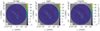 |
Fig. 1 Comparison of the GILDAS standard calibrated (left panel), CASA self-calibrated (middle panel), and GILDAS self-calibrated (right panel) W3 IRS4 continuum data. In each panel, the beam size is shown in the bottom left corner and the pink bar in the top left corner indicates a linear spatial scale of 5000 au. |
2.5 Data products and public release
The data merging of the interferometric and single-dish data and imaging is done in the GILDAS/MAPPING package. The WideX and the corresponding EMIR spectral-line data are smoothed to a common spectral resolution of 3.0 km s−1. The narrow-band and the corresponding EMIR spectral line data are smoothed to a common spectral resolution of 0.5 km s−1. In order to merge the NOEMA and IRAM 30 m data, the task UVSHORT converts the short spacings into a pseudo uv -table and combines them with the NOEMA data.
The deconvolution of the NOEMA continuum, NOEMA spectral line and merged (combined NOEMA + IRAM 30 m) spectral line data is performed in GILDAS/MAPPING using the Clark CLEAN algorithm (Clark 1980) and adopting three different weightings: robust weighting with a robust parameter of 0.1 (θ ~ 0.′′ 4); a robust parameter of 1.0 (θ ~ 0.′′ 6); and natural weighting (θ ~ 1.′′ 0). The stopping criterion for the continuum and broadband spectral line data is set to fres = 0.01, which corresponds to a minimum fraction of 1% of the peak intensity in the dirty image. The stopping criterion for the narrow-band spectral line data is either niter = 5000 (maximum number of iterations) or ares = 0.01, which corresponds to a maximum intensity of 10 mJy beam−1 in the residual image.
Molecules such as CO isotopologues and SO may have extended emission in the merged data products (Mottram et al. 2020). As the Clark algorithm assumes emission from point sources, the CLEANed map may have point-like artifacts. The SDI algorithm (Steer et al. 1984) may improve the CLEANed image in such cases. A comparison between the Clark and SDI algorithms for imaging of the W3 IRS4 region is presented in Mottram et al. (2020). Final data products of the merged broadband spectral line data of molecular lines with potential large-scale emission (13CO 2− 1, SO 65 − 54, H2CO 30,3 −20,2, H2CO 32,2 −22,1, H2CO 32,1 −22,0) CLEANed using the SDI algorithm with robust weighting (robust parameter of 3, θ ~ 0.′′ 6), with a stopping criterion of niter = 25 000 are provided as well. Primary beam correction is applied to the continuum and spectral line data products.
In this study, we use the primary beam corrected NOEMA-only continuum and merged (NOEMA + IRAM 30 m) broadband spectral line data. Both data products are imaged with the Clark algorithm and a robust parameter of 0.1, resulting in the highest angular resolution (θ ~ 0.′′ 4). Table 2 summarizes the properties of the standard and self-calibrated data products for all regions, including the synthesized beam (major axis θmaj, minor axis θmin, and position angle PA), noise of the continuum data σcont, continuum peak intensity Ipeak, and noise in the merged (NOEMA + IRAM 30 m) spectral line data σline,map. The mean map noise of the merged spectral line data is 0.44 K.
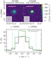 |
Fig. 2 Comparison of the GILDAS standard calibration (left) and GILDAS self-calibration (right) of the W3 IRS4 broadband spectral line data zoomed in toward the position of the continuum peak, shown in the top panels. The integrated intensity of the CH3CN 123 − 113 transition is shown in color. In each panel, the beam size is shown in the bottom left corner and pink bar in the top left corner indicates a linear spatial scale of 5000 au. Bottom panel: CH3CN 123 − 113 spectrum at the position of the W3 IRS4 continuum peak of the GILDAS standard calibrated data (black) and of the GILDAS self-calibrated data (green). The dashed orange line shows the systemic velocity of the region vLSR and the dash-dotted blue lines show the lower and upper velocity limits (vLSR ± 10 km s−1) used for the integrated intensity map shown in the top panel. |
3 Physical structure
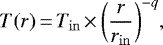
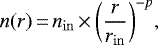
The linear spatial resolution of the CORE sample ranges from 300−2300 au. At this spatial resolution, it is not possible to resolve potential disks surrounding the protostars, but these can be studied and characterized through a kinematic analysis of the line profiles (Ahmadi et al. 2019). However, we do resolve the gas and dust envelopes around individual cores which can be approximated as spherically symmetric objects for which the radial temperature profile T(r) and radial density profile n(r) of the envelope gas can be described by power-laws (e.g., van der Tak et al. 2000; Beuther et al. 2002; Palau et al. 2014):
 (1)
(1)
 (2)
(2)
with Tin = T(rin) and nin = n(rin) at an arbitrary radius rin. The temperature power-law index q and density power-law index p of the core envelopes are important properties of HMSFRs. By studying these quantities with observations, theoretical analytical models on how massive stars form can be constrained.
3.1 Continuum emission
A detailed analysis of the continuum data is presented in Beuther et al. (2018). The updated GILDAS self-calibrated continuum data are shown in contours in Fig. 3. While the sample was selected to be largely homogeneous in luminosity, at an angular resolution of ~0.′′4, a variety of structures can be identified. While some regions appear as isolated single objects (IRAS 23151, AFGL 2591), others show spatially separated cores (IRAS 23033, G108.75, G139.9091, S106, CepA HW2, W3 H2O). There are regions in which fragmentation is observed within an embedded envelope (IRAS 23385, IRAS 21078). Many of the regions have a complex morphology such as filamentary structures and extended envelopes (G084.9505, G094.6028, G100.38, G138.2957, G75.78, NGC 7538 IRS9, S87 IRS1, W3 IRS4).
In this study, we aim to analyze the physical properties and chemical variation across the regions, therefore, we selected a number of positions throughout the different regions. Deriving the column density of all detected species in every single spectrum in each region is computationally expensive and we restrict this method to the analysis of the H2CO and CH3CN temperaturemaps (Sect. 3.2). In order to study the cores and envelopes around forming protostars, we selected positions which have a clear spherically symmetric core-like morphology in the 1.37 mm continuum data which is the case for most regions toward the continuum peak position, but also multiple spherically symmetric objects within a region can be identified (e.g., toward IRAS 23033). In addition, we select positions in the extended envelopes to study potential differences in the chemical abundances. The in total, 120 selected positions are summarized in Table A.1 and marked in Fig. 3. The nomenclature of each position is denoted by the region name and increasing number with decreasing 1.37 mm continuum intensity. For each region, position 1 is toward the 1.37 mm continuum emission peak.
In order to estimate the H2 column density (Sect. 4.1), we require for all positions to be detected in the 1.37 mm continuum (I1.37 mm ≥ 5σcont). The numberof selected positions is higher toward regions with extended envelopes and complex morphologies (e.g., IRAS 21078 and G138.2957) compared to compact regions (e.g., G139.9091 and S106). In this study, we define (in Sect. 3.2) a “core” as an object that shows a radially decreasing temperature profile over at least the width of two beams. In Sect. 5, we apply a 1D physical-chemical model to these defined cores using the observed temperature and density structure analyzed in Sects. 3.2 and 3.3, respectively, and observed molecular column densities (Sect. 4). These positions are labeled as “C” (core) in Table A.1. The remaining positions are locations in the dust envelope and environment around the cores. There are a few positions with a clear spherically symmetric core morphology in the dust emission, but no temperature profile can be derived (e.g., position 1 in S106). Cores with unresolved radial temperature profiles are also not included in this approach. In total we select 120 positions including 22 core positions. The broadband spectra of the 120 positions are shown in Fig. F.1. Table A.1 lists the noise of the broadband spectrum extracted from these positions and the systemic velocity vLSR determined from the C18O 2− 1 line, which may differ from the average region vLSR (listed in Table 1) due to velocity gradients within the region (see Sect. 4.2). In contrast to this core definition, in the analysis by Beuther et al. (2018), “cores” are defined as fragmented objects with emission ≥ 10σcont using the clumpfind algorithm (Williams et al. 1994) and, thus, more cores are found in their analysis.
3.2 Temperature structure
To reliably determine the rotation temperature, Trot, it is required to observe multiple transitions of a molecule. We use formaldehyde (H2CO) and methyl cyanide (CH3CN) as thermometers to determine the temperature structure of the regions, as both have multiple strong and optically thin lines in our spectral setup. The spectral line properties of these molecules are listed in Table B.1.
We model the spectral line emission of these molecules using the eXtended CASA Line Analysis Software Suite (XCLASS, Möller et al. 2017)3. With XCLASS, molecular lines can be modeled and fitted by solving the 1D radiative transfer equation. In the calculation of the Gaussian line profiles optical depth effects are included. For each molecule, the properties of all transitions are taken from an embedded SQlite3 database containing entries from the Cologne Database for Molecular Spectroscopy (CDMS, Müller et al. 2005) and the Jet Propulsion Laboratory (JPL, Pickett et al. 1998), using the Virtual Atomic and Molecular Data Centre (VAMDC, Endres et al. 2016).
The broadband spectral setup includes three strong formaldehyde lines, two of which have the same upper energy level, and one weak transition from the H CO isotopologue. The H2CO and H
 CO are fitted simultaneously in XCLASS using an isotopic ratio calculated from Wilson & Rood (1994): 12C/13C ≈ 7.5 × dgal + 7.6. The 12C/13C ratio is listed in Table 1, for each region. While formaldehyde is a good low-temperature gas tracer at Tkin < 100 K (Mangum & Wootten 1993), at high densities and temperatures, the 30,3−20,2 transition is optically thick and a reliable temperature can no longer be derived from the line ratios with this method (Rodón et al. 2012; Gieser et al. 2019). To determine temperatures at higher densities, we use nine methyl cyanide lines (J = 12−11 and K = 0−8, Eu ∕kB = 69−526 K). In addition, seven lines of the CH
 CN isotopologue are fitted simultaneously (J = 12−11 and K = 0−6, Eu ∕kB = 69−326 K). A detailed discussion of the line optical depth is given in Sect. 4.2.
In XCLASS, each molecule can be described by a number of emission and absorption components. The fit parameter set of each component consists of the source size θsource, the rotation temperature Trot, the column density N, the linewidth Δv, and the velocity offset from the systemic velocity voff. It is possibleto choose a variety of algorithms that can also be combined in an algorithm chain in order to find the best-fit parameters by minimizing the χ2 value. We adopted an algorithm chain with the Genetic and the Levenberg-Marquardt (LM) methods optimizing toward global and local minima, respectively.
For each region, we use the myXCLASSMapFit function to fit the H2CO and CH3CN lines in each pixel within the primary beam. All lines with a peak intensity > 10σline,map are fitted with one emission component. We chose a high threshold of 10σline,map so multiple transitions have a high S/N to accurately determine the rotation temperature. Only a single value can be set as the threshold in the myXCLASSMapFit function, therefore, toward the edges of the primary beam, the temperature estimates are less reliable due to an increase in the noise.
Under the assumption of local thermal equilibrium (LTE), the kinetic temperature of the gas can be estimated from the rotation temperature Tkin ≈ Trot. As HMSFRs have high densities n > 105 cm−3 toward the locations of the protostars, the LTE can be assumed here (Mangum & Shirley 2015). The critical densities,  , for the CH3CN and H2CO lines are ~4 × 106 cm−3 and ~3 × 106 cm−3, respectively (Aul is the Einstein A coefficient and Cul is the collisional rate coefficient). Here, we use Cul measured at 140 K taken from the Leiden Atomic and Molecular Database (LAMDA, Schöier et al. 2005). The H2CO and CH3CN temperature maps of each region are shown in Fig. C.1. The H2CO lines trace the extended low temperature gas at 10−100 K. The CH3CN maps mostly show spatially compact emission tracing the higher temperature gas at >100 K.
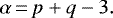
For each selected position (Table A.1), we extract the H2CO and CH3CN radial temperature profile which are binned in steps of half a beam (Δr). In each bin, the uncertainties are computed from the standard deviation of the mean. After a first visual inspection of all radial profiles of the 120 positions, we select all positions with a radially decreasing temperature profile along at least two beams in at least one temperature tracer. With this method, we are able to extract in total 22 positions, which we define as “cores”. The radial temperature profiles of the cores are shown in Fig. 4. In cases where both temperature tracers are detected toward the central core (e.g., IRAS 23033 2), the observed H2CO temperature profile has significantly higher values when compared to CH3CN. As discussed previously, this is due to the high optical depth in these dense regions causing the fit algorithm to converge toward high temperatures. The line optical depth is discussed further in Sect. 4.2.
We fit the profiles with a power-law according to Eq. (1) using the minimum χ2 method to derive the temperaturepower-law index q. We used the CH3CN temperature profile for the fit if it is detected along at least two beams and the H2CO temperatureprofile otherwise. The inner radius is the temperature at a radius of half the beam size rin = Δr. The outer radius rout is chosen as a local minimum, when Trot (rout) < Trot (rout + Δr) and Trot (rout) < Trot (rout + 2Δr). In cases where the outer radii of nearby cores overlapped or the 2D temperature distribution would become highly asymmetric, we reduced the outer radius. The outer radii are also marked in Fig. 4. The fit results for q, rin, rout, and Tkin (rin) are summarized in Table 3 for each core.
A histogram of the temperature power-law index q is shown in Fig. 5. Most of the data points are distributed between 0.1 and 0.6, but three outliers are located at q > 0.9. A Gaussian fit to the data with q = 0.1−0.6 yields an average value of q = 0.4 ± 0.1, which is in very good agreement with theoretical predictions (Emerson 1988; Osorio et al. 1999; van der Tak et al. 2000) and observations (e.g., Palau et al. 2014, 2020). The issue of optical depth of the H2CO lines and CH3CN being only detected toward the densest parts result in the high uncertainties and spread in q. We observe a broad range of q with shallow profiles (q = 0.1) up to steep profiles (q = 1.5). In order to study if q is constant for all high-mass cores or if the range of q is real, observations of more cores are required. Osorio et al. (1999) and van der Tak et al. (2000) suggest steeper values for q on scales < 2000 au. In addition, the temperature maps and radial profiles are 2D projected, whereas the real 3D profile may be more complicated.
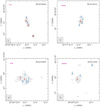 |
Fig. 3 1.37 mm continuum emission. The selected positions analyzed in this paper (summarized in Table A.1) are marked and labeled in red (core positions) and blue (all remaining positions). The dashed black contours show the − 5σcont emission andthe solid black contours start at 5σcont with contoursteps increasing by a factor of 2 (e.g., −5, 5, 10, 20, 40, 80,...σcont; see Table 2 for values of σcont for eachregion). In each panel, the beam size is shown in the bottom left corner and the pink bar in the top left corner indicates a linear spatial scale of 5000 au. The field of view in each region is adjusted to only show the area with significant emission (≥ 5σcont), and for regions with wide-spread emission, the primary beam is indicated by a black circle. |
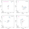 |
Fig. 3 continued. |
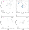 |
Fig. 3 continued. |
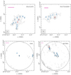 |
Fig. 3 continued. |
 |
Fig. 3 continued. |
3.3 Density structure
In contrast to the merged (NOEMA + IRAM 30 m) spectral line data, the 1.37 mm continuum NOEMA data suffer from missing flux due to the lack of short-spacing information. Therefore, it is difficult to reliably derive radial intensity profiles in the final images that are required to determine the density structure. This issue can beminimized by analyzing instead the complex visibilities of the 1.37 mm continuum data in the uv -plane (Adams 1991; Looney et al. 2003; Beuther et al. 2007b; Zhang et al. 2009). Assuming spherical symmetry, the power-law index of the complex visibility profile α is related to the density power-law index of the radial density distribution p by (Looney et al. 2003):
 (3)
(3)
For each core position, the phase center is shifted to this location. The remaining cores within a region are fitted as a point source + circular Gaussian (to account both for the compact and the extended emission) and subtracted using the UV_FIT task in GILDAS. With this approach, the blending of nearby cores in the visibility profiles within a single region can be minimized. The azimuthally averaged complex visibilities, computed using the UVAMP task in MIRIAD (Sault et al. 1995), are binned in steps of 20 kλ. The radial visibility profiles are shown in Fig. 6. The uv distances range from ~ 20−800 m corresponding to spatial scales of ~103−105 au at distances of a few kpc. We apply a power-law fit to the data in order to derive the power-law index α. The density power-law index p is calculated according to Eq. (3), taking into account the temperature power-law index q derived in Sect. 3.2. The results for α and p for all cores are summarized in Table 3.
Most of the visibility profiles (Fig. 6) can be described by a single power-law. The higher scatter at large uv distances is due to the fact that less data is available at long baselines. For IRAS 23385, the visibility profiles of core 1 and 2 do not follow a simple power-law. Toward smaller spatial scales (< 104 au), the profiles are steeper. This could be due to the fact that even though the contribution of nearby cores is minimized by subtracting a point source + circular Gaussian, in the case of IRAS 23385, it is not possible to clearly distinguish the contribution of both cores, which are embedded within a common dust envelope.
The histogram of the density index p is shown in Fig. 7. Using the observationally derived values of q, the power-law index ranges from 1.4−2.4. Fixing the temperature power-law index q to the mean value of 0.4 and calculating p with the results from the uv-analysis, the distribution of p gets narrower, peaking at p = 2.0−2.1. A Gaussian fit to this distribution yields a mean of p = 2.0 ± 0.2. The results of the derived physical structure of these 22 cores are discussed in detail in Sect. 6.1.
4 Molecular gas content
In this section, we analyze the chemical content of the molecular gas toward the 18 CORE HMSFRs by studying the molecular column densities derived toward the 120 positions. The column density of molecular hydrogen N(H2) is derived from the 1.37 mm dust continuum emission (Sect. 4.1). In addition, molecular column densities are derived from the merged spectral line data with XCLASS by fitting the emission lines assuming LTE conditions (Sect. 4.2). Spectra extracted toward the selected positions are shown in Fig. F.1. In total, we consider 11 species among a total of 16 isotopologues that are commonly detected within the 4 GHz spectral bandwidth of the broadband WideX correlator: 13CO, C18O, SO, OCS, SO2, DCN, H2CO, HNCO, HC3N, CH3OH, CH3CN. A spectral resolution of3 km s−1 is not sufficient to study the line widths and kinematic properties in detail, but sufficient to derive molecular column densities, N.
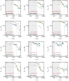 |
Fig. 4 Radial temperature profiles of the 22 cores. Each panel shows the binned radial temperature profile derived from the H2CO (green) and CH3CN (blue) temperature maps shown in Fig. C.1. The data points used for the radial profile fitare shown by corresponding colored errorbars, the data points excluded from the fit are indicated by grey errorbars. The outer radius of the temperature fit is shown by the vertical purple dash-dotted line. The inner unresolved region is shown as a grey-shaded area. The linear fit and the ± 1σ uncertainty are shown by the solid and dashed red lines, respectively. |
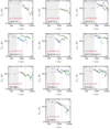 |
Fig. 4 continued. |
4.1 Molecular hydrogen and core mass estimate
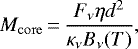
The beam-convolved molecular hydrogen column density N(H2) toward all 120 positions and mass calculation of the 22 cores Mcore can be derived from the continuum intensity Iν assuming that the emission is optically thin (Hildebrand 1983):
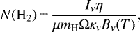 (4)
(4)
 (5)
(5)
with a gas-to-dust mass ratio η = 150 ( /
/ , with
  and
and  ; see Table 1.4 and 23.1 in Draine 2011, respectively), mean molecular weight μ = 2.8 (Kauffmann et al. 2008), hydrogen mass mH, beam solid angle Ω, dust opacity κν = 0.9 cm2 g−1 for dust grains with a thin icy mantle at a gas density of 106 cm−3 at 1.3 mm (Ossenkopf & Henning 1994), the Planck function Bν (T), and distance d. Fν is the integrated intensity of each core within the outer radius, rout.
We use Tkin for the temperature, T, in the Planck function taken from the thermometers H2CO and CH3CN, assuming LTE conditions (Tkin ≈ Trot). If the spectrum is extracted from a core position, Tkin is taken from the radial temperature fit described in Sect. 3.2 with T = Tkin(rin) (see Table 3). If the spectrum is extracted from a position not corresponding to a core, the kinetic temperature is computed from Trot (CH3CN) if detected or from Trot (H2CO) otherwise. If there is no temperature tracer detected toward the position, we adopt a lower limit of Tkin = 20 ± 10 K, as the lowest derived rotation temperatures range between 10−30 K.
In order to validate that the assumption of optically thin dust emission is valid, the continuum optical depth,  , is computed for each position (for a derivation of the equation, see Appendix A in Frau et al. 2010):
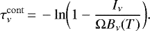 (6)
(6)
The kinetic temperature, Tkin, molecular hydrogen column density, N(H2), and continuum optical depth,  , are listed in Table A.1 for all 120 positions. The uncertainties of N(H2) and Mcore are calculated based on the assumption of Gaussian error propagation and include the uncertainty of the continuum intensity, with an estimated 20% flux calibration uncertainty (Beuther et al. 2018) and uncertainty of the derived rotation temperature, ΔTkin (listed in Table A.1). The optical depth,
  , is ≪1 toward most positions, so optically thin dust emission can be assumed here and the H2 column density and core mass calculation provide reliable results. The only exceptions with
  are positions 1 and 2 of the W3 H2O region, which corresponds to the W3 OH UCHII region (see also Ahmadi et al. 2018). The molecular hydrogen column density N(H2) has a mean value of 1.5 × 1024 cm−2, ranging from 2.7 × 1022 cm−2 up to 2.8 × 1025 cm−2. The core masses, Mcore, are listed in Table 3. We find a mean core mass of 4.1 M⊙ in a range between 0.3 M⊙ and 11.6 M⊙. As discussed previously, due to missing short-spacing information, both N(H2) and Mcore should be considered as lower limits. However, the high core masses indicate that they are harboring protostars that will eventually end up as massive stars.
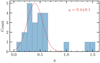 |
Fig. 5 Histogram of the temperature power-law index q. The red line shows a Gaussian fit to the data points for q = 0.1−0.6. |
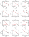 |
Fig. 6 Radial visibility profiles of the 1.37 mm continuum emission of the 22 cores. The black data points show the radial profile of the averaged complex visibilities of the 1.37 mm continuum as a function of uv distance (bottom x-axis) and of the corresponding linear scale (top x-axis). The linear fit and the ±1σ uncertainties are indicated by the solid and dashed red line, respectively. |
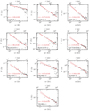 |
Fig. 6 continued. |
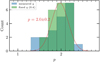 |
Fig. 7 Histogram of the density power-law index p. The density power-law index derived with the measured values of q for each core are shown in blue. In green, the results for p calculated with a fixed temperature index (q = 0.4) for all cores are shown. The red line shows a Gaussian fit to the green histogram. |
4.2 Spectral line modeling with XCLASS
We use the spectral line data of the CORE project to derive molecular column densities of 11 different species using the XCLASS software. A description of the XCLASS software is presented in Sect. 3.2. Using the myXCLASSFit function, individual spectra are fitted species by species with one emission component to derive the molecular column density, N.
A spectrum is extracted from the merged spectral line data for each position listed in Table A.1. The noise σline in each spectrum is computed in a line-free range from 219.00 to 219.13 GHz. Compared to the average map noise σline,map listed in Table 1, the noise in each spectrum σline may have higher or lower noise values since the noise distribution is not uniform within the primary beam. The systemic velocity vLSR is determined by fitting the C18O 2− 1 transition and may differ from the global vLSR listed in Table 1 due to velocity gradients in the region, hence, it allows us to employ a narrow parameter range for voff and so fitting strong nearby emission lines is avoided. The systemic velocity vLSR and noise σline are listed in Table A.1 for each position.
All molecules and their corresponding transitions that are fitted with XCLASS are listed in Table B.1. Lines which are blended with transitions of other detected species (at a resolution of 3 km s−1) are also listed, but excluded from the fit. For most molecules, only the rotational ground-state level v = 0 can be detected in our spectral setup. For SO2 and HC3N vibrationally excited levels (vx > 0) are present and for CH3OH torsionally excited lines are detected (vt = 1). The following species for which we observe multiple isotopologues are fitted simultaneously: OCS and O13CS; SO2 and 34SO2; H2CO, and H CO; HC3N and HCC13CN; CH3CN and CH
 CN. The isotopologue ratios are summarized in Table 1 and are calculated either from Wilson & Rood (1994) (12C/13C ≈ 7.5 × dgal + 7.6) or taken from references within (32S/34S ≈ 22). The uncertainties of these isotopic ratios are high due to a large scatter of the data points. However, we do not observe a sufficient number of strong isotopic lines to measure it more precisely. We did not fit 13CO and C18O simultaneously because the 13CO 2− 1 line has a high optical depth (see Table B.1).
We use an algorithm chain with the Genetic and Levenberg-Marquardt (LM) methods and to estimate the uncertainties of the fit parameters, we used the MCMC error estimation algorithm afterward. The following criteria are applied to the fitted model spectrum and column density,  , of each species in order to determine bad fits: (1) model spectra with a peak intensity < 3σline; (2) the upper error of the column density ΔNupp is converging toward high values (ΔNupp > 10 × N); and 3) the lower error of the column density is not constrained ΔNlow = 0 cm−2. With these three criteria, weak and unresolved lines are automatically discarded and we use the best-fit value of N only as an upper limit.
The column densities, N, for all species fitted with XCLASS and their uncertainties derived with the MCMC error estimation algorithm are summarized in Tables E.1–E.3 for all positions. Histograms of the logarithmic column density distributions including N(H2) are shown in Fig. 8, with the mean and standard variation of the column density noted in each panel (upper limits are not included). The logarithmic bin width is set to 0.5. Separate histograms of the core and non-core populations are shown in the same panels. However, as discussed in Sect. 2, for the spectral line data, we have short-spacing information, while we do not have this for the continuum data, hence we systematically underestimate the H2 column density.
There are species with a distribution having a clear column density peak (e.g., H2, 13CO, C18O, SO, DCN, H2CO, HNCO). Other species have a double-peaked distribution with a clear separation between the core and the remaining positions (e.g., OCS, HC3N, CH3OH, CH3OH;vt = 1, and CH3CN). In these cases, the column density is enhanced by a factor of ~10−100 toward the core positions. There are not enough data points for the SO2, HC3N;v7 = 1, HC3N;v7 = 2 to draw any conclusions about the distribution, however, they are detected mostly in the densest regions toward core positions. In general, high column densities are found toward core positions and low column densities are found toward the remaining positions.
To account for the fact that toward the core positions the column density is expected to be higher in a higher density region, we show relative abundance N(X)/N(C18O) histograms in Fig. D.1 (upper limits are not included). Assuming that both species trace the same emission region, the relative abundances are independent of the absolute column density value, which differ from region to region and from core to core. Normalized to N(C18O), most species have a single-peaked distribution. Exceptions are OCS, HNCO, HC3N, CH3OH, and CH3CN with double-peaked distributions indicating that high temperature gas-phase chemistry has a big impact on these N-bearing molecules by increasing their abundances. However, in general there is still a clear difference between core positions (high abundance) and non-core positions (low abundance). The fact that larger molecules have a clearer distinction between the core and non-core positions, while for simpler species it is less obvious (e.g., 13CO and DCN), hints that the emission of COMs is associated with the cores while simple molecules are abundant in envelope as well. The difference of the core and the remaining positions indicates that the high densities and possible energetic processes around the protostars have a strong impact on the molecular abundances in the gas phase (e.g. through protostellar outflows, shocks, disk accretion, and strong radiation from the protostars). Correlations of the derived column densities are discussed in Sect. 6.3.
Observed and XCLASS modeled spectra are shown in Fig. F.1 for all positions. The computed optical depth for all fittedlines as a function of rest-frequency is shown as well. Even though the sample was selected to be at a similar evolutionary stage (HMPO/HMC), the number of emission lines in the observed spectra vary from region to region, but also within a region. Typical hot core spectra are observed for the positions AFGL 2591 1, CepA HW2 1, G75.78 1, W3 H2O 1, and W3 H2O 2. Many weak emission features are detected in the spectra at a ~ 2−3σline level originating from COMs. These COM emission features are difficult to fit as the transitions are weak, have similar upper energy levels Eu ∕kB, and are blended at a spectral resolution of 3 km s−1, so they were excluded from this analysis. A detailed study of the integrated line emission (including line stacking of weak COM emission lines) will be presented in a future study (Gieser et al. in prep.). Fewer species are detected in spectra toward the non-core positions. In contrast to the line-rich sources, there are several sources that show only a handful of emission lines mainly from CO-isotopologues, SO, and H2CO even toward the continuum peak positions. The line-poor regions are G139.9091, G138.2957, S87 IRS1, and S106. In the case of IRAS 23033,core 1 has a line-poor spectrum, whereas for core 2 and 3, which are embedded in a common envelope, significantly more emission lines are detected. These cores either could be at different evolutionary stages or they are embedded in an inhomogeneous local radiation field. The former can be investigated by applying a chemical model to the observed column densities and by estimating the chemical ages of the regions. We investigate this possibility in the next section.
The mean and maximum line optical depth,  and
and  , computed for each fitted transition with XCLASS are summarized in Table B.1. The 13CO 2− 1 transition has the highest mean optical depth with
  , but for most other species and transitions, the mean line optical depth is < 1, so the column density and temperature determination should be reliable, especially when many transitions of a molecule are fitted simultaneously. The mean optical depth of the H2CO 30,3 −20,2 transition is a factor of four higher than the remaining two transitions. When the 30,3 −20,2 transition is optically thick, temperature estimates depending on the line ratios are difficult to determine with the remaining two optically thin lines as they have similar upper energy levels (68 K). In 23 out of the 118 spectra where H2CO was detected and fitted with XCLASS, the calculated optical depth of the 30,3 −20,2 transition is τline > 1.
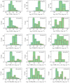 |
Fig. 8 Column density histograms. The H2 column density is derived from the 1.37 mm continuum emission and the remaining molecular column densities are derived with XCLASS. Column density histograms of all 120 positions are shown in green bars (upper limits are not included). Separate column density histograms of the core and the remaining positions are indicated by the dash-dotted red and dashed blue lines, respectively. |
5 Physical-chemical modeling of the cores
The continuum data of the CORE sample show a large diversity in fragmentation properties (Beuther et al. 2018) and our analysis (shown in Sect. 4) demonstrates that the composition of the molecular gas varies within as well as between the regions: some have a rich plethora of molecular lines, while others have line-poor spectra. This diversity of physical and chemical properties could be explained by a number of reasons. Magnetic fields or different initial density structures could explain the variety in fragmentation properties (Beuther et al. 2018). Different initial conditions in, for instance, the large-scale kinematics and mass distribution might also have an effect on the molecular abundances. To investigate whether the observed variation of the physical and chemical properties of the cores may be due to the fact that the CORE regions have different ages, we model the chemical evolution of the 22 cores in the following.
5.1 MUSCLE setup
We applied the physical-chemical model to the physical properties and molecular column densities of each core determined from the CORE 1mm observations in order to estimate the chemical ages. MUSCLE (MUlti Stage ChemicaL codE) has previously been successfully applied to the CORE pilot regions NGC 7538 S and NGC 7538 IRS1 (Feng et al. 2016) as well as the CORE region AFGL 2591 (Gieser et al. 2019). The model comprises spherically symmetric physical structures. The temperature and density profiles of the cores are described by power-laws up to the outer radius, rout, with index q and p, respectively (see Eqs. (1) and (2)). At an inner radius, rin, and further in, the density and temperature reach a constant value. We adopt 40 logarithmic grid points for the radial profiles.
On top of this static physical structure, the time-dependent gas-grain chemical network ALCHEMIC (Semenov et al. 2010)computes the abundances of hundreds of atomic and molecular species using thousands of reactions. A detailed description of MUSCLE can be found in Gerner et al. (2014, 2015). We adopt most of the model parameters from the AFGL 2591 case study described in Gieser et al. (2019), which yielded a good estimate of the chemical age of this hot core compared to literature estimates. A summary of the input parameters is listed in Table 4. In contrast to the AFGL 2591 case-study, we use a higher value for the cosmic ionization rate ζCR based on a study of multiple HMSFRs by Indriolo et al. (2015). These authors find that ζCR is constant at a Galactic radius > 5 kpc and with all the CORE regions at Galactic distances >7 kpc (Table 1), we use a constant value of 1.8 × 10⁻¹⁶ s−1. By setting the extinction at rout to Av = 10mag, the core is shielded from the interstellar ultraviolet radiation field.
For each of the 22 cores, we run a physical-chemical model with MUSCLE. The input are the H2 column density (Sect. 4.1) and all molecular column densities derived with XCLASS (Sect. 4.2). The CO column density N(CO) is calculated from N(C18O) as C18O is less optically thick than 13CO (Table B.1) and, hence, more reliably fitted in XCLASS. For each region, we calculate the 16O/18O isotopic ratio according to Wilson & Rood (1994): 16O/18O ≈ 58.8 dgal + 37.1. The 16O/18O ratio is listed in Table 1 for each region. For HC3N and CH3OH, we compute the mean column density of the rotational ground state and vibrationally or torsionally excited states for the MUSCLE input. Molecular column densities, for which only upper limits could be determined, are also set as upper limits in MUSCLE. We set the temperature structure of the model core to the observed temperature profile (Sect. 3.2) and used the density power-law index derived from the continuum visibility analysis (Sect. 3.3).
Two undetermined model parameters remain. We do not know, for one, how evolved the cores are, described by the chemical age, τchem, and second, what the initial chemical composition of the parental molecular cloud/clump was. Due to the fact that the CORE regions are far more evolved than typical cold IRDCs and the physical structure of each model stage is static, we have to define a sensible initial condition for the chemical composition. The initial conditions we apply are based on a study of 59 HMSFRs using single-dish observations (Gerner et al. 2014, 2015). These HMSFRs were classified according to their evolutionary stage (IRDCs, HMPOs, HMCs, and UCHII regions) and a template was created from the average column densities for each evolutionary stage. The four template stages were modeled using MUSCLE to create average abundances for all molecular and atomic species and to estimate a mean chemical age of each evolutionary stage. The properties of their template IRDC, HMPO, and HMC model are summarized in Table 4. Following the convention by Gerner et al. (2014, 2015), the chemical age τchem is 0 yr when the gas density reaches 104 cm−3.
Based on the temperature profiles of the 22 cores, we can assume that they lie somewhere between the HMPO and early UCHII stage, since the average temperatures around cores are too high to be classified as IRDCs (T ~ 20 K). There are a few known UCHII regions with strong free–free emission at cm wavelengths resolved in the CORE data. In W3 H2O, the Westernpart (around position 1 and 2 in Fig. 3) is the UCHII region W3 OH. In W3 IRS4, the Southern ring-like structure is an UCHII region as well (Mottram et al. 2020). However, for the W3 OH UCHII region we do not find a clear radial decreasing temperature profile and toward the W3 IRS4 UCHII region no H2CO or CH3CN line emission is detected at a 10σline,map level to estimate the kinetic temperature. The S106 region is a UCHII as well, for which we do not detect neither H2CO nor CH3CN emission around the compact core. This already suggests that toward this later stage, the molecular richness in these regions is decreased.
To test which initial conditions (see Table 4) fit best to the observed molecular column densities, we model each of the 22 cores with initial abundances after an initial IRDC phase (referred to as the HMPO model), after an initial HMPO phase (referred to as the HMC model), and after an initial HMC phase (referred to as the UCHII model). While most cores are unlikely to have formed a strong UCHII region yet, we include the UCHII model, as the observations in Gerner et al. (2014, 2015) have large beam sizes (11″ and 29″), and UCHII regions may have contamination from less evolved line-rich objects, which are blended into the single-pointing spectra. It is not our aim to classify the cores into these evolutionary stages, but to find sensible initial chemical conditions as an input for our physical-chemical modeling. For example, an evolved HMC that is more evolved than the template HMC from Gerner et al. (2015) would best be described best by the UCHII model in our nomenclature.
For each model, the chemical evolution, τmodel, runs up to 100 000 yr in 100 logarithmic time steps. In each time step, the computed radial abundance profiles are converted into beam-convolved column densities with the beam size fixed to the mean synthesized beam of the observations. The best-fit model is determined by a minimum χ2 analysis by comparing the modeled and observed column densities in each time step and for all three adopted initial condition models. Applying this physical-chemical model allows us to estimate the chemical age.
MUSCLE input parameters.
5.2 Chemical ages
The best-fit chemical age τchem, χ2, and percentage of well-modeled molecules are shown in Table G.1 for each initial abundance model and core. Gerner et al. (2014) estimated that chemical ages are uncertain by a factor of between two and three and that the modeled column densities are uncertain by a factor of ten. But this depends on the number of modeled molecules, but also cores embedded in complex dynamic environments are harder to fit with our model. The chemical age τchem is the sum of the time of the initial abundance model and τmodel, so for the HMPO model: τchem = τIRDC + τmodel, for the HMC model: τchem = τIRDC + τHMPO + τmodel; and for the UCHII model: τchem = τIRDC + τHMPO + τHMC + τmodel.
For some cores, multiple initial condition models have a similarly low χ2 (e.g., the HMPO and UCHII model for core 1 in IRAS 23033). In these cases, we cannot constrain the chemical age well. Comparing the lowest χ2 model with the remaining initial condition models, if the χ2 difference is less than 5%, only chemical age ranges spanning over these models are further considered. Table 3 shows the chemical age τchem for models with a clear lowest χ2 initial condition model or a time range in chemical age for cores with multiple best-fit initial condition models. The estimated chemical timescales τchem of the cores vary between ~20 000 and 100 000 yr within the regions of the CORE sample with a mean of ~60 000 yr. The youngest core being G084.9505 1 and the oldest core being G108.75 2.
A comparison of the best-fit modeled and observed column densities for all cores is shown in Fig. 9. For most cores, the model underestimates the H2CO and CH3OH column densities as compared to the observed values. This can be explained by the fact that the quasi-static model does not sufficiently take into account the warm-up stage from 30−80 K where surface chemistry on the dust grains plays an important role and where these two molecules are formed by subsequent hydrogenation of CO. These discrepancies between modeled and observed H2CO and CH3OH column densities have already been noticed by Gerner et al. (2014) in their template HMPO stage modeled with MUSCLE. They explain that this is due to the fact that the formation route of H2CO consists of grain-surface as well as gas-phase chemistry which are both time-dependent and not correctly implemented in the chemical models. This results in the over and underproduction of these species, which is also the case in our modeling results, shown in Fig. 9.
Large discrepancies between the modeled and observed column density exist also for the SO molecule for which the model overproduces the SO column density by a factor >10 for many cores (e.g., IRAS 23033 core 1, 2, and 3). This overproduction in SO is seen in all three initial condition models, but in most cases, other modeled S-bearing species (OCS and SO2) are modeledwell. The applied initial chemical conditions based on the Gerner et al. (2015) models also included S-bearing species (SO, CS, and OCS). Their initial IRDC stage model started with elemental abundances and only H2 in molecular form taken from the low metals set of Lee et al. (1998). But in order to fit the IRDC phase accurately, Gerner et al. (2015) had to increase the initial elemental S abundance from 8 × 10⁻⁸ to 8 × 10⁻⁷ (w.r.t. H). However, an overproduction of SO is also seen in their best-fit HMPO, HMC and UCHII models. This might be connected to a poorly understood chemistry of the reactive SO molecule, as also in their models the remaining S-bearing species can be reproduced properly. In addition, as only one SO transition is covered in our spectral setup, which can typically be optically thick (Table B.1 and Fig. F.1), we may underestimate the observed SO column density. This might partially explain the differences between the modeled and observed SO column density.
With multiple cores resolved within a region, it is possible to study how the chemical timescale τchem varies across small spatial scales. In the IRAS 23033 region, core 1 seems to be more evolved (~ 30 000−100 000 yr), even though the spectrum is line-poor (see Fig. F.1) compared to the spectra of core 2 and 3 which are embedded in a common envelope (see Fig. 3) and for which we estimate similar chemical timescales of ~20 000 yr. Core 1 and 2 in CepA HW2 have a chemical age of ~80 000 yr and ~20 000−90 000 yr, respectively. The cores are very close (~2300 au), but within our sensitivity limit, these cores are not embedded in a common envelope, but have very steep density profiles (p ≳ 2). In IRAS 21078, core 1 and 2 have a chemical age of ~60 000−90 000 yr and ~50 000 yr, respectively, suggesting a small age gradient. The cores are embedded within a common envelope and have small projected separations. Core 3 and 4 in W3 H2O have a chemical age of ~90 000 yr and ~ 20 000−90 000 yr, respectively. In the IRAS 23385 region, core 1 is younger (~50 000 yr), while core 2 is estimated to be much older (~100 000 yr). In G108.75 a large difference between the chemical ages of core 1 (~20 000 yr) and core 2 (~110 000 yr) is estimated. The cores have a separation of ~20 000 au, but have the same systemic velocity (Table A.1). A strong external radiation field or complex dynamics could be the reason for this large chemical age difference.
One of the limitations of MUSCLE is that the physical structure (radial temperature and density profiles) is static within each evolutionary stage (IRDC, HMPO, HMC, and UCHII). In reality, these properties do change on timescales smaller than the chemical timescales derived here; in addition, the dynamics (e.g., gas inflow) are important factors to consider. Currently, 3D time-dependent physical models in combination with a full chemical network are computationally expensive. Therefore, we use the approach of our quasi-static physical model by considering the four different evolutionary stages. More sophisticated physical-chemical models in the future are required to include 3D gas dynamics and the evolution of the density and temperature structure. In addition, a larger number of molecular column densities would better constrain the model parameter space.
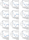 |
Fig. 9 Comparison of the observed and modeled column densities shown in red and blue, respectively. Upper limits are indicated byan arrow. |
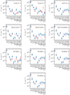 |
Fig. 9 continued. |
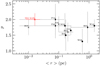 |
Fig. 10 Literature comparison of the density index p at different core or clump sizes, ⟨r⟩. Studies based on interferometric observations are marked by a “ × ”, (sub)mm single-dish observations by a “•”, multi-wavelength observations by a “♦”, and mid-infrared observations by a “○”. References. M02: Mueller et al. (2002); B02: Beuther et al. (2002); H03: Hatchell & van der Tak (2003); W05: Williams et al. (2005); B07: Beuther et al. (2007b); Z09: Zhang et al. (2009); B12: Butler & Tan (2012); G13: Giannetti et al. (2013); P14: Palau et al. (2014); W16: Wyrowski et al. (2016); P20: Palau et al. (2020). |
6 Discussion
6.1 Physical structure of high-mass star-forming cores
Various methods were applied in the literature to observationally derive the density profiles of envelopes in HMSFRs (e.g., summarized in Table 6 in Gieser et al. 2019). Some of these studies are based on observations with single-dish telescopes with beam sizes > 10″ tracing the clump-scale envelope, while interferometric observations trace the core-scale envelope. We selected studies in the literature for which the density structure was determined for a sample of cores or clumps and we extracted the typical sizes ⟨ r⟩ from their studies. Theresults in comparison with our study are shown in Fig. 10. At scales of 1 pc down to 0.01 pc, it seems that the density index p lies between 1.7 and 2.0, which is close to the values inferred in low-mass star-forming regions (Motte & André 2001). To investigate this further, we observed the CORE regions with the NIKA2 instrument at the IRAM 30 m telescope and an analysis of the density structure at clump-scales will follow (Beuther et al., in prep.).
The observationally-derived density and temperature profiles (q = 0.4 ± 0.1 and p = 2.0 ± 0.2) are in agreement with theoretical studies of HMSF, but the physics of how massive stars form is still not fully understood. Currently, theoretical models propose the formation of high-mass stars through: a monolithic collapse of turbulent cores (McKee & Tan 2002, 2003); protostellar collisions and coalescence in dense clusters (Bonnell et al. 1998; Bonnell & Bate 2002); or competitive accretion in clusters (Bonnell et al. 2001; Smith et al. 2009; Hartmann et al. 2012; Murray & Chang 2012). The density and temperaturestructure are important parameters of the initial cloud and proceeding clump and core scales. For example, early star formation models by Shu (1977) and Shu et al. (1987) that model the gravitational collapse of an isothermal sphere find that p = 2 in the outer envelope and p = 1.5 in the inner region where the gas is free-falling onto the central region. McLaughlin & Pudritz (1996, 1997) used a logatropic equation of state and a non-isothermal sphere and find that at an initial density profile of p = 1, the profile steepens to p = 1.5 after the collapse. In the turbulent core model by McKee & Tan (2002, 2003) the authors assume p = 1.5 based on observational constraints. In Bonnell et al. (1998) the density profile in the outer region has the form p = 2 and a shallower, near-uniform profile in the central region. Murray & Chang (2012) explore their models by varying p from 0 (uniform), 1, and 2 (isothermal).
The density structure is important for the physical and chemical evolution of HMSFRs. It is therefore important to quantify the initial density profile on cloud to clump and cores scales and how it changes with time. While theoretical models usually do not predict, but rather assume a given density profile, observations of HMSFRs on different scales can help to narrow down the parameter space (see Fig. 10). Hydrodynamic simulations reported by Chen et al. (2021) investigate how changes of p in giant molecular clouds with an initial radius of 20 pc affect massive star cluster formation. They find that for steep density profiles, p = 2, there is a centrally concentrated cluster, while for shallower profiles, hierarchical fragmentation occurs. Hydrodynamic simulations from Girichidis et al. (2011) show that massive protostars form only in clouds with a density index of p = 1.5 or p = 2.0, while for uniform or Bonnor-Ebert-like profiles, a large fraction of low-mass stars form. The authors found that turbulence and the initial density profile are important aspects for the evolution of the cloud and the formation of clusters.
We study the correlations of all core properties shown in Table 3 using the Spearman correlation coefficient r. This statistical tool can be used to check if two data sets have a positive correlation (r = 1), negative correlation (r = −1), or no correlation (r = 0). We assume that a high correlation exists if r > 0.8. For example, Feng et al. (2020) finds a negative correlation for the H2 column density and dust temperature for cold high-mass clumps using the Spearman correlation coefficient, r. A big advantage compared tothe Pearson correlation coefficient is that linear, as well as nonlinear, correlations are considered in the calculation of r. In addition, we add the M/L ratio of the region listed in Table 1 in Beuther et al. (2018) as a parameter for each core. However, the interpretation is difficult as multiple cores within a region have the same M/L ratio. A mean chemical age is used in the computation of r for cores for which only a time range can be estimated (Table 3).
The results for the correlation coefficient, r, are shown in Fig. 11, where all pairs with a correlation > 0.8 are highlighted. Unfortunately, a small sample of only 22 cores does not allow us to find many strong correlations. Observations of many HMSFRs at core-scales are required to study these relations in a better statistical way, which will be possible, for example, with the ALMAGAL survey, an ongoing ALMA large program observing more than 1 000 HMSFRs. A high correlation is found between the inner and outer radius, which is due to the fact that weare resolution-limited and the regions are located at different distances. The correlation between p and α is due to Eq. (3). However, we find a strong negative correlation between the M/L ratio and the H2 column density of the cores, so more evolved cores have a higher beam-convolved H2 column density. The M/L ratio, proposed to be a good tracer of the evolutionary stage, is investigated in the following section.
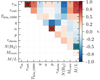 |
Fig. 11 Spearman correlation coefficient r for the derived physical and chemical core parameters listed in Table 3. Values higher than 0.8 are marked by a green circle. |
6.2 M/L ratio as a tracer of evolutionary trends
Sridharan et al. (2002) found that the distance-independent ratio M/L of UCHII regions is lower (~0.005) than the ratio of HMPOs (~0.025), as UCHII regions are more evolved and thus more luminous. This has also been confirmed by observations of large samples of HMSFRs, for instance, by Molinari et al. (2008, 2010, 2016, 2019); Maud et al. (2015); Urquhart et al. (2018). In Fig. 12 we plot the region-average M/L ratio taken from Table 1 in Beuther et al. (2018) against the estimated chemical ages τchem. The chemical timescale and a factor 2 uncertainty is shown for cores with a clear best-fit model. For cores with estimated chemical age ranges, the mean chemical age are shown with error bars spanning over the time range. The luminosities L have uncertainties on the order of ~30% (Mottram et al. 2011b) and the masses M calculated in Beuther et al. (2018) are expected to be uncertain within a factor of 3. We also show the average M/L ratio for HMPOs and UCHII regions derived by Sridharan et al. (2002). We corrected the M/L ratios of Sridharan et al. (2002) by a factor of 0.5, as M was taken from Beuther et al. (2002) where the reported values for M were lower by a factor of 2 (Beuther et al. 2005). The cores G108.75 1 and 2 are excluded here, because no consistent continuum data is available to reliably derive the mass (Beuther et al. 2018). There is a tendency such that the older cores have a lower M/L ratio. However, as the M/L ratios are determined on much larger scales and we resolve multiple cores within each region, it is difficult to compare these properties.
Estimating the chemical ages with MUSCLE shows that a line-rich spectrum does not have to imply that a core is more evolved compared to a core with a line-poor spectrum. For example, the line-poor core 1 in IRAS 23033 is estimated to be older than the line-richer cores 2 and 3. When a hot core evolves to become an UCHII region, the strong protostellar radiation destroys molecules. Hence line-poor spectra can be found at early and at late evolutionary stages. Observations of more species would be helpful to better constrain the chemical model.
We are not able to derive radial temperature profiles from the temperature maps of G138.2957, G139.9091, and S106 (Fig. C.1). In G139.9091 and S106 there is no emission at the adopted 10σline,map level. There is diffuse emission of H2CO in G138.2957, but it is too diffuse to derive a radial temperature profile. The spectra of these regions are line-poor and only simple species are detected (13CO, C18O, SO, H2CO, see Fig. F.1). Based on the shape of the 1.37 mm continuum emission, G139.9091 and S106 have isolated cores with no significant envelope emission, while G138.2957 has diffuse dust emission (Fig. 3). Thereforeone may conclude that G139.9091 and S106 are already more evolved and probably have τchem > 100 000 yr. S106 is a well studied bipolar HII region (e.g., Roberts et al. 1995; Schneider et al. 2007). G139.9091 is associated with a HII region as well (e.g., Kurtz et al. 1994; Purser 2017; Obonyo et al. 2019). G138.2957 could be in a very young strongly depleted phase with τchem < 20 000 yr or could be an evolved region and the diffuse emission is due to the disruption by the protostellar radiation. With observations of G138.2957 at 5.8 cm and 20 cm, a core component with an associated synchrotron jet is seen toward the location of the 1.37 mm continuum peak and the position has an associated infrared source (Obonyo et al. 2019). This suggests that G138.2957 is an evolved embedded cluster and not a young region. Deep observations at radio wavelengths (~5−50 GHz) would also provide information on the presence of UCHII regions within the CORE sample. We find that for the known HII regions, we only detect simple species such as CO isotopologues, H2CO suggesting that a large fraction of the larger molecules are already destroyed in this stage.
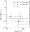 |
Fig. 12 M/L ratio and chemical ages τchem. The mass M and luminosity L for each region are taken from Beuther et al. (2018). The horizontal dashed lines correspond to average M/L ratios for HMPOs (red) and UCHII regions (blue) taken from Sridharan et al. (2002). |
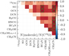 |
Fig. 13 Spearman correlation coefficient r for pairs of molecular column densities relative to N(C18O). Values higher than 0.8 are marked by a green circle. |
6.3 Correlations between chemical species
In this section, we aim to establish which molecules show a correlation via chemical links or temperature effects. We compute the Spearman correlation coefficient r for the molecular column density pair combinations relative to N(C18O). SO2, HC3N;v7 = 1, and HC3N;v7 = 2 are excluded from this analysis as there are fewer than 20 column density data points. Ideally, we would compare the correlations of relative abundance pairs relative to N(H2), but due to the issue of the missing flux, we use N(C18O), which is also detected toward all positions and is optically thin (Table B.1). Comparing the correlation between column density pairs, we ultimately face the issue that toward higher densities, the column density is also higher (as discussed in Sect. 4.2). The core and non-core positions were equally considered in the calculation of r and the results for all column density pairs are shown in Fig. 13.
In general, all pairs show a positive correlation, r > 0. High correlation coefficients (r > 0.8) are found between pairs of the following molecules: HC3N–SO, HC3N–OCS, CH3CN–SO, CH3CN–OCS, CH3CN–H2CO, CH3CN–HNCO, CH3CN–HC3N, CH3OH–CH3OH;vt = 1, CH3CN–CH3OH. The lowest correlations are found for 13CO and DCN, where there is no correlation with any species. In the case of 13CO this is most likely due to a high optical depth (Table B.1), so the column density cannot be reliably derived. The case of DCN is more puzzling, but a more detailed study of the deuteration would be required. Unfortunately, the CORE spectral setup covers only the DCN 3−2 line, so follow-up observations of deuterated species are necessary to study how deuterium chemistry behaves on such scales.
Methyl cyanide (CH3CN) shows a strong positive correlation with most other species, including S-bearing and N-bearing species. A correlation of HC3N-CH3CN can be explained by gas-phase N-chemistry in the envelope gas (Bergner et al. 2017). We find that OCS is correlated with other dense gas tracers (HC3N and CH3CN). A correlation exists between CH3OH and CH3CN even though there is no chemical link between methanol and methyl cyanide. Such a correlation has also been found toward low-mass star-forming regions (Bergner et al. 2017; Belloche et al. 2020) and toward the massive star-forming region G10.6−0.4 (Law et al. 2021). Belloche et al. (2020) argued that this is a temperature effect caused by chemically unrelated species having been evaporated from icy grain mantles by energetic processes. Additional high angular resolution observations of SiO would be helpful for studying the impact of shocks in greater detail. In the 1D physical-chemical modeling of HMSFRs with MUSCLE by Gerner et al. (2014), CH3CN, and CH3OH are co-spatial in radial abundance profiles toward the inner hot core region. Urquhart et al. (2019) find that the line integrated ratios of S- and N-bearing species are positively correlated with the dust temperature in a sample of high-mass star-forming clumps. Gratier et al. (2013) found that CH3CN is much more abundant in the photo-dissociation region (PDR) of the Horsehead nebula than the associated cold and dense core. This is consistent with the detection by Purcell et al. (2006) of 3 mm lines of CH3CN in 58 candidate hot molecular cores in a sample of 83 methanol maser-selected star-forming regions. The authors detected CH3CN in isolated methanol maser sites and found that CH3CN is more prevalent and brighter when an UCHII region is present, independently of the distance to the source. Guzmán et al. (2014) proposed that correlated abundances of CH3OH and CH3CN could be related to photochemistry, for instance, by photodesorption.
The column densities relative to N(C18O) show in general positive correlations. The N-bearing and S-bearing species seem to be chemically related by high temperature gas-phase chemistry. The strong non-correlation of DCN with any observed species requires high angular resolution follow-up observations of deuterated molecules toward these HMSFRs (e.g., N2 D+, DCO+). The correlation between CH3CN and CH3OH can be due to a mutual evaporation temperature or due to photo-desorption.
Computing the Spearman correlation coefficient r of the chemical timescales, τchem, (Table 3) with the observed column densities N (Fig. 8) and with the relative abundances N/N(C18O) (Fig. D.1) for all 22 cores, we do not find strong correlations for most of the molecular column densities and relative abundances with the chemical age. We use the mean chemical age for cores for which only a time range can be estimated. Positive correlations of the column density and relative abundance with the chemical timescale (r = 0.5−0.9) are found for SO2, HNCO, HC3N;v7 = 1, and CH3OH;vt = 1. We only detect HC3N;v7 = 2 in cores, which have a chemical age estimated to be >80 000 yr. This suggests that vibrationally and torsionally excited states of molecules are good indicators for a more evolved region, as these transitions have higher upper energy levels (Table B.1) and are only excited at a high kinetic temperature. We propose that SO2 and HNCO are also good tracers of the evolutionary stage, however, this has to be investigated using a larger statistical sample.
6.4 Comparison of physical and chemical timescales
In the following, we compare the estimated chemical timescales with commonly applied physical timescales. The free-fall timescale, τff, is the time it takes for a spherical object to fully collapse under the influence of gravity with no additional forces. It only depends on the initial density, ρ:
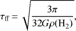 (7)
(7)
where G is the gravitational constant and ρ(H2) the initial H2 mass density.
The crossing timescale is the time it takes to cross the system once:
 (8)
(8)
with clump radius, R, and velocity dispersion, v.
A comparison between the free-fall timescales for corresponding H2 number densities of 105 cm−3, 106 cm−3, 107 cm−3, and 108 cm−3, crossing timescale (assuming R = 1 pc and v = 4 km s−1, Elmegreen 2000), and the chemical ages of the regions estimated with MUSCLE is shown in Fig. 14. A mean chemical age is used for cores for which only a time range can be determined. We then calculate the mean chemical age for regions associated with multiple cores. In these cases, the errorbars indicate the range of chemical ages. For regions associated with only one core, we assume an uncertainty of a factor of two for cores with a clear best-fit chemical age or the errorbars indicate the estimated time range for cores for which we can only determine a time range. The derived chemical ages are in agreement with an initial clump density of 105 −106 cm−3. Indeed, observations suggest that IRDCs have densities n(H2) > 105 cm−3 (e.g., Carey et al. 1998). The estimated crossing time is an upper limit, in agreement with the scenario that suggests that star formation occurs within a few crossing times (Elmegreen 2000). The agreement of the physical timescales with the chemical ages shows that even though the physical-chemical model is pseudo-time-dependent, the estimates are feasible, especially when a homogeneous data set and analysis is used.
Other forces such as magnetic fields and turbulence can slow down or prevent collapse and are important in the inital diffuse ISM (Ballesteros-Paredes et al. 2007; Burge et al. 2016). However, in the diffuse ISM, molecules, with the exception of H2, have not formed yet. Our zero point for the chemical timescales is when the density reaches 104 cm−3 and for thefree-fall timescale, we also assume densities ≥ 104 cm−3. In Beuther et al. (2018), we showed that the fragmentation scales that we observe are in agreement with thermal Jeans fragmentation, thus turbulent Jeans fragmentation is not significant here. This is fully consistent with the results found in a different sample by Palau et al. (2015). The role of magnetic fields in the CORE regions are being investigated by polarization observationswith the Submillimeter Array (SMA).
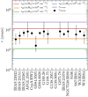 |
Fig. 14 Comparison of the free-fall timescale, τff, and crossing timescale, τcross, (colored lines), and chemical timescales, τchem, (black data points). |
7 Conclusions
In this work, we study the physical and chemical structure of 18 high-mass star-forming regions using the CORE 1 mm continuum and spectralline data. We quantify the chemical content for in total 120 positions including in total 22 cores. Combining the CORE observations with the physical-chemical model MUSCLE, we estimate the chemical timescales of the cores. Our main conclusions are summarized as follows:
- 1.
Using H2CO and CH3CN line emission, we derived temperature maps of the regions. We identify “cores” as objects having a clear radially decreasing temperature profile. We fit these radial temperature profiles and obtained an average power-law index q = 0.4 ± 0.1, excluding three outliers with q ≥ 1, which is in agreement with theoretical predictions and calculations.
- 2.
The 1.37 mm continuum visibility profiles of the cores reveal a mean density power-law index of p = 2.0 ± 0.2. Comparing these high-resolution density profiles to previous single-dish and interferometric studies, the density profiles appear to stay roughly constant between p = 1.7−2.0 from scales of 1 pc down to 1000 au. The molecular hydrogen column density N(H2) has a mean of 1.5 × 1024 cm−2 toward the 120 positions and the core mass Mcore of the 22 cores has a mean of 4.1 M⊙.
- 3.
We derived molecular column densities of 11 species by fitting their spectral lines with XCLASS. Spearman correlation coefficients are evaluated for all molecule pairs. We find high correlations between N-bearing and S-bearing species that are chemically related through high temperature gas-phase chemistry. High correlations are also found for molecules that are not chemically related (CH3CN and CH3OH), but for which the correlation results from a common evaporation temperature or photo-desorption.
- 4.
We applied the physical-chemical model MUSCLE to the observed column densities of each core to estimate the chemical age τchem. We find a spread in age from τchem ~ 20 000−100 000 yr and a mean chemical age of ~60 000 yr. Multiple cores within a region show that there can be an age gradient for largely separated cores (e.g., toward IRAS 23033 and G108.75), while close cores have a similar chemical age (e.g., toward IRAS 21078 and W3 H2O) suggesting a sequential star formation.
- 5.
A strong correlation is found between the peak column density N(H2) of the 22 cores and the M/L ratio of the region. In addition, we find a trend which posits that older cores have a lower M/L ratio. However, a larger sample is required to study the physical and chemical properties on core-scales in more detail.
- 6.
We compare the chemical age with physical timescales. We find that the chemical age is consistent with a free-fall timescale of the initial clump, at a density of 105 cm−3 and 106 cm−3, which is consistent with density values typically found toward IRDCs. The chemical ages are smaller than a crossing time of the parental clump.
- 7.
We improved the quality (both intensity and noise) of the NOEMA continuum and spectral line data by applying self-calibration. All of the standard and self-calibrated CORE data are publically available4.
The CORE data reveal a large physical and chemical diversity on scales down to ~300 au. Here, we use the molecular column densities of 120 positions toward the 18 high-mass star-forming regions to quantify the chemical content, with an emphasis on 22 cores. The case study of AFGL 2591 had already revealed complex structures around a single hot core (Gieser et al. 2019) using high-resolution interferometric observations. In a next step, we will study the spatial morphology of the molecular emission in order to evaluate the spatial correlations of the species.
Acknowledgements
The authors would like to thank the anonymous referee whose comments helped improve the clarity of this paper. This work is based on observations carried out under project number L14AB with the IRAM NOEMA Interferometer and the IRAM 30 m telescope. IRAM is supported by INSU/CNRS (France), MPG (Germany), and IGN (Spain). We thank the IRAM staff,especially R. Neri and S. Bardeau, for their help in obtaining, calibrating, and imaging the NOEMA and IRAM 30 m data. C.G., H.B., and S.S. acknowledge support from the European Research Council under the Horizon 2020 Framework Programme via the ERC Consolidator Grant CSF-648505. D.S. acknowledges support by the Deutsche Forschungsgemeinschaft through SPP 1833: “Building a Habitable Earth (SE 1962/6-1)”. R.G.-M. acknowledges support from UNAM-PAPIIT project IN104319. R.K. acknowledges financial support via the Emmy Noether Research Group on Accretion Flows and Feedback in Realistic Models of Massive Star Formation funded by the German Research Foundation (DFG) under grant no. KU 2849/3-1 and KU 2849/3-2. A.S.-M. research is partially carried out within the Collaborative Research Centre 956 (subproject A6), funded by the Deutsche Forschungsgemeinschaft (DFG) - project ID 184018 867. A.P. acknowledges financial support from CONACyT and UNAM-PAPIIT IN113119 grant, México. J.P. acknowledges support by the Programme National “Physique et Chimie du Milieu Interstellaire” (PCMI) of CNRS/INSU with INC/INP co-funded by CEA and CNES. This research made use of Astropy (http://www.astropy.org), a community-developed core Python package for Astronomy (Astropy Collaboration 2013, 2018).
Appendix A Position properties
Table A.1 summarizes the properties of all 120 positions extracted within the 18 CORE regions which were analyzed in this study. The positions are also marked in Fig. 3 showing the 1.37 mm continuum emission. Positions which show a clear temperature profile are labeled as “C” (further explained in Sect. 3.2).
Appendix B Spectral line properties
The line properties of the detected spectral lines analyzed in this study are summarized in Table B.1.
Properties of the analyzed spectral lines taken from Splatalogue (Remijan et al. 2007).
Appendix C Temperature maps
Figure C.1 shows the H2CO and CH3CN temperature maps derived with XCLASS for each region (Sect. 3.2). Each core position is marked in red and the derived outer radii from the radial temperature profiles are indicated by dashed red circles.
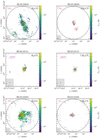 |
Fig. C.1 Temperature maps derived with XCLASS. Each panel shows in color the temperature map (left: H2CO, right: CH3CN) and in black contours the 1.37 mm continuum emission. The dashed black contours show the − 5σcont emission andthe solid black contours start at 5σcont with steps increasing by a factor of two (see Table 2 for values of σcont for each region). Each core is marked in red and the dashed red circle indicates the outer radius of the radial temperature fit (Sect. 3.2). The beam size is shown in the bottom left corner in each panel. The pink bar in the top left corner indicates a linear spatial scale of 10 000 au. The primary beam size is indicated by a black circle and for regions with no extended H2CO temperaturemap a smaller field of view is shown. |
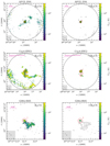 |
Fig. C.1 continued. |
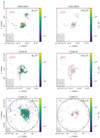 |
Fig. C.1 continued. |
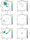 |
Fig. C.1 continued. |
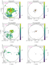 |
Fig. C.1 continued. |
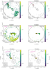 |
Fig. C.1 continued. |
Appendix D Abundance histograms
Figure D.1 shows a histogram of the abundance ratio relative to N(C18O) for each molecule complementary to the column density histograms discussed in Sect. 4.2.
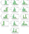 |
Fig. D.1 Abundance ratio histograms. Abundance ratio histograms of all 120 positions are shown in green (upper limits are not included). Separate abundance ratio histograms of the core and non-core positions are indicated by the dash-dotted red and dashed blue lines, respectively. |
Appendix E Column density results
Tables E.1–E.3 show the derived column densities for all molecules fitted with XCLASS (Sect. 4.2). The upper and lower errors are estimated using the MCMC error estimation algorithm in XCLASS. If the fitting results do not match our defined criteria for a good fit (further explained in Sect. 4.2), the results are considered as upper limits.
Appendix F Observed spectra
Figure F.1 shows the observed spectrum and corresponding XCLASS fit for all 120 positions analyzed in Sect. 4.2.
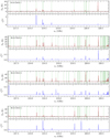 |
Fig. F.1 Broadband spectrum toward each position. Top panel: observed (black line) spectrum and XCLASS fit (red line) for all 120 analyzed positions. Fitted molecular transitions are indicated by green vertical lines. Bottom panel: optical depth profile (blue line) of all fitted transitions for all 120 analyzed positions. |
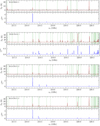 |
Fig. F.1 continued. |
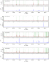 |
Fig. F.1 continued. |
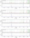 |
Fig. F.1 continued. |
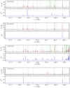 |
Fig. F.1 continued. |
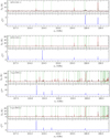 |
Fig. F.1 continued. |
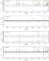 |
Fig. F.1 continued. |
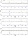 |
Fig. F.1 continued. |
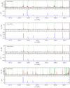 |
Fig. F.1 continued. |
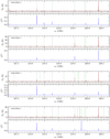 |
Fig. F.1 continued. |
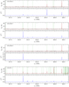 |
Fig. F.1 continued. |
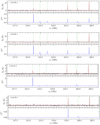 |
Fig. F.1 continued. |
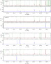 |
Fig. F.1 continued. |
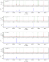 |
Fig. F.1 continued. |
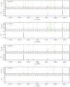 |
Fig. F.1 continued. |
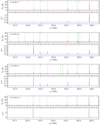 |
Fig. F.1 continued. |
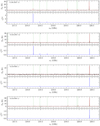 |
Fig. F.1 continued. |
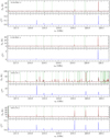 |
Fig. F.1 continued. |
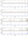 |
Fig. F.1 continued. |
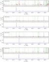 |
Fig. F.1 continued. |
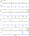 |
Fig. F.1 continued. |
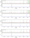 |
Fig. F.1 continued. |
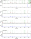 |
Fig. F.1 continued. |
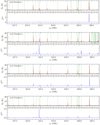 |
Fig. F.1 continued. |
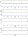 |
Fig. F.1 continued. |
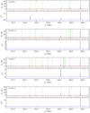 |
Fig. F.1 continued. |
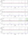 |
Fig. F.1 continued. |
 |
Fig. F.1 continued. |
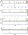 |
Fig. F.1 continued. |
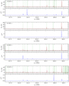 |
Fig. F.1 continued. |
Appendix G Model results
Table G.1 shows the best-fit chemical age τchem, χ2 value, and percentage of well modeled molecules for each initial condition model (HMPO, HMC, and UCHII model) for each core.
MUSCLE results for all three initial condition models.
References
- Adams, F. C. 1991, ApJ, 382, 544 [Google Scholar]
- Ahmadi, A., Beuther, H., Mottram, J. C., et al. 2018, A&A, 618, A46 [NASA ADS] [CrossRef] [EDP Sciences] [Google Scholar]
- Ahmadi, A., Kuiper, R., & Beuther, H. 2019, A&A, 632, A50 [NASA ADS] [CrossRef] [EDP Sciences] [Google Scholar]
- Allen, V., van der Tak, F. F. S., Sánchez-Monge, Á., Cesaroni, R., & Beltrán, M. T. 2017, A&A, 603, A133 [NASA ADS] [CrossRef] [EDP Sciences] [Google Scholar]
- Astropy Collaboration (Robitaille, T. P., et al.) 2013, A&A, 558, A33 [NASA ADS] [CrossRef] [EDP Sciences] [Google Scholar]
- Astropy Collaboration (Price-Whelan, A. M., et al.) 2018, AJ, 156, 123 [Google Scholar]
- Ballesteros-Paredes, J., Klessen, R. S., Mac Low, M. M., & Vazquez-Semadeni, E. 2007, in Protostars and Planets V, eds. B. Reipurth, D. Jewitt, & K. Keil (Tucson: University of Arizona Press), 63 [Google Scholar]
- Belloche, A., Müller, H. S. P., Menten, K. M., Schilke, P., & Comito, C. 2013, A&A, 559, A47 [NASA ADS] [CrossRef] [EDP Sciences] [Google Scholar]
- Belloche, A., Maury, A. J., Maret, S., et al. 2020, A&A, 635, A198 [CrossRef] [EDP Sciences] [Google Scholar]
- Beltrán, M. T., & de Wit, W. J. 2016, A&ARv, 24, 6 [Google Scholar]
- Bergner, J. B., Öberg, K. I., Garrod, R. T., & Graninger, D. M. 2017, ApJ, 841, 120 [NASA ADS] [CrossRef] [Google Scholar]
- Bertin, M., Romanzin, C., Doronin, M., et al. 2016, ApJ, 817, L12 [Google Scholar]
- Beuther, H., Schilke, P., Menten, K. M., et al. 2002, ApJ, 566, 945 [Google Scholar]
- Beuther, H., Schilke, P., Menten, K. M., et al. 2005, ApJ, 633, 535 [Google Scholar]
- Beuther, H., Churchwell, E. B., McKee, C. F., & Tan, J. C. 2007a, Protostars and Planets V (Tucson: University of Arizona Press), 165 [Google Scholar]
- Beuther, H., Leurini, S., Schilke, P., et al. 2007b, A&A, 466, 1065 [NASA ADS] [CrossRef] [EDP Sciences] [Google Scholar]
- Beuther, H., Henning, T., Linz, H., et al. 2010, A&A, 518, L78 [NASA ADS] [CrossRef] [EDP Sciences] [Google Scholar]
- Beuther, H., Mottram, J. C., Ahmadi, A., et al. 2018, A&A, 617, A100 [NASA ADS] [CrossRef] [EDP Sciences] [Google Scholar]
- Bonfand, M., Belloche, A., Menten, K. M., Garrod, R. T., & Müller, H. S. P. 2017, A&A, 604, A60 [NASA ADS] [CrossRef] [EDP Sciences] [Google Scholar]
- Bonnell, I. A. 2007, ASP Conf. Ser., 367, 303 [NASA ADS] [Google Scholar]
- Bonnell, I. A., & Bate, M. R. 2002, MNRAS, 336, 659 [Google Scholar]
- Bonnell, I. A., Bate, M. R., & Zinnecker, H. 1998, MNRAS, 298, 93 [Google Scholar]
- Bonnell, I. A., Bate, M. R., Clarke, C. J., & Pringle, J. E. 2001, MNRAS, 323, 785 [NASA ADS] [CrossRef] [Google Scholar]
- Bosco, F., Beuther, H., Ahmadi, A., et al. 2019, A&A, 629, A10 [NASA ADS] [CrossRef] [EDP Sciences] [Google Scholar]
- Bottinelli, S., Ceccarelli, C., Neri, R., et al. 2004, ApJ, 617, L69 [Google Scholar]
- Burge, C. A., Van Loo, S., Falle, S. A. E. G., & Hartquist, T. W. 2016, A&A, 596, A28 [EDP Sciences] [Google Scholar]
- Butler, M. J., & Tan, J. C. 2012, ApJ, 754, 5 [Google Scholar]
- Carey, S. J., Clark, F. O., Egan, M. P., et al. 1998, ApJ, 508, 721 [Google Scholar]
- Carter, M., Lazareff, B., Maier, D., et al. 2012, A&A, 538, A89 [NASA ADS] [CrossRef] [EDP Sciences] [Google Scholar]
- Caselli, P., Hasegawa, T. I., & Herbst, E. 1993, ApJ, 408, 548 [Google Scholar]
- Cesaroni, R., Felli, M., Testi, L., Walmsley, C. M., & Olmi, L. 1997, A&A, 325, 725 [NASA ADS] [Google Scholar]
- Cesaroni, R., Beuther, H., Ahmadi, A., et al. 2019, A&A, 627, A68 [EDP Sciences] [Google Scholar]
- Chen, Y., Li, H., & Vogelsberger, M. 2021, MNRAS, 502, 6157 [Google Scholar]
- Churchwell, E. 2002, ARA&A, 40, 27 [Google Scholar]
- Clark, B. G. 1980, A&A, 89, 377 [NASA ADS] [Google Scholar]
- Cooper, H. D. B. 2013, PhD thesis, University of Leeds, UK [Google Scholar]
- Cruz-Diaz, G. A., Martín-Doménech, R., Muñoz Caro, G. M., & Chen, Y.-J. 2016, A&A, 592, A68 [NASA ADS] [CrossRef] [EDP Sciences] [Google Scholar]
- Cuppen, H. M., Walsh, C., Lamberts, T., et al. 2017, Space Sci. Rev., 212, 1 [Google Scholar]
- Draine, B. T. 2011, Physics of the Interstellar and Intergalactic Medium (Princeton: Princeton University Press) [Google Scholar]
- Duarte-Cabral, A., Bontemps, S., Motte, F., et al. 2013, A&A, 558, A125 [NASA ADS] [CrossRef] [EDP Sciences] [Google Scholar]
- Elmegreen, B. G. 2000, ApJ, 530, 277 [Google Scholar]
- Emerson, J. P. 1988, ASI Ser. C, 241, 21 [Google Scholar]
- Endres, C. P., Schlemmer, S., Schilke, P., Stutzki, J., & Müller, H. S. P. 2016, J. Mol. Spectr., 327, 95 [NASA ADS] [CrossRef] [Google Scholar]
- Fayolle, E. C., Öberg, K. I., Garrod, R. T., van Dishoeck, E. F., & Bisschop, S. E. 2015, A&A, 576, A45 [NASA ADS] [CrossRef] [EDP Sciences] [Google Scholar]
- Feng, S., Beuther, H., Henning, T., et al. 2015, A&A, 581, A71 [NASA ADS] [CrossRef] [EDP Sciences] [Google Scholar]
- Feng, S., Beuther, H., Semenov, D., et al. 2016, A&A, 593, A46 [NASA ADS] [CrossRef] [EDP Sciences] [Google Scholar]
- Feng, S., Li, D., Caselli, P., et al. 2020, ApJ, 901, 145 [Google Scholar]
- Frau, P., Girart, J. M., Beltrán, M. T., et al. 2010, ApJ, 723, 1665 [Google Scholar]
- Gerin, M. 2013, The Molecular Universe, eds. I. W. M. Smith, C. S. Cockell, & S. Leach (Berlin, Heidelberg: Springer Berlin Heidelberg), 35 [Google Scholar]
- Gerner, T., Beuther, H., Semenov, D., et al. 2014, A&A, 563, A97 [NASA ADS] [CrossRef] [EDP Sciences] [Google Scholar]
- Gerner, T., Shirley, Y. L., Beuther, H., et al. 2015, A&A, 579, A80 [NASA ADS] [CrossRef] [EDP Sciences] [Google Scholar]
- Giannetti, A., Brand, J., Sánchez-Monge, Á., et al. 2013, A&A, 556, A16 [NASA ADS] [CrossRef] [EDP Sciences] [Google Scholar]
- Gieser, C., Semenov, D., Beuther, H., et al. 2019, A&A, 631, A142 [NASA ADS] [CrossRef] [EDP Sciences] [Google Scholar]
- Girichidis, P., Federrath, C., Banerjee, R., & Klessen, R. S. 2011, MNRAS, 413, 2741 [NASA ADS] [CrossRef] [Google Scholar]
- Gratier, P., Pety, J., Guzmán, V., et al. 2013, A&A, 557, A101 [NASA ADS] [CrossRef] [EDP Sciences] [Google Scholar]
- Guzmán, V. V., Pety, J., Gratier, P., et al. 2014, Faraday Discuss., 168, 103 [Google Scholar]
- Hartmann, L., Ballesteros-Paredes, J., & Heitsch, F. 2012, MNRAS, 420, 1457 [Google Scholar]
- Hatchell, J., Thompson, M. A., Millar, T. J., & MacDonald, G. H. 1998, A&AS, 133, 29 [NASA ADS] [CrossRef] [EDP Sciences] [Google Scholar]
- Hatchell, J., & van der Tak, F. F. S. 2003, A&A, 409, 589 [NASA ADS] [CrossRef] [EDP Sciences] [Google Scholar]
- Herbst, E., & van Dishoeck, E. F. 2009, ARA&A, 47, 427 [NASA ADS] [CrossRef] [Google Scholar]
- Hildebrand, R. H. 1983, QJRAS, 24, 267 [NASA ADS] [Google Scholar]
- Indriolo, N., Neufeld, D. A., Gerin, M., et al. 2015, ApJ, 800, 40 [NASA ADS] [CrossRef] [Google Scholar]
- Jiménez-Serra, I., Zhang, Q., Viti, S., Martín-Pintado, J., & de Wit, W. J. 2012, ApJ, 753, 34 [NASA ADS] [CrossRef] [Google Scholar]
- Johnston, K. G., Hoare, M. G., Beuther, H., et al. 2020, ApJ, 896, 35 [Google Scholar]
- Jørgensen, J. K., Belloche, A., & Garrod, R. T. 2020, ARA&A, 58, 727 [Google Scholar]
- Kauffmann, J., Bertoldi, F., Bourke, T. L., Evans, N. J., I., & Lee, C. W. 2008, A&A, 487, 993 [NASA ADS] [CrossRef] [EDP Sciences] [Google Scholar]
- Kennicutt, Robert C., J. 1998, ARA&A, 36, 189 [Google Scholar]
- Krumholz, M. R. 2015, Astrophysics and Space Science Library, Vol. 412, The Formation of Very Massive Stars, ed. J. S. Vink, 43 [Google Scholar]
- Kuiper, R., & Hosokawa, T. 2018, A&A, 616, A101 [NASA ADS] [CrossRef] [EDP Sciences] [Google Scholar]
- Kurtz, S., Churchwell, E., & Wood, D. O. S. 1994, ApJS, 91, 659 [Google Scholar]
- Larson, R. B. 1981, MNRAS, 194, 809 [Google Scholar]
- Law, C. J., Zhang, Q., Öberg, K. I., et al. 2021, ApJ, 909, 214 [Google Scholar]
- Lee, H. H., Roueff, E., Pineau des Forets, G., et al. 1998, A&A, 334, 1047 [Google Scholar]
- Looney, L. W., Mundy, L. G., & Welch, W. J. 2003, ApJ, 592, 255 [Google Scholar]
- Mangum, J. G., & Shirley, Y. L. 2015, PASP, 127, 266 [Google Scholar]
- Mangum, J. G., & Wootten, A. 1993, ApJS, 89, 123 [Google Scholar]
- Maud, L. T., Lumsden, S. L., Moore, T. J. T., et al. 2015, MNRAS, 452, 637 [Google Scholar]
- McGuire, B. A. 2018, ApJS, 239, 17 [Google Scholar]
- McKee, C. F.,& Ostriker, E. C. 2007, ARA&A, 45, 565 [Google Scholar]
- McKee, C. F.,& Tan, J. C. 2002, Nature, 416, 59 [Google Scholar]
- McKee, C. F.,& Tan, J. C. 2003, ApJ, 585, 850 [NASA ADS] [CrossRef] [MathSciNet] [Google Scholar]
- McLaughlin, D. E., & Pudritz, R. E. 1996, ApJ, 469, 194 [Google Scholar]
- McLaughlin, D. E., & Pudritz, R. E. 1997, ApJ, 476, 750 [Google Scholar]
- Mills, E. A. C., Corby, J., Clements, A. R., et al. 2018, ApJ, 869, 121 [Google Scholar]
- Molinari, S., Pezzuto, S., Cesaroni, R., et al. 2008, A&A, 481, 345 [NASA ADS] [CrossRef] [EDP Sciences] [Google Scholar]
- Molinari, S., Swinyard, B., Bally, J., et al. 2010, PASP, 122, 314 [NASA ADS] [CrossRef] [Google Scholar]
- Molinari, S., Merello, M., Elia, D., et al. 2016, ApJ, 826, L8 [Google Scholar]
- Molinari, S., Baldeschi, A., Robitaille, T. P., et al. 2019, MNRAS, 486, 4508 [NASA ADS] [CrossRef] [Google Scholar]
- Möller, T., Endres, C., & Schilke, P. 2017, A&A, 598, A7 [NASA ADS] [CrossRef] [EDP Sciences] [Google Scholar]
- Moscadelli, L., Beuther, H., Ahmadi, A., et al. 2021, A&A, 647, A114 [EDP Sciences] [Google Scholar]
- Motte, F., & André, P. 2001, A&A, 365, 440 [NASA ADS] [CrossRef] [EDP Sciences] [Google Scholar]
- Motte, F., Bontemps, S., & Louvet, F. 2018, ARA&A, 56, 41 [NASA ADS] [CrossRef] [Google Scholar]
- Mottram, J. C., Hoare, M. G., Davies, B., et al. 2011a, ApJ, 730, L33 [Google Scholar]
- Mottram, J. C., Hoare, M. G., Urquhart, J. S., et al. 2011b, A&A, 525, A149 [NASA ADS] [CrossRef] [EDP Sciences] [Google Scholar]
- Mottram, J. C., Beuther, H., Ahmadi, A., et al. 2020, A&A, 636, A118 [EDP Sciences] [Google Scholar]
- Mueller, K. E., Shirley, Y. L., Evans, Neal J., I., & Jacobson, H. R. 2002, ApJS, 143, 469 [Google Scholar]
- Müller, H. S. P., Schlöder, F., Stutzki, J., & Winnewisser, G. 2005, J. Mol. Struct., 742, 215 [Google Scholar]
- Murray, N., & Chang, P. 2012, ApJ, 746, 75 [Google Scholar]
- Obonyo, W. O., Lumsden, S. L., Hoare, M. G., et al. 2019, MNRAS, 486, 3664 [Google Scholar]
- Olguin, F. A., Hoare, M. G., Johnston, K. G., et al. 2020, MNRAS, 498, 4721 [Google Scholar]
- Osorio, M., Lizano, S., & D’Alessio, P. 1999, ApJ, 525, 808 [Google Scholar]
- Ossenkopf, V., & Henning, T. 1994, A&A, 291, 943 [NASA ADS] [Google Scholar]
- Palau, A., Estalella, R., Girart, J. M., et al. 2014, ApJ, 785, 42 [NASA ADS] [CrossRef] [Google Scholar]
- Palau, A., Ballesteros-Paredes, J., Vázquez-Semadeni, E., et al. 2015, MNRAS, 453, 3785 [NASA ADS] [CrossRef] [Google Scholar]
- Palau, A., Zhang, Q., Girart, J. M., et al. 2020, ApJ, submitted [arXiv:2010.12099] [Google Scholar]
- Pearson, T. J., & Readhead, A. C. S. 1984, ARA&A, 22, 97 [NASA ADS] [CrossRef] [Google Scholar]
- Peters, T., Mac Low, M.-M., Banerjee, R., Klessen, R. S., & Dullemond, C. P. 2010, ApJ, 719, 831 [Google Scholar]
- Pickett, H. M., Poynter, R. L., Cohen, E. A., et al. 1998, J. Quant. Spectr. Rad. Transf., 60, 883 [Google Scholar]
- Pillai, T., Wyrowski, F., Carey, S. J., & Menten, K. M. 2006, A&A, 450, 569 [NASA ADS] [CrossRef] [EDP Sciences] [Google Scholar]
- Purcell, C. R., Balasubramanyam, R., Burton, M. G., et al. 2006, MNRAS, 367, 553 [NASA ADS] [CrossRef] [Google Scholar]
- Purser, S. J. D. 2017, PhD thesis, University of Leeds, UK [Google Scholar]
- Qin, S.-L., Schilke, P., Wu, J., et al. 2015, ApJ, 803, 39 [Google Scholar]
- Radcliffe, J. F., Garrett, M. A., Beswick, R. J., et al. 2016, A&A, 587, A85 [NASA ADS] [CrossRef] [EDP Sciences] [Google Scholar]
- Rathborne, J. M., Jackson, J. M., & Simon, R. 2006, ApJ, 641, 389 [Google Scholar]
- Remijan, A. J., Markwick-Kemper, A., & ALMA Working Group on Spectral Line Frequencies. 2007, AAS Meeting Abstracts, 211, 132.11 [Google Scholar]
- Roberts, D. A., Crutcher, R. M., & Troland, T. H. 1995, ApJ, 442, 208 [Google Scholar]
- Rodgers, S. D., & Charnley, S. B. 2001, ApJ, 546, 324 [Google Scholar]
- Rodón, J. A., Beuther, H., & Schilke, P. 2012, A&A, 545, A51 [NASA ADS] [CrossRef] [EDP Sciences] [Google Scholar]
- Rosen, A. L., Offner, S. S. R., Sadavoy, S. I., et al. 2020, Space Sci. Rev., 216, 62 [Google Scholar]
- Sánchez-Monge, Á., Cesaroni, R., Beltrán, M. T., et al. 2013a, A&A, 552, L10 [NASA ADS] [CrossRef] [EDP Sciences] [Google Scholar]
- Sánchez-Monge, Á., Kurtz, S., Palau, A., et al. 2013b, ApJ, 766, 114 [Google Scholar]
- Sault, R. J., Teuben, P. J., & Wright, M. C. H. 1995, ASP Conf. Ser., 77, 433 [Google Scholar]
- Schilke, P. 2015, EAS Pub. Ser., 75, 227 [Google Scholar]
- Schilke, P., Walmsley, C. M., Pineau des Forets, G., & Flower, D. R. 1997, A&A, 321, 293 [NASA ADS] [Google Scholar]
- Schneider, N., Simon, R., Bontemps, S., Comerón, F., & Motte, F. 2007, A&A, 474, 873 [NASA ADS] [CrossRef] [EDP Sciences] [Google Scholar]
- Schöier, F. L., van der Tak, F. F. S., van Dishoeck, E. F., & Black, J. H. 2005, A&A, 432, 369 [NASA ADS] [CrossRef] [EDP Sciences] [Google Scholar]
- Semenov, D., Hersant, F., Wakelam, V., et al. 2010, A&A, 522, A42 [NASA ADS] [CrossRef] [EDP Sciences] [Google Scholar]
- Shu, F. H. 1977, ApJ, 214, 488 [Google Scholar]
- Shu, F. H., Adams, F. C., & Lizano, S. 1987, ARA&A, 25, 23 [Google Scholar]
- Smith, R. J., Longmore, S., & Bonnell, I. 2009, MNRAS, 400, 1775 [Google Scholar]
- Sridharan, T. K., Beuther, H., Schilke, P., Menten, K. M., & Wyrowski, F. 2002, ApJ, 566, 931 [Google Scholar]
- Steer, D. G., Dewdney, P. E., & Ito, M. R. 1984, A&A, 137, 159 [NASA ADS] [Google Scholar]
- Tan, J. C., Beltrán, M. T., Caselli, P., et al. 2014, Protostars and Planets VI (Tucson: University of Arizona Press), 149 [Google Scholar]
- Urquhart, J. S., König, C., Giannetti, A., et al. 2018, MNRAS, 473, 1059 [NASA ADS] [CrossRef] [Google Scholar]
- Urquhart, J. S., Figura, C., Wyrowski, F., et al. 2019, MNRAS, 484, 4444 [Google Scholar]
- van der Tak, F. F. S., van Dishoeck, E. F., Evans, Neal J., I., & Blake, G. A. 2000, ApJ, 537, 283 [Google Scholar]
- Williams, J. P., de Geus, E. J., & Blitz, L. 1994, ApJ, 428, 693 [NASA ADS] [CrossRef] [Google Scholar]
- Williams, S. J., Fuller, G. A., & Sridharan, T. K. 2004, A&A, 417, 115 [NASA ADS] [CrossRef] [EDP Sciences] [Google Scholar]
- Williams, S. J., Fuller, G. A., & Sridharan, T. K. 2005, A&A, 434, 257 [NASA ADS] [CrossRef] [EDP Sciences] [Google Scholar]
- Wilson, T. L.,& Rood, R. 1994, ARA&A, 32, 191 [Google Scholar]
- Wood, D. O. S., & Churchwell, E. 1989, ApJS, 69, 831 [Google Scholar]
- Wyrowski, F., Schilke, P., Walmsley, C. M., & Menten, K. M. 1999, ApJ, 514, L43 [Google Scholar]
- Wyrowski, F., Güsten, R., Menten, K. M., et al. 2016, A&A, 585, A149 [NASA ADS] [CrossRef] [EDP Sciences] [Google Scholar]
- Zhang, Q., Wang, Y., Pillai, T., & Rathborne, J. 2009, ApJ, 696, 268 [Google Scholar]
- Zinnecker, H., & Yorke, H. W. 2007, ARA&A, 45, 481 [NASA ADS] [CrossRef] [Google Scholar]
All Tables
Properties of the analyzed spectral lines taken from Splatalogue (Remijan et al. 2007).
All Figures
|
Fig. 1 Comparison of the GILDAS standard calibrated (left panel), CASA self-calibrated (middle panel), and GILDAS self-calibrated (right panel) W3 IRS4 continuum data. In each panel, the beam size is shown in the bottom left corner and the pink bar in the top left corner indicates a linear spatial scale of 5000 au. |
| In the text | |
|
Fig. 2 Comparison of the GILDAS standard calibration (left) and GILDAS self-calibration (right) of the W3 IRS4 broadband spectral line data zoomed in toward the position of the continuum peak, shown in the top panels. The integrated intensity of the CH3CN 123 − 113 transition is shown in color. In each panel, the beam size is shown in the bottom left corner and pink bar in the top left corner indicates a linear spatial scale of 5000 au. Bottom panel: CH3CN 123 − 113 spectrum at the position of the W3 IRS4 continuum peak of the GILDAS standard calibrated data (black) and of the GILDAS self-calibrated data (green). The dashed orange line shows the systemic velocity of the region vLSR and the dash-dotted blue lines show the lower and upper velocity limits (vLSR ± 10 km s−1) used for the integrated intensity map shown in the top panel. |
| In the text | |
|
Fig. 3 1.37 mm continuum emission. The selected positions analyzed in this paper (summarized in Table A.1) are marked and labeled in red (core positions) and blue (all remaining positions). The dashed black contours show the − 5σcont emission andthe solid black contours start at 5σcont with contoursteps increasing by a factor of 2 (e.g., −5, 5, 10, 20, 40, 80,...σcont; see Table 2 for values of σcont for eachregion). In each panel, the beam size is shown in the bottom left corner and the pink bar in the top left corner indicates a linear spatial scale of 5000 au. The field of view in each region is adjusted to only show the area with significant emission (≥ 5σcont), and for regions with wide-spread emission, the primary beam is indicated by a black circle. |
| In the text | |
|
Fig. 3 continued. |
| In the text | |
|
Fig. 3 continued. |
| In the text | |
|
Fig. 3 continued. |
| In the text | |
|
Fig. 3 continued. |
| In the text | |
|
Fig. 4 Radial temperature profiles of the 22 cores. Each panel shows the binned radial temperature profile derived from the H2CO (green) and CH3CN (blue) temperature maps shown in Fig. C.1. The data points used for the radial profile fitare shown by corresponding colored errorbars, the data points excluded from the fit are indicated by grey errorbars. The outer radius of the temperature fit is shown by the vertical purple dash-dotted line. The inner unresolved region is shown as a grey-shaded area. The linear fit and the ± 1σ uncertainty are shown by the solid and dashed red lines, respectively. |
| In the text | |
|
Fig. 4 continued. |
| In the text | |
|
Fig. 5 Histogram of the temperature power-law index q. The red line shows a Gaussian fit to the data points for q = 0.1−0.6. |
| In the text | |
|
Fig. 6 Radial visibility profiles of the 1.37 mm continuum emission of the 22 cores. The black data points show the radial profile of the averaged complex visibilities of the 1.37 mm continuum as a function of uv distance (bottom x-axis) and of the corresponding linear scale (top x-axis). The linear fit and the ±1σ uncertainties are indicated by the solid and dashed red line, respectively. |
| In the text | |
|
Fig. 6 continued. |
| In the text | |
|
Fig. 7 Histogram of the density power-law index p. The density power-law index derived with the measured values of q for each core are shown in blue. In green, the results for p calculated with a fixed temperature index (q = 0.4) for all cores are shown. The red line shows a Gaussian fit to the green histogram. |
| In the text | |
|
Fig. 8 Column density histograms. The H2 column density is derived from the 1.37 mm continuum emission and the remaining molecular column densities are derived with XCLASS. Column density histograms of all 120 positions are shown in green bars (upper limits are not included). Separate column density histograms of the core and the remaining positions are indicated by the dash-dotted red and dashed blue lines, respectively. |
| In the text | |
|
Fig. 9 Comparison of the observed and modeled column densities shown in red and blue, respectively. Upper limits are indicated byan arrow. |
| In the text | |
|
Fig. 9 continued. |
| In the text | |
|
Fig. 10 Literature comparison of the density index p at different core or clump sizes, ⟨r⟩. Studies based on interferometric observations are marked by a “ × ”, (sub)mm single-dish observations by a “•”, multi-wavelength observations by a “♦”, and mid-infrared observations by a “○”. References. M02: Mueller et al. (2002); B02: Beuther et al. (2002); H03: Hatchell & van der Tak (2003); W05: Williams et al. (2005); B07: Beuther et al. (2007b); Z09: Zhang et al. (2009); B12: Butler & Tan (2012); G13: Giannetti et al. (2013); P14: Palau et al. (2014); W16: Wyrowski et al. (2016); P20: Palau et al. (2020). |
| In the text | |
|
Fig. 11 Spearman correlation coefficient r for the derived physical and chemical core parameters listed in Table 3. Values higher than 0.8 are marked by a green circle. |
| In the text | |
|
Fig. 12 M/L ratio and chemical ages τchem. The mass M and luminosity L for each region are taken from Beuther et al. (2018). The horizontal dashed lines correspond to average M/L ratios for HMPOs (red) and UCHII regions (blue) taken from Sridharan et al. (2002). |
| In the text | |
|
Fig. 13 Spearman correlation coefficient r for pairs of molecular column densities relative to N(C18O). Values higher than 0.8 are marked by a green circle. |
| In the text | |
|
Fig. 14 Comparison of the free-fall timescale, τff, and crossing timescale, τcross, (colored lines), and chemical timescales, τchem, (black data points). |
| In the text | |
|
Fig. C.1 Temperature maps derived with XCLASS. Each panel shows in color the temperature map (left: H2CO, right: CH3CN) and in black contours the 1.37 mm continuum emission. The dashed black contours show the − 5σcont emission andthe solid black contours start at 5σcont with steps increasing by a factor of two (see Table 2 for values of σcont for each region). Each core is marked in red and the dashed red circle indicates the outer radius of the radial temperature fit (Sect. 3.2). The beam size is shown in the bottom left corner in each panel. The pink bar in the top left corner indicates a linear spatial scale of 10 000 au. The primary beam size is indicated by a black circle and for regions with no extended H2CO temperaturemap a smaller field of view is shown. |
| In the text | |
|
Fig. C.1 continued. |
| In the text | |
|
Fig. C.1 continued. |
| In the text | |
|
Fig. C.1 continued. |
| In the text | |
|
Fig. C.1 continued. |
| In the text | |
|
Fig. C.1 continued. |
| In the text | |
|
Fig. D.1 Abundance ratio histograms. Abundance ratio histograms of all 120 positions are shown in green (upper limits are not included). Separate abundance ratio histograms of the core and non-core positions are indicated by the dash-dotted red and dashed blue lines, respectively. |
| In the text | |
|
Fig. F.1 Broadband spectrum toward each position. Top panel: observed (black line) spectrum and XCLASS fit (red line) for all 120 analyzed positions. Fitted molecular transitions are indicated by green vertical lines. Bottom panel: optical depth profile (blue line) of all fitted transitions for all 120 analyzed positions. |
| In the text | |
|
Fig. F.1 continued. |
| In the text | |
|
Fig. F.1 continued. |
| In the text | |
|
Fig. F.1 continued. |
| In the text | |
|
Fig. F.1 continued. |
| In the text | |
|
Fig. F.1 continued. |
| In the text | |
|
Fig. F.1 continued. |
| In the text | |
|
Fig. F.1 continued. |
| In the text | |
|
Fig. F.1 continued. |
| In the text | |
|
Fig. F.1 continued. |
| In the text | |
|
Fig. F.1 continued. |
| In the text | |
|
Fig. F.1 continued. |
| In the text | |
|
Fig. F.1 continued. |
| In the text | |
|
Fig. F.1 continued. |
| In the text | |
|
Fig. F.1 continued. |
| In the text | |
|
Fig. F.1 continued. |
| In the text | |
|
Fig. F.1 continued. |
| In the text | |
|
Fig. F.1 continued. |
| In the text | |
|
Fig. F.1 continued. |
| In the text | |
|
Fig. F.1 continued. |
| In the text | |
|
Fig. F.1 continued. |
| In the text | |
|
Fig. F.1 continued. |
| In the text | |
|
Fig. F.1 continued. |
| In the text | |
|
Fig. F.1 continued. |
| In the text | |
|
Fig. F.1 continued. |
| In the text | |
|
Fig. F.1 continued. |
| In the text | |
|
Fig. F.1 continued. |
| In the text | |
|
Fig. F.1 continued. |
| In the text | |
|
Fig. F.1 continued. |
| In the text | |
|
Fig. F.1 continued. |
| In the text | |
Current usage metrics show cumulative count of Article Views (full-text article views including HTML views, PDF and ePub downloads, according to the available data) and Abstracts Views on Vision4Press platform.
Data correspond to usage on the plateform after 2015. The current usage metrics is available 48-96 hours after online publication and is updated daily on week days.
Initial download of the metrics may take a while.