| Issue |
A&A
Volume 626, June 2019
|
|
|---|---|---|
| Article Number | A28 | |
| Number of page(s) | 13 | |
| Section | Interstellar and circumstellar matter | |
| DOI | https://doi.org/10.1051/0004-6361/201834567 | |
| Published online | 06 June 2019 | |
Observational study of hydrocarbons in the bright photodissociation region of Messier 8★
1
Max-Planck Institute for Radioastronomy,
Auf dem Hügel,
53121
Bonn,
Germany
e-mail: This email address is being protected from spambots. You need JavaScript enabled to view it.
2
European Southern Observatory, Alonso de Córdova 3107,
Vitacura Casilla
7630355,
Santiago,
Chile
3
Instituto de Radioastronomía Milimétrica,
Avenida Divina Pastora 7,
18012
Granada,
Spain
Received:
2
November
2018
Accepted:
21
March
2019
Abstract
Aims. Hydrocarbons are ubiquitous in the interstellar medium, but their formation is still not well understood, depending on the physical environment in which they are found. Messier 8 (M8) is host to one of the brightest H II regions and photodissociation regions (PDRs) in our galaxy. With the observed C2H and c-C3H2 data toward M8, we aim at obtaining their densities and abundances and to shed some light on their formation mechanism.
Methods. Using the Atacama Pathfinder Experiment (APEX) 12 m, and the Institut de Radioastronomie Millimétrique (IRAM) 30 m telescopes, we performed a line survey toward Herschel 36 (Her 36), which is the main ionizing stellar system in M8, and an imaging survey within 1.3 × 1.3 pc around Her 36 of various transitions of C2H and c-C3H2. We used both local thermodynamic equilibrium (LTE) and non-LTE methods to determine the physical conditions of the emitting gas along with the column densities and abundances of the observed species, which we compared with (updated) gas-phase photochemical PDR models. In order to examine the role of polycyclic aromatic hydrocarbons (PAHs) in the formation of small hydrocarbons and to investigate their association with the H II region, the PDR and the molecular cloud, we compared archival Galactic Legacy Infrared Mid-Plane Survey Extraordinaire (GLIMPSE) 8 μm and the Spectral and Photometric Imaging Receiver (SPIRE) 250 μm continuum images with the C2H emission maps.
Results. We observed a total of three rotational transitions of C2H with their hyperfine structure components and four rotational transitions of c-C3H2 with ortho and para symmetries toward the H II region and the PDR of M8. Fragmentation of PAHs seems less likely to contribute to the formation of small hydrocarbons as the 8 μm emission does not follow the distribution of C2H emission, which is more associated with the molecular cloud toward the north west of Her 36. From the quantitative analysis, we obtained abundances of ~10−8 and 10−9 for C2H and c-C3H2 respectively, and volume densities of the hydrocarbon emitting gas in the range n(H2) ~5 × 10⁴–5 × 106 cm−3.
Conclusions. The observed column densities of C2H and c-C3H2 are reproduced reasonably well by our PDR models. This supports the idea that in high-UV flux PDRs, gas-phase chemistry is sufficient to explain hydrocarbon abundances.
Key words: astrochemistry / radiative transfer / ISM: abundances / HII regions / photon-dominated region / submillimeter: ISM
The reduced spectra and maps are also available at the CDS via anonymous ftp to cdsarc.u-strasbg.fr (130.79.128.5) or via http://cdsarc.u-strasbg.fr/viz-bin/qcat?J/A+A/626/A28
Member of the International Max Planck Research School (IMPRS) for Astronomy and Astrophysics at the Universities of Bonn and Cologne.
© M. Tiwari et al. 2019
 Open Access article, published by EDP Sciences, under the terms of the Creative Commons Attribution License (http://creativecommons.org/licenses/by/4.0), which permits unrestricted use, distribution, and reproduction in any medium, provided the original work is properly cited.
Open Access funding provided by Max Planck Society.
1 Introduction
Bright O and early B-type stars have strong ultraviolet (UV, hν > 13.6 eV) and far-ultraviolet (FUV, 6 eV < hν < 13.6 eV) fields that give rise to bright H II regions and photodissociation regions (PDRs). H II regions are comprised of hot ionized gas irradiated by strong UV radiations from nearby bright stars, while PDRs are at the interface of these H II regions and cold molecular clouds shielded from the illuminating star (Tielens & Hollenbach 1985). In PDRs, the heating is regulated by FUV photons which give rise to a rich hydrocarbon chemistry (e.g., Pety et al. 2005). Several studies on small hydrocarbons such as C2 H and C3 H2 have been done in diffuse clouds (Lucas & Liszt 2000; Gerin et al. 2011), massive star-forming regions (Beuther et al. 2008), planetary nebulae (Schmidt & Ziurys 2017), dark clouds (Pratap et al. 1997), and PDRs (Teyssier et al. 2004; Pety et al. 2005; Cuadrado et al. 2015; Nagy et al. 2015). These hydrocarbons play a key role in understanding the carbon chemistry taking place in both the gas phase and on grain surfaces. Several chemical pathways have been proposed for the formation of these hydrocarbons. It was found that in PDRs with low UV flux (G0 < 100 in units of the Habing 1969 radiation field, where G0 = 1 corresponds to a flux of 1.6 ×10⁻³ erg cm−2 s−1 for FUV photons) such as the Horsehead nebula, the observed abundances of hydrocarbons were found to be higher than those predicted by gas-phase chemical PDR models by an order of magnitude (Teyssier et al. 2004). This suggested that the current gas-phase chemistry does not adequately explain the observed high abundances of hydrocarbons, which led to the proposition that additional mechanisms may be responsible for their production. Le Page et al. (2003), Pety et al. (2005), and Montillaud et al. (2013) suggest that one such mechanism is the fragmentation of polycyclic aromatic hydrocarbons (PAHs) due to FUV radiation. Meanwhile in PDRs with a high UV flux (G0 ~ 104–105 in Habing units) such as the Orion bar, the observed hydrocarbon abundances can be roughly explained by gas-phase chemistry. The molecular gas gets heated to higher temperatures in high UV flux PDRs, facilitating new gas-phase formation routes, namely endothermicreactions and reactions with activation energy barriers (Cuadrado et al. 2015).
Messier 8 (M8) is among the highest UV flux (G0 ~ 105 in Habing units) (Tiwari et al. 2018) PDRs in the Milky Way. It is located in the Sagittarius-Carina arm, near our line of sight toward the Galactic center. Its distance from the sun has been estimated as ~ 1.3 kpc, a value we adopt (Damiani et al. 2004; Arias et al. 2006) (see the discussion in Tothill et al. (2008)). The open young stellar cluster NGC 6530, the H II region NGC 6523/33, and large quantities of molecular gas are associated with M8 (Tothill et al. 2008). The brightest star in the open cluster NGC 6530 is Herschel 36 (Her 36) at RA (α, J2000) = 18h03m40.s3 and Dec (δ, J2000) = − 24°22′43′′ (Woolf 1961), which has three main resolved components: a close massive binary consisting of an O9 V and a B0.5 V star, and a more distant companion O7.5 star (Arias et al. 2010 and Sanchez-Bermudez et al. 2014).
An extensive survey of M8 at submillimeter, millimeter, and far-infrared wavelengths was reported in Tiwari et al. (2018), where we explored in detail the morphology of the area around Her 36 and determined the physical conditions governing this region. Observations were performed using several receivers of the Stratospheric Observatory for Infrared Astronomy (SOFIA, Young et al. 2012), the Atacama Pathfinder EXperiment (APEX 12 m, Güsten et al. 2006), and the Institut de Radioastronomie Millimétrique (IRAM) 30 m telescopes. M8 has a face-on geometry, where the cold dense molecular cloud lies in the background with Her 36 being still very close to the dense core of the cloud from which it originated. Her 36 is fueling the H II region toward the east of it along with 9 Sagitarii (9 Sgr) (another binary with an O3.5 V and an O5-5.5V stars, Rauw et al. 2012) and a foreground veil of warm PDR gas is receding away from Her 36 toward the observer (see the sketch in Fig. 15 of Tiwari et al. 2018). Using various CO transitions from J = 1 → 0 to 16 → 15 at angular resolutions of ~ 10′′ (minimum) for CO J = 6 → 5 to 30′′ (maximum) for CO J = 2 → 1 (Tiwari et al. 2018, Table 1), we determined the average kinetic temperatures in the region ranging from 100 to 150 K and the H2 densities ranging from 104 to 106 cm−3, with an H2 column density of N(H2) ~ 3.8 × 1022 cm−2.
Several studies have addressed M8 in the X-ray, optical, and IR regimes (Stecklum et al. 1995; Damiani et al. 2004, 2017; Arias et al. 2006; Goto et al. 2006). Interestingly, Dahlstrom et al. (2013) found anomalously broad diffuse interstellar bands (DIBs) at 5780.5, 5797.1, 6196.0, and 6613.6 Å along with CH+ and CH in absorption along the line of sight to Her 36. A bright IR source, Her 36 SE (Goto et al. 2006), lying 0.25′′ south east of Her 36, is responsible for radiative excitation of CH+ and CH. The broadening of DIBs has been attributed to radiative pumping of closely spaced high-J rotational levels of small polar molecules (Dahlstrom et al. 2013; Oka et al. 2014; York et al. 2014).
With the goal of constraining the physical conditions of the gas responsible for the emission of small hydrocarbons and verifying if gas-phase chemistry alone can explain the observed abundance of small hydrocarbons in M8, we here present an inventory of small hydrocarbons found toward M8 in a comprehensive survey including both observations toward the bright stellar system Her 36 and on-the-fly (OTF) maps in a region of 4′ × 4′ (corresponding to 1.5 × 1.5 pc) around Her 36 at millimeter and submillimeter wavelengths. The organization of the paper is as follows. In Sect. 2, we summarize the observations done using the Principal Investigator (PI)230 and First Light APEX Submillimeter Heterodyne (FLASH+) receivers of the APEX1 12 m telescope and the Eight MIxer Receiver (EMIR) of the IRAM2 30 m telescope.In Sect. 3, we present the spectra and the velocity integrated maps of the observed transitions of C2 H and c-C3H2. The quantitative analysis of the data is described in Sect. 4. In Sect. 5, we discuss the results and the main conclusions of this work are summarized in Sect. 6.
2 Observations
2.1 APEX data
Observations of the N = 3 → 2 and 5 → 4 transitions of C2H and  = 63,4 → 52,3, 71,6 → 62,5, and 81,8 → 70,7 ortho and 72,6 → 61,5 and 80,8 → 71,7 para transitions of c-C3H2 were performed with the APEX 12 m submillimeter telescope during 2015 June–August (project id: M-095.F-0043-2015) and 2016 July and September (project ids: M-097.F-0030-2016 and M-098.F-0002-2016). As shown in Table 1, we used the following receivers: PI230 with a velocity resolution of 0.07 km s−1, to map the N = 3 → 2 of C2H, which is split into eight hyperfine structure (hfs) components, FLASH+ in the 460 GHz band with a velocity resolution of 0.05 km s−1, to integrate deeply on the N = 5 → 4 of C2H, (four hfs components) toward Her 36, and FLASH+ in the 345 GHz band with a velocity resolution of 0.04 km s−1, to integrate deeply on the
  = 63,4 → 52,3, 71,6 → 62,5 and 81,8 → 70,7 ortho; and 72,6 → 61,5 and 80,8 → 71,7 para transitions of c-C3H2 toward Her 36. To increase the signal-to-noise ratio (S/N), the data were later smoothed from a velocity resolution of 0.07 to 0.7 km s−1, 0.05 to 0.5 km s−1, and 0.04 to 0.4 km s−1.
The map was observed in OTF total power mode centered on RA = 18h03m40.s3 and Dec = −24°23′12′′(J2000), which corresponds to the position of Her 36. It has a size ~ 240′′ × 240′′. Deep integrations were pointed at Her 36 for ~3 min, while we integrated 0.7 s per dump for the map. An offset position relative to the center at (30′, –30′) was chosen for reference, similar to the previous observations done in Tiwari et al. (2018). The pointing accuracy (< 3′′) was maintained by pointing checks on bright sources such as Mars and R Dor with the receivers tuned to CO lines every 1–1.5 h. A forward efficiency ηf = 0.95 was used for all receivers, and the beam coupling efficiencies ηc = 0.62, 0.69 and 0.56 were used for the PI230, FLASH+340, and FLASH+460 receivers, respectively.
2.2 IRAM 30 m data
Observations of the N = 1 → 0 transition of C2H and  = 21,2 → 10,2 ortho and 20,2 → 11,1 transitions of c-C3H2 were performed with the IRAM 30 m telescope in August 2016 (project id: 017-16). Most of the 3 mm range was observed using the EMIR receivers (Carter et al. 2012) with a velocity resolution of 0.65 km s−1. Six hfs structure lines of C2H N = 1 → 0 transition were mapped and deep integration pointed observations
  = 21,2 → 10,1 ortho and 20,2 → 11,1 para transitions of c-C3H2 were performed toward Her 36.
Similarto APEX observations, the map was observed in OTF total power mode centered on Her 36 and has a size of 240′′ × 240′′. Each sub scan lasted 25 s and the integration time on the off-source reference position was 5 s. The offset position relative to the center at (30′, −30′) was similar to that used for APEX observations and the pointing accuracy (<3′′) was maintained by pointing at the bright calibrator 1757–240 every 1−1.5 h. A forward efficiency ηf = 0.95 and the beam coupling efficiency ηc = 0.69 were adopted for EMIR receivers. These values were taken from the (2015) commissioning report3.
All data reduction employed the Continuum and Line Analysis Single dish Software (CLASS) and GREnoble Graphic (GREG) softwares that are a part of the Grenoble Image and Line Data Analysis Software (GILDAS4) package andall observations are summarized in Table 1.
Observed hydrocarbons toward M8.
3 Results
3.1 Ethynyl: C2H
The ethynyl radical (C2H) was first detected in the interstellar medium (ISM) by Tucker et al. (1974). It is a linear molecule with spin rotation and hyperfine structure. The energy levels are designated as N, J, and F. The coupling between the rotational angular momentum N and the unpaired electron spin S causes spin doubling (J = N + S), while the coupling of angular momentum J and spin of the hydrogen nucleus I results in hfs (F = J + I) (Cuadrado et al. 2015). The electric dipole selection rules allow hfs splitting to occur only in specific quantum levels. We were able to identify a total of eighteen hfs components of C2H and the line parameters derived fromhfs fitting. The C2H N = 1 → 0 and 3 → 2 transitions have a single velocity component, while C2H N = 5 → 4 also have a spectrally resolved low velocity (2–8 km s−1) component, in addition to a high velocity (8–15 km s−1) component. This low velocity component is also seen in the CO, [C II] and [C I] spectra and corresponds to the warm foreground veil receding away from Her 36 toward the observer (Tiwari et al. 2018). The hfs fit parameters of the observed low and high velocity components of C2H are given in Table 2.
The hfs line fitting results for all the transitions are shown in Fig. 1. The lowest energy rotational transition N = 1 → 0 is split into six observable hfs levels that are well separated in frequency. The observed relative intensities are listed in Table A.1 and it can be seen that except for the lowest intensity lines, all match well with the expected relative intrinsic intensities as obtained from the Cologne Database for Molecular Spectroscopy5 (CDMS). Hence, the lines are optically thin with no hfs emission anomalies and are consistent with an optical depth of τ ~ 0.1. For the N = 3 → 2 rotational transition, we identified eight hfs components. Among them, some hfs features are not completely resolved and hence, some lines overlap. The J = 7/2 → 5/2, F = 4 → 3, and F = 3 → 2 overlap; and the J = 5/2 → 3/2, F = 3 → 2, and F = 2 → 1 overlap. The observed relative line intensities turn out to be different from the expected relative intensities except for the higher transitions as shown in Table A.1. This suggests optical depth effects and indeed an optical depth of τ ~ 1.74 was calculated. For the N = 5 → 4 rotationaltransition, we identified four hfs components where the lines with J = 9/2 → 7/2, F = 5 → 4, and F = 4 → 3 and the lines with J = 11/2 → 9/2, F = 6 → 5, and F = 5 → 4 overlap. The observed relative intensities match well with the expected relative intrinsic intensities and are consistent within optical depth τ ~ 0.1.
Hfs fit parameters of the observed low and high velocity components of C2 H.
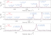 |
Fig. 1 Observed hfs components of the N = 1 → 0, 3 → 2, 5 → 4 rotational transitions of C2H toward Her 36 at RA 18h03m40s.3; Dec −24°22′43′′ (J2000). For the N = 1 → 0 transition allsix hfs are fully resolved, while for the N = 3 → 2 and 5 → 4 transitions, some hfs lines overlap with each other. The N = 5 → 4 shows an additional spectrally resolved velocity component (2–8 km s−1) compared to other transitions. Only the detected lines are indicated by their quantum numbers J and F. |
3.2 Cyclopropenylidene: c-C3H2
Cyclopropenylidene, c-C3H2, was first discovered in the ISM by Matthews & Irvine (1985) and Thaddeus et al. (1985). It is a three-membered carbon ring with C2v symmetry (see Spezzano et al. 2012, Fig. 1), with a large dipole moment of 3.4 Debye making it highly polar. It has ortho and para symmetries owing to the two out of plane hydrogen atoms, which are equidistant from the C atoms. It is an oblate asymmetric top with b-type rotational transitions where the main selection rules are ΔKa and ΔKc = ±1. The levels are ortho and para depending on the odd and even values of Ka + Kc (for a more extensive description see Cuadrado et al. 2015).
We observed two completely resolved ortho transitions  = 21,2 → 10,1 and 63,4 → 52,3, and one para transition
  = 20,2 → 11,1. In addition, we observed
  = 71,6 → 62,5 and 81,8 → 70,7 ortho, and 72,6 → 61,5 and 80,8 → 71,7 para transitions where ortho and para lines are blended. Similar to the N = 5 → 4 transition of C2 H, all observed transitions of c-C3H2 have a spectrally resolved low velocity component (centered at ~ 6 km s−1) as can be seen in Fig. 2. The line parameters are derived from a two-component Gaussian fit to the observed spectra as mentioned in Table 3.
3.3 Spatial distribution of C2H and comparison with ancillary data
Figure 3 shows velocity integrated intensity maps of the brightest transitions of C2 H N = 1 → 0, J = 3/2 → 1/2, F = 2 → 1 at 87.316 GHz with an rms noise of 0.3 K km s−1, and N = 3 → 2 J = 7/2 → 5/2, F = 4 → 3 at 262.004 GHz with an rms noise of 0.44 K km s−1. The N = 1 → 0 transition isbright toward the north west of Her 36 and peaks (in projection) deep into the molecular cloud at (Δα = –56′′, Δδ = 28′′). This position is very close to the secondary APEX Telescope Large Area Survey of the Galaxy (ATLASGAL) 870 μm dust continuum peak toward this region at (Δα = –53′′, Δδ = 23′′) (Tiwari et al. 2018, Fig. 7a), which is probing the cold molecular cloud. The N = 3 → 2 transition is brightest close to Her 36 at (Δα = 0′′, Δδ = 12′′) with the emission extending toward the north west of Her 36. The hot gas near Her 36 would be able to excite C2 H molecules torotational levels with higher upper level energies whereas the gas deep in the molecular cloud would be comparatively cooler. It is noteworthy that the extended emission, as shown in Fig. B.1, toward the north west of Her 36 is also seen in low and mid-J CO transitions and in [C I] observed toward M8 by the APEX and IRAM 30 m telescopes (Tiwari et al. 2018).
In order to investigate the relation of the dense and cold molecular cloud material to the hot ionized gas in M8, we compared our observed C2H data with observations obtained from two surveys conducted at different wavelengths. Firstly, we used the 8 μm data from the Galactic Legacy Infrared Mid-Plane Survey Extraordinaire (GLIMPSE, Benjamin et al. 2003) archive observed with Spitzer Space Telescope. The 8 μm band of the Infrared Array Camera (IRAC) used by Spitzer covers emission from PAHs which are small molecules excited by strong UV radiation. Since the IR emission from these large molecules (or small dust grains) constitutes fluorescence that results from far-UV pumping, it emerges from the surface layers of dense molecular clouds, hence PAH emission probes recent high-mass star formation (Tielens 2008). Figure 3 shows the velocity integrated intensity maps of C2 H 1 → 0 and 3 → 2 transitions in color scale overlaid with GLIMPSE 8 μm contours in black, which peak at Her 36 (Δα = 0′′, Δδ = 0′′) and at the [C II] emission peak (Δα = 30′′, Δδ = –2′′). The [C II] data was observed in May 2016 by the SOFIA telescope and have been reported in Tiwari et al. (2018). Secondly, we obtained, from the HerschelSpace Archive6 (HSA), data collected with the Spectral and Photometric Imaging Receiver (SPIRE, Griffin et al. 2010) aboard the Herschel Space Observatory (Pilbratt et al. 2010). The SPIRE data trace interstellar dust. The white contours in Fig. 3 represent the SPIRE 250 μm continuum emission, which peaks at Her 36 (Δα = 0′′, Δδ = 0′′) and is extended in the north west direction with a secondary peak coinciding with the peak of the C2 H 1 → 0 emission (Δα = –56′′, Δδ = 28′′).
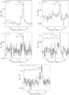 |
Fig. 2 Observations of spectrally resolved |


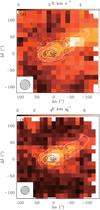 |
Fig. 3 Color maps of the velocity integrated intensity of the: upper panel: N = 1 → 0 and lower panel: 3 → 2 transitions of C2H toward Her 36, which is the central position (Δα = 0, Δδ = 0) at RA (J2000) = 18h03m40.3s and Dec (J2000) = –24°22′43′′, marked with an asterisk. Both maps are plotted using original beam sizes shown in the bottom left of each map. These maps are overlaid with contours of GLIMPSE 8 μm continuum emission in black, with a beam size of 0.6′′ and with contours of SPIRE 250 μm continuum emission in white, with a beam size of 17.9′′. For GLIMPSE 8 μm continuum emission, the contour levels are 10 to 100% in steps of 20% of the peak emission and for SPIRE 250 μm continuum emission, the contour levels are 10 to 100% in steps of 10% of the peak emission. |
c-C3H2 line parameters as calculated from two-component Gaussian fit using GILDAS.
Physical parameters calculated from rotational diagrams.
4 Analysis
Various transitions of C2H and c-C3H2 observed with the IRAM 30 m and APEX 12 m telescopes allow us to carry out a detailed analysis to determine the temperature and density of the gas responsible for the emission of hydrocarbons in M8 with several complementary methods. We started with estimating the excitation temperature and the total C2 H column density by using its OTF maps of 1 → 0 and 3 → 2 transitions in Sect. 4.1. We then calculated column densities and abundances of both C2 H and c-C3H2 from rotational diagrams in Sect. 4.2. To complete the analysis, we made use of a radiative transfer model to constrain the H2 densities in M8 in Sect. 4.3 and compared our observed results with PDR models in Sect. 4.4.
4.1 Excitation temperature and column density estimates of C2H
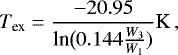
Assuming abeam filling factor of unity and optically thin emission in both the C2 H, N = 1 → 0, J = 3/2 → 1/2, F = 2 → 1 at 87.316 GHz and N = 3 → 2, J = 7/2 → 5/2, F = 4 → 3 at 262.004 GHz transitions, the excitation temperature can be estimated by
 (1)
(1)
where W1 and W3 are the velocity integrated intensities in K cm s−1 of N = 1 → 0 and 3 → 2 transitions of C2 H respectively. The resulting Tex distribution is shown in Fig. 4a, and these are only lower limits to the excitation temperature as the beam filling factor is assumed to be unity. The peak of the Tex distribution ~ 38 K ± 11 K lies in the immediate south west of Her 36 (Δα = −15′′, Δδ = −13′′delta) and Tex decreases with the distance from the star.
Assuming the environment to be in local thermodynamical equilibrium (LTE) such that all transitions have the same excitation temperature and that Tex equals the molecule’s rotation temperature, Trot, we calculated the total column density of C2H using the computed Tex and the velocity integrated intensity, W3, of N = 3 → 2 transition of C2H:
 (2)
(2)
Figure 4b shows the resulting C2H total columndensity distribution with a peak value of N(C2H) ~ (3 ± 0.26) × 1014 cm−2 at Her 36 and a secondary peak toward the north west of Her 36 in the molecular cloud similar to the secondary ATLASGAL peak. This results in an abundance of N(C2H)/N(H2) ~ 8 × 10⁻⁸, where we adopted N(H2) ~ 3.75 × 1022 cm−2 (Tiwari et al. 2018).
4.2 Rotational diagrams of C2H and c-C3H2
In Sect. 4.1, we presented the maps of excitation temperature and total column density distribution of C2 H in M8, around Her 36. However, c-C3H2 and the higher transition of C2 H were a part of point observations done by integrating deeply toward Her 36. So, we exploit the technique of rotational diagrams to perform a detailed analysis of more transitions as compared to Sect. 4.1. Also, here we plot rotational diagrams for both low and high velocity components of all observed transitions of C2 H and c-C3H2 observed toward Her 36. Assuming LTE, rotational diagrams (“Boltzmann plots”) can be used to estimate the total column densities, Ntot, of C2 H and c-C3H2 and the rotation temperatures, Trot, describing their level populations (Goldsmith & Langer 1999). In a rotational diagram, ln(Nu∕gu) is plotted versus Eup∕k. Here, ln(Nu) and gu are the column density in and the degeneracy of the upper energy level, respectively, Eup is the upper level energy, and k is the Boltzmann constant.
Given the extended emission seen in the velocity integrated intensity maps in Fig. 3, we adopted a beam filling factor of one to make rotational diagrams. Moreover, we assume the hfs lines of each rotational transition to be treated as a single component with a quantum number N. We then calculated the total velocity integrated intensity, the upper level degeneracy gu and the linestrength of different transitions as the sum of all the observed hfs components of each N + 1 → N transition. Using the weighted average with the relative strength of each line as weight, the hfs-weighted frequency ν was obtained (as in Cuadrado et al. 2015) and the Einstein coefficient A was calculated using Goldsmith & Langer (1999, Eq. (25)).
Figures 5a and b show rotational diagrams of C2 H for low (2–8 km s−1) and high (8–15 km s−1) velocity components, respectively. Firstly, under the assumption that the C2 H lines are optically thin, that is, that the optical depth correction term Cτ is unity in Goldsmith & Langer (1999, Eq. (24)), we plotted  /gu versus Eup/k in red for three transitions toward Her 36. Since the low velocity component could only be spectrally resolved for the N = 5 → 4 transition, we estimated the low velocity component’s line parameters for the other transitions assuming the same velocity and line width as that of N = 5 → 4. Subsequently, we plotted the corrected diagrams, in blue, by including the optical depth correction values according to Goldsmith & Langer (1999, Eq. (24)). The optical depth values were obtained from the hfs fit and are listed in Table 2.
Figures 5c–f show rotational diagrams of the ortho and para species of c-C3H2 for the low (2–8 km s−1) and high (8–15 km s−1) velocity components. We first assumed c-C3H2 to be optically thin and from  = 21,2 → 10,1 ortho and
  = 20,2 → 11,1 para transitions, we calculated the ortho/para ratio: ~2.2 for the low velocity component and 3.3 for the high velocity component. These ratios were used to estimate the contributions from ortho and para species to the
  = 71,6 → 62,5 and 81,8 → 70,7 ortho, and 72,6 → 61,5 and 80,8 → 71,7 para transitions, where the lines from the two species are blended together as can be seen in Fig. 2. From the obtained rotational temperatures, we estimated the column densities of C2 H and c-C3H2, which in turn were used to determine the optical depths of c-C3H2 (Goldsmith & Langer 1999, Eq. (27)). The estimated optical depth values came out to be very low, validating our assumption of optically thin c-C3H2.
The calculated rotational temperatures Trot and column densities N(X) along with their abundances N(X)/N(H2) of C2H and c-C3H2 are given in Table 4. The total column density value of C2 H at the Her 36 position calculated using the rotational diagrams is very similar to that determined in Sect. 4.1.
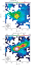 |
Fig. 4 Upper panel: excitation temperature defining the populations of N = 1 and 3 levels. Lower panel: total column density of C2H. The asterisk represents Her 36, which is the central position (Δα = 0, Δδ = 0) at RA (J2000) = 18h03m40.3s and Dec (J2000) = –24°22′43′′. The contour levels are 10–100% in steps of 10% of the corresponding peak emissions. The values of main beam brightness temperatures and that of the velocity integrated intensities for the N = 1 and 3 levels used to calculate the Tex(C2H) and N(C2H) were extracted from maps convolved to the same resolution of 30′′. |
4.3 Non-LTE calculations
In Sects. 4.1 and 4.2, we obtained the column densities and abundances of C2 H, o-C3H2 and p-C3H2 under the assumption of LTE. The derived rotational temperatures (~ 15–20 K) are much lower than the values that one might expect in the vicinity of Her 36 and temperatures derived in our previous study (Tiwari et al. 2018). This could be caused by the fact that the critical densities of the higher Eup lines of C2 H and c-C3H2 are much higher than those of the lower Eup lines of both molecules. This leads to subthermal excitation of the higher Eup lines and, consequently, to lower than LTE integrated intensities (and lower Nup/gup values). This results in a steepening of the fitted line whose slope gives Trot and an underestimation of that quantity. Therefore, the resultant rotation temperature and column densities should only be considered as guiding values. To address this issue, we employ a non-LTE analysis that delivers kinetic temperature and H2 volume densities of the gas that gives rise to the emission of C2H and C3 H2. RADEX is a non-LTE radiative transfer program (van der Tak et al. 2007), which uses the escape probability approximation for a homogeneous medium and takes into account optical depth effects. We chose a uniform sphere geometry. The collision rates used in the modeling are provided by the Leiden Molecular and Atomic Database7 (LAMDA; Schöier et al. 2005). The C2 H-H2 collision rates are calculated by multiplying a factor of 1.36 to the C2 H-He collision rates given by Spielfiedel et al. (2012), while the C3 H2-H2 collision rates are given by Chandra & Kegel (2000). We computed grids in kinetic temperatures in the range 20–250 K and H2 volume densities in the range 103 –108 cm−3 and a background temperature of 2.73 K as input parameters, and then calculated brightness temperature ratios of different transitions of C2H, o-C3H2 and p-C3H2.
We adopted the line widths from the average spectra of our data of C2 H, o-C3H2 and p-C3H2: 3, 2.5 and 2.2 km s−1, respectively for the low velocity (2–8 km s−1) component and 3.6, 3.3 and 3 km s−1, respectively for the high velocity (8–15 km s−1) component. For modeling, we used the C2H, o-C3H2, and p-C3H2 column densities as estimated from the rotational diagrams in Sect. 4.2: 7 × 10¹³, 7 × 10¹², and 4 × 1012 cm−2, respectivelyfor the low velocity component and 4 × 10¹⁴, 2 × 10¹³, and 7 × 1012 cm−2, respectively for the high velocity component. Figure 6 shows the brightness temperature ratios (in different colors) of various transitions of C2H, o-C3H2, and p-C3H2 on a log10(n(H2)) versus Tkin plot. The two different contours per color represent the RADEX modeling output values equal to the upper and lower bounds of the value obtained for each ratio from the observations with an error of 20%. For low Tkin (20–100 K), a gradient in density is seen, which then almost saturates for higher Tkin (100–250 K).
For very low temperatures, Tkin < 50 K, the H2 volume density n(H2) is as high as up to 5 × 107 cm−3. However, in our previous work we determined kinetic temperatures Tkin ~ 100–150 K in M8 (Tiwari et al. 2018, Sect. 4.3), which puts a constraint on the volume density n(H2) values. For the low velocity component shown in Fig. 6a, all hydrocarbons probe similar gas that is a part of the foreground veil, which has been found by and discussed in Tiwari et al. (2018, Sect. 5.1, Fig. 15). The foreground veil is being accelerated toward us by the strong radiation and wind of Her 36, which is a part of the cold dense molecular cloud, has H2 volume density n(H2) in a range of 5 × 10⁵–5 × 106 cm−3. For the high velocity component shown in Fig. 6b, the different ratios of C2 H probe gas of different densities. For Tkin ~ 100–150 K, C2 H (1 → 0)/(5 → 4) probe the same gas as o-C3H2 and p-C3H2 with n(H2) ~ 1 × 106 cm−3, while C2H (3 → 2)/(5 → 4) probe slightly denser gas with n(H2) ~ 5 × 106 cm−1 and C2H (1 → 0)/(3 → 2) probe lower density gas with n(H2) ~ 5 × 104 cm−3. This velocity component with an H2 volume density n(H2) in the range of 5 × 10⁴–5 × 106 cm−3, consists of the gas very close to Her 36 and also the background material toward the north east of it (Tiwari et al. 2018, Sect. 5.1).
 |
Fig. 5 Rotational diagrams of various transitions of the N = 1 → 0, 3 → 2, and 5 → 4 transitions of C2H (top row); J = 2 → 1, 6 → 5, 7 → 6, and 8 → 7 transitions of ortho c-C3H2 (top and bottom rows); and J = 2 → 1, 7 → 6, and 8 → 7 transitions of para c-C3H2 (bottom row) observed toward Her 36. For C2H, rotational diagrams are plotted with an assumption of optically thin C2H (in red) andincluding the optical depth correction factors (in blue). Fitted values of rotational temperatures are given for each molecule. The error bars were calculated from the maximum noise of the integrated intensities of individual transitions and from calibration uncertainties of 20%. |
Column densities of C2H and c-C3 H2 in M8 and the Orion Bar.
 |
Fig. 6 Results obtained from RADEX modeling for the main beam brightness temperature ratios of various transitions of C2 H and c-C3H2 toward Her 36 in a log10(n(H2)) versus Tk grid. Left and right panels: low velocity and high velocity components, respectively. The two contours per color represent the RADEX modeling output values equal to the upper and lower bounds of the value obtained for each ratio from the observationswith an error of 20%. |
 |
Fig. 7 PDR models for M8 for G0 = 104.8 and nH = 105 cm−3 (left panel) and G0 = 105 and nH = 107 cm−3 (right panel). The fractional abundances (nX∕nH) are represented by the color codes/lines patterns indicated on the plots and measured by the ordinates. The top abscissa indicates the corresponding visual extinction (AV) as seen from the ionizing front (the impinging radiation field goes from left to right of the plot). The first bottom abscissa gives the corresponding total hydrogen column density N(H). A second bottom abscissa shows the actual distance (in parsec) from the ionizing front. The vertical dashed lines demarcate the region where most of the hydrogen gas is in molecular form. |
4.4 Comparison with PDR models
In order to compare the results obtained with the LTE and non-LTE models, we use PDR models to estimate the relative abundances of the C2H and c-C3H2 species. These PDR models are based on Meijerink & Spaans (2005), which include more than 300 species in the chemical network, photo-electric heating from PAHs and small dust grains, cosmic-ray heating, and other classical heating and cooling mechanism for the thermal and chemical balance. A semi-infinite slab geometry and irradiation from one side without geometrical dilution are assumed. The PDR models do not distinguish between ortho and para molecules, but they provide the total abundance of c-C3H2 (and all other available species) self-consistently depending on the depth and visual extinction of the parallel slab. The model uses total gas density, nH = n(H) + 2n(H2), as an input parameter and the actual density of the collisional partner, molecular hydrogen n(H2), is calculated self-consistently along with the densities of other species from chemical and thermal balance equations, and is depth dependent.
We model four scenarios with two different total gas densities, nH, and two levels of strength of the impinging radiation field, G0, in Habing units. In the models we assume solar metallicity and the visual extinction is estimated using the up-to-date relation N(H) = 2.21 × 1021 cm−2 × AV found by Güver & Özel (2009).
For G0, we used the values 0.6 × 10⁵ and 1.12 × 10⁵ estimated in our previous paper (Tiwari et al. 2018, Sect. 5.2), using Tielens (2008, Eq. (9.2)) for an O star with electron density, ne, of 2000–4000 cm−3 and electron temperature, Te, of 7000–9000 K (Woodward et al. 1986; Esteban et al. 1999). We need to use quite high total gas densities, nH, of 106 and 107 cm−3 in order to reach densities of the collision partner n(H2) similar to the values found in Sect. 4.3 using RADEX. Figure 7 shows the models with the lowest density and impinging radiation field (left) and with the highest density and radiation field (right) tested.
For the highest density model (nH = 107 cm−3) we get relative abundances between 4 × 10⁻⁹ and 2 × 10⁻⁸ for C2 H and between 8 × 10⁻⁸ and 2 × 10⁻⁸ for c-C3H2, in the regionwhere H2 is more abundant than H (i.e., where H2 becomes themain collision partner, indicated with vertical dashed lines in Fig. 7). Integrating from the layer where n(H2) ≥n(H) to the far edge of the slab, we get column densities of about 2 × 1015 cm−2 for C2H and 1015 cm−2 for c-C3H2. That is, about three times and twenty five times larger than what we found from the rotational diagrams.
For the lowest density model (nH = 106 cm−3) we get relative abundances between 3 × 10⁻⁹ and 2 × 10⁻⁸ for C2 H and between 2 × 10⁻¹² and 10−8 for c-C3H2, in the regionwhere n(H2) is dominant (i.e., for AV between 1.8 and 28.6 mag, indicated by the vertical dashed lines in Fig. 7). The associated column densities are on the order of 1015 cm−2 for C2H and 4 × 1014 cm−2 for c-C3H2. That is, between factors three and ten larger than what we found from the rotational diagrams for each species.
The difference between the observed column densities and those predicted by the homogeneous PDR models can arise from the unresolved clumpiness in the gas, which is not taken into account in the calculations based on our observations. Hence, the column densities estimated from observations should be considered lower limits of the actual column densities of the species. The slab depth dependent [C2H/C3H2] abundance ratios are shown in Fig. 8 for the same models presented in Fig. 7. The C2 H molecule is about ten orders of magnitude more abundant over most of the slab’s length for all the cases studied. However, the abundance ratio decreases to just about factor two in the lower density model (nH = 106 cm−3) toward the far edge of the slab. In the higher density model (nH = 107 cm−3) instead the abundance ratio turns around as the gas cools down and C3 H2 becomes about four times more abundant than C2H. Gas temperatures reached at the far edge of the slab are about 45 K for the lower density model and about 60 K for the higher density model. Considering all the region of the slab where H2 is the most abundant species, the average gas temperatures are about 100 and 120 K for the lower and higher density PDR models, respectively. These average temperatures are similar to the values (100–150 K) we (Tiwari et al. 2018) obtained for this region of M8.
Despite not considering surface grain chemistry or mechanisms concerning PAH destruction due to UV radiation, the PDR models lead to temperatures comparable to our estimates based on the observations after using the same density values found with the non-LTE radiative transfer models. This is in favor of the argument that gas-phase chemistry is able to roughly explain the abundance of small hydrocarbons in high-UV flux PDRs.
 |
Fig. 8 Abundance ratios of [C2H∕c −C3H2] from the PDR models. The left ordinate corresponds to the abundance ratio while the right ordinate corresponds to the gas and dust temperatures. Other labels are as in Fig. 7. |
5 Discussion
5.1 Physical conditions probed by two velocity components
Two spectrally resolved velocity components are seen in the N = 5 → 4 transition of C2H (Fig. 1) and are very prominent in all transitions of c-C3H2 (Fig. 2). These two components probe regions of different temperatures and densities. As mentioned before, the low velocity component (2–8 km s−1) is a part of the gas in the foreground veil and the high velocity component (8–15 km s−1) is a part of the gas close to Her 36 and the background molecular cloud. Owing to the prominent foreground veil feature in c-C3H2, it seems to be a better probe of the warm PDR as compared to C2 H.
The rotational diagram analysis performed in Sect. 4.2, provides us with the column densities and abundances of the low and high velocity components of C2 H and c-C3H2. Lower column densities and abundances are found in the foreground veil compared to the high column densities and abundances obtained in the gas close to Her 36 and in the background molecular cloud. As described in Sect. 4.3, the non-LTE RADEX modeling provides us with H2 volume density estimates. The low velocity component (corresponding to the foreground veil) probes the high density gas in the range of 5 × 10⁵–5 × 106 cm−3, while the high velocity component (corresponding to the gas close to Her 36 and in the background molecular cloud) probes both high and low density gas in the range of 5 × 10⁴–5 × 106 cm−3.
5.2 Comparison with the Orion Bar PDR
The Orion Bar, an elongated structure in the Orion Nebula (M43), is the most-studied dense PDR (Tielens et al. 1993; Hollenbach & Tielens 1997; Walmsley et al. 2000). In particular, it is an interesting source to study small hydrocarbon chemistry in the ISM. Hogerheijde et al. (1995), Walmsley et al. (2000), and Andree-Labsch et al. (2017) described the geometry of the Orion Bar where the prominent O stars in the Trapezium illuminate the PDR, whose orientation changes from face-on to an edge-on relative to the line of sight and which appears to be located at the edge of the H II blister (Peng et al. 2012). Recent observational studies of small hydrocarbons toward this PDR have been reported by Cuadrado et al. (2015), who studied the chemistry and spatial distribution of C2 H, C4 H, c-C3H2, and c-C3H and by Nagy et al. (2015), who constrained the physical conditions of the C2 H (high transitions from N = 6 → 5 to 10 → 9) emitting gas toward the Orion Bar. Moreover, Joblin et al. (2018) reported that the formation of CH+ in PDRs like the Orion Bar opens a hot chemistry channel that leads to the formation of CO.
In Table 5, we compared the C2 H and c-C3H2 column densities toward M8 that we observe and obtain from modeling with those reported toward the Orion Bar by Cuadrado et al. (2015). We find the observed column densities to be similar in both PDRs, which was expected as we also found such similarities in the H2 volume density, in the kinetic temperature and in the CO and [C II] luminosities (Tiwari et al. 2018).
On the other hand, we found significant differences between the observed and the modeled column density of the c-C3H2 molecule. In the case of Orion it is about one order of magnitude lower than estimated from the observations. In the case of M8 the modeled column density is between one and two orders of magnitude larger than estimated from observations, which is in line with the assumption that the column densities we have determined should be considered lower limits. This suggests that there might be a significant difference between the results obtained with the Meudon PDR model used by Cuadrado et al. (2015) and our PDR model based on Meijerink & Spaans (2005). As shown in Appendix C.1, we ran our models for the Orion Bar with the same input parameters (nH = 4 × 106 cm−3 and G0 = 1.17 × 10⁴) as used by Cuadrado et al. (2015, Fig. 17, right panel). We believe that the different chemical networks used in each model that lead to the formation and destruction of the c-C3H2 molecule, are mainly responsible for their different column density predictions.
6 Conclusions
In this paper, we report APEX and IRAM 30 m observations of the N = 1 → 0, 3 → 2, and 5 → 4 transitions of C2H and of the J = 2 → 1, 6 → 5, 7 → 6, and 8 → 7 transitions of c-C3H2 toward M8. We presented the spectra of eighteen observed hfs components of C2 H and five observed transitions of ortho and para species of c-C3H2 along with the velocity integrated intensity maps of the brightest N = 1 → 0, J = 3/2 → 1/2, F = 2 → 1, and N = 3 → 2, J = 7/2 → 5/2, F = 4 → 3 transitions of C2H.
As discussed in Sect. 4.2, we inferred column densities ranging from 1012 to 1014 cm−2. C2 H is more abundant than c-C3H2 with an abundance ~ 10−8. The C3 H2 ortho/para ratio is calculated to be ~2.2 for low velocity component (corresponding to the gas in the warm foreground veil) and 3.3 for high velocity component (corresponding to the gas near Her 36 and the background molecular cloud). We also expect c-C3H2 to be a better probe than C2H for the warm PDR owing to its well-defined low velocity component feature (seen in Fig. 2).
Using non-LTE RADEX modeling (Sect. 4.3), we constrained the H2 volume densities of the hydrocarbon emitting gas to 5 × 10⁴–5 × 106 cm−3. In Sect. 4.4, we compared the observed column densities with updated PDR models and they matched the observed C2 H column densities reasonably well (by a factor of ~3) but predict higher values for c-C3H2 (by a factor of ~10–25). This discrepancy might arise from clumpy gas structure that we do not resolve with our observations. Therefore, the column densities derived from our data should be considered to be lower limits. The spatial distribution of PAH emission does not follow the C2 H emission. This is consistent with PDR models, which do not require PAH fragmentation to explain the observed column densities of C2 H and c-C3H2 in M8.
Appendix A Identified lines of hydrocarbons
Line intensities of the observed hfs transitions of C2H line taken from CDMS.
Appendix B Spatial distribution of [CI] and CO J = 6 → 5 relative to C2H N = 1 → 0
As shown in Fig. B.1, [C I] emission (in color) peaks close to Her 36 and has a bright extended emission toward the north west of it. This extended emission is also traced by CO J = 6 → 5 emission (white contours) as well as by C2H N = 1 → 0 emission (black contours).
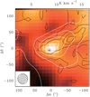 |
Fig. B.1 Color map of velocity integrated intensity of the [C I] 609 μm line overlaid with velocity integrated intensity map contours of C2H (in black) and CO J = 6 → 5 (in white). Her 36 is the central position (Δα = 0, Δδ = 0) at RA (J2000) = 18h03m40.3s and Dec (J2000) = –24°22′43′′, marked withan asterisk. For both C2H and CO J = 6 → 5, the contour levels are 10–100% in steps of 20% of the peak emission. All maps were convolved to the same resolution of 30″. |
Appendix C PDR modeling results for Orion Bar conditions
To investigate the different c-C3H2 column density values obtained by our PDR models (Meijerink & Spaans 2005) for M8 and by the Meudon code for the Orion Bar, we ran our models using the same input parameters as Cuadrado et al. (2015, Fig. 17, right panel) for their high density clump (nH = 4 × 106 cm−3 and G0 = 1.17 × 10⁴). The modeling results are presented in Fig. C.1. Clearly our models do not produce the same results as the Meudoncode (Cuadrado et al. 2015, Fig. 17, right panel). The differences in both models lie in the initial abundances of various species, in their evolution profiles, and in the temperature profiles throughout the slab (Av = 0 to 10). Differences may arise due to distinct chemical networks used in both models. The Meudon code run by Cuadrado et al. (2015) uses a total of 130 species and 2800 gas-phase reactions. The Meijerink & Spaans (2005) model, on the other hand, uses a total of 309 species and 4453 gas-phase reactions. The different initial abundances of the neutral and ionized carbon at the edge (Av = 0) of our PDR model and that of the Meudon code may also contribute to the higher column density prediction of c-C3H2. Furthermore, it is worth mentioning that the Meudon code includes the updated state-to-state reactions of vibrationally excited H2 with [C II], [O I], OH (Agúndez et al. 2010). It has also upgraded the carbon-bearing species network and used the most recent branching ratios for ion-molecule, neutral-neutral, dissociative recombination, and charge exchange reactions for carbon chains and hydrocarbon species as described in Chabot et al. (2013). These updates are missing in our PDR models. The actual impact of these exchange reactions cannot be measured until the PDR model by Meijerink & Spaans (2005) is updated.
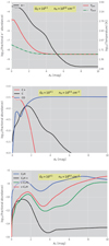 |
Fig. C.1 Results of our PDR modeling for a high density clump in the Orion Bar (nH = 4 × 106 cm−3 and G0 = 1.17 × 10⁴). In all panels, the abscissa gives visual extinction. Top panel: dependence of the electron abundance (black solid line/ left ordinate), gas temperature (red solid line/ right ordinate), and dust temperature (red line, green dash-dot/ right ordinate). Middle panel: fractional abundances of ionized and neutral carbon and CO as red, black, and blue lines, respectively. Bottom panel: fractional abundances of C2H, C2 H+, c-C3 H2, and c-C3H as ionized and neutral carbon and CO as blue, black, green, and red lines, respectively. |
References
- Agúndez, M., Cernicharo, J., & Guélin, M. 2010, ApJ, 724, L133 [NASA ADS] [CrossRef] [Google Scholar]
- Andree-Labsch, S., Ossenkopf-Okada, V., & Röllig, M. 2017, A&A, 598, A2 [NASA ADS] [CrossRef] [EDP Sciences] [Google Scholar]
- Arias, J. I., Barbá, R. H., Maíz Apellániz, J., Morrell, N. I., & Rubio, M. 2006, MNRAS, 366, 739 [NASA ADS] [CrossRef] [Google Scholar]
- Arias, J. I., Barbá, R. H., Gamen, R. C., et al. 2010, ApJ, 710, L30 [NASA ADS] [CrossRef] [Google Scholar]
- Benjamin, R. A., Churchwell, E., Babler, B. L., et al. 2003, PASP, 115, 953 [NASA ADS] [CrossRef] [Google Scholar]
- Beuther, H., Semenov, D., Henning, T., & Linz, H. 2008, ApJ, 675, L33 [NASA ADS] [CrossRef] [Google Scholar]
- Carter, M., Lazareff, B., Maier, D., et al. 2012, A&A, 538, A89 [NASA ADS] [CrossRef] [EDP Sciences] [Google Scholar]
- Chabot, M., Béroff, K., Gratier, P., Jallat, A., & Wakelam, V. 2013, ApJ, 771, 90 [NASA ADS] [CrossRef] [Google Scholar]
- Chandra, S., & Kegel, W. H. 2000, A&AS, 142, 113 [NASA ADS] [CrossRef] [EDP Sciences] [Google Scholar]
- Cuadrado, S., Goicoechea, J. R., Pilleri, P., et al. 2015, A&A, 575, A82 [NASA ADS] [CrossRef] [EDP Sciences] [Google Scholar]
- Dahlstrom, J., York, D. G., Welty, D. E., et al. 2013, ApJ, 773, 41 [NASA ADS] [CrossRef] [Google Scholar]
- Damiani, F., Flaccomio, E., Micela, G., et al. 2004, ApJ, 608, 781 [NASA ADS] [CrossRef] [Google Scholar]
- Damiani, F., Bonito, R., Prisinzano, L., et al. 2017, A&A, 604, A135 [NASA ADS] [CrossRef] [EDP Sciences] [Google Scholar]
- Esteban, C., Peimbert, M., Torres-Peimbert, S., García-Rojas, J., & Rodríguez, M. 1999, ApJS, 120, 113 [NASA ADS] [CrossRef] [Google Scholar]
- Gerin, M., Kaźmierczak, M., Jastrzebska, M., et al. 2011, A&A, 525, A116 [NASA ADS] [CrossRef] [EDP Sciences] [Google Scholar]
- Goldsmith, P. F., & Langer, W. D. 1999, ApJ, 517, 209 [NASA ADS] [CrossRef] [Google Scholar]
- Goto, M., Stecklum, B., Linz, H., et al. 2006, ApJ, 649, 299 [NASA ADS] [CrossRef] [Google Scholar]
- Griffin, M. J., Abergel, A., Abreu, A., et al. 2010, A&A, 518, L3 [Google Scholar]
- Güsten, R., Booth, R. S., Cesarsky, C., et al. 2006, Proc. SPIE, 6267, 626714 [CrossRef] [Google Scholar]
- Güver, T., & Özel, F. 2009, MNRAS, 400, 2050 [NASA ADS] [CrossRef] [Google Scholar]
- Habing, H. J. 1969, Bull. Astron. Inst. Netherlands, 20, 177 [NASA ADS] [Google Scholar]
- Hogerheijde, M. R., Jansen, D. J., & van Dishoeck, E. F. 1995, A&A, 294, 792 [NASA ADS] [Google Scholar]
- Hollenbach, D. J., & Tielens, A. G. G. M. 1997, ARA&A, 35, 179 [NASA ADS] [CrossRef] [Google Scholar]
- Joblin, C., Bron, E., Pinto, C., et al. 2018, A&A, 615, A129 [NASA ADS] [CrossRef] [EDP Sciences] [Google Scholar]
- Le Page, V., Snow, T. P., & Bierbaum, V. M. 2003, ApJ, 584, 316 [NASA ADS] [CrossRef] [Google Scholar]
- Lucas, R., & Liszt, H. S. 2000, A&A, 358, 1069 [NASA ADS] [Google Scholar]
- Matthews, H. E., & Irvine, W. M. 1985, ApJ, 298, L61 [NASA ADS] [CrossRef] [Google Scholar]
- Meijerink, R., & Spaans, M. 2005, A&A, 436, 397 [NASA ADS] [CrossRef] [EDP Sciences] [Google Scholar]
- Montillaud, J., Joblin, C., & Toublanc, D. 2013, A&A, 552, A15 [NASA ADS] [CrossRef] [EDP Sciences] [Google Scholar]
- Nagy, Z., Ossenkopf, V., Van der Tak, F. F. S., et al. 2015, A&A, 578, A124 [NASA ADS] [CrossRef] [EDP Sciences] [Google Scholar]
- Oka, T., Welty, D. E., Johnson, S., et al. 2014, ApJ, 793, 68 [NASA ADS] [CrossRef] [Google Scholar]
- Peng, T.-C., Wyrowski, F., Zapata, L. A., Güsten, R., & Menten, K. M. 2012, A&A, 538, A12 [NASA ADS] [CrossRef] [EDP Sciences] [Google Scholar]
- Pety, J., Teyssier, D., Fossé, D., et al. 2005, A&A, 435, 885 [NASA ADS] [CrossRef] [EDP Sciences] [Google Scholar]
- Pilbratt, G. L., Riedinger, J. R., Passvogel, T., et al. 2010, A&A, 518, L1 [CrossRef] [EDP Sciences] [Google Scholar]
- Pratap, P., Dickens, J. E., Snell, R. L., et al. 1997, ApJ, 486, 862 [Google Scholar]
- Rauw, G., Sana, H., Spano, M., et al. 2012, A&A, 542, A95 [NASA ADS] [CrossRef] [EDP Sciences] [Google Scholar]
- Sanchez-Bermudez, J., Alberdi, A., Schödel, R., et al. 2014, A&A, 572, L1 [NASA ADS] [CrossRef] [EDP Sciences] [Google Scholar]
- Schmidt, D. R., & Ziurys, L. M. 2017, ApJ, 850, 123 [NASA ADS] [CrossRef] [Google Scholar]
- Schöier, F. L., van der Tak, F. F. S., van Dishoeck, E. F., & Black, J. H. 2005, A&A, 432, 369 [NASA ADS] [CrossRef] [EDP Sciences] [Google Scholar]
- Spezzano, S., Tamassia, F., Thorwirth, S., et al. 2012, ApJS, 200, 1 [NASA ADS] [CrossRef] [Google Scholar]
- Spielfiedel, A., Feautrier, N., Najar, F., et al. 2012, MNRAS, 421, 1891 [NASA ADS] [CrossRef] [Google Scholar]
- Stecklum, B., Henning, T., Eckart, A., Howell, R. R., & Hoare, M. G. 1995, ApJ, 445, L153 [NASA ADS] [CrossRef] [Google Scholar]
- Teyssier, D., Fossé, D., Gerin, M., et al. 2004, A&A, 417, 135 [NASA ADS] [CrossRef] [EDP Sciences] [Google Scholar]
- Thaddeus, P., Gottlieb, C. A., Hjalmarson, A., et al. 1985, ApJ, 294, L49 [NASA ADS] [CrossRef] [Google Scholar]
- Tielens, A. G. G. M. 2008, ARA&A, 46, 289 [NASA ADS] [CrossRef] [EDP Sciences] [Google Scholar]
- Tielens, A. G. G. M., & Hollenbach, D. 1985, ApJ, 291, 722 [NASA ADS] [CrossRef] [Google Scholar]
- Tielens, A. G. G. M., Meixner, M. M., van der Werf, P. P., et al. 1993, Science, 262, 86 [NASA ADS] [CrossRef] [PubMed] [Google Scholar]
- Tiwari, M., Menten, K. M., Wyrowski, F., et al. 2018, A&A, 615, A158 [NASA ADS] [CrossRef] [EDP Sciences] [Google Scholar]
- Tothill, N. F. H., Gagné, M., Stecklum, B., & Kenworthy, M. A. 2008, Handbook of Star Forming Regions, ed. B. Reipurth (San Francisco: Astronomical Society of the Pacific), 533 [Google Scholar]
- Tucker, K. D., Kutner, M. L., & Thaddeus, P. 1974, ApJ, 193, L115 [NASA ADS] [CrossRef] [Google Scholar]
- van der Tak, F. F. S., Black, J. H., Schöier, F. L., Jansen, D. J., & van Dishoeck, E. F. 2007, A&A, 468, 627 [NASA ADS] [CrossRef] [EDP Sciences] [Google Scholar]
- Walmsley, C. M., Natta, A., Oliva, E., & Testi, L. 2000, A&A, 364, 301 [NASA ADS] [Google Scholar]
- Woodward, C. E., Pipher, J. L., Helfer, H. L., et al. 1986, AJ, 91, 870 [NASA ADS] [CrossRef] [Google Scholar]
- Woolf, N. J. 1961, PASP, 73, 206 [NASA ADS] [CrossRef] [Google Scholar]
- York, D. G., Dahlstrom, J., Welty, D. E., et al. 2014, in The Diffuse Interstellar Bands, eds. J. Cami & N. L. J. Cox, IAU Symp., 297, 89 [NASA ADS] [Google Scholar]
- Young, E. T., Becklin, E. E., Marcum, P. M., et al. 2012, ApJ, 749, L17 [NASA ADS] [CrossRef] [Google Scholar]
This publication is based on data acquired with the Atacama Pathfinder EXperiment (APEX). APEX is a collaboration between the Max-Planck-Institut für Radioastronomie, the European Southern Observatory, and the Onsala Space Observatory.
Based on observations carried out with the IRAM 30 m telescope. IRAM is supported by INSU/CNRS, the MPG (Germany), and IGN (Spain).
All Tables
c-C3H2 line parameters as calculated from two-component Gaussian fit using GILDAS.
All Figures
|
Fig. 1 Observed hfs components of the N = 1 → 0, 3 → 2, 5 → 4 rotational transitions of C2H toward Her 36 at RA 18h03m40s.3; Dec −24°22′43′′ (J2000). For the N = 1 → 0 transition allsix hfs are fully resolved, while for the N = 3 → 2 and 5 → 4 transitions, some hfs lines overlap with each other. The N = 5 → 4 shows an additional spectrally resolved velocity component (2–8 km s−1) compared to other transitions. Only the detected lines are indicated by their quantum numbers J and F. |
| In the text | |
|
Fig. 2 Observations of spectrally resolved |
| In the text | |
|
Fig. 3 Color maps of the velocity integrated intensity of the: upper panel: N = 1 → 0 and lower panel: 3 → 2 transitions of C2H toward Her 36, which is the central position (Δα = 0, Δδ = 0) at RA (J2000) = 18h03m40.3s and Dec (J2000) = –24°22′43′′, marked with an asterisk. Both maps are plotted using original beam sizes shown in the bottom left of each map. These maps are overlaid with contours of GLIMPSE 8 μm continuum emission in black, with a beam size of 0.6′′ and with contours of SPIRE 250 μm continuum emission in white, with a beam size of 17.9′′. For GLIMPSE 8 μm continuum emission, the contour levels are 10 to 100% in steps of 20% of the peak emission and for SPIRE 250 μm continuum emission, the contour levels are 10 to 100% in steps of 10% of the peak emission. |
| In the text | |
|
Fig. 4 Upper panel: excitation temperature defining the populations of N = 1 and 3 levels. Lower panel: total column density of C2H. The asterisk represents Her 36, which is the central position (Δα = 0, Δδ = 0) at RA (J2000) = 18h03m40.3s and Dec (J2000) = –24°22′43′′. The contour levels are 10–100% in steps of 10% of the corresponding peak emissions. The values of main beam brightness temperatures and that of the velocity integrated intensities for the N = 1 and 3 levels used to calculate the Tex(C2H) and N(C2H) were extracted from maps convolved to the same resolution of 30′′. |
| In the text | |
|
Fig. 5 Rotational diagrams of various transitions of the N = 1 → 0, 3 → 2, and 5 → 4 transitions of C2H (top row); J = 2 → 1, 6 → 5, 7 → 6, and 8 → 7 transitions of ortho c-C3H2 (top and bottom rows); and J = 2 → 1, 7 → 6, and 8 → 7 transitions of para c-C3H2 (bottom row) observed toward Her 36. For C2H, rotational diagrams are plotted with an assumption of optically thin C2H (in red) andincluding the optical depth correction factors (in blue). Fitted values of rotational temperatures are given for each molecule. The error bars were calculated from the maximum noise of the integrated intensities of individual transitions and from calibration uncertainties of 20%. |
| In the text | |
|
Fig. 6 Results obtained from RADEX modeling for the main beam brightness temperature ratios of various transitions of C2 H and c-C3H2 toward Her 36 in a log10(n(H2)) versus Tk grid. Left and right panels: low velocity and high velocity components, respectively. The two contours per color represent the RADEX modeling output values equal to the upper and lower bounds of the value obtained for each ratio from the observationswith an error of 20%. |
| In the text | |
|
Fig. 7 PDR models for M8 for G0 = 104.8 and nH = 105 cm−3 (left panel) and G0 = 105 and nH = 107 cm−3 (right panel). The fractional abundances (nX∕nH) are represented by the color codes/lines patterns indicated on the plots and measured by the ordinates. The top abscissa indicates the corresponding visual extinction (AV) as seen from the ionizing front (the impinging radiation field goes from left to right of the plot). The first bottom abscissa gives the corresponding total hydrogen column density N(H). A second bottom abscissa shows the actual distance (in parsec) from the ionizing front. The vertical dashed lines demarcate the region where most of the hydrogen gas is in molecular form. |
| In the text | |
|
Fig. 8 Abundance ratios of [C2H∕c −C3H2] from the PDR models. The left ordinate corresponds to the abundance ratio while the right ordinate corresponds to the gas and dust temperatures. Other labels are as in Fig. 7. |
| In the text | |
|
Fig. B.1 Color map of velocity integrated intensity of the [C I] 609 μm line overlaid with velocity integrated intensity map contours of C2H (in black) and CO J = 6 → 5 (in white). Her 36 is the central position (Δα = 0, Δδ = 0) at RA (J2000) = 18h03m40.3s and Dec (J2000) = –24°22′43′′, marked withan asterisk. For both C2H and CO J = 6 → 5, the contour levels are 10–100% in steps of 20% of the peak emission. All maps were convolved to the same resolution of 30″. |
| In the text | |
|
Fig. C.1 Results of our PDR modeling for a high density clump in the Orion Bar (nH = 4 × 106 cm−3 and G0 = 1.17 × 10⁴). In all panels, the abscissa gives visual extinction. Top panel: dependence of the electron abundance (black solid line/ left ordinate), gas temperature (red solid line/ right ordinate), and dust temperature (red line, green dash-dot/ right ordinate). Middle panel: fractional abundances of ionized and neutral carbon and CO as red, black, and blue lines, respectively. Bottom panel: fractional abundances of C2H, C2 H+, c-C3 H2, and c-C3H as ionized and neutral carbon and CO as blue, black, green, and red lines, respectively. |
| In the text | |
Current usage metrics show cumulative count of Article Views (full-text article views including HTML views, PDF and ePub downloads, according to the available data) and Abstracts Views on Vision4Press platform.
Data correspond to usage on the plateform after 2015. The current usage metrics is available 48-96 hours after online publication and is updated daily on week days.
Initial download of the metrics may take a while.