| Issue |
A&A
Volume 621, January 2019
|
|
|---|---|---|
| Article Number | A27 | |
| Number of page(s) | 70 | |
| Section | Extragalactic astronomy | |
| DOI | https://doi.org/10.1051/0004-6361/201732485 | |
| Published online | 03 January 2019 | |
Massive galaxies on the road to quenching: ALMA observations of powerful high redshift radio galaxies
1
European Southern Observatory, Karl-Schwarzchild-Str. 2, 85748
Garching, Germany
2
Sorbonne Université, CNRS UMR 7095, Institut d’Astrophysique de Paris, 98bis bvd Arago, 75014
Paris, France
e-mail: theresa.falkendal@iap.fr
3
International Center for Radio Astronomy Research, Curtin University, Perth
WA, 6845
Australia
4
National Radio Astronomy Observatory, 520 Edgemont Rd, Charlottesville, VA, 22903
USA
5
Department of Astronomy, The University of Tokyo, 7-3-1 Hongo, Bunkyo-ku, Tokyo, 133-0033
Japan
6
National Observatory of Japan, 2-21-1 Osawa, Mitaka, Tokyo, 181-0015
Japan
7
Institut d’Astrophysique Spatiale, CNRS, Université Paris Sud, 91405
Orsay, France
8
Aix-Marseille Univ., CNRS, LAM, Laboratoire d’Astrophysique de Marseille, 13013
Marseille, France
9
Centre for Extragalactic Astronomy, Department of Physics, Durham University, South Road, Durham, DH1 3LE
UK
10
Department of Physics and Astronomy, Johns Hopkins University, Bloomberg center, 3400 N. Charles St, Baltimore, MD, 21218
USA
Received:
18
December
2017
Accepted:
10
July
2018
We present 0.″3 (band 6) and 1.″5 (band 3) ALMA observations of the (sub)millimeter dust continuum emission for 25 radio galaxies at 1 < z < 5.2. Our survey reaches a rms flux density of ∼50 μJy in band 6 (200–250 GHz) and ∼20 μJy in band 3 (100–130 GHz). This is an order of magnitude deeper than single-dish 850 μm observations, and reaches fluxes where synchrotron and thermal dust emission are expected to be of the same order of magnitude. Combining our sensitive ALMA observations with low-resolution radio data from ATCA, higher resolution VLA data, and infrared photometry from Herschel and Spitzer, we have disentangled the synchrotron and thermal dust emission. We determine the star-formation rates and AGN infrared luminosities using our newly developed Multi-resolution and multi-object/origin spectral energy distribution fitting code (MR-MOOSE). We find that synchrotron emission contributes substantially at λ ∼ 1 mm. Through our sensitive flux limits and accounting for a contribution from synchrotron emission in the mm, we revise downward the median star-formation rate by a factor of seven compared to previous estimates based solely on Herschel and Spitzer data. The hosts of these radio-loud AGN appear predominantly below the main sequence of star-forming galaxies, indicating that the star formation in many of the host galaxies has been quenched. Future growth of the host galaxies without substantial black hole mass growth will be needed to bring these objects on the local relation between the supermassive black holes and their host galaxies. Given the mismatch in the timescales of any star formation that took place in the host galaxies and lifetime of the AGN, we hypothesize that a key role is played by star formation in depleting the gas before the action of the powerful radio jets quickly drives out the remaining gas. This positive feedback loop of efficient star formation rapidly consuming the gas coupled to the action of the radio jets in removing the residual gas is how massive galaxies are rapidly quenched.
Key words: galaxies: active / galaxies: high-redshift / galaxies: jets / galaxies: ISM / galaxies: evolution / galaxies: star formation
© ESO 2019
 Open Access article, published by EDP Sciences, under the terms of the Creative Commons Attribution License (http://creativecommons.org/licenses/by/4.0), which permits unrestricted use, distribution, and reproduction in any medium, provided the original work is properly cited.
1. Introduction
The connection between active galactic nuclei (AGN), their host galaxies and environments has been one of the central questions in extra-galactic astrophysics for over 30 years (Balick & Heckman 1982). This contemporary debate centers around two predominant issues concerning the influence of AGN on their environment: Is their influence “positive” or “negative”, meaning do they either increase or decrease the star-formation efficiency of their hosts? How do super-massive black holes (SMBHs) regulate their own growth? These two questions are intertwined. When the SMBH is active, it may well regulate its own growth while also enhancing or inhibiting the stellar or baryonic mass growth of its host. The empirical, approximately linear relationship between the mass of SMBH and both galaxy bulge mass and the velocity dispersion (e.g. Magorrian et al. 1998; Gebhardt et al. 2000; Ferrarese & Merritt 2000; Häring & Rix 2004), suggests that the growth of these two components is concomitant along the observed relationship. However, it is not clear if this relation is causal or if it simply reveals a connection between galaxy-galaxy mergers and that the growth of galaxy components are limited asymptotically (central limit theorem, e.g., Peng 2007; Jahnke & Macciò 2011).
SMBHs and host galaxies share several properties. Both SMBHs and galaxies have exponential cut-offs at the high mass end of their co-moving space densities (e.g., Shankar et al. 2009; Ilbert et al. 2013; Kelly & Shen 2013). The population of both SMBHs and galaxies also exhibit mass downsizing whereby the oldest, in the case of galaxies, and the most massive of SMBHs grew early and rapidly (e.g., Thomas et al. 2005, 2010; Merloni & Heinz 2008). However, there is a mismatch in both the shape and co-moving number density between galaxies and dark matter halos, especially at the low and high mass ends of these functions (Benson et al. 2003). Because powerful AGN can have a mechanical and radiative energy output similar to or exceeding that of the binding energy of a massive galaxy and dark matter halo, AGN are thought to play a key role in regulating the baryonic growth of galaxies. Both observations and simulations have suggested that there may be a positive trend between the mean black hole accretion rate and star-formation rate (SFR; e.g., Delvecchio et al. 2015; McAlpine et al. 2017), while the mean SFR as a function of black hole accretion rate shows no correlation for low luminosity sources (e.g., Stanley et al. 2015; McAlpine et al. 2017). One should be cautious when interpreting both theoretical and observational results in the definition of what exactly AGN feedback is and how AGN affect their host galaxies to explain the properties of an ensemble of galaxies (Scholtz et al. 2018). The strength and nature of AGN feedback – the cycle whereby the SMBH regulates both its own growth and that of its host – depends on galaxy mass and morphology. For example, the most massive elliptical galaxies are generally metal-rich and old, while less massive lenticular galaxies, which make up the bulk of the early-type galaxy population, have star formation histories that lasts significantly longer (Thomas et al. 2005, 2010; Emsellem et al. 2011; Krajnović et al. 2011). Clearly, if AGN feedback plays a crucial role in shaping the ensemble of galaxies, its impact on massive dispersion dominated galaxies must result in somewhat different characteristics in these galaxies compared to rotationally-dominated and predominately less massive lenticular galaxies.
To gain a deeper understanding about how the growth of host galaxy and the SMBH are intertwined, it is important to study the characteristics of the star formation occurring in the host galaxies of actively fueled black holes. Within this context, powerful radio galaxies generally, and high-redshift radio galaxies (HzRGs) in particular, are important test beds of our ideas on the physics underlying AGN feedback. At almost all redshifts, powerful radio-loud AGN are hosted by galaxies that are among the most massive (Bithell & Rees 1990; Lehnert et al. 1992; van Breugel et al. 1998; Rocca-Volmerange et al. 2004; Best et al. 2005). Since we know that at low redshift the star formation history of many of these galaxies was brief, but intense (e.g., Thomas et al. 2005; Tadhunter et al. 2011), and they lie at the exponential high mass tail of the stellar mass distribution (e.g., Seymour et al. 2007; Ilbert et al. 2013), if AGN play an important role in shaping massive galaxies, it is in these galaxies that this must be most evident. Most importantly, HzRGs are luminous sources not only in the radio, but also throughout the mid-infrared (MIR) and sub-mm continuum. This generally implies that they have high rates of star-formation (Archibald et al. 2001; Reuland et al. 2003), and a rapid accretion onto the SMBH. Due to the fact that the broad line region and rest-frame ultraviolet-optical continuum emission from their accretion disks is obscured, we can observe their stellar emission (Seymour et al. 2007; De Breuck et al. 2010). All of these arguments make HzRGs important targets for understanding the complex relationship between AGN and massive galaxies.
The substantial mechanical and radiative AGN luminosity and apparently significant star-formation rates of HzRGs leads to a quandary. If AGN feedback effectively suppresses black hole and galaxy growth, why do the host galaxies of AGN grow so rapidly (mass doubling times of ∼0.1–1 Gyr, Drouart et al. 2014)? This is the “coordination problem”, the apparent contradiction which is a paradoxical situation where the strongest phase of energy and momentum injection into the interstellar medium of the host galaxy by the AGN is not co-concomitant with strong suppression of star formation (see e.g., Drouart et al. 2014, 2016). Models predict an offset between the fueling of the AGN and the suppression of star formation because the timescales for fueling the AGN is substantially shorter than the star-formation timescale within the host. Could the impact of AGN feedback be to increase the star formation efficiency in galaxies (i.e., “positive feedback”; Silk 2013; Kalfountzou et al. 2017)?
The bulk of the bolometric output of HzRGs is emitted in the infrared (IR; e.g., Miley & De Breuck 2008). Both AGN and star-formation (SF, dust heated by stars) contribute energy to the dust continuum spectral energy distribution; the AGN heats the dust to warm temperatures (T ≳ 60 K) emitting in the MIR, while the SF generally heats the dust to lower temperatures (T ≲ 60 K) and emits mainly in the far-infrared (FIR). The Herschel space telescope provided an opportunity to cover both sides of the peak of thermal emission allowing us to disentangle the dust components heated by AGN and SF. In our Herschel radio galaxy evolution (HeRGÉ) project, we constrained spectral energy distributions (SEDs) for a sample of 70 radio galaxies at 1 < z < 5.2 (Drouart et al. 2014). While this led to substantially improved estimates of the SFR, one limitation of Herschel data are their low spatial resolution (e.g., 36″ at 500 μm). As shown by several arcsecond resolution follow-up observations, the dust continuum emission often splits into several components, which are not necessarily coincident with the AGN host galaxy (De Breuck et al. 2005; Ivison et al. 2008, 2012; Nesvadba et al. 2009; Emonts et al. 2014; Gullberg et al. 2016). Sub-arcsecond resolution imaging is therefore essential to separate the star formation occurring in the AGN host galaxies from that occurring in the nearby companion galaxies. We have therefore started a large systematic follow-up program of our HeRGÉ sample with the Atacama Large Millimeter Array (ALMA).
As HzRGs are, by selection, the brightest radio sources at each redshift, synchrotron radiation may make a substantial contribution at (sub)mm wavelengths. This was already discussed by Archibald et al. (2001), who concluded the 850 μm fluxes of three sources in their sample of 47 may be dominated by synchrotron emission. However, to make such an assessment, one has to assume that the sub-mm fluxes are a straight power-law extrapolation of the radio SED. While one may expect the spectra to steepen at high frequencies due to aging of high energy electrons, there are also suggestions that the SEDs in at least some HzRGs remain a power law with a constant exponent even at the highest observed radio and/or mm frequencies (Klamer et al. 2006).
The high sensitivity of ALMA also allows us to reach flux density levels more than an order-of-magnitude fainter than previous single-dish observations with LABOCA or SCUBA. Reaching such depths implies that we may reach flux density levels of the extrapolated synchrotron emission in most of the sources in our sample. It is therefore essential to disentangle the thermal dust and synchrotron components. To achieve this, we adopt two strategies: (1) multi-frequency photometry covering the range 10 < νobs < 200 GHz, and (2) spatially resolving the radio core and lobes. For this first strategy, we combine our ALMA data with 7 mm and 3 mm observations from the Australia Telescope Compact Array (ATCA; Emonts et al. 2014). For the second strategy, we use the available radio maps from the Very Large Array (VLA; Carilli et al. 1997; Pentericci et al. 2000; De Breuck et al. 2010), which have similar spatial resolution as our ALMA data. A more detailed study of the physics of the high-frequency synchrotron emission is deferred to a forthcoming paper. For now, we simply consider the possibility that synchrotron component will impact our (sub)mm observations and our estimates of the SFRs of the AGN host galaxy.
The three main SED components, synchrotron emission, AGN and SF heated thermal dust emission constitute the SEDs of HzRGs. Because each component potentially makes a significant contribution to the over all SED, it requires an analysis of photometry covering an order-of-magnitude range in spatial scales – sub arcsecond to 10s of arc seconds. To this end, we developed the Multi-resolution and multi-object/origin spectral energy distribution fitting procedure MR-MOOSE (Drouart & Falkendal 2018). This versatile code allows us to isolate the SF heated dust emission  from the two spectrally adjacent components – the AGN heated dust component at higher frequencies and the synchrotron emission at lower frequencies. We revise the
  downwards by a factor of many compared to previous Herschel determinations.
This paper is structured as follows: after introducing the sample and observations in Sect. 2, we briefly describe our fitting code in Sect. 3. The overall results are described in Sect. 4, with detailed descriptions of each individual source given in the appendix. We discuss the implications of our results in Sect. 5, and summarize our conclusions in Sect. 6.
2. Observations and data reduction
2.1. Sample
Our sample consists of 25 HzRGs over the redshift range 1 < z < 5.2. This is a subsample of the parent HeRGÉ sample of 70 HzRG a project dedicated to observed HzRGs with Herschel (described in detail in Seymour et al. 2007; De Breuck et al. 2010). To summarize, the parent samples sources were selected to have luminosities at rest-frame 3 GHz greater than 1026 W Hz−1 and have ultra-steep radio spectra (α = −1.0; Sν ∝ να, at νobs ∼1.4 GHz). The parent sample has complete 12-band 3.6–850 μm photometry from Spitzer, Herschel SCUBA/LABOCA (De Breuck et al. 2010; Drouart et al. 2014). The subsample of 25 sources observed with ALMA were chosen to be easily observable by ALMA, i.e., the southern part of the parent sample and were grouped in such a way that multiple sources share a phase calibrator to minimize the overheads to the extent possible.
2.2. ALMA observations
ALMA Cycle 2 band 6 (and band 4 for source TN J2007−1316) observations were carried out from June 2014 to September 2015 (Table 1). We used four 1.875 GHz spectral windows, tuned to cover molecular lines at the specific redshift of each source (McMullin et al. 2007). The data was calibrated in CASA (Common Astronomy Software Application) with the supplied calibration script (with exception of MRC 2224−273, for which the provided script was changed to correctly compensate for different averaging factor in one of the spectral windows). Since a significant fraction of our sources have a low signal-to-noise ratio, we decided to optimize the sensitivity by using natural weighting to construct images. For all sources, except TN J2007−1316, atmospheric absorption noise was present in observations, therefore we excluded the affected channels from the final images. The settings used in our data reduction were: cell size of 0.06 arcsec (roughly five times smaller than the beam size), barycentric reference frame (BARY), and the mode “mfs” (multi-frequency synthesis emulation). For the brightest source MRC 0114−211, a phase self-calibration was done which decreased the RMS noise in the final image from 87 μJy to 59 μJy.
Details about the ALMA observations.
The ALMA Cycle 3 band 3 (and band 4 for source MRC 0943−242) observations were conducted from March 2016 to September 2016 (Table 1). We used four 1.875 GHz spectral windows tuned to include the [CI]3P1−3P0 line in one of the side bands. Just as for the Cycle 2 observations the data were calibrated in CASA with the calibration scripts provided by the observatory and the continuum maps were produced in the same way, i.e., natural weighting, cell size of 0.28 arcsec, BARY and mode mfs, to be consistent over the whole sample.
For the source, 4C 23.56, we use the ALMA band 3 and 6 continuum data presented in Lee et al. (2017). Please see Lee et al. (2017) for details of the observations and data reduction.
2.3. ATCA 7 mm and 3 mm data
The ATCA observations of 7 mm continuum in some of the sources were conducted over 2009−2013. These continuum data were part of a survey to search for cold molecular CO(1–0) gas in high redshift radio galaxies (Emonts et al. 2014). The data were obtained using the compact hybrid H75, H168 and H214 array configurations, with maximum baselines of 89, 192 and 247 m, respectively. This resulted in synthesized beams ranging from roughly 6−13 arcsec. We used the Compact Array Broadband Backend (CABB; Wilson et al. 2011) with an effective 2 GHz bandpass and 1 MHz channels, centered on the redshifted CO(1–0) line (32−48 GHz; Emonts et al. 2014). The data were calibrated using the software package, MIRIAD (Sault et al. 1995). The observing and data reduction strategy, as well as the basic data products, were previously described in Emonts et al. (2011a, 2014). For MRC 0943−242, we also used the ATCA 3 mm ATCA/CABB system on March 21 2012 in the H168 array configurations and on September 30 and Oct 1 2012 in the H214 array configuration to obtain an upper limit of the radio continuum at 88.2 GHz. This frequency corresponds to the redshifted CO(3–2) line, which was not detected in our observations. We used PKS 1253−055 (March) and PKS 0537−441 (Sept/Oct) for bandpass calibration, PKS 0919−260 for frequency gain calibration, and Mars (March) and Uranus (Sept/Oct) to set the absolute flux levels. The total on-source integration time was 5.1 hrs. We used a standard observing and data reduction strategy to calibrate these 3 mm data, matching the strategy of the 7 mm data. The resulting synthesized beam of these 3 mm data is 2.4″ × 1.9″ (PA 82°) after robust +1 weighting (Briggs 1995). The rms noise level of these 3 mm data are 0.3 mJy beam−1.
3. Mr-Moose
MR-MOOSE is a new SED fitting code, developed with the goal of being able to handle multi-resolution photometric data that have multiple spatially-resolved detections in the same photometric band. The specific motivation for developing this new code is to be able to make full use of the information contained in deep and high resolution ALMA data. When combining ALMA and radio interferometric (such as JVLA and ATCA) data with previous low resolution data (such as Herschel or Spitzer) where the beam is too large to resolve individual components, one needs a SED fitting tool able to handle multiple components in order to make full use of the interferometric data which often contain multiple resolved components. MR-MOOSE1 is open source and the current version operates in MIR to radio wavelengths (Drouart & Falkendal 2018). The code relies on simple analytic models to describe the underlying physical processes. It is up to the user to define which data point should be fitted to which analytic models. Each photometric data point can be associated to any number of models and combinations of different models. It therefore only requires the user to make educated guesses about the underlying physical processes responsible for the observed flux and does not require the user to select only one possible choice. The code fits simultaneously all pre-selected analytic models and uses Bayesian statistics to find the most likely solution given the set of observed fluxes. The Bayesian, Monte Carlo Markov chain (MCMC) approach provides marginalized posterior probability density functions (PDF) for each of the free parameters.
In this paper, we model the MIR through radio spectral energy distributions with three components: a component representing dust heated by an AGN which we model as a power law with a slope, γ, and an exponential cut-off at νcut Eq. (1); a component representing dust heated by the young stellar population of the host galaxy or companion which we model as a modified blackbody Eq. (2); and a component representing synchrotron emission which we modeled as a simple power law with constant slope, α, with no cut-off at high frequencies Eq. (3). Table 2 summarizes the allowed range and the number of free parameters in the three different models.
Free parameters in our models and their allowed ranges.
 |
Fig. 1. Best fit of the SED of 4C 23.56 when assuming that the AGN is solely responsible for the mid-infrared emission and allowing λcut to be an additional free parameter. The black solid line shows the best fit with |
3.1. Analytic models
In this paper, simple analytic models are used to fit each component of the SED, instead of, using a (perhaps more realistic) physical models because of the limited number of data points available. As is often the case for high-redshift studies, we are limited to broad band photometric data. So even though this sample of galaxies has been observed with Herschel, Spitzer, LABOCA, and now ALMA, we are still limited to ∼10 data points in the infrared. To properly constrain more complex models, more data points are needed. We therefore rely on less complicated, but empirically justifiable models, to fit the data in a statistically robust way and to prevent the temptation to over-interpret the physical processes underpinnings of our results (e.g., the characteristics of the AGN torus which may be responsible for reprocessing the emission from the accretion disk).
3.1.1. AGN model
The IR-luminosity of the source is modeled following the study of Casey (2012). The mid- and far-infrared SEDs are fitted with a combination of a simple power law with a low frequency exponential cut-off and a single temperature modified blackbody. These two simple models represents the dust heated by both the AGN and star-formation in the galaxy respectively. However, in this paper, the two models to describe the AGN and SF component are de-coupled and normalized individually to fit the photometry. The functional form of the dust heated by the AGN is,
where νcut is the rest-frame frequency of the exponential cut-off of the power law. The shape at longer wavelengths of the heated dust by AGN is not well constrained because cold dust emission often completely dominates at longer wavelengths making it very difficult to determine the actual shape of the AGN emission. Therefore, we use a simple exponential with a fixed rest-frame cut-off wavelength/frequency at λcut = 33 μm or νcut = 9.085 THz. This value was determined by letting λcut be a free parameter for one galaxy and finding the best fit value. The mid-infrared emission of 4C 23.56 appears to predominately due to warm dust emission from its AGN and the far-infrared emission is very faint suggesting that it has a very low star formation rate. Within our sample, this makes 4C 23.56 the most obviously suitable choice for determining λcut for this sample of HzRGs. Fig. 1 shows the best fit with λcut as a free parameter. The chosen model for the warm dust used in this paper has also been adopted in other studies. For example, Younger et al. (2009) found good agreement when fitting the IR emission of luminous high-redshift galaxies with a modified blackbody paired with a power law component at short wavelengths.
3.1.2. Star-formation model
The far-infrared emission from dust heated by star-formation is fitted by a simple single temperature modified blackbody (i.e., a “graybody”),
where Bν(ν, T) is a blackbody (BB) distribution, ν0 is the critical frequency where the source becomes optically thin (assumed to be fixed at ν0 = 1.5 THz; Conley et al. 2011) and β is the emissivity, which we fixed at β = 2.5. The value of the emissivity depends on the characteristics of the dust grain size, composition, distribution and how efficiently the grains re-emit the absorbed energy. It is common to assume a β in the range 1–2 (Hildebrand 1983) but values of up to 2.5 at sub-mm wavelengths have been found in the integrated SEDs of galaxies (Galametz et al. 2012; Cortese et al. 2012). A value of β = 2.5 has been adopted in this paper. This is justified because sources with both LABOCA and ALMA detections in the submm have SEDs that are better fit with β = 2.5 compared to models with β ∼ 1.5 − 2. Whether or not this is physical is a difficult question to answer since we do not know the precise composition of the dust grains in these sources. Also, the emission from dust in galaxies is most likely a combination of regions with different temperatures and mixtures of grain size distributions and compositions. This means that when a single modified blackbody is fitted to the total dust emission from a galaxy the estimated value of beta is affected by these different effects which may result in an increase in β.
3.1.3. Synchrotron model
The synchrotron emission is fitted with a single power law,
with a constant slope α. Such a simple representation is perhaps not a physical model in that it does not include the possibility of a steepening or cut-off due to the aging of the electron populations. At which frequency this happens is not constrained with the data we have available for most of the sources. Therefore, it is important to realize that with this simple power law, we are fitting the maximum possible contribution from synchrotron to the radio and mm frequencies. For the sources with a good photometric data coverage in the high radio frequencies (i.e., > 10 GHz), there is no evidence for a high frequency cut-off or steeping, in agreement with previous work (Klamer et al. 2006; Emonts et al. 2011a).
3.2. Fitting procedure
MR-MOOSE fits a pre-selected number of models to the rest-frame photometry of a galaxy. To do this, it uses Bayesian parameter estimation to find posterior distributions of the free parameters which are determined based on the prior distribution (uniform) and the likelihood function. MR-MOOSE uses the Monte Carlo Markov Chain (MCMC) core provided in the Python package, Emcee (Foreman-Mackey et al. 2013). The best fit model is determined by minimizing the likelihood (χ2); a parameter of the goodness of the fit, calculated by comparing the observed data with the model values for the combination of all models at the same time for each photometric band. The parameter space is explored by “walkers” taking random steps. Each walker makes a chain of random steps with each new step being only dependent on the previous step in the sequence. The new value of a parameter after each step is accepted if the χ2 is lower than the likelihood of the previous step in the chain, or rejected if it is higher, in which case, the previous value is retained. The process continues resulting in a random walk. The parameter space is thus explored during these “walks” and from the combination of the chain of each individual walker, posterior probability density functions (PDF) are estimated. These PDFs are used to find the best fit values and the uncertainties of each parameter.
The likelihood function, χ2, is calculated as described in Sawicki (2012). One particular aspect of calculating the likelihood function in this way, is to emphasize that it treats upper limits in a continuous way. There is no sharp upper cut to the allowed value of the modeled data can be for data points reported as upper limits. The upper limits are included in a continuous way, and the modeled value can also go above the 3σ upper limit of the observed data, but in that case the χ2 increases rapidly when the model starts to over predict the flux of the upper limit. In the case where all of the observed photometric data are detections, the likelihood function reduces to the classical expression of χ2. We refer the reader to Sawicki (2012, their appendix) for details about the derivation of the maximum-likelihood. We also refer the reader to the paper (Drouart & Falkendal 2018) for a more detailed description of MR-MOOSE.
3.3. Setting up the SED for fitting
For each source, input files need to be specified individually. This is necessary because the code can fit a large number of possible models to each data set. Depending on the complexity of the source, if there are several individual resolved components, the user can launch the code with any number of models adapted to the specific nature of each source. If all the photometric data is unresolved then the multi-component part of the code is not applicable and only a single combination of synchrotron emission, modified blackbody and power-law component is needed.
It is up to the user to assign which data point belongs to which model or set of models, and thus, requires some knowledge of the source properties and what underling processes contribute to the observed flux. The code is not made to be applied blindly to a large sample of galaxies. Even though the process of assigning analytic models to each photometric data point may sound subjective, we actually let the code decide between multiple models as illustrated in Table 3. In case of doubt, we provide the code with many flexible options. For the sources with spatially-separated detections in the same band, it is easy to connect them to corresponding detections at other frequencies. To show how the set up is done, we take MRC 0114−211 as an example. This source has unresolved Spitzer IRS through to LABOCA data, resolved ALMA band 6 data with two spatially resolved continuum components, unresolved ALMA band 3, ATCA and VLA L data and resolved VLA C- and X-band data with two resolved components. The two radio components coincide with the two detections in ALMA. The FIR data are unresolved and it is unclear if this is the combined flux from the two individual sources detected in ALMA or just the flux from the host galaxy with no contribution from the companion. For the two detections in ALMA it is unclear if these are two thermal dust emitting objects or the high frequency end of the synchrotron emission. The unresolved radio data is the total flux from both synchrotron components. In this situation, since we cannot decide what is the nature of the two ALMA components and therefore allow contributions to their flux from both synchrotron emission and the modified blackbody model. We refer the reader to the full list of components and how they are assigned to various models which is shown in Table 3. The code then determines what contributes to each component, not the astrophysicist.
Models assigned component to each photometric band for MRC 0114−211.
The best fit is determined by minimizing χ2, which is calculated by fitting models to each spatial and photometric data point. The MCMC attempts to find the most likely solution considering all the data at the same time. For example, as we already outlined, in the case of MRC 0114−211, two black bodies and two synchrotron models were assigned to the spatially resolved ALMA band 6 data points and what came out of the fitting procedure is that the eastern component is consistent with being dominated by synchrotron emission and the western is dominated by thermal dust emission from the host galaxy (Sect. A.2 and Table 3).
4. Results of the SED fitting with Mr-Moose
Combining Spitzer, Herschel, SCUBA/LABOCA, ALMA, ATCA and VLA data, we fit the FIR–radio SED with MR-MOOSE to derive the IR luminosities of both the SF and AGN components in our sources. Importantly, we are able to disentangle the contribution of synchrotron at ∼1 mm, which can otherwise masquerade as thermal dust emission. The contribution of synchrotron to the long wavelength thermal dust emission, if not well-constrained, can lead to a general over-estimate of  and thus the SFR (see also Archibald et al. 2001). The focus of this paper is to disentangle the emission of cold (assumed to be heated by young stars) and warm (assumed to be heated by the AGN) dust emission from individual components and to separate the emission from nearby objects and radio hot spots/lobes by identifying independent emission components. We did not include the Spitzer IRAC bands since these can be dominated by stellar photospheric emission and emission from PAH bands. No models for photospheric emission from stars are included in the version of the SED fitting code, MR-MOOSE, we used in this paper.
4.1. SF and AGN IR luminosities
From our well-sampled SEDs we estimate the total IR luminosity of the AGN and SF component ( and
and  ). We estimate the total IR luminosity as the integrated flux density over rest-frame 8–1000 μm continuum emission. The flux densities are derived from the best fit of the analytic models, Eq. (1) and Eq. (2) for the AGN and SF component respectively. To determine the total integrated luminosity, the analytic models need to be well constrained. For several sources, this is not the case for the SF component. Either because there are only upper limits in the FIR and ALMA bands (e.g., Fig. A.31), the measured ALMA flux is not consistent with originating from pure dust emission (e.g., Fig. A.13) or there is only one detection in the FIR (e.g., Fig. A.40) which is not enough to constrain a model with two free parameters. In these cases, only an upper limit of
  can be estimated. This is done by scaling a modified BB (with fixed β = 2.5 and T = 50 K) to the ALMA data point.
The estimated upper limit of the  is dependent on the exact values of β and T that are assumed. A flatter slope, β = 1.5 − 2, will lower the inferred IR luminosity. Assuming a higher (or lower) temperature then 50 K for a fixed β will increase (or decrease) the integrated IR luminosity. We illustrate these dependencies in Fig. 4. In our sample, eight sources are not detected in our ALMA data: TN J0205+2242, MRC 0324−228, MRC 0350− 279, TN J2007−1316, MRC 2025−218, MRC 2048−272, MRC 2104−242 and 4C 23.56. Four sources have ALMA fluxes which are consistent with being dominated by synchrotron emission: MRC 0037−258, MRC 0152−209, MRC 0406−244 and MRC 1017−220. The SFR for these sources are determined by scaling a modified BB to the ALMA detection and are thus very conservative upper limits (i.e., they could be much lower).
In the case of only upper-limits in the MIR, it is not possible to constrain the AGN contribution to the SED. This is the case for four sources: TN J0121+1320, TN J0205+2242, TN J0924−2201 and MRC 2048−272. For these four galaxies,  is given as a upper-limit and have been estimated by scaling the analytic AGN model, (1), to the Spitzer IRS 16 μm upper-limit with a fixed slope of γ = 2. The best fit values and upper-limits of
  and
and  are given in Table 5.
4.2. Calculating uncertainties of the integrated IR luminosity
The estimated total integrated luminosity results from our fitting the SEDs. Each combination of the parameters affects the total infrared luminosity in a unique way. There are degeneracies between parameters, meaning that several combinations of parameters can give the same integrated luminosity. Therefore the standard uncertainty estimates, such as quadratically summing the uncertainties for the luminosities of each individual component, is not an accurate reflection of the true uncertainty. In order to estimate accurately the total luminosity and its associated uncertainty, we performed an after-the-fit post-processing calculation. Because each Monte Carlo chain contains all the required information about each fitted parameter, we build the marginalized distribution for the integrated luminosity for each step and each walker after convergence by integrating the model in the defined wavelength limits (8–1000 μm in the rest-frame in our case). From this distribution we are therefore able to derive the percentile values that are listed in Table 5.
4.3. High frequency synchrotron
The synchrotron emission is modeled by assuming a power-law with a constant slope without any steepening or cut-off at high frequencies. This means that we are estimating the maximal possible contribution from individual synchrotron components out to frequencies where the low frequency tail of the cold dust emission and synchrotron possibly overlap. Through the use of already published VLA L, C and X-band data (Carilli et al. 1997; Kapahi et al. 1998; Condon et al. 1998; Pentericci et al. 2000; De Breuck et al. 2010; Broderick et al. 2007) as well as ATCA 7 mm and ALMA band 3 for a subset of our sample, we were able to determine whether or not the detections in ALMA are likely to be the high frequency extrapolation of the synchrotron emission or low frequency thermal emission from dust.
There are in total 13 individually resolved detections in ten ALMA maps which have been found though the SED fitting procedure to most likely be dominated by synchrotron emission. For four sources, MRC 0037−258, MRC 0156−252 (both components), MRC 0406−244, and MRC 1017−220, the total ALMA flux is consistent with being dominated by synchrotron emission. For these sources their  and SFR are only given as upper limits (Figs. 4, 5, 6, and 8). In two sources, MRC 0114−211 and PKS 0529−549, one out of two ALMA components are dominated by synchrotron emission and the other detection appears dominated by thermal dust emission. For three sources, MRC 0943−242, 4C 23.56 and 4C 19.71, both the synchrotron lobes and host galaxies are detected in ALMA band 3 or 4. The best fit of these sources is consistent with the lobes being dominated by synchrotron emission. The detections of the host galaxies for MRC 0943−242 and 4C 19.71 are consistent with thermal dust emission, while for 4C 23.56, the modified blackbody component is completely unconstrained.
Characteristics of the sources.
4.4. IR luminosity model comparison
The IR luminosities were calculated by integrating the flux density of the two analytic models used in this analysis (see Eqs. (1) and (2)). This procedure differs from the previous SED fitting work on the parent sample where starburst templates and an average AGN model were used to fit the SED (Drouart et al. 2014). To investigate how these different approaches may influence our results, we now make a direct comparison of our results with those of Drouart et al. (2014).
The study of Drouart et al. (2014) used the AGN model implemented in DecompIR (see Fig. 1; Mullaney et al. 2011) The simple empirically motivated model implemented in this paper does not deviate much from the average AGN model of Mullaney et al. (2011). A direct comparison of the total integrated AGN luminosities (Fig. 2),  suggests a modest, ∼20%, offset in the median of
  in between the two approaches.
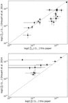 |
Fig. 2. Comparison between the integrated IR AGN and SF luminosities computed in this paper compared to the results of Drouart et al. (2014). Top panel: comparison between the infrared luminosity of the AGN; bottom panel: comparison between the infrared luminosity of the starburst or star forming component. In both panels, the dashed line is the one-to-one relationship between luminosities. |
We compare the star-forming models in this paper and those from Drouart et al. (2014) The differences are predominately due to having data in the rest-frame submm which is more sensitive, has higher spatial resolution, and covers a wider wavelength range. As can be seen from the SED shapes of the starburst/ star-forming components, they differ both in the presence of PAH features in the Drouart et al. (2014) models, and sometimes in the overall shape depending on which starburst template is used (Fig. 3). The PAH features do not contribute significantly to the total integrated  . However, in general when it comes to SED fitting, the choice of template can change the integrated LIR by up to a factor of four, as mentioned in Sect 4.4 of Drouart et al. (2014). The factor of four is estimated in the case one cannot discriminate between the most extreme starburst templates. Even in the less extreme case, there is still a factor of ∼2 between the sets of templates that are consistent with the same data points. The SED parameters that influence this difference include the assumed dust temperature, opacity and emissivity (see also Fig. 8 of Casey et al. 2018, who show how different templates can give the same integrated IR luminosity). The bottom right panel of Fig. 3 illustrates the importance of having at least one sensitive measurement on the Rayleigh-Jeans side of the emission peak, even when there are multiple detections near the peak of the SED. In this HzRG MRC 0211−256, the observed ALMA band 6 flux is 10× lower than the predicted flux in the Drouart et al. (2014) model.
 |
Fig. 3. Model comparison between the SF and AGN models of this paper and Drouart et al. (2014) for galaxies MRC 0350−279 (top left panel), MRC 0251−273 (top right panel), MRC 0156−252 (bottom left panel) and MRC 0211−256 (bottom right panel). In each plot, the black solid lines represent the synchrotron emission, dotted lines indicate the FIR thermal emission due to star-formation, and dash-dotted indicates the best-fit MIR emission due to the AGN as determined from the best fits to the photometry for each galaxy. The red lines with the same styles represent the same components as fitted in Drouart et al. (2014) A synchrotron power-law was not fit in the analysis of Drouart et al. (2014) |
We identify four general categories where the SED fits lead to significant differences in  between the two studies: (1) only upper limits in the FIR; (2) one detected ALMA component and upper limits in the rest of the FIR bands; (3) two spatially resolved detections in the ALMA bands; and (4) when the FIR consists mainly of detections. It is clear that there are cases where the differences are not significant (e.g., MRC 0156−252). However, in some cases, isolating a sub-component in high resolution, 0.″3, sensitive ALMA imaging leads to a significantly lower
  which simply is not possible using only the low-resolution Herschel data (e.g., MRC 0251−273). There are also cases where significantly deeper ALMA data (≳10× deeper than any previous submm/mm observations) still does not detect any emission (e.g., MRC 0350−279). Accordingly, our limits on
  are also much more stringent, but formally still consistent with the shallower upper limits of Drouart et al. (2014) Furthermore, we also include a more robust extrapolation of the synchrotron component due to now including the ALMA and ATCA ∼90 GHz data.
As mentioned above, it is important to note that the choice of template can change the  by ∼2 even with good photometric coverage of the peak of the thermal dust emission. In our sample, six sources have ≥3 FIR detections from Herschel and LABOCA. Out of these six, three have good agreement in the infrared luminosity, having ratios of 0.72–0.89, with Drouart et al. (2014). One is an ALMA source with multiple components, MRC 0943−242, which explains the large difference in
  . Only two sources, MRC 0211−256 and 4C 03.24, have poor agreement due to differences between a modified blackbody and the starburst templates used in Drouart et al. (2014). Considering that Drouart et al. (2014) found a potential difference of ∼2 within the templates used in their study, it is to be expected that we are finding a factor of two to three difference compared to their results for a few of our sources, especially when we also include an additional ALMA data point that constrains the Rayleigh–Jeans side of the emission peak.
Quantitatively, we find that our estimated far-infrared luminosities of the component due to star formation are only a fraction of those found by Drouart et al. (2014; Fig 2 and Table 6). If we only include detections, we find that our estimates of  are only ∼50% of those estimated in Drouart et al. (2014) If we also include detections and upper limits of
  in either of the two papers, then our estimates are only ∼40% of those in Drouart et al. (2014; Table 3). We discuss the implications of these significantly lower
  in Sects. 5 and 6. If we compare all the sources together and estimate the median IR luminosity including upper limits of the overlapping 25 sources in both studies, we find our IR luminosities are a factor ∼7 lower2.
4.5. Notes on the stellar masses
Given the importance of stellar masses in our analysis, we briefly discuss the nature of the mass estimates we are utilizing. All stellar masses used in this paper are based on those estimated in Seymour et al. (2007), De Breuck et al. (2010), Drouart et al. (2016). Our stellar masses are based on 6-band Spitzer photometry covering 3.6–24 μm, augmented with near-IR imaging. The AGN in our sample may contribute flux to the optical to mid-IR photometry used to determine the stellar masses. AGN emission contributes from both direct and scattered continuum (dominating at λrest< 1 μm), and dust emission from the torus (dominating at λrest > 5 μm). Our sample is composed of Type-2 AGN where the direct AGN contribution is obscured by the dusty torus. One exception, MRC 2025−218, has a SED which is consistent with AGN-dominated continuum emission and thus, although it is detected in the photometry used to estimate masses, we assume its stellar mass is an upper limit. Spitzer photometry used in Seymour et al. (2007) and De Breuck et al. (2010) allowed them to extrapolate the hot dust emission from the AGN down to rest-frame 1–2 μm where the old stellar population peaks. The stellar masses of objects where this hot dust contribution may dominate are conservatively listed as upper limits.
In the remaining objects, De Breuck et al. (2010) derived the stellar masses assuming a maximally old stellar population. While such estimates are reasonable, they may slightly over-estimate the masses (for a detailed discussion, see Seymour et al. 2007). To remedy this, Drouart et al. (2016) combined the Spitzer data with existing optical and near-IR photometry on a sub-sample to perform a multi-component SED fitting through population synthesis. In cases of overlap, we use the stellar masses derived by Drouart et al. (2016). The paper from which each mass estimate is taken is indicated in Table 5.
Integrated AGN and SF luminosities.
Average ratio of IR luminosities of this paper (denoted as  ) and those from Drouart et al. (2014, denoted as
  ).
).
5. Relationship between radio galaxies and their supermassive black holes
We can now compare the relative growth rates of both galaxies and their central supermassive black holes, using estimates of the star-formation rates and the mass accretion rates, respectively. Such an investigation addresses the question of how galaxies and black holes evolved to the black hole mass-bulge mass relation we observe locally (Magorrian et al. 1998; Gebhardt et al. 2000; Ferrarese & Merritt 2000; Häring & Rix 2004). We have already discussed this issue for radio galaxies in Drouart et al. (2014), so we only briefly highlight how our results reinforce the conclusions of that paper. The differences between our approach and the one of Drouart et al. (2014) are detailed in Sect. 4.4. Other than these differences, we follow the analysis of Drouart et al. (2014) quite closely, that is, we use the same conversion factors between IR luminosities and SFR and AGN accretion rates, and a very similar SED to determine the AGN luminosities (see Fig. 1 and 2 for a direct comparison).
5.1. Determining growth rates of star-formation and SMBH
To estimate the star formation rates of galaxies, we use the conversion factor from Kennicutt (1998):
using a Salpeter (1955) IMF. For consistency when comparing the SFR with stellar masses from Drouart et al. (2014) and De Breuck et al. (2010), we divide these estimates by a factor of 1.5 to convert from a Salpeter IMF to a Kroupa IMF. Our new data and fitting have resulted in significantly lower star-formation rate estimates for some sources compared to Drouart et al. (2014). If we only consider the 25 sources in common, the median star-formation rate as estimated by Drouart et al. (2014) is 760 M⊙ yr−1. The SFR for our sample span from about 40 to ∼2000 M⊙ yr−1 with a median3 value of 110 M⊙ yr−1 (Table 5). Our star-formation rates are seven times lower than previously estimated by Drouart et al. (2014) for the same sources.
To convert  to black hole accretion rate
  , we follow Drouart et al. (2014):
where the efficiency factor ϵ = 0.1 and the bolometric correction factor  . We refer to Drouart et al. (2014) for a more detailed discussion. A large fraction of the sample lies above the one-to-one line between the
  and
and  , showing that the FIR emission from the SF component is generally much weaker than the luminosity of the AGN. This is consistent with other samples of powerful AGN (e.g., Netzer et al. 2014, 2016; Stanley et al. 2015)
5.2. Relative growth rates of galaxies and SMBHs
What are the relative growth rates of the stellar and black hole mass? To make this comparison, we simply scale the IR luminosities of each component as just described. If the galaxies evolve along the local relation, we would expect the accretion rate,  , to be about ∼0.2% of the SFR (we chose 0.2% to be consistent with Drouart et al. (2014) and is within the uncertainty of estimates in the literature at the time; see Kormendy & Ho 2013). Of course, there are many assumptions that must be made in order to use these relations and one should be aware that the empirical relation is really between integrated IR luminosities,
  and
and  , with scaling factors. Nevertheless, we find that our sample lies more than an order of magnitude above the local parallel growth relation of 0.2% (Fig. 4). This suggests that the black holes can become overly massive relative to their host galaxies if the accretion time spans the same time scale as the star formation. In fact, given that the host galaxies are already massive, it is likely that this implies that the SMBHs are overly massive at the epoch they are observed.
 |
Fig. 4. Estimated AGN luminosity, |
In Drouart et al. (2014), we argued that for the growth of the host galaxy and SMBH to ultimately be consistent with the local relation, the on-going star formation would have to last about a factor of eight longer than the observed level AGN activity. Shifting  downwards by about a factor of seven, now implies that the star formation must last over a factor of 50 longer. If the lifetime of the radio loud phase is ∼25 Myrs (Martini & Weinberg 2001; Schmidt et al. 2017), this would suggest that the star formation has to last more than a Gyr. Since we predominately have upper limits for the star formation rates of the majority of the galaxies, this appears unlikely. There is evidence at high redshift that perhaps SMBHs are already overly massive compared to their host galaxies, where overly massive means that they do not have the local value of the black hole mass to spheroidal mass ratio (e.g., Nesvadba et al. 2011; Wang et al. 2013; Willott et al. 2015; Trakhtenbrot et al. 2015; Shao et al. 2017; Vayner et al. 2017, but see Willott et al. 2017). Thus, the time required for the stellar mass to “catch up” to the mass of the SMBH is actually much longer than we have estimated here. Our new results therefore exacerbate the problem already discussed in Drouart et al. (2014) that it appears difficult for the mass ratio of the SMBH and the spheroidal component of the radio galaxies to fall on the local relation through star formation. We caution however that the average black hole accretion rates over longer time scales of star formation are not well constrained by the relatively instantaneous estimates provided here and in Drouart et al. (Hickox et al. 2014; Stanley et al. 2015; Volonteri et al. 2015a).
5.3. Keeping up with rapid SMBH growth
The host galaxies of HzRGs need to catch up with the growth of the SMBH, as they appear to be already overly massive. In order to end up on the local mass relationship, the stellar component needs to grow through a mechanism that does not fuel substantially the supermassive black hole. In the following sections, we discuss the possibility of growth by mergers as a way to explain how the sample of high-z galaxies in our study can evolve on to the local relationship.
5.3.1. Growth through major mergers
High redshift powerful radio galaxies like the ones studied here are found in environments which are over-dense (e.g., Wylezalek et al. 2013; Hatch et al. 2014; Dannerbauer et al. 2014; Cooke et al. 2015, 2016; Noirot et al. 2016, 2018). In such environments, mergers are likely an important mode of galaxy growth. However, a few caveats must be kept in mind when considering galaxy mergers as the mechanism allowing galaxies and SMBHs of powerful radio galaxies to evolve onto the local mass relation. The first requirement is that mergers do not bring substantial amounts of gas to grow the SMBH significantly compared to the mass of the accreted stars. Major mergers, which may increase the stellar mass considerably, would have to be gas poor galaxies as major mergers can carry gas efficiently to small scales (kpc-scales) through dissipation which may lead to significant black hole growth. Generally, massive galaxies at high redshift, those that would constitute major mergers for radio galaxies, are gas-rich (e.g., Bolatto et al. 2015; Noble et al. 2017; Emonts et al. 2018). So unless massive galaxies within the over-dense environments of radio galaxies are particularly gas poor (see e.g., Emonts et al. 2014, 2018; Lee et al. 2017; Dannerbauer et al. 2017) then major mergers do not appear to be particularly favored for growing the stellar content of radio galaxies. Having said that, the quenching time of moderately massive galaxies in clusters is likely a small fraction of the Hubble time (e.g., Muzzin et al. 2012; Foltz et al. 2018) but with reduced efficiency with increasing redshift (Nantais et al. 2016, 2017). The second significant problem with major mergers as the driver of the stellar growth is that the merging galaxy likely also contains a supermassive black hole. In the early universe, the merger partner may have a black hole that is massive relative to the mass of its host (e.g., Willott et al. 2015). After the merger has advanced to the coalescence stage of the merger, which occurs in a few dynamical times of the most massive galaxy, the black holes will merge in less than a Hubble time (≲1 Gyr for M⋆∼1011 M⊙, which is approximately the stellar masses of our galaxies; Berczik et al. 2006; Merritt et al. 2007) A final, but perhaps less important limitation in such a picture is that the relative velocities of the merging galaxies should be relatively low, of-order the internal dynamical velocity of the stars in the most massive galaxy. Thus, relative low speed encounters are favored for efficient merging. In the over-densities surrounding the high redshift radio galaxies, the dispersion of the most massive galaxies in the potential appears to be high (Kuiper et al. 2011; Noirot et al. 2018).
5.3.2. Growth through minor mergers
Minor mergers may be an effective way to allow the mass of old stellar populations to grow in massive galaxies without fueling significant SMBH growth. There are several pieces of evidence that suggest hypothesizing that minor mergers contributed significantly to the stellar mass growth of massive galaxies. High resolution imaging suggests that there may be low mass galaxies in the surroundings of some radio galaxies (Miley et al. 2006; Seymour et al. 2012). So the potential merging sources are close at hand. Beyond just the necessary association of low mass galaxies, there are a number of lines of evidence that support the notion that massive early-type galaxies grew substantially through minor mergers. Some of these are: (1) the size evolution of massive galaxies in the early Universe to the present may be driven principally through minor mergers (e.g., Daddi et al. 2005; van Dokkum et al. 2008; Delaye et al. 2014; Vulcani et al. 2016; Hill et al. 2017); (2) the change in the mass and luminosity function of galaxies with redshift and as a function of environment (e.g., Ilbert et al. 2013; Sarron et al. 2018); (3) the elemental abundance ratios, abundance gradients, and age gradients in the outer regions of local massive spheroids are consistent with accreting galaxies with a range of masses, perhaps predominately low mass, which had their star formation truncated early in their growth (Huang et al. 2013; Greene et al. 2013; Barbosa et al. 2016); and (4) the mass of massive early-type galaxies grew by about a factor of four over the last ∼10 Gyr (e.g., van Dokkum et al. 2010; Ilbert et al. 2013).
Interestingly, Hill et al. (2017) identified the epoch at which the stellar growth of very massive galaxies, M⋆≳1011.5 M⊙, transition from growing substantially through star formation to one where mergers dominate the stellar mass growth. This is at the low redshift end of the objects in our study but is overall consistent with the quenching we observe. Moreover, at the average redshift we are observing our sample, they also find a factor of three increase in the stellar mass, which again is similar to what is needed to close the gap between the mass of the supermassive black holes and the host galaxies (see also van Dokkum et al. 2010; Vulcani et al. 2016). Both the fossil record in nearby massive galaxies and their in situ evolution suggest that minor mergers played a role in their stellar mass growth and physical properties (e.g., Greene et al. 2013; Hilz et al. 2013; Laporte et al. 2013; Hirschmann et al. 2015).
5.3.3. A comparison with BCGs and X-ray-selected AGNs
Radio galaxies lie in over-densities and have been suggested to be progenitors of brightest cluster galaxies (BCGs; Hatch et al. 2014), a more relevant comparison is not with the general properties of massive galaxies but the stellar mass growth of BCGs. Statistical samples of BCGs are limited to redshifts lower than about 1 which is lower than the median redshift of our sample, z ∼ 2.4. Results from these studies suggest that BCG typically grew by about a factor of two over the last 8–10 Gyrs (Aragon-Salamanca et al. 1998; Bellstedt et al. 2016). Overall, these growth rates are consistent with semi-analytic models which indicate that, since about z ∼ 1 − 1.5, BCGs grew by about a factor of 2–4 (De Lucia & Blaizot 2007; Tonini et al. 2012). However, any theoretical result explaining the growth of BCGs is sensitive to the treatment of dynamical friction and tidal stripping through galaxy-galaxy interactions as galaxies move through the cluster potential (e.g., Shankar et al. 2015). We conclude that if some of the galaxies in our sample are destined to become BCGs, then our overall current understanding of the stellar growth of these massive clusters galaxies is consistent with closing the difference in relative masses of the supermassive blackholes and their host galaxies.
Other samples, such as X-ray selected AGN, show a range of relative growth rates of SMBH and host galaxies. Some studies, like those that select star forming galaxies and then investigate their black hole accretion rates (using amount of X-ray emission observed above that expected that due to galaxy stellar populations) and SFR, find that black holes and galaxies are growing in lock-step (e.g, Delvecchio et al. 2015). Similarly, some studies of X-ray selected AGN with a wide range of AGN bolometric luminosities that black holes and galaxies grow in lock-step (z ∼ 2, e.g., Mullaney et al. 2012). But such results are not found universally. Netzer et al. (2016), again for an X-ray selected sample of AGN, but now at somewhat higher redshifts than previous studies, find that SMBHs are growing more rapidly on average than their hosts. Cisternas et al. (2011) find that there is no evolution in the black hole-to-galaxy mass ratio out to z ∼ 1, except perhaps for high mass black holes where black holes are overly massive relative to their host galaxies. Could the variety of results be simply due to the mass of both the galaxy and the SMBH (Cisternas et al. 2011)?
6. SFR and main sequence comparison: on the road to quenching
The main sequence of star-forming galaxies – the empirical relation between the star-formation rate and stellar mass with a slope of approximately 1 and a scatter of about a factor of two – has been studied extensively both theoretically and observationally (the MS, e.g., Brinchmann et al. 2004; Noeske et al. 2007; Elbaz et al. 2007; Daddi et al. 2007; Santini et al. 2009, 2017; Peng et al. 2010; Whitaker et al. 2012; Stark et al. 2013; Speagle et al. 2014; Lehnert et al. 2015; Davé et al. 2016; Lee et al. 2018; López Fernández et al. 2018; Davidzon et al. 2018). The relation is observed over a wide redshift range, z ∼ 0 − 7, and its normalization increases with increasing redshift. The MS has often been parameterized as a simple power-law but there has also been evidence that the MS flattens at higher stellar masses (e.g Whitaker et al. 2014; Lee et al. 2015, 2018; Tasca et al. 2015; Schreiber et al. 2015; Tomczak et al. 2016). The slope of the MS and the turnover mass in the case of a flattening MS depend on the sample selection, redshift range and the technique used to determine the stellar mass and SFR. The estimated turnover stellar mass is ∼1010 − 1010.5 M⊙ (e.g., Schreiber et al. 2015). The MS can be used to study and classify galaxies according to their relative SFR, where large deviation from the MS suggests that galaxies are “starbursts” if they lie above the MS, or quenched, if they fall below the MS. The definition of whether a galaxy is a starburst or is quenched varies in literature, but is often taken as either offset by more than three times the scatter or a factor of ten above or below the mean relation (e.g., Rodighiero et al. 2011). We now compare our sample of HzRGwith the MS and discuss what the implications are now that we include spatially-resolved FIR ALMA data and account for possible contamination from synchrotron emission.
6.1. Comparison with the MS and impact of submm spatial resolution
Our sample of radio galaxies has a wide range of relative SFR compared to galaxies which lie along the MS (Fig. 5; Schreiber et al. 2015; Santini et al. 2017). Unfortunately, the number of possible MS parameters such as slope, zero-point, and whether or not the MS was fitted with a turnover at high stellar masses makes a direct comparison with our results challenging. To make matters worse, there are additional potential differences in the methods and wavelength range used to estimate stellar masses and SFR, the range of stellar masses studied, and, for consistency with the broad redshift range of our sample, the redshift range that any individual study covered. For example, Santini et al. (2017) redshift span of 1.3 < z < 6 and stellar mass range, ∼107.5 − 1011 M⊙. Our masses are generally higher than their upper mass limit. Schreiber et al. (2015) span stellar masses from ∼109 to 1011.3 M⊙, which makes their mass range comparable to the radio galaxies in our sample. Unfortunately, their redshift range is rather limited, 0.5 ≤ z ≤ 2.5, for making a robust comparison with our sample difficult. Of course, these limitations are purely observational depending on the depth and area covered by the surveys from which these results are derived. Our HzRG sample consists of the rarest, most massive galaxies selected from all sky radio surveys. HzRGs thus allows us to extend MS studies to the most massive end of the galaxy mass distribution, and as now discussed, our comparison suggests that the HzRGs in our sample fall either on or below the star-forming MS (Fig. 5).
 |
Fig. 5. Relationship between the SFR and stellar mass for different redshift bins. The colored shaded regions shows the MS of Santini et al. (2017) for each respective redshift bins with a 0.3 dex scatter around the MS. The gray shaded regions shows the MS with a 0.3 dex scatter from Schreiber et al. (2015), with a turnover at higher stellar masses. Our stellar masses have been scaled from a Kroupa to a Salpeter IMF to be consistent with the IMF used to make the MS in this comparison. In the highest redshift bin, 3 < z < 4, two sources, TN J1338+1942 and TNJ0924−2201, have been added to the right most panel despite having redshifts outside of the range used to construct the MS (z = 4.110 and 5.195 respectively). Given the redshift dependence on the normalization of the MS, these galaxies may lie relatively lower in comparison with the mean relation of a MS derived using galaxies over a more appropriate, higher redshift range (see Fig. 6). |
We first compare our results with the MS from Schreiber et al. (2015), gray regions in Fig. 5), covering 0.5 < z < 4 and for M* = 1011.33 M⊙, close to the mean stellar mass of 1011.35 M⊙ of our sample. In comparison to Schreiber et al. (2015), who fits a turnover in the MS at high stellar masses, we find two sources lie above, 14 sources lie within the 0.3 dex scatter of the MS, and nine lie below the MS. We note however, that three of the sources that lie along the MS have only upper limits in their estimated SFR. In addition, two sources have uncertainties in their SFR estimate, which give them a significant probability of lying below the MS. All of these sources could well lie below the MS. Thus, in comparison with the results of Schreiber et al. (2015), we find that the galaxies in our sample generally fall below the main sequence.
Since (Schreiber et al. 2015) fit their data in the SFR-stellar mass plane with a function that has a turnover, comparing our results with a study that does not allow for such a turnover, may result in a change in how we characterize our results. We therefore also compare our results with the MS from Santini et al. (2017), which does not include such a turnover (colored regions in Fig. 5). We again find that our HzRG sample significantly lies below the MS. None of our sources lie above the MS of Santini et al. (2017), six sources lie along the MS, five sources lie at at the lower ± 0.3 dex boundary, and six sources lie below. The remaining seven sources have upper limits in SFR, and may well lie below the MS of Santini et al. (2017). At any rate, the comparison with both Schreiber et al. (2015) and Santini et al. (2017) suggest that many of our sample galaxies lie below the MS and are consistent with being quenched.
Three out of the four galaxies with the highest SFR in our sample and which lie on or above the MS, TN J0121+1320, MRC 0152−209, PKS 0529−549, and TN J1338−1942, have morphological features in the ALMA continuum suggesting that perhaps they might be mergers (we indicate these four sources by name in Fig. 5 to highlight the fact that they are high in the SFR-stellar mass plane compared to the other galaxies in our sample). The Dragonfly galaxy, MRC 0152−209, has two clearly interacting mm components. Indeed, for this source there is strong evidence that the dynamics of this system are consistent with a strong interaction of three components with significant mass transfer between them (Emonts et al. 2015a,b). Both TN J0121+1320 and PKS 0529−549 have elongated shapes which are different from the synthesized beam, which in analogy with the Dragonfly galaxy, is consistent with them being mergers. We would need (sub-)mm line kinematics and continuum morphology at higher resolution to know definitively whether or not they are mergers. TN J1338−1942 is unresolved in our data and, within this criterion, is not consistent with being a merger.
We can also compare the sSFR our sample with that of the ensemble of star-forming galaxies as a function of redshift (Fig. 6). Just as with our comparison with main sequences at various redshifts, we find that a large fraction of our sample falls below the main sequence and its evolution. To be conservative, we made this comparison with the MS evolution estimated in Schreiber et al. (2015), which includes a turnover in their fitting of the MS. Even though the galaxies are massive and lie above the mass at which the turnover starts and the MS flattens, our galaxies generally lie below. Of course, if we used main sequences that do not allow for a turnover in the stellar mass-SFR relation, then the difference between our sources and the evolution of the MS at constant mass would be even more dramatic. We note that since the slope of the MS is about one and if there is no flattening in the MS at high stellar masses, then the exact mass used for comparison with the radio galaxies is not particularly important.
 |
Fig. 6. Specific star formation rate, sSFR (Gyr−1), as a function of redshift. The black filled circles, black arrows and purple arrows represent the radio galaxies of our sample that are detected, detected but with unconstrained SF component and undetected with ALMA, respectively. The diamonds indicate sources which have both upper limits on the stellar mass and the SFR. The shaded region shows the galaxy main sequence (adapted from Schreiber et al. 2015) for M* = 1011.33 M⊙. We only indicate the redshift range 0.5 < z < 4 in the shaded region as z = 4 is the redshift limit of the objects studied in (Schreiber et al. 2015). We do not extrapolate to higher redshifts (Stark et al. 2013). |
Our results are different from previous studies. In previous studies massive high redshift radio galaxies have often been associated with high BH accretion rate combined with high SFR because they are extremely luminous in both the mid-IR (Ogle et al. 2006; Seymour et al. 2007; De Breuck et al. 2010) and the sub-mm (Archibald et al. 2001; Reuland et al. 2003; Stevens et al. 2003). Not surprisingly given the sensitive upper limits or finding that synchrotron emission may dominate the emission at mm wavelengths, our star formation rate estimates are lower than those found by other studies. On the other hand, our results on the AGN-heated dust luminosity are consistent with previous studies, which is not surprising given that we are using the same or similar data. Our finding that HzRGs fall mainly along or below the MS is therefore new. Most of the sources lying below the MS relation are non-detections in the ALMA band, and often not detected in the SPIRE bands either. These galaxies have very low SFR and are an order-of-magnitude weaker then what was previously estimated. These galaxies are not star forming, they are on their way to being quenched.
6.2. Comparison with X-ray selected high redshift AGNs
Naturally, given the importance of understanding the relation between the growth of the stellar population of galaxies and the influence of AGN, it is useful to compare our results for the star-formation rates of powerful high redshift radio galaxies with those of other types AGN. Within the perspective of the overall population of AGN, it is not clear exactly what the role of the AGN is in quenching the star formation. We find that many of our sources do not currently have significant star formation. Our upper limits, constraining the median SFR to be ∼100 M⊙ yr−1, are also consistent with little or no star formation, especially for those sources with upper limits in the Herschel bands and (likely) only synchrotron emission in the mm. As we already discussed, the typical lifetime of AGN is of-order a few 10 Myrs. The IR and sub-mm thermal dust emission probes star formation, past and present, over timescales of 100 Myrs or more (i.e., comparable to a few internal dynamical times of the galaxies; Lehnert & Heckman 1996; Boquien et al. 2014, 2016). These differing timescales implies that unless the AGN are significantly longer lived than we currently understand them to be, the luminous or mechanical output from AGN is unlikely to be the sole mechanism for shutting down star formation in these galaxies.
We can perhaps understand this by comparing the results of studies of the AGN influence on the star formation within their hosts. In Fig. 7, we show such a comparison focusing on X-ray selected AGN from various studies (based on a similar figure in Netzer et al. 2016, but see also Rosario et al. 2012; Stanley et al. 2015, 2017 for earlier or different renditions of the same plot). Our galaxies lie at the upper end of the distribution of AGN luminosities and their total infrared luminosities are dominated by the emission from the AGN they host. Generically, our host galaxies are forming stars at a much lower rate on average than the X-ray selected AGN, at least for those that have well determined star formation rates. Netzer et al. (2016) found that if they stacked the X-ray selected AGN without detections in the infrared results in a much lower mean IR luminosity due to young stars. This stacked luminosity and the implied SFR is comparable to our sample. These final results may suggest that the key parameter in the difference in differential growth rates of actively fueled SMBHs is in fact is the luminosity of the AGN. All of our sources and those of Netzer et al. (2016) are among the most luminous at their respective redshifts.
 |
Fig. 7. Comparison of our results in the LSF − LAGN plane to other studies. |
Such an hypothesis would explain a wide range of results. If we focus on studies that sample a wide range of AGN bolometric or IR luminosities and estimated SFRs, the evidence points to both the AGN and galaxies growing in lock step (Mullaney et al. 2012; Rovilos et al. 2012; Delvecchio et al. 2015) and there is generally no widespread evidence for quenching (e.g., Harrison et al. 2012; Rosario et al. 2013; Stanley et al. 2017). However, one has to be cautious in these simple relations between galaxies being on the main sequence and the impact of AGN on their star formation rates. The effect of AGN on star formation rates may be subtle and may also influence the control sample of galaxies without active black holes. Scholtz et al. (2018) make the interesting point that the star-formation rate distribution at constant mass of galaxies with or without AGN is similar, and this result actually agrees with simulations. They suggest that the agreement between AGN and non-AGN in lying on the same relation in the SFR-stellar mass plane is because the impact of AGN is evident in both samples, and it is this effect that is driving the slope of decreasing sSFR with increasing mass (see also Mainieri et al. 2011). So the effect of AGN feedback is subtle, broadening distributions and not necessarily correlating with AGN power/luminosity as might be naively expected. In a study similar to ours, Mullaney et al. (2015) used ALMA observations of X-ray selected AGN, finding that the estimated SFRs were lower relative to previous findings. This reduction lead to AGN hosts having a different distribution than the star forming galaxy population, meaning the AGN population of star forming galaxies had a broader, and perhaps even offset distribution of star formation rates (Rovilos et al. 2012; Rosario et al. 2015).
6.3. A significant synchrotron contribution in submm
Our high resolution ALMA data allowed us to do component separation such that the contribution of synchrotron to the mm emission is now clear, originating from radio lobes and the nuclei. For nine out of 25 sources, the best-fit SEDs of specific spatial components are consistent with a power-law extrapolation from radio frequencies. These spatial components are likely dominated by synchrotron emission. The total flux of five galaxies, not just the lobes, are associated with pure synchrotron emission and are consistent with no contribution from thermal dust emission. For two host galaxies, which have two spatially-resolved emission components in the ALMA band, the majority of the mm-flux is due synchrotron with only a minor contribution from thermal dust emission.
It is surprising to find our high frequency data is consistent with an extrapolation of the synchrotron intensities in the radio (Jaffe & Perola 1973; Carilli et al. 1991; Blundell et al. 2006). The energy loss though aging of the electrons and inverse Compton scattering should steepen the observed spectrum at higher frequencies. But what we see in a few sources is that the synchrotron spectrum continues straight out to high frequencies (e.g., Gopal-Krishna et al. 2001). One possible explanation is that the electrons are continuously accelerated within the lobes, perhaps through strong oblique shocks (e.g., Summerlin & Baring 2012). The details and analysis of the radio spectra including ALMA synchrotron detections will be presented in a subsequent study.
6.4. Star formation and radio source sizes
The spatial separation of the emission from the radio lobes – the projected distance between the two lobes or between the core and lobes – can provide useful constraints on the nature of the AGN. The separation, if the sources expand at constant velocity, can be used as a proxy for the age of the radio source (e.g., Carilli et al. 1991). Larger sources correspond to older sources. A possible test of a scenario where the AGN is the agent driving the quenching of star formation is that galaxies with the lowest star formation rates have the largest radio sources. In fact, we do see a possible trend between the largest angular size of a radio source and the predominance of upper limits to the star formation rates (Fig. 8). This trend is robust in the sense that high significance estimates of the SFR all appear below largest angular sizes of ∼3 arcsec. At the typical redshifts of our sources, this corresponds to approximately 10–15 kpc in radius, or about the expected extent of the interstellar medium of a massive galaxy. We do not have a sufficient number of sources or sensitive enough upper-limits to say that there is a correlation. Such a correlation would be interesting, as it would support a simple model of propagating jets that may enhance star formation when they are still confined within the host galaxy, but then quickly preventing further star formation after they break out.
 |
Fig. 8. Star formation rate, SFR in M⊙ yr−1, versus the projected physical size of the radio emission in kpc, calculated using the largest angular size (LAS) of the radio emission at 1.4 GHz (De Breuck et al. 2010). Black filled circles are detections, black arrows detections but with unconstrained SF component and purple arrows non-detections (see text for details). |
Timescale arguments may also complicate the comparison between radio size and SFR. The duration of AGN activity is thought be around 107–108 yrs (e.g., Martini & Weinberg 2001; Hopkins et al. 2005; Schmidt et al. 2017). The star formation likely lasts much longer. Other than observing a proclivity for the upper-limits in the SFR to be associated with radio sources larger than the host galaxy proper, it may not be that surprising that we do not see a very clear correlation. There are several factors that may influence the rate at which radio jets expand into the surrounding media. Perhaps the most important is the environment into which the jets are expanding. For jets which propagate outwards into denser environments, the radio source may be confined and can either simply expand more slowly, or can decelerate (Shabala et al. 2017). There may not be a simple linear relationship for individual sources and they may not all take the same amount of time to reach the same size. There are also of course projection and beaming effects to consider. Since we observe a wide range of SFRs, radio morphologies, and lobe asymmetries in this sample (De Breuck et al. 2010), it is likely that the characteristics of the surrounding environments of the individual radio sources play a significant role in determining the scatter in this relation. Moreover, given that the star formation is expected to occur on time scales longer than the duration of the AGN activity perhaps not seeing a clear cut correlation is not unexpected, regardless of the processes that can influence radio source sizes and morphologies. Other effects may play a role since the galaxies in our sample with high SFRs, have morphologies consistent with being mergers (Sect. 6).
7. Possible interpretation of our results
Our interpretation of our results is that: (i) the quenching we observe for the majority of the sample is naturally explained by our galaxies predominately being at the high mass end of the galaxy population (Ilbert et al. 2013) and having very massive SMBHs (Nesvadba et al. 2011). We know that such galaxies in the local universe must be quenched rapidly and soon after their most substantial period of growth (e.g., Thomas et al. 2005, 2010). They also likely grew subsequently, after they are quenched, through the accretion of relatively low mass, likely gas-poor galaxies (e.g., Greene et al. 2013). Thus, we can say that their quenching is mainly a result of the fact that they are already massive only a few Gyrs after the Big Bang; and, (ii) given the fact that some of galaxies in the sample of high redshift radio galaxies have intense star formation and young stars (Dey et al. 1997, Man et al., in prep.), it is likely that star formation played a key role in quenching the host galaxies of distant radio galaxies. This is a natural conclusion, given that the AGN are likely only luminous for 10 s of Myrs (Schmidt et al. 2017), which is generally shorter than we would expect bursts of star formation to last. Other samples of AGN with lower host masses have substantial outflows (e.g., Harrison et al. 2016), and are not generally quenched.
It is difficult to isolate the impact of mass and environment on the rate and timing of quenching. Mass quenching is more important at earlier times in the evolution of galaxies and may be more important in denser regions (e.g., Peng et al. 2010; Muzzin et al. 2012; Lee et al. 2015; Darvish et al. 2016, 2018; Kawinwanichakij et al. 2017). And in the case of powerful radio galaxies, which lie in over-dense environments, both gas-rich and gas-poor mergers likely play an important role in both the growth of the stellar mass and the black holes. Volonteri et al. (2015b) suggest that in the merger phase, the AGN dominates the bolometric luminosity but the accretion can be very stochastic (see also Gabor & Bournaud 2013; DeGraf et al. 2017). It appears that the galaxies in our sample with the highest star-formation rates all host very powerful AGN, and are potentially all advanced mergers, consistent with this picture. In fact, PKS 0529−549, which has one of the highest SFRs of all the galaxies in our sample, has a modest gas fraction of about 15%, a high star-formation efficiency (SFR/molecular gas mass), and has been transforming its gas into stars rapidly (Man et al., in prep.). The star formation efficiencies in the other radio galaxies with high SFRs also appear extreme (10–100 Gyr−1; Man et al., in prep.). But of course, that does not explain our results in themselves. Dubois et al. (2015), in a study using numerical simulations of the relative growth of SMBHs and their host galaxies, found that star formation may regulate the black hole accretion rate. During the most rapid, gas-rich phase of the growth of massive galaxies, it may be that a larger fraction of the gas in the ISM is not available to fuel the SMBHs, but is consumed via star formation (see DeGraf et al. 2017). As the gas fractions decline, the relative power of the AGN compared to that of the star formation increases, resulting in an increased star formation efficiency. Concomitantly, the increased star formation rate can then disperse the dense gas making it easier for the jets to drive vigorous and efficient outflows (Nesvadba et al. 2006, 2017).
So we suggest that mass is the primary difference in the characteristics of our sample of galaxies compared to other samples of AGN (see also Mainieri et al. 2011; Stanley et al. 2017). This difference makes it then much easier for the AGN to dominate the bolometric output as the SMBHs in massive galaxies may be “overly” massive for their host masses. Even relatively low accretion rates would lead to powerful AGN emission. The mechanical and radiative output from the young massive stars, heats the interstellar medium, changes its phase distribution, and puffs it up. In such a state, the coupling between the mechanical energy of the jet and heated and expanded interstellar medium of the galaxy, would be high (Biernacki & Teyssier 2018). This leads to a positive feedback loop at the end of the most rapid growth phase of massive galaxies where the residual gas of star formation is rapidly removed through the action of the AGN, leading to the rapid session of star-formation. The galaxy is on the road to being quenched.
8. Conclusions
With 0.″3 resolution mm ALMA data, and utilizing the new SED fitting tool, MR-MOOSE, we have estimated  and
and  . We have disentangled the IR luminosity into components heated by the stellar populations and that heated by the luminous AGN that reside in these host galaxies. With our deep ALMA observations, we reach depths at which we expect the thermal dust and synchrotron contributions to the mm emission to be of the same order-of-magnitude. This high sensitivity is the reason why it is essential to disentangle both spectrally and spatially the contribution from the high frequency synchrotron emission at (sub-)mm wavelengths. From a study of 25 powerful high redshift radio galaxies, our main conclusions are:
-
We find that the SFRs are lower than previously estimated, having a median which is ∼7 times lower (cf. Drouart et al. 2014). This is a result of having deep ALMA data enabling us to estimate robust upper limits, to disentangle several emission components, and determine if the mm emission represents the high frequency end of the power-law extrapolation of the radio emission. We interpret any flux density estimate that is consistent with the power-law extension from the radio to the (sub-)mm as synchrotron emission, and not as dust heated by young stars.
-
Unlike many studies of high redshift AGN, we find that a large fraction of our sources do not lie within the scatter of the relation between the stellar mass and the star-formation rate of star forming galaxies (the “main sequence”). Since the deviation of the radio galaxies with upper limits does not meet the general criterion for quenched galaxies, we interpret such galaxies as being “on their way to being quenched”.
-
Finding lower star formation rates generally exacerbates the problem of differential growth between the black hole and the host galaxy discussed by Drouart et al. (2014). This favors a scenario where the host galaxies ultimately grow by dissipationless merging which adds additional stellar mass without increasing significantly the mass of the black hole. We find that at the typical specific star-formation rates we estimate for the host galaxies, the host galaxy needs ∼50 times longer than the time over which the SMBH is active to “catch up” to having the local ratio of black hole mass to stellar mass.
-
There is no clear relation between the radio size and SFR, although we note that the upper limits on the star formation rate tend to be in sources where the LAS is larger than ∼3 arcsec. However, given that the star formation is expected to occur on time scales of the same order or longer than the duration of the AGN activity (107–108 yrs) perhaps not finding a clear cut correlation is not completely surprising even if the radio jets are driving the quenching we observe.
From these results, we suggest that mass is the primary difference in the characteristics of our sample of galaxies compared to other samples of AGN. The host galaxies of our sample of radio galaxies are generally more massive and likely harbor high mass black holes than AGN selected using other methods. Hosting more massive black holes means that it is also easier for the AGN to dominate the bolometric output of the galaxy, even if it forming stars vigorously. In order to comprehend how the host galaxies are quenching so rapidly, we hypothesize a positive feedback loop between the AGN and star formation. The star formation leads to rapid gas depletion and its intense energy input heats the remaining gas allowing the interaction between the gas and jets to be efficient. The AGN then blows away the residual gas at the end of the star formation episode. It is in this way perhaps that the host galaxies of powerful high redshift radio galaxies are “on the road to being quenched”.
For this comparison, we used a Kaplan–Meier estimator (Feigelson & Nelson 1985).
The medians were estimated using a Kaplan–Meier estimator (Feigelson & Nelson 1985).
Acknowledgments
M.D.L. wishes to thank the ESO visitors program for its continued support and Marta Volonteri and Gary Mamon for fascinating discussions. T.F. acknowledges financial support from ESO and INSU/CNRS for this work. T.F., C. De B. and M. D. L. thank Joe Silk for interesting suggestions and analysis and an anonymous referee for their constructive criticisms and suggestions. BG acknowledge support from the ERC Advanced Programme DUSTYGAL (321334) and STFC (ST/P0000541/1). This paper makes use of the following ALMA data: ADS/JAO.ALMA#2012.1.00039.S, ADS/JAO.ALMA#2013.1.00521.S, ADS/JAO.ALMA#2015.1.00530.S, and ADS/JAO.ALMA#2012.1.00242.S. ALMA is a partnership of ESO (representing its member states), NSF (USA) and NINS (Japan), together with NRC (Canada), NSC and ASIAA (Taiwan), and KASI (Republic of Korea), in cooperation with the Republic of Chile. The Joint ALMA Observatory is operated by ESO, AUI/NRAO and NAOJ. The Australia Telescope is funded by the Commonwealth of Australia for operation as a National Facility managed by CSIRO. The authors wish to express their sincerest thank you to the staff of the CSIRO for their assistance in conducting these observations and the program committee for their generous allocation of time and continuing support for our research. The National Radio Astronomy Observatory is a facility of the National Science Foundation operated under cooperative agreement by Associated Universities, Inc.
References
- Aragon-Salamanca, A., Baugh, C. M., & Kauffmann, G. 1998, MNRAS, 297, 427 [NASA ADS] [CrossRef] [Google Scholar]
- Archibald, E. N., Dunlop, J. S., Hughes, D. H., et al. 2001, MNRAS, 323, 417 [NASA ADS] [CrossRef] [Google Scholar]
- Balick, B., & Heckman, T. M. 1982, ARA&A, 20, 431 [NASA ADS] [CrossRef] [Google Scholar]
- Barbosa, C. E., Arnaboldi, M., Coccato, L., et al. 2016, A&A, 589, A139 [NASA ADS] [CrossRef] [EDP Sciences] [Google Scholar]
- Bellstedt, S., Lidman, C., Muzzin, A., et al. 2016, MNRAS, 460, 2862 [NASA ADS] [CrossRef] [Google Scholar]
- Benson, A. J., Bower, R. G., Frenk, C. S., et al. 2003, ApJ, 599, 38 [NASA ADS] [CrossRef] [Google Scholar]
- Berczik, P., Merritt, D., Spurzem, R., & Bischof, H.-P. 2006, ApJ, 642, L21 [NASA ADS] [CrossRef] [Google Scholar]
- Best, P. N., Kauffmann, G., Heckman, T. M., et al. 2005, MNRAS, 362, 25 [NASA ADS] [CrossRef] [Google Scholar]
- Biernacki, P., & Teyssier, R. 2018, MNRAS, 475, 5688 [NASA ADS] [CrossRef] [Google Scholar]
- Bithell, M., & Rees, M. J. 1990, MNRAS, 242, 570 [NASA ADS] [CrossRef] [Google Scholar]
- Blundell, K. M., Fabian, A. C., Crawford, C. S., Erlund, M. C., & Celotti, A. 2006, ApJ, 644, L13 [NASA ADS] [CrossRef] [Google Scholar]
- Bolatto, A. D., Warren, S. R., Leroy, A. K., et al. 2015, ApJ, 809, 175 [NASA ADS] [CrossRef] [Google Scholar]
- Boquien, M., Buat, V., & Perret, V. 2014, A&A, 571, A72 [NASA ADS] [CrossRef] [EDP Sciences] [Google Scholar]
- Boquien, M., Kennicutt, R., Calzetti, D., et al. 2016, A&A, 591, A6 [NASA ADS] [CrossRef] [EDP Sciences] [Google Scholar]
- Briggs, D. 1995, PhD Thesis, New Mexico Institute of Mining and Technology, USA [Google Scholar]
- Brinchmann, J., Charlot, S., White, S. D. M., et al. 2004, MNRAS, 351, 1151 [NASA ADS] [CrossRef] [Google Scholar]
- Broderick, J. W., De Breuck, C., Hunstead, R. W., & Seymour, N. 2007, MNRAS, 375, 1059 [NASA ADS] [CrossRef] [Google Scholar]
- Capak, P. L., Teplitz, H. I., Brooke, T. Y., Laher, R., & Science Center, S. 2013, AAS Meeting Abstracts, 221, 340.06 [Google Scholar]
- Carilli, C. L., Perley, R. A., Dreher, J. W., & Leahy, J. P. 1991, ApJ, 383, 554 [NASA ADS] [CrossRef] [Google Scholar]
- Carilli, C. L., Röttgering, H. J. A., van Ojik, R., et al. 1997, ApJS, 109, 1 [NASA ADS] [CrossRef] [Google Scholar]
- Casey, C. M. 2012, MNRAS, 425, 3094 [Google Scholar]
- Casey, C. M., Hodge, J., Zavala, J. A., et al. 2018, ApJ, 862, 78 [NASA ADS] [CrossRef] [Google Scholar]
- Cisternas, M., Jahnke, K., Bongiorno, A., et al. 2011, ApJ, 741, L11 [NASA ADS] [CrossRef] [Google Scholar]
- Condon, J. J., Cotton, W. D., Greisen, E. W., et al. 1998, AJ, 115, 1693 [NASA ADS] [CrossRef] [Google Scholar]
- Conley, A., Cooray, A., Vieira, J. D., et al. 2011, ApJ, 732, L35 [NASA ADS] [CrossRef] [Google Scholar]
- Cooke, E. A., Hatch, N. A., Rettura, A., et al. 2015, MNRAS, 452, 2318 [NASA ADS] [CrossRef] [Google Scholar]
- Cooke, E. A., Hatch, N. A., Stern, D., et al. 2016, ApJ, 816, 83 [NASA ADS] [CrossRef] [Google Scholar]
- Cortese, L., Ciesla, L., Boselli, A., et al. 2012, A&A, 540, A52 [NASA ADS] [CrossRef] [EDP Sciences] [Google Scholar]
- Daddi, E., Renzini, A., Pirzkal, N., et al. 2005, ApJ, 626, 680 [NASA ADS] [CrossRef] [Google Scholar]
- Daddi, E., Dickinson, M., Morrison, G., et al. 2007, ApJ, 670, 156 [NASA ADS] [CrossRef] [Google Scholar]
- Dannerbauer, H., Kurk, J. D., De Breuck, C., et al. 2014, A&A, 570, A55 [NASA ADS] [CrossRef] [EDP Sciences] [Google Scholar]
- Dannerbauer, H., Lehnert, M. D., Emonts, B., et al. 2017, A&A, 608, A48 [NASA ADS] [CrossRef] [EDP Sciences] [Google Scholar]
- Darvish, B., Mobasher, B., Sobral, D., et al. 2016, ApJ, 825, 113 [NASA ADS] [CrossRef] [Google Scholar]
- Darvish, B., Martin, C., Gonçalves, T. S., et al. 2018, ApJ, 853, 155 [NASA ADS] [CrossRef] [Google Scholar]
- Davé, R., Thompson, R., & Hopkins, P. F. 2016, MNRAS, 462, 3265 [NASA ADS] [CrossRef] [Google Scholar]
- Davidzon, I., Ilbert, O., Faisst, A. L., Sparre, M., & Capak, P. L. 2018, ApJ, 852, 107 [NASA ADS] [CrossRef] [Google Scholar]
- De Breuck, C., van Breugel, W., Röttgering, H. J. A., & Miley, G. 2000, A&AS, 143, 303 [NASA ADS] [CrossRef] [EDP Sciences] [Google Scholar]
- De Breuck, C., Bertoldi, F., Carilli, C., et al. 2004, A&A, 424, 1 [NASA ADS] [CrossRef] [EDP Sciences] [Google Scholar]
- De Breuck, C., Downes, D., Neri, R., et al. 2005, A&A, 430, L1 [NASA ADS] [CrossRef] [EDP Sciences] [Google Scholar]
- De Breuck, C., Seymour, N., Stern, D., et al. 2010, ApJ, 725, 36 [NASA ADS] [CrossRef] [Google Scholar]
- DeGraf, C., Dekel, A., Gabor, J., & Bournaud, F. 2017, MNRAS, 466, 1462 [NASA ADS] [CrossRef] [Google Scholar]
- Delaye, L., Huertas-Company, M., Mei, S., et al. 2014, MNRAS, 441, 203 [NASA ADS] [CrossRef] [Google Scholar]
- De Lucia, G., & Blaizot, J. 2007, MNRAS, 375, 2 [NASA ADS] [CrossRef] [Google Scholar]
- Delvecchio, I., Lutz, D., Berta, S., et al. 2015, MNRAS, 449, 373 [Google Scholar]
- Dey, A., van Breugel, W., Vacca, W. D., & Antonucci, R. 1997, ApJ, 490, 698 [NASA ADS] [CrossRef] [Google Scholar]
- Drouart, G., & Falkendal, T. 2018, MNRAS, 477, 4981 [NASA ADS] [CrossRef] [Google Scholar]
- Drouart, G., De Breuck, C., Vernet, J., et al. 2014, A&A, 566, A53 [NASA ADS] [CrossRef] [EDP Sciences] [Google Scholar]
- Drouart, G., Rocca-Volmerange, B., De Breuck, C., et al. 2016, A&A, 593, A109 [NASA ADS] [CrossRef] [EDP Sciences] [Google Scholar]
- Dubois, Y., Volonteri, M., Silk, J., et al. 2015, MNRAS, 452, 1502 [NASA ADS] [CrossRef] [Google Scholar]
- Elbaz, D., Daddi, E., Le Borgne, D., et al. 2007, A&A, 468, 33 [NASA ADS] [CrossRef] [EDP Sciences] [Google Scholar]
- Emonts, B. H. C., Norris, R. P., Feain, I., et al. 2011a, MNRAS, 415, 655 [NASA ADS] [CrossRef] [Google Scholar]
- Emonts, B. H. C., Feain, I., & Mao, M. Y. 2011b, ApJ, 734, L25 [NASA ADS] [CrossRef] [Google Scholar]
- Emonts, B. H. C., Norris, R. P., Feain, I., et al. 2014, MNRAS, 438, 2898 [NASA ADS] [CrossRef] [Google Scholar]
- Emonts, B. H. C., Mao, M. Y., Stroe, A., et al. 2015a, MNRAS, 451, 1025 [CrossRef] [Google Scholar]
- Emonts, B. H. C., De Breuck, C., & Lehnert, M. D. 2015b, A&A, 584, A99 [NASA ADS] [CrossRef] [EDP Sciences] [Google Scholar]
- Emonts, B. H. C., Lehnert, M. D., Dannerbauer, H., et al. 2018, MNRAS, 477, L60 [NASA ADS] [CrossRef] [Google Scholar]
- Emsellem, E., Cappellari, M., Krajnović, D., et al. 2011, MNRAS, 414, 888 [Google Scholar]
- Feigelson, E. D., & Nelson, P. I. 1985, ApJ, 293, 192 [NASA ADS] [CrossRef] [Google Scholar]
- Ferrarese, L., & Merritt, D. 2000, ApJ, 539, L9 [NASA ADS] [CrossRef] [Google Scholar]
- Foltz, R., Wilson, G., & Muzzin, A. 2018, ArXiv e-prints [ArXiv:1803.03305] [Google Scholar]
- Foreman-Mackey, D., Hogg, D. W., Lang, D., & Goodman, J. 2013, PASA, 125, 306 [CrossRef] [Google Scholar]
- Gabor, J. M., & Bournaud, F. 2013, MNRAS, 434, 606 [NASA ADS] [CrossRef] [Google Scholar]
- Galametz, M., Kennicutt, R. C., Albrecht, M., et al. 2012, MNRAS, 425, 763 [NASA ADS] [CrossRef] [Google Scholar]
- Gebhardt, K., Bender, R., Bower, G., et al. 2000, ApJ, 539, L13 [NASA ADS] [CrossRef] [Google Scholar]
- Gopal-Krishna, Subramanian, P., Wiita, P. J., Becker, P. A., et al. 2001, A&A, 377, 827 [NASA ADS] [CrossRef] [EDP Sciences] [Google Scholar]
- Greene, J. E., Murphy, J. D., Graves, G. J., et al. 2013, ApJ, 776, 64 [NASA ADS] [CrossRef] [Google Scholar]
- Gullberg, B., De Breuck, C., Lehnert, M. D., et al. 2016, A&A, 586, A124 [NASA ADS] [CrossRef] [EDP Sciences] [Google Scholar]
- Häring, N., & Rix, H.-W. 2004, ApJ, 604, L89 [NASA ADS] [CrossRef] [Google Scholar]
- Harrison, C. M., Alexander, D. M., Mullaney, J. R., et al. 2012, ApJ, 760, L15 [NASA ADS] [CrossRef] [Google Scholar]
- Harrison, C. M., Alexander, D. M., Mullaney, J. R., et al. 2016, MNRAS, 456, 1195 [NASA ADS] [CrossRef] [Google Scholar]
- Hatch, N. A., Wylezalek, D., Kurk, J. D., et al. 2014, MNRAS, 445, 280 [NASA ADS] [CrossRef] [Google Scholar]
- Hickox, R. C., Mullaney, J. R., Alexander, D. M., et al. 2014, ApJ, 782, 9 [NASA ADS] [CrossRef] [Google Scholar]
- Hildebrand, R. H. 1983, QJRAS, 24, 267 [NASA ADS] [Google Scholar]
- Hill, A. R., Muzzin, A., Franx, M., et al. 2017, ApJ, 837, 147 [NASA ADS] [CrossRef] [Google Scholar]
- Hilz, M., Naab, T., & Ostriker, J. P. 2013, MNRAS, 429, 2924 [NASA ADS] [CrossRef] [Google Scholar]
- Hirschmann, M., Naab, T., Ostriker, J. P., et al. 2015, MNRAS, 449, 528 [NASA ADS] [CrossRef] [Google Scholar]
- Hopkins, P. F., Hernquist, L., Martini, P., et al. 2005, ApJ, 625, L71 [Google Scholar]
- Huang, S., Ho, L. C., Peng, C. Y., Li, Z.-Y., & Barth, A. J. 2013, ApJ, 768, L28 [NASA ADS] [CrossRef] [Google Scholar]
- Ilbert, O., McCracken, H. J., Le Fèvre, O., et al. 2013, A&A, 556, A55 [NASA ADS] [CrossRef] [EDP Sciences] [Google Scholar]
- Ivison, R. J., Morrison, G. E., Biggs, A. D., et al. 2008, MNRAS, 390, 1117 [NASA ADS] [CrossRef] [Google Scholar]
- Ivison, R. J., Smail, I., Amblard, A., et al. 2012, MNRAS, 425, 1320 [NASA ADS] [CrossRef] [Google Scholar]
- Jaffe, W. J., & Perola, G. C. 1973, A&A, 26, 423 [NASA ADS] [Google Scholar]
- Jahnke, K., & Macciò, A. V. 2011, ApJ, 734, 92 [NASA ADS] [CrossRef] [Google Scholar]
- Kalfountzou, E., Stevens, J. A., Jarvis, M. J., et al. 2017, MNRAS, 471, 28 [NASA ADS] [CrossRef] [Google Scholar]
- Kapahi, V. K., Athreya, R. M., van Breugel, W., McCarthy, P. J., & Subrahmanya, C. R. 1998, ApJS, 118, 275 [NASA ADS] [CrossRef] [Google Scholar]
- Kawinwanichakij, L., Papovich, C., Quadri, R. F., et al. 2017, ApJ, 847, 134 [NASA ADS] [CrossRef] [Google Scholar]
- Kelly, B. C., & Shen, Y. 2013, ApJ, 764, 45 [NASA ADS] [CrossRef] [Google Scholar]
- Kennicutt, Jr., R. C. 1998, ARA&A, 36, 189 [Google Scholar]
- Klamer, I. J., Ekers, R. D., Bryant, J. J., et al. 2006, MNRAS, 371, 852 [NASA ADS] [CrossRef] [Google Scholar]
- Kormendy, J., & Ho, L. C. 2013, ARA&A, 51, 511 [Google Scholar]
- Krajnović, D., Emsellem, E., Cappellari, M., et al. 2011, MNRAS, 414, 2923 [NASA ADS] [CrossRef] [Google Scholar]
- Kuiper, E., Hatch, N. A., Miley, G. K., et al. 2011, MNRAS, 415, 2245 [NASA ADS] [CrossRef] [Google Scholar]
- Laporte, C. F. P., White, S. D. M., Naab, T., & Gao, L. 2013, MNRAS, 435, 901 [NASA ADS] [CrossRef] [Google Scholar]
- Lee, B., Giavalisco, M., Whitaker, K., et al. 2018, ApJ, 853, 131 [NASA ADS] [CrossRef] [Google Scholar]
- Lee, M. M., Tanaka, I., Kawabe, R., et al. 2017, ApJ, 842, 55 [CrossRef] [Google Scholar]
- Lee, N., Sanders, D. B., Casey, C. M., et al. 2015, ApJ, 801, 80 [NASA ADS] [CrossRef] [Google Scholar]
- Lehnert, M. D., & Heckman, T. M. 1996, ApJ, 472, 546 [NASA ADS] [CrossRef] [Google Scholar]
- Lehnert, M. D., Heckman, T. M., Chambers, K. C., & Miley, G. K. 1992, ApJ, 393, 68 [NASA ADS] [CrossRef] [Google Scholar]
- Lehnert, M. D., van Driel, W., Le Tiran, L., Di Matteo, P., & Haywood, M. 2015, A&A, 577, A112 [NASA ADS] [CrossRef] [EDP Sciences] [Google Scholar]
- López Fernández, R., González Delgado, R. M., Pérez, E., et al. 2018, A&A, 615, A27 [NASA ADS] [CrossRef] [EDP Sciences] [Google Scholar]
- Magorrian, J., Tremaine, S., Richstone, D., et al. 1998, AJ, 115, 2285 [NASA ADS] [CrossRef] [Google Scholar]
- Mainieri, V., Bongiorno, A., Merloni, A., et al. 2011, A&A, 535, A80 [NASA ADS] [CrossRef] [EDP Sciences] [Google Scholar]
- Martini, P., & Weinberg, D. H. 2001, ApJ, 547, 12 [NASA ADS] [CrossRef] [Google Scholar]
- McAlpine, S., Bower, R. G., Harrison, C. M., et al. 2017, MNRAS, 468, 3395 [NASA ADS] [CrossRef] [Google Scholar]
- McMullin, J. P., Waters, B., Schiebel, D., Young, W., & Golap, K. 2007, in Astronomical Data Analysis Software and Systems XVI, eds. R. A. Shaw, F. Hill, & D. J. Bell, ASP Conf. Ser., 376, 127 [Google Scholar]
- Merloni, A., & Heinz, S. 2008, MNRAS, 388, 1011 [NASA ADS] [Google Scholar]
- Merritt, D., Mikkola, S., & Szell, A. 2007, ApJ, 671, 53 [NASA ADS] [CrossRef] [Google Scholar]
- Miley, G., & De Breuck, C. 2008, A&ARv, 15, 67 [NASA ADS] [CrossRef] [Google Scholar]
- Miley, G. K., Overzier, R. A., Zirm, A. W., et al. 2006, ApJ, 650, L29 [NASA ADS] [CrossRef] [Google Scholar]
- Mullaney, J. R., Alexander, D. M., Goulding, A. D., & Hickox, R. C. 2011, MNRAS, 414, 1082 [NASA ADS] [CrossRef] [Google Scholar]
- Mullaney, J. R., Daddi, E., Béthermin, M., et al. 2012, ApJ, 753, L30 [NASA ADS] [CrossRef] [Google Scholar]
- Mullaney, J. R., Alexander, D. M., Aird, J., et al. 2015, MNRAS, 453, L83 [NASA ADS] [CrossRef] [Google Scholar]
- Muzzin, A., Wilson, G., Yee, H. K. C., et al. 2012, ApJ, 746, 188 [NASA ADS] [CrossRef] [Google Scholar]
- Nantais, J. B., van der Burg, R. F. J., Lidman, C., et al. 2016, A&A, 592, A161 [NASA ADS] [CrossRef] [EDP Sciences] [Google Scholar]
- Nantais, J. B., Muzzin, A., van der Burg, R. F. J., et al. 2017, MNRAS, 465, L104 [NASA ADS] [CrossRef] [Google Scholar]
- Nesvadba, N. P. H., Lehnert, M. D., Eisenhauer, F., et al. 2006, ApJ, 650, 693 [NASA ADS] [CrossRef] [Google Scholar]
- Nesvadba, N. P. H., Neri, R., De Breuck, C., et al. 2009, MNRAS, 395, L16 [NASA ADS] [CrossRef] [Google Scholar]
- Nesvadba, N. P. H., De Breuck, C., Lehnert, M. D., et al. 2011, A&A, 525, A43 [NASA ADS] [CrossRef] [EDP Sciences] [Google Scholar]
- Nesvadba, N. P. H., De Breuck, C., Lehnert, M. D., Best, P. N., & Collet, C. 2017, A&A, 599, A123 [NASA ADS] [CrossRef] [EDP Sciences] [Google Scholar]
- Netzer, H., Mor, R., Trakhtenbrot, B., Shemmer, O., & Lira, P. 2014, ApJ, 791, 34 [NASA ADS] [CrossRef] [Google Scholar]
- Netzer, H., Lani, C., Nordon, R., et al. 2016, ApJ, 819, 123 [NASA ADS] [CrossRef] [Google Scholar]
- Noble, A. G., McDonald, M., Muzzin, A., et al. 2017, ApJ, 842, L21 [Google Scholar]
- Noeske, K. G., Weiner, B. J., Faber, S. M., et al. 2007, ApJ, 660, L43 [Google Scholar]
- Noirot, G., Vernet, J., De Breuck, C., et al. 2016, ApJ, 830, 90 [NASA ADS] [CrossRef] [Google Scholar]
- Noirot, G., Stern, D., Mei, S., et al. 2018, ApJ, 859, 38 [NASA ADS] [CrossRef] [Google Scholar]
- Ogle, P., Whysong, D., & Antonucci, R. 2006, ApJ, 647, 161 [NASA ADS] [CrossRef] [Google Scholar]
- Peng, C. Y. 2007, ApJ, 671, 1098 [NASA ADS] [CrossRef] [Google Scholar]
- Peng, Y.-J., Lilly, S. J., Kovač, K., et al. 2010, ApJ, 721, 193 [NASA ADS] [CrossRef] [Google Scholar]
- Pentericci, L., Van Reeven, W., Carilli, C. L., Röttgering, H. J. A., & Miley, G. K. 2000, A&AS, 145, 121 [NASA ADS] [CrossRef] [EDP Sciences] [Google Scholar]
- Reuland, M., Röttgering, H., & van Breugel, W. 2003, Nature, 47, 303 [Google Scholar]
- Reuland, M., Röttgering, H., van Breugel, W., & De Breuck, C. 2004, MNRAS, 353, 377 [NASA ADS] [CrossRef] [Google Scholar]
- Rocca-Volmerange, B., Le Borgne, D., De Breuck, C., Fioc, M., & Moy, E. 2004, A&A, 415, 931 [NASA ADS] [CrossRef] [EDP Sciences] [Google Scholar]
- Rodighiero, G., Daddi, E., Baronchelli, I., et al. 2011, ApJ, 739, L40 [NASA ADS] [CrossRef] [Google Scholar]
- Rosario, D. J., Santini, P., Lutz, D., et al. 2012, A&A, 545, A45 [NASA ADS] [CrossRef] [EDP Sciences] [Google Scholar]
- Rosario, D. J., Burtscher, L., Davies, R., et al. 2013, ApJ, 778, 94 [NASA ADS] [CrossRef] [Google Scholar]
- Rosario, D. J., McIntosh, D. H., van der Wel, A., et al. 2015, A&A, 573, A85 [NASA ADS] [CrossRef] [EDP Sciences] [Google Scholar]
- Rovilos, E., Comastri, A., Gilli, R., et al. 2012, A&A, 546, A58 [Google Scholar]
- Salpeter, E. E. 1955, ApJ, 121, 161 [Google Scholar]
- Santini, P., Fontana, A., Grazian, A., et al. 2009, A&A, 504, 751 [NASA ADS] [CrossRef] [EDP Sciences] [Google Scholar]
- Santini, P., Fontana, A., Castellano, M., et al. 2017, ApJ, 847, 76 [NASA ADS] [CrossRef] [Google Scholar]
- Sarron, F., Martinet, N., Durret, F., & Adami, C. 2018, A&A, 613, A67 [NASA ADS] [CrossRef] [EDP Sciences] [Google Scholar]
- Sault, R. J., Teuben, P. J., & Wright, M. C. H. 1995, in Astronomical Data Analysis Software and Systems IV, eds. R. A. Shaw, H. E. Payne, & J. J. E. Hayes, ASP Conf. Ser., 77, 433 [Google Scholar]
- Sawicki, M. 2012, PASA, 124, 1208 [Google Scholar]
- Schmidt, T. M., Worseck, G., Hennawi, J. F., Prochaska, J. X., & Crighton, N. H. M. 2017, ApJ, 847, 81 [NASA ADS] [CrossRef] [Google Scholar]
- Scholtz, J., Alexander, D. M., Harrison, C. M., et al. 2018, MNRAS, 475, 1288 [NASA ADS] [CrossRef] [Google Scholar]
- Schreiber, C., Pannella, M., Elbaz, D., et al. 2015, A&A, 575, A74 [NASA ADS] [CrossRef] [EDP Sciences] [Google Scholar]
- Seymour, N., Stern, D., De Breuck, C., et al. 2007, ApJS, 171, 353 [NASA ADS] [CrossRef] [Google Scholar]
- Seymour, N., Altieri, B., De Breuck, C., et al. 2012, ApJ, 755, 146 [NASA ADS] [CrossRef] [Google Scholar]
- Shabala, S. S., Deller, A., Kaviraj, S., et al. 2017, MNRAS, 464, 4706 [NASA ADS] [CrossRef] [Google Scholar]
- Shankar, F., Weinberg, D. H., & Miralda-Escudé, J. 2009, ApJ, 690, 20 [NASA ADS] [CrossRef] [Google Scholar]
- Shankar, F., Buchan, S., Rettura, A., et al. 2015, ApJ, 802, 73 [NASA ADS] [CrossRef] [Google Scholar]
- Shao, Y., Wang, R., Jones, G. C., et al. 2017, ApJ, 845, 138 [NASA ADS] [CrossRef] [Google Scholar]
- Silk, J. 2013, ApJ, 772, 112 [NASA ADS] [CrossRef] [Google Scholar]
- Speagle, J. S., Steinhardt, C. L., Capak, P. L., & Silverman, J. D. 2014, ApJS, 214, 15 [NASA ADS] [CrossRef] [Google Scholar]
- Stanley, F., Harrison, C. M., Alexander, D. M., et al. 2015, MNRAS, 453, 591 [NASA ADS] [CrossRef] [Google Scholar]
- Stanley, F., Alexander, D. M., Harrison, C. M., et al. 2017, MNRAS, 472, 2221 [NASA ADS] [CrossRef] [Google Scholar]
- Stark, D. P., Schenker, M. A., Ellis, R., et al. 2013, ApJ, 763, 129 [NASA ADS] [CrossRef] [Google Scholar]
- Stevens, J. A., Ivison, R. J., Dunlop, J. S., et al. 2003, Nature, 425, 264 [NASA ADS] [CrossRef] [PubMed] [Google Scholar]
- Summerlin, E. J., & Baring, M. G. 2012, ApJ, 745, 63 [NASA ADS] [CrossRef] [Google Scholar]
- Tadhunter, C., Holt, J., González Delgado, R., et al. 2011, MNRAS, 412, 960 [NASA ADS] [Google Scholar]
- Tasca, L. A. M., Le Fèvre, O., Hathi, N. P., et al. 2015, A&A, 581, A54 [NASA ADS] [CrossRef] [EDP Sciences] [Google Scholar]
- Thomas, D., Maraston, C., Bender, R., & de Mens Oliveira, C. 2005, ApJ, 621, 673 [NASA ADS] [CrossRef] [Google Scholar]
- Thomas, D., Maraston, C., Schawinski, K., Sarzi, M., & Silk, J. 2010, MNRAS, 404, 1775 [NASA ADS] [Google Scholar]
- Tomczak, A. R., Quadri, R. F., Tran, K.-V. H., et al. 2016, ApJ, 817, 118 [NASA ADS] [CrossRef] [Google Scholar]
- Tonini, C., Bernyk, M., Croton, D., Maraston, C., & Thomas, D. 2012, ApJ, 759, 43 [NASA ADS] [CrossRef] [Google Scholar]
- Trakhtenbrot, B., Urry, C. M., Civano, F., et al. 2015, Science, 349, 168 [NASA ADS] [CrossRef] [Google Scholar]
- van Breugel, W. J. M., Stanford, S. A., Spinrad, H., Stern, D., & Graham, J. R. 1998, ApJ, 502, 614 [NASA ADS] [CrossRef] [Google Scholar]
- van Dokkum, P. G., Franx, M., Kriek, M., et al. 2008, ApJ, 677, L5 [NASA ADS] [CrossRef] [Google Scholar]
- van Dokkum, P. G., Whitaker, K. E., Brammer, G., et al. 2010, ApJ, 709, 1018 [NASA ADS] [CrossRef] [Google Scholar]
- van Ojik, R., Roettgering, H. J. A., Carilli, C. L., et al. 1996, A&A, 313, 25 [NASA ADS] [Google Scholar]
- Vayner, A., Wright, S. A., Murray, N., et al. 2017, ApJ, 851, 126 [NASA ADS] [CrossRef] [Google Scholar]
- Volonteri, M., Capelo, P. R., Netzer, H., et al. 2015a, MNRAS, 449, 1470 [NASA ADS] [CrossRef] [Google Scholar]
- Volonteri, M., Capelo, P. R., Netzer, H., et al. 2015b, MNRAS, 452, L6 [NASA ADS] [CrossRef] [Google Scholar]
- Vulcani, B., Marchesini, D., De Lucia, G., et al. 2016, ApJ, 816, 86 [NASA ADS] [CrossRef] [Google Scholar]
- Wang, R., Wagg, J., Carilli, C. L., et al. 2013, ApJ, 773, 44 [NASA ADS] [CrossRef] [Google Scholar]
- Whitaker, K. E., van Dokkum, P. G., Brammer, G., & Franx, M. 2012, ApJ, 754, L29 [NASA ADS] [CrossRef] [Google Scholar]
- Whitaker, K. E., Franx, M., Leja, J., et al. 2014, ApJ, 795, 104 [NASA ADS] [CrossRef] [MathSciNet] [Google Scholar]
- Willott, C. J., Bergeron, J., & Omont, A. 2015, ApJ, 801, 123 [NASA ADS] [CrossRef] [Google Scholar]
- Willott, C. J., Bergeron, J., & Omont, A. 2017, ApJ, 850, 108 [NASA ADS] [CrossRef] [Google Scholar]
- Wilson, W. E., Ferris, R. H., Axtens, P., et al. 2011, MNRAS, 416, 832 [NASA ADS] [CrossRef] [Google Scholar]
- Wylezalek, D., Galametz, A., Stern, D., et al. 2013, ApJ, 769, 79 [NASA ADS] [CrossRef] [Google Scholar]
- Younger, J. D., Omont, A., Fiolet, N., et al. 2009, MNRAS, 394, 1685 [NASA ADS] [CrossRef] [Google Scholar]
Appendix A: SED fits
 |
Fig. A.1. SED of MRC 0037–258. Black solid line represents the best fit total model, green dashed line is synchrotron power-law of the radio core, dotted line indicates the AGN contribution. The colored data points indicate the data which have sub-arcsec resolution and black points indicate data of low spatial resolution. Green pentagons represent the fluxes from the radio core and the blue diamond indicates ALMA band 6 detection. Filled black circles indicate detections (> 3σ) and downward pointing triangles indicate the 3σ upper limits (Table A.1). |
A.1. MRC 0037−258
MRC 0037−258 is detected with a single continuum component which coincides with the position of the radio core (Fig. A.2). SED fitting with MR-MOOSE is done with three components, a synchrotron power law for the radio core (the lobes are excluded), a modified BB and an AGN component. The VLA data are assigned to only the synchrotron component while the ALMA flux density is assigned to both the synchrotron and modified BB. The PACS, SPIRE, MIPS and IRS data are fitted to the modified BB and AGN components. In the best fit model, the ALMA flux is dominated by synchrotron emission (Fig. A.1). This is because the 3σ upper limits in the FIR are not given a high weight and there is a solution where the synchrotron power law can account for all of the observed flux. The PDF of the free parameters is shown in Fig. A.3 where it is clear that the two free parameters NBB and T are completely unconstrained.
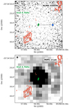 |
Fig. A.2. Panel A: continuum map of ALMA band 6 in grayscale with overplotted VLA C contours (the levels are 3σ, |
Data for MRC 0037−258 (z = 1.10).
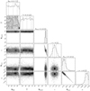 |
Fig. A.3. MRC 0037−258 Corner plot of the free parameters. |
A.2. MRC 0114−211
MRC 0114−211 has two detected continuum components in ALMA band 6. Both detections coincide with the two lower-frequency radio components (Fig. A.5). The SED fitting is done with five components, two synchrotron components (eastern and western radio components), two modified BB (one for each ALMA detection) and one AGN component. The western radio component (detected in VLA bands C and X) is assigned to the western ALMA detection and the same setup is also applied to the eastern radio and ALMA components. The VLA band X, ATCA 7 mm, and ALMA band 3 detections do not resolve the individual components and are only considered for fitting the total radio flux (the combination of the western and eastern synchrotron power-law components). The two ALMA band 6 points are both fitted with a combination of a synchrotron power-law and a modified BB. The PACS. SPIRE, MIPS and IRS data points are fitted to the combination of the two modified black bodies and a AGN component. The best fit model is where the brighter western component in ALMA band 6 is pure synchrotron and the eastern component is dominated by thermal emission (Fig. A.4). The PDF of the free parameters is shown in Fig. A.6, where it is clear that the free parameters, NBB, 1 and T1 of the first BB associated with the western ALMA detection are completely unconstrained.
A.3. TN J0121+1320
TN J0121+1320 has one continuum detection in the ALMA band 3 observations which coincides marginally with the compact radio component (Fig. A.8). SED fitting is done with three components, a single synchrotron power law, a modified BB, and an AGN component. The single component in radio VLA C and X bands is assigned to a synchrotron power-law, the ALMA detection is assigned to both a synchrotron and a modified BB model. The PACS, SPIRE, MIPS and IRS data points are fitted with a combination of the modified BB component and an AGN component. The best fit solution implies that the ALMA emission is due to thermal dust emssion but the AGN component is unconstrained as there are only upper limits in the mid-infrared. The PDF of the free parameters as shown in Fig. A.9, where it is clear that the AGN model is completely unconstrained.
 |
Fig. A.4. SED of MRC 0114−211. Black solid line shows best fit total model, green and purple dashed lines are the western and eastern synchrotron lobes, respectively. The black dash-dotted line is one blackbody component associated to one of the ALMA band 6 detections. Black dotted line indicates the AGN component. The colored points indicate data with sub-arcsec resolution and black ones indicate the data with low spatial resolution. Green pentagons indicate the western radio lobe, purple hexagons indicate the eastern radio lobe, the blue diamond indicates one of the ALMA band 6 detection, and the magenta square is the second ALMA detection. Filled black circles indicate detections (> 3σ) and downward pointing triangles the 3σ upper limits (Table A.2). |
Data for MRC 0114−211 (z = 1.41).
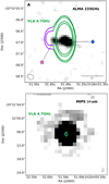 |
Fig. A.5. Panel A: continuum map of ALMA band 6 with VLA C contours overlaid (levels are as Fig. A.2; σ = 71 μJy). The blue and pink markers indicate the two different components detected with ALMA and correspond to the same data points as Fig. A.4. The purple and green contours show the two components of the VLA data and correspond to the markers of the same colors as in the SED fit. Panel B: MIPS 24 μm continuum map with VLA 4.7 GHz contours overlaid. We note that the scale of the MIPS image is five times larger than the image displayed in panel A. |
A.4. MRC 0152−209
MRC 0152−209 has two detected continuum components in the ALMA observations and both of which coincide with lower frequency radio detections (Fig. A.11). SED fitting is done with four components, one total synchrotron, two modified BB and one AGN component. The VLA data is fitted to one synchrotron power-law since it is not possible to resolve individual components in any of the observed bands. The two ALMA band 6 detections are fitted to the same total synchrotron power-law and two individual modified BB for each ALMA detection. The LABOCA, PACS, SPIRE, MIPS and IRS data points are all fitted with a combination of the two individual modified BB and an AGN component. The best fit model is one where both of the ALMA detections are dominated by dust emission. The radio slope is too steep to be able to account for the observed ALMA continuum. It is unclear wherever the northern or southern dust component corresponds to the host galaxy, but since the southern component (indicated by the blue BB line in Fig. A.10) is brighter, this component is more likely to be the host galaxy and the northern emission, is an interacting companion. Though this is not enough to determine which of the component host the radio-loud AGN. In Emonts et al. (2015a) they argue that the NW component is the host, which might be more correct. If this is the case, then the SFR would be one order of magnitude lower and the galaxy would be on the MS, instead of lying above the MS relation. Though the morphology of the source strongly suggest it is a merger, a SFR∼1000 M⊙ yr−1 is reasonable for a merging system. The PDF of the free parameters can be found in Fig. A.12.
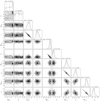 |
Fig. A.6. MRC 0114−211 Corner plot of the free parameters. |
 |
Fig. A.7. SED of TN J0121+1320. Black solid line shows the best fit total emission model, black dashed line represents the synchrotron emission and the black dash-dotted lines represents the black body emission. The colored data point indicate the data with sub-arcsec resolution and black ones indicated data of low spatial resolution. The blue diamond indicates the ALMA band 3 detection. Filled black circles indicate detections (> 3σ) and downward pointing triangles the 3σ upper limits (Table A.3). |
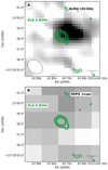 |
Fig. A.8. Panel A: continuum map of ALMA band 3 with overlaid VLA C contours (levels are as Fig. A.2, σ = 70 μJy). Panel B: MIPS 16 μm continuum map. |
Data for TN J0121+1320 (z = 3.516).
A.5. MRC 0156−252
MRC 0156−252 has two detected continuum detections, where one detection coincides with the radio core and the other with the northern radio lobe (Fig. A.13). SED fitting is done with five components, two synchrotron power-laws (one for the core, one for the northern lobe, the southern lobe is excluded from the fit), two modified BB for the two ALMA detections, and one AGN component. The VLA L and ATCA 7 mm bands are fitted to the total synchrotron emission since these data do not resolve the individual radio components, while the VLA C and X band fluxes are fitted with two individual synchrotron power-laws. The two ALMA band 6 flux points are fitted to a combination of the individual synchrotron power-law and modified black bodies. The LABOCA, PACS, SPIRE, MIPS and IRS data points are fitted by a combination of a modified BB and an AGN component. The best fit model is one where both the ALMA detections are dominated by synchrotron emission. This is because there are only upper limits in the FIR and they do not require the modified BB to be very bright (Fig. A.13). The PDF of the free parameters is shown in Fig. A.15, which clearly demonstrates that both BB models are completely unconstrained as expected given the upper limits in the FIR.
A.6. TN J0205+2242
TN J0205+2242 has no continuum detection (Fig. A.17). SED fitting with MR-MOOSE is done with five models, two synchrotron power-laws (northern and southern radio component), two modified BB and one AGN component. The northern radio component (detected in VLA bands C and X) is assigned to the northern ALMA upper limit and the same setup is also applied to the southern radio and ALMA upper limit. The VLA band X detection does not resolve the individual components and are only considered for fitting the total radio flux (the combination of the northern and southern synchrotron power-law components). The two ALMA band 3 upper limits are both fitted with a combination of a synchrotron power-law and a modified BB. The SCUBA, PACS, SPIRE and IRS data points are fitted to the combination of the two modified black bodies and a AGN component. The best fit only constrain the two synchrotron models, both the SF and AGN dust components are unconstrained, due to the fact that all FIR and MIR data points are upper limits (Fig. A.16). The PDF of the free parameters can be found in Fig. A.18, where it is clear that only the two synchrotron components are constrained.
 |
Fig. A.9. TN J0121+1320 Corner plot of the free parameters. |
A.7. MRC 0211−256
MRC 0211−256 has one single continuum detection, which does not coincide with the radio emission (Fig. A.20). SED fitting with MrMosse is done with three components, one synchrotron power-law, one modified BB and one AGN component. VLA L, X, and C bands are only considered for fitting the total radio flux since only the total integrated flux for band L and X, C are reported in Condon et al. (1998) and Kapahi et al. (1998). The ALMA detection is assigned to both the synchrotron power-law and a modified BB component. The LABOCA, SPIRE, PACS, MIPS and IRS data points are fitted to the combination of the modified BB and a AGN component. The best fit model gives a solution where the ALMA band 6 flux is dominated by thermal dust emission (Fig. A.19). The PDF of the free parameters can be found in Fig. A.21.
A.8. TXS 0211–122
TXS 0211−122 have one single continuum detection, which coincide with the radio core (Fig. A.23). SED fitting with MR-MOOSE is done with three components, one synchrotron power-law (for the radio core, the two lobes are excluded in the fit), one modified BB and one AGN component. The VLA data is fitted to the synchrotron component, the ALMA data point is assigned to both the synchrotron power-law and a modified BB. The LABOCA, PACS, SPIRE, MIPS and IRS are fitted to the combination of the modified BB and a AGN component. The best fit model gives a solution where the ALMA band 6 flux is dominated by emission from heated dust (Fig. A.22). The reason why the PACS 160 μm data point is not well fitted is due to the fact that the AGN power-law have a fixed exponential cut off at 33 μm rest frame and the ALMA point puts hard constraints on the normalization parameter of the modified BB. The PDF of the free parameters can be found in Fig. A.24.
A.9. MRC 0251−273
MRC 0251−273 has one continuum detection which coincides with one of the two radio components (Fig. A.26). SED fitting with MR-MOOSE is done with four components, two synchrotron (northern and southern radio component), one modified BB and one AGN component. The northern radio component (detected in VLA bands C and X) is assigned to the ALMA detection and fitted with with an individual power-law. The southern radio component is only assigned to the VLA bands C and X. The ALMA detection is associated to the northern synchrotron power-law and a modified BB. The SCUBA, SPIRE, PACS, MIPS and IRS data are fitted to the combination of the modified BB and a AGN component. The best fit model gives that the ALMA detection is dominated by dust emission (Fig. A.25). The slope of the northern synchrotron component is very steep and this can be due to not properly extracted photometry because of blending between the two components. The PDF of the free parameters can be found in Fig. A.27.
 |
Fig. A.10. SED of MRC 0152−209. Black solid line shows best fit total model, black dashed line represents the total synchrotron emission. The magenta and blue dashed-dotted line represent the two black bodies of the northern and southern ALMA 6 detections, respectively. Black dotted line indicates the AGN component. The colored data points indicate data with sub-arcsec resolution and black ones indicate data of lower spatial resolution. The magenta square and blue diamond indicates the ALMA band 6 detection of the northern and southern components, respectively. Filled black circles indicate detections (> 3σ) and downward pointing triangles the 3σ upper limits (Table A.4). |
Data for MRC 0152−209 (z = 1.92).
A.10. MRC 0324−228
MRC 0324−228 has no continuum detection with ALMA (Fig. A.29). SED fitting with MR-MOOSE is done with four components, two synchrotron power-law (northern and southern radio component), one modified BB and one AGN component. The northern radio component (detected in VLA bands C and X) is assigned to an individual synchrotron power-law and the same setup is also applied for the southern radio component. The VLA band L and ATCA 7 mm data do not resolve the individual components and are only considered for fitting the total radio flux (the combination of the northern and southern synchrotron power-law components). The ALMA band 6 detection is also assigned to the total radio flux and to a modified BB. The LABOCA, SIPRE, PACS, MIPS and IRS data are fitted to the combination of the modified BB and a AGN component. The best fit model does not constrain the modified BB due to only upper limits in the FIR. Without an intermediate data point between ALMA and ATCA 7 mm it is not possible to determine where the steepening occurs, but the upper limit in ALMA is consistent with a continued synchrotron slope. The PDF of the free parameters can be found in Fig. A.30.
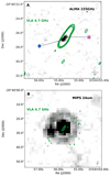 |
Fig. A.11. Panel A: continuum map of ALMA band 6 with overlaid VLA C contours (levels are as Fig. A.2, σ = 56 μJy). The blue and pink markers show the two ALMA detections and correspond the same markers used in Fig. A.10. Panel B: MIPS 24 μm continuum map and we note that the scale of the MIPS image is 5 times larger. |
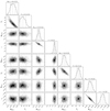 |
Fig. A.12. MRC 0152−209 Corner plot of the free parameters. |
A.11. MRC 0350–279
MRC 0350−279 has no continuum detection with ALMA (Fig. A.32). SED fitting with MR-MOOSE is done with four components two synchrotron power-law (northern and southern radio component), one modified BB and one AGN component. The northern radio component (detected in VLA bands C and X) is assigned to an individual synchrotron power-law and the same setup is also applied for the southern radio component. The VLA band L and ATCA 7 mm data do not resolve the individual components and are only considered for fitting the total radio flux (the combination of the northern and southern synchrotron power-law components) The ALMA band 6 upper limit is assigned to the total radio flux and a modified BB. The LABOCA, SIPRE, PACS, MIPS and IRS data are fitted to the combination of the modified BB and a AGN component. The best fit model gives a solution where the ALMA detection is dominated by synchrotron, but the combined models is slightly over predict the 3σ upper limit at 235 GHz (Fig. A.31). The PDF of the free parameters can be found in Fig. A.33.
 |
Fig. A.13. SED of MRC 0156−252. Black solid line shows the best fit total model, green and purple dashed line represents the northern lobe and synchrotron emission from the core, respectively. Black dotted line indicates the AGN component. The colored points are data which have sub-arcsec resolution and black ones indicate data of lower resolution. Green pentagons represent the fluxes of the radio core, purple hexagons are the fluxes of the northern radio lobe, the blue diamond indicates the ALMA band 6 detection which coincides with the radio core and the magenta square is the second ALMA detection of the northern radio lobe. Filled black circles indicate detections (> 3σ) and downward pointing triangles 3σ upper limits (Table A.5). |
Data for MRC 0156−252 (z = 2.02).
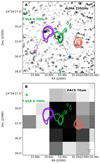 |
Fig. A.14. Panel A: continuum map of ALMA band 6 with overlaid VLA C contours (levels are as Fig. A.2, σ = 96 μJy). The blue and pink markers show the two ALMA detections and correspond to the same markers used for the SED in Fig A.13. The core and northern radio lobes are color coded in the same colors as the flux markers in Fig. A.10, the flux of the southern lobe (red radio contours) was not used in the SED fit. Panel B: PACS 70 μm continuum map with radio contours overlaid. |
A.12. MRC 0406–244
MRC 0406−244 has one single continuum detection which coincides with the radio core (Fig. A.35). SED fitting with MR-MOOSE is done with three components, one synchrotron (of the radio core, the two lobes are excluded in the fit), one modified BB and one AGN component. The VLA data is fitted to the synchrotron power-law, the ALMA detection is assigned to both the synchrotron component and a modified BB. The LABOCA, SPIRE, PACS, MIPS and IRS is fitted to combination of the modified BB and a AGN component. The best SED fits favors a solution where the ALMA detection is dominated by synchrotron emission, due to the many upper limits in FIR and that there is no intermediate data point which could conclude whether the synchrotron is steepening at higher frequencies. The modified BB is completely unconstrained (Fig. A.34). The PDF of the free parameters can be found in Fig. A.36.
A.13. PKS 0529–549
PKS 0529−549 has two continuum detections, both coinciding with the two radio components (Fig. A.38). The SED fit is done with five components, two synchrotron power-laws (eastern and western radio components), two modified BB and one AGN component. The western radio component (detected in ATCA 8640–18496 MHz) is assigned to the western ALMA detection and fitted with an individual synchrotron power-law and the same setup is also applied to the eastern radio and ALMA components. The ATCA 7 mm data do not resolve the individual components and are only considered for fitting the total radio flux (the combination of the western and eastern synchrotron power-law components). The eastern ALMA detection is assigned to the first synchrotron component and to a modified BB component, while the western ALMA detection is similarly assigned to the second synchrotron component and another modified BB component. The SPIRE, PACS, MIPS and IRS data are fitted to the combination of the two modified black bodies and an AGN component. The best solution finds that the western ALMA detection is dominated by thermal dust emission and the eastern component is pure synchrotron emission (Fig. A.37). The PDF of the parameters shows that the second BB is completely unconstrained (Fig. A.39).
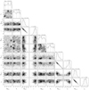 |
Fig. A.15. MRC 0156−252 Corner plot of the free parameters. |
A.14. TN J0924–2201
TN J0924−2201 has one single continuum detection which coincides with the eastern radio component (Fig. A.41). SED fitting with MR-MOOSE is done with four components, two synchrotron power laws (eastern and western radio component), one modified BB and one AGN component.
The western radio component (detected in VLA bands U and K) is assigned to the ALMA detection and fitted with an individual synchrotron power-law. The eastern radio component (detected in VLA bands U and K) is only fitted with a synchrotron power-law Sync, 2). The VLA bands C and L do not resolve the individual components and are only considered for fitting the total radio flux (the combination of the western and eastern synchrotron power-law components). The western ALMA detection is assigned to the western synchrotron component (Sync, 1), and to a modified BB component. The SCUBA, SPIRE, PACS, MIPS and IRS data is fitted to the combination of the modified BB and a AGN component. The SED fit only constrain the synchrotron models and the modified BB and AGN are unconstrained. This is due to the fact that there is only one detection in the FIR and it is not possible to constrain the modified BB with two free parameters to only one data point. The solution for the two radio lobes shows that the ALMA detection is likely completely dominated by thermal dust emission. The plotted modified BB in Fig. A.40 is scaled to the ALMA detection with slope and temperature fixed to β = 2.5 and T=50, like in the case where the upper-limit of the  is calculated for the sources with ALMA non-detections. The PDF of the free parameters can be found in Fig. A.42, which shows that both the BB and AGN is unconstrained.
 |
Fig. A.16. SED of TN J0205+2242. Black solid line shows best fit total model, green and purple dashed line is the north and south synchrotron, respectively. The colored data points are sub-arcsec resolution data and black ones indicated data of low resolution. The blue and purple downward pointing triangles indicates the ALMA band 3 upper limits at the location of the two radio lobes, where the blue triangle is the upper limit of the host galaxy and the north synchrotron component. Filled black circles indicate detections (> 3σ) and downward pointing triangles the 3σ upper limits (Table A.6). |
Data for TN J0205+2242 (z = 3.506).
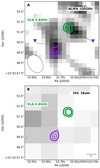 |
Fig. A.17. Panel A: continuum map of ALMA band 3, overlaid VLA C contours (levels are as Fig. A.2, σ = 85 μJy). Blue and purple markers indicate the two different upper limits with ALMA and correspond to the same data points as Fig. A.16. The green and purple show the two components of the VLA data and correspond to the markers of the same colors as in the SED fit. Panel B: IRS 16 μm continuum map. |
A.15. MRC 0943–242
MRC 0943−242 has several continuum detections with ALMA band 6, one at the host galaxy and three resolved companions (Fig. A.44). With ALMA band 4 the three companions are also detected, as well as two additional continuum components which coincide with the two radio components seen with VLA. SED fitting with MR-MOOSE is done with five models, two synchrotron power-laws (north and south component), two modified BB (one for the host and one for the three companions grouped together) and one AGN component. The VLA X, C and ALMA band 4 resolve the synchrotron components and the two radio lobes are fitted with two individual power-laws. The VLA L, ATCA 3 mm and 7 mm do not resolve any individual components and are assigned to the combination of both synchrotron models. The LABOCA, SPIRE, PACS, MIPS and IRS data are assigned to both the modified BB of the host and companions as well as the AGN component. The best fit model, shows that ALMA detection at the host galaxy is dominated by thermal dust emission, and the three companions are also consistent with emission from heated dust. The two synchrotron components are consistent with a power-law from radio to ALMA band 4 (Fig. A.43). One reason why the PACS 100 μm is not well fitted is because either the temperature of the modified BB must be higher which is outside the parameter space or because the fixed νcut does not allow the AGN component to account fully for the observed flux. The PDF of the free parameters can be found in Fig. A.45.
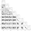 |
Fig. A.18. TN J0205+2242 Corner plot of the free parameters. |
A.16. TN J2007–1316
TN J2007−1316 has no ALMA continuum detection (Fig. A.56). SED fitting with MR-MOOSE is done with four components, two synchrotron (northern and southern radio component), one modified BB and one AGN component. The northern and southern radio components (detected in VLA bands C and X) are each assigned to an individual synchrotron power-law. The VLA L band do not resolve individual components and is only considered for fitting the total radio flux (the combination of the north and south synchrotron power-law). The ALMA upper limit at the AGN host location is assigned to both synchrotron components and the modified BB. The SPIRE, PACS, MIPS and IRS data a fitted to the combination of the modified BB and a AGN component. The best fit model only constrains the synchrotron and AGN components, while the modified BB remains unconstrained because there are only upper limits in the FIR (Fig. A.55). The PDF of the free parameters can be found in Fig. A.57, which shows that the BB is completely unconstrained.
 |
Fig. A.19. SED of MRC 0211−256. Black solid line shows best fit total model, dashed line is total synchrotron, dash-dotted line is the blackbody component and the dotted line indicates the AGN component. The colored data point is sub-arcsec resolution data and black ones indicated data of low resolution. Blue diamond indicates ALMA band 6 detection. Filled black circles indicate detections (> 3σ) and downward pointing triangles the 3σ upper limits (Table A.7). |
Data for MRC 0211−256 (z = 1.3).
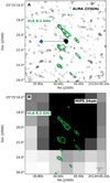 |
Fig. A.20. Panel A: continuum map of ALMA band 6 with overlaid VLA C contours (levels are as Fig. A.2, σ = 86 μJy). The blue diamond indicates the ALMA detection and is the same marker used in Fig. A.19. The green contours show the portion of the VLA data that is used in the SED fit. Panel B: MIPS 24 μm continuum map. |
A.17. MRC 1017–220
MRC 1017−220 has one single continuum detection with ALMA, which coincides with the unresolved synchrotron component (Fig. A.47). SED fitting with MR-MOOSE is done with three components, one synchrotron, one modified BB and one AGN component. The VLA L, C, X and ATCA 7 mm bands are assigned to the synchrotron component and the ALMA detection is assigned to both the synchrotron power-law and a modified BB. The LABOCA SPIRE, PACS, MIPS and IRS points are assigned to the combination of the modified BB and an AGN component. The best fit solution gives a dominating synchrotron contribution to the ALMA detection (Fig. A.46), due to the many upper limit in the FIR. But studying the SED it seems likely that the synchrotron is turning over at high frequencies but without a data point at an intermediate frequency between the radio and ALMA data, it is not possible to make a final conclusion whether the ALMA detection is synchrotron dominated or not. The PDF of the free parameters can be found in Fig. A.48, which shows that the modified BB is unconstrained.
A.18. 4C 03.24
4C 03.24 two continuum detections in ALMA band 3, one that coincides with the north synchrotron lobe and one that covers both the radio core and hot spot of the south lobe (Fig. A.50). The SED fitting with MR-MOOSE is done with six components, three synchrotron (core, northern and southern radio component), two modified BB (northern and southern) and one AGN component. The VLA L detection does not resolve the individual components and are only considered for fitting the total radio flux (the combination of the western, eastern and core synchrotron power-law components). The C and X bands resolves the three components are there assigned to individual synchrotron models. The northern ALMA detection is assigned to the northern synchrotron power-law and one modified BB and the southern ALMA detection is assigned to a combination of the southern and core synchrotron components, as well as a modified BB. The SCUBA, SPIRE, PACS, MIPS and IRS are fitted to the combination of the two modified BB and a AGN component. The best fit model finds that the north ALMA detection is dominated by thermal dust emission and the southern ALMA detection is dominated by synchrotron emission from the south radio lobe. The PDF of the free parameters can be found in Fig. A.51.
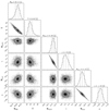 |
Fig. A.21. MRC 0211−256 Corner plot of the free parameters. |
A.19. TN J1338–1942
TN J1338−1942 has one coninuum detection with ALMA, which coincides with the northern radio component (Fig. A.53). SED fitting with MR-MOOSE is done with four components, two synchrotron (northern and southern radio component), one modified BB and one AGN component. The northern radio component (detected in VLA bands C and X) is assigned to the northern ALMA detection and fitted with an individual synchrotron power-law. The southern radio component (detected in VLA bands C and X) is also fitted with an individual power-law and assigned to the southern ALMA upper limit. The VLA L data do not resolve the individual components and are only considered for fitting the total radio flux (the combination of the northern and southern synchrotron power-law components). The northern ALMA detection is assigned to the norther synchrotron component and to a modified BB component. The MAMBO SCUBA, SPIRE, PACS, MIPS and IRS are fitted to the combination of the modified BB and a AGN component. The best fit is where the ALMA flux is a combination of the northern synchrotron lobe and dust emission. The PDF of the free parameters can be found in Fig. A.54.
A.20. MRC 2025–218
MRC 2025–218 has no detection continuum detection (Fig. A.59, neither the host nor the synchrotron are detected. SED fitting with MR-MOOSE is done with four components, two synchrotron (north and south radio component), one modified BB and one AGN component. The north radio component (detected in VLA bands C and X) is assigned to an individual synchrotron power-law, the same set up is used for the southern radio component. The VLA L and ATCA 7 mm to does not resolve any individual components and are only considered for fitting the total synchrotron power-law (the combination of the north and south power-laws). The ALMA upper limit at the AGN host location is associated to both synchrotron components and the modified BB. The LABOCA, SPIRE, PACS, MIPS and IRS data are fitted to combination of the modified BB and a AGN component. The best fit model only constrains the synchrotron and AGN parts, the modified BB are unconstrained because there are only upper limits in the FIR, see Fig. A.58. The PDF of the free parameters can be found in Fig. A.60, which shows that the BB is unconstrained.
 |
Fig. A.22. SED of TXS 0211–122. Black solid line shows best fit total model, green dashed line is total synchrotron, black dash-dotted line is the blackbody component, black dotted line indicates the AGN component. The colored data points are sub-arcsec resolution data and black ones indicate data of low resolution. Green pentagons are the radio core and the blue diamond indicates ALMA band 6 detection. Filled black circles indicate detections (> 3σ) and downward pointing triangles the 3σ upper limits (Table A.8). The open diamond shows available ATCA data but only plotted as a reference and was not used in the SED fit. |
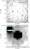 |
Fig. A.23. Panel A: continuum map of ALMA band 6 with overlaid VLA C contours (levels are as Fig. A.2, σ = 53 μJy). The blue diamond indicates the ALMA detection and is the same marker used in Fig. A.22. The green contours show the portion of the VLA data that is used in the SED fit, the red contours are excluded in the fit. Panel B: MIPS 24 μm continuum map. |
Data for TXS 0211−122 (z = 2.34).
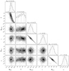 |
Fig. A.24. TXS 0211–122 Corner plot of the free parameters. |
A.21. MRC 2048–272
MRC 2048−272 has no continuum detection with ALMA (Fig. A.62). SED fitting with MR-MOOSE is done with four components, two synchrotron (north and south radio component), one modified BB and one AGN component. The northern and southern radio component (detected in VLA bands C and X) are each assigned to an individual synchrotron power-law. The VLA L and ATCA 7 mm bands do not resolve any individual components and are only considered for fitting the total radio flux (the combination of the northern and southern synchrotron power-law components). The ALMA upper limit at the AGN host location is associated to both synchrotron components and the modified BB. The LABOCA, SPIRE, PACS, MIPS and IRS data are fitted to the combination of the modified BB and AGN component. The best fit model only constrains the synchrotron, and both the AGN the modified BB models are unconstrained because the FIR through mid-infrared data are only upper limits. The PDF of the free parameters can be found in Fig. A.63, which shows that both the BB and AGN is unconstrained.
A.22. MRC 2104–242
MRC 2104−242 has no continuum detection with ALMA (Fig. A.65). SED fitting with MR-MOOSE is done with three components, one synchrotron (only the core, the northern and southern radio components are excluded in the fit), one modified BB and one AGN component. The VLA C and X band data are assigned to the sychrotron power law of the radio core. The ALMA upper limit at the AGN host location is associated to both synchrotron components and the modified BB. The SPIRE, PACS, MIPS and IRS data are fitted to the combination of the modified BB and a AGN component. The best fit model only constrains the synchrotron and AGN component, the modified BB models are unconstrained due to the FIR data consisting only of upper limits (Fig. A.64). The PDF of the free parameters can be found in Fig. A.66, which shows that the BB is unconstrained.
A.23. 4C 23.56
4C 23.56 has no continuum detection in ALMA band 6, but is detected in band 3. The detection coincides with the radio core (Fig. A.68). SED fitting with MR-MOOSE is done with three components, one synchrotron power-law (of the core, the north and south lobe are excluded for the fit), one modified BB and one AGN component. The VLA C and X band fluxes are assigned to the synchrotron power-law. The ALMA band 3 detection is assigned to both the synchrotron model and modified BB and the same set up is used for the ALMA band 6 upper limit. The LABOCA, SPIRE, PACS, MIPS and IRS are assigned to the combination of the modified BB and a AGN component. The best fit model constrains the synchrotron and gives that the ALMA band 3 detection is dominated by synchrotron emission. The modified BB is unconstrained (Fig. A.67) due to the fact that all the FIR data points are upper limits. This source has a low SFR and the IR emission is dominated by the AGN. 4C 23.56 was use to fix the νcut=33 μm for the model describing the AGN heated dust, because the SF contribution in the FIR is very weak. The PDF of the free parameters can be found in Fig. A.69, which shows that the BB is unconstrained.
 |
Fig. A.25. SED of MRC 0251−273. Black solid line shows best fit total model, green and purple dashed line is north and south synchrotron lobes, respectively. Black dashed-dotted line shows the blackbody and the black dotted line indicates the AGN component. The colored data points are sub-arcsec resolution data and black ones indicate data of low resolution. Green pentagons are north synchrotron, purple hexagons are the south radio component and the blue diamond indicates the ALMA band 6 detection. Filled black circles indicate detections (> 3σ) and downward pointing triangles the 3σ upper limits (Table A.9). |
Data for MRC 0251−273 (z = 3.16).
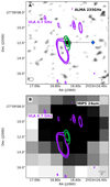 |
Fig. A.26. Panel A: continuum map of ALMA band 6 with overlaid VLA C contours (levels are as Fig. A.2, σ = 48 μJy). The blue diamond indicates the ALMA detection and is the same marker style used in Fig. A.25. Green contours show the two components of the VLA data and correspond to the markers of the same colors as in the SED fit. Panel B: MIPS. Panel B: MIPS 24 μm continuum map |
A.24. 4C 19.71
4C 19.71 has three detected continuum components in ALMA band 3, one coincides with the AGN host galaxy and two coincide with the northern and southern synchrotron lobes (Fig. A.71). SED fitting with MR-MOOSE is done with four components, two synchrotron (northern and southern radio components), one modified BB and one AGN component. The northern radio component (detected in VLA bands C and X) is assigned to the northern ALMA detection and fitted to a individual synchrtoron component, the same setup is also applied to the southern radio and ALMA components. The VLA L detection does not resolve any individual components and are only considered for fitting the total radio flux (the combination of the northern and southern synchrtorn power-laws). The ALMA detection at the host location is assigned to only the modified BB and the SCUBA, SPIRE, PACS, MIPS and IRS are fitted to the combination of the modified BB and a AGN component. The best fit model constrains the two synchrotron components and they are fitted out to ALMA band 3. The ALMA detection at the host is dominated by thermal dust emission. The PDF of the free parameters can be found in Fig. A.72.
A.25. MRC 2224–273
MRC 2224−273 has a single continuum detection which coincides with the compact synchrotron emission (Fig. A.74). SED fitting with MR-MOOSE is done with three components, one synchrotron power-law, one modified BB and one AGN component. The VLA X, C and L data are assigned to the synchrotron power-law, the ALMA detection is assigned to both synchrotron component and a modified BB. The LABOCA, SPIRE, PACS, MIPS and IRS are fitted to the combination of the modified BB and a AGN component. The best fit model gives that the ALMA detection is dominated by thermal dust emission. Without a flux at intermediate radio frequencies between the VLA and ALMA data, it is not possible to constrain whether or not the synchrotron is steeping. In any case, the synchroton emission does not significantly contribute to the emission detected by ALMA. The PDF of the free parameters can be found in Fig. A.75.
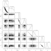 |
Fig. A.27. MRC 0251−273 Corner plot of the free parameters. |
 |
Fig. A.28. SED of MRC 0324−228. Black solid line shows best fit total model, green and purple dashed line is north and south synchrotron lobes, respectively. Black dotted line indicates the AGN component. The colored data points are sub-arcsec resolution data and black ones indicate data of low resolution. Green pentagons are north synchrotron, purple hexagons are the south radio component and the blue triangle indicates the ALMA band 6 3σ upper limit. Filled black circles indicate detections (> 3σ) and downward pointing triangles the 3σ upper limits (Table A.10). |
Data for MRC 0324−228 (z = 1.89).
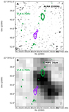 |
Fig. A.29. Panel A: continuum map of ALMA band 6 with overlaid VLA C (levels are as Fig. A.2, σ = 53 μJy). The green and purple contours show the two components of the VLA data and correspond to the markers of the same colors as in the SED fit (Fig. A.28). Panel B: MIPS 24 μm continuum map. |
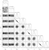 |
Fig. A.30. MRC 0324–228 Corner plot of the free parameters. |
 |
Fig. A.31. SED of MRC 0350–279. Black solid line shows best fit total model, green and purple dashed line are the north and south synchrotron lobes, respectively. Black dotted line indicates the AGN component. The colored data points are sub-arcsec resolution data and black ones indicate data of low resolution. Green pentagons and purple hexagons are the north and south radio component, respectively and the blue triangle indicates the ALMA band 6 3σ upper limit. Filled black circles indicate detections (> 3σ) and downward pointing triangles the 3σ upper limits (Table A.11). |
Data for MRC 0350−279 (z = 1.90).
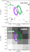 |
Fig. A.32. Panel A: continuum map of ALMA band 6 with overlaid VLA C contours (levels are as Fig. A.2,σ = 58 μJy). The purple and green contours show the two components of the VLA data and correspond to the markers of the same colors as in the SED fit. Panel B: MIPS 24 μm continuum map. |
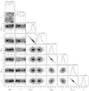 |
Fig. A.33. MRC 0350−279 Corner plot of the free parameters. |
 |
Fig. A.34. SED of MRC 0406–244. Black solid line shows best fit total model, green dashed line is the synchrotron core and the black dotted line indicates the AGN component. The colored data points are sub-arcsec resolution data and black ones indicate data of low resolution. Green pentagons are the radio core and the blue diamond indicates the ALMA band 6 detection. Filled black circles indicate detections (> 3σ) and downward pointing triangles the 3σ upper limits (Table A.12). The open diamond indicate available ATCA data but only plotted as a reference and was not used in the SED fit. |
Data for MRC 0406−244 (z = 2.43).
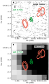 |
Fig. A.35. Panel A: continuum map of ALMA band 6 with overlaid VLA C contours (levels are as Fig. A.2, σ = 92 μJy). The green contours show the portion of the VLA data that is used in the SED fit, the red contours are excluded in the fit. Panel B: MIPS 24 μm continuum map. |
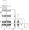 |
Fig. A.36. MRC 0406–244 Corner plot of the free parameters. |
 |
Fig. A.37. SED of PKS 0529–549. The black solid line shows best fit summed model, green and purple dashed lines are eastern and western synchrotron lobes, respectively. Blue dashed-dotted line shows the scaled BB assigned to the west ALMA detection. The colored data points indicate data with sub-arcsec resolution and black ones indicate data with lower resolution. Green pentagons indicate the location of the eastern synchrotron emission, purple hexagons represent the western radio component, the blue diamond and pink square represents the west and east ALMA detection, respectively. Filled black circles indicate detections (> 3σ) and downward pointing triangles the 3σ upper limits (Table A.13). |
Data for PKS 0529−549 (z = 2.58).
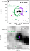 |
Fig. A.38. Panel A: continuum map of ALMA band 6 with overlaid ATCA 16.4 GHz contours (levels are as Fig. A.2, σ = 55 μJy). The blue and pink markers indicate the two ALMA detections and correspond to the same marker used in the SED (Fig. A.37). The green and purple contours show the two components of the VLA data and correspond to the markers of the same color as in the SED fit. Panel B: MIPS 24 μm continuum map, observe that the scale of the MIPS image is 5 times larger than panel A. |
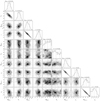 |
Fig. A.39. PKS 0529–549 Corner plot of the free parameters. |
 |
Fig. A.40. SED of TN J0924–2201. Black solid line shows best fit total model, black dashed line is the total synchrotron, the black dash-dotted lines is the blackbody and the black dotted line indicates the AGN component. The colored data points are sub-arcsec resolution data and black ones indicate data of low resolution. The blue diamond indicates the ALMA band 3 detection. Filled black circles indicate detections (> 3σ) and downward pointing triangles the 3σ upper limits (Table A.14). |
Data for TN J0924−2201 (z = 5.195).
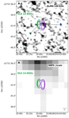 |
Fig. A.41. Panel A: continuum map of ALMA band 3 with overlaid VLA U contours (levels are as Fig. A.2, σ = 85 μJy). The blue marker indicates the ALMA detection and correspond to the same marker in the SED (Fig. A.40). The green and purple contours show the two components of the VLA data and corresponds to the markers if the same color as in the SED. Panel B: MIPS 24 μm continuum map. |
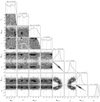 |
Fig. A.42. TN J0924–2201 Corner plot of the free parameters. |
 |
Fig. A.43. SED of MRC 0943–242. Black solid line shows best fit total model, green and purple dashed line is north and south synchrotron lobes, respectively. Black dashed-dotted line shows the blackbody fitted associated to one of the ALMA detections and the black dotted line indicates the AGN component. The colored data points are sub-arcsec resolution data and black ones indicate data of low resolution. Green pentagons are north synchrotron, purple hexagons are the south radio component, the blue diamond shows the ALMA 6 host detection and magenta squares indicates the total ALMA 4 and 6 flux of the 3 companions. Filled black circles indicate detections (> 3σ) and downward pointing triangles the 3σ upper limits (Table A.15). |
Data for MRC 0943–242 (z = 2.933).
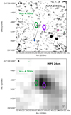 |
Fig. A.44. Panel A: continuum map of ALMA band 6 (cycle 1 and 2) with overlaid VLA C contours (levels are as Fig. A.2, σ = 75 μJy). Blue and pink markers indicate the two different components detected with ALMA detections and corresponds to the same data points in the SED fit. The green and purple contours show the two components if the VLA data and corresponds to the markers of the same colors as in the SED fit. Panel B: MIPS 24 μm continuum map. |
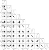 |
Fig. A.45. MRC 0943–242 Corner plot of the free parameters. |
 |
Fig. A.46. SED of MRC 1017–220. Black solid line shows best fit total model, black dashed line is the total synchrotron and the black dotted line indicates the AGN component. The colored data point is sub-arcsec resolution data and black ones indicate data of low resolution. The blue diamond indicates the ALMA band 6 detection. Filled black circles indicate detections (> 3σ) and downward pointing triangles the 3σ upper limits (Table A.16). |
Data for MRC 1017−220 (z = 1.77).
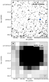 |
Fig. A.47. Panel A: continuum map of ALMA band 6, VLA maps not accessible, but the source is unresolved as shown in Pentericci et al. (2000). The blue diamond indicate the ALMA component and correspond to the same data point as Fig. A.46. Panel B: MIPS 24 μm continuum map |
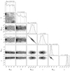 |
Fig. A.48. MRC 1017–220 Corner plot of the free parameters. |
 |
Fig. A.49. SED of 4C 03.24. Black solid line shows best fit total model, pink, green and purple dashed line is the north, core and south synchrotron component, respectively, the black dash-dotted lines is the blackbody and the black dotted line indicates the AGN component. The colored data points are sub-arcsec resolution data and black ones indicate data of low resolution. Green pentagons are the north synchrotron lobe, purple hexagrams are the radio core and the pink stars corresponds to the southern lobe. The blue diamond indicates the ALMA band 3 detection spatially coincident with the host galaxy, radio core and southern hotspot. Filled black circles indicate detections (> 3σ) and downward pointing triangles the 3σ upper limits (Table A.17). |
Data for 4C 03.24 (z = 3.57).
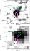 |
Fig. A.50. Panel A: continuum map of ALMA band 3 with overlaid VLA C contours (levels as Fig. A.2, σ = 50 μJy). The blue and green markers indicate the two different ALMA detections and correspond to the same data points as Fig. A.49. The green, purple and pink contours show the three components of the VLA data and correspond to the markers of the same colors as in the SED fit. Panel B: MIPS 24 μm continuum map. |
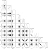 |
Fig. A.51. 4C 03.24 Corner plot of the free parameters. |
 |
Fig. A.52. SED of TN J1338–1942. Black solid line shows best fit total model, green and purple dashed line is the north and south synchrotron component, respectively. The black dash-dotted lines represents the blackbody and the black dotted line indicates the AGN component. The colored data points are sub-arcsec resolution data and black ones indicate data with low spatial resolution. The green hexagons and purple pentagons are radio data of the northern and southern synchrotron component, respectively. The blue diamond indicates the ALMA band 3 detection. Filled black circles indicate detections (> 3σ) and downward pointing triangles the 3σ upper limits (Table A.18). |
Data for TN J1338−1942 (z = 4.110).
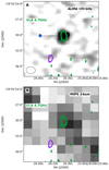 |
Fig. A.53. Panel A: continuum map of ALMA band 3 with plotted VLA C contours (levels are as Fig. A.2, σ = 55 μJy) The blue diamond indicates the ALMA detection and is the same marker used in Fig. A.52. The green and purple contours show the north and south radio component with the same color coding as in the SED plot. Panel B: MIPS 24 μm continuum map. |
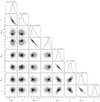 |
Fig. A.54. TN J1338–1942 Corner plot of the free parameters. |
 |
Fig. A.55. SED of TN J2007–1316. Black solid line shows best fit total model, green and purple dashed line are northern and southern synchrotron lobes, respectively. The black dotted line represents the AGN component. The colored data points indicate sub-arcsec resolution data and black ones indicate data with low spatial resolution. Green pentagons are northern synchrotron emission, purple hexagons are from the southern radio component and the blue triangle indicates the ALMA 4 3σ upper limit. Filled black circles indicate detections (> 3σ) and downward pointing triangles the 3σ upper limits (Table A.19). |
Data for TN J2007−1316 (z = 3.840).
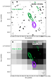 |
Fig. A.56. Panel A: continuum map of ALMA band 4 with overlaid VLA C contours (levels are as Fig. A.2, σ = 12 μJy). The green and purple contours show the two components of the VLA data and corresponds to the markers of the same colors as in the SED fit. Panel B: MIPS 24 μm continuum map. |
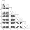 |
Fig. A.57. TN J2007–1316 Corner plot of the free parameters. |
 |
Fig. A.58. SED of MRC 2025–218. Black solid line shows best fit total model, green and purple dashed lines are northern and southern synchrotron lobes, respectively and the black dotted line indicates the AGN component. The colored data points are sub-arcsec resolution data and black ones indicate data with low spatial resolution. Green pentagons are for the northern radio component, purple hexagons are for the southern radio component, and the blue triangle indicates the ALMA 6 3σ upper limit. Filled black circles indicate detections (> 3σ) and downward pointing triangles the 3σ upper limits (Table A.20). |
Data for MRC 2025−218 (z = 2.630).
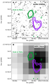 |
Fig. A.59. Panel A: continuum map of ALMA band 6, plotted VLA C contours (levels are as Fig. A.2, σ = 57 μJy). The green and purple contours show the two components of the VLA data and correspond to the makers of the same colors as in the SED fit. Panel B: MIPS 24 μm continuum map. |
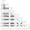 |
Fig. A.60. MRC 2025–218 Corner plot of the free parameters. |
 |
Fig. A.61. SED of MRC 2048–272. The black solid line shows the best fit total model, green and purple dashed lines are the northern and southern synchrotron lobes. Neither the blackbody nor the AGN component are fitted to the upper limits. The colored data points are sub-arcsec resolution data and black ones indicate data of low spatial resolution. Green pentagons are northern synchrotron, purple hexagons are the southern synchrotron component and the blue triangle shows the ALMA 6 3σ upper limit. Filled black circles indicate detections (> 3σ) and downward pointing triangles the 3σ upper limits (Table A.21). |
Data for MRC 2048−272 (z = 2.060).
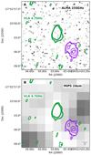 |
Fig. A.62. Panel A: continuum map of ALMA band 6 with overlaid VLA C contours (levels as Fig. A.2, σ = 53 μJy). The green and purple contours show the two components of the VLA data and corresponds to the markers of the same colors as in the SED fit. Panel B: MIPS 24 μm continuum map. |
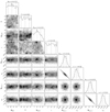 |
Fig. A.63. MRC 2048–272 Corner plot of the free parameters. |
 |
Fig. A.64. SED of MRC 2104–242. Black solid line shows best fit total model, green dashed line is the radio core and the black dotted line is the AGN component. The colored data points are sub-arcsec resolution data and black ones indicate data of low resolution. Green pentagons represent the synchrotron core and the blue triangle indicates the ALMA 6 3σ upper limit. Filled black circles indicate detections (> 3σ) and downward pointing triangles the 3σ upper limits (Table A.22). The open diamond indicates available ATCA data but is only plotted as a reference and not used in the SED fit. |
Data for MRC 2104−242 (z = 2.491).
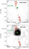 |
Fig. A.65. Panel A: continuum map of ALMA band 6 with overlaid VLA C contours (levels are as Fig. A.2, σ = 22 μJy). The green contours show the two components of the VLA data and correspond to the markers of the same colors as in the SED fit (Fig. A.64). The red contours are excluded in the fit. Panel B: MIPS 24 μm continuum map. |
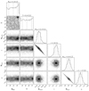 |
Fig. A.66. MRC 2104–242 Corner plot of the free parameters. |
 |
Fig. A.67. SED of 4C 23.56. Black solid line shows best fit total model, green dashed line is synchrotron power law for the radio core, dotted line indicates the AGN component. The colored data points are sub-arcsec resolution data and black ones indicate data with low spatial resolution. Green pentagons are emission from the radio core, cyan diamond from ALMA band 3, blue triangle indicates the ALMA band 3 3σ upper limit. Filled black circles indicate detections (> 3σ), downward pointing triangles the 3σ upper limits (Table A.1). |
Data for 4C 23.56 (z = 2.483).
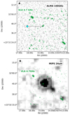 |
Fig. A.68. Panel A: continuum map of ALMA band 3 with overlaid VLA C contours (levels are as Fig. A.2, σ = 67 μJy). The cyan marker indicate the ALMA detection and corresponds to the marker use in the SED fit (Fig. A.67). The green contours show the portion of the VLA data that is used in the SED fit, the red contours are excluded in the fit. Panel B: MIPS 24 μm continuum map. |
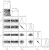 |
Fig. A.69. 4C 23.56 Corner plot of the free parameters. |
 |
Fig. A.70. SED of 4C 19.71. Black solid line shows best fit total model, black dashed line is the total synchrotron, the black dash-dotted lines is the blackbody and the black dotted line indicates the AGN component. The colored data points are sub-arcsec resolution data and black ones indicate data of low resolution. The blue diamond indicates the ALMA band 3 detection. Filled black circles indicate detections (> 3σ) and downward pointing triangles the 3σ upper limits (Table A.24). |
Data for 4C 19.71 (z = 3.592).
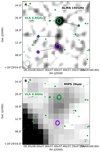 |
Fig. A.71. Panel A: continuum map of ALMA band 3 with overlaid VLA C contours (levels are as Fig. A.2, σ = 45 μJy). The blue, green and purple markers indicate the three different components detected with ALMA and correspond to the same data point as Fig. A.70. The green and purple contours show the two components of the VLA data and correspond to the markers of the same colors as in the SED fit. Panel B: MIPS 24 μm continuum map. |
 |
Fig. A.72. 4C 19.71 Corner plot of the free parameters. |
 |
Fig. A.73. SED of MRC 2224–273. Black solid line shows best fit total model, black dashed line is the total synchrotron, the black dash-dotted lines is the blackbody and the black dotted line indicates the AGN component. The colored data points are sub-arcsec resolution data and black ones indicate data of low resolution. The blue diamond indicates the ALMA band 6 detection. Filled black circles indicate detections (> 3σ) and downward pointing triangles the 3σ upper limits (Table A.25). |
Data for MRC 2224−273 (z = 1.68).
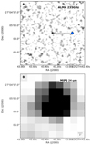 |
Fig. A.74. Panel A: continuum map of ALMA band 6. The blue marker indicates the ALMA dectection and corresponds to same data point in Fig. A.73. VLA maps not accessible, but the source is unresolved, as shown in Pentericci et al. (2000). Panel B: MIPS 24 μm continuum map. |
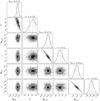 |
Fig. A.75. MRC 2224–273 Corner plot of the free parameters. |
All Tables
Average ratio of IR luminosities of this paper (denoted as  ) and those from Drouart et al. (2014, denoted as
  ).
).
All Figures
 |
Fig. 1. Best fit of the SED of 4C 23.56 when assuming that the AGN is solely responsible for the mid-infrared emission and allowing λcut to be an additional free parameter. The black solid line shows the best fit with |
| In the text | |
 |
Fig. 2. Comparison between the integrated IR AGN and SF luminosities computed in this paper compared to the results of Drouart et al. (2014). Top panel: comparison between the infrared luminosity of the AGN; bottom panel: comparison between the infrared luminosity of the starburst or star forming component. In both panels, the dashed line is the one-to-one relationship between luminosities. |
| In the text | |
 |
Fig. 3. Model comparison between the SF and AGN models of this paper and Drouart et al. (2014) for galaxies MRC 0350−279 (top left panel), MRC 0251−273 (top right panel), MRC 0156−252 (bottom left panel) and MRC 0211−256 (bottom right panel). In each plot, the black solid lines represent the synchrotron emission, dotted lines indicate the FIR thermal emission due to star-formation, and dash-dotted indicates the best-fit MIR emission due to the AGN as determined from the best fits to the photometry for each galaxy. The red lines with the same styles represent the same components as fitted in Drouart et al. (2014) A synchrotron power-law was not fit in the analysis of Drouart et al. (2014) |
| In the text | |
 |
Fig. 4. Estimated AGN luminosity, |
| In the text | |
 |
Fig. 5. Relationship between the SFR and stellar mass for different redshift bins. The colored shaded regions shows the MS of Santini et al. (2017) for each respective redshift bins with a 0.3 dex scatter around the MS. The gray shaded regions shows the MS with a 0.3 dex scatter from Schreiber et al. (2015), with a turnover at higher stellar masses. Our stellar masses have been scaled from a Kroupa to a Salpeter IMF to be consistent with the IMF used to make the MS in this comparison. In the highest redshift bin, 3 < z < 4, two sources, TN J1338+1942 and TNJ0924−2201, have been added to the right most panel despite having redshifts outside of the range used to construct the MS (z = 4.110 and 5.195 respectively). Given the redshift dependence on the normalization of the MS, these galaxies may lie relatively lower in comparison with the mean relation of a MS derived using galaxies over a more appropriate, higher redshift range (see Fig. 6). |
| In the text | |
 |
Fig. 6. Specific star formation rate, sSFR (Gyr−1), as a function of redshift. The black filled circles, black arrows and purple arrows represent the radio galaxies of our sample that are detected, detected but with unconstrained SF component and undetected with ALMA, respectively. The diamonds indicate sources which have both upper limits on the stellar mass and the SFR. The shaded region shows the galaxy main sequence (adapted from Schreiber et al. 2015) for M* = 1011.33 M⊙. We only indicate the redshift range 0.5 < z < 4 in the shaded region as z = 4 is the redshift limit of the objects studied in (Schreiber et al. 2015). We do not extrapolate to higher redshifts (Stark et al. 2013). |
| In the text | |
 |
Fig. 7. Comparison of our results in the LSF − LAGN plane to other studies. |
| In the text | |
 |
Fig. 8. Star formation rate, SFR in M⊙ yr−1, versus the projected physical size of the radio emission in kpc, calculated using the largest angular size (LAS) of the radio emission at 1.4 GHz (De Breuck et al. 2010). Black filled circles are detections, black arrows detections but with unconstrained SF component and purple arrows non-detections (see text for details). |
| In the text | |
 |
Fig. A.1. SED of MRC 0037–258. Black solid line represents the best fit total model, green dashed line is synchrotron power-law of the radio core, dotted line indicates the AGN contribution. The colored data points indicate the data which have sub-arcsec resolution and black points indicate data of low spatial resolution. Green pentagons represent the fluxes from the radio core and the blue diamond indicates ALMA band 6 detection. Filled black circles indicate detections (> 3σ) and downward pointing triangles indicate the 3σ upper limits (Table A.1). |
| In the text | |
 |
Fig. A.2. Panel A: continuum map of ALMA band 6 in grayscale with overplotted VLA C contours (the levels are 3σ, |
| In the text | |
 |
Fig. A.3. MRC 0037−258 Corner plot of the free parameters. |
| In the text | |
 |
Fig. A.4. SED of MRC 0114−211. Black solid line shows best fit total model, green and purple dashed lines are the western and eastern synchrotron lobes, respectively. The black dash-dotted line is one blackbody component associated to one of the ALMA band 6 detections. Black dotted line indicates the AGN component. The colored points indicate data with sub-arcsec resolution and black ones indicate the data with low spatial resolution. Green pentagons indicate the western radio lobe, purple hexagons indicate the eastern radio lobe, the blue diamond indicates one of the ALMA band 6 detection, and the magenta square is the second ALMA detection. Filled black circles indicate detections (> 3σ) and downward pointing triangles the 3σ upper limits (Table A.2). |
| In the text | |
 |
Fig. A.5. Panel A: continuum map of ALMA band 6 with VLA C contours overlaid (levels are as Fig. A.2; σ = 71 μJy). The blue and pink markers indicate the two different components detected with ALMA and correspond to the same data points as Fig. A.4. The purple and green contours show the two components of the VLA data and correspond to the markers of the same colors as in the SED fit. Panel B: MIPS 24 μm continuum map with VLA 4.7 GHz contours overlaid. We note that the scale of the MIPS image is five times larger than the image displayed in panel A. |
| In the text | |
 |
Fig. A.6. MRC 0114−211 Corner plot of the free parameters. |
| In the text | |
 |
Fig. A.7. SED of TN J0121+1320. Black solid line shows the best fit total emission model, black dashed line represents the synchrotron emission and the black dash-dotted lines represents the black body emission. The colored data point indicate the data with sub-arcsec resolution and black ones indicated data of low spatial resolution. The blue diamond indicates the ALMA band 3 detection. Filled black circles indicate detections (> 3σ) and downward pointing triangles the 3σ upper limits (Table A.3). |
| In the text | |
 |
Fig. A.8. Panel A: continuum map of ALMA band 3 with overlaid VLA C contours (levels are as Fig. A.2, σ = 70 μJy). Panel B: MIPS 16 μm continuum map. |
| In the text | |
 |
Fig. A.9. TN J0121+1320 Corner plot of the free parameters. |
| In the text | |
 |
Fig. A.10. SED of MRC 0152−209. Black solid line shows best fit total model, black dashed line represents the total synchrotron emission. The magenta and blue dashed-dotted line represent the two black bodies of the northern and southern ALMA 6 detections, respectively. Black dotted line indicates the AGN component. The colored data points indicate data with sub-arcsec resolution and black ones indicate data of lower spatial resolution. The magenta square and blue diamond indicates the ALMA band 6 detection of the northern and southern components, respectively. Filled black circles indicate detections (> 3σ) and downward pointing triangles the 3σ upper limits (Table A.4). |
| In the text | |
 |
Fig. A.11. Panel A: continuum map of ALMA band 6 with overlaid VLA C contours (levels are as Fig. A.2, σ = 56 μJy). The blue and pink markers show the two ALMA detections and correspond the same markers used in Fig. A.10. Panel B: MIPS 24 μm continuum map and we note that the scale of the MIPS image is 5 times larger. |
| In the text | |
 |
Fig. A.12. MRC 0152−209 Corner plot of the free parameters. |
| In the text | |
 |
Fig. A.13. SED of MRC 0156−252. Black solid line shows the best fit total model, green and purple dashed line represents the northern lobe and synchrotron emission from the core, respectively. Black dotted line indicates the AGN component. The colored points are data which have sub-arcsec resolution and black ones indicate data of lower resolution. Green pentagons represent the fluxes of the radio core, purple hexagons are the fluxes of the northern radio lobe, the blue diamond indicates the ALMA band 6 detection which coincides with the radio core and the magenta square is the second ALMA detection of the northern radio lobe. Filled black circles indicate detections (> 3σ) and downward pointing triangles 3σ upper limits (Table A.5). |
| In the text | |
 |
Fig. A.14. Panel A: continuum map of ALMA band 6 with overlaid VLA C contours (levels are as Fig. A.2, σ = 96 μJy). The blue and pink markers show the two ALMA detections and correspond to the same markers used for the SED in Fig A.13. The core and northern radio lobes are color coded in the same colors as the flux markers in Fig. A.10, the flux of the southern lobe (red radio contours) was not used in the SED fit. Panel B: PACS 70 μm continuum map with radio contours overlaid. |
| In the text | |
 |
Fig. A.15. MRC 0156−252 Corner plot of the free parameters. |
| In the text | |
 |
Fig. A.16. SED of TN J0205+2242. Black solid line shows best fit total model, green and purple dashed line is the north and south synchrotron, respectively. The colored data points are sub-arcsec resolution data and black ones indicated data of low resolution. The blue and purple downward pointing triangles indicates the ALMA band 3 upper limits at the location of the two radio lobes, where the blue triangle is the upper limit of the host galaxy and the north synchrotron component. Filled black circles indicate detections (> 3σ) and downward pointing triangles the 3σ upper limits (Table A.6). |
| In the text | |
 |
Fig. A.17. Panel A: continuum map of ALMA band 3, overlaid VLA C contours (levels are as Fig. A.2, σ = 85 μJy). Blue and purple markers indicate the two different upper limits with ALMA and correspond to the same data points as Fig. A.16. The green and purple show the two components of the VLA data and correspond to the markers of the same colors as in the SED fit. Panel B: IRS 16 μm continuum map. |
| In the text | |
 |
Fig. A.18. TN J0205+2242 Corner plot of the free parameters. |
| In the text | |
 |
Fig. A.19. SED of MRC 0211−256. Black solid line shows best fit total model, dashed line is total synchrotron, dash-dotted line is the blackbody component and the dotted line indicates the AGN component. The colored data point is sub-arcsec resolution data and black ones indicated data of low resolution. Blue diamond indicates ALMA band 6 detection. Filled black circles indicate detections (> 3σ) and downward pointing triangles the 3σ upper limits (Table A.7). |
| In the text | |
 |
Fig. A.20. Panel A: continuum map of ALMA band 6 with overlaid VLA C contours (levels are as Fig. A.2, σ = 86 μJy). The blue diamond indicates the ALMA detection and is the same marker used in Fig. A.19. The green contours show the portion of the VLA data that is used in the SED fit. Panel B: MIPS 24 μm continuum map. |
| In the text | |
 |
Fig. A.21. MRC 0211−256 Corner plot of the free parameters. |
| In the text | |
 |
Fig. A.22. SED of TXS 0211–122. Black solid line shows best fit total model, green dashed line is total synchrotron, black dash-dotted line is the blackbody component, black dotted line indicates the AGN component. The colored data points are sub-arcsec resolution data and black ones indicate data of low resolution. Green pentagons are the radio core and the blue diamond indicates ALMA band 6 detection. Filled black circles indicate detections (> 3σ) and downward pointing triangles the 3σ upper limits (Table A.8). The open diamond shows available ATCA data but only plotted as a reference and was not used in the SED fit. |
| In the text | |
 |
Fig. A.23. Panel A: continuum map of ALMA band 6 with overlaid VLA C contours (levels are as Fig. A.2, σ = 53 μJy). The blue diamond indicates the ALMA detection and is the same marker used in Fig. A.22. The green contours show the portion of the VLA data that is used in the SED fit, the red contours are excluded in the fit. Panel B: MIPS 24 μm continuum map. |
| In the text | |
 |
Fig. A.24. TXS 0211–122 Corner plot of the free parameters. |
| In the text | |
 |
Fig. A.25. SED of MRC 0251−273. Black solid line shows best fit total model, green and purple dashed line is north and south synchrotron lobes, respectively. Black dashed-dotted line shows the blackbody and the black dotted line indicates the AGN component. The colored data points are sub-arcsec resolution data and black ones indicate data of low resolution. Green pentagons are north synchrotron, purple hexagons are the south radio component and the blue diamond indicates the ALMA band 6 detection. Filled black circles indicate detections (> 3σ) and downward pointing triangles the 3σ upper limits (Table A.9). |
| In the text | |
 |
Fig. A.26. Panel A: continuum map of ALMA band 6 with overlaid VLA C contours (levels are as Fig. A.2, σ = 48 μJy). The blue diamond indicates the ALMA detection and is the same marker style used in Fig. A.25. Green contours show the two components of the VLA data and correspond to the markers of the same colors as in the SED fit. Panel B: MIPS. Panel B: MIPS 24 μm continuum map |
| In the text | |
 |
Fig. A.27. MRC 0251−273 Corner plot of the free parameters. |
| In the text | |
 |
Fig. A.28. SED of MRC 0324−228. Black solid line shows best fit total model, green and purple dashed line is north and south synchrotron lobes, respectively. Black dotted line indicates the AGN component. The colored data points are sub-arcsec resolution data and black ones indicate data of low resolution. Green pentagons are north synchrotron, purple hexagons are the south radio component and the blue triangle indicates the ALMA band 6 3σ upper limit. Filled black circles indicate detections (> 3σ) and downward pointing triangles the 3σ upper limits (Table A.10). |
| In the text | |
 |
Fig. A.29. Panel A: continuum map of ALMA band 6 with overlaid VLA C (levels are as Fig. A.2, σ = 53 μJy). The green and purple contours show the two components of the VLA data and correspond to the markers of the same colors as in the SED fit (Fig. A.28). Panel B: MIPS 24 μm continuum map. |
| In the text | |
 |
Fig. A.30. MRC 0324–228 Corner plot of the free parameters. |
| In the text | |
 |
Fig. A.31. SED of MRC 0350–279. Black solid line shows best fit total model, green and purple dashed line are the north and south synchrotron lobes, respectively. Black dotted line indicates the AGN component. The colored data points are sub-arcsec resolution data and black ones indicate data of low resolution. Green pentagons and purple hexagons are the north and south radio component, respectively and the blue triangle indicates the ALMA band 6 3σ upper limit. Filled black circles indicate detections (> 3σ) and downward pointing triangles the 3σ upper limits (Table A.11). |
| In the text | |
 |
Fig. A.32. Panel A: continuum map of ALMA band 6 with overlaid VLA C contours (levels are as Fig. A.2,σ = 58 μJy). The purple and green contours show the two components of the VLA data and correspond to the markers of the same colors as in the SED fit. Panel B: MIPS 24 μm continuum map. |
| In the text | |
 |
Fig. A.33. MRC 0350−279 Corner plot of the free parameters. |
| In the text | |
 |
Fig. A.34. SED of MRC 0406–244. Black solid line shows best fit total model, green dashed line is the synchrotron core and the black dotted line indicates the AGN component. The colored data points are sub-arcsec resolution data and black ones indicate data of low resolution. Green pentagons are the radio core and the blue diamond indicates the ALMA band 6 detection. Filled black circles indicate detections (> 3σ) and downward pointing triangles the 3σ upper limits (Table A.12). The open diamond indicate available ATCA data but only plotted as a reference and was not used in the SED fit. |
| In the text | |
 |
Fig. A.35. Panel A: continuum map of ALMA band 6 with overlaid VLA C contours (levels are as Fig. A.2, σ = 92 μJy). The green contours show the portion of the VLA data that is used in the SED fit, the red contours are excluded in the fit. Panel B: MIPS 24 μm continuum map. |
| In the text | |
 |
Fig. A.36. MRC 0406–244 Corner plot of the free parameters. |
| In the text | |
 |
Fig. A.37. SED of PKS 0529–549. The black solid line shows best fit summed model, green and purple dashed lines are eastern and western synchrotron lobes, respectively. Blue dashed-dotted line shows the scaled BB assigned to the west ALMA detection. The colored data points indicate data with sub-arcsec resolution and black ones indicate data with lower resolution. Green pentagons indicate the location of the eastern synchrotron emission, purple hexagons represent the western radio component, the blue diamond and pink square represents the west and east ALMA detection, respectively. Filled black circles indicate detections (> 3σ) and downward pointing triangles the 3σ upper limits (Table A.13). |
| In the text | |
 |
Fig. A.38. Panel A: continuum map of ALMA band 6 with overlaid ATCA 16.4 GHz contours (levels are as Fig. A.2, σ = 55 μJy). The blue and pink markers indicate the two ALMA detections and correspond to the same marker used in the SED (Fig. A.37). The green and purple contours show the two components of the VLA data and correspond to the markers of the same color as in the SED fit. Panel B: MIPS 24 μm continuum map, observe that the scale of the MIPS image is 5 times larger than panel A. |
| In the text | |
 |
Fig. A.39. PKS 0529–549 Corner plot of the free parameters. |
| In the text | |
 |
Fig. A.40. SED of TN J0924–2201. Black solid line shows best fit total model, black dashed line is the total synchrotron, the black dash-dotted lines is the blackbody and the black dotted line indicates the AGN component. The colored data points are sub-arcsec resolution data and black ones indicate data of low resolution. The blue diamond indicates the ALMA band 3 detection. Filled black circles indicate detections (> 3σ) and downward pointing triangles the 3σ upper limits (Table A.14). |
| In the text | |
 |
Fig. A.41. Panel A: continuum map of ALMA band 3 with overlaid VLA U contours (levels are as Fig. A.2, σ = 85 μJy). The blue marker indicates the ALMA detection and correspond to the same marker in the SED (Fig. A.40). The green and purple contours show the two components of the VLA data and corresponds to the markers if the same color as in the SED. Panel B: MIPS 24 μm continuum map. |
| In the text | |
 |
Fig. A.42. TN J0924–2201 Corner plot of the free parameters. |
| In the text | |
 |
Fig. A.43. SED of MRC 0943–242. Black solid line shows best fit total model, green and purple dashed line is north and south synchrotron lobes, respectively. Black dashed-dotted line shows the blackbody fitted associated to one of the ALMA detections and the black dotted line indicates the AGN component. The colored data points are sub-arcsec resolution data and black ones indicate data of low resolution. Green pentagons are north synchrotron, purple hexagons are the south radio component, the blue diamond shows the ALMA 6 host detection and magenta squares indicates the total ALMA 4 and 6 flux of the 3 companions. Filled black circles indicate detections (> 3σ) and downward pointing triangles the 3σ upper limits (Table A.15). |
| In the text | |
 |
Fig. A.44. Panel A: continuum map of ALMA band 6 (cycle 1 and 2) with overlaid VLA C contours (levels are as Fig. A.2, σ = 75 μJy). Blue and pink markers indicate the two different components detected with ALMA detections and corresponds to the same data points in the SED fit. The green and purple contours show the two components if the VLA data and corresponds to the markers of the same colors as in the SED fit. Panel B: MIPS 24 μm continuum map. |
| In the text | |
 |
Fig. A.45. MRC 0943–242 Corner plot of the free parameters. |
| In the text | |
 |
Fig. A.46. SED of MRC 1017–220. Black solid line shows best fit total model, black dashed line is the total synchrotron and the black dotted line indicates the AGN component. The colored data point is sub-arcsec resolution data and black ones indicate data of low resolution. The blue diamond indicates the ALMA band 6 detection. Filled black circles indicate detections (> 3σ) and downward pointing triangles the 3σ upper limits (Table A.16). |
| In the text | |
 |
Fig. A.47. Panel A: continuum map of ALMA band 6, VLA maps not accessible, but the source is unresolved as shown in Pentericci et al. (2000). The blue diamond indicate the ALMA component and correspond to the same data point as Fig. A.46. Panel B: MIPS 24 μm continuum map |
| In the text | |
 |
Fig. A.48. MRC 1017–220 Corner plot of the free parameters. |
| In the text | |
 |
Fig. A.49. SED of 4C 03.24. Black solid line shows best fit total model, pink, green and purple dashed line is the north, core and south synchrotron component, respectively, the black dash-dotted lines is the blackbody and the black dotted line indicates the AGN component. The colored data points are sub-arcsec resolution data and black ones indicate data of low resolution. Green pentagons are the north synchrotron lobe, purple hexagrams are the radio core and the pink stars corresponds to the southern lobe. The blue diamond indicates the ALMA band 3 detection spatially coincident with the host galaxy, radio core and southern hotspot. Filled black circles indicate detections (> 3σ) and downward pointing triangles the 3σ upper limits (Table A.17). |
| In the text | |
 |
Fig. A.50. Panel A: continuum map of ALMA band 3 with overlaid VLA C contours (levels as Fig. A.2, σ = 50 μJy). The blue and green markers indicate the two different ALMA detections and correspond to the same data points as Fig. A.49. The green, purple and pink contours show the three components of the VLA data and correspond to the markers of the same colors as in the SED fit. Panel B: MIPS 24 μm continuum map. |
| In the text | |
 |
Fig. A.51. 4C 03.24 Corner plot of the free parameters. |
| In the text | |
 |
Fig. A.52. SED of TN J1338–1942. Black solid line shows best fit total model, green and purple dashed line is the north and south synchrotron component, respectively. The black dash-dotted lines represents the blackbody and the black dotted line indicates the AGN component. The colored data points are sub-arcsec resolution data and black ones indicate data with low spatial resolution. The green hexagons and purple pentagons are radio data of the northern and southern synchrotron component, respectively. The blue diamond indicates the ALMA band 3 detection. Filled black circles indicate detections (> 3σ) and downward pointing triangles the 3σ upper limits (Table A.18). |
| In the text | |
 |
Fig. A.53. Panel A: continuum map of ALMA band 3 with plotted VLA C contours (levels are as Fig. A.2, σ = 55 μJy) The blue diamond indicates the ALMA detection and is the same marker used in Fig. A.52. The green and purple contours show the north and south radio component with the same color coding as in the SED plot. Panel B: MIPS 24 μm continuum map. |
| In the text | |
 |
Fig. A.54. TN J1338–1942 Corner plot of the free parameters. |
| In the text | |
 |
Fig. A.55. SED of TN J2007–1316. Black solid line shows best fit total model, green and purple dashed line are northern and southern synchrotron lobes, respectively. The black dotted line represents the AGN component. The colored data points indicate sub-arcsec resolution data and black ones indicate data with low spatial resolution. Green pentagons are northern synchrotron emission, purple hexagons are from the southern radio component and the blue triangle indicates the ALMA 4 3σ upper limit. Filled black circles indicate detections (> 3σ) and downward pointing triangles the 3σ upper limits (Table A.19). |
| In the text | |
 |
Fig. A.56. Panel A: continuum map of ALMA band 4 with overlaid VLA C contours (levels are as Fig. A.2, σ = 12 μJy). The green and purple contours show the two components of the VLA data and corresponds to the markers of the same colors as in the SED fit. Panel B: MIPS 24 μm continuum map. |
| In the text | |
 |
Fig. A.57. TN J2007–1316 Corner plot of the free parameters. |
| In the text | |
 |
Fig. A.58. SED of MRC 2025–218. Black solid line shows best fit total model, green and purple dashed lines are northern and southern synchrotron lobes, respectively and the black dotted line indicates the AGN component. The colored data points are sub-arcsec resolution data and black ones indicate data with low spatial resolution. Green pentagons are for the northern radio component, purple hexagons are for the southern radio component, and the blue triangle indicates the ALMA 6 3σ upper limit. Filled black circles indicate detections (> 3σ) and downward pointing triangles the 3σ upper limits (Table A.20). |
| In the text | |
 |
Fig. A.59. Panel A: continuum map of ALMA band 6, plotted VLA C contours (levels are as Fig. A.2, σ = 57 μJy). The green and purple contours show the two components of the VLA data and correspond to the makers of the same colors as in the SED fit. Panel B: MIPS 24 μm continuum map. |
| In the text | |
 |
Fig. A.60. MRC 2025–218 Corner plot of the free parameters. |
| In the text | |
 |
Fig. A.61. SED of MRC 2048–272. The black solid line shows the best fit total model, green and purple dashed lines are the northern and southern synchrotron lobes. Neither the blackbody nor the AGN component are fitted to the upper limits. The colored data points are sub-arcsec resolution data and black ones indicate data of low spatial resolution. Green pentagons are northern synchrotron, purple hexagons are the southern synchrotron component and the blue triangle shows the ALMA 6 3σ upper limit. Filled black circles indicate detections (> 3σ) and downward pointing triangles the 3σ upper limits (Table A.21). |
| In the text | |
 |
Fig. A.62. Panel A: continuum map of ALMA band 6 with overlaid VLA C contours (levels as Fig. A.2, σ = 53 μJy). The green and purple contours show the two components of the VLA data and corresponds to the markers of the same colors as in the SED fit. Panel B: MIPS 24 μm continuum map. |
| In the text | |
 |
Fig. A.63. MRC 2048–272 Corner plot of the free parameters. |
| In the text | |
 |
Fig. A.64. SED of MRC 2104–242. Black solid line shows best fit total model, green dashed line is the radio core and the black dotted line is the AGN component. The colored data points are sub-arcsec resolution data and black ones indicate data of low resolution. Green pentagons represent the synchrotron core and the blue triangle indicates the ALMA 6 3σ upper limit. Filled black circles indicate detections (> 3σ) and downward pointing triangles the 3σ upper limits (Table A.22). The open diamond indicates available ATCA data but is only plotted as a reference and not used in the SED fit. |
| In the text | |
 |
Fig. A.65. Panel A: continuum map of ALMA band 6 with overlaid VLA C contours (levels are as Fig. A.2, σ = 22 μJy). The green contours show the two components of the VLA data and correspond to the markers of the same colors as in the SED fit (Fig. A.64). The red contours are excluded in the fit. Panel B: MIPS 24 μm continuum map. |
| In the text | |
 |
Fig. A.66. MRC 2104–242 Corner plot of the free parameters. |
| In the text | |
 |
Fig. A.67. SED of 4C 23.56. Black solid line shows best fit total model, green dashed line is synchrotron power law for the radio core, dotted line indicates the AGN component. The colored data points are sub-arcsec resolution data and black ones indicate data with low spatial resolution. Green pentagons are emission from the radio core, cyan diamond from ALMA band 3, blue triangle indicates the ALMA band 3 3σ upper limit. Filled black circles indicate detections (> 3σ), downward pointing triangles the 3σ upper limits (Table A.1). |
| In the text | |
 |
Fig. A.68. Panel A: continuum map of ALMA band 3 with overlaid VLA C contours (levels are as Fig. A.2, σ = 67 μJy). The cyan marker indicate the ALMA detection and corresponds to the marker use in the SED fit (Fig. A.67). The green contours show the portion of the VLA data that is used in the SED fit, the red contours are excluded in the fit. Panel B: MIPS 24 μm continuum map. |
| In the text | |
 |
Fig. A.69. 4C 23.56 Corner plot of the free parameters. |
| In the text | |
 |
Fig. A.70. SED of 4C 19.71. Black solid line shows best fit total model, black dashed line is the total synchrotron, the black dash-dotted lines is the blackbody and the black dotted line indicates the AGN component. The colored data points are sub-arcsec resolution data and black ones indicate data of low resolution. The blue diamond indicates the ALMA band 3 detection. Filled black circles indicate detections (> 3σ) and downward pointing triangles the 3σ upper limits (Table A.24). |
| In the text | |
 |
Fig. A.71. Panel A: continuum map of ALMA band 3 with overlaid VLA C contours (levels are as Fig. A.2, σ = 45 μJy). The blue, green and purple markers indicate the three different components detected with ALMA and correspond to the same data point as Fig. A.70. The green and purple contours show the two components of the VLA data and correspond to the markers of the same colors as in the SED fit. Panel B: MIPS 24 μm continuum map. |
| In the text | |
 |
Fig. A.72. 4C 19.71 Corner plot of the free parameters. |
| In the text | |
 |
Fig. A.73. SED of MRC 2224–273. Black solid line shows best fit total model, black dashed line is the total synchrotron, the black dash-dotted lines is the blackbody and the black dotted line indicates the AGN component. The colored data points are sub-arcsec resolution data and black ones indicate data of low resolution. The blue diamond indicates the ALMA band 6 detection. Filled black circles indicate detections (> 3σ) and downward pointing triangles the 3σ upper limits (Table A.25). |
| In the text | |
 |
Fig. A.74. Panel A: continuum map of ALMA band 6. The blue marker indicates the ALMA dectection and corresponds to same data point in Fig. A.73. VLA maps not accessible, but the source is unresolved, as shown in Pentericci et al. (2000). Panel B: MIPS 24 μm continuum map. |
| In the text | |
 |
Fig. A.75. MRC 2224–273 Corner plot of the free parameters. |
| In the text | |
Current usage metrics show cumulative count of Article Views (full-text article views including HTML views, PDF and ePub downloads, according to the available data) and Abstracts Views on Vision4Press platform.
Data correspond to usage on the plateform after 2015. The current usage metrics is available 48-96 hours after online publication and is updated daily on week days.
Initial download of the metrics may take a while.


