| Issue |
A&A
Volume 693, January 2025
|
|
|---|---|---|
| Article Number | A91 | |
| Number of page(s) | 17 | |
| Section | Extragalactic astronomy | |
| DOI | https://doi.org/10.1051/0004-6361/202450814 | |
| Published online | 07 January 2025 | |
Gas dynamics in an AGN-host galaxy at z ≃ 2.6: Regular rotation, noncircular motions, and mass models
1
School of Astronomy and Space Science, Nanjing University, Nanjing 210023, China
2
Key Laboratory of Modern Astronomy and Astrophysics, Nanjing University, Ministry of Education, Nanjing 210023, China
3
INAF – Arcetri Astrophysical Observatory, Large E. Fermi 5, 50125 Florence, Italy
4
European Southern Observatory, Karl-Schwarzschild-Str. 2, 85748 Garching bei München, Germany
5
Department of Physics & Astronomy, The University of British Columbia, 6224 Agricultural Road, Vancouver, BC V6T 1Z1, Canada
6
INAF – Osservatorio Astronomico di Roma, Via Frascati 33, 00078 Monteporzio Catone, Italy
7
INAF – Osservatorio Astronomico di Padova, Vicolo dell’Osservatorio 5, 35122 Padova, Italy
8
Université de la Côte d’Azur, Observatoire de la Côte d’Azur, CNRS, Laboratoire Lagrange, Bd de l’Observatoire, CS 34229, 06304 Nice Cedex 4, France
9
Research Center for Astronomical Computing, Zhejiang Laboratory, Hangzhou 311100, China
10
Department of Astronomy, University of California at Berkeley, Berkeley, CA 94720, USA
11
Department of Physics, The Chinese University of Hong Kong, Shatin, N.T., Hong Kong
12
Centre de Recherche Astrophysique de Lyon, ENS de Lyon, Université Lyon 1, CNRS, UMR5574, 69230 Saint-Genis-Laval, France
⋆ Corresponding author; This email address is being protected from spambots. You need JavaScript enabled to view it.
Received:
21
May
2024
Accepted:
4
November
2024
Abstract
The gas dynamics of galaxies provide critical insights into the evolution of both baryons and dark matter (DM) across cosmic time. In this context, galaxies at cosmic noon, that is, in the period characterized by the most intense star formation and black hole activities, are particularly significant. We present an analysis of the gas dynamics of PKS 0529–549. This galaxy lies at z ≃ 2.6 and hosts a radio-loud active galactic nucleus (AGN). We used new ALMA observations of the [C I] (2−1) line at a spatial resolution of 0.18″ (∼1.5 kpc). We found that (1) the molecular gas forms a rotation-supported disk with Vrot/σv = 6 ± 3 and displays a flat rotation curve out to 3.3 kpc; (2) there are several noncircular components, including a kinematically anomalous structure near the galaxy center, a gas tail to the southwest, and possibly a second weaker tail to the east; and finally, (3) the dynamical estimates of the gas and stellar masses from fitting the rotation curve are inconsistent with photometric estimates made using standard gas conversion factors and stellar population models, respectively. These discrepancies may be due to systematic uncertainties in the photometric masses or in the dynamical masses, or they might be caused by a more massive radio-loud AGN-host galaxy that is hidden behind the gas-rich [C I] emitting starburst galaxy along the line of sight. Our work shows that in-depth investigations of 3D line cubes are crucial for revealing the complexity of gas dynamics in high-z galaxies, in which regular rotation may coexist with noncircular motions and possibly tidal structures.
Key words: galaxies: active / galaxies: evolution / galaxies: high-redshift / galaxies: interactions / galaxies: ISM / galaxies: kinematics and dynamics
© The Authors 2025
 Open Access article, published by EDP Sciences, under the terms of the Creative Commons Attribution License (https://creativecommons.org/licenses/by/4.0), which permits unrestricted use, distribution, and reproduction in any medium, provided the original work is properly cited.
This article is published in open access under the Subscribe to Open model. This email address is being protected from spambots. You need JavaScript enabled to view it. to support open access publication.
1. Introduction
The study of gas dynamics provides key insights into the formation and evolution of galaxies across cosmic time. On global scales, the distributions of baryons and dark matter (DM) shape the gravitational potential of galaxies, and this affects their overall gas kinematics (e.g., van Albada & Sancisi 1986). In addition, the feedback effects from massive stars (e.g., stellar winds and supernovae) and active galactic nuclei (AGN) inject energy into the interstellar medium (ISM). This stirs the star-forming gas and might quench the star formation of galaxies (e.g., Silk & Mamon 2012). In this context, galaxies at redshift z ≃ 1 − 3 are particularly important because the cosmic star formation history and the accretion history of supermassive black holes both peak around this epoch, which is known as “cosmic noon” (Madau & Dickinson 2014).
Rapid developments in astronomical instruments have boosted spatially resolved studies of gas kinematics in high-z galaxies. Near-infrared (NIR) spectroscopy with integral field units (IFUs) has enabled studies of the kinematics of warm ionized gas in galaxies at z ≃ 1 − 3 based on Hα or [O III] emission lines (e.g., Förster Schreiber et al. 2009; Gnerucci et al. 2011; Wisnioski et al. 2015, 2019; Di Teodoro et al. 2016; Stott et al. 2016; Turner et al. 2017). Radio and (sub-)millimeter interferometers can resolve the kinematics of cold molecular gas, which is mostly composed of molecular hydrogen (H2). However, the symmetric H2 molecule does not have a permanent dipole moment, and it therefore hardly emits any lines in the cold molecular gas. Practically, we observed H2-tracers such as the CO (Hodge et al. 2012; Tadaki et al. 2017; Talia et al. 2018; Übler et al. 2018; Rizzo et al. 2023; Lelli et al. 2023), [C I] (Lelli et al. 2018; Dye et al. 2022; Gururajan et al. 2022; Rizzo et al. 2023), or [C II] (De Breuck et al. 2014; Jones et al. 2017; Smit et al. 2018; Rizzo et al. 2020, 2021; Lelli et al. 2021) lines.
Emission lines of different species trace distinct phases of the interstellar gas. In nearby galaxies, the warm ionized gas traced by Hα is often found to rotate more slowly and has a larger velocity dispersion than the cold molecular gas traced by low-J CO lines (e.g., Levy et al. 2018; Su et al. 2022). In galaxies hosting starbursts and/or AGNs, the emission lines of Hα and [O III] can be dominated by galactic outflows (Arribas et al. 2014; Harrison et al. 2014; Concas et al. 2017, 2019, 2022), which further complicates analyses of galaxy rotation.
For high-z galaxies, the beam-smearing effect (Warner et al. 1973; Bosma 1978; Begeman 1989) also becomes significant because these galaxies can typically only be spatially resolved with a few independent elements with current facilities. This cause the observed emission lines to be broadened by both the intrinsic turbulent motion of the interstellar gas and the unresolved rotation velocity (Vrot) structure within the telescope beam. In addition, the observed line-of-sight velocity is intensity-weighted, so that it is biased toward small galactic radii where the surface brightness is higher. To overcome the beam-smearing effect, various tools have been developed to fit a rotating disk model directly to the three-dimensional (3D) emission-line cubes (e.g., Bouché et al. 2015; Di Teodoro & Fraternali 2015; Kamphuis et al. 2015).
Therefore, to study the dynamics of high-z galaxies, especially the extreme cases at cosmic noon, one needs multiphase gas tracers for a panchromatic view of the circular and noncircular motions, and a careful treatment of beam-smearing effects (i.e., high-resolution data and reliable modeling). To date, studies like this are limited to only a handful of cases (e.g., Chen et al. 2017; Übler et al. 2018; Lelli et al. 2018, 2023).
PKS 0529–549 is a well-studied radio galaxy at z ≃ 2.57 with a wealth of multiwavelength data from optical spectroscopy, NIR imaging, and radio polarimetry (Broderick et al. 2007), Spitzer Infrared Array Camera (IRAC), Infrared Spectrograph (IRS), and Multiband Imaging Photometer for Spitzer (MIPS) imaging (De Breuck et al. 2010), Herschel Photodetector Array Camera and Spectrometer (PACS) and Spectral and Photometric Imaging Receiver (SPIRE) imaging (Drouart et al. 2014), 1.1 mm data from AzTEC (Humphrey et al. 2011), Very Large Telescope (VLT) Spectrograph for INtegral Field Observations in the Near Infrared (SINFONI) imaging spectroscopy (Nesvadba et al. 2017), Atacama Large Millimeter Array (ALMA) [C I] (2−1) line (Lelli et al. 2018) and band 6 continuum (Falkendal et al. 2019), and VLT/X-Shooter spectra from rest-frame ultra-violet (UV) to optical (Man et al. 2019).
PKS 0529–549 hosts a Type-II AGN and two radio lobes (Broderick et al. 2007). The eastern lobe has the highest Faraday rotation measure ever observed (Broderick et al. 2007), suggesting that the galaxy is surrounded by a medium with a high electron density and/or a strong magnetic field. PKS 0529–549 has an estimated stellar mass (M⋆) of 3 × 10¹¹ M⊙ (De Breuck et al. 2010) derived by fitting the stellar spectral energy distribution (SED), and a star formation rate (SFR) of  M⊙ yr−1 (Falkendal et al. 2019) derived based on the total infrared luminosity. PKS 0529–549 has experienced at least two bursts of recent star formation in the past, 6 Myr and > 20 Myr, respectively, based on an analysis of the photospheric absorption features in the rest-frame UV spectrum (Man et al. 2019).
Using ALMA observations, Lelli et al. (2018) found that the [C I] 3P2→3P1 emission (hereafter [C I] (2−1)) is consistent with a rotating disk. The [O III] λ5007 emission (Nesvadba et al. 2017), on the other hand, is more extended and is aligned with the radio lobes, which means that it is probably dominated by an AGN-driven outflow. The rotation speed of the gas disk traced by [C I] provided a total dynamical mass consistent with the observed baryonic mass, but no detailed mass models that separate the gravitational contributions of baryons and/or DM could be constructed due to the low resolution and sensitivity of the [C I] (2−1) data. For the same reasons, it was not possible to measure the gas velocity dispersion and to investigate possible noncircular motions in the molecular disk.
In this work, we present new ALMA [C I] (2−1) observations of PKS 0529–549 with a high spatial resolution and sensitivity. The [C I] lines are one of the most efficient H2-tracers for galaxies at cosmic noon because they are accessible through ALMA bands 4 and 6. At z ∼ 2, the CO lines (J ≥ 3) covered by ALMA are weak. The [C II] 158 μm line instead is difficult to observe at z ≃ 1 − 3 due to its high frequency (even though it is redshifted), which requires excellent weather conditions at the ALMA site, but it is cost-effective for galaxies at z > 4 because it can be observed with ALMA band 7 (e.g., De Breuck et al. 2014; Jones et al. 2017; Smit et al. 2018; Lelli et al. 2021).
This paper is structured as follows. Section 2 describes the new ALMA observations and the data reduction. Section 3 describes the gas and dust distribution and their radial surface brightness profile. Section 4 studies the gas kinematics and measures the rotation curve of PKS 0529–549 as well as noncircular motions. Section 5 builds mass models with different combinations of baryonic and DM components, and test the consistency of our observations with the expectations from the Λ cold dark matter (ΛCDM) cosmology. Section 6 discusses the implications of our results. Section 7 provides a summary.
Throughout this paper, we assume a flat ΛCDM cosmology with H0 = 67.4 km s−1 Mpc−1, Ωm = 0.315, and ΩΛ = 0.685 (Planck Collaboration VI 2020). In this cosmology, 1 arcsec corresponds to 8.22 kpc at the redshift of PKS 0529–549 (z = 2.57), while the age of the Universe and the lookback time are 2.5 Gyr and 11.3 Gyr, respectively.
2. Data analysis
2.1. ALMA observations
The ALMA band 6 observations were carried out during ALMA Cycle 6 (Project ID: 2018.1.01669.S, PI: Federico Lelli), targeting the [C I] (2−1) line. Four spectral windows were centered at 226.200, 228.075, 240.000, and 241.875 GHz. Each spectral window covers 1.875 GHz with 480 channels for a native velocity resolution of 5 km s−1. The first spectral window covers both the [C I] (2−1) line (rest-frequency of 809.341970 GHz) and the CO J = 7 − 6 line (rest-frequency of 806.651806 GHz), and the other three spectral windows cover the continuum emission. Three execution blocks (EBs) were conducted on 9 August, 23 August, and 18 September, respectively, in 2019. The on-source times were 32.93, 32.93, and 15.20 min, respectively (1.35 hours in total). The first EB was labeled as semi-pass in the initial quality assurance (QA0), but we kept this EB because it improved the imaging quality after careful manual calibration. The other two EBs (QA2 pass) were calibrated using the standard Common Astronomy Software Applications (CASA) pipeline (v5.6.1-8) (CASA Team 2022).
2.2. Imaging and cleaning
Imaging of the [C I] (2−1) cube was made interactively with the tclean task in CASA (v6.5.2.26), using Briggs’ weighting with a robust parameter of 1.5 and a uv-taper of 0.05 arcsec. This gave a restored beam of 0.178 arcsec × 0.163 arcsec with a position angle PA = −20.9 deg. To reach an optimal compromise between resolution and sensitivity, we circularized the beam to 0.18 arcsec and rebinned the velocity resolution to 25.8 km s−1. The root mean square (RMS) noise of the final [C I] (2−1) cube is ∼0.15 mJy beam−1. The continuum of the [C I] (2−1) cube was subtracted by fitting a zeroth-order polynomial using the line-free channels (227.4047 to 228.9916 GHz) in the image plane. The CO J = 7 − 6 line in the same spectral window was masked by visually trimming the spectrum.
A band 6 continuum image was created by combining the spectral windows centered at 228.075, 240.000, and 241.875 GHz. We used tclean in interactive mode with Briggs’ weighting, a robust parameter of 1.5, and a uv-taper of 0.1 arcsec. This gave a restored beam of 0.199 arcsec × 0.195 arcsec with a position angle PA = 89.5 deg. The RMS noise of the band 6 continuum image is ∼0.012 mJy beam−1.
3. Dust and gas distribution
3.1. Global overview
Fig. 1 shows the ALMA band 6 (354 μm at a rest-frame of PKS 0529–549) continuum map at ∼0.2″ resolution. We confirm the two continuum components discussed in Lelli et al. (2018): The component in the east coincides with the radio lobe from the Australia Telescope Compact Array (ATCA) 18 GHz observations, while the component in the middle coincides with the [C I] (Fig. 2) and optical emission. Falkendal et al. (2019) showed that the eastern compact source is consistent with the extrapolation of the power-law synchrotron emission from the radio band to the submillimeter band, while the central emission coincides with the gas disk and is mostly contributed by the cold dust in the galaxy. The new ALMA data confirm this interpretation.
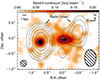 |
Fig. 1. ALMA band 6 continuum map (background color map and solid gray contours) overlaid with the ATCA 18 GHz continuum map (dashed black contours). The axis coordinates are relative to the kinematic center (white star). The synthesized beams of the ALMA and the ATCA observations are shown in the bottom left and the bottom right corners, respectively. The contours in the ALMA map are at S/N = 3 × (1, 2, 4), and those in the ATCA map are at S/N = 3 × (1, 2, 4, 8, 16, 32). |
To create a continuum map that contained only dust emission, we used the following procedure to remove the eastern synchrotron component. We first interactively drew a mask that only enclosed the synchrotron component in the tclean task (with savemodel=‘modelcolumn’). Next, we subtracted the synchrotron clean component from the original uv-data (using the uvsub task) and repeated the imaging. The top left panel of Fig. 2 shows the outcome of this procedure.
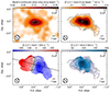 |
Fig. 2. Maps of dust-only continuum emission (top left), [C I] (2−1) integrated-intensity (moment-0, top right), intensity-weighted velocity (moment-1, bottom left), and intensity-weighted line broadening (moment-2, bottom right). The axis coordinates are relative to the kinematic center (white star). The synthesized beams are shown in the lower left corner of each panel. In the dust-only continuum map, the contours correspond to S/N = 3 × (1, 2, 4). The RMS noise of the dust continuum is ∼0.012 mJy beam−1. In the moment-0 map, the contours correspond to S/N = 3 × (1, 2, 4). The S/N is calculated by 3DBAROLO, which follows the procedure in Lelli et al. (2014). In the moment-1 map, the dashed black contours show a line-of-sight velocity of ±50, ±100, and ±200 km s−1 with respect to the systemic velocity (set to zero; solid black contour). The dashed black line represents the kinematic major axis. In the moment-2 map, the contours are the same as in the moment-0 map. |
The [C I] (2−1) moment maps were constructed with 3D-Based Analysis of Rotating Object via Line Observations (3DBAROLO, Di Teodoro & Fraternali 2015), considering the [C I] (2−1) signal within a fiducial mask created by the task Smooth & Search (see Section 4). The moment maps are shown in Fig. 2. The new ALMA data unambiguously confirm and spatially resolve the rotating disk identified in Lelli et al. (2018). In addition, the moment maps reveal a gas tail southwest of the rotating disk. In Section 4.4, we present a detailed 3D analysis that reveals a kinematically anomalous component on the blueshifted side of the disk and a second, weaker gas tail on the redshifted side to the east. It is possible that these three different noncircular components have a common physical origin, as we discuss in Section 6.1.
3.2. Radial surface brightness profiles
Radial surface brightness profiles provide an effective 1D description of the dust and gas distribution in galaxies. They are useful for measuring characteristic scale lengths, such as the effective radius (Re), which contains half of the total flux. They are also needed to study the overall mass distribution of galaxies because the radial surface density profiles of different baryonic components are required for computing their gravitational field in the galaxy midplane out to infinity (see Section 5).
For the dust radial profile, we used the synchrotron-subtracted band 6 continuum image (top left panel in Fig. 2). We measured the surface brightness profile by averaging over a set of elliptical annuli, positioned according to the kinematic center, the inclination, and position angle of the rotating disk (as derived in Section 4.1). The annulus spacing was half of the beam size of the dust continuum (0.10 arcsec). The results are shown in Fig. 3 (top panel).
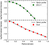 |
Fig. 3. Radial surface brightness profiles of [C I] (2−1) (top, green diamonds) and dust continuum (bottom, red squares). The random error of each data point is ≲6%. The dashed black lines show Sérsic fits to each profile. |
Ultraviolet emission from both young stellar populations and the AGN can heat up the dust grains, although the latter is expected to contribute a negligible fraction to the Rayleigh-Jeans tail of the cold dust emission (Falkendal et al. 2019; Lamperti et al. 2021). To test this effect, we measured the radial profile using the ALMA band 4 continuum map at 625 μm rest-frame as well (Huang et al. 2024). We found that the dust emission profile at band 4 is consistent with that at band 6, which confirms that the dust continuum at band 6 is dominated by cold dust grains that are heated by young stars. This is consistent with Man et al. (2019), who showed that the UV emission from the host galaxy is dominated by the young stellar population, not the AGN.
For the gas radial profile, we used a [C I] (2−1) moment-0 map integrated within ( − 550, 550) km s−1 centered at the [C I] (2−1) systematic velocity (Section 4) to account for possible faint emissions missed by the source mask. We measured the surface brightness profile using the same set of annuli as for the dust profile. The annuli spacing was half of the beam size of the [C I] (2−1) cube (0.09 arcsec). The results are shown in Fig. 3 (bottom panel).
Both profiles were fit with a Sérsic function (Sersic 1968) parameterized by the Sérsic index (n) and the effective radius (Re). The fit was made using the orthogonal-distance-regression method in scipy.odr. For the dust profile, we fit the data out to radii R = 1 arcsec and obtained n = 1.3 ± 0.2. For the gas profile, we only fit the data at R < 0.7 arcsec because we aimed to trace the inner rotating disk without the contribution from the outer gas tail. We obtained n = 0.52 ± 0.01, which properly captures the inner flattening of the gas profile. The best-fit radial density profiles are shown in Fig. 3, and the best-fit parameters are given in Table 1.
Outputs of the Sérsic fits to the gas and dust surface brightness profiles.
4. Gas kinematics
We studied the gas kinematics of PKS 0529–549 using 3DBAROLO (Di Teodoro & Fraternali 2015). In 3DBAROLO, a rotating disk is modeled with a set of tilted rings, each characterized by five geometric parameters: The center coordinates (x0, y0), the systemic velocity (Vsys), the position angle (PA), and the inclination (i). The rings are also characterized by five physical parameters: The rotation velocity (Vrot), the radial velocity (Vrad), the velocity dispersion (σv), the surface density (Σgas), and the vertical thickness (z0). The tilted-ring model was convolved with the telescope beam and was then iteratively compared with the observations to obtain the best-fit parameters.
The 3D fit of 3DBAROLO was performed on a masked cube that mostly included real line emission and avoided noisy pixels. We generated the source mask by setting MASK=SMOOTH&SEARCH, FACTOR = 1.8 (the factor by which the cube is spatially smoothed before the source search), SNRCUT = 4 (primary signal-to-noise S/N threshold), GROWTHCUT = 3 (secondary S/N threshold to growth the primary mask), and MINCHANNELS = 2 (minimum number of channels for an accepted detection). A different choice of the source mask would not substantially change our general results.
Within the source mask, the [C I] (2−1) disk of PKS 0529–549 can be fit with five rings. The width of each ring was 0.09 arcsec, which is half of the beam size of the [C I] (2−1) cube. We set NORM=AZIM so that the observed moment-0 map was azimuthally averaged to obtain the Σgas of each ring in the model. For the vertical density distribution, we assumed an exponential profile (LTYPE = 3) with a fixed scale height of 300 pc (∼0.04 arcsec). The disk scale height is much smaller than the [C I] (2−1) beam (0.18 arcsec) and therefore has a negligible impact on the kinematic fitting. We also fixed Vrad = 0 because there are no indications for strong radial motions, which generally produce a nonorthogonality between the kinematic major and minor axes (e.g., Lelli et al. 2012a,b; Di Teodoro & Peek 2021). Therefore, seven free parameters needed to be optimized: x0, y0, Vsys, PA, i, Vrot, and σv. To obtain the rotation curve, we first estimated the geometric parameters and then fit the kinematic parameters (Vrot and σv) with the disk geometry fixed.
4.1. Disk geometry
We first ran 3DFIT on the [C I] (2−1) cube and left all seven parameters free. To estimate the overall geometry, all pixels were weighted uniformly (WFUNC = 0), and both sides of the rotating disk were considered (SIDE=B). We set the initial PA = 75° and initial i = 50°. We also set DELTAPA = 15 and DELTAINC = 15 such that PA and i could explore the parameter space within ±15° around their initial guesses. The initial value of σv was 30 km s−1 (Lelli et al. 2018). We let 3DBAROLO guess the initial values of Vsys and Vrot automatically.
After several tests, we found that the kinematic center was difficult to measure because the best-fit value did not coincide with the kinematic minor axis (defined by the iso-velocity contour equal to Vsys), as expected for a rotating disk. This is likely due to the disturbed gas kinematics on the approaching side of the disk. Therefore, we fixed the kinematic center of the galaxy to (RA, Dec) = (5h30m25.447s, −54° 54′23.165″) so that it lay along the kinematic minor axis (see the bottom left panel of Fig. 2), and we repeated the fits with five free parameters.
Table 2 summarizes the disk geometric parameters that were fit by 3DBAROLO. The adopted values of Vsys, PA, and i were measured as the median values across different rings. The uncertainties were estimated as
 (1)
(1)
Disk geometry parameters of PKS 0529–549.
where N = 5 is the number of rings, MAD is the median absolute deviation across the rings, and δi are the individual errors on the given parameter at each ring. Under the radical sign, the first term considers the variation among different rings, and the second term considers the uncertainty of each ring.
The best-fit PA and i are perfectly consistent with the values from Lelli et al. (2018) of 75° and 50°, respectively. For this inclination angle, Vrot is not sensitivity to the inclination correction; for example, Vrot only changes by ∼10% when i varies from 50° to 60°.
4.2. Rotation velocity and velocity dispersion
Fixing the geometric parameters, we ran SPACEPAR in 3DBAROLO to search for global minima in the parameter space of Vrot − σv. We explored Vrot within [200, 450] km s−1 and σv within [1, 200] km s−1, both with a grid step of 1 km s−1. The residual function to be minimized was |M − D| (FUNC = 2), where M and D are the intensity values at each 3D voxel of the model and the data cube, respectively. To examine the effect of noncircular motions (e.g., the enhanced kinematic irregularities on the blueshifted side), we ran SPACEPAR separately on the approaching (blueshifted, SIDE=A) and receding sides (redshifted, SIDE=R), as well as simultaneously on both sides (SIDE=B).
Figure 4 shows Vrot and σv of each ring optimized on different sides. The rotation velocities are consistent within the errors among the three different runs. When we fit only the approaching side, the velocity dispersion showed an elevated value at R ≃ 0.135″, which is likely due to complex noncircular motions and not a real increase in the gas turbulence (see Fig. 5). The noncircular motions are examined in detail in Section 4.4.
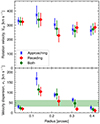 |
Fig. 4. Rotation velocity and velocity dispersion of the [C I] (2−1) disk by fitting the approaching side (blue crosses), the receding side (red diamonds), and both sides (green dots). The green band is centered at the median σv = 47 km s−1 from the two-side fitting and has a half-width of 16 km s−1, representing the uncertainty of σv (see Section 4.2). |
The current data are unable to properly constrain the radial profile of the gas velocity dispersion, and we therefore calculated the median σv from the two-side fitting (47 ± 16 km s−1) and used it as our fiducial estimate of the intrinsic gas velocity dispersion. The uncertainty was calculated using Eq. (1). This measurement of σV is consistent within the errors with the fiducial upper limit of ∼30 km s−1 estimated by Lelli et al. (2018).
As a final step, we reran 3DFIT, fixing σv = 47 km s−1 and leaving only Vrot free. We set WFUNC = 2 to give more weights along the kinematic major axis. Figure 5 compares the position-velocity (PV) diagram along the kinematic major axis of the observed cube with the best-fit model cube. Overall, the disk model describes the observations well. In particular, the thickness of the observed PV diagram is well reproduced by the model, indicating that the velocity dispersion is reasonable. Noncircular motions that cannot be reproduced by the rotating disk model are described in detail in Section 4.4.
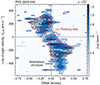 |
Fig. 5. Position-velocity diagram along the kinematic major axis. The systemic velocity of the rotating disk is set at VLOS = 0 km s−1. The color scale and the blue contours show the observed [C I] (2−1) data. The red contours and yellow dots show the best-fit rotating disk model and the rotation velocity projected along the line of sight, respectively, assuming a constant velocity dispersion (σv = 47 km s−1). The contour levels are at S/N = ( ± 2, 3, 5), and negative contours are shown with dashed gray lines. |
4.3. Asymmetric drift correction
The gas disk of PKS 0529–549 is supported by rotation and has a median Vrot/σv = 6 ± 3. The uncertainty was calculated by propagating the errors on Vrot and σv, which were estimated using Eq. (1). Turbulent motions, however, may provide non-negligible pressure support, and we therefore estimate the asymmetric drift correction (ADC) to obtain the circular velocity (Vc) that directly relates to the gravitational potential.
The ADC depends on the radial gradients of σv and Σgas (see, e.g., Eq. (4) in Lelli 2023). In 3DBAROLO, the ADC can be computed using polynomials to describe the radial profiles of σv and Σgas. Figure 6 shows the resulting Vc(R) assuming a constant σv = 47 km s−1 or a radially varying σv(R) (taken from the two-side fitting). We found that the values of Vrot and the two versions of Vc are consistent within the errors, confirming that the rotation support is dominant while pressure support is nearly negligible. Hereafter, we use Vc from a radially constant σv for simplicity.
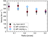 |
Fig. 6. Circular-velocity curve of PKS 0529–549 after correcting for pressure support. The black dots with error bars show the observed rotation velocity from 3DFIT. The red squares and the blue diamonds show the circular velocities after asymmetric drift correction assuming a constant σv and a radially varying σv, respectively. |
4.4. Noncircular motions
The channel maps (Fig. 7) show that some noncircular motions cannot be reproduced by the rotating-disk model: (1) A gas tail southwest of the rotating disk at line-of-sight (LoS) velocities from −191 to −88 km s−1 (SW tail), (2) a second weaker gas tail east of the rotating disk at LoS velocities from 274 to 377 km s−1 (E tail) and (3) an anomalous structure at R ≃ 0.1 − 0.3″ at LoS velocities from −501 to −346 km s−1 (see also Fig. 5). These noncircular components are also visible in the residual [C I] (2−1) moment-0 map (left panel of Fig. 8), which was obtained by subtracting the best-fit model cube from the observed cube.
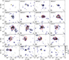 |
Fig. 7. Channel maps of the [C I] (2−1) cube, showing every other channel. The grayscale and the blue contours show the observed [C I] (2−1) data. The red contours show the best-fit rotating-disk model (Section 4). The contour levels are at S/N = ( ± 2, 3, 5), and negative contours are shown with dashed gray lines. The axis coordinates are relative to the kinematic center (golden star). The line-of-sight velocities are relative to the redshift of the [C I] (2−1) line. The synthesized beam of the [C I] (2−1) cube is shown in the bottom left corner of each panel. |
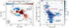 |
Fig. 8. Non-circular motions of PKS 0529–549. Left: Residual [C I] (2−1) map obtained by subtracting the best-fit rotating-disk model from the observed moment-0 map. The synthesized beam of the [C I] data is shown in the lower left corner. The axis coordinates are relative to the kinematic center (white star). The dashed circles show the aperture for measuring the flux of the enclosed structures. The black contours correspond to S/N = 3 × (1, 2, 3) of the residual map. The dashed blue arrow indicates the path for extracting the PV diagram on the right. The upper left end of the arrow indicates the width of the path. The dotted blue ticks indicate offsets of 0.0 arcsec, 0.5 arcsec, 1.0 arcsec, and 1.5 arcsec along the path. Right: Position-velocity diagram along the path on the left. The color-coding and the contour levels are the same as those in Fig. 5. |
To better visualize the tail-like structures, we constructed so-called Renzograms (Sancisi 1976) from the [C I] (2−1) cube by integrating over the velocity intervals of the two gas tails specified above, and overlaid them on the dust-only continuum map (Fig. 9). While the contours around the kinematic center are influenced by emission from the rotating disk (especially for the blue contours), the outer parts mostly trace the gas tails, possibly extending beyond the main body of the galaxy disk. The SW tail is significantly detected at S/N > 3, and the E tail is detected at S/N ∼ 2 − 3.
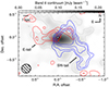 |
Fig. 9. [C I] (2−1) Renzograms (red and blue contours) overlaid on the dust-only continuum map (grayscale and dotted gray contours). The blue and red contours show narrow [C I] (2−1) moment-0 maps integrated within LoS velocities from −191 to −88 km s−1 and 274 to 377 km s−1, respectively. The contour levels are at S/N = (2, 3, 5). A single contour at S/N = 2 of the dust continuum is also shown. The synthesized beam of the dust continuum is shown in the lower left corner. |
The right panel of Fig. 8 shows a PV diagram extracted along the path in the left panel, averaging over a width of 0.225 arcsec. It is difficult to tell whether the anomalous structure and the SW tail are kinematically connected because the eventual connection occurs at the same LoS velocities as for the gas disk. The physical nature of these three noncircular components remains unclear and is discussed in Section 6.1. A sensible hypothesis is that these are two leftover tidal tails from a past major merger and a gas inflow toward the galaxy center that might be related to the SW tail.
Using the residual [C I] (2−1) moment-0 map, we estimated the [C I] (2−1) flux associated with the noncircular motions. We summed over pixels with S/N > 3 enclosed by the apertures shown in the left panel of Fig. 8. The fluxes and fiducial uncertainties are given in Table 3, but we stress that these values are lower limits. Because the rotating-disk model assumes axisymmetry, the flux in the observed moment-0 map is azimuthally averaged over the rings, including the flux of the noncircular motions. This explains why the residuals along the minor axis of the galaxy are systematically negative. The low-S/N pixels associated with the gas tails were also discounted. The noncircular motions cause at least 12% of the total flux in the gas disk (2.8 ± 0.3 Jy km s−1). We discuss the noncircular motions further in Section 6.1.
[C I] (2−1) fluxes of the noncircular components.
5. Mass models
5.1. Bayesian rotation-curve fitting
In this section we build a set of mass models with different combinations of mass components (gas, star, and dark matter halo). The model circular velocity (Vmod) was therefore determined by several free parameters p, which depend on the mass components included. To determine the parameter values and uncertainties, we used a Markov chain Monte Carlo (MCMC) method to sample the posterior probabilities of the free parameters (see Appendix A for details).
In Bayesian inference, the posterior probability distribution of the free parameters is the product of the likelihood function (based on new observations) and their priors (based on previous knowledge or assumptions). We defined the likelihood function as ℒ = exp(−0.5χ2) with
![Mathematical equation: $$ \begin{aligned} \chi ^{2}=\sum _{k = 1}^{N}{\frac{[V_{\rm c}-V_{\rm mod}(\boldsymbol{p})]^{2}}{\delta _{V_{\rm c}}^{2}}}, \end{aligned} $$](/articles/aa/full_html/2025/01/aa50814-24/aa50814-24-eq3.gif) (2)
(2)
where Vc is the observed circular velocity at the kth radius Rk, and δVc is the associated uncertainty.
In addition to the free parameters in Vmod, the disk inclination i was treated as a nuisance parameter. We imposed a Gaussian prior on i centered at i0 = 53° and with a standard deviation of 5° to account for the observational uncertainties (see Section 4.1 and Table 2). For a sampling in the parameter space of i, Vc and δVc accordingly change by a factor of sin(i0)/sin(i).
In the following sections, we explore different mass models and clarify the priors on the related free parameters. We start with partial mass models with a limited number of baryonic components; these models are probably unphysical, but they are useful for setting hard upper limits on gas and stellar masses. Next, we build complete mass models, but we caution that the masses of the different components are often degenerate. The best-fit models are shown in Figs. 10 and 11, and the MCMC corner plots are shown in Figs. A.1 and A.2. The median values and associated uncertainties of parameters of each model are presented in Table 4.
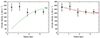 |
Fig. 10. Partial mass models: Gas only (left panel) and stars only (right panel). The black dots with error bars show the observed circular velocities in both panels. The gravitational contributions from gas and stars are shown with a dotted green line and a dashed brown line, respectively. |
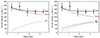 |
Fig. 11. Complete mass models: Baryons only (left panel) and baryons+DM (right panel). The black dots with error bars show the observed circular velocities in both panels, while the black line shows the best-fit mass model. The gravitational contribution from gas, stars, and DM are shown with a dotted green line, a dashed brown line, and a dash-dotted purple line, respectively. |
5.2. Partial mass models
5.2.1. Gas only
To set a hard upper limit on the gas mass, we started with a minimalist mass model in which the gas disk was the only dynamically important component. This mass model is probably unphysical; as we show, it cannot reproduce the observed rotation curve.
The gas gravitational contribution (Vgas) was calculated by numerically solving the Poisson’s equation for a finite-thickness disk with a density profile ρ(R, z) = Σ(R)ξ(z), where Σ(R) is the radial surface density profile, and ξ(z) is the vertical profile. To do this, we used the vcdisk package1. For Σ(R), we took the Sérsic profile fit to the [C I] (2−1) surface brightness profile in Section 3.2. For ξ(z), we assumed an exponential distribution with a constant scale height of 300 pc.
For practical reasons, we calculated Vgas for a normalization mass (M0) defined for R → ∞, and we introduced a dimensionless scaling factor Υgas = Mgas/M0 of the order of unity, where Mgas is the actual gas mass. Therefore, we had  . For numerical convenience, we took M0 = 1011 M⊙ and applied hard boundaries on log(Υgas)∈(−2, 2). Therefore, Mgas has a uniform uninformative prior within (109, 1013) M⊙.
The best-fit model gives Mgas = 8.6 × 10¹⁰ M⊙. This value, as we discuss in Section 6.2.1, is comparable to the molecular gas mass inferred from the CO J = 4 − 3 (hereafter CO (4−3)) flux, but it is three times lower than the masses inferred from [C I] and dust emissions (Huang et al. 2024).
The left panel of Fig. 10 shows that it is impossible to reproduce the inner parts of the rotation curve with the gas disk component alone. The high rotation velocities in the innermost two rings require a central mass concentration, such as a stellar spheroid and/or a supermassive black hole.
5.2.2. Stars only
We now consider a mass model in which Vmod is fully determined by the stellar component while the gas contribution is neglected. Since PKS 0529–549 is very bright in [C I], this model corresponds to a scenario in which the [C I]-to-Mgas conversion factor is extremely small (see discussions in Section 6.2.1), so that the gravitational contribution from gas is much smaller than that from stars. This model is probably unrealistic, but it is useful for setting hard upper limits on the stellar mass.
Given the lack of high-resolution optical/NIR imaging for PKS 0529–549, we cannot directly compute V⋆ using the observed stellar surface brightness profile (as for Vgas). Therefore, we adopted a sensible parametric function for the stellar mass distribution by assuming a spherical stellar component described by a Sérsic profile. The stellar gravitational contribution at radius R is then given by
 (3)
(3)
where the fitting parameters are the stellar mass M⋆, the stellar half-mass radius Re, ⋆, and the Sérsic index n⋆. The parameters p and b are functions of n⋆. The incomplete and complete gamma functions are denoted as γ and Γ, respectively (see Terzić & Graham 2005). Similarly to Section 5.2.1, we calculated V⋆ for a normalizing mass M0 = 1011 M⊙ and introduced a dimensionless parameter Υ⋆ = M⋆/M0 so that Vmod2 = Υ⋆V⋆2. We applied uniform priors on n⋆ ∈ (0.5, 10), log(Υ⋆)∈(−2, 2), and Re, ⋆ ∈ (0.1, 5) kpc.
The right panel of Fig. 10 shows that this single-component model can fit the observed rotation curve. The best-fit n⋆ = 5.7 reconfirms that the stellar mass distribution should be centrally concentrated, but Re, ⋆ is unconstrained (see the corner plot in Fig. A.1). Because the model neglects gas and DM contributions, the best-fit stellar mass (∼1.1 × 10¹¹ M⊙) represents a hard upper limit on the actual stellar mass of the galaxy. This value is not sensitive to Re, ⋆, as is shown in Fig. A.1, and it is about a factor of three lower than the value estimated from the SED fitting (De Breuck et al. 2010, 3 × 10¹¹ M⊙). We discuss possible reasons for this discrepancy in Section 6.2.2.
We also explored a mass model (Fig. A.3) in which the stellar component was given by the sum of an exponential disk and a De Vaucouleurs bulge (with n⋆, bul = 4). This multicomponent mass model has four strongly degenerate parameters: the stellar masses, and the effective radii of each component. Since our main aim is to obtain an upper limit on the total stellar mass, the effective radius of the disk was fixed to be equal to that of the dust component Re, dust (Fig. 3), while that of the bulge was fixed to 0.1 × Re, dust. This multicomponent model also fits the rotation curve well and returns a total stellar mass (bulge plus disk) of ∼8 × 10¹⁰ M⊙. This mass is slightly lower than the one from the single-component spherical model because of the well-known fact that a highly flattened mass distribution implies higher circular velocities than the equivalent spherical mass distribution (e.g., Lelli 2023). The bulge-to-disk ratio is ∼0.9, but this value is highly uncertain and depends on the adopted effective radii. Future high-resolution NIR images are needed to constrain the stellar mass distribution better.
5.3. Complete mass models
5.3.1. Baryons only
Compared to the single-component models, a more complete model includes the gravitational contributions of both gas and stars. In this case, Vmod2 = ΥgasVgas2 + Υ⋆V⋆2.
To alleviate the degeneracy among the parameters, we added the following physically motivated priors:
-
A log-normal prior on Υgas. Based on the CO (4−3) flux, the CO line ratio r41 = 0.46, and a CO conversion factor αCO = 0.8, Huang et al. (2024) estimate that the molecular gas mass of PKS 0529–549 is 7.3 ± 0.9 × 10¹⁰ M⊙. Considering the uncertainties of the assumed CO conversion factor and the CO line ratio, we centered the prior of log(Υgas) at −0.14 with a standard deviation of 0.7 (a factor of 5 for Υgas).
-
A Gaussian prior on n⋆. In Section 5.2.2, we have demonstrated that the high circular velocities at small radii require the stellar profile to be centrally concentrated. Therefore, we centered the prior at n⋆ = 4 with a standard deviation of 2 because the vast majority of stellar spheroids have Sérsic indexes between ∼2 (e.g., pseudo-bulges) and ∼6 (such as compact ellipticals, Lacerna et al. 2020).
The left panel of Fig. 11 combines the gravitational contribution of the gas and stars. The Mgas and M⋆ values in this model are 1.8 × 10¹⁰ M⊙ and 7.0 × 10¹⁰ M⊙, respectively. As expected, both masses decrease with respect to those in the partial models. The stellar component dominates the total gravitational contribution because otherwise, the circular velocities at the innermost radii cannot be recovered.
5.3.2. Baryons plus dark matter
In Section 5.3.1 we show that the rotation curve of PKS 0529–549 is well fit by a baryon-only model with sensible baryonic masses. Therefore, it is immediately clear that the DM contribution is unconstrained due to the disk-halo degeneracy (van Albada et al. 1985; Lelli 2023). Nevertheless, we tentatively added a Navarro-Frenk-White (NFW) dark matter halo with constraints based on ΛCDM cosmology. In this way, we were able to examine whether the observed rotation curve was consistent with the expectations from the ΛCDM cosmology.
The NFW-profile was parameterized by the halo concentration C200 and the halo mass M200 (or equivalently, the halo velocity V200). When the contributions of both baryons and the NFW DM halo are included, Vmod is thus given by
 (4)
(4)
where VNFW is the circular velocity of the NFW halo (Eq. (10) in Li et al. 2020). In addition to the baryonic priors described in Section 5.3.1, we used two ΛCDM scaling relations as DM priors:
-
A log-normal prior on M200. Legrand et al. (2019) determined the stellar-to-halo mass relations in different redshift bins using a parametric abundance matching technique. We related the mean M200 to M⋆ through their Eq. (1) with their best-fit parameters at z = [2, 2.5]. A conservative scatter in log(M200) of 0.2 was adopted.
-
A log-normal prior on C200. Dutton & Macciò (2014) fit the M200 − C200 relation from N-body cosmological simulations. The mean C200 is related to M200 through their Eq. (7) with redshift-dependent parameters given by their Eqs. (10) and (11). We adopted a scatter of 0.11 in log(C200).
Compared to the baryons-only model, including a DM halo decreases the gas mass and stellar mass, but these different estimates are all consistent within the uncertainties. Even though the DM contribution is not constrained, the rotation curve of PKS 0529–549 is consistent with the expectations from the ΛCDM cosmology.
6. Discussion
PKS 0529–549 is about 10 − 100 times more luminous in the [C I] line than the majority of high-z radio galaxies (HzRG, Kolwa et al. 2023). This enables us to study its gas distribution and kinematics in detail. On the other hand, the SFR of PKS 0529–549 ( M⊙ yr−1, Falkendal et al. 2019) indicates that its ISM condition is probably extreme (e.g., strong UV field, cosmic-ray intensity, gas turbulence, and high gas density and temperature), which might complicate the abundances of molecular gas tracers and the excitation of molecular lines.
6.1. Circular and noncircular motions
In Section 4 we show that PKS 0529–549 has a regular rotating disk, with Vrot/σv = 6 ± 3. This value is higher than what is predicted by the disk-instability model from Wisnioski et al. (2015) at the redshift of PKS 0529–549, but is consistent with recent ALMA observations in a significant sample of high-z star-forming galaxies (Lelli et al. 2023; Rizzo et al. 2023, 2024). Given that PKS 0529–549 is an AGN-host starburst with an extreme SFR of  M⊙ yr−1 (Falkendal et al. 2019), it is surprising that its gas disk is still dynamically cold.
In addition to the overall regular rotation of the gas disk, there are clear signatures of noncircular motions, that is, the SW tail, the E tail, and the anomalous structure (Section 4.4). The gas tails may be remnants of a past major merger event, which could have triggered a gas inflow (possibly related to the anomalous kinematic structure near the center), and therefore, the high star-formation rate and radio-loud AGN activity of the galaxy. Alternatively, the two gas tails may be spiral arms in a more extended gas disk, while the kinematically anomalous component may be something unrelated, such as a gas outflow. Future images from the Hubble Space Telescope (HST) or the James Webb Space Telescope (JWST) are key to elucidating their origins.
Considering the fraction of noncircular motions in the total flux of PKS 0529–549 as well as the gas mass obtained using the gas-only mass model, we obtained hard upper limits on the gas mass of the noncircular structures, which is about 1.0 × 10¹⁰ M⊙. We assumed that the flux-to-mass conversion factors are the same in the rotating disk and the noncircular structures. When we take the gas mass from the baryons+DM mass model, the mass of the noncircular motions decreases to 1.7 × 10⁹ M⊙. In both cases, the molecular gas involved in the noncircular components is a minor fraction (12%) of the total gas mass that resides in the rotating disk.
6.2. Discrepancies in different mass estimates
Mass models that are fit to the observed [C I] rotation curve allow us to obtain dynamical upper limits on the gas and stellar masses of this galaxy. In the following, we compare our mass measurements with those from independent methods. We report some puzzling discrepancies.
6.2.1. Discrepancies in gas masses and conversion factors
To estimate the total molecular gas mass (Mmol) of a galaxy, one usually measure the line luminosity of an H2-tracer and adopts a luminosity-to-mass conversion factor. For example, CO lines have been widely used (Carilli & Walter 2013). The CO-to-H2 conversion factor αCO is typically defined as the ratio of Mmol and the luminosity of the CO (1−0) line, LCO (1 − 0)′ (Bolatto et al. 2013). This conversion factor must be calibrated with an independent measurement of Mmol, such as the one derived with dynamical methods. By doing so, the underlying assumption is that molecular gas dominates the total gas mass (Mgas) in the inner galaxy regions.
In the case of PKS 0529–549, using the CO (4−3) luminosity LCO (4 − 3)′=(4.2 ± 0.5)×1010 K km s−1 pc2 (Huang et al. 2024), a typical CO line ratio of r41 ≡ LCO (4 − 3)′/LCO (1 − 0)′ = 0.5 (Carilli & Walter 2013), and the upper limit on Mgas from the gas-only mass model (Section 5.2.1), we obtained an upper limit on αCO < 1.0 (r41/0.5) M⊙ (K km s−1 pc2)−1. This is similar to what is commonly used for starbursts (∼0.8, Bolatto et al. 2013; Carilli & Walter 2013), but we stress that it is a very hard upper limit because it neglects contributions from stars and DM in the mass model. When we instead consider the gas mass from the complete mass model with baryons plus DM, we find αCO = 0.17 (r41/0.5) M⊙ (K km s−1 pc2)−1.
Using the [C I] (1−0) luminosity ![Mathematical equation: $ L_\mathrm{[C\,\textsc{i}]}{\prime}=(3.12\pm0.67)\times10^{10} $](/articles/aa/full_html/2025/01/aa50814-24/aa50814-24-eq31.gif) K km s−1 pc2 (Huang et al. 2024) and the upper limit of Mgas from the gas-only model, we obtained an upper limit on the [C I]-to-Mgas conversion factor
K km s−1 pc2 (Huang et al. 2024) and the upper limit of Mgas from the gas-only model, we obtained an upper limit on the [C I]-to-Mgas conversion factor ![Mathematical equation: $ \alpha_\mathrm{[C\,\textsc{i}]}\equiv M_{\mathrm{gas}}/L_\mathrm{[C\,\textsc{i}]}{\prime} < 2.8\pm0.8 $](/articles/aa/full_html/2025/01/aa50814-24/aa50814-24-eq32.gif) M⊙ (K km s−1 pc2)−1. This value is about one-seventh of the mean value in high-z metal-rich galaxies (∼20, Dunne et al. 2022). When we consider the gas mass from the complete mass model with baryons plus DM, the inferred value of α[C I] decreases to 0.4 M⊙ (K km s−1 pc2)−1, which is 50 times lower than the usual value.
M⊙ (K km s−1 pc2)−1. This value is about one-seventh of the mean value in high-z metal-rich galaxies (∼20, Dunne et al. 2022). When we consider the gas mass from the complete mass model with baryons plus DM, the inferred value of α[C I] decreases to 0.4 M⊙ (K km s−1 pc2)−1, which is 50 times lower than the usual value.
One possibility is that PKS 0529–549 has a [C I]/H2 abundance ratio of at least seven times the value taken for local ultraluminous infrared galaxies (∼3 × 10⁻⁵, Papadopoulos & Greve 2004). If PKS 0529–549 is the progenitor of a local early-type galaxy (ETG), we may indeed expect that its star-forming gas is already significantly enriched (e.g., Thomas et al. 2005, 2010). Moreover, considering the intense star formation and AGN activity in PKS 0529–549, the [C I]/H2 ratio can also be enhanced by dissociating far-UV photons and cosmic rays (Bisbas et al. 2024).
Another possibility is that the radiative transfer of [C I] lines is complicated by the intense star formation and AGN activity, leading to enhanced [C I] emission and the failing of the usual conversion factor. Moreover, the [C I] (1−0) flux is very uncertain, and there may be spatial variations in the [C I] line ratio that we cannot probe with the current data.
6.2.2. Discrepancies in stellar masses
The upper limit on M⋆ given by the star-only mass model is lower by about a factor of ∼3 than the value estimated from fitting the spectral energy distribution (SED) with stellar population models (De Breuck et al. 2010). The discrepancy increases to a factor of ∼6 when the gravitational contributions of gas and DM are included in the mass models. The discrepancy is quite serious, and we therefore discuss three possibilities to explain it: (1) The SED fitting overestimates the stellar mass; (2) the rotating disk is not in full equilibrium, so that the circular velocities underestimate the dynamical mass; and (3) there are two different galaxies along the line of sight.
(1) Regarding the SED fitting, the stellar mass comes from De Breuck et al. (2010), where 70 HzRGs were studied based on Spitzer photometry. The SED fitting assumes an elliptical galaxy template for the stellar component, which may not be ideal for PKS 0529–549 given its high SFR (Falkendal et al. 2019). Two or three blackbody functions were assumed for dust emissions. The inherent uncertainty of the stellar mass derived from the SED fitting (Seymour et al. 2007) is smaller than its difference from the stellar mass derived using dynamic mass models. To further investigate the issue, we constructed a new SED with 22 photometric points from the rest-frame optical to the radio, using data from Gemini Flamingos-2, the VLT Infrared Spectrometer And Array Camera (ISAAC), Spitzer/MIPS and IRAC, Herschel/SPIRE and PACS, ALMA bands 4 and 6, and ATCA. Preliminary SED fittings with Code Investigating GALaxy Emission (CIGALE, Boquien et al. 2019) showed that the best-fit stellar mass can range from 0.4 × 10¹¹ to 1.2 × 10¹¹ M⊙ depending on the chosen AGN model, which means that it may be consistent with the M⋆ inferred based on dynamic mass models. The SED fittings are not fully satisfactory, however, especially in the AGN-dominated far-infrared portion of the spectrum. We will therefore investigate this issue in more detail in a future paper, in which we will test different SED fitting codes and AGN models.
(2) Regarding the dynamical equilibrium, the [C I] (2−1) velocity field is relatively symmetric and shows regular rotation (Fig. 2), which is commonly interpreted as the cold gas being in equilibrium with the gravitational potential. Our 3D kinematic modeling, however, revealed an anomalous kinematic structure in the approaching side of the disk (Fig. 5) and two extended gaseous tails. If PKS 0529–549 has indeed undergone a recent major merger, the inner disk may not have had enough time to relax with the overall gravitational potential, so that the dynamical mass might be underestimated (Lelli et al. 2015).
Using the outermost measured point of the rotation curve, we estimated the orbital time of PKS 0529–549, which is torb ∼ 80 Myr. This is longer than the time from the two recent bursts of star formation: 6 Myr and > 20 Myr (Man et al. 2019). If the two star formation bursts are driven by a major merger, it is therefore possible that the gas disk of PKS 0529–549 is not relaxed because it did not have enough time to complete several rotations since the time of the latest starburst. Custom-built hydrodynamical simulations are needed to investigate whether such a merger event might be strong enough to drive the rotating disk out of dynamical equilibrium, leading to a systematic underestimation of the dynamical mass.
(3) Regarding the third possibility, the scenario is that there are two galaxies that are roughly aligned along the line of sight: a [C I]-emitting, gas-rich, star-forming galaxy in the foreground and a [O III]-emitting, gas-poor, AGN-dominated galaxy in the background. As strange as it may sound, several clues point in this direction.
First, the [O III] λ5007 emission is systematically redshifted with respect to the [C I] (2−1) emission (Fig. 12). The redshifts of [C I] (2−1) and [O III] λ5007 lines are 2.5706 ± 0.0002 and 2.5745 ± 0.0001 (Nesvadba et al. 2017), respectively. Their redshift difference corresponds either to a velocity difference of ∼350 km s−1 with respect to the [C I] (2−1) rest frame, or to a comoving distance difference of ∼4.5 Mpc when we consider the [C I] and [O III] redshifts as distinct reference frames. Given the cosmological scale-factor of 0.28 at z = 2.57, the physical distance between the [C I] and [O III] emitters would be of 1.3 Mpc, which means that the two putative galaxies are probably unbound.
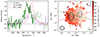 |
Fig. 12. Comparison of the ALMA, VLT/SINFONI, and VLT/X-Shooter data (see also Lelli et al. 2018). Left: [C I] (2−1) (solid green) and [O III] λ5007 (dashed red) line profiles extracted from an aperture with a diameter of 1 arcsec, centered at the kinematic center. The He IIλ1640 (dash-dotted violet) line is adapted from Man et al. (2019). The velocities of [C I] (2−1), [O III] λ5007, and He IIλ1640 are relative to the redshift of [C I] (2−1) line (z = 2.5706 ± 0.0002). The CO (7−6) emission adjacent to [C I] (2−1) is marked with a dotted green line (not shifted in velocity). Right: [O III] velocity field (adapted from Nesvadba et al. 2017; Lelli et al. 2018) overlaid with the radio lobes from ATCA 18 GHz (black contours). The line-of-sight velocities are shown with respect to the redshift of [C I] (2−1). The kinematic major axes of the [C I] (2−1) and [O III] λ5007 lines are shown by the dashed green and the dash-dotted red lines, respectively. The FWHM of the SINFONI point-spread function (0.7 arcsec × 0.6 arcsec) is shown in the bottom left corner. The axis coordinates are relative to the kinematic center (white star). |
Second, the [O III] λ5007 kinematic major axis is offset by ∼30° with respect to the [C I] disk major axis (see Fig. 12). This fact was already reported by Lelli et al. (2018, see their Fig. 1), who interpreted the [O III] emission as coming from the redshifted far side of an ionized gas outflow because the [O III] kinematic major axis is well aligned with the AGN-driven radio lobes.
Discrepant redshifts from several different lines were also found in Man et al. (2019) using rest-frame UV absorption lines from VLT/X-Shooter observations. This two-galaxy scenario is similar to the configuration of the Dragonfly galaxy (Lebowitz et al. 2023), where two galaxies (although both are gas rich) are merging, while one of them hosts an AGN and two radio lobes. To test this scenario, we need high-resolution images from HST or JWST to possibly discern two separate stellar components.
6.3. Disk-halo degeneracy
In the previous sections, we discussed the discrepancies between stellar and gas masses from photometric and dynamical methods. These discrepancies already emerge when we consider single-component mass models, which provide hard upper limits to the mass of each individual component. Clearly, the discrepancies become even more severe when we consider two-component models (gas and stars) or multicomponent models with a DM halo. These facts highlight the severity of the disk-halo degeneracy at high-z (Lelli 2023): When we cannot measure with high confidence the stellar and gas masses with photometric methods, there is little hope of measuring the DM content.
The disk-halo degeneracy has been a long-standing issue in building mass models at z = 0 (van Albada et al. 1985). In particular, van Albada & Sancisi (1986) showed that one needs to know the baryonic mass with an accuracy of about 25% to fully break the degeneracy, even when extended rotation curves from H I observations are available (see their Fig. 5). For galaxies at cosmic noon, the stellar masses from SED fitting and the gas masses from standard methods (often based on high-J CO lines) are surely more uncertain than 25%, indicating that major observational and technical endeavours are needed to address the crucial question of the DM content of high-z galaxies.
In recent years, several studies reported DM fractions of galaxies at cosmic noon (Price et al. 2021; Nestor Shachar et al. 2023; Puglisi et al. 2023), and some of them even argued that they found evidence for DM cores (Genzel et al. 2020; Bouché et al. 2022). These works rarely discussed or investigated the disk-halo degeneracy, however, which might indicating some overconfidence in knowing the true baryonic masses of high-z galaxies. At z ≃ 0, one approach to breaking the disk-halo degeneracy has been to use NIR surface photometry in combination with dedicated stellar population models (Schombert & McGaugh 2014; Schombert et al. 2019). Even so, some systematic uncertainties remain due to the choice of the specific stellar population model and stellar initial mass function, so that additional dynamical arguments are used to set the absolute calibration of the stellar mass (McGaugh & Schombert 2015; Lelli et al. 2016a,b,c). At high-z, the current situation is much more uncertain, but rest-frame NIR imaging with JWST may be a promising route to measure robust stellar masses, while multiline gas tracer observations may allow us to measure robust gas masses, so that the disk-halo degeneracy could be ameliorated using stringent physically motivated priors when fitting the rotation curve.
7. Conclusions
We studied the gas distribution and dynamics of a radio-loud AGN-host galaxy at z ≃ 2.6, PKS 0529–549 using ALMA data of the [C I] (2−1) line with a superb spatial resolution of 0.18″ (∼1.5 kpc). Our results are summarized below.
-
The [C I] (2−1) emission forms a dynamically cold rotation-supported disk with Vrot/σv = 6 ± 3. This confirms the overall picture from low-resolution data (Lelli et al. 2018).
-
We discovered two gas tails that extend beyond the rotating disk and a kinematically anomalous gas component at ∼2 kpc from the galaxy center. These noncircular structures may be related and be due to a past merger event.
-
Our 3D kinematic modeling returned a flat rotation curve at large radii, which implies a total dynamical mass of ∼1011 M⊙ within about 3.3 kpc.
-
Mass models with multiple components display a strong disk-halo degeneracy: Models with or without a DM halo can explain the observed circular velocities equally well, so that the DM content is virtually unconstrained.
-
The dynamical upper limit on M⋆ is exceeded by the stellar masses from available SED fitting, while the dynamical upper limit on Mgas is exceeded by gas masses from the usual recipes. The origin of these discrepancies remains unclear.
High-resolution optical/NIR images, such as those from HST and/or JWST, are needed to probe the stellar mass distribution and break the disk-halo degeneracy so that the actual DM content of high-z galaxies can be measured. These images may also help us to understand the discrepancies between the different methods for estimating stellar and gas masses at high-z, which are key aspects for understanding the formation and evolution of galaxies.
Acknowledgments
L.L. and F.L. acknowledge the hospitality of ESO Garching, where most of this work was done. L.L. and Z.Y.Z. acknowledge the support from the National Key R&D Program of China (2023YFA1608204). L.L. and Z.Y.Z. acknowledge the support of the National Natural Science Foundation of China (NSFC) under grants 12173016 and 12041305. L.L. and Z.Y.Z. acknowledge the science research grants from the China Manned Space Project, CMS-CSST-2021-A08 and CMS-CSST-2021-A07. L.L. and Z.Y.Z. acknowledge the Program for Innovative Talents, Entrepreneur in Jiangsu. A.M. acknowledges the support of the Natural Sciences and Engineering Research Council of Canada (NSERC) through grant reference number RGPIN-2021-03046. P.S. acknowledges INAF Mini Grant 2022 “The evolution of passive galaxies through cosmic time”. T.G.B. acknowledges support from the Leading Innovation and Entrepreneurship Team of Zhejiang Province of China (Grant No. 2023R01008). This paper makes use of the following ALMA data: ADS/JAO.ALMA#2018.1.01669.S. ALMA is a partnership of ESO (representing its member states), NSF (USA) and NINS (Japan), together with NRC (Canada), NSTC and ASIAA (Taiwan), and KASI (Republic of Korea), in cooperation with the Republic of Chile. The Joint ALMA Observatory is operated by ESO, AUI/NRAO and NAOJ.
References
- Arribas, S., Colina, L., Bellocchi, E., Maiolino, R., & Villar-Martín, M. 2014, A&A, 568, A14 [NASA ADS] [CrossRef] [EDP Sciences] [Google Scholar]
- Begeman, K. G. 1989, A&A, 223, 47 [NASA ADS] [Google Scholar]
- Bisbas, T. G., Zhang, Z.-Y., Gjergo, E., et al. 2024, MNRAS, 527, 8886 [Google Scholar]
- Bolatto, A. D., Wolfire, M., & Leroy, A. K. 2013, ARA&A, 51, 207 [CrossRef] [Google Scholar]
- Boquien, M., Burgarella, D., Roehlly, Y., et al. 2019, A&A, 622, A103 [NASA ADS] [CrossRef] [EDP Sciences] [Google Scholar]
- Bosma, A. 1978, Ph.D. Thesis, University of Groningen, The Netherlands [Google Scholar]
- Bouché, N., Carfantan, H., Schroetter, I., Michel-Dansac, L., & Contini, T. 2015, AJ, 150, 92 [Google Scholar]
- Bouché, N. F., Bera, S., Krajnović, D., et al. 2022, A&A, 658, A76 [NASA ADS] [CrossRef] [EDP Sciences] [Google Scholar]
- Broderick, J. W., De Breuck, C., Hunstead, R. W., & Seymour, N. 2007, MNRAS, 375, 1059 [NASA ADS] [CrossRef] [Google Scholar]
- Carilli, C. L., & Walter, F. 2013, ARA&A, 51, 105 [NASA ADS] [CrossRef] [Google Scholar]
- CASA Team (Bean, B., et al.) 2022, PASP, 134, 114501 [NASA ADS] [CrossRef] [Google Scholar]
- Chen, C.-C., Hodge, J. A., Smail, I., et al. 2017, ApJ, 846, 108 [Google Scholar]
- Concas, A., Popesso, P., Brusa, M., et al. 2017, A&A, 606, A36 [NASA ADS] [CrossRef] [EDP Sciences] [Google Scholar]
- Concas, A., Popesso, P., Brusa, M., Mainieri, V., & Thomas, D. 2019, A&A, 622, A188 [NASA ADS] [CrossRef] [EDP Sciences] [Google Scholar]
- Concas, A., Maiolino, R., Curti, M., et al. 2022, MNRAS, 513, 2535 [NASA ADS] [CrossRef] [Google Scholar]
- De Breuck, C., Seymour, N., Stern, D., et al. 2010, ApJ, 725, 36 [NASA ADS] [CrossRef] [Google Scholar]
- De Breuck, C., Williams, R. J., Swinbank, M., et al. 2014, A&A, 565, A59 [NASA ADS] [CrossRef] [EDP Sciences] [Google Scholar]
- Di Teodoro, E. M., & Fraternali, F. 2015, MNRAS, 451, 3021 [Google Scholar]
- Di Teodoro, E. M., & Peek, J. E. G. 2021, ApJ, 923, 220 [NASA ADS] [CrossRef] [Google Scholar]
- Di Teodoro, E. M., Fraternali, F., & Miller, S. H. 2016, A&A, 594, A77 [NASA ADS] [CrossRef] [EDP Sciences] [Google Scholar]
- Drouart, G., De Breuck, C., Vernet, J., et al. 2014, A&A, 566, A53 [NASA ADS] [CrossRef] [EDP Sciences] [Google Scholar]
- Dunne, L., Maddox, S. J., Papadopoulos, P. P., Ivison, R. J., & Gomez, H. L. 2022, MNRAS, 517, 962 [NASA ADS] [CrossRef] [Google Scholar]
- Dutton, A. A., & Macciò, A. V. 2014, MNRAS, 441, 3359 [Google Scholar]
- Dye, S., Eales, S. A., Gomez, H. L., et al. 2022, MNRAS, 510, 3734 [NASA ADS] [CrossRef] [Google Scholar]
- Falkendal, T., De Breuck, C., Lehnert, M. D., et al. 2019, A&A, 621, A27 [NASA ADS] [CrossRef] [EDP Sciences] [Google Scholar]
- Foreman-Mackey, D. 2016, J. Open Source Softw., 1, 24 [Google Scholar]
- Förster Schreiber, N. M., Genzel, R., Bouché, N., et al. 2009, ApJ, 706, 1364 [Google Scholar]
- Genzel, R., Price, S. H., Übler, H., et al. 2020, ApJ, 902, 98 [NASA ADS] [CrossRef] [Google Scholar]
- Gnerucci, A., Marconi, A., Cresci, G., et al. 2011, A&A, 528, A88 [NASA ADS] [CrossRef] [EDP Sciences] [Google Scholar]
- Gururajan, G., Béthermin, M., Theulé, P., et al. 2022, A&A, 663, A22 [NASA ADS] [CrossRef] [EDP Sciences] [Google Scholar]
- Harrison, C. M., Alexander, D. M., Mullaney, J. R., & Swinbank, A. M. 2014, MNRAS, 441, 3306 [Google Scholar]
- Hodge, J. A., Carilli, C. L., Walter, F., et al. 2012, ApJ, 760, 11 [Google Scholar]
- Huang, H. T., Man, A. W. S., Lelli, F., et al. 2024, ApJ, 977, 251 [NASA ADS] [CrossRef] [Google Scholar]
- Humphrey, A., Zeballos, M., Aretxaga, I., et al. 2011, MNRAS, 418, 74 [NASA ADS] [CrossRef] [Google Scholar]
- Jones, G. C., Carilli, C. L., Shao, Y., et al. 2017, ApJ, 850, 180 [Google Scholar]
- Kamphuis, P., Józsa, G. I. G., Oh, S. H., et al. 2015, MNRAS, 452, 3139 [NASA ADS] [CrossRef] [Google Scholar]
- Kolwa, S., De Breuck, C., Vernet, J., et al. 2023, MNRAS, 525, 5831 [NASA ADS] [CrossRef] [Google Scholar]
- Lacerna, I., Ibarra-Medel, H., Avila-Reese, V., et al. 2020, A&A, 644, A117 [NASA ADS] [CrossRef] [EDP Sciences] [Google Scholar]
- Lamperti, I., Harrison, C. M., Mainieri, V., et al. 2021, A&A, 654, A90 [NASA ADS] [CrossRef] [EDP Sciences] [Google Scholar]
- Lebowitz, S., Emonts, B., Terndrup, D. M., et al. 2023, ApJ, 951, 73 [NASA ADS] [CrossRef] [Google Scholar]
- Legrand, L., McCracken, H. J., Davidzon, I., et al. 2019, MNRAS, 486, 5468 [NASA ADS] [CrossRef] [Google Scholar]
- Lelli, F. 2023, ArXiv e-prints [arXiv:2305.18224] [Google Scholar]
- Lelli, F., Verheijen, M., Fraternali, F., & Sancisi, R. 2012a, A&A, 537, A72 [NASA ADS] [CrossRef] [EDP Sciences] [Google Scholar]
- Lelli, F., Verheijen, M., Fraternali, F., & Sancisi, R. 2012b, A&A, 544, A145 [NASA ADS] [CrossRef] [EDP Sciences] [Google Scholar]
- Lelli, F., Verheijen, M., & Fraternali, F. 2014, MNRAS, 445, 1694 [Google Scholar]
- Lelli, F., Duc, P.-A., Brinks, E., et al. 2015, A&A, 584, A113 [NASA ADS] [CrossRef] [EDP Sciences] [Google Scholar]
- Lelli, F., McGaugh, S. S., & Schombert, J. M. 2016a, ApJ, 816, L14 [Google Scholar]
- Lelli, F., McGaugh, S. S., & Schombert, J. M. 2016b, AJ, 152, 157 [Google Scholar]
- Lelli, F., McGaugh, S. S., Schombert, J. M., & Pawlowski, M. S. 2016c, ApJ, 827, L19 [NASA ADS] [CrossRef] [Google Scholar]
- Lelli, F., De Breuck, C., Falkendal, T., et al. 2018, MNRAS, 479, 5440 [Google Scholar]
- Lelli, F., Di Teodoro, E. M., Fraternali, F., et al. 2021, Science, 371, 713 [Google Scholar]
- Lelli, F., Zhang, Z.-Y., Bisbas, T. G., et al. 2023, A&A, 672, A106 [NASA ADS] [CrossRef] [EDP Sciences] [Google Scholar]
- Levy, R. C., Bolatto, A. D., Teuben, P., et al. 2018, ApJ, 860, 92 [NASA ADS] [CrossRef] [Google Scholar]
- Li, P., Lelli, F., McGaugh, S., & Schombert, J. 2020, ApJS, 247, 31 [Google Scholar]
- Madau, P., & Dickinson, M. 2014, ARA&A, 52, 415 [Google Scholar]
- Man, A. W. S., Lehnert, M. D., Vernet, J. D. R., De Breuck, C., & Falkendal, T. 2019, A&A, 624, A81 [NASA ADS] [CrossRef] [EDP Sciences] [Google Scholar]
- McGaugh, S. S., & Schombert, J. M. 2015, ApJ, 802, 18 [NASA ADS] [CrossRef] [Google Scholar]
- Nestor Shachar, A., Price, S. H., Förster Schreiber, N. M., et al. 2023, ApJ, 944, 78 [NASA ADS] [CrossRef] [Google Scholar]
- Nesvadba, N. P. H., De Breuck, C., Lehnert, M. D., Best, P. N., & Collet, C. 2017, A&A, 599, A123 [NASA ADS] [CrossRef] [EDP Sciences] [Google Scholar]
- Papadopoulos, P. P., & Greve, T. R. 2004, ApJ, 615, L29 [Google Scholar]
- Planck Collaboration VI. 2020, A&A, 641, A6 [NASA ADS] [CrossRef] [EDP Sciences] [Google Scholar]
- Price, S. H., Shimizu, T. T., Genzel, R., et al. 2021, ApJ, 922, 143 [NASA ADS] [CrossRef] [Google Scholar]
- Puglisi, A., Dudzevičiūtė, U., Swinbank, M., et al. 2023, MNRAS, 524, 2814 [NASA ADS] [CrossRef] [Google Scholar]
- Rizzo, F., Vegetti, S., Powell, D., et al. 2020, Nature, 584, 201 [Google Scholar]
- Rizzo, F., Vegetti, S., Fraternali, F., Stacey, H. R., & Powell, D. 2021, MNRAS, 507, 3952 [NASA ADS] [CrossRef] [Google Scholar]
- Rizzo, F., Roman-Oliveira, F., Fraternali, F., et al. 2023, A&A, 679, A129 [NASA ADS] [CrossRef] [EDP Sciences] [Google Scholar]
- Rizzo, F., Bacchini, C., Kohandel, M., et al. 2024, A&A, 689, A273 [NASA ADS] [CrossRef] [EDP Sciences] [Google Scholar]
- Sancisi, R. 1976, A&A, 53, 159 [NASA ADS] [Google Scholar]
- Schombert, J., & McGaugh, S. 2014, PASA, 31, e036 [Google Scholar]
- Schombert, J., McGaugh, S., & Lelli, F. 2019, MNRAS, 483, 1496 [NASA ADS] [Google Scholar]
- Sersic, J. L. 1968, Atlas de Galaxias Australes (Cordoba: Observatorio Astronomico) [Google Scholar]
- Seymour, N., Stern, D., De Breuck, C., et al. 2007, ApJS, 171, 353 [CrossRef] [Google Scholar]
- Silk, J., & Mamon, G. A. 2012, RAA, 12, 917 [Google Scholar]
- Smit, R., Bouwens, R. J., Carniani, S., et al. 2018, Nature, 553, 178 [Google Scholar]
- Stott, J. P., Swinbank, A. M., Johnson, H. L., et al. 2016, MNRAS, 457, 1888 [Google Scholar]
- Su, Y.-C., Lin, L., Pan, H.-A., et al. 2022, ApJ, 934, 173 [CrossRef] [Google Scholar]
- Tadaki, K.-I., Kodama, T., Nelson, E. J., et al. 2017, ApJ, 841, L25 [NASA ADS] [CrossRef] [Google Scholar]
- Talia, M., Pozzi, F., Vallini, L., et al. 2018, MNRAS, 476, 3956 [NASA ADS] [CrossRef] [Google Scholar]
- Terzić, B., & Graham, A. W. 2005, MNRAS, 362, 197 [CrossRef] [Google Scholar]
- Thomas, D., Maraston, C., Bender, R., & Mendes de Oliveira, C. 2005, ApJ, 621, 673 [Google Scholar]
- Thomas, D., Maraston, C., Schawinski, K., Sarzi, M., & Silk, J. 2010, MNRAS, 404, 1775 [NASA ADS] [Google Scholar]
- Turner, O. J., Cirasuolo, M., Harrison, C. M., et al. 2017, MNRAS, 471, 1280 [Google Scholar]
- Übler, H., Genzel, R., Tacconi, L. J., et al. 2018, ApJ, 854, L24 [CrossRef] [Google Scholar]
- van Albada, T. S., & Sancisi, R. 1986, Phil. Trans. Roy. Soc. London Ser. A, 320, 447 [CrossRef] [Google Scholar]
- van Albada, T. S., Bahcall, J. N., Begeman, K., & Sancisi, R. 1985, ApJ, 295, 305 [Google Scholar]
- Warner, P. J., Wright, M. C. H., & Baldwin, J. E. 1973, MNRAS, 163, 163 [NASA ADS] [Google Scholar]
- Wisnioski, E., Förster Schreiber, N. M., Wuyts, S., et al. 2015, ApJ, 799, 209 [Google Scholar]
- Wisnioski, E., Förster Schreiber, N. M., Fossati, M., et al. 2019, ApJ, 886, 124 [Google Scholar]
Appendix A: Posterior probability distribution from Markov chain Monte Carlo fits
Figures A.1 and A.2 show “corner plots” from MCMC fits to the rotation curves (see Section 5). The corner plots are obtained using the corner package (Foreman-Mackey 2016). The various panels of the corner plots show the posterior probability distribution of pairs of the fitting parameters (inner panels) as well as the marginalized 1D probability distribution of each parameter (outer panels). In the inner panels, individual MCMC samples outside the 2σ confidence region are shown with black dots, while binned MCMC samples inside the 2σ confidence region are shown by a grayscale; the black contours correspond to the 1σ and 2σ confidence regions. In the outer panels (histograms), red solid lines and dashed black lines correspond to the median and ±1σ values, respectively. The red solid lines continue in the outer panels, hitting the median value of the parameter (red square).
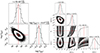 |
Fig. A.1. Corner plots for partial mass models: gas-only model (left) and stars-only model (right). See Section 5 for details. |
 |
Fig. A.2. Corner plots for complete mass models: baryons-only model (left) and baryons-plus-DM model (right). See Section 5 for details. |
The four corner plots correspond to the different mass models presented in Section 5, having an increasing number of mass components and free parameters. In addition, we show in Fig. A.3 a mass models where the stellar component is divided up in a thick exponential disk and spherical De Vaucouleurs’ bulge. In general, the posterior probability distributions are well-behaved and show clear peaks, indicating that the fitting quantities are well measured. The only exception is represented by the effective radius of the stellar spheroid (Re) which is poorly constrained in all models, so it should be interpreted as a fiducial upper limit.
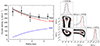 |
Fig. A.3. Left: A mass model where the stellar component is composed of an exponential disk (blue dashed line) and a De Vaucouleurs bulge (red dash-dotted line). The black dots with error bars show the observed circular velocities, while the black line shows the best-fit mass model. This model gives a total stellar mass (bulge plus disk) of |

All Tables
All Figures
|
Fig. 1. ALMA band 6 continuum map (background color map and solid gray contours) overlaid with the ATCA 18 GHz continuum map (dashed black contours). The axis coordinates are relative to the kinematic center (white star). The synthesized beams of the ALMA and the ATCA observations are shown in the bottom left and the bottom right corners, respectively. The contours in the ALMA map are at S/N = 3 × (1, 2, 4), and those in the ATCA map are at S/N = 3 × (1, 2, 4, 8, 16, 32). |
| In the text | |
|
Fig. 2. Maps of dust-only continuum emission (top left), [C I] (2−1) integrated-intensity (moment-0, top right), intensity-weighted velocity (moment-1, bottom left), and intensity-weighted line broadening (moment-2, bottom right). The axis coordinates are relative to the kinematic center (white star). The synthesized beams are shown in the lower left corner of each panel. In the dust-only continuum map, the contours correspond to S/N = 3 × (1, 2, 4). The RMS noise of the dust continuum is ∼0.012 mJy beam−1. In the moment-0 map, the contours correspond to S/N = 3 × (1, 2, 4). The S/N is calculated by 3DBAROLO, which follows the procedure in Lelli et al. (2014). In the moment-1 map, the dashed black contours show a line-of-sight velocity of ±50, ±100, and ±200 km s−1 with respect to the systemic velocity (set to zero; solid black contour). The dashed black line represents the kinematic major axis. In the moment-2 map, the contours are the same as in the moment-0 map. |
| In the text | |
|
Fig. 3. Radial surface brightness profiles of [C I] (2−1) (top, green diamonds) and dust continuum (bottom, red squares). The random error of each data point is ≲6%. The dashed black lines show Sérsic fits to each profile. |
| In the text | |
|
Fig. 4. Rotation velocity and velocity dispersion of the [C I] (2−1) disk by fitting the approaching side (blue crosses), the receding side (red diamonds), and both sides (green dots). The green band is centered at the median σv = 47 km s−1 from the two-side fitting and has a half-width of 16 km s−1, representing the uncertainty of σv (see Section 4.2). |
| In the text | |
|
Fig. 5. Position-velocity diagram along the kinematic major axis. The systemic velocity of the rotating disk is set at VLOS = 0 km s−1. The color scale and the blue contours show the observed [C I] (2−1) data. The red contours and yellow dots show the best-fit rotating disk model and the rotation velocity projected along the line of sight, respectively, assuming a constant velocity dispersion (σv = 47 km s−1). The contour levels are at S/N = ( ± 2, 3, 5), and negative contours are shown with dashed gray lines. |
| In the text | |
|
Fig. 6. Circular-velocity curve of PKS 0529–549 after correcting for pressure support. The black dots with error bars show the observed rotation velocity from 3DFIT. The red squares and the blue diamonds show the circular velocities after asymmetric drift correction assuming a constant σv and a radially varying σv, respectively. |
| In the text | |
|
Fig. 7. Channel maps of the [C I] (2−1) cube, showing every other channel. The grayscale and the blue contours show the observed [C I] (2−1) data. The red contours show the best-fit rotating-disk model (Section 4). The contour levels are at S/N = ( ± 2, 3, 5), and negative contours are shown with dashed gray lines. The axis coordinates are relative to the kinematic center (golden star). The line-of-sight velocities are relative to the redshift of the [C I] (2−1) line. The synthesized beam of the [C I] (2−1) cube is shown in the bottom left corner of each panel. |
| In the text | |
|
Fig. 8. Non-circular motions of PKS 0529–549. Left: Residual [C I] (2−1) map obtained by subtracting the best-fit rotating-disk model from the observed moment-0 map. The synthesized beam of the [C I] data is shown in the lower left corner. The axis coordinates are relative to the kinematic center (white star). The dashed circles show the aperture for measuring the flux of the enclosed structures. The black contours correspond to S/N = 3 × (1, 2, 3) of the residual map. The dashed blue arrow indicates the path for extracting the PV diagram on the right. The upper left end of the arrow indicates the width of the path. The dotted blue ticks indicate offsets of 0.0 arcsec, 0.5 arcsec, 1.0 arcsec, and 1.5 arcsec along the path. Right: Position-velocity diagram along the path on the left. The color-coding and the contour levels are the same as those in Fig. 5. |
| In the text | |
|
Fig. 9. [C I] (2−1) Renzograms (red and blue contours) overlaid on the dust-only continuum map (grayscale and dotted gray contours). The blue and red contours show narrow [C I] (2−1) moment-0 maps integrated within LoS velocities from −191 to −88 km s−1 and 274 to 377 km s−1, respectively. The contour levels are at S/N = (2, 3, 5). A single contour at S/N = 2 of the dust continuum is also shown. The synthesized beam of the dust continuum is shown in the lower left corner. |
| In the text | |
|
Fig. 10. Partial mass models: Gas only (left panel) and stars only (right panel). The black dots with error bars show the observed circular velocities in both panels. The gravitational contributions from gas and stars are shown with a dotted green line and a dashed brown line, respectively. |
| In the text | |
|
Fig. 11. Complete mass models: Baryons only (left panel) and baryons+DM (right panel). The black dots with error bars show the observed circular velocities in both panels, while the black line shows the best-fit mass model. The gravitational contribution from gas, stars, and DM are shown with a dotted green line, a dashed brown line, and a dash-dotted purple line, respectively. |
| In the text | |
|
Fig. 12. Comparison of the ALMA, VLT/SINFONI, and VLT/X-Shooter data (see also Lelli et al. 2018). Left: [C I] (2−1) (solid green) and [O III] λ5007 (dashed red) line profiles extracted from an aperture with a diameter of 1 arcsec, centered at the kinematic center. The He IIλ1640 (dash-dotted violet) line is adapted from Man et al. (2019). The velocities of [C I] (2−1), [O III] λ5007, and He IIλ1640 are relative to the redshift of [C I] (2−1) line (z = 2.5706 ± 0.0002). The CO (7−6) emission adjacent to [C I] (2−1) is marked with a dotted green line (not shifted in velocity). Right: [O III] velocity field (adapted from Nesvadba et al. 2017; Lelli et al. 2018) overlaid with the radio lobes from ATCA 18 GHz (black contours). The line-of-sight velocities are shown with respect to the redshift of [C I] (2−1). The kinematic major axes of the [C I] (2−1) and [O III] λ5007 lines are shown by the dashed green and the dash-dotted red lines, respectively. The FWHM of the SINFONI point-spread function (0.7 arcsec × 0.6 arcsec) is shown in the bottom left corner. The axis coordinates are relative to the kinematic center (white star). |
| In the text | |
|
Fig. A.1. Corner plots for partial mass models: gas-only model (left) and stars-only model (right). See Section 5 for details. |
| In the text | |
|
Fig. A.2. Corner plots for complete mass models: baryons-only model (left) and baryons-plus-DM model (right). See Section 5 for details. |
| In the text | |
|
Fig. A.3. Left: A mass model where the stellar component is composed of an exponential disk (blue dashed line) and a De Vaucouleurs bulge (red dash-dotted line). The black dots with error bars show the observed circular velocities, while the black line shows the best-fit mass model. This model gives a total stellar mass (bulge plus disk) of |
| In the text | |
Current usage metrics show cumulative count of Article Views (full-text article views including HTML views, PDF and ePub downloads, according to the available data) and Abstracts Views on Vision4Press platform.
Data correspond to usage on the plateform after 2015. The current usage metrics is available 48-96 hours after online publication and is updated daily on week days.
Initial download of the metrics may take a while.