| Issue |
A&A
Volume 691, November 2024
|
|
|---|---|---|
| Article Number | A277 | |
| Number of page(s) | 22 | |
| Section | Galactic structure, stellar clusters and populations | |
| DOI | https://doi.org/10.1051/0004-6361/202451743 | |
| Published online | 19 November 2024 | |
First measurement of the triaxiality of the inner dark matter halo of the Milky Way
Kapteyn Astronomical Institute, University of Groningen,
Landleven 12,
9747
AD
Groningen,
The Netherlands
★ Corresponding author; This email address is being protected from spambots. You need JavaScript enabled to view it.
Received:
31
July
2024
Accepted:
1
October
2024
Abstract
Context. Stellar streams are particularly sensitive probes of the mass distribution of galaxies.
Aims. In this work, we focus on the Helmi streams (HS), the remnants of an accreted dwarf galaxy orbiting the inner Milky Way. We examined their peculiar dynamical properties in depth, and used these to provide tight constraints on the Galactic potential, and specifically on its dark matter halo in the inner 20 kpc.
Methods. We extracted 6D phase-space information for the HS from Gaia DR3, and confirm that the streams split up into two clumps in angular momentum space, and that these depict different degrees of phase mixing. To explain these characteristics we explored a range of Galactic potential models with a triaxial NFW halo, further constrained by rotation curve data.
Results. We find that a Galactic potential with a mildly triaxial dark matter halo, with p = 1.013−0.006+0.006, q = 1.204−0.036+0.032, Mdiscs = 4.65−0.057+0.047⋅1010 M⊙ and MDM(< 15kpc) = 1.14−0.10+0.11 ⋅ 1111M⊙,is required to form two clumps in angular momentum space over time. Their formation is driven by the fact that the clumps are on different orbital families and close to an orbital resonance. This resonance also explains the different degrees of mixing observed, as well as the presence of a dynamically cold subclump (also known as S2).
Conclusions. This first and very precise measurement of the triaxiality of the inner dark matter halo of the Galaxy uniquely reveals the high sensitivity of phase mixed streams to the exact form of the gravitational potential.
Key words: stars: kinematics and dynamics / Galaxy: halo / Galaxy: kinematics and dynamics
© The Authors 2024
 Open Access article, published by EDP Sciences, under the terms of the Creative Commons Attribution License (https://creativecommons.org/licenses/by/4.0), which permits unrestricted use, distribution, and reproduction in any medium, provided the original work is properly cited.
This article is published in open access under the Subscribe to Open model. This email address is being protected from spambots. You need JavaScript enabled to view it. to support open access publication.
1 Introduction
Structure formation is hierarchical in the Lambda cold dark matter (ΛCDM) cosmological model, with CDM halos predominantly growing via mergers (for example White & Rees 1978). For Milky Way (MW)-like galaxies, this usually involves a small number of major mergers at early times and many minor mergers throughout their history (for example Cooper et al. 2010; Fattahi et al. 2020). While in CDM only simulations dark matter (DM) halos have triaxial shapes (Frenk et al. 1988; Springel et al. 2004), in hydrodynamical simulations including baryonic physics the DM halos tend to be rounder due to presence of baryons (Chua et al. 2019; Prada et al. 2019). In general DM halos are more spherical in the inner regions and are found to have radially varying shapes (Zavala & Frenk 2019; Shao et al. 2021). Further, the evolution of a DM halo’s shape is influenced by its merger history and its mode of accretion (Vera-Ciro et al. 2011; Cataldi et al. 2021), and also by the fundamental nature of the DM particle (Vargya et al. 2022).
The merger history of the MW has been studied in detail over the past decades, starting with the discovery of the Sagittarius dwarf galaxy (Ibata et al. 1994) and its tidal tails (Yanny et al. 2000; Ivezić et al. 2000), and the discovery of the nearby Helmi streams (HS, Helmi et al. 1999). By now, we have established a picture of the MW’s merger history which seems to have been rather quiescent. The advent of Gaia DR2 revealed that the last major merger of the MW happened about 10 Gyr ago with the massive dwarf galaxy Gaia-Enceladus-Sausage (GES, Helmi et al. 2018; Belokurov et al. 2018). The debris of a range of smaller dwarf galaxies has also been found in the inner Galactic halo (for example Koppelman et al. 2019a; Myeong et al. 2019; Naidu et al. 2020; Forbes 2020; Horta et al. 2021; Dodd et al. 2023). These accreted dwarf galaxies also bring in their own globular clusters and possibly satellite galaxies (Massari et al. 2019; Kruijssen et al. 2019; Horta et al. 2020; Callingham et al. 2022; Malhan et al. 2022). Furthermore, more than 100 thin stellar streams have been discovered so far (Carlberg 2018; Bonaca et al. 2021; Mateu 2023; Malhan et al. 2022).
Such narrow distant stellar streams have been used to study the mass distribution of our Galaxy and particularly the shape of its DM halo. Examples include the modelling of GD-1 (Koposov et al. 2010; Bovy et al. 2016), the disrupting Palomar 5 (Küpper et al. 2015), and the Sagittarius Stream (Law & Majewski 2010; Vera-Ciro & Helmi 2013; Vasiliev & Belokurov 2020). In recent years it has become clear that the determination of the shape of our DM halo is further complicated by the perturbations from, for example, the Large Magellanic Cloud (LMC, for example Vasiliev et al. 2021; Vasiliev 2024).
Some authors have recently pointed out that non-integrability of the Galactic potential can also leave imprints on the morphology and dynamics of streams, especially on streams near or on separatrices, the transitions between orbit families (Price-Whelan et al. 2016; Mestre et al. 2020; Yavetz et al. 2021, 2023). Such streams provide us with a direct probe of the location of resonances, chaotic regions, and the orbital families that are present in a gravitational system. These depend both on the characteristic parameters of the gravitational potential, such as the halo flattening, halo scale radius, or disc mass (Caranicolas & Zotos 2010; Zotos 2014), and also on the distribution function (Valluri et al. 2012).
For this work, we used the detailed dynamics of the HS to constrain the MW’s gravitational potential, and in particular the shape of its DM halo. The HS, the first substructure ever identified to occupy the inner Galactic halo (Helmi et al. 1999), are the remnants of an accreted dwarf galaxy. Follow-up studies over the past 25 years, starting with Chiba & Beers (2000), have created a picture of the history and characteristics of the streams (see also Kepley et al. 2007; Smith et al. 2009). The parent dwarf galaxy is thought to have a mass of about 108 M⊙ and to have been accreted 5–10 Gyr ago (Kepley et al. 2007; Koppelman et al. 2019b; Naidu et al. 2022; Ruiz-Lara et al. 2022a). The HS’ stars show abundance patterns that are distinct from other substructures (Aguado et al. 2021; Nissen et al. 2021; Matsuno et al. 2022; Horta et al. 2023; Zhang et al. 2024). Between 7 and 15 GC are thought to be associated with it (Koppelman et al. 2019b; Massari et al. 2019; Kruijssen et al. 2020; Forbes 2020; Callingham et al. 2022). As was noted by Helmi (2020), it seems curious that such a low mass galaxy would have been accreted to the inner halo at z < 1 and is now orbiting the inner MW. Possible mechanisms could involve group infall, but as we shall demonstrate below, this might not be necessary and a purely dynamical explanation is likely.
Dodd et al. (2022) found that the HS split into two clumps in angular momentum space which are chemically indistinguishable, supporting a common origin. One of the clumps was found to exhibit a kinematically cold subclump (Myeong et al. 2018; Dodd et al. 2022) Later, the two clumps were recovered using a single-linkage clustering algorithm in Gaia EDR3 (Lövdal et al. 2022; Ruiz-Lara et al. 2022b) and Gaia DR3 data (Dodd et al. 2023), with a gap identified in between as an underdensity. Dodd et al. (2022) used the existence of the gap to constrain the flattening of the DM halo density to be qρ = 1.2. In such a potential, the gap is long-lasting as the effective gravitational potential (provided by the sum of all mass components) is close to being spherical, and one of the clumps is on an orbital resonance. This, however, does not explain how the two clumps were formed, which is the question this paper subsequently addresses. We did this by inspecting the orbital structure in the region of phase space occupied by the streams for a range of Galactic potential models with a triaxial DM halo.
This paper is structured as follows. Sect. 2 discusses the data and the methods used in this paper, which involves the application of a chaos indicator, the study of orbit families, and orbital frequency analysis. In Sect. 3 we present our analysis of the orbital properties of the HS in a range of triaxial potentials. This leads to a method to constrain the Galactic potential in the region probed by the streams, and in particular the shape of the inner DM halo. In Sect. 4 we discuss the results of this analysis. We end with a general discussion in Sect. 5 and present our conclusions in Sect. 6.
2 Data and method
2.1 Generalities
We use the HS sample of Dodd et al. (2023), which was constructed by applying a single-linkage clustering algorithm (see also Lövdal et al. 2022; Ruiz-Lara et al. 2022b) on the Gaia DR3 (Gaia Collaboration 2023) RVS sample for a selection of halo stars in a local volume of 2.5 kpc. This sample consists of 319 members with distance errors <20%. The distances to the stars were obtained by inverting their parallaxes after correcting these for a zeropoint offset following Lindegren et al. (2021).
To convert to Galactocentric Cartesian and cylindrical coordinates1, we followed the assumptions of Eilers et al. (2019) and Zhou et al. (2023), as we use their rotation curve data later in this work, which requires consistency. Hence, we assumed a height above the midplane of z⊙ = 0.025 kpc (Jurić et al. 2008) and a distance from the Sun to the Galactic Centre of R⊙ = 8.122 kpc (GRAVITY Collaboration 2018), which is consistent with more recent measurements of orbits around Sgr A* (Do et al. 2019; GRAVITY Collaboration 2021) and other dynamical measurements (for example Leung et al. 2023). To correct for the motion of we Sun, we used the proper motion of Sgr A* by (Reid & Brunthaler 2004), μ1,Sgr A* = −6.379 ± 0.026 mas yr−1, μb,Sgr A* = −0.202 ± 0.019 mas yr−1, and the relation that
![Mathematical equation: $\[v_{j}=4.74057 \mathrm{~km} \mathrm{~s}^{-1}\left(\frac{\mu_{j}}{{\mathrm{mas} ~\mathrm{yr}^{-1}}}\right)\left(\frac{d}{\mathrm{kpc}}\right),\]$](/articles/aa/full_html/2024/11/aa51743-24/aa51743-24-eq3.png) (1)
(1)
where j = (l, b) in this case. This gives vy,⊙ = 245.6 km s−1 and W⊙ = vz,⊙ = 7.8 km s−1. We assumed U⊙ = vx,⊙ = 11.1 km s−1 (Schönrich et al. 2010), which is consistent with a range of more recent estimates (Tian et al. 2015; Mróz et al. 2019; Zbinden & Saha 2019). The z component of the angular momentum vector, Lz, is defined such that it is positive for prograde orbits, that is, its sign is flipped.
We used AGAMA (Vasiliev 2019) for orbit integration and to compute dynamical quantities. Our fiducial MW model follows the McMillan (2017) potential with some modifications. The McMillan (2017) axisymmetric potential model consists of a bulge, an exponential thin and thick disc, an HI gas disc, a molecular gas disc, and a spherical NFW DM halo. Instead of the 3 kpc of the original model, in this work, we set a thick disc scale length of Rthick = 2 kpc2. We also assumed a prolate DM halo with a flattening in the density of qρ = 1.2, following Dodd et al. (2022). To constrain the mass of the stellar discs, and the DM halo scale radius and density in this new fiducial model, we used recent rotation curve data with associated uncertainties derived using axisymmetric Jeans equations by Eilers et al. (2019) and Zhou et al. (2023). The procedure followed to determine the values of the characteristic parameters is described in detail in Appendix A. The resulting rotation curve and a comparison to other models from literature is shown in Fig. 1. Our fiducial model has a total mass within 20 kpc of ![Mathematical equation: $\[M_{\mathrm{tot}}(r<20 ~\mathrm{kpc})= 2.2_{-0.1}^{+0.1} \cdot 10^{11} ~M_{\odot}\]$](/articles/aa/full_html/2024/11/aa51743-24/aa51743-24-eq4.png) , compatible with other estimates (for example Küpper et al. 2015; Posti & Helmi 2019; Watkins et al. 2019; Eadie & Jurić 2019), and vc(R⊙) = 233.2 ± 2.6 km s−1. Consequently, our V⊙ = vy,⊙ − vLSR = 12.4 km s−1, well in agreement with for example the work by Tian et al. (2015), Zbinden & Saha (2019) or the commonly used value found by Schönrich et al. (2010).
, compatible with other estimates (for example Küpper et al. 2015; Posti & Helmi 2019; Watkins et al. 2019; Eadie & Jurić 2019), and vc(R⊙) = 233.2 ± 2.6 km s−1. Consequently, our V⊙ = vy,⊙ − vLSR = 12.4 km s−1, well in agreement with for example the work by Tian et al. (2015), Zbinden & Saha (2019) or the commonly used value found by Schönrich et al. (2010).
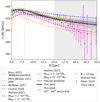 |
Fig. 1 Rotation curves of a variety of MW mass models. We have plotted here the models by Bovy (2015), Price-Whelan (2017), McMillan (2017), and Cautun et al. (2020), and two models by Vasiliev (2024) using his ℒ3, ℳ11 and ℒ2, ℳ11 halo models at the present day. The grey line shows the rotation curve of the fiducial model (described in Sect. 2.1 and Appendix A). The black line shows the best-fit potential of this work (described in Sect. 4.2), while the grey shaded area correspond to the 16th to 84th percentile range for 200 potentials from the MCMC chains. The rotation curve data used in the fit includes Eilers et al. (2019)’s rotation curve data, shown in magenta, and Zhou et al. (2023)’s in yellow. The light grey shaded area marks the region R > 15 kpc and data in this distance range was not included in the MCMC fit. However, the fit is similar even if data up to R ~ 20 kpc is used. |
2.2 Review of dynamics
Integrals of motion (IoM) are quantities that only depend on a body’s phase-space coordinates and are constant along an orbit. In a time independent potential, the total energy E = Ekin + Epot is an IoM. In a spherical potential, all components of the angular momentum vector, L = r × p = (Lx, Ly, Lz), are IoM, and hence so is the perpendicular angular momentum vector component, ![Mathematical equation: $\[L_{\perp}^{2}=L_{x}^{2}+L_{y}^{2}\]$](/articles/aa/full_html/2024/11/aa51743-24/aa51743-24-eq5.png) . In an axisymmetric potential, symmetry with the polar angle θ is broken and therefore only Lz = Rvϕ remains an IoM, though L⊥ is sometimes used to characterise orbits (as a proxy for a third integral). In a triaxial potential, also symmetry with respect to the azimuthal angle ϕ is broken and none of the components of the angular momentum vector are IoM.
. In an axisymmetric potential, symmetry with the polar angle θ is broken and therefore only Lz = Rvϕ remains an IoM, though L⊥ is sometimes used to characterise orbits (as a proxy for a third integral). In a triaxial potential, also symmetry with respect to the azimuthal angle ϕ is broken and none of the components of the angular momentum vector are IoM.
A regular orbit is quasi-periodic, and the time series of its phase space coordinates w(t) = (x(t), v(t)) can approximated by the sum
![Mathematical equation: $\[w(t)=\sum_{k}^{\infty} a_{k} e^{i \omega_{k} t},\]$](/articles/aa/full_html/2024/11/aa51743-24/aa51743-24-eq6.png) (2)
(2)
where ωk are orbital frequencies and ak the associated amplitudes. Therefore, a Fourier transform of the orbit gives us a spectrum with peaks at ωk of amplitude ak. A regular orbit can be described by its three independent fundamental frequencies, meaning that all other peaks ωk in the spectrum are a linear combination of those, ωk = nk ⋅ Ω, with n is a vector of three integers. If the fundamental frequencies are commensurable, that is, one is a ratio of small integers of the other, n ⋅ Ω = 0, the orbit is said to be resonant. A singly resonant orbit is confined to a two-dimensional surface, while a doubly resonant orbit traces a closed one-dimensional curve. A sufficiently tight ensemble of particles can be resonantly trapped by a resonant orbit, meaning that their orbits have a finite libration amplitude around the resonance (Binney & Tremaine 2008). Depending on how strongly trapped the particles are, and thus how small the libration amplitude is, they will occupy a subspace of phase-space around the resonant orbit. While an ensemble of particles on regular nonresonant orbits phase mixes at a rate ∝ t−3, where t is time, an ensemble of particles trapped by a resonant orbit phase mixes slower, at a rate ∝ t−2 for a singly resonant orbit and at a rate ∝ t−1 for a doubly resonant orbit (Vogelsberger et al. 2008).
At the edge of a family of resonant orbits we find a separatrix, which denotes a transition between orbit families. A separatrix is a stochastic region3 hosting chaotic orbits. Such orbits are not quasi-periodic and do not have three IoM. Substructures on chaotic orbits therefore diffuse and mix faster than substructures on regular orbits (Price-Whelan et al. 2016; Mestre et al. 2020). Moreover, stellar streams on separatrices can exhibit unusual morphologies and similarly undergo faster diffusion (Yavetz et al. 2021, 2023). Naturally, triaxial potentials host a wider range of orbits, and consequently more separatrices and more chaotic orbits than an axisymmetric potential (Papaphilippou & Laskar 1998; Binney & Tremaine 2008). However, also axisymmetric potentials can host chaotic orbits (Zotos & Carpintero 2013; Zotos 2014), including simple models such as the Miyamoto Nagai potential (Pascale et al. 2022). The location of chaotic regions, resonances, separatrices, and different orbit families can be analysed using for example the orbital frequencies (Valluri et al. 2012), and these of course depend on a potential’s characteristics (Caranicolas & Zotos 2010; Zotos 2014).
2.3 Characterising the Helmi streams
Figure 2 shows the distribution of the HS stars in IoM (E, Lz, L⊥), velocity, and configuration space. The top-left panel shows that the HS separate in two clumps in (Lz, L⊥) space, as first identified by Dodd et al. (2022). We empirically separated the sample into the hiL clump, having larger L⊥, and loL clump, having lower L⊥, and classify a star with a given L⊥,* and Lz,* as follows
![Mathematical equation: $\[L_{\perp, *} \begin{cases}>0.35 \cdot L_{z, *}+1525 \mathrm{~kpc} \mathrm{~km} \mathrm{~s}^{-1} & \rightarrow \text { hiL clump }\\ <0.35 \cdot L_{z, *}+1525 \mathrm{~kpc} \mathrm{~km} \mathrm{~s}^{-1} & \rightarrow \text { loL clump },\end{cases}\]$](/articles/aa/full_html/2024/11/aa51743-24/aa51743-24-eq7.png) (3)
(3)
see also Fig. 2. There are 191 and 128 stars in the hiL and loL clumps (respectively)4. The median position of the hiL stars is (Lz, L⊥) = (1234, 2207) kpc km s−1, while the median position of the loL stars is (Lz, L⊥) = (1436, 1791) kpc km s−1. We confirmed that these two clumps have consistent stellar populations and metallicity distributions, with a median metallicity of −1.45 dex and standard deviation of 0.42 dex using LAMOST LRS DR7 metallicity estimates (Zhao et al. 2012).
The lower left panel of Fig. 2, displaying the (E, L⊥) distribution, shows that on average the hiL stars are less bound and the loL stars span a larger range in energy. The hiL stars have larger apocentres and reach higher above the midplane, see also Fig. 3. This is robust for different Galactic potential models, though of course the exact apo- and pericentre distribution changes.
The two middle panels of Fig. 2 show the velocity distribution of the two clumps. Interestingly, the ratio of stars with positive vz, to negative vz differs between the two clumps. For the hiL clump this ratio is ![Mathematical equation: $\[\frac{N_{\mathrm{hiL}}\left(v_{z}^{+}\right)}{N_{\text {hiL }}\left(v_{z}^{-}\right)}=\frac{13}{178} \sim 0.07\]$](/articles/aa/full_html/2024/11/aa51743-24/aa51743-24-eq8.png) , while for the loL clump this ratio is
, while for the loL clump this ratio is ![Mathematical equation: $\[\frac{N_{\text {loL }}\left(v_{z}^{+}\right)}{N_{\text {loL }}\left(v_{z}^{-}\right)}=\frac{49}{79} \sim 0.62\]$](/articles/aa/full_html/2024/11/aa51743-24/aa51743-24-eq9.png) . In earlier work, the bimodality in vz of the entire HS has been used to obtain a rough estimate for the time of accretion (Kepley et al. 2007; Koppelman et al. 2019b), since it is an indication of a structure’s degree of phase mixing. The hiL clump not only appears to be less phase mixed, but it forms a tighter, more coherent structure in velocity space than the loL clump stars. The hiL clump even exhibits a kinematically cold subclump (in black in Figs. 2 and 3), and defines a stream-like structure in configuration space, as the two right panels of Fig. 2 show.
. In earlier work, the bimodality in vz of the entire HS has been used to obtain a rough estimate for the time of accretion (Kepley et al. 2007; Koppelman et al. 2019b), since it is an indication of a structure’s degree of phase mixing. The hiL clump not only appears to be less phase mixed, but it forms a tighter, more coherent structure in velocity space than the loL clump stars. The hiL clump even exhibits a kinematically cold subclump (in black in Figs. 2 and 3), and defines a stream-like structure in configuration space, as the two right panels of Fig. 2 show.
We selected the subclump as 1320 ≤ Lz ≤ 1410 kpc km s−1, 2330 ≤ L⊥ ≤ 2500 kpc km s−1, and x > −9.2 kpc and found 9 members. Four of these stars have LAMOST LRS DR7 metallicity estimates (Zhao et al. 2012), which are [Fe/H] = −1.77, −2.04, −1.48 and −2.19 dex, with typical uncertainties of 0.1 dex (Anguiano et al. 2018; Niu et al. 2023) to ~0.3 dex at the metal-poor end (Li et al. 2018). Given these uncertainties and the metallicity distribution of the HS, the subclump is indistinguishable from the HS in its stellar populations. Although this may apparently contrast Myeong et al. (2018)’ ‘independent’ identification of the subclump in Gaia DR2, naming it S2, subsequent high-resolution spectroscopic follow-up of S2 by Aguado et al. (2021) also support the association. This has been convincingly demonstrated by Matsuno et al. (2022) who studied the abundance patterns of a sample of HS stars and homogeneously reanalysed the spectra of three Aguado et al. (2021) stars and concluded that their abundance patterns are fully consistent. Similarly, Dodd et al. (2022) identified and considers the subclump as a part of the HS. Given its much tighter distribution, the subclump must have evolved dynamically more slowly than the rest of the substructure, as it is significantly less phase mixed. This could happen if the dynamical evolution of the subclump is affected by a resonance.
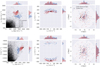 |
Fig. 2 Distribution of the HS in IoM-space defined as E, Lz, and L⊥ (left), velocity (middle), and configuration space (right) separated in the hiL clump (red, 191 stars in total) and loL clump (blue, 128 stars in total) based on the stars’ position in (Lz, L⊥) space, see top-left panel. The subclump, a kinematically cold, coherent group of stars, is indicated in black. The stars in the background of the energy and angular momentum distributions correspond to the selection of local halo stars (d < 2.5 kpc) by Dodd et al. (2023). The energy values have been computed in the fiducial potential (see Appendix A). Histograms on the top and right of each plot show the one-dimensional distributions. The error bars on the data points denote the uncertainties. The hiL clump has on average lower Lz, higher L⊥, higher energy, larger |vz| and lower vy. |
2.4 Orbital characterisation: Frequency analysis and chaos indicators
In cylindrical coordinates, we typically use three orbital frequencies (ΩR, Ωϕ, Ωz) which are related to the orbit’s oscillation in the radial, vertical, and azimuthal directions. For a regular orbit, the components of its frequency spectrum are linear integer combinations of the three orbital frequencies (ΩR, Ωϕ, Ωz)5. For a resonant orbit, two or more frequencies are commensurate, while for a chaotic orbit the orbital frequencies vary with time. To determine the orbital frequencies corresponding to a star’s orbit, we use a modified version of SuperFreq (Price-Whelan 2015), as described in detail in Appendix B.
In contrast to regular orbits, a chaotic orbit has less than 3 integrals of motion, and as a consequence it undergoes orbital diffusion. Therefore, if the MW’s potential hosts a stochastic region in between the two HS clumps, this could possibly lead to a depletion of stars in that region. To identify chaotic behaviour, we make use of the Lyapunov exponent Λ. Take an orbit x(t) and an orbit infinitely close to it, x(t) + w(t). Here, w(t) is the socalled deviation vector, which grows as a power-law in time for a regular orbit, but exponential in time for a chaotic orbit. The Lyapunov exponent Λ measures the time variation of w(t),
![Mathematical equation: $\[\Lambda \equiv \lim _{t \rightarrow \infty} \frac{\ln |\boldsymbol{w}|}{t}.\]$](/articles/aa/full_html/2024/11/aa51743-24/aa51743-24-eq10.png) (4)
(4)
To compute Λ, we resorted to its finite-time estimate. For a period of time where the orbit is regular, ln |w|/t fluctuates around a constant value, and in that case Λ is set to zero. When an orbit is chaotic, Λ is estimated as the average value of ln |w|/t over the period of exponential growth. Thus, the larger Λ is, the more chaotic the orbit is. The Lyapunov exponent also gives an indication of the timescale of chaoticity. In this work, the finite-time estimate of Λ was computed using AGAMA over an integration time of 100 Gyr.
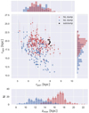 |
Fig. 3 Pericentre, apocentre, and zmax distribution of the HS’ orbits in the fiducial potential (see Appendix A). The hiL stars are indicated in red, the loL stars in blue and the subclump with black edges as in Fig. 2. Histograms on the top and right of the top plot show the one-dimensional distributions. The apocentres and pericentres were determined as the maximum and minimum distance from the Galactic Centre that the orbit reached over an integration time of 10 Gyr. An estimate for the uncertainties was obtained by randomly sampling the observables a 1000 times within their uncertainties after integrating their orbits. |
3 Analysis
3.1 The Helmi streams’ orbits in a triaxial potential
To investigate how the dynamical properties of the HS can be explained, we studied their orbits in a range of mildly triaxial potentials, and we explored the orbital structure in the region of phase space occupied by the HS. We explored triaxial potentials as, on the basis of cosmological simulations, it is likely that DM halos have a triaxial shape, particularly at larger radii (Frenk et al. 1988; Vera-Ciro et al. 2011; Cataldi et al. 2021). Moreover, there is evidence that MW’s halo is being perturbed and deformed by the infall of the Large Magellanic Cloud (LMC, Garavito-Camargo et al. 2019, 2021).
We modified the fiducial MW model based on the McMillan (2017) potential described in Sect. 2.1 (see also Appendix A) by replacing its NFW halo with a triaxial halo:
![Mathematical equation: $\[\rho_{\mathrm{NFW}}(x, y, z)=\frac{\rho_{0}}{\frac{\tilde{r}}{r_{s}}\left(1+\frac{\tilde{r}}{r_{s}}\right)^{2}},\]$](/articles/aa/full_html/2024/11/aa51743-24/aa51743-24-eq11.png) (5)
(5)
with
![Mathematical equation: $\[\tilde{r}=\sqrt{x^{2}+\frac{y^{2}}{p^{2}}+\frac{z^{2}}{q^{2}}},\]$](/articles/aa/full_html/2024/11/aa51743-24/aa51743-24-eq12.png) (6)
(6)
and where
![Mathematical equation: $\[p^{2}=\frac{b^{2}}{a^{2}}, \quad q^{2}=\frac{c^{2}}{a^{2}}.\]$](/articles/aa/full_html/2024/11/aa51743-24/aa51743-24-eq13.png) (7)
(7)
We made sure that the circular velocity at the position of the Sun is equal to vc(R⊙) = 233.2 km s−1 when varying (p, q)6. We explored the range 1.05 ≤ q ≤ 1.35 and 0.90 ≤ p ≤ 1.10, which is motivated by disc stability constraints (Prada et al. 2019; Cataldi et al. 2021) and the requirement that to maintain the gap we need an effective potential that is roughly spherical (Dodd et al. 2022). To study how varying p and q influences HS’ orbits, we integrated these for 100 Gyr and (1) computed the finite-time estimate of the Lyapunov exponent to study chaoticity, (2) we quantified the variation in Lz and Ly for each orbit to distinguish different types of orbit families, and (3) we determined the orbital frequencies ΩR, Ωϕ, and Ωz as outlined in Appendix B to identify possible orbital resonances. The average or median values of these quantities for the loL stars, hiL stars and subclump stars are shown in the left, central and right columns of Fig. 4 respectively. We discuss the behaviour of each dynamical quantity in the following paragraphs.
3.1.1 Chaoticity: The Lyapunov exponent
The average Lyapunov exponent of the hiL stars, loL stars, and subclump are shown separately in the form of a map in the top row of Fig. 4. There is a band of chaoticity (with light green-yellow corresponding to Λ ≳ 0.04) in the region q ~ 1.13, p ~ 0.90, till q ~ 1.25, p ~ 0.97 for the loL stars, while for hiL stars the chaoticity band occupies a narrower region from q ~ 1.05, p ~ 0.90 till q ~ 1.15, p ~ 0.97, and an even narrower region with chaotic behaviour is present for q ~ 1.05, p ~ 0.90, till q ~ 1.13, p ~ 0.97 for the subclump stars. The band of chaoticity is thus located at larger q for the loL stars, and it also appears broader. This is due to the loL stars occupying a larger (and different) volume in phase space than the hiL stars, see Fig. 2. Interestingly, there is no analogous chaotic region for potentials with p > 1.
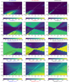 |
Fig. 4 Various dynamical quantities of the loL stars (left column) and hiL stars (middle column) and subclump stars (right column) in a potential with a triaxial halo with a range of p and q as calculated by AGAMA for an integration time of 100 Gyr. The grey horizontal line at p = 1 serves to guide the eye and indicates axisymmetric potentials. The white dotted line indicates the Ωϕ : Ωz = 1:1 resonance (see also bottom row). Top row: average Lyapunov exponent. A non-zero Lyapunov exponent indicates that there is chaoticity. The overlaid black contours, which are also shown in the other rows, map average(Λ*) at the levels of 0.02 and 0.04, as is also indicated on the colourbar. Second row: median variation in Lz, with ΔLz,* = max(Lz,*) − min(Lz,*) over the entire integration time. Third row: median variation in Ly, with ΔLy,* = max(Ly,*) − min(Ly,*) over the entire integration time. Bottom row: median(Ωϕ : Ωz) ratio. We can see clear correspondences between the four different rows. The chaotic regions overlap with the median(Ωϕ : Ωz) = 1:1 resonance and a transition in the value of ΔLz and ΔLy. This transition indicates a change in orbit family, and the text in the middle column indicates where the different orbit families reside, of which examples are shown in Fig. 5 (the crosses in this figure indicate their p and q). To the left of the chaotic band we find z-tube orbits, which have an oscillating Ly and a roughly conserved Lz, such that median(ΔLy) ≲ 4000 kpc km s−1, median(ΔLz) ≲ 500 kpc km s−1. To the right of the chaotic band we find y-tube orbits, which have a roughly conserved Ly and an oscillating Lz, such that median(ΔLy) ~ 1000 kpc km s−1 and median(Δ Lz) ~ 3000 kpc km s−1. For p > 1, the Ωϕ:Ωz = 1:1 is a resonance that traps orbits, which reduces their variation in both Ly and Lz. This is most clear for the subclump stars. |
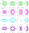 |
Fig. 5 Orbits integrated for 25 Gyr for a randomly selected hiL star in different triaxial potentials. Top row: p = 0.97, q = 1.08, resulting in a z-tube orbit(green). Second row: a y-tube orbit for p = 1.05, q = 1.11 (pink). Third row: a resonant orbit for p = 1.05, q = 1.245 (cyan). Bottom row: a chaotic orbit with Λ = 0.12 for p = 0.83, q = 0.977888. |
3.1.2 y-tube and z-tube orbits and variations in Lz and Ly
We can get more insight into what causes the band of chaoticity by inspecting the orbits of the HS stars in the different potentials, of which examples are shown in Fig. 5 (see also Appendix C). The tube orbit family comprises regular orbits which fill a doughnut-like shaped volume in configuration space. Tube orbits have a sense of rotation around the principal axes of the potential, and depending on which axis they are called short- or inner/outer long axis tube orbits (see also Binney & Tremaine 2008). As we vary p and q, the long and short axis swap orientation7. Therefore, we choose a more general naming convention and define the z-axis tube orbits (z-tube orbits) as rotating around the z-axis, while the y-axis tube orbits (y-tube orbits) are defined as rotating around the y-axis. Tube orbits are centrophobic, that is, they do not pass through the centre of the potential, which results in a non-zero time-averaged angular momentum about whichever axis they rotate. This can also be appreciated from Figs. 5 and 6, which shows that the z-tube orbit rotates around the z-axis, keeping its Lz roughly conserved in time, while its Ly varies by a large amount with a time-average equal to zero. On the other hand, the y-tube orbit revolves around the y-axis, keeping its Ly roughly conserved, while its Lz varies by a large amount with a time-average equal to zero.
A way to differentiate between these two orbit families is thus by inspecting the orbit’s variation in Lz and Ly, which we define as
![Mathematical equation: $\[\Delta L_{i}=\max (L_{i})-\min (L_{i})\]$](/articles/aa/full_html/2024/11/aa51743-24/aa51743-24-eq14.png) (8)
(8)
where i refers to the component of the angular momentum, in this case y or z, and ΔLi is calculated over at least one period in angular momentum space (for example the period of the z-tube orbit shown in Fig. 6 is about 25 Gyr). Figure 6 illustrates the expected range of variation in Ly and Lz : the z-tube orbit has ΔLz ≈ 500 kpc km s−1 and ΔLy ≈ 4500 kpc km s−1, while the y-tube orbit has ΔLz ≈ 3000 kpc km s−1 and ΔLy ≈ 500 kpc km s−1. The bottom row of Fig. 5 shows a chaotic orbit without a third IoM which has ΔLz ≈ ΔLy ≈ 4500 kpc km s−1.
The second row of Fig. 4 shows a map of the median(ΔLz) for the hiL stars and loL stars for different p and q, while the third row of Fig. 4 shows the median(ΔLy). These maps clearly show the regions occupied by the z-tube and y-tube orbits. A comparison of the top three rows of Fig. 4 reveals that the chaotic band coincides with the transition between these two orbit families. In this chaotic band, median(ΔLz) is larger, as expected. The maps also show that potentials with DM halo shapes p > 1 and p < 1 have a roughly similar behaviour and largely mirror each other, but for p > 1 there is a region with a lower median(ΔLz) that is not present in p < 1. This region corresponds to an orbital resonance that traps orbits, as we discuss in the next section.
Summarising, Fig. 4 shows that there is a part of (p, q) parameter space where the hiL stars are on y-tube orbits, while the loL stars are on z-tube orbits. This holds roughly from (p, q) = (0.9, 1.10) till (p, q) = (0.98, 1.17) and from (p, q) = (1.01, 1.20) till (p, q) = (1.10, 1.05). In such a configuration, we would expect that the hiL clump stars slowly change their Lz over time, while the loL clump’s Lz stays roughly conserved, leading to a separation of the two clumps over time. Such behaviour could therefore possibly explain the formation of two (the hiL and loL) clumps.
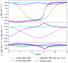 |
Fig. 6 Behaviour over time of Lz, Ly, and L⊥ for the orbits shown in Fig. 5. Since the z-tube orbits around the z-axis, it has a roughly conserved Lz and L⊥, but a time-varying Ly. Similarly, since the y-tube orbits around the y-axis, it has a roughly conserved Ly and L⊥ but a time-varying Lz. For the chaotic orbit, Lz, Ly, and L⊥ vary largely in time. The resonant orbit has a small variation in Ly, Lz, and L⊥. |
3.1.3 Orbital frequencies and resonances
To investigate further the transition in orbit family at these specific p and q, we inspected the behaviour of the orbital frequencies ΩR, Ωϕ, and Ωz. The bottom row of Fig. 4 shows a map of the ratio of Ωϕ : Ωz for the values of p and q explored in the other panels. This reveals that the change in orbit family seen in the two middle rows is related to the Ωϕ : Ωz = 1:1 resonance. For p < 1, the chaotic band neatly overlaps with the white dotted line indicating the resonance. Therefore, the chaotic behaviour seen in the top row is due to the stochastic layer around the 1:1 resonance. This happens for p < 1 because the short and long axis of the potential are exchanged: for an oblate effective potential, z is the short axis, while for p < 1 and a prolate effective potential, the short axis is y. Because of this, the 1:1 resonance works as a separatrix: stars on this resonance do not know whether to rotate around the z-axis or y-axis, as the chaotic orbit in Fig. 5 shows. This orbit seems to jump between a y tube orbit (0–10 Gyr), z-tube orbit (10–20 Gyr) and a resonantly trapped orbit (20–25 Gyr).
On the other hand, for p > 1, the region that has a lower median(ΔLz) overlaps with the 1:1 resonance, and in this case the resonance actually stabilises the orbits and resonantly traps them. These resonantly trapped orbits have angular momenta both around the z and y-directions, and orbit in a plane in (y, z), see also Fig. 5 and Appendix C (available on Zenodo). Their Ly, Lz, and L⊥ are almost constant in time, as seen in Fig. 6, indicating that in this region the effective potential is roughly spherical.
Given these findings, a picture emerges where the loL and hiL clump could be on different orbital families. This would require a potential with (p, q) values such that the hiL clump is on the y-tube orbits and the loL clump on the z-tube orbits. Furthermore, the presence of the kinematically cold subclump in the hiL clump suggests that it is associated with a stabilising orbital resonance, as present for p > 1, as this slows down phase mixing. From these considerations, it naturally follows that the subclump could be on the Ωϕ:Ωz = 1:1 resonance, while (part of) the hiL clump would be resonantly trapped by that same resonance. The loL clump would not be on the 1:1 resonance, and would phase mix at a normal rate as this would explain the asymmetries reported in Sect. 2.3 regarding the number of stars in the streams with positive and negative z-velocities. The opposite effect would occur for p < 1, as the orbits are chaotic close to the Ωϕ:Ωz = 1:1 resonance and undergo quick orbital diffusion, and a kinematically cold subclump could not be sustained. This is why p < 1 is disfavoured.
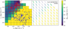 |
Fig. 7 Resonance trapping in a potential with a triaxial NFW halo with p = 1.02 and q = 1.19. The left panel depicts with different colours the variation in angular momentum, |
![Mathematical equation: $\[\Delta L_{y, z}=\sqrt{\Delta L_y^2+\Delta L_z^2}\]$](/articles/aa/full_html/2024/11/aa51743-24/aa51743-24-eq15.png)
3.1.4 Resonance trapping
We studied the effect of resonance trapping by the Ωϕ : Ωz = 1:1 resonance in more detail in Fig. 7. We integrated a set of orbits in a potential with a triaxial halo with p = 1.02 and q = 1.19, as in this potential the subclump stars are strongly resonantly trapped (see for example Appendix C). The orbits’ initial conditions were generated by varying (Lz, L⊥) on a grid and using the energy and 3D position of a subclump star. We inspected the variation in angular momentum, ![Mathematical equation: $\[\Delta L_{y, z}=\sqrt{\Delta L_y^2+\Delta L_z^2}\]$](/articles/aa/full_html/2024/11/aa51743-24/aa51743-24-eq16.png) , to quantify how strongly trapped an orbit is. Orbits on the Ωϕ:Ωz = 1:1 resonance have a roughly conserved Ly and Lz, while z-tube orbits and y-tube orbits do not conserve their Ly and Lz, respectively (see Fig. 6). Hence, a small value of ΔLy, z indicates that an orbit is resonantly trapped, allowing us to probe the extent of the resonance, as we show in Fig. 7.
, to quantify how strongly trapped an orbit is. Orbits on the Ωϕ:Ωz = 1:1 resonance have a roughly conserved Ly and Lz, while z-tube orbits and y-tube orbits do not conserve their Ly and Lz, respectively (see Fig. 6). Hence, a small value of ΔLy, z indicates that an orbit is resonantly trapped, allowing us to probe the extent of the resonance, as we show in Fig. 7.
Figure 7 shows that the resonance covers a region that is as large as the hiL clump, though not each orbit is as strongly trapped as the other. The smaller the variation in angular momentum ΔLy, z is, the more strongly resonantly trapped the orbit is, as can be seen by comparing the left and right panels of Fig. 7. The right panel shows the (y, z) projection of the orbits over an integration time of 20 Gyr, and reveals that resonant orbits define a 2D planar structure in (y, z) space.
3.1.5 The hiL and loL clump on different orbit families
To understand in which potential the individual hiL and loL clump stars are on the y-tube, z-tube or resonantly trapped orbits, we computed ΔLz and ΔLy for each individual HS star in the potentials for the range 1.00 < p < 1.04 and 1.13 < q < 1.23. Based on visual inspection of a large range of orbits, we employed the following empirical criteria based on the orbit’s ΔLz and ΔLy (see Fig. 5 and Sect. 3.1) to call them:
![Mathematical equation: $\[\text { orbit family }=\left\{\begin{array}{cc}\text { z-tubes } & \text { if }\left[\Delta L_{y}>1200 \mathrm{~kpc} \mathrm{~km} \mathrm{~s}^{-1}\right] \& \\& {\left[\Delta L_{z}<\Delta L_{y}\right]} \\\text { y-tubes } & \text { if }\left[\Delta L_{z}>1200 \mathrm{~kpc} \mathrm{~km} \mathrm{~s}^{-1}\right] \& \\& {\left[\Delta L_{z}>\Delta L_{y}\right]} \\\text { resonant } & \text { if }\left[\Delta L_{y}<400 \mathrm{~kpc} \mathrm{~km} \mathrm{~s}^{-1}\right] \& \\& {\left[\Delta L_{z}<400 \mathrm{~kpc} \mathrm{~km} \mathrm{~s}^{-1}\right]} \\\text { trapped } & \text { if }\left[\Delta L_{y}<750 \mathrm{~kpc} \mathrm{~km} \mathrm{~s}^{-1}\right] \& \\\text { (strong) } & {\left[\Delta L_{z}<750 \mathrm{~kpc} \mathrm{~km} \mathrm{~s}^{-1}\right]} \\\text { trapped } & \text { if }\left[\Delta L_{y}<1200 \mathrm{~kpc} \mathrm{~km} \mathrm{~s}^{-1}\right] \& \\& {\left[\Delta L_{z}<1200 \mathrm{~kpc} \mathrm{~km} \mathrm{~s}^{-1}\right] .}\end{array}\right.\]$](/articles/aa/full_html/2024/11/aa51743-24/aa51743-24-eq17.png) (9)
(9)
Figure 8 shows the result. For axisymmetric potentials (that is, p = 1), ΔLz is equal to zero for all stars for, as expected, but for p > 1 the stars occupy different regions of the (ΔLz, ΔLy) space, meaning they are on different orbit families. While the loL stars are mainly on z-tube orbits, meaning they largely conserve their Lz, the hiL stars are mainly resonantly trapped or are on y-tube orbits. The subclump stars are naturally also either resonantly trapped or on y-tube orbits. Hence, this figure illustrates that it is possible to have the HS stars on different orbit families in the same Galactic potential, even though they belong to the same accreted parent satellite (see also Appendix D, available on Zenodo).
Following our findings, we required the hiL stars to be on y-tube orbits, or possibly being resonantly trapped, we required the loL stars to be on the z-tube orbits, and we required the subclump to be strongly resonantly trapped on the Ωϕ:Ωz = 1:1 resonance. The percentages in Fig. 8 indicate the percentage of the hiL, loL, and subclump stars that are on the desired orbit family. The range of p and q for which the percentage of hiL stars on y-tube orbits, the percentage of loL stars on z-tube orbits, and the percentage of subclump stars on resonantly trapped orbits is larger than 50% is for (p, q) = (1.01, [1.17, 1.21]) and (p, q) = (1.02, [1.18, 1.20]). For even larger values of q, an increasing number of loL stars end up on y-tube orbits, while for smaller q than this range a decreasing number of subclump stars are resonantly trapped. For p larger than this range, either the majority of subclump stars are not resonantly trapped or the majority of loL stars are on y-tube orbits.
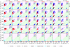 |
Fig. 8 ΔLy and ΔLz calculated over an integration time of 100 Gyr for the orbits of the HS’ stars in a potential with a triaxial NFW halo for a range of 1.00 < p < 1.04 and 1.13 < q < 1.23. The hiL stars are plotted in red, the loL stars in blue, and the subclump stars in black. The percentages indicate how many percent of the hiL stars are on y-tube orbits or resonantly trapped orbits (red percentage), how many loL stars are on z-tube orbits (blue percentage), and how many subclump stars are strongly resonantly trapped (black percentage). The coloured backgrounds indicate regions occupied by different orbit families (see Eq. (9)): resonantly trapped orbits, strongly resonantly trapped orbits, and resonant orbits, in light blue, blue, and darker blue, y-tube orbits in pink, and z-tube orbits in green. |
3.2 A simulated Helmi streams-like progenitor in a mildly triaxial potential
We investigated whether a simulated HS-like progenitor on a HSlike orbit would develop the structure seen (the hiL, loL clump) over a reasonable timescale in Galactic potentials for a range of p and q. To obtain realistic simulated HS-like phase-space positions that resemble the observations, we used Progenitor 4 of the set of four simulated HS-like dwarf galaxies by Koppelman et al. (2019b). This progenitor has two components: stars and dark matter. The star particles follow a Hernquist profile with a stellar mass of 108 M⊙ and a scale radius of 0.585 kpc. The DM halo particles follow a truncated NFW profile with a total mass of 3.62 ⋅ 109 M⊙.
To allow a good comparison to observations, we randomly selected 319 star particles (the same number as stars observed in the HS) that belong to the core of Progenitor 4, which we define as being the 73% most bound star particles. We placed the particles on a HS-like orbit by re-centring them to the position and velocity of a central HS star, which has (E, Lz, L⊥) = (−116 246 km2 s−2, 1272 kpc km s−1, 1871 kpc km s−1) and thus lies in the middle of the HS’s IoM distribution. The particles have an initial (Lz, L⊥) distribution that is positively correlated, meaning that particles with a larger Lz generally have a larger L⊥, and there is of course no gap present. We treated the particles as test particles and integrated their orbits in potentials with a range of 1.13 < q < 1.23 and 1.00 < p < 1.04, motivated by the results reported in the previous sections, over a timescale of 0–8 Gyr, where the upper limit is motivated by literature estimates for the accretion time of the HS (Kepley et al. 2007; Koppelman et al. 2019b; Naidu et al. 2022; Ruiz-Lara et al. 2022a), though these estimates need to be taken with caution given our findings (see Sect. 5.3 for a more in-depth discussion).
We inspected the behaviour of the particles in (Lz, L⊥) space over time. Of course, the particles’ orbits depend on exactly how the progenitor was re-centred, but the behaviour remains qualitatively similar for re-centrings to different central HS stars. Figure 9 shows the distribution in (Lz, L⊥) for q = 1.18, p = 1.02 for different snapshots and illustrates how the two clumps develop and a gap is formed over time. We see how particles on y-tube orbits separate themselves from the particles on z-tube orbits as their ΔLz is large. Particles that are resonantly trapped (in green), which have ΔLy, z < 1200 kpc km s−1, are located at (Lz, L⊥) values that are roughly consistent with those of the subclump. The final (Lz, L⊥) distribution at 8 Gyr resembles the observed HS distribution, showing two separated clumps of stars whose relative orientation is also roughly reproduced. This separation remains if we convolve the distribution with the expected observational errors.
In Fig. 10, we show different distributions after 8 Gyr of integration time for a few combinations of p and q (and Fig. E.1 shows the distributions after 8 Gyr for the entire range 1.13 < q < 1.23 and 1.00 < p < 1.04). For p = 1, the particles remain as a single clump, since in an axisymmetric potential they are all on z-tube orbits which have constant Lz. Instead, for p > 1, we find (Lz, L⊥) distributions that resemble the HS’ observations, with the cases of 1.18 < q < 1.21 and p ~ 1.02 matching the most convincingly, showing two separate clumps of stars. For p > 1.02, two clumps can also be created, but the extent in (Lz, L⊥) is larger than the range covered by the HS’ observations, and this extent grows as p gets larger. This is because Lz changes faster in a more triaxial potential. This means that there is a degeneracy between the accretion time and the value of p, as for a more recent (earlier) accretion time, a higher (lower) value of p gives similar (Lz, L⊥) distributions.
The characteristics of the progenitor determine its extent in IoM space. If we re-do our test-particle experiment using the smaller and lighter Progenitor 1 by Koppelman et al. (2019b, whose star particles follow a Hernquist profile with a stellar mass of 5 ⋅ 106 M⊙ and a scale radius of 0.164 kpc, and its DM halo particles follow a truncated NFW profile with a total mass of 1.9 ⋅ 108 M⊙), we similarly find that particles can be on different orbit families, but the extent in IoM space of the HS is not reproduced being too small. This confirms that Progenitor 4 provides a better description of the HS.
In summary, this experiment shows that a HS-like progenitor can evolve from a single clump in (Lz, L⊥) space to two clumps over time because of the local orbital structure of the Galactic potential. The two clumps form because their particles are, respectively, on y-tube orbits (with varying Lz) and z-tube orbits (with approximately constant Lz). The separatrix between these two orbit families is the Ωϕ:Ωz = 1:1 resonance, which can resonantly trap particles. A number of the resulting simulated distributions in (Lz, L⊥) space resemble the observed HS distribution well. Consequently, as we have shown that the HS require a specific local orbital structure, this allows us to place constraints on the inner DM halo’s shape of the MW using the observed HS’ dynamics. Following our findings in Section 3.1, we would favour Galactic potential models with (p, q) = (1.01, [1.17, 1.21]) and (p, q) = (1.02, [1.18, 1.20]), as then the observed HS stars are on the desired orbits. However, in this exploration all other Galactic potential parameters were kept fixed. Hence, to arrive at a more robust constraint, we allowed a larger number of free parameters to vary in the next Section.
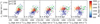 |
Fig. 9 Snapshots of the (Lz, L⊥) distribution at 0, 2, 4, 6, and 8 Gyr of integration for 319 particles with Helmi-Stream-like phase-space positions, selected from the re-centred Progenitor 4 by Koppelman et al. (2019b), in a potential with a triaxial NFW halo with p = 1.02 and q = 1.18. The colourbar indicates the variation in Lz, calculated over an integration time of 100 Gyr. At t = 0 Gyr, the (Lz, L⊥) distribution of the particles is positively correlated. The particles with ΔLz ≳ 2000 are on y-tube orbits, meaning their Lz is no longer conserved, making them move towards lower Lz in time with respect to the particles on z-tube orbits, which have ΔLz ≲ 1000. Particles with high initial L⊥ are strongly trapped by the Ωϕ : Ωz = 1:1 resonance (selected as ΔLy, z ≲ 750), and are encircled in green. A video, showing the behaviour of the particles in (Lz, L⊥) space over time, is available online. |
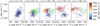 |
Fig. 10 (Lz, L⊥) distribution after 8 Gyr of integration time of 319 particles with Helmi-Stream-like phase-space positions, selected from the recentred Progenitor 4 by Koppelman et al. (2019b), in a potential with a triaxial NFW halo for a few combinations of p and q. Figure E.1 shows this plot for an extended grid of p and q values. The colourbar indicates the variation in Lz over an integration time of 100 Gyr. In the axisymmetric potential, p = 1.00, Lz is an IoM and all particles are on z-tube orbits. For p > 1, the particles with larger L⊥ are on y-tube orbits, meaning their Lz is no longer conserved, making them move towards lower Lz in time with respect to the particles on z-tube orbits. The timescale over which this happens depends on the degree of triaxiality of the potential, and in particular the value of p. A number of particles are strongly trapped by the Ωϕ : Ωz = 1:1 resonance (selected as ΔLy, z ≲ 750), and are encircled in green. A video, showing the behaviour of the particles in (Lz, L⊥) space for a range of p and q over time, is available online. |
4 A constraint on the Milky Way’s Galactic potential
4.1 Requiring a specific local orbital structure
We can strongly constrain the effective Galactic potential, and thus the potential’s characteristic parameters, in the region of phase-space probed by the HS, as the observable properties of the streams require a specific local orbital structure. That is what we set out to do in this section.
In Sect. 3.1.5, we found that in our Galactic potential models with (p, q) = (1.01, [1.17, 1.21]) and (p, q) = (1.02, [1.18, 1.20]) the HS stars are on orbits such that the formation of the HS clumps may be explained. However, this range of (p, q) values was obtained for a potential whose parameters were all fixed except for the shape of the DM halo. To provide a more robust estimate including uncertainties and to explore the influence of degeneracies, we proceeded to vary the disc mass, halo scale radius, halo density, p, and q while fitting the rotation curve data by Eilers et al. (2019) and Zhou et al. (2023), following the method outlined in Appendix A. We simultaneously maximised the number of subclump stars that are strongly resonantly trapped by the Ωϕ : Ωz = 1:1 resonance, which we translated into the requirement ΔLy,sub < 750 kpc km s−1 and ΔLz,sub < 750 kpc km s−1. We focused on this resonance as it is pivotal in setting the local orbital structure, and it is required to explain the existence of the kinematically cold subclump. We ran a Monte Carlo Markov Chain (MCMC) using emcee (Foreman-Mackey et al. 2013) with 40 walkers and 4000 steps. By performing the MCMC, we can estimate how much the location of the resonance shifts by varying parameters of the potential. Moreover, the MCMC can sample the parameter space more finely than we have done so far. Our likelihood has the form
![Mathematical equation: $\[\mathcal{L}(\boldsymbol{\theta})=-101+100 \cdot \frac{N_{\text {sub, strongly trapped }}}{N_{\text {sub, tot }}}-\frac{1}{2 N_{\mathrm{RC}}} \sum_{i=1}^{N_{\mathrm{RC}}}\left(\frac{v_{\mathrm{c}, i}^{\mathrm{d}}-v_{\mathrm{c}}^{\mathrm{m}}}{\sigma_{v_{\mathrm{c}, i}}}\right)^{2},\]$](/articles/aa/full_html/2024/11/aa51743-24/aa51743-24-eq18.png) (10)
(10)
where the superscript d indicates the data and m the model. The two likelihood terms have a relative importance of about 10:1, respectively. We set a simple flat prior and allowed
![Mathematical equation: $\[P(\boldsymbol{\theta})=\left\{\begin{array}{l}1\quad \text { if }\left\{\begin{array}{l}1.0 \leq p \leq 1.1 \\ 0.7 \leq q \leq 1.4 \\ 10 \leq r_{\mathrm{h}} \leq 30 \mathrm{~kpc} \\ 10^{5} \leq \rho_{0, \mathrm{~h}} \leq 10^{8} ~M_{\odot} \mathrm{~kpc}^{-3} \\ 3.5 \cdot 10^{10} \leq ~M_{\text {discs }} \leq 5.5 \cdot 10^{10} ~M_{\odot}\end{array}\right.\\ 0 \quad\text{otherwise},\end{array}\right.\]$](/articles/aa/full_html/2024/11/aa51743-24/aa51743-24-eq19.png) (11)
(11)
and took θi = [pi, qi, rh,i/kpc, ρ0,h,i/(M⊙ kpc−3), Mdiscs,i/M⊙] = [1.02, 1.20, 15.7, 10 ⋅ 106, 4.5 ⋅ 1010] as an initial guess, motivated by our findings and the parameters of the fiducial potential. Recall that we have fixed the discs scale-lengths and relative density near the Sun (see Appendix A), which is why we considered the sum of the masses of the thin and thick discs, Mdiscs, as the free parameter.
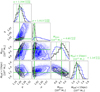 |
Fig. 11 Posterior distribution of the parameters q, p, Mdiscs, and MDM(<15 kpc) that maximises the number of subclump stars on strongly resonantly trapped orbits and fits the rotation curve data by Eilers et al. (2019) and Zhou et al. (2023), in blue. MCMC steps of walkers that got stuck have been removed. The posterior parameter distribution shown in black corresponds to potentials in which at least 40% of the loL stars are on z-tube orbits. The peak value of this distribution, which we take as our best estimate, is indicated in green solid lines in all panels, and was determined using a kernel-density estimation. The 31.73% (68.27%) percentile of the data lower (higher) than the peak value is taken as the lower (upper) 1σ uncertainty and are indicated with dotted green lines in the panels showing histograms of the marginalised distributions. The grey lines in those same panels show the kernel-density estimation of the marginalised distributions. |
4.2 Results
The MCMC converged, though with a relatively low acceptance fraction of ~0.27. We removed the first 1000 steps as burn-in and steps of walkers that got stuck. Figure 11 shows the posterior parameter distribution for p, q, Mdiscs, and MDM(<15kpc) in blue, where MDM(<15kpc) is computed by integrating Eq. (5) for a given rh, ρ0,h, p, and q within an ellipsoid which has a minor axis of 15 kpc and axis ratios set by p and q. We constrained ourselves to 15 kpc as this is the limit of our rotation curve data, and thus show MDM(<15kpc). In this context, the degeneracy between Mdiscs and MDM(<15kpc) seen in Fig. 11 is not surprising. The other degeneracies between the parameters can easily be explained as well. The degeneracy between the disc mass and q reflects the fact that the required local orbital structure constrains the total effective potential flattening. For a larger disc mass, a larger q is required to compensate for the flattening introduced by the disc. Following a similar reasoning, a more massive DM halo implies a lower q, though this degeneracy is weaker. The degeneracy between p and q reflects the fact that the Ωϕ:Ωz = 1:1 resonance is located on a diagonal line in p and q, see Figs. 4 and 8. In almost all unique potentials of the chain, ~99.6%, all nine subclump stars are strongly resonantly trapped. In more than 22% of the potentials, five or more subclump stars are on the resonant orbit while the rest is strongly resonantly trapped.
Though this posterior parameter distribution beautifully reflects where the subclump is resonantly trapped, it does not contain information about the orbits of the hiL and the loL stars. We find that in all potentials, the hiL stars are either resonantly trapped or on the y-tube orbits, as desired, but in a majority of the potentials, especially for larger p, most loL stars are on y-tube orbits as well. Therefore, we analyse the orbits of the loL stars in each sampled potential, and add the constraint that at least 40% of the loL stars are on z-tube orbits. This constrained posterior parameter distribution is shown in black in Fig. 11 and shows that a low p is required, in concordance with Fig. 8 (though in that case only p and q were varied).
We now proceed to determine our best-fit model. An inspection of Fig. 11 shows that the posterior distribution of p is skewed and that parameters are correlated. Hence, the median or average values of the marginalised distributions do not reflect the peak of the posterior parameter distribution. Therefore, to obtain the Galactic potential model that satisfies the likelihood best, we selected the global peak value of the posterior distribution. Next, we used scipy.stats.gaussian_kde to obtain a kerneldensity estimate of the posterior distribution, where we used the default settings but with a bandwidth (which scales the width of the kernel) equal to 2/3 ‘scott’ to capture the finer details of the distribution8. The peak values are those corresponding to the highest density and are shown with solid green lines in Fig. 11. Given the peak values, we then take the 31.73% (68.27%) percentile of the data lower (higher) than the peak value as the lower (upper) 1σ uncertainty. These are indicated with dashed green lines in Fig. 11. Hence, we find ![Mathematical equation: $\[p=1.013_{-0.006}^{+0.006}, ~q=1.204_{-0.036}^{+0.032}, ~M_{\text {discs }}=4.65_{-0.57}^{+0.47} \cdot 10^{10} ~M_{\odot}\]$](/articles/aa/full_html/2024/11/aa51743-24/aa51743-24-eq20.png) , and
, and ![Mathematical equation: $\[M_{\mathrm{DM}}(<15 \mathrm{kpc})=1.14_{-0.10}^{+0.11} \cdot 10^{11} ~M_{\odot}\]$](/articles/aa/full_html/2024/11/aa51743-24/aa51743-24-eq21.png) . In the best-fit potential, five subclump stars are on the resonance, while four are strongly resonantly trapped. All hiL stars are either on the resonance (9%), resonantly trapped (57%) or on y-tube orbits (21%) and 80% of the loL stars are on z-tube orbits. This is in agreement with our findings of Fig. 8.
. In the best-fit potential, five subclump stars are on the resonance, while four are strongly resonantly trapped. All hiL stars are either on the resonance (9%), resonantly trapped (57%) or on y-tube orbits (21%) and 80% of the loL stars are on z-tube orbits. This is in agreement with our findings of Fig. 8.
5 Discussion
5.1 Comparison to the literature
In this work, we have constrained the MW’s DM halo shape and characteristic parameters, and the mass of its discs. This is the first constraint on the degree of triaxiality of the DM inner halo and it is based on the dynamics of phase mixed streams. Here, we compare the Galactic potential characteristics that we found to the literature.
We constrained the discs’ total mass ![Mathematical equation: $\[M_{\text {discs }}=4.65_{-0.57}^{+0.47} \cdot 10^{10} ~M_{\odot}\]$](/articles/aa/full_html/2024/11/aa51743-24/aa51743-24-eq22.png) . Given that we assumed a fixed local density ratio and fixed parameters for the scale length and scale height, this implies
. Given that we assumed a fixed local density ratio and fixed parameters for the scale length and scale height, this implies ![Mathematical equation: $\[M_{\text {thin }}=3.12_{-0.38}^{+0.31} \cdot 10^{10} ~M_{\odot}\]$](/articles/aa/full_html/2024/11/aa51743-24/aa51743-24-eq23.png) and
and ![Mathematical equation: $\[M_{\text {thick }}= 1.53_{-0.19}^{+0.15} \cdot 10^{10} ~M_{\odot}\]$](/articles/aa/full_html/2024/11/aa51743-24/aa51743-24-eq24.png) . This is consistent with Bland-Hawthorn & Gerhard (2016) and references therein. We also constrained the total DM halo mass within 15 kpc to be
. This is consistent with Bland-Hawthorn & Gerhard (2016) and references therein. We also constrained the total DM halo mass within 15 kpc to be ![Mathematical equation: $\[M_{\text {DM }}({<}15 \mathrm{kpc})=1.14_{-0.10}^{+0.11} \cdot 10^{11} ~M_{\odot}\]$](/articles/aa/full_html/2024/11/aa51743-24/aa51743-24-eq25.png) . This corresponds to a local DM density of
. This corresponds to a local DM density of ![Mathematical equation: $\[\rho_{0, h}\left(R_{\odot}, z_{\odot}\right)=8.3_{-0.8}^{+1.1} \cdot 10^{-3} ~M_{\odot} ~\mathrm{pc}^{-3}\]$](/articles/aa/full_html/2024/11/aa51743-24/aa51743-24-eq26.png) or
or ![Mathematical equation: $\[0.32_{-0.03}^{+0.04} ~\mathrm{GeV} ~\mathrm{cm}^{-3}\]$](/articles/aa/full_html/2024/11/aa51743-24/aa51743-24-eq27.png) , which is consistent with the local DM densities of the models of McMillan (2017) and Cautun et al. (2020), but also with the compilation of estimates presented in Read (2014) and Bland-Hawthorn & Gerhard (2016). The total mass within 15 kpc is
, which is consistent with the local DM densities of the models of McMillan (2017) and Cautun et al. (2020), but also with the compilation of estimates presented in Read (2014) and Bland-Hawthorn & Gerhard (2016). The total mass within 15 kpc is ![Mathematical equation: $\[M_{\text {tot }}({<}15 \mathrm{kpc})=1.80_{-0.07}^{+0.08} \cdot 10^{11} ~M_{\odot}\]$](/articles/aa/full_html/2024/11/aa51743-24/aa51743-24-eq28.png) .
.
The posterior parameter distribution for the DM halo scale radius rh reveals that a value below the lower bound of 10 kpc would be preferred. This could indicate that a different DM profile is more suitable, possibly a contracted NFW (Cautun et al. 2020). We note that Ou et al. (2024) have suggested in their fit to recent rotation curve data that a cored Einasto profile provides a better fit over a (generalised) NFW profile. Despite being cored, their Einasto profile is relatively steep with an r−2 = 9.17 kpc, which is very comparable to the value we obtain (as rh = r−2 for an NFW profile).
Similar to the fiducial potential presented earlier (and discussed in Appendix A), the circular velocity at the position of the Sun is ![Mathematical equation: $\[233.3_{-2.1}^{+2.8}\]$](/articles/aa/full_html/2024/11/aa51743-24/aa51743-24-eq29.png) km s−1. Also the model’s rotation curve, shown in Fig. 1, agrees with the rotation curve of the fiducial potential. Lastly, we confirm that our model agrees with the determination of the vertical force 1.1 kpc from the Galactic plane as a function of radius by Bovy & Rix (2013).
km s−1. Also the model’s rotation curve, shown in Fig. 1, agrees with the rotation curve of the fiducial potential. Lastly, we confirm that our model agrees with the determination of the vertical force 1.1 kpc from the Galactic plane as a function of radius by Bovy & Rix (2013).
The HS constrain the shape and mass distribution of the effective Galactic potential, which is obtained by adding the contributions of all Galactic components. Fig. 12 shows the isopotential contours of the effective potential of our best-fit model in different planes. To place our findings in context, we compare our results to the effective flattening of Galactic potential models from the literature. We evaluate the shape of these models by approximating the effective isopotential at different radii by a triaxial ellipsoid and determining the axis ratios. Fig. 13 shows qΦ and pΦ as a function of Galactocentric coordinate x, while Fig. 14 shows qΦ at a fixed value, x = 15 kpc. The comparison in the innermost regions, x < 5 kpc, is not very meaningful as the curves differ due to different assumptions on the discs, bulge, and halo profile (for example Cautun et al. (2020) assumes a contracted DM halo, and Vasiliev (2024) assumes a heavier bulge). The constraints obtained from fitting spatially coherent streams result most often in oblate qϕ-values that agree within uncertainty with each other. It is important to note that all these works make different assumptions on the Galactic potential model and often choose different free parameters to vary. For example, Koposov et al. (2010) fit a onecomponent flattened logarithmic potential, while Küpper et al. (2015) assume a flattened NFW halo and keep their bulge and disc fixed. Bovy et al. (2016) and Malhan & Ibata (2019) start (in part) from a similar Galactic three-component potential model, but while Bovy et al. (2016) allows the disc parameters to vary, Malhan & Ibata (2019) does not. Ibata et al. (2024) and Palau & Miralda-Escudé (2023) assume two double-exponential density models to represent the thin and thick disc, and they represent the DM halo by a double-power-law density model with power-law slopes that are allowed to vary. A comparison of the resulting effective potential is therefore important, as it shows the effect of all mass components at once, but it may not be enough to fully grasp where the inconsistencies lie, as parametric models are always limited in their ability to fit the data (and recall also that individual streams contain different information about the Galactic potential depending on their orbit, Bonaca & Hogg 2018). For example, most analytical mass models assume a spherical DM halo, and as a consequence the resulting effective potentials are oblate in the region occupied by the HS. Instead, the effective flattening of our model turns prolate for x ≳ 13 kpc. We note that our findings agree with the work by Dodd et al. (2022) and Posti & Helmi (2019), and that also Vasiliev (2024)’s models turn prolate at x ~ 18 kpc.
As the HS constrain the effective potential, we cannot distinguish with certainty whether the measured triaxiality is due to the DM halo’s shape or to the effect of a perturbation such as the LMC. We can however neglect the triaxiality induced by the Galactic bar9 and spiral arms, as these do not strongly affect the dynamics of the HS since they orbit high above the plane (see Fig. 3). To investigate the effect of the LMC in the region probed by the HS, we compare pΦ of our model to the ℒ3, ℳ11 and ℒ2, ℳ11 time-dependent Galactic potential models by Vasiliev (2024). In these two models, the LMC is on its second passage around the MW. Both models have a MW halo with a virial mass of Mvir,MW = 11 ⋅ 1011 M⊙, and have MLMC = 3 ⋅ 1011 M⊙ and MLMC = 2 ⋅ 1011 M⊙, respectively (Vasiliev 2024). The right panel of Fig. 13 shows that the present-day perturbation of the LMC exceeds the triaxiality required by the HS, with 1 < pΦ < 1.06. However, at earlier times, the perturbation is of the same order as the required triaxiality. Although beyond the scope of this work, it could be worthwhile to investigate the behaviour of the HS orbits in a potential including both the LMC and a prolate, or better even, a non-parametric DM halo. The Vasiliev (2024) models assume a spherical NFW DM halo as a starting point, and as a consequence, all HS stars are on z-tube orbits and in (Lz, L⊥) space the HS’ clumps do not remain separated in time.
A preference for oblate shapes with alignment between the minor axis of the halo and the disc rotation axis is generally found in cosmological simulations (Bailin et al. 2005; DeBuhr et al. 2012; Shao et al. 2016; Chua et al. 2019; Prada et al. 2019). However, halo shapes may twist or stretch (Bailin et al. 2005; Emami et al. 2021; Shao et al. 2021), for example due to the presence of massive satellites (Baptista et al. 2023). So while our findings for q may seem at odds, there is agreement with our obtained value of p, as simulations produce DM halos that are close to being axisymmetric or spherical in the inner regions (Abadi et al. 2010; Dai et al. 2018; Chua et al. 2019; Prada et al. 2019; Cataldi et al. 2023). It would be interesting to compare our constraint to the shapes of MW analogues simulated in the correct environment (that is, Local Group-like) with an accretion history resembling that of the MW and including a massive satellite such as the LMC, as all these factors seem to influence the present-day DM halo shape (Vera-Ciro et al. 2011; Shao et al. 2021; Cataldi et al. 2023).
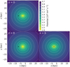 |
Fig. 12 Isopotential contours of the effective potential for the best-fit model of this work, on the plane y = 0 (top-left), z = 0 (bottom-left), and x = 0 (bottom right). For reference, the position of the Sun is indicated with a black plus sign. The effective potential transitions to roughly spherical at r ~ 15 kpc |
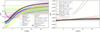 |
Fig. 13 Overview of the flattening of the effective potential qΦ and pΦ, as a function of Galactocentric distance along the x-axis for different analytical MW mass models, namely those by Bovy (2015), Price-Whelan (2017), McMillan (2017), and Cautun et al. (2020), and MW mass models constrained by stellar streams, namely Koposov et al. (2010) Küpper et al. (2015), Bovy et al. (2016), Malhan & Ibata (2019), Palau & Miralda-Escudé (2023), and Ibata et al. (2024), by globular cluster dynamics (Posti & Helmi 2019), and by previous work on the HS (Dodd et al. 2022). This figure also shows two Galactic potential models by Vasiliev (2024) with the ℒ3, ℳ11 and ℒ2, ℳ11 halo models at the present day in the left panel, and at different moments in time in the right panel. The black line shows the results obtained in this paper. The uncertainties derived for McMillan (2017), Posti & Helmi (2019), Cautun et al. (2020), Palau & Miralda-Escudé (2023), and this work have been obtained by randomly sampling 100 potentials from the respective chains, while for Küpper et al. (2015) and Malhan & Ibata (2019) we have sampled within the uncertainties quoted in those works. In all cases, we have taken the 16th and 84th percentile values. For Koposov et al. (2010) and Bovy et al. (2016) we show the uncertainties quoted in those works, and for Ibata et al. (2024) no uncertainties could be derived. Models that are based on constraints of the DM halo shape are shown with solid lines, models that assume a spherical DM halo are shown with dashed lines, and their similarity is apparent in qϕ at larger distance, except for the Vasiliev (2024) models, which take into account the infall of the LMC. The differences at small distances are due to varying assumptions on the discs and bulge, but are not relevant for the work presented here. |
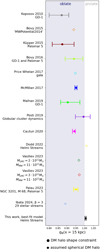 |
Fig. 14 Overview of the flattening of the effective potential qΦ at Galactocentric coordinate x = 15 kpc of different analytical MW mass models, namely those by Bovy (2015), Price-Whelan (2017), McMillan (2017), and Cautun et al. (2020), and MW mass models constrained by stellar streams, namely Koposov et al. (2010), Küpper et al. (2015), Bovy et al. (2016), Malhan & Ibata (2019), Palau & Miralda-Escudé (2023), and Ibata et al. (2024), globular cluster dynamics (Posti & Helmi 2019), and the HS (Dodd et al. 2022). This figure also shows two Galactic potential models by Vasiliev (2024) with the ℒ3, ℳ11 and ℒ2, ℳ11 halo models. Models that are based on constraints of the DM halo shape are shown with circles, models that assume a spherical DM halo are shown with diamonds. Solid symbols indicate models for which uncertainties on the effective potential could be derived, as described in the caption of Fig. 13. Open symbols indicate that no uncertainty on the potential parameters was available, and hence no uncertainty on the effective potential flattening could be derived. |
5.2 Limitations, uncertainties, and systematics
A number of simplifying assumptions have been made throughout this work. To start, we assumed that the DM halo follows an NFW profile with a triaxial shape whose axes are aligned with those defined by the MW disc. Recent work by Han et al. (2023a,b) has however suggested that the MW’s DM halo might be titled. Besides this, there is evidence that the MW’s DM halo could be contracted (see for example Dutton et al. 2016; Cautun et al. 2020) and follows a mass distribution whose shape may vary with radius (Vasiliev et al. 2021; Shao et al. 2021; Cataldi et al. 2023). Next, in all analyses performed in this work we have assumed a static potential. However, the effect of the LMC’s perturbation could prove important, as discussed in the previous section10. It would also be interesting to explore the local orbital structure for non-parametrised forms of the Galactic potential, using for example (low-order) basis function expansions (see for example Garavito-Camargo et al. 2021; Lilleengen et al. 2023; Vasiliev 2024).
The peculiar motion of the Sun also introduces a systematic uncertainty on the estimated values of p and q. A larger (smaller) value or the velocity of the Sun could lead to an overcorrection (undercorrection) when transforming from observables to Galactocentric coordinates. This means that we add (subtract) velocity to (from) the true motion of the stars, which in turn makes them reach farther (less far) out. In general, the farther away one is from the Galactic Centre, the more the effective potential becomes dominated by the DM halo (see also Fig. A.1). Hence, if all HS stars would have larger apocentres, the DM halo’s value of q that is needed to reach an effective flattening of qΦ = 1 would be smaller. We used the subclump stars to obtain an order of magnitude estimate of this effect. For these stars, a difference in vLSR and thus V⊙ of ~7 km s−1 leads to a shift in apocentre of ~2 kpc, while the pericentres remain similar. This in turns shifts the location of the Ωϕ : Ωz = 1:1 resonance in q by about ~0.03. Hence, the systematic uncertainty associated with this effect is σsys ~0.03, which is very small.
5.3 Accretion time estimate
In the literature, the asymmetry between the numbers of stars in the HS with positive and negative vz has been used to estimate the time of accretion time (Kepley et al. 2007; Koppelman et al. 2019b). However, such estimates will be biased towards more recent accretion times as the hiL clump, which we have established is on or close to a resonance, will phase mix more slowly. Therefore, to estimate the time of accretion, one should use the HS’ loL clump only. The loL clump’s ratio, ![Mathematical equation: $\[\frac{N_{\mathrm{loL}}\left(v_{z}^{+}\right)}{N_{\mathrm{loL}}\left(v_{z}^{-}\right)} \sim 0.62\]$](/articles/aa/full_html/2024/11/aa51743-24/aa51743-24-eq30.png) , is significantly different from the ratio we obtain for all HS stars,
, is significantly different from the ratio we obtain for all HS stars, ![Mathematical equation: $\[\frac{N_{\mathrm{HS}}\left(v_{z}^{+}\right)}{N_{\mathrm{HS}}\left(v_{z}^{-}\right)} \sim 0.24\]$](/articles/aa/full_html/2024/11/aa51743-24/aa51743-24-eq31.png) .
.
To illustrate how a resonance affects phase mixing timescales, we set up a test-particle simulation experiment. We used Progenitor 4 by Koppelman et al. (2019b) in a potential with p = 1.02 and q = 1.19 and explore two cases. Firstly, we integrated the orbit of a subclump star, which is on the Ωϕ:Ωz = 1:1 resonance, to an apocentre 8 Gyr ago and recentred Progenitor 4 to that 6D phase-space coordinate. We then integrated the orbits of all particles forward to the present day. We selected particles that are in a local volume, that is, d < 2.5 kpc, and inspected their positions and velocities. The result is shown in the top two rows of Fig. 15. A large part of the Progenitor 4 particles is resonantly trapped, as is evident from the flattened particle distribution in the (y, z) plane. We clearly see that Progenitor 4 is not yet fully phase mixed and its streams can still be identified as coherent structures in configuration space. Moreover, the local volume particles have a tight distribution in velocity space and a low ![Mathematical equation: $\[\frac{N\left(v_{z}^{+}\right)}{N\left(v_{z}^{-}\right)} \sim 0.01\]$](/articles/aa/full_html/2024/11/aa51743-24/aa51743-24-eq32.png) ratio. Next, we followed the same procedure but used a loL star, which is on a z-tube orbit, for re-centring. The result is shown in the bottom two rows of Fig. 15. The particles appear more mixed, as they show less substructure in configuration space, have a more diffuse velocity distribution, and a significantly higher
ratio. Next, we followed the same procedure but used a loL star, which is on a z-tube orbit, for re-centring. The result is shown in the bottom two rows of Fig. 15. The particles appear more mixed, as they show less substructure in configuration space, have a more diffuse velocity distribution, and a significantly higher ![Mathematical equation: $\[\frac{N\left(v_{z}^{+}\right)}{N\left(v_{z}^{-}\right)} \sim 0.7\]$](/articles/aa/full_html/2024/11/aa51743-24/aa51743-24-eq33.png) ratio. We find that the velocity distribution and the vz ratio of the particles match the loL observations roughly after at least 5 Gyr of evolution, implying that, according to this experiment, the HS were likely accreted at least 5 Gyr ago. This accretion time estimate is robust to recentrings to different loL-like orbits and to forward or backward integration, as is expected for a structure on a regular, non-resonant orbit. This experiment emphasises that the degree of asymmetry in the number of stars associated with streams that have undergone some amount of phase mixing cannot be straightforwardly used to estimate accretion times when a substructure is located close to or on a resonance (a similar conclusion seems to apply to the streams from GES, see Dillamore et al. 2024, although in this case, due to resonances with the Galactic bar).
ratio. We find that the velocity distribution and the vz ratio of the particles match the loL observations roughly after at least 5 Gyr of evolution, implying that, according to this experiment, the HS were likely accreted at least 5 Gyr ago. This accretion time estimate is robust to recentrings to different loL-like orbits and to forward or backward integration, as is expected for a structure on a regular, non-resonant orbit. This experiment emphasises that the degree of asymmetry in the number of stars associated with streams that have undergone some amount of phase mixing cannot be straightforwardly used to estimate accretion times when a substructure is located close to or on a resonance (a similar conclusion seems to apply to the streams from GES, see Dillamore et al. 2024, although in this case, due to resonances with the Galactic bar).
An independent measure of the accretion time of the HS can be derived from the rate of variation in Lz of the y-tube orbits. Fig. 10 shows that the timescale over which Lz varies is linked to the value of p: a larger value of p implies a faster change in Lz. Fig. 10 shows the (Lz, L⊥) distribution of the particles after 8 Gyr of integration time, and p > 1.02 results in distributions that span a too large range in Lz compared to the observations. However, the same figure but for an integration time of 4 or 6 Gyr shows two clumps in the (Lz, L⊥) distribution with an extent resembling the HS observations for p = 1.03 and p = 1.04, respectively. What exact value of p is preferred in these test-particle simulations thus depends on the accretion time of the HS. Since our MCMC results, based on the observed HS stars, indicate that p ≲ 1.02, this allows us to tentatively constrain the HS’ accretion time to about at least 6 Gyr ago, confirming our earlier estimate based on the degree of phase mixing seen for the loL streams.
6 Conclusion
We studied the dynamical properties of the (phase mixed) HS using Gaia DR3 data and used it to constrain the Galactic potential within 20 kpc, the region probed by the streams stars’ orbits. The dynamics of the HS are peculiar, as their stars separate into two clumps in angular momentum space (Dodd et al. 2022), of which one has a larger total angular momentum (hiL) than the other (loL). The phase-space distribution of the HS indicate that the hiL clump is less phase mixed than the loL clump, as is apparent from their vz distribution. We also confirmed that the hiL clump contains substructure in the form of a kinematically cold subclump (known as S2, see Myeong et al. 2018).
To explain these characteristics, we studied the orbital structure in the volume of phase-space probed by the HS in a range of Galactic potentials models with a triaxial NFW halo, parametrised by the (density) axis ratios p and q. We used the Lyapunov exponent as chaos indicator, the variation in Lz and Ly to classify orbits, and orbital frequencies (ΩR, Ωϕ, Ωz) to identify resonances. We find that for triaxial DM halos with flattening q ~ 1.2, the Ωϕ:Ωz = 1:1 resonance acts as a separatrix between z-tube and y-tube orbits, which are orbits that rotate around the z − and y-axis, respectively. In the case of p < 1, this resonance causes chaoticity, while for p > 1, this resonance stabilises orbits and resonantly traps them. This means p > 1 is favoured, as it is able to sustain the kinematically cold subclump. The location of the resonance in relation to the hiL and loL clumps, and therefore also the transition in orbit family, varies with (p, q). Consequently, there is a region of (p, q) parameter space where the hiL clump is on a different orbit family than the loL clump, providing an explanation of the longevity and separation of the clumps. Specifically, we find that the hiL clump can be partially resonantly trapped, while the kinematically cold subclump is strongly resonantly trapped and the loL clump is located offresonance, and this in turn explains their different degrees of phase mixing. In such Galactic potential models, the hiL and loL clump with the correct dynamical characteristics can be formed over time from a single progenitor, which we demonstrated by integrating and inspecting the orbits of simulated star particles of a HS-like progenitor.
We took these findings a step further and used them to constrain the characteristics of the Galactic potential. We performed a Monte Carlo Markov Chain sampling of Galactic potential models in which we varied p, q, the total disc (thin and thick) mass, and DM halo scale radius and density, and we required the kinematically cold subclump to be resonantly trapped on the Ωϕ:Ωz = 1:1 resonance. We also required the model to fit recent rotation curve data (Eilers et al. 2019; Zhou et al. 2023). Additionally, we required that at least 40% of the loL stars is on z-tube orbits. We find ![Mathematical equation: $\[p=1.013_{-0.006}^{+0.006}, ~q=1.204_{-0.036}^{+0.032}, ~M_{\text {discs }}= 4.65_{-0.57}^{+0.47} \cdot 10^{10} ~M_{\odot}\]$](/articles/aa/full_html/2024/11/aa51743-24/aa51743-24-eq34.png) , and
, and ![Mathematical equation: $\[M_{\mathrm{DM}}({<}15 \mathrm{kpc})=1.14_{-0.10}^{+0.11} \cdot 10^{11} ~M_{\odot}\]$](/articles/aa/full_html/2024/11/aa51743-24/aa51743-24-eq35.png) . Our best-fit model has
. Our best-fit model has ![Mathematical equation: $\[v_{\mathrm{c}}\left(R_{\odot}\right)=233.3_{-2.1}^{+2.8} \mathrm{~km} \mathrm{~s}^{-1}\]$](/articles/aa/full_html/2024/11/aa51743-24/aa51743-24-eq36.png) . In the best-fit potential, five subclump stars are on the resonance, while four are strongly resonantly trapped. All hiL stars are either on the resonance (9%), resonantly trapped (57%) or on y-tube orbits (21%), and 80% of the loL stars are on z-tube orbits. Our constraint on the shape of the DM halo is extremely strong. This can be explained by the fact that we combine precise rotation curve data, which strongly constrains the mass enclosed on the midplane of the Galaxy, with a constraint on the local orbital structure of the potential, which depends on the effective shape and characteristics of the potential.
. In the best-fit potential, five subclump stars are on the resonance, while four are strongly resonantly trapped. All hiL stars are either on the resonance (9%), resonantly trapped (57%) or on y-tube orbits (21%), and 80% of the loL stars are on z-tube orbits. Our constraint on the shape of the DM halo is extremely strong. This can be explained by the fact that we combine precise rotation curve data, which strongly constrains the mass enclosed on the midplane of the Galaxy, with a constraint on the local orbital structure of the potential, which depends on the effective shape and characteristics of the potential.
Our findings suggest that the orbital structure of the potential can strongly influence the dynamical properties of substructures in the Galaxy, especially if these are located near a separatrix. Among the possible consequences, it may complicate the identification of debris due to chaos which accelerates phase mixing (Price-Whelan et al. 2016; Yavetz et al. 2023). Furthermore the determination of the accretion time may also affected due to the presence of resonances which in contrast slows down the process of phase mixing. On the other hand, it gives us a powerful and exciting new tool to probe the orbital structure of the potential, and hence its characteristic parameters (Caranicolas & Zotos 2010; Zotos 2014), as is shown in this work.
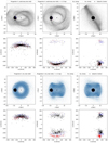 |
Fig. 15 Phase space distribution of Progenitor 4 by Koppelman et al. (2019b) on two different orbits after 8 Gyr of integration time in a potential with p = 1.02, q = 1.19. Particles within a local volume selection, that is, d < 2.5 kpc, are shown in black. For comparison, the hiL and loL HS stars are shown in red and blue, respectively. The top two rows show the particles of Progenitor 4 at the present day after it has been re-centred and integrated forward from the 6 D phase-space coordinate of a subclump star 8 Gyr ago, which is resonantly trapped on the Ωϕ:Ωz = 1:1 resonance. Consequently, a large part of the Progenitor 4 particles is resonantly trapped, as is evident from the substructure in configuration space, the flattened particle distribution in the (y, z) plane and the low |
![Mathematical equation: $\[\frac{N\left(v_{z}^{+}\right)}{N\left(v_{z}^{-}\right)} \sim 0.01\]$](/articles/aa/full_html/2024/11/aa51743-24/aa51743-24-eq37.png)
![Mathematical equation: $\[\frac{N\left(v_{z}^{+}\right)}{N\left(v_{z}^{-}\right)} \sim 0.7\]$](/articles/aa/full_html/2024/11/aa51743-24/aa51743-24-eq38.png)
Data availability
Appendix C and D of this article can be found at https://zenodo.org/records/13881903.
Movies associated with Figs. 9, 10, and E.1 are available at https://www.aanda.org.
Movies
Movie 1 associated with Fig. 9 Access Supplementary Material
Movie 2 associated with Fig. 10 and E.1 Access Supplementary Material
Acknowledgements
This research has been supported by a Spinoza Grant from the Dutch Research Council (NWO). We thank the anonymous referee for constructive comments on the paper. HCW thanks Carles Palau, Lorenzo Posti, and Paul McMillan for providing the chains of their MCMC runs. This work has made use of data from the European Space Agency (ESA) mission Gaia (https://www.cosmos.esa.int/gaia), processed by the Gaia Data Processing and Analysis Consortium (DPAC, https://www.cosmos.esa.int/web/gaia/dpac/consortium). Funding for the DPAC has been provided by national institutions, in particular the institutions participating in the Gaia Multilateral Agreement. Throughout this work, we’ve made use of the following packages: astropy (Astropy Collaboration 2013), emcee (Foreman-Mackey et al. 2013), corner (Foreman-Mackey 2016), vaex (Breddels & Veljanoski 2018), SciPy (Virtanen et al. 2020), matplotlib (Hunter 2007), NumPy (van der Walt et al. 2011), AGAMA (Vasiliev 2019), SuperFreq (Price-Whelan 2015), pyGadgetReader (Thompson 2014), and Jupyter Notebooks (Kluyver et al. 2016).
Appendix A Our fiducial Galactic potential model
Throughout this work, we used a modified version of the McMillan (2017) potential. The McMillan (2017) potential is an axisymmetric potential model consisting of a bulge, an exponential thin and thick disc, a HI gas disc, a molecular gas disc, and a spherical NFW DM halo. Since recent work has shown that this model might be slightly too heavy (for example Eilers et al. 2019; Jiao et al. 2023), we performed a simple Monte Carlo Markov Chain using emcee Foreman-Mackey et al. (2013) with 40 walkers and a 1000 steps to optimise the scale radius of the halo rh, the density of the halo ρ0,h, and Mdiscs, the sum of the thin and thick disc mass, assuming a thick disc scale length of Rthick = 2 kpc (Bland-Hawthorn & Gerhard 2016) and a fixed local density normalisation fd,⊙ = ρthick(R⊙, z⊙)/ρthin(R⊙, z⊙) = 0.12 (McMillan 2017; ?). Furthermore, following Dodd et al. (2022), we assumed an axisymmetric halo with a density flattening q = 1.2. We used rotation curve data with associated uncertainties derived using axisymmetric Jeans equations by Eilers et al. (2019)11, who used Gaia DR2 data, and Zhou et al. (2023)12, who used APOGEE, LAMOST, 2MASS, and Gaia EDR3 data and employed supervised machine-learning to obtain distances13. We restricted ourselves conservatively to rotation curve data with R < 15 kpc, because beyond this radius systematic errors associated with assumptions behind the methods used to derive the rotation curve become important (Koop et al. 2024). However, we checked that if we take data within R < 20 kpc, our conclusions remain similar. We set a simple flat prior and allowed
![Mathematical equation: $\[P(\boldsymbol{\theta})= \begin{cases}1 \quad\text { if }\left\{\begin{array}{l}10 \leq r_{\mathrm{h}} \leq 30 ~\mathrm{kpc} \\10^5 \leq \rho_{0, \mathrm{~h}} \leq 10^8 ~M_{\odot} ~\mathrm{kpc}^{-3} \\3 \cdot 10^{10} \leq M_{\mathrm{discs}} \leq 5.5 \cdot 10^{10} ~M_{\odot} \\\end{array} \quad\right.\\ 0 \quad\text{otherwise}.\end{cases}\]$](/articles/aa/full_html/2024/11/aa51743-24/aa51743-24-eq39.png) (A.1)
(A.1)
We find vc(R⊙) = 233.2 ± 2.6 km s−1 and median and percentiles ![Mathematical equation: $\[r_{\mathrm{h}}=15.7_{-4.4}^{+8.8} ~\mathrm{kpc}, ~\rho_{\mathrm{h}, 0}=10_{-5}^{+8} \cdot 10^{6} ~M_{\odot} ~\mathrm{kpc}^{-3}\]$](/articles/aa/full_html/2024/11/aa51743-24/aa51743-24-eq40.png) , and
, and ![Mathematical equation: $\[M_{\text {discs }}= 4.5_{-0.7}^{+0.6} \cdot 10^{10} ~M_{\odot}\]$](/articles/aa/full_html/2024/11/aa51743-24/aa51743-24-eq41.png) , and used these median values throughout this work to set our fiducial potential. The contributions as a function of radius of all components of the potential are shown in Fig. A.1. The total mass within 20 kpc, the region probed by the HS, of this model is
, and used these median values throughout this work to set our fiducial potential. The contributions as a function of radius of all components of the potential are shown in Fig. A.1. The total mass within 20 kpc, the region probed by the HS, of this model is ![Mathematical equation: $\[M_{\text {tot }}(r<20 \mathrm{kpc})=2.2_{-0.1}^{+0.1} \cdot 10^{11} ~M_{\odot}\]$](/articles/aa/full_html/2024/11/aa51743-24/aa51743-24-eq42.png) , compatible with other estimates (for example Küpper et al. 2015; Posti & Helmi 2019; Watkins et al. 2019; Eadie & Jurić 2019).
, compatible with other estimates (for example Küpper et al. 2015; Posti & Helmi 2019; Watkins et al. 2019; Eadie & Jurić 2019).
Appendix B Orbital frequencies determination
To recover the fundamental orbital frequencies corresponding to a star’s orbit, we used a modified version of SuperFreq (Price-Whelan 2015). SuperFreq is an implementation of the Numerical Analysis of Fundamental Frequencies (NAFF) method (Laskar 1993; Valluri & Merritt 1998). It performs a Fast Fourier Transform of a complex time series w(t) + ivw(t), where w are the coordinates, for example Poincaré symplectic coordinates (Papaphilippou & Laskar 1996) or Cartesian coordinates. If a 3D time series is inputted, SuperFreq stores the three frequency spectra (frequency and amplitude) of each of the time series and sorts them by amplitude. Next, the frequency with the highest amplitude is chosen as the first leading frequency. It then determines the second leading frequency by picking the frequency with the second highest amplitude, requiring it to be of a different coordinate and requiring a minimum difference in frequency between the first two leading frequencies (this difference is by default set to 10−6 but can be changed). In a similar way, the third leading frequency is found. This set of three leading frequencies typically corresponds to the set of three fundamental frequencies, but this does not necessarily need to be the case, something that was noted by Dodd et al. (2022) and Beraldo e Silva et al. (2023) as well.
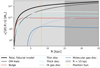 |
Fig. A.1
|
![Mathematical equation: $\[\frac{v_{\mathrm{c}}^{2}(R) R}{G}\]$](/articles/aa/full_html/2024/11/aa51743-24/aa51743-24-eq43.png)
To make the fundamental frequency determination more robust, we proceeded as follows. We integrated orbits for 100 Gyr, as the longer an orbit is integrated, the more reliable the frequency determination becomes (Valluri et al. 2010; Wang et al. 2016). We outputted orbits each 10 Myr and constructed a set of three time series in Poincaré symplectic polar coordinates for each orbit14. This was used as input for SuperFreq, which determines the frequency spectra with settings Nintvec = 15 and break condition = None.15. We started with the z coordinate, and from its frequency spectrum define the frequency with the highest amplitude to be Ωz. Next, we filtered the frequency spectra of R and ϕ such that frequencies that are a multiple of Ωz are removed. This was done by requiring a minimum difference of 10−4 between Ωϕ and Ωz and ΩR. Of course, this presents issues if the orbit in question is a resonant orbit. Therefore, we step wise made the required minimum difference smaller (10−5, 10−6, 10−7, 10−8) if the peak that is picked results in an unexpected frequency ratio. For the HS, this translates to the requirement abs(Ωϕ:Ωz − 1) < 0.15, which effectively means that we assumed that all Helmi Stream stars have orbital frequencies that are drawn from a continuous distribution, that is, they have values that are within a certain range. Next, the frequency with the highest amplitude in the ϕ spectrum was chosen as Ωϕ. Then, the remaining frequency spectrum of R was filtered such that the R frequencies that are a multiples of Ωϕ were removed. Finally, the frequency with highest amplitude that is independent was chosen as ΩR. However, as linear integer combinations of this peak with Ωz or Ωϕ may appear, one needs to be careful to choose the peak that corresponds to the independent ΩR. For the HS, this was done by requiring that abs(ΩR : Ωz − 0.7) < 0.15. The fact that multiples of the peaks in Ωz, Ωϕ and ΩR appear in all three spectra is indicative of the fact that the motion in R, ϕ and z is coupled. The procedure to determine the orbital frequencies is illustrated in Fig. B.1 and solves the problem of the ficticious Ωz : ΩR = 1 : 2 branch reported by Dodd et al. (2022).
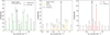 |
Fig. B.1 Frequency spectra and determined fundamental (fund.) orbital frequencies of the orbit of a randomly chosen HS’ star in the fiducial potential (see Appendix A) for an integration time of 100 Gyr, outputted each 10 Myr. The filtered (filt.) spectra for ΩR(Ωϕ) correspond to spectra out of which the multiples of Ωz and Ωϕ(Ωz) are filtered. For ΩR, we see that the leading frequency of the spectrum is twice Ωz. However, the orbit’s phase-space distribution does not suggest it is a resonant orbit, and this value for ΩR does not fall within the range abs(ΩR : Ωz − 0.7) < 0.15), and it is valid to choose the next-highest peak as fundamental ΩR. |
Appendix E Progenitor 4 in potentials with different (p, q)
In Sect. 3.2 we explored the (Lz, L⊥) distributions of Progenitor 4 particles after they have have been re-centred to the 6D phase-space coordinates of a central HS star 8 Gyr ago and integrated forward to the present day. Figure E.1 shows the (Lz, L⊥) distribution after 8 Gyr of integration time for the range 1.13 < q < 1.23 and 1.00 < p < 1.04. For the range 1.18< q < 1.21 and 1.02 < p < 1.03 we find distributions that match the HS’ observations most convincingly, showing two separated clumps of stars, driven by the fact that the stars in the two clumps are on different orbital families.
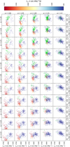 |
Fig. E.1 Snapshot of the (Lz, L⊥) distribution after 8 Gyr of integration time of 319 particles with Helmi-Stream-like phase-space positions, selected from the re-centred Progenitor 4 by Koppelman et al. (2019b), in Galactic potentials with a triaxial NFW halo for a range of p and q. The colourbar indicates the variation in Lz over an integration time of 100 Gyr. In the axisymmetric potential, p = 1.00, Lz is an IoM and all particles are on z-axis tube orbits. For p > 1, the particles with larger L⊥ are on y-axis tube orbits, meaning their Lz is no longer conserved, making them move towards lower Lz in time with respect to the particles on z-axis tube orbits. The timescale over which this happens depends on the degree of triaxiality of the potential, and in particular the value of p. A number of particles are strongly trapped by the Ωϕ : Ωz 1:1 resonance (selected as ΔLy, z ≲ 750), and are encircled in green. A video, showing the behaviour of the particles in (Lz, L⊥) space over time, is available online. |
References
- Abadi, M. G., Navarro, J. F., Fardal, M., Babul, A., & Steinmetz, M. 2010, MNRAS, 407, 435 [NASA ADS] [CrossRef] [Google Scholar]
- Aguado, D. S., Myeong, G. C., Belokurov, V., et al. 2021, MNRAS, 500, 889 [NASA ADS] [Google Scholar]
- Anguiano, B., Majewski, S. R., Allende Prieto, C., et al. 2018, A&A, 620, A76 [NASA ADS] [CrossRef] [EDP Sciences] [Google Scholar]
- Astropy Collaboration (Robitaille, T. P., et al.) 2013, A&A, 558, A33 [NASA ADS] [CrossRef] [EDP Sciences] [Google Scholar]
- Bailin, J., Kawata, D., Gibson, B. K., et al. 2005, ApJ, 627, L17 [Google Scholar]
- Baptista, J., Sanderson, R., Huber, D., et al. 2023, ApJ, 958, 44 [NASA ADS] [CrossRef] [Google Scholar]
- Belokurov, V., Erkal, D., Evans, N. W., Koposov, S. E., & Deason, A. J. 2018, MNRAS, 478, 611 [Google Scholar]
- Bensby, T., Alves-Brito, A., Oey, M. S., Yong, D., & Meléndez, J. 2011, ApJ, 735, L46 [NASA ADS] [CrossRef] [Google Scholar]
- Beraldo e Silva, L., Debattista, V. P., Anderson, S. R., et al. 2023, ApJ, 955, 38 [NASA ADS] [CrossRef] [Google Scholar]
- Binney, J., & Tremaine, S. 2008, Galactic Dynamics, 2nd edn. (Princeton University Press) [Google Scholar]
- Bland-Hawthorn, J., & Gerhard, O. 2016, ARA&A, 54, 529 [Google Scholar]
- Bonaca, A., & Hogg, D. W. 2018, ApJ, 867, 101 [NASA ADS] [CrossRef] [Google Scholar]
- Bonaca, A., Naidu, R. P., Conroy, C., et al. 2021, ApJ, 909, L26 [NASA ADS] [CrossRef] [Google Scholar]
- Bovy, J. 2015, ApJS, 216, 29 [NASA ADS] [CrossRef] [Google Scholar]
- Bovy, J., & Rix, H.-W. 2013, ApJ, 779, 115 [Google Scholar]
- Bovy, J., Bahmanyar, A., Fritz, T. K., & Kallivayalil, N. 2016, ApJ, 833, 31 [NASA ADS] [CrossRef] [Google Scholar]
- Breddels, M. A., & Veljanoski, J. 2018, A&A, 618, A13 [NASA ADS] [CrossRef] [EDP Sciences] [Google Scholar]
- Callingham, T. M., Cautun, M., Deason, A. J., et al. 2022, MNRAS, 513, 4107 [NASA ADS] [CrossRef] [Google Scholar]
- Caranicolas, N., & Zotos, E. 2010, Astron. Nachr., 331, 330 [NASA ADS] [CrossRef] [Google Scholar]
- Carlberg, R. G. 2018, ApJ, 861, 69 [NASA ADS] [CrossRef] [Google Scholar]
- Cataldi, P., Pedrosa, S. E., Tissera, P. B., & Artale, M. C. 2021, MNRAS, 501, 5679 [NASA ADS] [CrossRef] [Google Scholar]
- Cataldi, P., Pedrosa, S. E., Tissera, P. B., et al. 2023, MNRAS, 523, 1919 [NASA ADS] [CrossRef] [Google Scholar]
- Cautun, M., Benítez-Llambay, A., Deason, A. J., et al. 2020, MNRAS, 494, 4291 [Google Scholar]
- Chiba, M., & Beers, T. C. 2000, AJ, 119, 2843 [NASA ADS] [CrossRef] [Google Scholar]
- Chua, K. T. E., Pillepich, A., Vogelsberger, M., & Hernquist, L. 2019, MNRAS, 484, 476 [Google Scholar]
- Cooper, A. P., Cole, S., Frenk, C. S., et al. 2010, MNRAS, 406, 744 [Google Scholar]
- Dai, B., Robertson, B. E., & Madau, P. 2018, ApJ, 858, 73 [NASA ADS] [CrossRef] [Google Scholar]
- DeBuhr, J., Ma, C.-P., & White, S. D. M. 2012, MNRAS, 426, 983 [NASA ADS] [CrossRef] [Google Scholar]
- Dillamore, A. M., Belokurov, V., & Evans, N. W. 2024, MNRAS, 532, 4389 [NASA ADS] [CrossRef] [Google Scholar]
- Do, T., Hees, A., Ghez, A., et al. 2019, Science, 365, 664 [Google Scholar]
- Dodd, E., Helmi, A., & Koppelman, H. H. 2022, A&A, 659, A61 [NASA ADS] [CrossRef] [EDP Sciences] [Google Scholar]
- Dodd, E., Callingham, T. M., Helmi, A., et al. 2023, A&A, 670, L2 [NASA ADS] [CrossRef] [EDP Sciences] [Google Scholar]
- Dutton, A. A., Macciò, A. V., Dekel, A., et al. 2016, MNRAS, 461, 2658 [NASA ADS] [CrossRef] [Google Scholar]
- Eadie, G., & Jurić, M. 2019, ApJ, 875, 159 [NASA ADS] [CrossRef] [Google Scholar]
- Eilers, A.-C., Hogg, D. W., Rix, H.-W., & Ness, M. K. 2019, ApJ, 871, 120 [Google Scholar]
- Emami, R., Genel, S., Hernquist, L., et al. 2021, ApJ, 913, 36 [NASA ADS] [CrossRef] [Google Scholar]
- Fattahi, A., Deason, A. J., Frenk, C. S., et al. 2020, MNRAS, 497, 4459 [NASA ADS] [CrossRef] [Google Scholar]
- Forbes, D. A. 2020, MNRAS, 493, 847 [Google Scholar]
- Foreman-Mackey, D. 2016, J. Open Source Softw., 1, 24 [Google Scholar]
- Foreman-Mackey, D., Hogg, D. W., Lang, D., & Goodman, J. 2013, PASP, 125, 306 [Google Scholar]
- Frenk, C. S., White, S. D. M., Davis, M., & Efstathiou, G. 1988, ApJ, 327, 507 [NASA ADS] [CrossRef] [Google Scholar]
- Gaia Collaboration (Vallenari, A., et al.) 2023, A&A, 674, A1 [NASA ADS] [CrossRef] [EDP Sciences] [Google Scholar]
- Garavito-Camargo, N., Besla, G., Laporte, C. F. P., et al. 2019, ApJ, 884, 51 [NASA ADS] [CrossRef] [Google Scholar]
- Garavito-Camargo, N., Besla, G., Laporte, C. F. P., et al. 2021, ApJ, 919, 109 [NASA ADS] [CrossRef] [Google Scholar]
- GRAVITY Collaboration (Abuter, R., et al.) 2018, A&A, 615, L15 [NASA ADS] [CrossRef] [EDP Sciences] [Google Scholar]
- GRAVITY Collaboration (Abuter, R., et al.) 2021, A&A, 647, A59 [NASA ADS] [CrossRef] [EDP Sciences] [Google Scholar]
- Han, J. J., Conroy, C., & Hernquist, L. 2023a, Nat. Astron., 7, 1481 [CrossRef] [Google Scholar]
- Han, J. J., Semenov, V., Conroy, C., & Hernquist, L. 2023b, ApJ, 957, L24 [CrossRef] [Google Scholar]
- Helmi, A. 2020, ARA&A, 58, 205 [Google Scholar]
- Helmi, A., White, S. D. M., de Zeeuw, P. T., & Zhao, H. 1999, Nature, 402, 53 [Google Scholar]
- Helmi, A., Babusiaux, C., Koppelman, H. H., et al. 2018, Nature, 563, 85 [Google Scholar]
- Horta, D., Schiavon, R. P., Mackereth, J. T., et al. 2020, MNRAS, 493, 3363 [NASA ADS] [CrossRef] [Google Scholar]
- Horta, D., Schiavon, R. P., Mackereth, J. T., et al. 2021, MNRAS, 500, 1385 [Google Scholar]
- Horta, D., Schiavon, R. P., Mackereth, J. T., et al. 2023, MNRAS, 520, 5671 [NASA ADS] [CrossRef] [Google Scholar]
- Hunter, J. D. 2007, Comput. Sci. Eng., 9, 90 [NASA ADS] [CrossRef] [Google Scholar]
- Ibata, R. A., Gilmore, G., & Irwin, M. J. 1994, Nature, 370, 194 [Google Scholar]
- Ibata, R., Malhan, K., Tenachi, W., et al. 2024, ApJ, 967, 89 [NASA ADS] [CrossRef] [Google Scholar]
- Ivezić, Ž., Goldston, J., Finlator, K., et al. 2000, AJ, 120, 963 [CrossRef] [Google Scholar]
- Jiao, Y., Hammer, F., Wang, H., et al. 2023, A&A, 678, A208 [NASA ADS] [CrossRef] [EDP Sciences] [Google Scholar]
- Jurić, M., Ivezić, Ž., Brooks, A., et al. 2008, ApJ, 673, 864 [Google Scholar]
- Kepley, A. A., Morrison, H. L., Helmi, A., et al. 2007, AJ, 134, 1579 [NASA ADS] [CrossRef] [Google Scholar]
- Kluyver, T., Ragan-Kelley, B., Pérez, F., et al. 2016, in Positioning and Power in Academic Publishing: Players, Agents and Agendas, eds. F. Loizides, & B. Scmidt (IOS Press), 87 [Google Scholar]
- Koop, O., Antoja, T., Helmi, A., Callingham, T. M., & Laporte, C. F. P. 2024, A&A, submitted [arXiv:2405.19028] [Google Scholar]
- Koposov, S. E., Rix, H.-W., & Hogg, D. W. 2010, ApJ, 712, 260 [Google Scholar]
- Koppelman, H. H., Helmi, A., Massari, D., Price-Whelan, A. M., & Starkenburg, T. K. 2019a, A&A, 631, L9 [NASA ADS] [CrossRef] [EDP Sciences] [Google Scholar]
- Koppelman, H. H., Helmi, A., Massari, D., Roelenga, S., & Bastian, U. 2019b, A&A, 625, A5 [NASA ADS] [CrossRef] [EDP Sciences] [Google Scholar]
- Kruijssen, J. M. D., Pfeffer, J. L., Reina-Campos, M., Crain, R. A., & Bastian, N. 2019, MNRAS, 486, 3180 [Google Scholar]
- Kruijssen, J. M. D., Pfeffer, J. L., Chevance, M., et al. 2020, MNRAS, 498, 2472 [NASA ADS] [CrossRef] [Google Scholar]
- Küpper, A. H. W., Balbinot, E., Bonaca, A., et al. 2015, ApJ, 803, 80 [Google Scholar]
- Laskar, J. 1993, Celest. Mech. Dyn. Astron., 56, 191 [NASA ADS] [CrossRef] [Google Scholar]
- Law, D. R., & Majewski, S. R. 2010, ApJ, 714, 229 [Google Scholar]
- Leung, H. W., Bovy, J., Mackereth, J. T., et al. 2023, MNRAS, 519, 948 [Google Scholar]
- Li, Y.-S., & Helmi, A. 2009, in The Galaxy Disk in Cosmological Context, 254, eds. J. Andersen, Nordströara, B. m, & J. Bland-Hawthorn, 263 [Google Scholar]
- Li, H., Tan, K., & Zhao, G. 2018, ApJS, 238, 16 [CrossRef] [Google Scholar]
- Lilleengen, S., Petersen, M. S., Erkal, D., et al. 2023, MNRAS, 518, 774 [Google Scholar]
- Lindegren, L., Bastian, U., Biermann, M., et al. 2021, A&A, 649, A4 [EDP Sciences] [Google Scholar]
- Lövdal, S. S., Ruiz-Lara, T., Koppelman, H. H., et al. 2022, A&A, 665, A57 [NASA ADS] [CrossRef] [EDP Sciences] [Google Scholar]
- Malhan, K., & Ibata, R. A. 2019, MNRAS, 486, 2995 [NASA ADS] [CrossRef] [Google Scholar]
- Malhan, K., Ibata, R. A., Sharma, S., et al. 2022, ApJ, 926, 107 [NASA ADS] [CrossRef] [Google Scholar]
- Massari, D., Koppelman, H. H., & Helmi, A. 2019, A&A, 630, L4 [NASA ADS] [CrossRef] [EDP Sciences] [Google Scholar]
- Mateu, C. 2023, MNRAS, 520, 5225 [Google Scholar]
- Matsuno, T., Dodd, E., Koppelman, H. H., et al. 2022, A&A, 665, A46 [NASA ADS] [CrossRef] [EDP Sciences] [Google Scholar]
- McMillan, P. J. 2017, MNRAS, 465, 76 [NASA ADS] [CrossRef] [Google Scholar]
- Mestre, M., Llinares, C., & Carpintero, D. D. 2020, MNRAS, 492, 4398 [NASA ADS] [CrossRef] [Google Scholar]
- Mróz, P., Udalski, A., Skowron, D. M., et al. 2019, ApJ, 870, L10 [Google Scholar]
- Myeong, G. C., Evans, N. W., Belokurov, V., Amorisco, N. C., & Koposov, S. E. 2018, MNRAS, 475, 1537 [NASA ADS] [CrossRef] [Google Scholar]
- Myeong, G. C., Vasiliev, E., Iorio, G., Evans, N. W., & Belokurov, V. 2019, MNRAS, 488, 1235 [Google Scholar]
- Naidu, R. P., Conroy, C., Bonaca, A., et al. 2020, ApJ, 901, 48 [Google Scholar]
- Naidu, R. P., Conroy, C., Bonaca, A., et al. 2022, ApJ, submitted [arXiv:2204.09057] [Google Scholar]
- Nissen, P. E., Silva-Cabrera, J. S., & Schuster, W. J. 2021, A&A, 651, A57 [NASA ADS] [CrossRef] [EDP Sciences] [Google Scholar]
- Niu, Z., Yuan, H., & Liu, J. 2023, ApJ, 950, 104 [NASA ADS] [CrossRef] [Google Scholar]
- Ou, X., Eilers, A.-C., Necib, L., & Frebel, A. 2024, MNRAS, 528, 693 [NASA ADS] [CrossRef] [Google Scholar]
- Palau, C. G., & Miralda-Escudé, J. 2023, MNRAS, 524, 2124 [NASA ADS] [CrossRef] [Google Scholar]
- Papaphilippou, Y., & Laskar, J. 1996, A&A, 307, 427 [NASA ADS] [Google Scholar]
- Papaphilippou, Y., & Laskar, J. 1998, A&A, 329, 451 [NASA ADS] [Google Scholar]
- Pascale, R., Nipoti, C., & Ciotti, L. 2022, MNRAS, 509, 1465 [Google Scholar]
- Posti, L., & Helmi, A. 2019, A&A, 621, A56 [NASA ADS] [CrossRef] [EDP Sciences] [Google Scholar]
- Prada, J., Forero-Romero, J. E., Grand, R. J. J., Pakmor, R., & Springel, V. 2019, MNRAS, 490, 4877 [NASA ADS] [CrossRef] [Google Scholar]
- Price-Whelan, A. M. 2015, https://doi.org/10.5281/zenodo. 18787 [Google Scholar]
- Price-Whelan, A. M. 2017, J. Open Source Softw., 2 [Google Scholar]
- Price-Whelan, A. M., Johnston, K. V., Valluri, M., et al. 2016, MNRAS, 455, 1079 [NASA ADS] [CrossRef] [Google Scholar]
- Read, J. I. 2014, J. Phys. G Nucl. Phys., 41, 063101 [Google Scholar]
- Reid, M. J., & Brunthaler, A. 2004, ApJ, 616, 872 [Google Scholar]
- Ruiz-Lara, T., Helmi, A., Gallart, C., Surot, F., & Cassisi, S. 2022a, A&A, 668, L10 [NASA ADS] [CrossRef] [EDP Sciences] [Google Scholar]
- Ruiz-Lara, T., Matsuno, T., Lövdal, S. S., et al. 2022b, A&A, 665, A58 [NASA ADS] [CrossRef] [EDP Sciences] [Google Scholar]
- Schönrich, R., Binney, J., & Dehnen, W. 2010, MNRAS, 403, 1829 [NASA ADS] [CrossRef] [Google Scholar]
- Shao, S., Cautun, M., Frenk, C. S., et al. 2016, MNRAS, 460, 3772 [NASA ADS] [CrossRef] [Google Scholar]
- Shao, S., Cautun, M., Deason, A., & Frenk, C. S. 2021, MNRAS, 504, 6033 [CrossRef] [Google Scholar]
- Smith, M. C., Evans, N. W., Belokurov, V., et al. 2009, MNRAS, 399, 1223 [Google Scholar]
- Sormani, M. C., Gerhard, O., Portail, M., Vasiliev, E., & Clarke, J. 2022, MNRAS, 514, L1 [NASA ADS] [CrossRef] [Google Scholar]
- Springel, V., White, S. D. M., & Hernquist, L. 2004, in Dark Matter in Galaxies, 220, eds. S. Ryder, D. Pisano, M. Walker, & K. Freeman, 421 [Google Scholar]
- Thompson, R. 2014, pyGadgetReader: GADGET snapshot reader for python, Astrophysics Source Code Library [record ascl:1411.001] [Google Scholar]
- Tian, H.-J., Liu, C., Carlin, J. L., et al. 2015, ApJ, 809, 145 [NASA ADS] [CrossRef] [Google Scholar]
- Valluri, M., & Merritt, D. 1998, ApJ, 506, 686 [NASA ADS] [CrossRef] [Google Scholar]
- Valluri, M., Debattista, V. P., Quinn, T., & Moore, B. 2010, MNRAS, 403, 525 [CrossRef] [Google Scholar]
- Valluri, M., Debattista, V. P., Quinn, T. R., Roškar, R., & Wadsley, J. 2012, MNRAS, 419, 1951 [NASA ADS] [CrossRef] [Google Scholar]
- van der Walt, S., Colbert, S. C., & Varoquaux, G. 2011, Comput. Sci. Eng., 13, 22 [Google Scholar]
- Vargya, D., Sanderson, R., Sameie, O., et al. 2022, MNRAS, 516, 2389 [NASA ADS] [CrossRef] [Google Scholar]
- Vasiliev, E. 2019, MNRAS, 482, 1525 [Google Scholar]
- Vasiliev, E. 2024, MNRAS, 527, 437 [Google Scholar]
- Vasiliev, E., & Belokurov, V. 2020, MNRAS, 497, 4162 [Google Scholar]
- Vasiliev, E., Belokurov, V., & Erkal, D. 2021, MNRAS, 501, 2279 [NASA ADS] [CrossRef] [Google Scholar]
- Vera-Ciro, C., & Helmi, A. 2013, ApJ, 773, L4 [Google Scholar]
- Vera-Ciro, C. A., Sales, L. V., Helmi, A., et al. 2011, MNRAS, 416, 1377 [NASA ADS] [CrossRef] [Google Scholar]
- Villalobos, Á., Kazantzidis, S., & Helmi, A. 2010, ApJ, 718, 314 [NASA ADS] [CrossRef] [Google Scholar]
- Virtanen, P., Gommers, R., Oliphant, T. E., et al. 2020, Nat. Methods, 17, 261 [Google Scholar]
- Vogelsberger, M., White, S. D. M., Helmi, A., & Springel, V. 2008, MNRAS, 385, 236 [NASA ADS] [CrossRef] [Google Scholar]
- Wang, Y., Athanassoula, E., & Mao, S. 2016, MNRAS, 463, 3499 [NASA ADS] [CrossRef] [Google Scholar]
- Wang, H.-F., Chrobáková, Ž., López-Corredoira, M., & Sylos Labini, F. 2023, ApJ, 942, 12 [NASA ADS] [CrossRef] [Google Scholar]
- Watkins, L. L., van der Marel, R. P., Sohn, S. T., & Evans, N. W. 2019, ApJ, 873, 118 [NASA ADS] [CrossRef] [Google Scholar]
- White, S. D. M., & Rees, M. J. 1978, MNRAS, 183, 341 [Google Scholar]
- Xiang, M., & Rix, H.-W. 2022, Nature, 603, 599 [NASA ADS] [CrossRef] [Google Scholar]
- Yanny, B., Newberg, H. J., Kent, S., et al. 2000, ApJ, 540, 825 [NASA ADS] [CrossRef] [Google Scholar]
- Yavetz, T. D., Johnston, K. V., Pearson, S., Price-Whelan, A. M., & Weinberg, M. D. 2021, MNRAS, 501, 1791 [Google Scholar]
- Yavetz, T. D., Johnston, K. V., Pearson, S., Price-Whelan, A. M., & Hamilton, C. 2023, ApJ, 954, 215 [NASA ADS] [CrossRef] [Google Scholar]
- Zavala, J., & Frenk, C. S. 2019, Galaxies, 7, 81 [NASA ADS] [CrossRef] [Google Scholar]
- Zbinden, O., & Saha, P. 2019, RNAAS, 3, 73 [NASA ADS] [Google Scholar]
- Zhang, R., Matsuno, T., Li, H., et al. 2024, ApJ, 966, 174 [NASA ADS] [CrossRef] [Google Scholar]
- Zhao, G., Zhao, Y.-H., Chu, Y.-Q., Jing, Y.-P., & Deng, L.-C. 2012, Res. Astron. Astrophys., 12, 723 [NASA ADS] [CrossRef] [Google Scholar]
- Zhou, Y., Li, X., Huang, Y., & Zhang, H. 2023, ApJ, 946, 73 [CrossRef] [Google Scholar]
- Zotos, E. E. 2014, A&A, 563, A19 [NASA ADS] [CrossRef] [EDP Sciences] [Google Scholar]
- Zotos, E. E., & Carpintero, D. D. 2013, Celest. Mech. Dyn. Astron., 116, 417 [NASA ADS] [CrossRef] [Google Scholar]
We used a right-handed Galactocentric Cartesian coordinate system and denote the coordinates as (x, y, z, vx, vy, vz). The GC is at its centre, x increases in the disc plane away from the location of the Sun, meaning the Sun is located at negative x, y points in the direction of Galactic rotation and z points towards the North Galactic Pole. Galactocentric cylindrical coordinates are denoted as (R, ϕ, z, vR, vϕ, vz).
A value of Rthick = 2 kpc is in agreement with the findings of Bensby et al. (2011) and Bland-Hawthorn & Gerhard (2016) and references therein. Such a thick disc thus has a smaller scale length than the thin disc, Rthin = 2.5 kpc, as we could expect from their formation histories (see for example Villalobos et al. 2010; Xiang & Rix 2022).
Stochastic regions are found in near- or non-integrable potentials, and generally realistic galactic potential models are of this type.
The reason that there are more hiL stars than loL stars, a ratio of ~2 : 3, could be caused by the fact that the loL clump is located closer to the disc in integrals of motion space, which results in a stronger background, possibly making it harder for the clustering algorithm to pick up the structure.
This set of three orbital frequencies is not necessarily equal to the three fundamental orbital frequencies discussed in Sect. 2.2.
To this end, we updated the initial density ρ0,i of a DM halo with a given p and q to ρ0,new, while we kept the other components of the potential fixed. We used that vc(R⊙)2 = vc,baryons(R⊙)2 + vc,halo(R⊙)2, where vc,baryons(R⊙) is the contribution of all baryonic components to vc(R⊙), which is fixed, and vc,halo(R⊙) is the contribution of the DM halo. Since vc,halo(R⊙) follows the proportionality vc,halo(R⊙)2 ∝ ρ0, we compute the density ![Mathematical equation: $\[\rho_{0, \text {new}}=\frac{233.2^{2}-v_{\mathrm{c} \text {,baryons }}\left(R_{\odot}\right)^{2}}{v_{\mathrm{c}, \text {halo}}^{2}\left(R_{\odot}\right)} \rho_{0, \mathrm{i}}\]$](/articles/aa/full_html/2024/11/aa51743-24/aa51743-24-eq44.png) .
.
For example, in a simple axisymmetric case, z is the short axis if q < 1, while z is the long axis if q > 1.
The obtained peak values are consistent when the default bandwidth ‘scott’ or ‘silverman’ is used, which are determined using Scott’s Rule and Silverman’s Rule, respectively. For a bandwidth equal to 1/2 ‘scott’, a local maximum instead of the global maximum is obtained.
We have studied the orbits of the HS in Galactic potentials with a triaxial NFW halo for a range of p and q replacing the bulge by the bar model presented in Sormani et al. (2022) (while ensuring that vc(R⊙) = 233.2 km s−1). Although in the case of q = 1 a minor part of the HS stars can be affected by the l/m = 1 bar resonance (depending on the pattern speed), this does not explain the nature of the two clumps. For q = 1.2, no stars are on orbits resonant with the bar.
The MW is also being perturbed by the ongoing merger with the Sagittarius dwarf galaxy (Ibata et al. 1994). However, we expect that it is unlikely that this led to the formation of the two clumps, as all stars will have felt the perturbation equally independent of their orbital phase. Furthermore, Sgr’s effect on the HS’ dynamics was investigated in the context of Dodd et al. (2022)’s work and concluded to be negligible (Dodd, priv. comm.). Interestingly, though, the HS and Sagittarius have similar orbital frequency ratios, possibly suggesting a connection, such as group infall (Li & Helmi 2009).
In the case of Eilers et al. (2019), we took the mean of the measured uncertainties and added the systematic uncertainties (extracted from their Fig. 4), assuming a systematic uncertainty of 12% for the five bins largest in R, quadratrically, such that ![Mathematical equation: $\[\sigma_{\mathrm{v}_{\mathrm{c}}, \text {tot}}^{2}=\sigma_{\text {meas}}^{2}+\sigma_{\text {syst }}^{2}\]$](/articles/aa/full_html/2024/11/aa51743-24/aa51743-24-eq45.png) . We treated the different contributions to the total systematic uncertainties as independent and add them quadratically.
. We treated the different contributions to the total systematic uncertainties as independent and add them quadratically.
In the case of Zhou et al. (2023), we similarly added the systematic uncertainties (extracted from their Fig. 12) quadratically and also treated the different contributions to the total systematic uncertainty as independent by summing them quadratically.
We used these two datasets as they use consistent values for R⊙, v⊙, and z⊙. Alternative works on rotation curves make different assumptions on their solar motion and position. For example, Wang et al. (2023) assumes R⊙ = 8.34 kpc and z⊙ = 0.027 kpc, and Ou et al. (2024) assumes R⊙ = 8.178 kpc and z⊙ = 0.0208 kpc. This in turn leads to different adopted values of the solar motion.
Poincaré’s symplectic polar coordinates, a variation on cylindrical polar coordinates, are used as input for SuperFreq throughout this work, and thus also in the case of mildly triaxial potentials. This choice of coordinates ensures relatively good results and gives more information about the orbital properties than for example the orbital frequencies in Cartesian coordinates do.
To a certain extent, the frequencies recovered by the algorithm are dependent on the settings in the code, as also shown by Wang et al. (2016).
All Figures
|
Fig. 1 Rotation curves of a variety of MW mass models. We have plotted here the models by Bovy (2015), Price-Whelan (2017), McMillan (2017), and Cautun et al. (2020), and two models by Vasiliev (2024) using his ℒ3, ℳ11 and ℒ2, ℳ11 halo models at the present day. The grey line shows the rotation curve of the fiducial model (described in Sect. 2.1 and Appendix A). The black line shows the best-fit potential of this work (described in Sect. 4.2), while the grey shaded area correspond to the 16th to 84th percentile range for 200 potentials from the MCMC chains. The rotation curve data used in the fit includes Eilers et al. (2019)’s rotation curve data, shown in magenta, and Zhou et al. (2023)’s in yellow. The light grey shaded area marks the region R > 15 kpc and data in this distance range was not included in the MCMC fit. However, the fit is similar even if data up to R ~ 20 kpc is used. |
| In the text | |
|
Fig. 2 Distribution of the HS in IoM-space defined as E, Lz, and L⊥ (left), velocity (middle), and configuration space (right) separated in the hiL clump (red, 191 stars in total) and loL clump (blue, 128 stars in total) based on the stars’ position in (Lz, L⊥) space, see top-left panel. The subclump, a kinematically cold, coherent group of stars, is indicated in black. The stars in the background of the energy and angular momentum distributions correspond to the selection of local halo stars (d < 2.5 kpc) by Dodd et al. (2023). The energy values have been computed in the fiducial potential (see Appendix A). Histograms on the top and right of each plot show the one-dimensional distributions. The error bars on the data points denote the uncertainties. The hiL clump has on average lower Lz, higher L⊥, higher energy, larger |vz| and lower vy. |
| In the text | |
|
Fig. 3 Pericentre, apocentre, and zmax distribution of the HS’ orbits in the fiducial potential (see Appendix A). The hiL stars are indicated in red, the loL stars in blue and the subclump with black edges as in Fig. 2. Histograms on the top and right of the top plot show the one-dimensional distributions. The apocentres and pericentres were determined as the maximum and minimum distance from the Galactic Centre that the orbit reached over an integration time of 10 Gyr. An estimate for the uncertainties was obtained by randomly sampling the observables a 1000 times within their uncertainties after integrating their orbits. |
| In the text | |
|
Fig. 4 Various dynamical quantities of the loL stars (left column) and hiL stars (middle column) and subclump stars (right column) in a potential with a triaxial halo with a range of p and q as calculated by AGAMA for an integration time of 100 Gyr. The grey horizontal line at p = 1 serves to guide the eye and indicates axisymmetric potentials. The white dotted line indicates the Ωϕ : Ωz = 1:1 resonance (see also bottom row). Top row: average Lyapunov exponent. A non-zero Lyapunov exponent indicates that there is chaoticity. The overlaid black contours, which are also shown in the other rows, map average(Λ*) at the levels of 0.02 and 0.04, as is also indicated on the colourbar. Second row: median variation in Lz, with ΔLz,* = max(Lz,*) − min(Lz,*) over the entire integration time. Third row: median variation in Ly, with ΔLy,* = max(Ly,*) − min(Ly,*) over the entire integration time. Bottom row: median(Ωϕ : Ωz) ratio. We can see clear correspondences between the four different rows. The chaotic regions overlap with the median(Ωϕ : Ωz) = 1:1 resonance and a transition in the value of ΔLz and ΔLy. This transition indicates a change in orbit family, and the text in the middle column indicates where the different orbit families reside, of which examples are shown in Fig. 5 (the crosses in this figure indicate their p and q). To the left of the chaotic band we find z-tube orbits, which have an oscillating Ly and a roughly conserved Lz, such that median(ΔLy) ≲ 4000 kpc km s−1, median(ΔLz) ≲ 500 kpc km s−1. To the right of the chaotic band we find y-tube orbits, which have a roughly conserved Ly and an oscillating Lz, such that median(ΔLy) ~ 1000 kpc km s−1 and median(Δ Lz) ~ 3000 kpc km s−1. For p > 1, the Ωϕ:Ωz = 1:1 is a resonance that traps orbits, which reduces their variation in both Ly and Lz. This is most clear for the subclump stars. |
| In the text | |
|
Fig. 5 Orbits integrated for 25 Gyr for a randomly selected hiL star in different triaxial potentials. Top row: p = 0.97, q = 1.08, resulting in a z-tube orbit(green). Second row: a y-tube orbit for p = 1.05, q = 1.11 (pink). Third row: a resonant orbit for p = 1.05, q = 1.245 (cyan). Bottom row: a chaotic orbit with Λ = 0.12 for p = 0.83, q = 0.977888. |
| In the text | |
|
Fig. 6 Behaviour over time of Lz, Ly, and L⊥ for the orbits shown in Fig. 5. Since the z-tube orbits around the z-axis, it has a roughly conserved Lz and L⊥, but a time-varying Ly. Similarly, since the y-tube orbits around the y-axis, it has a roughly conserved Ly and L⊥ but a time-varying Lz. For the chaotic orbit, Lz, Ly, and L⊥ vary largely in time. The resonant orbit has a small variation in Ly, Lz, and L⊥. |
| In the text | |
|
Fig. 7 Resonance trapping in a potential with a triaxial NFW halo with p = 1.02 and q = 1.19. The left panel depicts with different colours the variation in angular momentum, |
| In the text | |
|
Fig. 8 ΔLy and ΔLz calculated over an integration time of 100 Gyr for the orbits of the HS’ stars in a potential with a triaxial NFW halo for a range of 1.00 < p < 1.04 and 1.13 < q < 1.23. The hiL stars are plotted in red, the loL stars in blue, and the subclump stars in black. The percentages indicate how many percent of the hiL stars are on y-tube orbits or resonantly trapped orbits (red percentage), how many loL stars are on z-tube orbits (blue percentage), and how many subclump stars are strongly resonantly trapped (black percentage). The coloured backgrounds indicate regions occupied by different orbit families (see Eq. (9)): resonantly trapped orbits, strongly resonantly trapped orbits, and resonant orbits, in light blue, blue, and darker blue, y-tube orbits in pink, and z-tube orbits in green. |
| In the text | |
|
Fig. 9 Snapshots of the (Lz, L⊥) distribution at 0, 2, 4, 6, and 8 Gyr of integration for 319 particles with Helmi-Stream-like phase-space positions, selected from the re-centred Progenitor 4 by Koppelman et al. (2019b), in a potential with a triaxial NFW halo with p = 1.02 and q = 1.18. The colourbar indicates the variation in Lz, calculated over an integration time of 100 Gyr. At t = 0 Gyr, the (Lz, L⊥) distribution of the particles is positively correlated. The particles with ΔLz ≳ 2000 are on y-tube orbits, meaning their Lz is no longer conserved, making them move towards lower Lz in time with respect to the particles on z-tube orbits, which have ΔLz ≲ 1000. Particles with high initial L⊥ are strongly trapped by the Ωϕ : Ωz = 1:1 resonance (selected as ΔLy, z ≲ 750), and are encircled in green. A video, showing the behaviour of the particles in (Lz, L⊥) space over time, is available online. |
| In the text | |
|
Fig. 10 (Lz, L⊥) distribution after 8 Gyr of integration time of 319 particles with Helmi-Stream-like phase-space positions, selected from the recentred Progenitor 4 by Koppelman et al. (2019b), in a potential with a triaxial NFW halo for a few combinations of p and q. Figure E.1 shows this plot for an extended grid of p and q values. The colourbar indicates the variation in Lz over an integration time of 100 Gyr. In the axisymmetric potential, p = 1.00, Lz is an IoM and all particles are on z-tube orbits. For p > 1, the particles with larger L⊥ are on y-tube orbits, meaning their Lz is no longer conserved, making them move towards lower Lz in time with respect to the particles on z-tube orbits. The timescale over which this happens depends on the degree of triaxiality of the potential, and in particular the value of p. A number of particles are strongly trapped by the Ωϕ : Ωz = 1:1 resonance (selected as ΔLy, z ≲ 750), and are encircled in green. A video, showing the behaviour of the particles in (Lz, L⊥) space for a range of p and q over time, is available online. |
| In the text | |
|
Fig. 11 Posterior distribution of the parameters q, p, Mdiscs, and MDM(<15 kpc) that maximises the number of subclump stars on strongly resonantly trapped orbits and fits the rotation curve data by Eilers et al. (2019) and Zhou et al. (2023), in blue. MCMC steps of walkers that got stuck have been removed. The posterior parameter distribution shown in black corresponds to potentials in which at least 40% of the loL stars are on z-tube orbits. The peak value of this distribution, which we take as our best estimate, is indicated in green solid lines in all panels, and was determined using a kernel-density estimation. The 31.73% (68.27%) percentile of the data lower (higher) than the peak value is taken as the lower (upper) 1σ uncertainty and are indicated with dotted green lines in the panels showing histograms of the marginalised distributions. The grey lines in those same panels show the kernel-density estimation of the marginalised distributions. |
| In the text | |
|
Fig. 12 Isopotential contours of the effective potential for the best-fit model of this work, on the plane y = 0 (top-left), z = 0 (bottom-left), and x = 0 (bottom right). For reference, the position of the Sun is indicated with a black plus sign. The effective potential transitions to roughly spherical at r ~ 15 kpc |
| In the text | |
|
Fig. 13 Overview of the flattening of the effective potential qΦ and pΦ, as a function of Galactocentric distance along the x-axis for different analytical MW mass models, namely those by Bovy (2015), Price-Whelan (2017), McMillan (2017), and Cautun et al. (2020), and MW mass models constrained by stellar streams, namely Koposov et al. (2010) Küpper et al. (2015), Bovy et al. (2016), Malhan & Ibata (2019), Palau & Miralda-Escudé (2023), and Ibata et al. (2024), by globular cluster dynamics (Posti & Helmi 2019), and by previous work on the HS (Dodd et al. 2022). This figure also shows two Galactic potential models by Vasiliev (2024) with the ℒ3, ℳ11 and ℒ2, ℳ11 halo models at the present day in the left panel, and at different moments in time in the right panel. The black line shows the results obtained in this paper. The uncertainties derived for McMillan (2017), Posti & Helmi (2019), Cautun et al. (2020), Palau & Miralda-Escudé (2023), and this work have been obtained by randomly sampling 100 potentials from the respective chains, while for Küpper et al. (2015) and Malhan & Ibata (2019) we have sampled within the uncertainties quoted in those works. In all cases, we have taken the 16th and 84th percentile values. For Koposov et al. (2010) and Bovy et al. (2016) we show the uncertainties quoted in those works, and for Ibata et al. (2024) no uncertainties could be derived. Models that are based on constraints of the DM halo shape are shown with solid lines, models that assume a spherical DM halo are shown with dashed lines, and their similarity is apparent in qϕ at larger distance, except for the Vasiliev (2024) models, which take into account the infall of the LMC. The differences at small distances are due to varying assumptions on the discs and bulge, but are not relevant for the work presented here. |
| In the text | |
|
Fig. 14 Overview of the flattening of the effective potential qΦ at Galactocentric coordinate x = 15 kpc of different analytical MW mass models, namely those by Bovy (2015), Price-Whelan (2017), McMillan (2017), and Cautun et al. (2020), and MW mass models constrained by stellar streams, namely Koposov et al. (2010), Küpper et al. (2015), Bovy et al. (2016), Malhan & Ibata (2019), Palau & Miralda-Escudé (2023), and Ibata et al. (2024), globular cluster dynamics (Posti & Helmi 2019), and the HS (Dodd et al. 2022). This figure also shows two Galactic potential models by Vasiliev (2024) with the ℒ3, ℳ11 and ℒ2, ℳ11 halo models. Models that are based on constraints of the DM halo shape are shown with circles, models that assume a spherical DM halo are shown with diamonds. Solid symbols indicate models for which uncertainties on the effective potential could be derived, as described in the caption of Fig. 13. Open symbols indicate that no uncertainty on the potential parameters was available, and hence no uncertainty on the effective potential flattening could be derived. |
| In the text | |
|
Fig. 15 Phase space distribution of Progenitor 4 by Koppelman et al. (2019b) on two different orbits after 8 Gyr of integration time in a potential with p = 1.02, q = 1.19. Particles within a local volume selection, that is, d < 2.5 kpc, are shown in black. For comparison, the hiL and loL HS stars are shown in red and blue, respectively. The top two rows show the particles of Progenitor 4 at the present day after it has been re-centred and integrated forward from the 6 D phase-space coordinate of a subclump star 8 Gyr ago, which is resonantly trapped on the Ωϕ:Ωz = 1:1 resonance. Consequently, a large part of the Progenitor 4 particles is resonantly trapped, as is evident from the substructure in configuration space, the flattened particle distribution in the (y, z) plane and the low |
| In the text | |
|
Fig. A.1
|
| In the text | |
|
Fig. B.1 Frequency spectra and determined fundamental (fund.) orbital frequencies of the orbit of a randomly chosen HS’ star in the fiducial potential (see Appendix A) for an integration time of 100 Gyr, outputted each 10 Myr. The filtered (filt.) spectra for ΩR(Ωϕ) correspond to spectra out of which the multiples of Ωz and Ωϕ(Ωz) are filtered. For ΩR, we see that the leading frequency of the spectrum is twice Ωz. However, the orbit’s phase-space distribution does not suggest it is a resonant orbit, and this value for ΩR does not fall within the range abs(ΩR : Ωz − 0.7) < 0.15), and it is valid to choose the next-highest peak as fundamental ΩR. |
| In the text | |
|
Fig. E.1 Snapshot of the (Lz, L⊥) distribution after 8 Gyr of integration time of 319 particles with Helmi-Stream-like phase-space positions, selected from the re-centred Progenitor 4 by Koppelman et al. (2019b), in Galactic potentials with a triaxial NFW halo for a range of p and q. The colourbar indicates the variation in Lz over an integration time of 100 Gyr. In the axisymmetric potential, p = 1.00, Lz is an IoM and all particles are on z-axis tube orbits. For p > 1, the particles with larger L⊥ are on y-axis tube orbits, meaning their Lz is no longer conserved, making them move towards lower Lz in time with respect to the particles on z-axis tube orbits. The timescale over which this happens depends on the degree of triaxiality of the potential, and in particular the value of p. A number of particles are strongly trapped by the Ωϕ : Ωz 1:1 resonance (selected as ΔLy, z ≲ 750), and are encircled in green. A video, showing the behaviour of the particles in (Lz, L⊥) space over time, is available online. |
| In the text | |
Current usage metrics show cumulative count of Article Views (full-text article views including HTML views, PDF and ePub downloads, according to the available data) and Abstracts Views on Vision4Press platform.
Data correspond to usage on the plateform after 2015. The current usage metrics is available 48-96 hours after online publication and is updated daily on week days.
Initial download of the metrics may take a while.