| Issue |
A&A
Volume 691, November 2024
|
|
|---|---|---|
| Article Number | A109 | |
| Number of page(s) | 27 | |
| Section | Interstellar and circumstellar matter | |
| DOI | https://doi.org/10.1051/0004-6361/202451588 | |
| Published online | 11 November 2024 | |
Quantifying the informativity of emission lines to infer physical conditions in giant molecular clouds
I. Application to model predictions
1
IRAM, 300 rue de la Piscine,
38406
Saint-Martin-d’Hères,
France
2
LERMA, Observatoire de Paris, PSL Research University, CNRS, Sorbonne Universités,
92190
Meudon,
France
3
Univ. Grenoble Alpes, Inria, CNRS, Grenoble INP, GIPSA-Lab,
Grenoble
38000,
France
4
Univ. Lille, CNRS,
Centrale Lille, UMR 9189 – CRIStAL,
59651
Villeneuve d’Ascq,
France
5
Université Paris Cité, CNRS, Astroparticule et Cosmologie,
75013
Paris,
France
6
Univ. Toulon, Aix Marseille Univ., CNRS, IM2NP,
Toulon,
France
7
LERMA, Observatoire de Paris, PSL Research University, CNRS, Sorbonne Universités,
75014
Paris,
France
8
Department of Earth, Environment, and Physics, Worcester State University,
Worcester,
MA
01602,
USA
9
Center for Astrophysics | Harvard & Smithsonian,
60 Garden Street,
Cambridge,
MA 02138,
USA
10
Instituto de Física Fundamental (CSIC),
Calle Serrano 121,
28006
Madrid,
Spain
11
Department of Astronomy, University of Florida,
PO Box 112055,
Gainesville,
FL
32611,
USA
12
Institut de Recherche en Astrophysique et Planétologie (IRAP), Université Paul Sabatier,
Toulouse cedex 4,
France
13
National Radio Astronomy Observatory,
520 Edgemont Road,
Charlottesville,
VA
22903,
USA
14
Laboratoire d’Astrophysique de Bordeaux, Univ. Bordeaux, CNRS,
B18N, Allée Geoffroy Saint-Hilaire,
33615
Pessac,
France
15
Instituto de Astrofísica, Pontificia Universidad Católica de Chile,
Av. Vicuña Mackenna 4860,
7820436
Macul, Santiago,
Chile
16
Laboratoire de Physique de l’École normale supérieure, ENS, Université PSL, CNRS, Sorbonne Université, Université de Paris, Sorbonne Paris Cité,
Paris,
France
17
Jet Propulsion Laboratory, California Institute of Technology,
4800 Oak Grove Drive,
Pasadena,
CA
91109,
USA
18
School of Physics and Astronomy, Cardiff University,
Queen’s buildings,
Cardiff
CF24 3AA,
UK
★★ Corresponding author; einig@iram.fr;pierre.palud@obspm.fr
Received:
19
July
2024
Accepted:
18
September
2024
Context. Observations of ionic, atomic, or molecular lines are performed to improve our understanding of the interstellar medium (ISM). However, the potential of a line to constrain the physical conditions of the ISM is difficult to assess quantitatively, because of the complexity of the ISM physics. The situation is even more complex when trying to assess which combinations of lines are the most useful. Therefore, observation campaigns usually try to observe as many lines as possible for as much time as possible.
Aims. We have searched for a quantitative statistical criterion to evaluate the full constraining power of a (combination of) tracer(s) with respect to physical conditions. Our goal with such a criterion is twofold. First, we want to improve our understanding of the statistical relationships between ISM tracers and physical conditions. Secondly, by exploiting this criterion, we aim to propose a method that helps observers to make their observation proposals; for example, by choosing to observe the lines with the highest constraining power given limited resources and time.
Methods. We propose an approach based on information theory, in particular the concepts of conditional differential entropy and mutual information. The best (combination of) tracer(s) is obtained by comparing the mutual information between a physical parameter and different sets of lines. The presented analysis is independent of the choice of the estimation algorithm (e.g., neural network or χ2 minimization). We applied this method to simulations of radio molecular lines emitted by a photodissociation region similar to the Horsehead Nebula. In this simulated data, we considered the noise properties of a state-of-the-art single dish telescope such as the IRAM 30m telescope. We searched for the best lines to constrain the visual extinction, AVtot, or the ultraviolet illumination field, G0. We ran this search for different gas regimes, namely translucent gas, filamentary gas, and dense cores.
Results. The most informative lines change with the physical regime (e.g., cloud extinction). However, the determination of the optimal (combination of) line(s) to constrain a physical parameter such as the visual extinction depends not only on the radiative transfer of the lines and chemistry of the associated species, but also on the achieved mean signal-to-noise ratio. The short integration time of the CO isotopologue J = 1 − 0 lines already yields much information on the total column density for a large range of (AVtot, G0) space. The best set of lines to constrain the visual extinction does not necessarily combine the most informative individual lines. Precise constraints on the radiation field are more difficult to achieve with molecular lines. They require spectral lines emitted at the cloud surface (e.g., [CII] and [CI] lines).
Conclusions. This approach allows one to better explore the knowledge provided by ISM codes, and to guide future observation campaigns.
Key words: astrochemistry / methods: numerical / methods: statistical / ISM: clouds / ISM: lines and bands
© The Authors 2024
 Open Access article, published by EDP Sciences, under the terms of the Creative Commons Attribution License (https://creativecommons.org/licenses/by/4.0), which permits unrestricted use, distribution, and reproduction in any medium, provided the original work is properly cited.
This article is published in open access under the Subscribe to Open model. Subscribe to A&A to support open access publication.
1 Introduction
The effect of the feedback of a newborn star on its parent molecular cloud is to this day poorly understood. The newborn star overall dissipates the parent cloud, leading to a decrease in its star-forming capability. However, it also causes a local compression of the gas, which may trigger a gravitational collapse. Both spatially resolved observations of star-forming regions and refined numerical models are needed to better understand the physical phenomena involved. A difficulty for interstellar medium (ISM) studies is that observing many lines in the infrared or millimeter domains is expensive and can require several successive observations with different instrument settings. It appears that using statistical arguments to determine the most relevant tracer to observe in order to estimate a given physical parameter (e.g., the cloud visual extinction, the gas volume density, or the thermal pressure) received only limited attention from the ISM community. This work provides a general approach based on information theory to compare the information provided by different tracers and sets of tracers.
This paper is the first of a series of two on applications of information theory concepts to ISM studies. This paper has two goals. First, it aims to show that tools from information theory can be exploited to visualize and better understand the complex statistical relationships between physical conditions and noisy observations. Second, it aims to provide a tool to guide future observations in choosing the best lines to observe, and for how long, to accurately estimate physical parameters such as the gas column density (or visual extinction), the intensity of the incident UV field, and the thermal pressure. The results of such a study heavily depend on the signal-to-noise ratio (S/N) for each line; that is, on the instrument properties, on the integration time, and on the observed environment. To achieve these two goals, we defined a general method and applied it to data simulated with a fast, accurate emulation of the Meudon PDR code (Le Petit et al. 2006; Palud et al. 2023) and a realistic noise model. The proposed approach is applicable to any ISM model combined with any noise model. The next paper will use real data from the ORION-B Large Program (co-PIs: J. Pety & M. Gerin, Pety et al. 2017), with a focus on photodissociation regions (PDRs).
Selecting the most informative lines to estimate a physical parameter (e.g., visual extinction or gas volume density) is an instance of a machine learning problem called feature selection (Shalev-Shwartz & Ben-David 2014, chapter 25). A straightforward and common approach is to evaluate the Pearson’s correlation coefficient between individual lines and individual physical parameters of interest. The lines with the highest correlation with a given physical parameter would then be selected. This method is common in ISM studies (see, e.g., Pety et al. 2017). However, it suffers from three main drawbacks. First, it is restricted to one-to-one relationships, while one might be interested in selecting multiple lines to predict multiple physical parameters at once. Second, it is restricted to linear relationships, and cannot fully capture nonlinear dependencies between lines and physical parameters. Third, by considering tracers individually, it neglects their complementarity – that is, the possibility for a group of lines to be more informative than any single emission line from the group – while such complementarities are already known and studied with line ratios or line combinations. For instance, (Kaufman et al. 1999) studies line combinations and ratios in order to disentangle several physical parameters whose estimates would be degenerate with a single tracer.
The canonical coefficient analysis (Härdle & Simar 2007) enables considering correlations between multiple lines and multiple physical parameters. It alleviates the one-to-one relationship restriction and enables one to account for many-to-many relationships, and thus to include line complementarities. This approach provides multiple correlation coefficients in the many-to-many case. The difficulty with this method is that ranking lines based on multiple correlation coefficients is not trivial. As is shown in the following, these coefficients can be combined into one number that is interpretable if both observed lines and physical parameters are normally distributed.
Predictor-dependent methods can address the linear and Gaussian limitations. Such methods rely on a regression model; for example, random forests or neural networks. The greedy selection algorithm (Shalev-Shwartz & Ben-David 2014, sect. 25.1) would iteratively select tracers to reduce the error of a type of regression model. Similarly, the greedy elimination method would iteratively remove tracers. For instance, Bron et al. (2021) applied numerous random forest regressions to predict ionization fraction using only one tracer at a time. Then, they defined the best tracers as those leading to the minimum sum of residual squares. Other statistical methods exploit specificities of a predictor class to explain the predictions of a model and remove unused features. For instance, (Gratier et al. 2021) used feature importance from random forests to assess the predictive power of individual lines or on the H2 column density. However, the tracer subsets obtained with these approaches heavily depend on the considered type of regression model.
Finally, explainable AI methods such as SHAP values (Lundberg & Lee 2017) can be used to understand a numerical model and identify its most important features. This kind of approach was already applied in ISM studies; for instance, in Heyl et al. (2023) and Ramos et al. (2024). However, this class of methods only addresses deterministic methods, and is thus not able to handle noisy observations. Besides, it is limited to one-to-one relationships and scales poorly with the number of features. Some fast variants exist, such as Kernel SHAP (Lundberg & Lee 2017), but require the features to be independent, which is strongly violated with ISM lines.
In this work, we propose to exploit entropy and mutual information (Cover & Thomas 2006, sect. 8.6). Mutual information has already been exploited in astrophysics tasks (see, e.g., Pandey & Sarkar 2017), although not in the ISM community to the best of our knowledge. It does not depend on the choice of a regression model, handles at once multiple lines and multiple physical parameters, does not assume any distribution for lines or physical parameters, and accounts for nonlinearities and line complementarities. The methodology proposed in this work can be adapted to other problems with the associated Python package called INFOVAR1, which stands for “informative variables.” The results in this paper are produced using a dedicated Python package2, which is based on INFOVAR and designed for the generation and the statistical analysis of synthetic line observations. All the scripts used to generate these results are freely available3.
Section 2 reviews the three information theory quantitative criteria our method builds upon, namely entropy, conditional entropy and mutual information. Section 2.7 formalizes the line selection problem and introduces an approximate solution that accounts for numerical uncertainties. Section 3 sets up an application of the proposed method to PDRs with the Meudon PDR code on IRAM’s EMIR instrument. Section 4 presents and analyzes global results of this application. Section 5 applies the line selection method to different environments. Section 6 provides some concluding remarks.
2 Information theory toolkit
This section reviews the information theory concepts that the proposed approach builds upon. We first define the considered physical model. Secondly, Shannon and differential entropies are introduced. Entropy is the building block of mutual information, which allows us to compare how informative subsets of lines are. Table 1 summarizes the information theory quantities to be introduced in Sections 2.4–2.6.
In a nutshell, the physical parameters and the line intensities are considered as dependent random variables. The entropy of physical parameters characterizes their distribution uncertainty before any measurements. The mutual information between a physical parameter and a set of line intensities quantifies the information gain on the physical parameter when observing line intensities. A high value of mutual information for a given line thus indicates that an observation would constrain well the inferred value of the physical parameter.
Overview of the information theory quantities used in this work.
2.1 Physical model
A physical model links physical conditions θ with observables y by combining an ISM model f and an observation simulator 𝒜 that includes all sources of noise. In this work, we use it to generate a realistic set of (θ, y) pairs, called sets of physical models. We consider an ISM model f that predicts the true value ![$\[\mathbf{f}(\boldsymbol{\theta})=\left(f_{\ell}(\boldsymbol{\theta})\right)_{\ell=1}^{L}\]$](/articles/aa/full_html/2024/11/aa51588-24/aa51588-24-eq3.png) of L observables from a limited number of D ≲ 10 physical parameters
of L observables from a limited number of D ≲ 10 physical parameters ![$\[\boldsymbol{\theta}=\left(\theta_{d}\right)_{d=1}^{D}\]$](/articles/aa/full_html/2024/11/aa51588-24/aa51588-24-eq4.png) . For instance, in its version 7 released in 2024, the Meudon PDR code (Le Petit et al. 2006) computes the integrated intensity of 5375 emission lines from the thermal pressure (or gas volume density), the intensity of the incident UV radiative field, the cloud visual extinction, the cosmic ray ionization rate, grain distribution properties, etc. The model f is assumed to simulate accurately the physics of the ISM. This means that for a given set of physical conditions θ and a line of index 1 ≤ ℓ ≤ L, the predicted value fℓ(θ) is considered to be the one a telescope would measure in the absence of noise. In the remainder of this work, the considered observables y are integrated intensities of emission lines associated with ionic, atomic or molecular quantum transitions. However, the approach we propose could be applied with any kind of observable, such as line ratios, raw line profiles or other summary values such as the line width or maximum value.
. For instance, in its version 7 released in 2024, the Meudon PDR code (Le Petit et al. 2006) computes the integrated intensity of 5375 emission lines from the thermal pressure (or gas volume density), the intensity of the incident UV radiative field, the cloud visual extinction, the cosmic ray ionization rate, grain distribution properties, etc. The model f is assumed to simulate accurately the physics of the ISM. This means that for a given set of physical conditions θ and a line of index 1 ≤ ℓ ≤ L, the predicted value fℓ(θ) is considered to be the one a telescope would measure in the absence of noise. In the remainder of this work, the considered observables y are integrated intensities of emission lines associated with ionic, atomic or molecular quantum transitions. However, the approach we propose could be applied with any kind of observable, such as line ratios, raw line profiles or other summary values such as the line width or maximum value.
The noise, as well as other observational effects, are included through the observation simulator 𝒜. Observed integrated intensities ![$\[\mathbf{y}=\left(y_{\ell}\right)_{\ell=1}^{L}\]$](/articles/aa/full_html/2024/11/aa51588-24/aa51588-24-eq5.png) can thus be associated with physical conditions θ using
can thus be associated with physical conditions θ using
![$\[y_{\ell}=\mathcal{A}\left(f_{\ell}(\boldsymbol{\theta})\right).\]$](/articles/aa/full_html/2024/11/aa51588-24/aa51588-24-eq6.png) (1)
(1)
This observation simulator can include, for instance, additive Gaussian noise for thermal effects or photon counting error, or multiplicative lognormal noise for calibration error. To model the uncertainties due to the noise, we resort to random variables denoted Θ and Y for physical conditions and observations, respectively. For instance, for a subset s of K ∈ {1,..., L} lines, the observation simulator in Eq. 1) defines a probability distribution on observation Y(s) for a physical condition Θ = θ. This random variable is fully described with a probability density function (PDF) π (·|θ) which is a function such that for any physical condition vector θ ∈ ℝD and observation y(s) ∈ ℝK, π (y(s)|θ) ≥ 0 and ∫ π(y(s)|θ) dy(s) = 1. Common probability distributions on multivariate random variables include the uniform distribution Unif(C) on a set C and the normal distribution 𝒩(μ, ∑) with μ the mean of the distribution and ∑ its covariance matrix – also called Gaussian distribution. This paper will also resort to the lognormal distribution that corresponds to the exponential of a normally distributed random variable. In other words, if a random variable follows a lognormal distribution log 𝒩(μ, ∑), then its log follows a Gaussian distribution of parameters μ and ∑.
This work aims at determining the subset of K lines that best constrains the physical parameters Θ. We expect the most informative lines to differ depending on the type of physical regime. For instance, a line that can quickly become optically thick may be most informative on the visual extinction ![$\[A_{V}^{\text {tot }}\]$](/articles/aa/full_html/2024/11/aa51588-24/aa51588-24-eq7.png) in translucent or filamentary conditions, before it saturates. We thus define different types of regime, characterized by different priors π(θ), and determine the most informative subset of K emission lines in each of these regimes.
in translucent or filamentary conditions, before it saturates. We thus define different types of regime, characterized by different priors π(θ), and determine the most informative subset of K emission lines in each of these regimes.
2.2 Two-dimensional illustrative example
We now introduce a simple synthetic example that will illustrate the information theory concepts defined below. We use the simplest case where a physical process, controlled by a physical parameter Θ, yields one value of Y per value of Θ. Sources of uncertainty such as the presence of noise or hidden control variables can however blur the relationship between Θ and Y. This implies that inferring the physical parameters from the observed quantity yields uncertain values. By representing Θ and Y as dependent random variables, the concepts of information theory allow us to quantify the uncertainty on the physical parameter Θ before and after measuring Y.
The distribution chosen to represent the couple (Θ, Y) is a two-dimensional lognormal distribution. Its parameters correspond to the mean vector and covariance matrix in the logarithmic scale. They are set to obtain unit expectations, a standard deviation such that a 1σ error corresponds to a factor of 1.3, and a ρ = 0.9 correlation coefficient in linear scale. Appendix A gathers details on the associated computations.
The top panel of Fig. 1 shows the PDF of the joint distribution π(θ, y). The bottom panel compares the prior distribution π(θ) (i.e., the distribution of the physical parameter before any observation) with three conditional distributions π(θ|y) (i.e., each distribution of the physical parameter values consistent with one observed value Y = y). Each represented conditional distribution is tighter and has lighter tails than the prior distribution, which indicates that observing Y reduces the uncertainty on Θ. Besides, among the three considered observed values of Y, the lower ones lead to the tightest conditional distribution, and thus to lower uncertainty on Θ. The information theory concepts to be introduced in the next sections quantify this notion of uncertainty.
2.3 Entropy for discrete random variables
The notion of entropy was first introduced by Boltzmann and Gibbs in the 1870s as a measure of the disorder of a system. It plays a key role in the second law of thermodynamics, which establishes the irreversibility of the macroscopic evolution of an isolated particle system despite the reversibility of microscopic processes. In a large system where particles can only be in a finite set 𝒳 of Ω ≥ 1 states, the state of one particle can be modeled as a discrete random variable X. This random variable is fully described with a probability mass function, π; that is, a function such that for any state x ∈ 𝒳, π(x) ≥ 0 and ∑x∈𝒳 π(x) = 1. In this setting, π(x) is the probability for a particle to be in the state x. The entropy is then defined as (Wehrl 1978)
![$\[S=-k_B \sum_{x \in \mathcal{X}}[\ln \pi(x)] \pi(x),\]$](/articles/aa/full_html/2024/11/aa51588-24/aa51588-24-eq8.png) (2)
(2)
with kB the Boltzmann constant.
In information theory, the entropy refers to that introduced in Shannon (1948). Informally, it measures the uncertainty or lack of information in a probability distribution. The entropy of a discrete random variable X is defined by (Cover & Thomas 2006, chapter 2)
![$\[H(X)=\mathbb{E}_X\left[-\log _2 \pi(X)\right]=-\sum_{x \in \mathcal{X}}\left[\log _2 \pi(x)\right] \pi(x).\]$](/articles/aa/full_html/2024/11/aa51588-24/aa51588-24-eq9.png) (3)
(3)
The two definitions are equivalent up to the considered units. The base-2 logarithm in Eq. (3) leads to entropy values in bits.
The entropy is bounded and always positive. The entropy equals exactly 0 when π(x) = 1 for a single state x ∈ 𝒳 and 0 for all the others. In this first case, the probability distribution does not contain any uncertainty. For a particle system, this case corresponds to all particles being in the same state x. Conversely, both definitions are maximized with the uniform distribution; that is, when for all states x ∈ 𝒳, π(x) = 1/Ω. In this second case, the uncertainty is indeed maximum, in the sense that none of the states is favored. This uniform distribution limit corresponds to a macroscopic thermodynamic equilibrium, where Eq. (2) reduces to the well known formula (often called the Boltzmann equation) S = kB ln Ω or, equivalently, Eq. (3) reduces to H(X) = log2 Ω.
Shannon used the entropy to prove that there exists a code that can compress the data for storage and transmission. Shannon not only proposed the algorithm, but also quantified the optimal performances that can be reached. In this context, Shannon entropy in base 2 corresponds to the average minimum length of a binary message to encode an information. A fundamental property of entropy, namely the additivity of independent sources of information, states that, for any couple of independent random variables X1, X2, H(X1, X2) = H(X1) + H(X2). In other words, the minimum length of a message containing two uncorrelated parts is the sum of the lengths required to encode each of the parts. More generally, the uncertainty of a couple of independent random variables is the sum of their individual uncertainties.
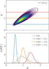 |
Fig. 1 A simple synthetic example of a joint distribution on the couple (Θ, Y). Top: contour levels of the PDF of the joint distribution with lognormal marginals and a clear correlation. Three observed values are indicated with horizontal lines. Bottom: comparison of the distribution on Θ before any observation (prior, in dashed black) and for the three y values (conditional distributions, in colors). |
2.4 Differential entropy for continuous random variables
As was introduced in Sect. 2.1, this work relies on continuous random variables, namely subsets of lines Y(s) ∈ ℝK and physical parameters Θ ∈ ℝD; for example, visual extinction or incident UV radiative field intensity. For continuous random variables, the information theory notion of entropy is generalized with the differential entropy (Cover & Thomas 2006, chapter 8):
![$\[h(\Theta)=\mathbb{E}_{\Theta}\left[-\log _2 \pi(\Theta)\right]=-\int\left[\log _2 \pi(\boldsymbol{\theta})\right] ~\pi(\boldsymbol{\theta}) ~\mathrm{d} \boldsymbol{\theta},\]$](/articles/aa/full_html/2024/11/aa51588-24/aa51588-24-eq10.png) (4)
(4)
with π(θ) the PDF of Θ. The differential entropy h (Θ) is the limit of the discrete entropy H of a quantized variable ΘΔ, where Δ is a quantization step (Cover & Thomas 2006, theorem 8.3.1)
![$\[h(\Theta)=\lim _{\Delta \rightarrow 0} H\left(\Theta^{\Delta}\right)+\log _2 \Delta.\]$](/articles/aa/full_html/2024/11/aa51588-24/aa51588-24-eq11.png) (5)
(5)
Unlike the finite case, the differential entropy can take negative values, as log2 Δ < 0 when Δ < 1. Table 2 lists the differential entropy formulae of a few common parametric distributions. For instance, the entropy of a Gaussian distribution only depends on its variance and not on its mean. The entropy of a uniform distribution on a compact set is the logarithm of the set volume.
For the example from Sect. 2.2, using the lognormal formula from Table 2, the uncertainty on Θ before any observation is h (Θ) = 0.07 bits. This corresponds to the uncertainty contained in a uniform distribution on an interval of size 20.07 = 1.05, or in a Gaussian distribution of standard deviation σ = 0.25.
The entropy can also be computed for couples of random variables. For instance, when considering the problem of inferring Θ from Y(s), we can now introduce the differential entropy on the couple (Θ, Y(s)) that is defined as
![$\[h\left(\Theta, Y^{(s)}\right)=\mathbb{E}_{\Theta, Y^{(s)}}\left[-\log _2 \pi\left(\Theta, Y^{(s)}\right)\right]\]$](/articles/aa/full_html/2024/11/aa51588-24/aa51588-24-eq12.png) (6)
(6)
![$\[=-\int\left[\log _2 \pi\left(\boldsymbol{\theta}, \mathbf{y}^{(s)}\right)\right] \pi\left(\boldsymbol{\theta}, \mathbf{y}^{(s)}\right) \mathrm{d} \boldsymbol{\theta} \mathrm{~d} \mathbf{y}^{(s)},\]$](/articles/aa/full_html/2024/11/aa51588-24/aa51588-24-eq13.png) (7)
(7)
where π(θ, y(s)) is the joint PDF of the couple (Θ, Y(s)).
Differential entropy for a few common distributions.
2.5 Conditional differential entropy: Effects of observations
Observations are performed in order to infer physical parameters Θ. In Sect. 2.1, we described observations that include noise. Observing a vector y(s) thus does not permit one to determine the physical conditions Θ with infinite precision. However, it can reduce the uncertainty on the physical parameters Θ.
The conditional differential entropy h (Θ| Y(s)) quantifies the expected uncertainty remaining on Θ when Y(s) is known; that is, after a future observation. It is defined as
![$\[h\left(\Theta \mid Y^{(s)}\right)=\mathbb{E}_{\Theta, Y^{(s)}}\left[-\log _2 \pi\left(\Theta \mid Y^{(s)}\right)\right]\]$](/articles/aa/full_html/2024/11/aa51588-24/aa51588-24-eq18.png) (8)
(8)
![$\[=-\int\left[\log _2 \pi\left(\boldsymbol{\theta} \mid \mathbf{y}^{(s)}\right)\right] \pi\left(\boldsymbol{\theta}, \mathbf{y}^{(s)}\right) \mathrm{d} \boldsymbol{\theta} \mathrm{~d} \mathbf{y}^{(s)}.\]$](/articles/aa/full_html/2024/11/aa51588-24/aa51588-24-eq19.png) (9)
(9)
The conditional differential entropy h Θ | Y(s)) is a mean value characterizing all the possible joint realizations of the observations and the physical parameters. It is therefore not a function of a specific realization y(s) of the Y(s) random variable. Instead, it quantifies how a future observation y(s) of Y(s) would affect the uncertainty on the physical conditions Θ on average. This average is computed with respect to the joint distribution of physical parameters Θ and observations Y(s). The conditional differential entropy can thus be evaluated prior to any observation and estimation. It can be shown that
![$\[h\left(\Theta \mid Y^{(s)}\right)=h\left(\Theta, Y^{(s)}\right)-h\left(Y^{(s)}\right).\]$](/articles/aa/full_html/2024/11/aa51588-24/aa51588-24-eq20.png) (10)
(10)
This means that the remaining uncertainty on Θ, once Y(s) is known, is the information jointly carried by both Θ and Y(s) minus the information brought by Y(s) alone. In other words, knowing Y(s) provides additional information to estimate Θ. This implies that the conditional differential entropy is always lower or equal to the differential entropy:
![$\[h\left(\Theta \mid Y^{(s)}\right) \leq h(\Theta).\]$](/articles/aa/full_html/2024/11/aa51588-24/aa51588-24-eq21.png) (11)
(11)
This inequality becomes an equality if and only if Θ and Y(s) are independent. This can occur for instance in the low S/N regime, when additive noise completely dominates the line intensity. Conversely, if there exists a bijection between Θ and Y(s) (e.g., in the absence of noise and with a bijective f in Eq. (1)), then h (Θ|Y(s)) is equal to −∞.
The example of Sect. 2.2 shows how different values of Y yield different uncertainties on Θ. The lower panel in Fig. 1 shows that, among the three observed y, lower values of y lead to a tighter distribution and thus to lower uncertainties on Θ. The remaining uncertainty on Θ is −2.01, −1.11, or −0.58 bits after observing y = 0.5, 1, or 1.5, respectively. The conditional differential entropy h (Θ | Y) averages over all possible observations y. Using Eq. (9)) and the lognormal formulae from Table 2, in this case, h (Θ | Y) = −1.08 − 0.07 = −1.15 bits. The latter value is the mean uncertainty on Θ when observing Y, averaged on all possible values of Y(s).
The differential entropy h (Θ | Y) is related to the error in estimating Θ from the Y data, and in particular to the root mean squared error. For instance, in an estimation procedure, decreasing the entropy by 1 bit improves the precision4 by a factor of two in the Gaussian case. Appendix B illustrates the notion of a difference of one bit between two probability distributions. An interpretation valid in the general case will be presented in the second paper of this series.
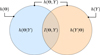 |
Fig. 2 Venn diagram representation of the differential entropy h (Θ) (and h (Y)) of the conditional differential entropy h (Θ|Y) (and h (Y|Θ)), and of the mutual information I (Θ, Y). |
2.6 Mutual information
The mutual information I (Θ, Y(s)) (Cover & Thomas 2006, sect. 8.6) is often preferred for a simpler interpretation. It quantifies the information on Θ that is gained by knowing Y(s):
![$\[I\left(\Theta, Y^{(s)}\right)=h(\Theta)-h\left(\Theta \mid Y^{(s)}\right).\]$](/articles/aa/full_html/2024/11/aa51588-24/aa51588-24-eq22.png) (12)
(12)
Figure 2 shows a Venn diagram that illustrates the relationships between differential entropy, conditional differential entropy and mutual information. It illustrates Eq. (10) and (12).
Mutual information is always positive, as implied by Eq. (11). A high mutual information indicates that knowing Y(s) considerably lowers the uncertainty on Θ. If we consider different distributions of a given physical parameter (e.g., corresponding to different physical regimes), represented by different random variables Θ, the mutual information is delicate to compare as it depends on the initial uncertainty. Indeed, it is easier to provide information on the physical parameter if the latter is highly uncertain than if it is already precisely constrained.
The mutual information is invariant to invertible transformations of Θ or Y(s) separately. Its value is thus identical whether integrated intensities are considered in linear scale, logarithm scale or with a asinh transformation as in Gratier et al. (2017). Conversely, non-bijective transformations result in a loss of information, and thus decrease the mutual information. For instance, an integrated intensity is obtained with a non-invertible integration of the associated line profile, and thus contains less information.
In the example from Sect. 2.2, the value of mutual information is I (Θ, Y) = 1.22 bits; that is, the difference between h (Θ) = 0.07 bits and h (Θ | Y) = −1.15 bits. This means that observing Y increases the information on Θ by 1.22 bits on average. Equivalently, observing Y improves the precision on Θ by a factor of 21.22 ≃ 2.3, on average.
2.7 Finding the lines that best constrain physical parameters
Constraining a physical parameter is commonly defined as reducing the uncertainty associated with it. In information theory, this uncertainty is quantified by the conditional entropy h (Θ | Y). The best subset sK of K lines for a given physical regime is then the solution of the discrete optimization problem
![$\[s_K=\underset{s \in \mathcal{S}_K}{\arg \min } ~h\left(\Theta \mid Y^{(s)}\right),\]$](/articles/aa/full_html/2024/11/aa51588-24/aa51588-24-eq23.png) (13)
(13)
with SK the set of all possible subsets of K lines. Using the relationship h (Θ | Y(s)) = h (Θ) − I (Θ, Y(s)), the problem can be restated as maximizing mutual information such that an equivalent formulation is
![$\[s_K=\underset{s \in \mathcal{S}_K}{\arg \max } ~I\left(\Theta, Y^{(s)}\right).\]$](/articles/aa/full_html/2024/11/aa51588-24/aa51588-24-eq24.png) (14)
(14)
This optimization problem is solved by comparing mutual information values for all subsets s ∈ SK. The entropy and mutual information values are heavily dependent on the choice of prior on the Θ distribution. Solving Eq. (14) requires the ability to evaluate the mutual information for each pair (Θ, Y(s)). In real-life applications, the shape of the distribution on (Θ, Y(s)) can be complex or unknown. In such cases, the mutual information does not have a simple closed-form expression, unlike the simple cases listed in Table 2. It then needs to be evaluated numerically with a Monte Carlo estimator ![$\[\widehat{I}_{N}\left(\Theta, Y^{(s)}\right)\]$](/articles/aa/full_html/2024/11/aa51588-24/aa51588-24-eq25.png) from a set of N pairs (
from a set of N pairs (![$\[\left\boldsymbol{\theta}_{n}, \mathbf{y}_{n}^{(s)}\right.\]$](/articles/aa/full_html/2024/11/aa51588-24/aa51588-24-eq26.png) ).
).
The Monte Carlo estimator ![$\[\widehat{I}_{N}\left(\Theta, Y^{(s)}\right)\]$](/articles/aa/full_html/2024/11/aa51588-24/aa51588-24-eq27.png) considered in the remainder of this work is the “Kraskov estimator” (Kraskov et al. 2004). This estimator does not make assumptions on the shape of the joint distribution on Θ, Y(s). It can thus capture both linear and nonlinear relationships between lines Y(s) and physical parameters Θ. See Appendix C for more details on this estimator and the derivation of the associated error bars.
considered in the remainder of this work is the “Kraskov estimator” (Kraskov et al. 2004). This estimator does not make assumptions on the shape of the joint distribution on Θ, Y(s). It can thus capture both linear and nonlinear relationships between lines Y(s) and physical parameters Θ. See Appendix C for more details on this estimator and the derivation of the associated error bars.
The set of N pairs ![$\[\left(\boldsymbol{\theta}_{n}, \mathbf{y}_{n}^{(s)}\right)\]$](/articles/aa/full_html/2024/11/aa51588-24/aa51588-24-eq28.png) can be made up of real observations or simulated observations. This paper considers simulated observation. The considered approach involves 3 steps: i) drawing N physical parameters vectors θn from a distribution π(θ), ii) evaluating the ISM model f on each physical parameter θn for all lines, iii) applying the noise model 𝒜 to obtain simulated noisy observations yn. In the second paper of this series, the method is applied to a set of real observations.
can be made up of real observations or simulated observations. This paper considers simulated observation. The considered approach involves 3 steps: i) drawing N physical parameters vectors θn from a distribution π(θ), ii) evaluating the ISM model f on each physical parameter θn for all lines, iii) applying the noise model 𝒜 to obtain simulated noisy observations yn. In the second paper of this series, the method is applied to a set of real observations.
3 Application to simulated photodissociation regions observed with IRAM 30m EMIR
Mutual information, introduced in Sect. 2, allows one to evaluate the constraining power of ionic, atomic and molecular lines. The general method presented in Sect. 2.7 allows one to determine which lines are the most informative to constrain the physical properties of an emitting object. This method can be applied to any astrophysical model that computes line intensities from a few input parameters; for example, radiative transfer codes simulating interstellar clouds, emission lines from protoplanetary disks, or stellar spectra synthesis models. It can also be applied to any other spectroscopic observations.
In this section, we introduce two synthetic cases of PDRs. In both cases, we resort to a fast and accurate emulator of the Meudon PDR code, and simulate noise using the characteristics of the EMIR receiver at the IRAM 30m. With these two cases, we shall show how mutual information can provide insights for ISM physics understanding, and apply the proposed line selection method. As the results of the proposed approach heavily depend on various aspects (e.g., the instrument properties, the integration time, or the observed environment), we depict these two cases in detail.
The Meudon PDR code is first presented along with a fast and accurate emulator. Then, the details of the generation of the sets of models are introduced, namely, the physical parameter distribution and the observation simulator. Overall, we consider two situations with distinct physical parameter distributions.
3.1 The Meudon PDR code
The Meudon PDR code5 (Le Petit et al. 2006) is a one-dimensional stationary code that simulates a PDR; that is, neutral interstellar gas illuminated with a stellar radiation field. It permits the investigation of the radiative feedback of a newborn star on its parent molecular cloud, but it can also be used to simulate a variety of other environments.
The user specifies physical conditions such as the thermal pressure, Pth, the intensity of the incoming UV radiation field, G0 (scaling factor applied to the Mathis et al. 1983 standard field), and the depth of the slab of gas expressed in visual extinctions, ![$\[A_{V}^{\text {tot }}\]$](/articles/aa/full_html/2024/11/aa51588-24/aa51588-24-eq29.png) . The code then solves multiphysics coupled balance equations of radiative transfer, thermal balance, and chemistry for each point of an adaptive spatial grid of a one-dimensional slab of gas. First, the code solves the radiative transfer equation, considering absorption in the continuum by dust and in the lines of key atoms and molecules such as H and H2 (Goicoechea & Le Bourlot 2007). Then, from the specific intensity of the radiation field, it computes the gas and grain temperatures by solving the thermal balance. The code accounts for a large number of heating and cooling processes, in particular photoelectric and cosmic ray heating, and line cooling. Finally, the chemistry is solved, providing the densities of about 200 species at each position. About 3000 reactions are considered, both in the gas phase and on the grains. The chemical reaction network was built combining different sources including data from the KIDA database (Wakelam et al. 2012) and the UMIST database (McElroy et al. 2013) as well as data from articles. For key photoreactions, cross sections are taken from Heays et al. (2017) and from Ewine van Dishoeck’s photodissociation and photoionization database. The successive resolution of these three coupled aspects is iterated until a global stationary state is reached.
. The code then solves multiphysics coupled balance equations of radiative transfer, thermal balance, and chemistry for each point of an adaptive spatial grid of a one-dimensional slab of gas. First, the code solves the radiative transfer equation, considering absorption in the continuum by dust and in the lines of key atoms and molecules such as H and H2 (Goicoechea & Le Bourlot 2007). Then, from the specific intensity of the radiation field, it computes the gas and grain temperatures by solving the thermal balance. The code accounts for a large number of heating and cooling processes, in particular photoelectric and cosmic ray heating, and line cooling. Finally, the chemistry is solved, providing the densities of about 200 species at each position. About 3000 reactions are considered, both in the gas phase and on the grains. The chemical reaction network was built combining different sources including data from the KIDA database (Wakelam et al. 2012) and the UMIST database (McElroy et al. 2013) as well as data from articles. For key photoreactions, cross sections are taken from Heays et al. (2017) and from Ewine van Dishoeck’s photodissociation and photoionization database. The successive resolution of these three coupled aspects is iterated until a global stationary state is reached.
The code yields 1D-spatial profiles of density of many chemical species and of temperature of both grains and gas as a function of depth in the PDR. From these spatial profiles, it also computes the line integrated intensities emerging from the cloud that can be compared to observations. As of version 7 (released in 2024), thousands line intensities are predicted from species such as H2, HD, H2O, C+, C, CO, 13CO, C18O, 13C18O, SO, HCO+, OH, HCN, HNC, CH+, CN or CS. Although the Meudon PDR code was primarily designed for PDRs, it can also simulate the physics and chemistry of a wide variety of other environments such as diffuse clouds, nearby galaxies, damped Lyman alpha systems and circumstellar disks.
3.2 Neural network-based emulation of the model
The numerical estimation of the mutual information requires drawing thousands of physical parameters θn and evaluating the associated integrated intensities fℓ(θn) in order to achieve satisfying precisions for line ranking (see, e.g., the experiment from Appendix C). A single full run of the Meudon PDR code is computationally intensive and typically lasts a few hours for one input vector θ. Generating such a large set of models with the original code would therefore be very slow. This is a recurrent limitation of comprehensive ISM models that received a lot of attention recently. The most common solution is to derive a fast approximation of a heavy ISM code using an interpolation method (Galliano 2018; Wu et al. 2018; Ramambason et al. 2022), a machine learning algorithm (Bron et al. 2021; Smirnov-Pinchukov et al. 2022) or a neural network (de Mijolla et al. 2019; Holdship et al. 2021; Grassi et al. 2022; Palud et al. 2023).
In this work, we use the fast, light (memory-wise) and accurate neural network approximation of the Meudon PDR code proposed in Palud et al. (2023). This approximation is valid for ![$\[\log _{10} P_{\text {th }} \in[5,9], \log _{10} G_{0} \in[0,5], \log _{10} A_{V}^{\text {tot }} \in\left[0, \log _{10}(40)\right]\]$](/articles/aa/full_html/2024/11/aa51588-24/aa51588-24-eq30.png) . As neural networks can process multiple inputs at once in batches, the evaluation of 103 input vectors θ with this approximation lasts about 10 ms on a personal laptop. With the original code, performing that many evaluations would require about a week using high performance computing; that is, about 60 million times longer even with much more computing power. For the lines studied in this paper, the emulator results in an average error of about 3.5% on the validity intervals, which is three times lower than the average calibration error at the IRAM 30m. The error on mutual information values due to using the emulator instead of the original code is thus negligible. For this reason and to simplify notation in the remainder of this paper, we denote f this neural network approximation.
. As neural networks can process multiple inputs at once in batches, the evaluation of 103 input vectors θ with this approximation lasts about 10 ms on a personal laptop. With the original code, performing that many evaluations would require about a week using high performance computing; that is, about 60 million times longer even with much more computing power. For the lines studied in this paper, the emulator results in an average error of about 3.5% on the validity intervals, which is three times lower than the average calibration error at the IRAM 30m. The error on mutual information values due to using the emulator instead of the original code is thus negligible. For this reason and to simplify notation in the remainder of this paper, we denote f this neural network approximation.
3.3 Generating sets of models
To demonstrate the power of the approach presented in Sect. 2.7, we apply it to a simulation of lines observed by the EMIR (Eight MIxer Receiver) heterodyne receiver. This receiver operates in the 3 mm, 2 mm, 1.3 mm and 0.9 mm bands at the IRAM 30m telescope (Carter et al. 2012). This application also includes the far infrared (FIR) [CI] 370 μm, [CI] 609 μm and [CII] 157 μm lines. These three lines are relevant for this application as their behavior is well understood within PDRs (Kaufman et al. 1999), especially their dependency on G0.
However, choosing which lines to include in the study is not the only critical choice. Indeed, the values of mutual information and therefore the result of the optimization problem heavily depend on the prior distribution π (θ) on the physical parameters – which, in particular, specifies the expected physical regime – and the observation simulator.
Summary of the parameter distribution for the two studied situations.
3.3.1 Physical regimes and distribution of parameters
The distribution, π(θ), on physical parameters represents the expected proportions of pixels in each physical regime within an observation. This distribution has a crucial influence on ISM model predictions and thus on the mutual information values and line ranking. It should therefore be carefully chosen. In this paper, we study two situations, summarized in Table 3.
First, we consider a loguniform distribution over the whole validity space of the emulated ISM model. As this option does not favor any physical regime, it is a common choice in ISM studies (see, e.g., Behrens et al. 2022; Blanc et al. 2015; Thomas et al. 2018; Holdship et al. 2018; Joblin et al. 2018). In other words, it assumes that all kinds of environments are equally likely, which is not the case in general in observed environments. However, choosing the distribution of maximal entropy on log ![$\[A_{V}^{\text {tot }}\]$](/articles/aa/full_html/2024/11/aa51588-24/aa51588-24-eq33.png) and log G0 averages the lines informativity over different physical conditions without introducing any bias.
and log G0 averages the lines informativity over different physical conditions without introducing any bias.
Second, we consider a physical environment similar to the Horsehead pillar. Real life observations of molecular clouds such as Orion B (Pety et al. 2017) or OMC-1 (Goicoechea et al. 2019) typically contain more pixels corresponding to translucent gas than dense cores. This is due to the fact that translucent gas fills a larger volume than dense cores in a galaxy. To incorporate this physical knowledge in our study, we fit a power law distribution on ![$\[A_{V}^{\text {tot }}\]$](/articles/aa/full_html/2024/11/aa51588-24/aa51588-24-eq34.png) and G0 (Hennebelle & Falgarone 2012). The associated exponents are adjusted on ORION-B data, following the method described in Clauset et al. (2009).
and G0 (Hennebelle & Falgarone 2012). The associated exponents are adjusted on ORION-B data, following the method described in Clauset et al. (2009).
For a given situation, one can choose to simulate observations only within a particular environment (e.g., translucent clouds with ![$\[3 \leq A_{V}^{\text {tot }} \leq 6\]$](/articles/aa/full_html/2024/11/aa51588-24/aa51588-24-eq35.png) ). This physical a priori can then be used to refine the results. In practice, any available physical knowledge is useful to integrate into the parameters prior distribution or the observation simulator.
). This physical a priori can then be used to refine the results. In practice, any available physical knowledge is useful to integrate into the parameters prior distribution or the observation simulator.
3.3.2 Observation simulator
Eq. (1) involves an abstract noise model 𝒜. In this experiment, the considered noise model combines two sources of noise for each of the considered lines: one additive Gaussian and one multiplicative lognormal. The additive noise corresponds to thermal noise, whereas the multiplicative noise corresponds to the calibration uncertainty. For all lines, we compute the integrated line intensity over a velocity range of 10 km s−1. Overall, for the nth element of the dataset (1 ≤ n ≤ N) and the ℓth line, the observation simulator reads
![$\[y_{n \ell}=\varepsilon_{n \ell}^{(m)} f_{\ell}\left(\boldsymbol{\theta}_n\right)+\varepsilon_{n \ell}^{(a)},\]$](/articles/aa/full_html/2024/11/aa51588-24/aa51588-24-eq36.png) (15)
(15)
![$\[\left\{\begin{array}{l}\varepsilon_{n \ell}^{(a)} \sim \mathcal{N}\left(0, \sigma_{a, \ell}^2\right), \\\varepsilon_{n \ell}^{(m)} \sim \log \mathcal{N}\left(-\frac{\sigma_m^2}{2}, \sigma_m^2\right).\end{array}\right.\]$](/articles/aa/full_html/2024/11/aa51588-24/aa51588-24-eq37.png)
The standard deviation of the multiplicative noise, σm, was set so that a 1σ uncertainty interval corresponds to a given percentage for the calibration error. For instance, a 5% calibration error leads to σm = log(1.05). For EMIR lines, this percentage is assumed to be identical for the lines within the same band: 5% at 3 mm, 7.5% at 2 mm and 10% at both 1.3 mm and 0.9 mm. For the time being, the additive noise RMS levels ![$\[\sigma_{a, \ell}^{2}\]$](/articles/aa/full_html/2024/11/aa51588-24/aa51588-24-eq38.png) are set according to the ORION-B Large Program observations (Einig et al. 2023). To do this, we resort to the IRAM 30m software that delivers the telescope sensitivity as a function of frequency. We consider standard weather conditions at Pico Veleta and set the integration time per pixel to 24 seconds. An increase in the integration time would amount to dividing the additive noise RMS σa,ℓ by the square root of the increase factor.
are set according to the ORION-B Large Program observations (Einig et al. 2023). To do this, we resort to the IRAM 30m software that delivers the telescope sensitivity as a function of frequency. We consider standard weather conditions at Pico Veleta and set the integration time per pixel to 24 seconds. An increase in the integration time would amount to dividing the additive noise RMS σa,ℓ by the square root of the increase factor.
For FIR lines, we assume that the [CII] line is observed with SOFIA and has an additive noise RMS of 2.25 K per channel in addition of a 5% calibration error (Risacher et al. 2016; Pabst et al. 2017). We also assume that both [CI] lines are observed at Mount Fuji observatory with an RMS of 0.5 K and a 20% calibration error (Ikeda et al. 2002). For all lines, the integration range is assumed to be 10 km s−1.
Important observational effects such as the beam dilution or the cloud geometry are disregarded in Eq. (15). As a consequence, we propose an alternative observation simulator that accounts for such observational effects through a scaling factor, κ. This factor is assumed common to all lines such that
![$\[\forall 1 \leq \ell \leq L, \quad y_{n \ell}=\varepsilon_{n \ell}^{(m)} \kappa_n f_{\ell}\left(\boldsymbol{\theta}_n\right)+\varepsilon_{n \ell}^{(a)}.\]$](/articles/aa/full_html/2024/11/aa51588-24/aa51588-24-eq39.png) (17)
(17)
Beam dilution decreases line intensities, while an edge-on geometry increases line intensities compared to a face-on orientation. Therefore, we consider that log10 κ follows a uniform distribution on [−0.5, 0.5], which seems realistic when looking at extended sources like Orion B. See Sheffer & Wolfire (2013) for a more thorough description of this scaling parameter. This approach of including these effects in the observation simulator is a first order approximation. In particular, the hypothesis of a shared κ among all lines is only valid for optically thin lines.
In the remainder of this work, unless explicitly specified, the considered observation simulator is Eq. (15) – without the κ term.
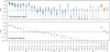 |
Fig. 3 Violin plots of the S/N of the spectral lines considered in this study, with the S/N defined as fℓ(θ)/σa,ℓ. The EMIR lines are displayed in blue on the left, while the [CI] and [CII] lines are shown in orange on the right. Top: S/N distributions for a loguniform distribution on the full validity intervals on the physical parameters. The considered line filter only keeps lines that have a 99% percentile S/N greater than 3. This threshold is indicated with the horizontal dashed black line, and the actual 99% percentile S/N is shown with a short black line for each line. Bottom: S/N distributions in an environment similar to the Horsehead pillar, for the same lines. The lines are ranked by decreasing median S/N, indicated in red. |
3.3.3 Considered lines
In the simulated observations, the intensity of some lines is completely dominated by the additive noise. The intensity of these lines is thus nearly independent of physical parameters Θ and has a near-zero mutual information with them. To avoid useless mutual information evaluations, we filter out uninformative lines based on their S/N. We thus only study lines that have an S/N greater than 3 for at least 1% of the full parameter space. In total, L = 36 lines are considered: 33 millimeter lines – with multiple lines in each of the four frequency bands – and the 3 lines from atomic and ionized carbon. For lines with hyperfine structure, the Meudon PDR code considers the transitions independently. To simplify our systematic comparison, only the brightest transition is retained. Summing the integrated intensities of all the transitions might lead to a more realistic approximation of the overall line.
Figure 3 shows the distribution of S/N level across the considered parameter space for each of the L = 36 considered lines. These lines include the first three low-J transitions of 12CO, 13CO, C18O, the first four of HCO+, five of the first seven of 12CS, six lines of 12CN, two lines of HNC, three lines of HCN, and four lines of C2H. The first row contains S/N violin plots for a loguniform distribution on the validity intervals for the physical parameters θ. It shows that all the considered lines can have very low S/Ns for some regimes of the explored physical parameter space. Below an S/N of 1–2, signal becomes difficult to distinguish from noise. The second row contains S/N violin plots for a parameter space restricted to the range found in the Horse-head pillar. In this use case, the line S/Ns cover fewer orders of magnitude. For instance, in this case, the lines corresponding to the last 18 blue violin histogram have a very low S/N, and are thus unlikely to be informative. This shows that the subset of informative lines could be further reduced in this case. While dedicated filters could be performed for each use case, we maintain the same subset of L = 36 lines in all the studied use cases to simplify interpretations.
The considered noise properties of the EMIR receiver, of SOFIA, and of the Mt. Fuji observatory are not identical for all lines. For instance, Fig. 3 shows similar range of S/N values for the ground state transition of 12CO and 13CO. This might be surprising, since the ground state transition of 12CO is known to be brighter than that of 13CO (Pety et al. 2017). In this case, the additive noise standard deviation σa,ℓ of 12CO(l − 0) is much larger than that of 13CO (1 − 0) because 12CO (1 − 0) is located on the upper limit of the band at 3 mm. This results in their comparable S/Ns. The same observation can be done for the [CII] line: although this line is usually much brighter than all the other considered lines, its S/N is close to 1 due to the considered noise properties of SOFIA. Appendix G provides the full list of considered lines and the associated noise characteristics.
4 Simulation results and general applications
In this section, we show general results and insights of our approach in the considered setting. To do so, we evaluate the mutual information between the integrated intensity of a few ISM tracers with either the visual extinction ![$\[A_{V}^{\text {tot }}\]$](/articles/aa/full_html/2024/11/aa51588-24/aa51588-24-eq40.png) or the UV radiative field G0. First, we consider the impact of integration time, and thus of S/N, on the mutual information value. Second, we show how the mutual information between line intensities and
or the UV radiative field G0. First, we consider the impact of integration time, and thus of S/N, on the mutual information value. Second, we show how the mutual information between line intensities and ![$\[A_{V}^{\text {tot }}\]$](/articles/aa/full_html/2024/11/aa51588-24/aa51588-24-eq41.png) or G0 changes with the values of
or G0 changes with the values of ![$\[A_{V}^{\text {tot }}\]$](/articles/aa/full_html/2024/11/aa51588-24/aa51588-24-eq42.png) and G0, in order to better understand the physical processes that control the informativity of these lines. Third, we illustrate how combining different lines can impact their mutual information with
and G0, in order to better understand the physical processes that control the informativity of these lines. Third, we illustrate how combining different lines can impact their mutual information with ![$\[A_{V}^{\text {tot }}\]$](/articles/aa/full_html/2024/11/aa51588-24/aa51588-24-eq43.png) .
.
The goal of this section is to demonstrate the approach potential and consistency with already known results. Therefore, we restrict the analysis to two variables – for visualization purposes – and choose the two variables for which astrophysicists have the best intuition, namely the visual extinction ![$\[A_{V}^{\text {tot }}\]$](/articles/aa/full_html/2024/11/aa51588-24/aa51588-24-eq44.png) or the UV field intensity G0. In particular, we do not present mutual information values for the thermal pressure, Pth, although the proposed approach and code can perform these computations. In addition, we restrict the experiment to univariate physical parameters as this greatly simplifies physical interpretations. In other words, we compute mutual information for only one physical parameter (
or the UV field intensity G0. In particular, we do not present mutual information values for the thermal pressure, Pth, although the proposed approach and code can perform these computations. In addition, we restrict the experiment to univariate physical parameters as this greatly simplifies physical interpretations. In other words, we compute mutual information for only one physical parameter (![$\[\leftA_{V}^{\text {tot }}\right.\]$](/articles/aa/full_html/2024/11/aa51588-24/aa51588-24-eq45.png) or G0) at a time, although the proposed approach and code can evaluate the mutual information for both
or G0) at a time, although the proposed approach and code can evaluate the mutual information for both ![$\[A_{V}^{\text {tot }}\]$](/articles/aa/full_html/2024/11/aa51588-24/aa51588-24-eq46.png) and G0 simultaneously. Analyzing less understood physical parameters such as the thermal pressure, Pth, or evaluating the mutual information for multiple physical parameters at once is left for future work.
and G0 simultaneously. Analyzing less understood physical parameters such as the thermal pressure, Pth, or evaluating the mutual information for multiple physical parameters at once is left for future work.
4.1 Signal-to-noise ratio for a line to deliver its full physical potential
The mutual information I (Θ, Yℓ) between a line intensity Yℓ and a given physical parameter Θ not only depends on the intrinsic physical sensitivity of the lines with the considered physical parameter, but also on the mean S/N of the studied observation. For a given line, the mean S/N is influenced by 1) the corresponding species and its quantum transition, 2) the physical conditions (e.g., kinetic temperature and volume density), and 3) the integration time with an observatory to reach a given noise level6.
Figure 4 shows the influence of the mean S/N (left column) and the integration time (right column) on ![$\[I\left(A_{V}^{\text {tot }}, Y_{\ell}\right)\]$](/articles/aa/full_html/2024/11/aa51588-24/aa51588-24-eq49.png) for several transitions of HCO+, HCN, and HNC. The considered distribution π(θ) on physical parameters is the one similar to the Horsehead Nebula (see Table 4), restricted to filamentary gas (
for several transitions of HCO+, HCN, and HNC. The considered distribution π(θ) on physical parameters is the one similar to the Horsehead Nebula (see Table 4), restricted to filamentary gas (![$\[6 \leq A_{V}^{\text {tot }} \leq 12\]$](/articles/aa/full_html/2024/11/aa51588-24/aa51588-24-eq50.png) ). The dotted vertical line in the right column shows the typical integration time per pixel in the ORION-B dataset. For each line, the mutual information varies with mean S/N and time following an S-shape. Low S/N values lead to zero mutual information because the line intensity is dominated by additive noise. The inflection point of the S-curve is located at S/N about 3. A given line reaches its full informativity potential when the curve starts to saturate; for instance at S/N ~ 10 for all lines in this case. For large S/N, the mutual information converges to a value that depends on the line microphysical characteristics. This value is finite because each
). The dotted vertical line in the right column shows the typical integration time per pixel in the ORION-B dataset. For each line, the mutual information varies with mean S/N and time following an S-shape. Low S/N values lead to zero mutual information because the line intensity is dominated by additive noise. The inflection point of the S-curve is located at S/N about 3. A given line reaches its full informativity potential when the curve starts to saturate; for instance at S/N ~ 10 for all lines in this case. For large S/N, the mutual information converges to a value that depends on the line microphysical characteristics. This value is finite because each ![$\[A_{V}^{\text {tot }}\]$](/articles/aa/full_html/2024/11/aa51588-24/aa51588-24-eq51.png) value is combined with many values of thermal pressure and UV illumination.
value is combined with many values of thermal pressure and UV illumination.
Using the proposed method, the integration time can be set to achieve a target mean S/N and mutual information. For instance, according to Fig. 4, ![$\[I\left(A_{V}^{\text {tot }}, Y_{\ell}\right)\]$](/articles/aa/full_html/2024/11/aa51588-24/aa51588-24-eq54.png) has already reached its maximum value for HCO+ (1–0) in the filamentary gas part of ORION-B dataset. An increase in the integration time would thus not increase the informativity of this line; in other words, it would not improve the precision in an estimation of
has already reached its maximum value for HCO+ (1–0) in the filamentary gas part of ORION-B dataset. An increase in the integration time would thus not increase the informativity of this line; in other words, it would not improve the precision in an estimation of ![$\[A_{V}^{\text {tot }}\]$](/articles/aa/full_html/2024/11/aa51588-24/aa51588-24-eq55.png) from HCO+ (1 − 0). Conversely, a 100-fold increase in the integration time would improve the mutual information for the HCN (1 − 0) and HNC (1 − 0) lines by 0.7 and 0.5 bits, respectively, and would lead to maximum precision in an estimation of
from HCO+ (1 − 0). Conversely, a 100-fold increase in the integration time would improve the mutual information for the HCN (1 − 0) and HNC (1 − 0) lines by 0.7 and 0.5 bits, respectively, and would lead to maximum precision in an estimation of ![$\[A_{V}^{\text {tot }}\]$](/articles/aa/full_html/2024/11/aa51588-24/aa51588-24-eq56.png) with these lines. Higher energy transitions of HCO+ could also be fully exploited with such an increase in the integration time. As a reference, the next generation of multibeam receivers currently foreseen in millimeter radio astronomy are expected to bring a 25-fold sensitivity improvement without increasing the integration time. The same figures of evolution of mutual information with the integration time for the 36 considered lines are available online7. They also display results with respect to the intensity of the UV radiative field G0 for translucent gas, filamentary gas and dense cores.
with these lines. Higher energy transitions of HCO+ could also be fully exploited with such an increase in the integration time. As a reference, the next generation of multibeam receivers currently foreseen in millimeter radio astronomy are expected to bring a 25-fold sensitivity improvement without increasing the integration time. The same figures of evolution of mutual information with the integration time for the 36 considered lines are available online7. They also display results with respect to the intensity of the UV radiative field G0 for translucent gas, filamentary gas and dense cores.
Figure 5 shows how ![$\[I\left(A_{V}^{\text {tot }}, Y_{\ell}\right)\]$](/articles/aa/full_html/2024/11/aa51588-24/aa51588-24-eq57.png) evolves with mean S/N for HCO+ (1 − 0) in the Horsehead Nebula (see Table 4) in three physical subregimes: translucent, filamentary, and dense core gas. The inflection point of the S-shape curve happens at an S/N of about 2, 5, and 10, respectively. Comparing the maximum value of mutual information for different regimes is hazardous here because the distribution of the
evolves with mean S/N for HCO+ (1 − 0) in the Horsehead Nebula (see Table 4) in three physical subregimes: translucent, filamentary, and dense core gas. The inflection point of the S-shape curve happens at an S/N of about 2, 5, and 10, respectively. Comparing the maximum value of mutual information for different regimes is hazardous here because the distribution of the ![$\[A_{V}^{\text {tot }}\]$](/articles/aa/full_html/2024/11/aa51588-24/aa51588-24-eq58.png) values (and thus the associated entropy) intrinsically depends on the studied physical regime. If a considered physical regime is broad, the mutual information between a given line and
values (and thus the associated entropy) intrinsically depends on the studied physical regime. If a considered physical regime is broad, the mutual information between a given line and ![$\[A_{V}^{\text {tot }}\]$](/articles/aa/full_html/2024/11/aa51588-24/aa51588-24-eq59.png) is likely to be higher than for another more localized regime even if the line is a better tracer of
is likely to be higher than for another more localized regime even if the line is a better tracer of ![$\[A_{V}^{\text {tot }}\]$](/articles/aa/full_html/2024/11/aa51588-24/aa51588-24-eq60.png) in the latter.
in the latter.
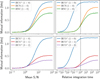 |
Fig. 4 Evolution of mutual information between the visual extinction |
![$\[A_{V}^{\text {tot }}\]$](/articles/aa/full_html/2024/11/aa51588-24/aa51588-24-eq47.png)
![$\[6 \leq A_{V}^{\text {tot }} \leq 12\]$](/articles/aa/full_html/2024/11/aa51588-24/aa51588-24-eq48.png)
Summary of the considered use cases.
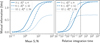 |
Fig. 5 Evolution of mutual information between the visual extinction |
![$\[A_{V}^{\text {tot }}\]$](/articles/aa/full_html/2024/11/aa51588-24/aa51588-24-eq52.png)
![$\[A_{V}^{\text {tot }}\]$](/articles/aa/full_html/2024/11/aa51588-24/aa51588-24-eq53.png)
4.2 The physical regimes in which a given line is informative
In this section, we show how mutual information can provide insights for ISM physics understanding. We showed in Fig. 5 that the mutual information between a physical parameter and a line intensity may significantly vary with the physical regime. The three large physical regimes used in the previous section were defined based on a priori astronomical knowledge. This may result in the omission of processes that occur in smaller and intermediate regimes. To overcome this issue, we introduce the notion of maps of the mutual information between a physical parameter (either ![$\[A_{V}^{\text {tot }}\]$](/articles/aa/full_html/2024/11/aa51588-24/aa51588-24-eq61.png) or G0) and line intensities as a function of both
or G0) and line intensities as a function of both ![$\[A_{V}^{\text {tot }}\]$](/articles/aa/full_html/2024/11/aa51588-24/aa51588-24-eq62.png) and G0. To do this, we filter the
and G0. To do this, we filter the ![$\[\left(\log _{10} A_{V}^{\text {tot }}, \log _{10} G_{0}\right)\]$](/articles/aa/full_html/2024/11/aa51588-24/aa51588-24-eq63.png) space with a sliding window of constant width, and consider loguniform distribution for each parameter. This width corresponds to a factor of two for
space with a sliding window of constant width, and consider loguniform distribution for each parameter. This width corresponds to a factor of two for ![$\[A_{V}^{\text {tot }}\]$](/articles/aa/full_html/2024/11/aa51588-24/aa51588-24-eq64.png) and a factor of about 5.2 for G0; that is, seven independent windows (without overlap) for each parameter. Then, we compute the mutual information between the line intensities, simulated with parameters in the sliding window, and either
and a factor of about 5.2 for G0; that is, seven independent windows (without overlap) for each parameter. Then, we compute the mutual information between the line intensities, simulated with parameters in the sliding window, and either ![$\[A_{V}^{\text {tot }}\]$](/articles/aa/full_html/2024/11/aa51588-24/aa51588-24-eq65.png) or G0. The additive noise in the simulated spectra corresponds to the integration time corresponding to the ORION-B observations; that is, 24 seconds per pixel. After describing the obtained maps of mutual information with
or G0. The additive noise in the simulated spectra corresponds to the integration time corresponding to the ORION-B observations; that is, 24 seconds per pixel. After describing the obtained maps of mutual information with ![$\[A_{V}^{\text {tot }}\]$](/articles/aa/full_html/2024/11/aa51588-24/aa51588-24-eq66.png) and G0, we explain them with maps of line intensities fℓ(θ).
and G0, we explain them with maps of line intensities fℓ(θ).
Here, the values of mutual information can be compared from one value of the ![$\[\left(A_{V}^{\text {tot }}, G_{0}\right)\]$](/articles/aa/full_html/2024/11/aa51588-24/aa51588-24-eq67.png) space to another because the sampling of this space is regular and the size of the sliding window is kept fixed. For the same reasons, the values of mutual information can also be compared from one line to another at a constant value of
space to another because the sampling of this space is regular and the size of the sliding window is kept fixed. For the same reasons, the values of mutual information can also be compared from one line to another at a constant value of ![$\[\left(A_{V}^{\text {tot }}, G_{0}\right)\]$](/articles/aa/full_html/2024/11/aa51588-24/aa51588-24-eq68.png) . Similarly, for a given line and value of
. Similarly, for a given line and value of ![$\[\left(A_{V}^{\text {tot }}, G_{0}\right), I\left(A_{V}^{\text {tot }}, Y_{\ell}\right)\]$](/articles/aa/full_html/2024/11/aa51588-24/aa51588-24-eq69.png) and I (G0, Yℓ) can be compared.
and I (G0, Yℓ) can be compared.
The considered prior π(θ) for each parameter is always loguniform in this section. In this very special case, a mutual information value of 1 bit for one physical parameter may be interpreted as a division of the standard deviation on the estimation of log ![$\[A_{V}^{\text {tot }}\]$](/articles/aa/full_html/2024/11/aa51588-24/aa51588-24-eq70.png) or log G0 by a factor of two. For instance, if the considered physical parameter is G0 and its mutual information I(log G0, y) with some line y is 1 bit, then the standard deviation of the conditional distribution π(log G0|y) is a factor of two lower than the one of the prior π(log G0). For more general prior distributions, this interpretation does not hold. The second paper of this series will provide an interpretation for the general case.
or log G0 by a factor of two. For instance, if the considered physical parameter is G0 and its mutual information I(log G0, y) with some line y is 1 bit, then the standard deviation of the conditional distribution π(log G0|y) is a factor of two lower than the one of the prior π(log G0). For more general prior distributions, this interpretation does not hold. The second paper of this series will provide an interpretation for the general case.
4.2.1 Relevance of individual ISM lines in constraining AVtot
We here wish to identify 1) which lines are the most relevant to estimate the visual extinction ![$\[A_{V}^{\text {tot }}\]$](/articles/aa/full_html/2024/11/aa51588-24/aa51588-24-eq71.png) , and 2) in which part of the
, and 2) in which part of the ![$\[\left(\log _{10} A_{V}^{\text {tot }}, \log _{10} G_{0}\right)\]$](/articles/aa/full_html/2024/11/aa51588-24/aa51588-24-eq72.png) space. Figure 6 shows maps of mutual information between the intensity of 20 individual lines and
space. Figure 6 shows maps of mutual information between the intensity of 20 individual lines and ![$\[A_{V}^{\text {tot }}\]$](/articles/aa/full_html/2024/11/aa51588-24/aa51588-24-eq73.png) . The size of the sliding window is shown in the 12CO map as a red rectangle while the range of the parameters within the Horsehead Nebula is represented with a white rectangle as a reference.
. The size of the sliding window is shown in the 12CO map as a red rectangle while the range of the parameters within the Horsehead Nebula is represented with a white rectangle as a reference.
Among the presented lines, the most informative ones for estimating ![$\[A_{V}^{\text {tot }}\]$](/articles/aa/full_html/2024/11/aa51588-24/aa51588-24-eq74.png) on average are the lines of 13CO and C18O followed by HCO+. The lines of 12CO, HCN, 12CS, and [CI] are also informative but on more restricted regions of the
on average are the lines of 13CO and C18O followed by HCO+. The lines of 12CO, HCN, 12CS, and [CI] are also informative but on more restricted regions of the ![$\[\left(A_{V}^{\text {tot }}, G_{0}\right)\]$](/articles/aa/full_html/2024/11/aa51588-24/aa51588-24-eq75.png) space. The J = 2–1 transitions have systematically lower mutual information with
space. The J = 2–1 transitions have systematically lower mutual information with ![$\[A_{V}^{\text {tot }}\]$](/articles/aa/full_html/2024/11/aa51588-24/aa51588-24-eq76.png) than the J = 1–0 transitions, which is due to a lower mean S/N – as shown on Fig. 3.
than the J = 1–0 transitions, which is due to a lower mean S/N – as shown on Fig. 3.
The three CO isotopologues give high values of the mutual information for most of the ![$\[\left(A_{V}^{\text {tot }}, G_{0}\right)\]$](/articles/aa/full_html/2024/11/aa51588-24/aa51588-24-eq77.png) space. For translucent clouds, the first two 13CO lines are the most informative. For dense clouds (large
space. For translucent clouds, the first two 13CO lines are the most informative. For dense clouds (large ![$\[A_{V}^{\text {tot }}\]$](/articles/aa/full_html/2024/11/aa51588-24/aa51588-24-eq78.png) ), the first two 13CO and C18O lines are the most informative. Finally, the fine structure [CI] lines and the ground state transition of 12CO have the highest mutual information values (even though these values are low) for the upper left corner, which corresponds to highly illuminated diffuse clouds.
), the first two 13CO and C18O lines are the most informative. Finally, the fine structure [CI] lines and the ground state transition of 12CO have the highest mutual information values (even though these values are low) for the upper left corner, which corresponds to highly illuminated diffuse clouds.
Although the ground state transitions of HCN and HNC are among the most informative lines in the high-![$\[A_{V}^{\text {tot }}\]$](/articles/aa/full_html/2024/11/aa51588-24/aa51588-24-eq79.png) low-G0 regime, we might have expected them to be even more informative in this physical regime since they are used as tracers of the dense cores. Their relatively low informativity is explained by low mean S/N values. As was shown in Fig. 4, the integration time is too short to exploit the full potential of these lines.
low-G0 regime, we might have expected them to be even more informative in this physical regime since they are used as tracers of the dense cores. Their relatively low informativity is explained by low mean S/N values. As was shown in Fig. 4, the integration time is too short to exploit the full potential of these lines.
We also observe that the mutual information with ![$\[A_{V}^{\text {tot }}\]$](/articles/aa/full_html/2024/11/aa51588-24/aa51588-24-eq82.png) is roughly constant with respect to the ratio
is roughly constant with respect to the ratio ![$\[G_{0}^{0.15} / A_{V}^{\text {tot }}\]$](/articles/aa/full_html/2024/11/aa51588-24/aa51588-24-eq83.png) for multiple lines. This ratio corresponds to a straight line in the
for multiple lines. This ratio corresponds to a straight line in the ![$\[\left(\log ~A_{V}^{\text {tot }}, \log ~G_{0}\right)\]$](/articles/aa/full_html/2024/11/aa51588-24/aa51588-24-eq84.png) space, and is displayed in Fig. 6. That is particularly clear for the 12CO, 13CO and C18O lines. In the upper left corner, where the
space, and is displayed in Fig. 6. That is particularly clear for the 12CO, 13CO and C18O lines. In the upper left corner, where the ![$\[G_{0}{ }^{0.15} / A_{V}^{\text {tot }}\]$](/articles/aa/full_html/2024/11/aa51588-24/aa51588-24-eq85.png) ratio is maximum, the mutual information is low. It increases as this ratio decreases, reaches a maximum and then decreases.
ratio is maximum, the mutual information is low. It increases as this ratio decreases, reaches a maximum and then decreases.
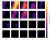 |
Fig. 6 Maps of mutual information of individual lines with the visual extinction in function of the actual visual extinction |
![$\[A_{V}^{\text {tot }}\]$](/articles/aa/full_html/2024/11/aa51588-24/aa51588-24-eq80.png)
![$\[G_{0}{ }^{0.15} / A_{V}^{\text {tot }}\]$](/articles/aa/full_html/2024/11/aa51588-24/aa51588-24-eq81.png)
4.2.2 Relevance of individual ISM lines in constraining G0
We now apply the same approach on the UV radiative field G0. Figure H.1 shows maps of mutual information between the intensity of the same 20 individual lines and G0. For most molecular lines except those of 12CO, the mutual information values are lower for G0 than for ![$\[A_{V}^{\text {tot }}\]$](/articles/aa/full_html/2024/11/aa51588-24/aa51588-24-eq86.png) . This indicates that the considered lines are more informative for
. This indicates that the considered lines are more informative for ![$\[A_{V}^{\text {tot }}\]$](/articles/aa/full_html/2024/11/aa51588-24/aa51588-24-eq87.png) than for G0; that is, that achieving a good precision on G0 is harder than on
than for G0; that is, that achieving a good precision on G0 is harder than on ![$\[A_{V}^{\text {tot }}\]$](/articles/aa/full_html/2024/11/aa51588-24/aa51588-24-eq88.png) . This result is consistent with Gratier et al. (2021).
. This result is consistent with Gratier et al. (2021).
For most of the ![$\[\left(A_{V}^{\text {tot }}, G_{0}\right)\]$](/articles/aa/full_html/2024/11/aa51588-24/aa51588-24-eq89.png) space, the most informative lines are [CII], 12CO lines and, to a lesser extent, [CI] lines. This is due to the fact that these five lines have a high mean S/N – with the considered noise properties – and are mostly emitted at the surface of the cloud, thus being sensitive to G0. For highly illuminated clouds (G0 ∈ [103, 104]), especially at low
space, the most informative lines are [CII], 12CO lines and, to a lesser extent, [CI] lines. This is due to the fact that these five lines have a high mean S/N – with the considered noise properties – and are mostly emitted at the surface of the cloud, thus being sensitive to G0. For highly illuminated clouds (G0 ∈ [103, 104]), especially at low ![$\[A_{V}^{\text {tot }}\]$](/articles/aa/full_html/2024/11/aa51588-24/aa51588-24-eq90.png) , the most informative transitions are the ones of HCO+. This is probably related to the fact that HCO+ is easily excited by electrons at the surface of the clouds. The mutual information of the HCN and HNC (1 − 0) intensities with G0 reach high values compared to other species (more than 0.8 bits) for G0 around 2 × 10³ and Av > 20. Finally, the 12CS transitions are the most informative in the upper right corner; that is, at both high
, the most informative transitions are the ones of HCO+. This is probably related to the fact that HCO+ is easily excited by electrons at the surface of the clouds. The mutual information of the HCN and HNC (1 − 0) intensities with G0 reach high values compared to other species (more than 0.8 bits) for G0 around 2 × 10³ and Av > 20. Finally, the 12CS transitions are the most informative in the upper right corner; that is, at both high ![$\[A_{V}^{\text {tot }}\]$](/articles/aa/full_html/2024/11/aa51588-24/aa51588-24-eq91.png) and G0.
and G0.
4.2.3 Underlying reasons
In order to better understand these mutual information maps, Fig. I.1 shows the integrated intensities fℓ(θ) as a function of ![$\[A_{V}^{\text {tot }}\]$](/articles/aa/full_html/2024/11/aa51588-24/aa51588-24-eq92.png) and G0. These predicted intensities are computed for Pth = 105 K cm−3, while the mutual information maps are computed for a pressure following a loguniform distribution on the [105, 5 × 10⁶] K cm−3 interval. However, they capture the main physical phenomena that drive mutual information. In a nutshell, this figure shows that to be informative for a physical parameter, a line needs both a good S/N and a large gradient with respect to the physical variable of interest. Since the gradient information might not be visible on Fig. I.1, Appendix I provides maps of the gradients of the log integrated intensities.
and G0. These predicted intensities are computed for Pth = 105 K cm−3, while the mutual information maps are computed for a pressure following a loguniform distribution on the [105, 5 × 10⁶] K cm−3 interval. However, they capture the main physical phenomena that drive mutual information. In a nutshell, this figure shows that to be informative for a physical parameter, a line needs both a good S/N and a large gradient with respect to the physical variable of interest. Since the gradient information might not be visible on Fig. I.1, Appendix I provides maps of the gradients of the log integrated intensities.
While the [CII] line (last row) is the brightest of all, it has near-zero mutual information with ![$\[A_{V}^{\text {tot }}\]$](/articles/aa/full_html/2024/11/aa51588-24/aa51588-24-eq93.png) in all regimes. As [CII] mostly exists at the surface of the cloud, the predicted integrated intensity almost does not depend on visual extinction. It only has a slight dependency at
in all regimes. As [CII] mostly exists at the surface of the cloud, the predicted integrated intensity almost does not depend on visual extinction. It only has a slight dependency at ![$\[A_{V}^{\text {tot }} \sim 1\]$](/articles/aa/full_html/2024/11/aa51588-24/aa51588-24-eq94.png) mag, which is the typical visual extinction where carbon becomes mostly neutral in a PDR (Röllig et al. 2007) (it is then included in molecules such as CO).
mag, which is the typical visual extinction where carbon becomes mostly neutral in a PDR (Röllig et al. 2007) (it is then included in molecules such as CO).
After the [CII] line, the two [CI] lines are the brightest. Their intensity first increases as ![$\[G_{0}{ }^{0.15} / A_{V}^{\text {tot }}\]$](/articles/aa/full_html/2024/11/aa51588-24/aa51588-24-eq95.png) decreases in the top left corner (shallow and highly illuminated clouds) as the cloud progressively forms more atomic carbon, and then saturates as carbon mostly exists in molecules in darker clouds. This explains why the [CI] lines have a 0.2–0.3 bit mutual information with
decreases in the top left corner (shallow and highly illuminated clouds) as the cloud progressively forms more atomic carbon, and then saturates as carbon mostly exists in molecules in darker clouds. This explains why the [CI] lines have a 0.2–0.3 bit mutual information with ![$\[A_{V}^{\text {tot }}\]$](/articles/aa/full_html/2024/11/aa51588-24/aa51588-24-eq96.png) in this region, and lower mutual information values (0.1–0.2) for G0. Out of this top left corner, like [CII], atomic C mostly exists at the surface of the cloud, which is why the predicted integrated intensities of the two [CI] lines almost do not depend on visual extinction and have a near-zero mutual information value with
in this region, and lower mutual information values (0.1–0.2) for G0. Out of this top left corner, like [CII], atomic C mostly exists at the surface of the cloud, which is why the predicted integrated intensities of the two [CI] lines almost do not depend on visual extinction and have a near-zero mutual information value with ![$\[A_{V}^{\text {tot }}\]$](/articles/aa/full_html/2024/11/aa51588-24/aa51588-24-eq97.png) . However, the intensity of [CI] lines increases slightly with G0, and the intensity of [CII] increases quickly with G0, because 12CO is photodissociated and C is ionized as G0 increases. This explains why these three lines have a high mutual information value with G0.
. However, the intensity of [CI] lines increases slightly with G0, and the intensity of [CII] increases quickly with G0, because 12CO is photodissociated and C is ionized as G0 increases. This explains why these three lines have a high mutual information value with G0.
In the upper left corner (shallow and highly illuminated clouds), most of the molecular lines are very faint and have a large gradient orthogonal to the ![$\[G_{0}{ }^{0.15} / A_{V}^{\text {tot }}\]$](/articles/aa/full_html/2024/11/aa51588-24/aa51588-24-eq98.png) direction. In this high
direction. In this high ![$\[G_{0}{ }^{0.15} / A_{V}^{\text {tot }}\]$](/articles/aa/full_html/2024/11/aa51588-24/aa51588-24-eq99.png) regime, a small positive change in
regime, a small positive change in ![$\[A_{V}^{\text {tot }}\]$](/articles/aa/full_html/2024/11/aa51588-24/aa51588-24-eq100.png) or negative change in G0 results in a large increase in the integrated intensities. Increasing
or negative change in G0 results in a large increase in the integrated intensities. Increasing ![$\[A_{V}^{\text {tot }}\]$](/articles/aa/full_html/2024/11/aa51588-24/aa51588-24-eq101.png) favors the formation of molecules in the deeper parts of the cloud, and decreasing G0 decreases photodissociation. In this regime, the mutual information with
favors the formation of molecules in the deeper parts of the cloud, and decreasing G0 decreases photodissociation. In this regime, the mutual information with ![$\[A_{V}^{\text {tot }}\]$](/articles/aa/full_html/2024/11/aa51588-24/aa51588-24-eq102.png) or G0 is near-zero for most lines as they are drowned in noise. There are two exceptions. First, the 12CO lines have the highest mean S/N as 12CO is the first molecule to form in such clouds. Second, the HCO+ lines are just below the noise standard deviation for Pth = 105 K cm−3 but are brighter for higher pressures.
or G0 is near-zero for most lines as they are drowned in noise. There are two exceptions. First, the 12CO lines have the highest mean S/N as 12CO is the first molecule to form in such clouds. Second, the HCO+ lines are just below the noise standard deviation for Pth = 105 K cm−3 but are brighter for higher pressures.
The first two 12CO lines show a similar pattern over the full ![$\[\left(A_{V}^{\text {tot }}, G_{0}\right)\]$](/articles/aa/full_html/2024/11/aa51588-24/aa51588-24-eq103.png) space: their intensities first increase as
space: their intensities first increase as ![$\[G_{0}{ }^{0.15} / A_{V}^{\text {tot }}\]$](/articles/aa/full_html/2024/11/aa51588-24/aa51588-24-eq104.png) decreases, as the molecules form in the cloud, and then saturates as they become optically thick for large enough
decreases, as the molecules form in the cloud, and then saturates as they become optically thick for large enough ![$\[A_{V}^{\text {tot }}\]$](/articles/aa/full_html/2024/11/aa51588-24/aa51588-24-eq105.png) . The transition between the high intensity gradient due to the increase in the formation of the molecule, and the saturation due to optical thickness occurs at relatively low S/N. These two lines thus have highest informativity on
. The transition between the high intensity gradient due to the increase in the formation of the molecule, and the saturation due to optical thickness occurs at relatively low S/N. These two lines thus have highest informativity on ![$\[A_{V}^{\text {tot }}\]$](/articles/aa/full_html/2024/11/aa51588-24/aa51588-24-eq106.png) in regions at low values of
in regions at low values of ![$\[A_{V}^{\text {tot }}\]$](/articles/aa/full_html/2024/11/aa51588-24/aa51588-24-eq107.png) along
along ![$\[G_{0}{ }^{0.15} / A_{V}^{\text {tot }}\]$](/articles/aa/full_html/2024/11/aa51588-24/aa51588-24-eq108.png) . The precision in inferring
. The precision in inferring ![$\[A_{V}^{\text {tot }}\]$](/articles/aa/full_html/2024/11/aa51588-24/aa51588-24-eq109.png) remains low because of the relatively low S/N. The saturation value then slightly depends on G0, which is why the mutual information between these two lines and G0 (out of the upper left corner) is nonzero.
remains low because of the relatively low S/N. The saturation value then slightly depends on G0, which is why the mutual information between these two lines and G0 (out of the upper left corner) is nonzero.
As 13CO is less abundant than 12CO, the intensities of its first two lines become bright enough and then saturate for larger values of ![$\[A_{V}^{\text {tot }}\]$](/articles/aa/full_html/2024/11/aa51588-24/aa51588-24-eq110.png) . There is a wide
. There is a wide ![$\[A_{V}^{\text {tot }}\]$](/articles/aa/full_html/2024/11/aa51588-24/aa51588-24-eq111.png) interval for which these two lines have simultaneously a high S/N and a large gradient, which yields a high mutual information. The first two C18O lines show a similar pattern for darker clouds. All this combined shows that combining the first lines of these three CO isotopologues can yield high mutual information with
interval for which these two lines have simultaneously a high S/N and a large gradient, which yields a high mutual information. The first two C18O lines show a similar pattern for darker clouds. All this combined shows that combining the first lines of these three CO isotopologues can yield high mutual information with ![$\[A_{V}^{\text {tot }}\]$](/articles/aa/full_html/2024/11/aa51588-24/aa51588-24-eq112.png) over most of the
over most of the ![$\[\left(A_{V}^{\text {tot }}, G_{0}\right)\]$](/articles/aa/full_html/2024/11/aa51588-24/aa51588-24-eq113.png) space. Finally, the sensitivity of the HCO+, HCN, and HNC lines to large G0 values is related to their large gradient of intensities combined to a high enough S/N in these regions.
space. Finally, the sensitivity of the HCO+, HCN, and HNC lines to large G0 values is related to their large gradient of intensities combined to a high enough S/N in these regions.
4.3 Influence of combining lines
The previous section shows how mutual information between individual line intensities and one physical parameter can be understood from a physical viewpoint. However, using maps of predicted integrated intensities to determine informativity quickly becomes tedious for combinations of lines or combinations of physical parameters. In particular, which lines to combine to improve informativity, or how informative a combination of lines can be, is unclear with such a simple scheme. Mutual information allows one to effortlessly and quantitatively answer these questions.
Figure 7 shows maps of mutual information for two lines of the three main CO isotopologues, first individually and then combined. It also shows the highest mutual information for individual lines per physical regime. As this value is always lower or equal than the mutual information provided by the line combination, it permits estimating an information gain, which is the amount of additional information that is obtained by combining lines. The two first rows show the two first transitions of 13CO and C18O. Here again, the values of mutual information can be compared at constant (![$\[A_{V}^{\text {tot }}, G_{0}\]$](/articles/aa/full_html/2024/11/aa51588-24/aa51588-24-eq114.png) ) values as the distribution of the physical parameter remains the same for all maps.
) values as the distribution of the physical parameter remains the same for all maps.
For 13CO, the second transition becomes informative at higher ![$\[G_{0}{ }^{0.15} / A_{V}^{\text {tot }}\]$](/articles/aa/full_html/2024/11/aa51588-24/aa51588-24-eq115.png) values (toward lower
values (toward lower ![$\[A_{V}^{\text {tot }}\]$](/articles/aa/full_html/2024/11/aa51588-24/aa51588-24-eq116.png) values) than the first transition, and is thus complementary as it does not trace the same regimes. Therefore, combining the two low-J lines leads to a significant increase in the mutual information with
values) than the first transition, and is thus complementary as it does not trace the same regimes. Therefore, combining the two low-J lines leads to a significant increase in the mutual information with ![$\[A_{V}^{\text {tot }}\]$](/articles/aa/full_html/2024/11/aa51588-24/aa51588-24-eq117.png) . This confirms the physical insight that higher J lines of 13CO allow us to better constrain the excitation conditions and thus the column density (see Roueff et al. 2024).
. This confirms the physical insight that higher J lines of 13CO allow us to better constrain the excitation conditions and thus the column density (see Roueff et al. 2024).
Similarly, the first two lines of C18O are informative in distinct regimes. Although the C18O low-J lines considered individually provide little information on very dark cloud conditions, their combination doubles this information (from about 0.5 to more than 1 bit for ![$\[\left.A_{V}^{\text {tot }}>10 ~\mathrm{mag}\right\]$](/articles/aa/full_html/2024/11/aa51588-24/aa51588-24-eq118.png) ). This can be related to the fact that the C18O lines ratio is sensitive to the molecule excitation temperature which is close to the kinetic temperature for such a low dipole moment molecule.
). This can be related to the fact that the C18O lines ratio is sensitive to the molecule excitation temperature which is close to the kinetic temperature for such a low dipole moment molecule.
The last row of Fig. 7 shows the combination of the 13CO(1 − 0) and C18O(1 − 0) lines. It reveals that this combination brings much information on ![$\[A_{V}^{\text {tot }}\]$](/articles/aa/full_html/2024/11/aa51588-24/aa51588-24-eq119.png) in dense regions, up to almost 1 bit. This example shows that combining lines can extend the space of parameters where these lines are useful to constrain a given parameter. Similar figures for combinations of other lines (including [CI] and [CII] lines) are available online8. They can be used to quantify the value of jointly observing certain lines for a variety of physical regimes.
in dense regions, up to almost 1 bit. This example shows that combining lines can extend the space of parameters where these lines are useful to constrain a given parameter. Similar figures for combinations of other lines (including [CI] and [CII] lines) are available online8. They can be used to quantify the value of jointly observing certain lines for a variety of physical regimes.
5 Line selection on the Horsehead Nebula
In this section, we apply the line selection method introduced in Sect. 2.7 to determine the best (combination of) lines to constrain ![$\[A_{V}^{\text {tot }}\]$](/articles/aa/full_html/2024/11/aa51588-24/aa51588-24-eq120.png) or G0. For simplicity, we restrict ourselves to the space of parameters present in the Horsehead Nebula (see Table 3), mostly observed with EMIR at the IRAM 30m telescope. We first analyze which lines are the most sensitive to
or G0. For simplicity, we restrict ourselves to the space of parameters present in the Horsehead Nebula (see Table 3), mostly observed with EMIR at the IRAM 30m telescope. We first analyze which lines are the most sensitive to ![$\[A_{V}^{\text {tot }}\]$](/articles/aa/full_html/2024/11/aa51588-24/aa51588-24-eq121.png) in the case where the S/N is set by the integration time per pixel achieved in the ORION-B Large Program. Hereafter, we refer to this framework as the “reference use case.” Secondly, we consider how the line ranking changes when integrating ten times longer. We then assess the importance of additional causes of uncertainty such as the inclination of the source on the line of sight or the beam dilution when trying to infer G0. Finally, we quantify the gain of analyzing two lines with respect to just analyzing their ratio. To make these studies, we generate three sets of simulated observation
in the case where the S/N is set by the integration time per pixel achieved in the ORION-B Large Program. Hereafter, we refer to this framework as the “reference use case.” Secondly, we consider how the line ranking changes when integrating ten times longer. We then assess the importance of additional causes of uncertainty such as the inclination of the source on the line of sight or the beam dilution when trying to infer G0. Finally, we quantify the gain of analyzing two lines with respect to just analyzing their ratio. To make these studies, we generate three sets of simulated observation ![$\[\left(\boldsymbol{\theta}_{n}, \mathbf{y}_{n}\right)_{n=1}^{N}\]$](/articles/aa/full_html/2024/11/aa51588-24/aa51588-24-eq122.png) with N = 104, as is described in Sect. 2.7. Table 4 lists the detailed characteristics of the considered use cases.
with N = 104, as is described in Sect. 2.7. Table 4 lists the detailed characteristics of the considered use cases.
The results are discussed for all the values of ![$\[A_{V}^{\text {tot }}\]$](/articles/aa/full_html/2024/11/aa51588-24/aa51588-24-eq124.png) present in the Horsehead (
present in the Horsehead (![$\[3 \leq A_{V}^{\text {tot }} \leq 24\]$](/articles/aa/full_html/2024/11/aa51588-24/aa51588-24-eq125.png) ), and for three physical subregime, namely translucent clouds with
), and for three physical subregime, namely translucent clouds with ![$\[3 \leq A_{V}^{\text {tot }} \leq 6\]$](/articles/aa/full_html/2024/11/aa51588-24/aa51588-24-eq126.png) , filamentary gas with
, filamentary gas with ![$\[6 \leq A_{V}^{\text {tot }} \leq 12\]$](/articles/aa/full_html/2024/11/aa51588-24/aa51588-24-eq127.png) , and dense cores with
, and dense cores with ![$\[12 \leq A_{V}^{\text {tot }} \leq 24\]$](/articles/aa/full_html/2024/11/aa51588-24/aa51588-24-eq128.png) . In contrast with the results presented in the previous section, the values of mutual information cannot be easily compared from one physical regime to the other because the distribution of Θ differs from one regime to the other. However, the values of mutual information can be compared within one regime, for individual lines or combination of lines and for
. In contrast with the results presented in the previous section, the values of mutual information cannot be easily compared from one physical regime to the other because the distribution of Θ differs from one regime to the other. However, the values of mutual information can be compared within one regime, for individual lines or combination of lines and for ![$\[A_{V}^{\text {tot }}\]$](/articles/aa/full_html/2024/11/aa51588-24/aa51588-24-eq129.png) and G0.
and G0.
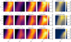 |
Fig. 7 Mutual information maps between |
![$\[A_{V}^{\text {tot }}\]$](/articles/aa/full_html/2024/11/aa51588-24/aa51588-24-eq123.png)
5.1 Best lines to infer AVtot for the reference use case
Figure 8 shows the mutual information between the visual extinction ![$\[A_{V}^{\text {tot }}\]$](/articles/aa/full_html/2024/11/aa51588-24/aa51588-24-eq130.png) and the intensity of either one line or a line couple, ranked by decreasing order of the mutual information. Only the first 15 most informative lines or couples are displayed for readability. Red error bars on the mutual information allow one to assess the significance of the line ranking (see Appendices C and E.2 for details on their computation).
and the intensity of either one line or a line couple, ranked by decreasing order of the mutual information. Only the first 15 most informative lines or couples are displayed for readability. Red error bars on the mutual information allow one to assess the significance of the line ranking (see Appendices C and E.2 for details on their computation).
In the case of the Horsehead Nebula featuring large variations of ![$\[A_{V}^{\text {tot }}\left(3 \leq A_{V}^{\text {tot }} \leq 24 ~\mathrm{mag})\right.\]$](/articles/aa/full_html/2024/11/aa51588-24/aa51588-24-eq131.png) , the most informative individual lines are the ground state transitions of 13CO, HCO+ and C18O, followed by the second transition of C18O and 13CO. The 12CO lines are individually poorly informative. These results are consistent with the mutual information maps from Fig. 6. The most informative couples of lines here simply combine the single most informative individual line – the ground state transition of 13CO – with another line. In particular, the most informative couple of lines (ground state transitions of 13CO and HCO+) combines the two most informative individual lines. However, this combination only improves the mutual information by about 0.2 bits. In other words, using only 13CO (1 − 0) to infer
, the most informative individual lines are the ground state transitions of 13CO, HCO+ and C18O, followed by the second transition of C18O and 13CO. The 12CO lines are individually poorly informative. These results are consistent with the mutual information maps from Fig. 6. The most informative couples of lines here simply combine the single most informative individual line – the ground state transition of 13CO – with another line. In particular, the most informative couple of lines (ground state transitions of 13CO and HCO+) combines the two most informative individual lines. However, this combination only improves the mutual information by about 0.2 bits. In other words, using only 13CO (1 − 0) to infer ![$\[A_{V}^{\text {tot }}\]$](/articles/aa/full_html/2024/11/aa51588-24/aa51588-24-eq132.png) instead of any line couple results in a limited loss of information.
instead of any line couple results in a limited loss of information.
Figures 8b, 8c and 8d show the line rankings for the three sub-regimes of ![$\[A_{V}^{\text {tot }}\]$](/articles/aa/full_html/2024/11/aa51588-24/aa51588-24-eq133.png) . In each of these sub-regimes, the ground state transition of 13CO is among the top two most informative individual lines, but it falls behind C18O for the highest
. In each of these sub-regimes, the ground state transition of 13CO is among the top two most informative individual lines, but it falls behind C18O for the highest ![$\[A_{V}^{\text {tot }}\]$](/articles/aa/full_html/2024/11/aa51588-24/aa51588-24-eq134.png) as it becomes optically thick. Conversely, the ground state transition of C18O improves its ranking as
as it becomes optically thick. Conversely, the ground state transition of C18O improves its ranking as ![$\[A_{V}^{\text {tot }}\]$](/articles/aa/full_html/2024/11/aa51588-24/aa51588-24-eq135.png) grows, because its S/N increases and it remains optically thin. In the translucent regime, one of the most informative couple of lines is (13CO (1 − 0), 12CO (1 − 0)), even though 12CO (1 − 0) is individually relatively uninformative in this regime. This can be explained by the fact that, for a single line, the excitation of the line shows a degeneracy between column density and gas temperature. A highly optically thick line, such as 12CO (1 − 0), provides information on the gas temperature, and thus helps lifting this degeneracy (Roueff et al. 2021, 2024).
grows, because its S/N increases and it remains optically thin. In the translucent regime, one of the most informative couple of lines is (13CO (1 − 0), 12CO (1 − 0)), even though 12CO (1 − 0) is individually relatively uninformative in this regime. This can be explained by the fact that, for a single line, the excitation of the line shows a degeneracy between column density and gas temperature. A highly optically thick line, such as 12CO (1 − 0), provides information on the gas temperature, and thus helps lifting this degeneracy (Roueff et al. 2021, 2024).
These results are consistent with Gratier et al. (2021). We both obtain that for the Horsehead Nebula, the three most informative line to trace the extinction include 13 CO (1 − 0) and HCO+ (1 − 0) for translucent gas. We also both find that they include the 13CO (1 − 0) and C18O (1 − 0) for filamentary gas.
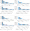 |
Fig. 8 Line selection for |
![$\[A_{V}^{\text {tot }}\]$](/articles/aa/full_html/2024/11/aa51588-24/aa51588-24-eq136.png)
![$\[A_{V}^{\text {tot }}\]$](/articles/aa/full_html/2024/11/aa51588-24/aa51588-24-eq137.png)
![$\[3 \leq A_{V}^{\text {tot }} \leq 24\]$](/articles/aa/full_html/2024/11/aa51588-24/aa51588-24-eq138.png)
![$\[3 \leq A_{V}^{\text {tot }} \leq 6\]$](/articles/aa/full_html/2024/11/aa51588-24/aa51588-24-eq139.png)
![$\[6 \leq A_{V}^{\text {tot }} \leq 12\]$](/articles/aa/full_html/2024/11/aa51588-24/aa51588-24-eq140.png)
![$\[12 \leq A_{V}^{\text {tot }} \leq 24\]$](/articles/aa/full_html/2024/11/aa51588-24/aa51588-24-eq141.png)
5.2 Best lines to infer G0 for the reference use case
Figure J.1 shows the mutual information between the incident UV radiative field intensity G0 and the intensity of individual or couples lines, sorted by decreasing mutual information. The mutual information with G0 is always lower than 0.65 bits.
The seven most informative lines are the [CII], [CI] and 12CO lines. While ![$\[A_{V}^{\text {tot }}\]$](/articles/aa/full_html/2024/11/aa51588-24/aa51588-24-eq142.png) is related to the cloud depth, G0 is a physical quantity defined at the cloud surface. It is therefore intuitive that the most informative lines for G0 are those that exist in the outer layers of the cloud. At the ionization front, the carbon is mostly in ionized state, and after the photodissociation front converts to C and then to mostly CO.
is related to the cloud depth, G0 is a physical quantity defined at the cloud surface. It is therefore intuitive that the most informative lines for G0 are those that exist in the outer layers of the cloud. At the ionization front, the carbon is mostly in ionized state, and after the photodissociation front converts to C and then to mostly CO.
When mixing all kinds of gas, the [CII] line is the most informative one. The mutual information of 12CO lines increases with the regime of ![$\[A_{V}^{\text {tot }}\]$](/articles/aa/full_html/2024/11/aa51588-24/aa51588-24-eq143.png) , and 12CO (1 − 0) becomes the most informative line to infer G0 toward dense cores. In this regime, the 12CO (1 − 0) line is optically thick. The intensity at which it saturates mostly depends on the kinetic temperature (Kaufman et al. 1999), and thus on G0. However, looking at pairs of lines, some combinations of molecular lines are more informative than any combination of the [CII] and [CI] lines. This result is encouraging for ISM studies since [CII] and [CI] lines can no longer be observed with Herschel and SOFIA. In particular, to the best of our knowledge, there is currently no instrument that can observe the [CII] line, and this should not change in the coming years.
, and 12CO (1 − 0) becomes the most informative line to infer G0 toward dense cores. In this regime, the 12CO (1 − 0) line is optically thick. The intensity at which it saturates mostly depends on the kinetic temperature (Kaufman et al. 1999), and thus on G0. However, looking at pairs of lines, some combinations of molecular lines are more informative than any combination of the [CII] and [CI] lines. This result is encouraging for ISM studies since [CII] and [CI] lines can no longer be observed with Herschel and SOFIA. In particular, to the best of our knowledge, there is currently no instrument that can observe the [CII] line, and this should not change in the coming years.
5.3 Effect of integration time on the best lines to infer Avtot
We here check the impact of a ten-fold increase in the integration time (deeper integration use case) on the line ranking. For concision, only the results for ![$\[A_{V}^{\text {tot }}\]$](/articles/aa/full_html/2024/11/aa51588-24/aa51588-24-eq144.png) are analyzed.
are analyzed.
Figure J.2 compares the mutual information between the line intensities and ![$\[A_{V}^{\text {tot }}\]$](/articles/aa/full_html/2024/11/aa51588-24/aa51588-24-eq145.png) for the reference and the deeper integration use case. As was expected, the mutual information increases or saturates with the integration time. Saturation is almost reached for the 13CO, HCO+, and 12CS lines, when they are considered alone. In contrast, this increase is larger for combinations of two lines than for individual lines. Moreover, the mutual information increase varies as a function of the line or couple of lines.
for the reference and the deeper integration use case. As was expected, the mutual information increases or saturates with the integration time. Saturation is almost reached for the 13CO, HCO+, and 12CS lines, when they are considered alone. In contrast, this increase is larger for combinations of two lines than for individual lines. Moreover, the mutual information increase varies as a function of the line or couple of lines.
For individual lines, the S/N improvement mostly benefits the ground state transition of C18O, HNC, HCN, as well as HCO+ (2 − 1), with an approximate 0.5 bits increase in mutual information. These lines all have a median S/N of about 1 in the reference case, as is shown in Fig. 3. Improving the S/N thus has a strong impact on their informativity. Conversely, the ground state transition of 13CO, HCO+, and 12CO, along with 12CS (2 − 1), only have an improvement of about 0.1 bits. These lines all have a median S/N of at least 10 in the reference case. Despite these differences, the three overall most informative individual lines remain the ground state transition of 13CO, HCO+ and C18O. At higher S/Ns, some higher energy transitions, such as those of HCO+ and 12CS, provide more information than the lowest one. This justifies the use of the 2 mm and 1 mm atmospheric bands.
For couples of lines, the top three most informative couples remain identical in all regimes, except in dense cores where the ranking completely changes. Indeed, combinations involving HCN (1 − 0) or HNC (1 − 0) and HCO+ (1 − 0), or the (hCN(1 − 0), 12CS(5 − 4)) couple, gain more than 0.7 bits of mutual information and become some of the most informative couples. This can be explained by the fact that 1) HNC and HCN become more abundant in dense cores, 2) these lines have large values of critical densities (higher than 106 cm−3, see Tielens 2005, Table 2.4), and 3) the significant increase in integration time enables these lines to become informative. Significantly increasing the integration time, and therefore the S/N, is thus useful to increase the informative potential of lines, even though they were already detected in the reference case.
5.4 Effect of uncertain geometry on the best lines to infer G0
The geometry in ISM clouds is uncertain. The impact of this uncertainty is more important for physical parameters defined at the surface of the cloud, such as G0, than for quantities integrated along the line of sight, such as the visual extinction. We thus only consider the effect of the uncertain geometry in inferring G0. We simply use a scaling factor (see Eq. (17)) to take into account the uncertainty about the geometry, such as beam dilution effect and cloud surface orientation. As a reminder, log10 κ is assumed to be uniformly distributed between −0.5 and 0.5.
Figure J.3 compares the mutual information between the line intensities and G0 for the reference case and in this uncertain geometry use case. It shows that the best tracers of G0 remain surface tracers in all ![$\[A_{V}^{\text {tot }}\]$](/articles/aa/full_html/2024/11/aa51588-24/aa51588-24-eq146.png) regimes; that is, the [CII] line or the combination of the [CII] and [CI] lines. We note that for translucent gas, the combination of the 12CO and 13CO molecular lines is formally ranked before the [CII] and [CI] lines. However, this ranking might be due to estimation error, as the error bars are larger than the difference of estimated mutual information. Overall, while nonzero, the mutual information with G0 is low; that is, a precise estimation of G0 is difficult. It thus is all the more important to select the best tracers. In addition, couples of lines bring significantly higher information on G0 than single lines.
regimes; that is, the [CII] line or the combination of the [CII] and [CI] lines. We note that for translucent gas, the combination of the 12CO and 13CO molecular lines is formally ranked before the [CII] and [CI] lines. However, this ranking might be due to estimation error, as the error bars are larger than the difference of estimated mutual information. Overall, while nonzero, the mutual information with G0 is low; that is, a precise estimation of G0 is difficult. It thus is all the more important to select the best tracers. In addition, couples of lines bring significantly higher information on G0 than single lines.
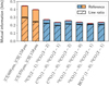 |
Fig. 9 Comparison between the amount of information on G0 provided by the five best couples of lines in Fig. J.3 (colored bars) and their line ratio (hatched bars). |
5.5 Using line ratios leads to a loss of information
Using line intensity ratios in the analysis of spectral data of interstellar clouds is common in ISM studies to eliminate observational uncertainties such as the dependency with the cloud geometry (see, e.g., Cormier et al. 2015; Kaplan et al. 2021). Assuming that the geometry effects impact the line intensities in similar ways, this allows observers to get rid of the scaling factor, κ, from Eq. (17) for a high enough S/N. Besides, as line ratios reduce the dimensionality from two or more to one, they allow for simpler visualizations and thus a simpler understanding of ISM properties (Kaufman et al. 1999). Similarly to line selection, assessing the relevance of a large set of line ratios to select the best ones was already done before. For instance, Bron et al. (2021) uses random forests to select the line ratio that best traces the ionization fraction. As was mentioned in Sect. 2.1, the line selection method presented in Sect. 2.7 can be applied with line ratios. This section illustrates an important specificity of line ratios to have in mind when evaluating their physical relevance.
Figure 9 compares the mutual information between G0 and either a couple of lines or their line ratios. We perform this comparison for the five most informative line couples for filamentary gas ![$\[\left(6 \leq A_{V}^{\text {tot }} \leq 12\right)\]$](/articles/aa/full_html/2024/11/aa51588-24/aa51588-24-eq147.png) and with a random scaling factor, κ. In all cases, the mutual information with the line couple is larger than with the line ratio. This can be explained theoretically. Computing a line ratio goes from two dimensions or more (the integrated intensities of the two or more lines) to only one (the ratio) and is thus not a bijective operation. As is stated in Sect. 2.6, a non-bijective transformation results in a loss of information. However, this loss of information differs from one line couple to another. On the figure, two classes of line combinations appear.
and with a random scaling factor, κ. In all cases, the mutual information with the line couple is larger than with the line ratio. This can be explained theoretically. Computing a line ratio goes from two dimensions or more (the integrated intensities of the two or more lines) to only one (the ratio) and is thus not a bijective operation. As is stated in Sect. 2.6, a non-bijective transformation results in a loss of information. However, this loss of information differs from one line couple to another. On the figure, two classes of line combinations appear.
For couples of [CI] and [CII] lines, the joint analysis yields much larger mutual information values than analyzing the associated line ratio; that is, using a line intensity ratio instead of the two lines intensities results in a large loss of information. The [CII] line being a cooling line emitted from the cloud surface, its intensity contains a lot of information on G0, which is partially lost when using a ratio. For molecular line combinations, here combining a low-J 12CO line and another millimeter line, this loss of information is much smaller, almost negligible. In this specific example, studying how G0 depends on a line ratio instead of the original line couple is both simpler and equivalent in terms of informativity.
More generally, line ratios can be valuable tools to inspect ISM properties. For a given set of lines, noise characteristics and physical regime, mutual information can permit observers to identify lines ratios that are most informative on a physical parameter or combination of physical parameters. However, working with line ratios instead of the original set of lines can lead to a significant loss of information. Therefore, for tasks that seek to exploit as much information as possible from a costly dataset such as inference, considering the original set of lines should be more relevant than line ratios.
6 Conclusion
In this work, we showed how information theory concepts such as mutual information (Cover & Thomas 2006, Sect. 8.6) can be used to evaluate quantitatively capability of line observations to constrain physical parameters such the visual extinction ![$\[A_{V}^{\text {tot }}\]$](/articles/aa/full_html/2024/11/aa51588-24/aa51588-24-eq148.png) or the UV radiative field G0. Such a quantitative criterion opens a new perspective to visualize and understand the statistical relationships between physical parameters and tracers. In particular, mutual information relies on few and nonrestrictive assumptions on the considered probability distributions. Therefore, conclusions drawn from it only depend on the underlying physics and the noise properties of the observations. In addition, mutual information can also be used to determine the best lines to observe in a future observation campaign given an instrument specifications, and to recommend a target integration time. To illustrate the potential of the proposed method, we applied it to lines observable with the EMIR instrument at the IRAM 30m radio telescope for physical regimes similar to those found in the Horsehead Nebula. The results for this case are as follows.
or the UV radiative field G0. Such a quantitative criterion opens a new perspective to visualize and understand the statistical relationships between physical parameters and tracers. In particular, mutual information relies on few and nonrestrictive assumptions on the considered probability distributions. Therefore, conclusions drawn from it only depend on the underlying physics and the noise properties of the observations. In addition, mutual information can also be used to determine the best lines to observe in a future observation campaign given an instrument specifications, and to recommend a target integration time. To illustrate the potential of the proposed method, we applied it to lines observable with the EMIR instrument at the IRAM 30m radio telescope for physical regimes similar to those found in the Horsehead Nebula. The results for this case are as follows.
The determination of the optimal combination of lines to estimate a physical parameter depends heavily on the achieved S/N and thus on the integration time for single-dish telescopes. For instance, the HCN and HNC (1 − 0) lines achieve their full potential as dense cores tracers only for a S/N ≳ 20;
The line intensity has to vary significantly as a function of the physical parameters to get a high precision during the inference. This implies that the capability of a line to infer a physical parameter such as the visual extinction depends on the physical regime. For instance, the best lines in the Horsehead Nebula – for an integration time similar to that of the ORION-B Large Program – are 13CO and HCO+ (1 − 0) for translucent gas (
![$\[\left(3 \leq A_{V}^{\text {tot }} \leq 6,{ }^{13} \mathrm{CO}, \mathrm{HCO}^{+}\right.\]$](/articles/aa/full_html/2024/11/aa51588-24/aa51588-24-eq149.png) and C18O (1 − 0) for filamentary gas (
and C18O (1 − 0) for filamentary gas (![$\[\left(6 \leq A_{V}^{\text {tot }} \leq 12\right.\]$](/articles/aa/full_html/2024/11/aa51588-24/aa51588-24-eq150.png) , and 13CO and C18O (1 − 0) for dense cores
, and 13CO and C18O (1 − 0) for dense cores ![$\[\left(12 \leq A_{V}^{\text {tot }} \leq 24\right)\]$](/articles/aa/full_html/2024/11/aa51588-24/aa51588-24-eq151.png) ;
;The low-J lines of the CO isotopologues are key tracers of the gas column density for a wide range of the
![$\[\left(A_{V}^{\text {tot }}, G_{0}\right)\]$](/articles/aa/full_html/2024/11/aa51588-24/aa51588-24-eq152.png) space;
space;Surface tracers such as the [CII] line, the [CI] lines, or 12CO lines are the most useful tracers of G0. However, G0 is much more difficult to estimate than
![$\[A_{V}^{\text {tot }}\]$](/articles/aa/full_html/2024/11/aa51588-24/aa51588-24-eq153.png) ;
;The best combination does not always combine the best individual lines. Considering the combination of the K ≥ 2 best individual lines as the best subset of K lines may thus lead to a suboptimal choice.
The proposed methods are general enough to be applicable to any ISM model or even observational dataset. The latter application will be the subject of the second paper in this set. The Python software that implements the general method we proposed is available in open access9. The simulator of line observations based on Meudon PDR code predictions is also available10. It allows us to simulate observations from the EMIR receiver at the IRAM 30m radio telescope, but can be adapted to any other instruments (including those operating in other frequency ranges). In this case, the user would only need to specify the noise and calibration properties. Finally, the scripts that reproduce the exact results presented in this paper are available in another repository11.
To simplify the presentation and interpretations, this work focused on constraining physical parameters individually. For an observation campaign, the lines to be observed will be used to constrain multiple physical parameters – such as visual extinction ![$\[A_{V}^{\text {tot }}\]$](/articles/aa/full_html/2024/11/aa51588-24/aa51588-24-eq154.png) and the intensity of the UV radiative field G0 at once. In this case, mutual information should be used to search for the line combinations that best constrain the combination of these physical parameters. In particular, this method has the potential to indicate that combinations of physical parameters may be constrained by a given set of lines, even though each individual parameter is not constrained by the same set of lines.
and the intensity of the UV radiative field G0 at once. In this case, mutual information should be used to search for the line combinations that best constrain the combination of these physical parameters. In particular, this method has the potential to indicate that combinations of physical parameters may be constrained by a given set of lines, even though each individual parameter is not constrained by the same set of lines.
Finally, this work focused line integrated intensities as these are the quantities predicted by the considered ISM model, the Meudon PDR code. However, the proposed approach could be applied with any observable. For instance, radio telescopes yield full line profiles. Since integrating these line profiles is a nonbijective transformation, considering the integrated intensity instead of the line profile results in a loss of information. Future work could quantify this loss exploiting mutual information.
Acknowledgements
This work received support from the French Agence Nationale de la Recherche through the DAOISM grant ANR-21-CE31-0010, and from the Programme National “Physique et Chimie du Milieu Interstellaire” (PCMI) of CNRS/INSU with INC/INP, co-funded by CEA and CNES. It also received support through the ANR grant “MIAI @ Grenoble Alpes” ANR-19-P3IA-0003. This work was partly supported by the CNRS through 80Prime project OrionStat, a MITI interdisciplinary program, by the ANR project “Chaire IA Sherlock” ANR-20-CHIA-0031-01 held by P. Chainais, and by the national support within the programme d’investissements d’avenir ANR-16-IDEX-0004 ULNE and Région HDF. JRG and MGSM thank the Spanish MCINN for funding support under grant PID2019-106110G-100. MSGM acknowledges support from the NSF under grant CAREER 2142300. Part of the research was carried out at the Jet Propulsion Laboratory, California Institute of Technology, under a contract with the National Aeronautics and Space Administration (80NM0018D0004). D.C.L. acknowledges financial support from the National Aeronautics and Space Administration (NASA) Astrophysics Data Analysis Program (ADAP). Finally, we thank Tommaso Grassi for his constructive comments and feedback that helped us improve this article.
Appendix A Details on the two-dimensional illustrative example
Section 2.2 introduces a joint distribution on (Θ, Y) that follows a two-dimensional lognormal distribution. Its parameters, μ and ∑, correspond to the mean vector and covariance matrix in the logarithmic scale, respectively. They are set to obtain expectations of 1, a standard deviation such that a 1σ error corresponds to a factor of 1.3, and a ρ = 0.9 correlation coefficient in linear scale. One can show that the associated distribution parameters are
![$\[\begin{aligned}\boldsymbol{\mu} & =-\frac{1}{2}\binom{(\ln 1.3)^2}{(\ln 1.3)^2} \simeq\binom{-0.0344}{-0.0344} \text { and } \\\boldsymbol{\Sigma} & =\left(\begin{array}{lr}(\ln 1.3)^2 \qquad \ln \left[1+0.9\left(e^{(\ln 1.3)^2}-1\right)\right] \\\ln \left[1+0.9\left(e^{(\ln 1.3)^2}-1\right)\right] \qquad (\ln 1.3)^2\end{array}\right) \simeq\left(\begin{array}{ll}0.0688 & 0.0622 \\0.0622 & 0.0688\end{array}\right).\end{aligned}\]$](/articles/aa/full_html/2024/11/aa51588-24/aa51588-24-eq155.png) (A.1)
(A.1)
In this simple case, one can show that Θ | Y ~ log 𝒩(μ, σ2) with
![$\[\left\{\begin{array}{l}\mu=-\frac{1}{2} \boldsymbol{\Sigma}_{1,1}+\frac{\boldsymbol{\Sigma}_{1,2}}{\boldsymbol{\Sigma}_{1,1}}\left(\ln y+\frac{1}{2} \boldsymbol{\Sigma}_{1,1}\right) \\\boldsymbol{\Sigma}^2=\boldsymbol{\Sigma}_{1,1}-\frac{\boldsymbol{\Sigma}_{1,2}^2}{\boldsymbol{\Sigma}_{1,1}}\end{array}\right.\]$](/articles/aa/full_html/2024/11/aa51588-24/aa51588-24-eq156.png) (A.2)
(A.2)
Appendix B What is a bit of information?
Figure B.1 illustrates six probability distributions on a fictitious two-dimensional physical parameter: four uniform distributions on compact sets and two Gaussian distributions. The two compact sets on the top left have the same area, denoted c. By construction, the three distributions on the left share the same differential entropy, namely h (Θ) = log2 c bits. For the two-dimensional normal distribution,
![$\[h(\Theta)=\log _2\left[2 \pi e \sigma^2\right]+\frac{1}{2} \log _2\left(1-\rho^2\right) \quad \text { for } \Sigma=\left(\begin{array}{cc}\sigma^2 & \rho \sigma^2 \\\rho \sigma^2 & \sigma^2\end{array}\right).\]$](/articles/aa/full_html/2024/11/aa51588-24/aa51588-24-eq157.png)
Using σ2 = c/(2πe), the first term in the sum simplifies to log2 c bits. The correlation coefficient is ρ2 = 0, so that ![$\[\frac{1}{2} ~\log _{2}\left(1-\rho^{2}\right)=0\]$](/articles/aa/full_html/2024/11/aa51588-24/aa51588-24-eq158.png) bit and h (Θ) = log2 c bits. The three distributions on the right are transformed versions of the left column. Each transformation results in a decrease in the entropy of 1 bit. Indeed, the two compact sets on the top right have a c/2 area and the entropy of the associated uniform distributions is thus h (Θ) = log2(c/2) = log2 c − 1 bits. For the two-dimensional Gaussian, the correlation coefficient is ρ2 = 3/4 in the right column, leading to
bit and h (Θ) = log2 c bits. The three distributions on the right are transformed versions of the left column. Each transformation results in a decrease in the entropy of 1 bit. Indeed, the two compact sets on the top right have a c/2 area and the entropy of the associated uniform distributions is thus h (Θ) = log2(c/2) = log2 c − 1 bits. For the two-dimensional Gaussian, the correlation coefficient is ρ2 = 3/4 in the right column, leading to ![$\[\frac{1}{2} \log _{2}\left(1-\rho^{2}\right)=-1\]$](/articles/aa/full_html/2024/11/aa51588-24/aa51588-24-eq159.png) bit. It should be noted that the use of the binary base to express values in bits provides a simple interpretation when comparing entropy values: a difference of 1 bit of information corresponds to a factor of two of standard deviation. Therefore, in an estimation procedure, decreasing the entropy by 1 bit results in improving the precision by a factor of two.
bit. It should be noted that the use of the binary base to express values in bits provides a simple interpretation when comparing entropy values: a difference of 1 bit of information corresponds to a factor of two of standard deviation. Therefore, in an estimation procedure, decreasing the entropy by 1 bit results in improving the precision by a factor of two.
Appendix C Estimating the mutual information
Several Monte Carlo estimators ![$\[\widehat{I}_{N}\left(\Theta, Y^{(s)}\right)\]$](/articles/aa/full_html/2024/11/aa51588-24/aa51588-24-eq160.png) of mutual information exist – see Walters-Williams & Li (2009) for a review. In this section, we compare two such estimators: the nonparametric “Kraskov estimator” (Kraskov et al. 2004) (used in this work), and an estimator based on the assumption that the joint PDF of (Θ, Y(s)) is Gaussian.
of mutual information exist – see Walters-Williams & Li (2009) for a review. In this section, we compare two such estimators: the nonparametric “Kraskov estimator” (Kraskov et al. 2004) (used in this work), and an estimator based on the assumption that the joint PDF of (Θ, Y(s)) is Gaussian.
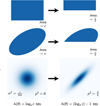 |
Fig. B.1 Entropy definition illustration for different example distributions on θ. The first two rows show the PDF of uniform distributions on different sets, and the last row of Gaussian distributions. The distributions in one column have an equal differential entropy h (Θ) whose value depends on a positive constant c. Each arrow indicates a gain of 1 bit of information, i.e., a decrease in the entropy of 1 bit. In the last row, the variance in both horizontal and vertical directions is denoted σ2, and the correlation coefficient ρ. |
The Kraskov estimator is based on nearest neighbors (NN) – see Appendix D for more details on this approach. It is notably used by the SCIPY Python package12. It does not make assumptions on the shape of the joint distribution on (Θ, Y(s)). It can thus capture both linear and nonlinear relationships between lines Y(s) and physical parameters Θ. It is asymptotically unbiased; that is, it converges to the exact mutual information in the large number of observations limit N → ∞. To reduce the bias that can occur at small N, we apply the Gaussian reparametrization strategy from Holmes & Nemenman (2019), which bijectively transforms each marginal distribution to a Gaussian. Appendix E.1 provides more details on this bias reduction technique.
Under the assumption that the joint PDF of (Θ, Y(s)) is Gaussian, the mutual information is simply a function of the canonical correlations (CC, Schreier 2008). Since canonical correlation can be estimated based on second order empirical moment, our second mutual information estimator is obtained by injecting the estimated canonical correlation coefficient in the analytical entropy formula for a Gaussian distribution after application of the Gaussian reparametrization strategy (Holmes & Nemenman 2019). The “CC estimator” has shorter computation time than the Kraskov estimator, because it only requires evaluations of second order moments. However, as imposing the Gaussianity of marginal is generally not sufficient to match the multivariate Gaussian assumption, the “CC estimator” is only asymptotically unbiased in the general case. Appendix F provides more details on this estimator.
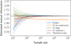 |
Fig. C.1 Comparison of four mutual information estimators applied on the simple lognormal bivariate distribution presented in Sect. 2.1. The dashed black line corresponds to the theoretical value. The 1σ interval is not shown for the simple canonical correlation-based estimator as it appears to be asymptotically biased. The Kraskov estimator (in blue) converges to the correct value for a large number of simulated observations N. The CC estimator is used with three preprocessing: no preprocessing, log and Gaussian reparametrization. As the joint distribution is non-Gaussian, the no-preprocessing case does not converge to the theoretical value. However, the other two preprocessing transform it to a Gaussian, the associated CC estimators converge to the theoretical value for large values of N. |
For both estimators, the variance evolution with different sample sizes N allows us to assess their accuracy and to estimate error bars. To do this, we follow a method introduced in Holmes & Nemenman (2019), and summarized in Appendix E.2.
Figure C.1 quantitatively shows the behavior of both estimators as a function of the number of N for the bivariate lognormal case introduced in Sect. 2.2. The Kraskov estimator is biased for a low number of observations N but is very close to the theoretical value for N ≥ 103. The canonical estimator is combined with three different transformations of the marginal distributions of Y(s) and Θ: 1) no preprocessing, 2) taking the logarithm of the random variables, and 3) the Gaussian reparametrization described above. In the no preprocessing case, the CC estimator does not converge to the true value, because the samples are log-normally distributed instead of being normally distributed as required by the estimator. For instance, for N = 103, the mean error on the estimation in the no preprocessing case is about twice its standard deviation, while it is 3 and 5 times lower than its standard deviation for the Kraskov estimator, and the CC estimator with Gaussian reparameterization, respectively.
Astrophysical models produce complex and nonlinear relationships between lines Y(s) and physical parameters Θ. The previous discussion shows that the canonical estimator is potentially useful when the sample size is small. Applying a marginal Gaussian reparametrization is a simple solution to reduce the bias, even though this transformation does not always yield normal joint distributions on (Θ, Y(s)). Using this strategy, the Kraskov estimator seems to give adequate results for N ≥ 104, and does not require any Gaussianity assumption.
In the remainder of this work, we use the Kraskov estimator to evaluate the mutual information. This estimator is evaluated with the NPEET Python package13. This package handles many-to-many relationships; that is, it permits the evaluation of the mutual information between combinations of lines and combinations of physical parameters. Conversely, as of today, the more common implementation from SCIPY only handles one-to-one relationships.
Appendix D Nearest neighbors-based estimators
D.1 Naive estimation of entropy
Calculating entropy involves estimating the variable’s PDF. Traditionally, this is done using a histogram (Beirlant et al. 1997). However, this approach creates widely skewed probability densities, leading to biases in the entropy estimator. Moreover, this approach suffers in high dimensions (Miller 1955), due to the so-called curse of dimensionality (Kouiroukidis & Evangelidis 2011).
A popular alternative is to estimate the PDF using the nearest neighbors method (Beirlant et al. 1997). Indeed, intuitively, if the k-th nearest neighbor of a point is close to it, then the PDF of the random variable in its neighborhood is high (see Fig. D.1). The PDF of the variable X in the neighborhood of Xi is then approximated by the expression
![$\[\widehat{\pi}_X\left(x_i\right)=\frac{k / N}{\mathcal{V}_d\left(\epsilon_k^{(i)}\right)}\]$](/articles/aa/full_html/2024/11/aa51588-24/aa51588-24-eq161.png) (D.1)
(D.1)
where N is the total number of samples, ![$\[\epsilon_{k}^{(i)}\]$](/articles/aa/full_html/2024/11/aa51588-24/aa51588-24-eq162.png) the distance from xi to its k-th nearest neighbor and
the distance from xi to its k-th nearest neighbor and ![$\[\mathcal{V}_{d}(r)\]$](/articles/aa/full_html/2024/11/aa51588-24/aa51588-24-eq163.png) the volume of a ball of radius r in ℝd. This then allows the entropy to be estimated by the following Monte Carlo estimator,
the volume of a ball of radius r in ℝd. This then allows the entropy to be estimated by the following Monte Carlo estimator,
![$\[\widehat{h}(X)=-\frac{1}{N} \sum_{i=1}^N \log \widehat{\pi}_X\left(x_i\right).\]$](/articles/aa/full_html/2024/11/aa51588-24/aa51588-24-eq164.png) (D.2)
(D.2)
Combining equations 1 and 2, and using the fact that the volume of a d-ball of radius r is ![$\[\mathcal{V}_{d}(r)=r^{d} ~V_{d}\]$](/articles/aa/full_html/2024/11/aa51588-24/aa51588-24-eq165.png) , where Vd is the volume of the unit d-ball; that is, the d-ball of radius 1, we obtain the following expression of the estimator,
, where Vd is the volume of the unit d-ball; that is, the d-ball of radius 1, we obtain the following expression of the estimator,
![$\[\widehat{h}(X)=\log N-\log k+\log V_d+\frac{d}{N} \sum_{i=1}^N \log \epsilon_k^{(i)}.\]$](/articles/aa/full_html/2024/11/aa51588-24/aa51588-24-eq166.png) (D.3)
(D.3)
D.2 Kozachenko-Leonenko estimator of entropy
The previous estimator is prone to high bias, especially when the number of neighbors k or the number of samples N are small. To address this issue, Kozachenko & Leonenko (1987) proposed the following estimator,
![$\[h_{\mathrm{KL}}(X)=\psi(N)-\psi(k)+\log V_d+\frac{d}{N} \sum_{i=1}^N \log \epsilon_k^{(i)},\]$](/articles/aa/full_html/2024/11/aa51588-24/aa51588-24-eq167.png) (D.4)
(D.4)
where ψ is the digamma function. The digamma function behaves similarly to the logarithm for high values. On the other hand, it differs for small values (see Fig. D.2).
The digamma function acts as a correction term and ensures that this estimator remains asymptotically unbiased, which is only the case for the naive one if k and N are high. More details about how the digamma function appears in the Kozachenko-Leonenko estimator are provided in Kraskov et al. (2004).
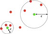 |
Fig. D.1 Illustration of the k-NN estimators for k = 3. For each green point, the distance to its third nearest neighbor, denoted εd, is represented. A low distance implies a locally high density. |
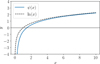 |
Fig. D.2 Graph of the digamma function ψ on |
![$\[\mathbb{R}_{+}^{*}\]$](/articles/aa/full_html/2024/11/aa51588-24/aa51588-24-eq168.png)
D.3 Kraskov estimator of mutual information
A naive mutual information estimator could be based directly on the Kozachenko-Leonenko estimator from the relationship I (X, Y) = h (X) + h (Y) − h (X, Y). Kraskov et al. (2004) argued that this solution would be highly biased. Instead, they proposed the following estimator,
![$\[I_{\mathrm{KSG}}(X, Y)=\psi(k)-1 / k-\left\langle\psi\left(n_x(k)\right)+\psi\left(n_y(k)\right)\right\rangle+\psi(N),\]$](/articles/aa/full_html/2024/11/aa51588-24/aa51588-24-eq169.png) (D.5)
(D.5)
where nx(k) is the number of points j such that ![$\[\left\|x_{j}-x_{i}\right\| \leq \epsilon_{x}^{(i)} / 2\]$](/articles/aa/full_html/2024/11/aa51588-24/aa51588-24-eq170.png) ,
, ![$\[n_{y}(k)\]$](/articles/aa/full_html/2024/11/aa51588-24/aa51588-24-eq171.png) is the number of points j such that
is the number of points j such that ![$\[\left\|y_{j}-y_{i}\right\| \leq \epsilon_{y}^{(i)} / 2\]$](/articles/aa/full_html/2024/11/aa51588-24/aa51588-24-eq172.png) and ⟨·⟩ denotes the average value over all points i. This approach to calculating mutual information is illustrated in Fig. D.3.
and ⟨·⟩ denotes the average value over all points i. This approach to calculating mutual information is illustrated in Fig. D.3.
Nearest neighbors entropy estimates, and in a lower extent Kraskov’s estimate of mutual information, are sensitive to duplicates in the data. In fact, it means that ![$\[\epsilon_{k}^{(i)}=0\]$](/articles/aa/full_html/2024/11/aa51588-24/aa51588-24-eq173.png) for at least one i, which leads to an infinitely negative entropy. This result is not absurd: it is the theoretical value we would expect to obtain for a distribution containing one or more diracs. If duplicates are not handled properly, for example by adding noise or reparameterizing, they can lead to a significant bias in estimates.
for at least one i, which leads to an infinitely negative entropy. This result is not absurd: it is the theoretical value we would expect to obtain for a distribution containing one or more diracs. If duplicates are not handled properly, for example by adding noise or reparameterizing, they can lead to a significant bias in estimates.
Appendix E Bias and variance of the estimator
E.1 Bias of the estimator
The bias of an estimator quantifies the systematic error in the estimation, which is the difference between the true value and the average estimated value over many datasets drawn from the same distribution. Kraskov et al. (2004) identify that non-skewed distribution, in particular Gaussian distribution, led to a lower bias and suggests that reparameterizing the marginal distributions into Gaussians could be a way of controlling the bias. Holmes & Nemenman (2019) proposed the following formula to transform any univariate distribution into a Gaussian one
![$\[x_i^{\prime}=\sqrt{2} \operatorname{erf}^{-1}\left(\frac{2 r_i-1}{N}-1\right).\]$](/articles/aa/full_html/2024/11/aa51588-24/aa51588-24-eq174.png) (E.1)
(E.1)
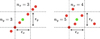 |
Fig. D.3 Illustration of the k-NN estimator of mutual information for k = 3. In the first panel, the mutual information is high so nx and ny are close to k. In the second panel, the mutual information is low so nx and ny are much higher than k. |
where 1 ≤ ri ≤ N is the rank of the sample xi in a sorted array (regardless of whether it is in ascending or descending order). This formula consists of two parts. First, the ![$\[\frac{2 r_{i}-1}{N}\]$](/articles/aa/full_html/2024/11/aa51588-24/aa51588-24-eq175.png) transformation is used to transform any distribution into a uniform distribution over the [0, 1] segment. Secondly, the Gaussian cumulative distribution function (CDF) Φ,
transformation is used to transform any distribution into a uniform distribution over the [0, 1] segment. Secondly, the Gaussian cumulative distribution function (CDF) Φ,
![$\[\Phi(x)=\frac{1}{2}\left[1+\operatorname{erf}^{-1}\left(\frac{x}{\sqrt{2}}\right)\right],\]$](/articles/aa/full_html/2024/11/aa51588-24/aa51588-24-eq176.png) (E.2)
(E.2)
is used to transform the uniform distribution into a reduced-centered normal distribution. It should be noted that, by changing the CDF Φ, we could reparametrize the data in any distribution which has an analytic CDF. We emphasize that even though this reparametrization transforms all the marginal distributions to Gaussians, the obtained joint distribution is not a multivariate normal in general.
It appears that the bias becomes substantial when calculating the mutual information between several lines and physical parameters. The intuitive reason is that it then becomes more difficult to identify the statistical relationships, which can be arbitrarily complex. If the number of observations is small, these can be missed, resulting in a significant underestimation of the mutual information.
E.2 Variance of the estimator
The variance of an estimator quantifies the dispersion of estimations for different numbers of samples from the same population. Knowing this dispersion is important in determining how reliable a single estimate is. However, the variance of the nonparametric mutual information estimator does not have a closed-form formula. Usually, this problem is solved by bootstrapping, which is a method of resampling with replacement (Johnson 2001). However, this is not possible here because the estimate is not linear in the probability distribution (e.g., duplicate data does not count twice). As was proposed by Holmes & Nemenman (2019), estimating the variance of the Kraskov estimator can be achieved by considering that the variance is inversely proportional to the sample size. This is a property shared by many estimators, such as the mean estimator. In the case of the Kraskov estimator, the variance can then be expressed as
![$\[\operatorname{Var}\left(\widehat{I_N}\right)=\frac{B}{N},\]$](/articles/aa/full_html/2024/11/aa51588-24/aa51588-24-eq177.png) (E.3)
(E.3)
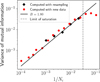 |
Fig. E.1 Comparison between the estimation of variances for different numbers of samples for a bivariate normal distribution with ρ = 0.8. Red markers: variances estimated with several different datasets. Black markers: variances estimated with subsampling of a single dataset. Black line: regression line to predict the variance for any number of samples. The limit of saturation indicated by a dashed line corresponds to the number of samples for which the relationship of Eq. E.3 no longer holds. |
where B is a model fitting parameter to the empirical variances that remains to be estimated and depends on the data distribution.
To estimate the value of B, we calculate the variance for different numbers of samples. To do this, we separate the data into several subsets of equal size. For example, for a total number of 1000 samples, it is possible to create 10 subsets of 100 samples, or 20 subsets of 50 samples. Once the variance is computed for several numbers of samples, the B value can be estimated by fitting a line curve. More precisely, Holmes & Nemenman (2019) proposed to estimate B as
![$\[\widehat{B}=\frac{N \sum_i \frac{n_i-1}{n_i} \widehat{\sigma}^2\left(N_i\right)}{\sum_i n_i-1}.\]$](/articles/aa/full_html/2024/11/aa51588-24/aa51588-24-eq178.png) (E.4)
(E.4)
This method is illustrated in Fig. E.1. Empirically, the value of B is usually between 1 and 3.
Appendix F Canonical correlations-based estimation of mutual information
Under the assumption that the joint distribution of observations and parameters (X, θ) is a multivariate normal distribution, the mutual information between observations and parameters can be expressed as follows
![$\[I^{\mathrm{CC}}=-\frac{1}{2} \sum_i \log \left(1-\lambda_i^2\right)\]$](/articles/aa/full_html/2024/11/aa51588-24/aa51588-24-eq179.png) (F.1)
(F.1)
where the {λi}i are called the canonical correlations of (X, θ). They satisfy the constraint ∀i, 0 ≤ λi ≤ 1 and are the singular values of the normalized correlation matrix MXθ defined as
![$\[M_{X \theta}=C_{X X}^{-\frac{1}{2}} C_{X \theta} C_{\theta \theta}^{-\frac{1}{2}}\]$](/articles/aa/full_html/2024/11/aa51588-24/aa51588-24-eq180.png) (F.2)
(F.2)
where C denotes the empirical correlation matrix and ![$\[C^{-\frac{1}{2}}\]$](/articles/aa/full_html/2024/11/aa51588-24/aa51588-24-eq181.png) the inverse of the matrix square root. These coefficients are the basis of the method known as “canonical correlation analysis.” Notably, the coefficient λ1 can be interpreted as the highest possible correlation coefficient between any linear combination of observables and any linear combination of lines.
the inverse of the matrix square root. These coefficients are the basis of the method known as “canonical correlation analysis.” Notably, the coefficient λ1 can be interpreted as the highest possible correlation coefficient between any linear combination of observables and any linear combination of lines.
Compared with the Kraskov estimator, the estimator in Eq. F.1 is much faster to compute. However, when the joint distribution is different from a multivariate normal distribution, the mutual information estimate may be asymptotically biased. A critical case occurs when the data are decorrelated yet statistically dependent (e.g., θ = X2 + ε). The correlation coefficient is then zero, resulting in a zero CC estimate of the mutual information while in the limit ε → 0 the analytical mutual information tends toward infinity.
Appendix G Considered lines
In this section, we describe in more detail the 36 lines retained in Sect. 3.3. They are used for mutual information maps (Sect. 4.2) and line selection (Sect. 5). Table G.1 gathers the additive and multiplicative noise levels for each of the 33 millimeter lines, and provides the fraction of the full parameter space for which the S/N is greater than 3. The millimeter lines selected are those for which this fraction is greater than 1%. Table G.2 gathers the same information for the three [CI] and [CII] lines.
Figure G.1 displays the considered lines in each of the four frequency bands of the EMIR receiver, namely the 3 mm, 2 mm, 1 mm and 0.9 mm bands. It also shows the additive noise for the reference integration time.
Description of retained EMIR lines
Description of FIR lines
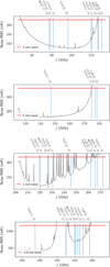 |
Fig. G.1 33 selected molecular lines by EMIR band. |
Appendix H Mutual information maps between lines and incident UV field
This section contains a figure, namely Fig. H.1, that is analyzed in the main text in Sect. 4.2.2. It is similar to Fig. 6, analyzed in Sect. 4.2.1. It shows that, for a given parameter subspace, the informative lines are different from those for ![$\[A_{V}^{\text {tot }}\]$](/articles/aa/full_html/2024/11/aa51588-24/aa51588-24-eq192.png) . Some lines such as the [CII] and 12CO lines are informative in a large fraction of the parameter space, while the 13CO and C18O lines are almost never useful. Overall, the mutual information values are much smaller than those for
. Some lines such as the [CII] and 12CO lines are informative in a large fraction of the parameter space, while the 13CO and C18O lines are almost never useful. Overall, the mutual information values are much smaller than those for ![$\[A_{V}^{\text {tot }}\]$](/articles/aa/full_html/2024/11/aa51588-24/aa51588-24-eq193.png) , which means that G0 is more difficult to constrain based on these line intensities.
, which means that G0 is more difficult to constrain based on these line intensities.
 |
Fig. H.1 Maps of mutual information of individual lines with the UV radiative field in function of the actual visual extinction |
![$\[A_{V}^{\text {tot }}\]$](/articles/aa/full_html/2024/11/aa51588-24/aa51588-24-eq194.png)
Appendix I Predicted log intensities and associated gradients
This section contains a figure analyzed in the main text in Sect. 4.2.3. Figure I.1 shows the integrated intensities fℓ(θ) as a function of ![$\[A_{V}^{\text {tot }}\]$](/articles/aa/full_html/2024/11/aa51588-24/aa51588-24-eq195.png) and G0. It explains the mutual information maps on
and G0. It explains the mutual information maps on ![$\[A_{V}^{\text {tot }}\]$](/articles/aa/full_html/2024/11/aa51588-24/aa51588-24-eq196.png) in Fig. 6 and on G0 in Fig. H.1. The predicted intensities are computed for Pth = 105 K cm−3, while the mutual information maps are computed for a pressure following a loguniform distribution on the [105, 5 × 10⁶] K cm−3 interval. However, they capture the main physical phenomena that drive mutual information. In a nutshell, this figure shows that to be informative for a physical parameter, a line needs both a good S/N and a large gradient with respect to the physical variable of interest. As the gradient information might not be clearly visible, we provide14 two figures that represent the absolute value of the partial derivative of the predicted log integrated intensities with respect to
in Fig. 6 and on G0 in Fig. H.1. The predicted intensities are computed for Pth = 105 K cm−3, while the mutual information maps are computed for a pressure following a loguniform distribution on the [105, 5 × 10⁶] K cm−3 interval. However, they capture the main physical phenomena that drive mutual information. In a nutshell, this figure shows that to be informative for a physical parameter, a line needs both a good S/N and a large gradient with respect to the physical variable of interest. As the gradient information might not be clearly visible, we provide14 two figures that represent the absolute value of the partial derivative of the predicted log integrated intensities with respect to ![$\[A_{V}^{\text {tot }}\]$](/articles/aa/full_html/2024/11/aa51588-24/aa51588-24-eq197.png) and G0, respectively. In other words:
and G0, respectively. In other words:
![$\[\text { one displays }\left|\frac{\partial \log f_{\ell}}{\partial A_V^{\text {tot }}}\right| \text { while the other displays }\left|\frac{\partial \log f_{\ell}}{\partial G_0}\right| \text {. }\]$](/articles/aa/full_html/2024/11/aa51588-24/aa51588-24-eq198.png) (I.1)
(I.1)
When compared with the mutual information maps in Fig. 6 and H.1, they highlight the fact that a high mutual information requires both a large S/N and a large gradient. This is easy to see for ![$\[A_{V}^{\text {tot }}\]$](/articles/aa/full_html/2024/11/aa51588-24/aa51588-24-eq199.png) and the first two transitions of 12CO, 13CO and C18O, for instance. For 12CO, the gradient quickly goes to zero, as the two lines become optically thick and saturate. To achieve a S/N > 1, 13CO lines require larger values of
and the first two transitions of 12CO, 13CO and C18O, for instance. For 12CO, the gradient quickly goes to zero, as the two lines become optically thick and saturate. To achieve a S/N > 1, 13CO lines require larger values of ![$\[A_{V}^{\text {tot }}\]$](/articles/aa/full_html/2024/11/aa51588-24/aa51588-24-eq200.png) . They eventually also become optically thick and saturate, but for much larger values of
. They eventually also become optically thick and saturate, but for much larger values of ![$\[A_{V}^{\text {tot }}\]$](/articles/aa/full_html/2024/11/aa51588-24/aa51588-24-eq201.png) than 12CO. Lines of C18O never saturate: their partial derivative is always greater than 10−2.
than 12CO. Lines of C18O never saturate: their partial derivative is always greater than 10−2.
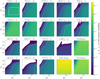 |
Fig. I.1 Predicted integrated intensities fℓ(θ) as a function of |
![$\[A_{V}^{\text {tot }}\]$](/articles/aa/full_html/2024/11/aa51588-24/aa51588-24-eq202.png)
Appendix J Additional line selection results
This section contains three figures described in the main text which are similar to Fig. 8, analyzed in Sect. 5.1. Each of them allows for a similar analysis applied either to another physical parameter (G0 instead of ![$\[A_{V}^{\text {tot }}\]$](/articles/aa/full_html/2024/11/aa51588-24/aa51588-24-eq203.png) ) or to a different observation simulator. Figure J.1 is analyzed in Sect. 5.2. It performs the analysis on G0 and shows that the most informative lines are different from those for
) or to a different observation simulator. Figure J.1 is analyzed in Sect. 5.2. It performs the analysis on G0 and shows that the most informative lines are different from those for ![$\[A_{V}^{\text {tot }}\]$](/articles/aa/full_html/2024/11/aa51588-24/aa51588-24-eq204.png) . In particular, the [CI] and [CII] lines are among the most informative.
. In particular, the [CI] and [CII] lines are among the most informative.
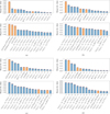 |
Fig. J.1 Line selection for G0 in an environment similar to the Horsehead pillar, for the reference use case (reference integration time and no scaling factor, κ, in the observation simulator). The analysis is performed for different regimes of |
![$\[A_{V}^{\text {tot}}\]$](/articles/aa/full_html/2024/11/aa51588-24/aa51588-24-eq205.png)
![$\[3 \leq A_{V}^{\text {tot }} \leq 24\]$](/articles/aa/full_html/2024/11/aa51588-24/aa51588-24-eq206.png)
![$\[3 \leq A_{V}^{\text {tot }} \leq 6\]$](/articles/aa/full_html/2024/11/aa51588-24/aa51588-24-eq207.png)
![$\[6 \leq A_{V}^{\text {tot }} \leq 12\]$](/articles/aa/full_html/2024/11/aa51588-24/aa51588-24-eq208.png)
![$\[12 \leq A_{V}^{\text {tot }} \leq 24\]$](/articles/aa/full_html/2024/11/aa51588-24/aa51588-24-eq209.png)
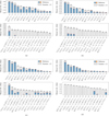 |
Fig. J.2 Line selection for |
![$\[A_{V}^{\text {tot }}\]$](/articles/aa/full_html/2024/11/aa51588-24/aa51588-24-eq210.png)
![$\[A_{V}^{\text {tot }}\]$](/articles/aa/full_html/2024/11/aa51588-24/aa51588-24-eq211.png)
![$\[3 \leq A_{V}^{\text {tot }} \leq 24\]$](/articles/aa/full_html/2024/11/aa51588-24/aa51588-24-eq212.png)
![$\[3 \leq A_{V}^{\text {tot }} \leq 6\]$](/articles/aa/full_html/2024/11/aa51588-24/aa51588-24-eq213.png)
![$\[6 \leq A_{V}^{\text {tot }} \leq 12\]$](/articles/aa/full_html/2024/11/aa51588-24/aa51588-24-eq214.png)
![$\[\left12 \leq A_{V}^{\text {tot }} \leq 24\right.\]$](/articles/aa/full_html/2024/11/aa51588-24/aa51588-24-eq215.png)
Figure J.2 is analyzed in Sect. 5.3. It shows how increasing the integration time affects the mutual information with ![$\[A_{V}^{\text {tot }}\]$](/articles/aa/full_html/2024/11/aa51588-24/aa51588-24-eq216.png) differently for all lines and couples of lines, and changes the ranking. Figure J.3 is analyzed in Sect. 5.4. It shows how including additional uncertainty sources in the observation simulator from Eq. 1 affects the mutual information of the considered lines with G0, and also changes the ranking. The two latter cases show that the simulator choice is critical to draw valid conclusions. In particular, they demonstrate the importance of using a model as realistic as possible. Additional results, including results for thermal pressure, Pth, which is not described in this paper, are available online15.
differently for all lines and couples of lines, and changes the ranking. Figure J.3 is analyzed in Sect. 5.4. It shows how including additional uncertainty sources in the observation simulator from Eq. 1 affects the mutual information of the considered lines with G0, and also changes the ranking. The two latter cases show that the simulator choice is critical to draw valid conclusions. In particular, they demonstrate the importance of using a model as realistic as possible. Additional results, including results for thermal pressure, Pth, which is not described in this paper, are available online15.
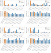 |
Fig. J.3 Line selection for G0 in an environment similar to the Horsehead pillar, for the uncertain geometry use case (reference integration time and addition of a scaling factor, κ, in the observation simulator). The analysis is performed for different regimes of |
![$\[A_{V}^{\text {tot}}\]$](/articles/aa/full_html/2024/11/aa51588-24/aa51588-24-eq217.png)
![$\[3 \leq A_{V}^{\text {tot }} \leq 24\]$](/articles/aa/full_html/2024/11/aa51588-24/aa51588-24-eq218.png)
![$\[3 \leq A_{V}^{\text {tot }} \leq 6\]$](/articles/aa/full_html/2024/11/aa51588-24/aa51588-24-eq219.png)
![$\[6 \leq A_{V}^{\text {tot }} \leq 12\]$](/articles/aa/full_html/2024/11/aa51588-24/aa51588-24-eq220.png)
![$\[12 \leq A_{V}^{\text {tot }} \leq 24\]$](/articles/aa/full_html/2024/11/aa51588-24/aa51588-24-eq221.png)
References
- Behrens, E., Mangum, J. G., Holdship, J., et al. 2022, ApJ, 939, 119 [NASA ADS] [CrossRef] [Google Scholar]
- Beirlant, J., Dudewicz, E. J., Györfi, L., et al. 1997, Int. J. Math. Statist. Sci., 6, 17 [Google Scholar]
- Blanc, G. A., Kewley, L., Vogt, F. P. A., & Dopita, M. A. 2015, ApJ, 798, 99 [Google Scholar]
- Bron, E., Roueff, E., Gerin, M., et al. 2021, A&A, 645, A28 [NASA ADS] [CrossRef] [EDP Sciences] [Google Scholar]
- Carter, M., Lazareff, B., Maier, D., et al. 2012, A&A, 538, A89 [NASA ADS] [CrossRef] [EDP Sciences] [Google Scholar]
- Clauset, A., Shalizi, C. R., & Newman, M. E. 2009, SIAM Rev., 51, 661 [NASA ADS] [CrossRef] [Google Scholar]
- Cormier, D., Madden, S., Lebouteiller, V., et al. 2015, A&A, 578, A53 [CrossRef] [EDP Sciences] [Google Scholar]
- Cover, T. M., & Thomas, J. A. 2006, Elements of Information Theory, 2nd edn. (Wiley-Interscience) [Google Scholar]
- de Mijolla, D., Viti, S., Holdship, J., Manolopoulou, I., & Yates, J. 2019, A&A, 630, A117 [NASA ADS] [CrossRef] [EDP Sciences] [Google Scholar]
- Einig, L., Pety, J., Roueff, A., et al. 2023, A&A, 677, A158 [NASA ADS] [CrossRef] [EDP Sciences] [Google Scholar]
- Galliano, F. 2018, MNRAS, 476, 1445 [NASA ADS] [CrossRef] [Google Scholar]
- Goicoechea, J. R., & Le Bourlot, J. 2007, A&A, 467, 1 [NASA ADS] [CrossRef] [EDP Sciences] [Google Scholar]
- Goicoechea, J. R., Santa-Maria, M. G., Bron, E., et al. 2019, A&A, 622, A91 [NASA ADS] [CrossRef] [EDP Sciences] [Google Scholar]
- Grassi, T., Nauman, F., Ramsey, J. P., et al. 2022, A&A, 668, A139 [NASA ADS] [CrossRef] [EDP Sciences] [Google Scholar]
- Gratier, P., Bron, E., Gerin, M., et al. 2017, A&A, 599, A100 [CrossRef] [EDP Sciences] [Google Scholar]
- Gratier, P., Pety, J., Bron, E., et al. 2021, A&A, 645, A27 [CrossRef] [EDP Sciences] [Google Scholar]
- Härdle, W., & Simar, L. 2007, in Applied Multivariate Statistical Analysis (Springer), 321 [Google Scholar]
- Heays, A. N., Bosman, A. D., & van Dishoeck, E. F. 2017, A&A, 602, A105 [NASA ADS] [CrossRef] [EDP Sciences] [Google Scholar]
- Hennebelle, P., & Falgarone, E. 2012, A&AR, 20, 1 [NASA ADS] [Google Scholar]
- Heyl, J., Butterworth, J., & Viti, S. 2023, MNRAS, 526, 404 [NASA ADS] [CrossRef] [Google Scholar]
- Holdship, J., Jeffrey, N., Makrymallis, A., Viti, S., & Yates, J. 2018, ApJ, 866, 116 [NASA ADS] [CrossRef] [Google Scholar]
- Holdship, J., Viti, S., Haworth, T. J., & Ilee, J. D. 2021, A&A, 653, A76 [NASA ADS] [CrossRef] [EDP Sciences] [Google Scholar]
- Holmes, C. M., & Nemenman, I. 2019, Phys. Rev. E, 100, 022404 [NASA ADS] [CrossRef] [Google Scholar]
- Ikeda, M., Oka, T., Tatematsu, K., Sekimoto, Y., & Yamamoto, S. 2002, ApJS, 139, 467 [NASA ADS] [CrossRef] [Google Scholar]
- Joblin, C., Bron, E., Pinto, C., et al. 2018, A&A, 615, A129 [NASA ADS] [CrossRef] [EDP Sciences] [Google Scholar]
- Johnson, R. W. 2001, Teach. Statist., 23, 49 [CrossRef] [Google Scholar]
- Kaplan, K. F., Dinerstein, H. L., Kim, H., & Jaffe, D. T. 2021, ApJ, 919, 27 [NASA ADS] [CrossRef] [Google Scholar]
- Kaufman, M. J., Wolfire, M. G., Hollenbach, D. J., & Luhman, M. L. 1999, ApJ, 527, 795 [Google Scholar]
- Kouiroukidis, N., & Evangelidis, G. 2011, in 2011 15th Panhellenic Conference on Informatics, IEEE, 41 [CrossRef] [Google Scholar]
- Kozachenko, L. F., & Leonenko, N. N. 1987, Probl. Pered. Inform., 23, 9 [Google Scholar]
- Kraskov, A., Stögbauer, H., & Grassberger, P. 2004, Phys. Rev. E, 69, 066138 [NASA ADS] [CrossRef] [Google Scholar]
- Le Petit, F., Nehme, C., Le Bourlot, J., & Roueff, E. 2006, ApJS, 164, 506 [NASA ADS] [CrossRef] [Google Scholar]
- Lundberg, S. M., & Lee, S.-I. 2017, in Advances in Neural Information Processing Systems, 30 (Curran Associates, Inc.) [Google Scholar]
- Mathis, J. S., Mezger, P. G., & Panagia, N. 1983, A&A, 128, 212 [NASA ADS] [Google Scholar]
- McElroy, D., Walsh, C., Markwick, A. J., et al. 2013, A&A, 550, A36 [NASA ADS] [CrossRef] [EDP Sciences] [Google Scholar]
- Miller, G. 1955, Information theory in psychology: Problems and methods [Google Scholar]
- Pabst, C., Goicoechea, J. R., Teyssier, D., et al. 2017, A&A, 606, A29 [NASA ADS] [CrossRef] [EDP Sciences] [Google Scholar]
- Palud, P., Einig, L., Le Petit, F., et al. 2023, A&A, 678, A198 [NASA ADS] [CrossRef] [EDP Sciences] [Google Scholar]
- Pandey, B., & Sarkar, S. 2017, MNRAS, 467, L6 [CrossRef] [Google Scholar]
- Pety, J., Guzmán, V. V., Orkisz, J. H., et al. 2017, A&A, 599, A98 [NASA ADS] [CrossRef] [EDP Sciences] [Google Scholar]
- Ramambason, L., Lebouteiller, V., Bik, A., et al. 2022, Inferring the HII Region Escape Fraction of Ionizing Photons from Infrared Emission Lines in Metal-Poor Star-Forming Dwarf Galaxies [Google Scholar]
- Ramos, A. A., Plaza, C. W., Navarro-Almaida, D., et al. 2024, MNRAS, 531, 4930 [NASA ADS] [CrossRef] [Google Scholar]
- Risacher, C., Güsten, R., Stutzki, J., et al. 2016, A&A, 595, A34 [NASA ADS] [CrossRef] [EDP Sciences] [Google Scholar]
- Röllig, M., Abel, N. P., Bell, T., et al. 2007, A&A, 467, 187 [Google Scholar]
- Roueff, A., Gerin, M., Gratier, P., et al. 2021, A&A, 645, A26 [NASA ADS] [CrossRef] [EDP Sciences] [Google Scholar]
- Roueff, A., Pety, J., Gerin, M., et al. 2024, A&A, 686, A255 [NASA ADS] [CrossRef] [EDP Sciences] [Google Scholar]
- Schreier, P. J. 2008, IEEE Trans. Signal Process., 56, 1327 [NASA ADS] [CrossRef] [Google Scholar]
- Shalev-Shwartz, S., & Ben-David, S. 2014, Understanding Machine Learning: From Theory to Algorithms, 1st edn. (Cambridge University Press) [CrossRef] [Google Scholar]
- Shannon, C. E. 1948, Bell Syst. Tech. J., 27, 379 [Google Scholar]
- Sheffer, Y., & Wolfire, M. G. 2013, ApJ, 774, L14 [NASA ADS] [CrossRef] [Google Scholar]
- Smirnov-Pinchukov, G. V., Molyarova, T., Semenov, D. A., et al. 2022, A&A, 666, L8 [NASA ADS] [CrossRef] [EDP Sciences] [Google Scholar]
- Thomas, A. D., Dopita, M. A., Kewley, L. J., et al. 2018, ApJ, 856, 89 [NASA ADS] [CrossRef] [Google Scholar]
- Tielens, A. G. 2005, The Physics and Chemistry of the Interstellar Medium (Cambridge University Press) [CrossRef] [Google Scholar]
- Wakelam, V., Herbst, E., Loison, J. C., et al. 2012, ApJS, 199, 21 [Google Scholar]
- Walters-Williams, J., & Li, Y. 2009, in Rough Sets and Knowledge Technology: 4th International Conference, RSKT 2009, Gold Coast, Australia, July 14–16, 2009. Proceedings 4, Springer, 389 [Google Scholar]
- Wehrl, A. 1978, Rev. Mod. Phys., 50, 221 [NASA ADS] [CrossRef] [Google Scholar]
- Wu, R., Bron, E., Onaka, T., et al. 2018, A&A, 618, A53 [NASA ADS] [CrossRef] [EDP Sciences] [Google Scholar]
All Tables
All Figures
|
Fig. 1 A simple synthetic example of a joint distribution on the couple (Θ, Y). Top: contour levels of the PDF of the joint distribution with lognormal marginals and a clear correlation. Three observed values are indicated with horizontal lines. Bottom: comparison of the distribution on Θ before any observation (prior, in dashed black) and for the three y values (conditional distributions, in colors). |
| In the text | |
|
Fig. 2 Venn diagram representation of the differential entropy h (Θ) (and h (Y)) of the conditional differential entropy h (Θ|Y) (and h (Y|Θ)), and of the mutual information I (Θ, Y). |
| In the text | |
|
Fig. 3 Violin plots of the S/N of the spectral lines considered in this study, with the S/N defined as fℓ(θ)/σa,ℓ. The EMIR lines are displayed in blue on the left, while the [CI] and [CII] lines are shown in orange on the right. Top: S/N distributions for a loguniform distribution on the full validity intervals on the physical parameters. The considered line filter only keeps lines that have a 99% percentile S/N greater than 3. This threshold is indicated with the horizontal dashed black line, and the actual 99% percentile S/N is shown with a short black line for each line. Bottom: S/N distributions in an environment similar to the Horsehead pillar, for the same lines. The lines are ranked by decreasing median S/N, indicated in red. |
| In the text | |
|
Fig. 4 Evolution of mutual information between the visual extinction |
| In the text | |
|
Fig. 5 Evolution of mutual information between the visual extinction |
| In the text | |
|
Fig. 6 Maps of mutual information of individual lines with the visual extinction in function of the actual visual extinction |
| In the text | |
|
Fig. 7 Mutual information maps between |
| In the text | |
|
Fig. 8 Line selection for |
| In the text | |
|
Fig. 9 Comparison between the amount of information on G0 provided by the five best couples of lines in Fig. J.3 (colored bars) and their line ratio (hatched bars). |
| In the text | |
|
Fig. B.1 Entropy definition illustration for different example distributions on θ. The first two rows show the PDF of uniform distributions on different sets, and the last row of Gaussian distributions. The distributions in one column have an equal differential entropy h (Θ) whose value depends on a positive constant c. Each arrow indicates a gain of 1 bit of information, i.e., a decrease in the entropy of 1 bit. In the last row, the variance in both horizontal and vertical directions is denoted σ2, and the correlation coefficient ρ. |
| In the text | |
|
Fig. C.1 Comparison of four mutual information estimators applied on the simple lognormal bivariate distribution presented in Sect. 2.1. The dashed black line corresponds to the theoretical value. The 1σ interval is not shown for the simple canonical correlation-based estimator as it appears to be asymptotically biased. The Kraskov estimator (in blue) converges to the correct value for a large number of simulated observations N. The CC estimator is used with three preprocessing: no preprocessing, log and Gaussian reparametrization. As the joint distribution is non-Gaussian, the no-preprocessing case does not converge to the theoretical value. However, the other two preprocessing transform it to a Gaussian, the associated CC estimators converge to the theoretical value for large values of N. |
| In the text | |
|
Fig. D.1 Illustration of the k-NN estimators for k = 3. For each green point, the distance to its third nearest neighbor, denoted εd, is represented. A low distance implies a locally high density. |
| In the text | |
|
Fig. D.2 Graph of the digamma function ψ on |
| In the text | |
|
Fig. D.3 Illustration of the k-NN estimator of mutual information for k = 3. In the first panel, the mutual information is high so nx and ny are close to k. In the second panel, the mutual information is low so nx and ny are much higher than k. |
| In the text | |
|
Fig. E.1 Comparison between the estimation of variances for different numbers of samples for a bivariate normal distribution with ρ = 0.8. Red markers: variances estimated with several different datasets. Black markers: variances estimated with subsampling of a single dataset. Black line: regression line to predict the variance for any number of samples. The limit of saturation indicated by a dashed line corresponds to the number of samples for which the relationship of Eq. E.3 no longer holds. |
| In the text | |
|
Fig. G.1 33 selected molecular lines by EMIR band. |
| In the text | |
|
Fig. H.1 Maps of mutual information of individual lines with the UV radiative field in function of the actual visual extinction |
| In the text | |
|
Fig. I.1 Predicted integrated intensities fℓ(θ) as a function of |
| In the text | |
|
Fig. J.1 Line selection for G0 in an environment similar to the Horsehead pillar, for the reference use case (reference integration time and no scaling factor, κ, in the observation simulator). The analysis is performed for different regimes of |
| In the text | |
|
Fig. J.2 Line selection for |
| In the text | |
|
Fig. J.3 Line selection for G0 in an environment similar to the Horsehead pillar, for the uncertain geometry use case (reference integration time and addition of a scaling factor, κ, in the observation simulator). The analysis is performed for different regimes of |
| In the text | |
Current usage metrics show cumulative count of Article Views (full-text article views including HTML views, PDF and ePub downloads, according to the available data) and Abstracts Views on Vision4Press platform.
Data correspond to usage on the plateform after 2015. The current usage metrics is available 48-96 hours after online publication and is updated daily on week days.
Initial download of the metrics may take a while.