| Issue |
A&A
Volume 665, September 2022
|
|
|---|---|---|
| Article Number | A131 | |
| Number of page(s) | 22 | |
| Section | Interstellar and circumstellar matter | |
| DOI | https://doi.org/10.1051/0004-6361/202243657 | |
| Published online | 21 September 2022 | |
Multiline observations of CH3OH, c-C3H2, and HNCO toward L1544
Dissecting the core structure with chemical differentiation
1
Max-Planck-Institut für Extraterrestrische Physik,
Giessenbachstr. 1,
85748
Garching bei München, Germany
e-mail: This email address is being protected from spambots. You need JavaScript enabled to view it.
2
Ural Federal University,
620002,
19 Mira street,
Yekaterinburg, Russia
Received:
28
March
2022
Accepted:
19
May
2022
Abstract
Context. Pre-stellar cores are the basic unit for the formation of stars and stellar systems. The anatomy of the physical and chemical structures of pre-stellar cores is critical for understanding the star formation process.
Aims. L1544 is a prototypical pre-stellar core that shows significant chemical differentiation surrounding the dust peak. We aim to constrain the physical conditions at the different molecular emission peaks. This study allows us to compare the abundance profiles predicted from chemical models with the classical density structure of the Bonnor-Ebert (BE) sphere.
Methods. We conducted multi-transition pointed observations of CH3OH, c-C3H2, and HNCO with the IRAM 30m telescope toward the dust peak and the respective molecular peaks of L1544. Using this data set, with nonlocal-thermodynamic-equilibrium radiative transfer calculations and a one-dimensional model, we revisit the physical structure of L1544 and benchmark the observations with the abundance profiles from current chemical models.
Results. We find that the HNCO, c-C3H2, and CH3OH lines in L1544 trace progressively higher-density gas, from ~104 to several times 105 cm−3. Particularly, we find that to produce the observed intensities and ratios of the CH3OH lines, a local gas density enhancement above that of the BE sphere is required. This suggests that the physical structure of an early-stage core may not necessarily follow a smooth decrease in gas density profile locally, but can be intercepted by clumpy substructures that surround the gravitational center.
Conclusions. Multiple transitions of molecular lines from different molecular species can provide a tomographic view of the density structure of pre-stellar cores. The local gas density enhancement deviating from the BE sphere may reflect the impact of accretion flows that appear asymmetric and are enhanced at the meeting point of large-scale cloud structures.
Key words: ISM: clouds / ISM: individual objects: L1544 / ISM: structure / ISM: abundances
© Y. Lin et al. 2022
 Open Access article, published by EDP Sciences, under the terms of the Creative Commons Attribution License (https://creativecommons.org/licenses/by/4.0), which permits unrestricted use, distribution, and reproduction in any medium, provided the original work is properly cited.
This article is published in open access under the Subscribe-to-Open model.
Open Access funding provided by Max Planck Society.
1 Introduction
Dense cores, with hydrogen gas densities of ≳104 cm−3 and physical scales of 0.1 pc, are the birthplaces of stars and stellar systems (Bergin & Tafalla 2007; di Francesco et al. 2007). Pre-stellar cores represent an early phase of core evolution after the starless core stage, and they appear gravitationally bound but still without protostars. Understanding physical structures of pre-stellar cores can provide important constraints on the initial condition for the formation of low-mass stars. During the core evolution, in accordance with variations in physical structures, chemical compositions can vary significantly inside the core (Suzuki et al. 1992; van Dishoeck & Blake 1998; Ceccarelli et al. 2007; Bergin & Tafalla 2007). Furthermore, the environment also has an effect on the chemical structure of the embedded core (Spezzano et al. 2016, 2020). A combination of multiple transitions of different molecular species provides an indispensable diagnosis kit for analyzing both the past and current physical properties of dense cores.
The gravitational collapse of dense cores leads to the formation of low-mass stars, but the detailed process of the collapse remains elusive. One of the widely used models is the Bonnor-Ebert (BE) sphere (Keto & Caselli 2010; Broderick & Keto 2010). Essentially, the model suggests that cores are hydrostatic objects during gravitational contraction that are balanced by the thermal pressure complemented with the turbulence kinetic energy (Nakano 1998). Subsequent core evolution is caused by turbulence damping, during which the core remains in quasi-static equilibrium. Additional support from the magnetic field allows for an increment of the central gas density of the core (Keto & Field 2005). The density profile of a BE sphere has a plateau in the center followed by a r−2 decrease in outer regions, and the scale of the central plateau decreases as the collapse proceeds (Keto & Caselli 2010). In contrast to this quasi-static model, the turbulent origin suggests that core formation is driven by compressive gas motions, a more dynamical process (Mac Low & Klessen 2004). Pre-stellar cores are pristine sites for distinguishing between the competing core formation models, and they also provide unique test beds for understanding the complex chemistry of molecular gas.
Recent Atacama Large Millimeter Array (ALMA) observations of the innermost regions of pre-stellar cores have resolved or tentatively detected small-scale (≲1000au−0.01 pc) substructures (e.g., Ohashi et al. 2018; Caselli et al. 2019; Tokuda et al. 2020; Sahu et al. 2021, see the recent review of Pineda et al. 2022). While the origin of the substructures is still under debate, a BE sphere description of pre-stellar cores may be an oversimplification except when describing the featureless cores. The substructures can also exhibit large chemical differences (e.g., Tatematsu et al. 2020), suggesting that they are at different evolutionary stages. It is also uncertain whether these observed substructures will coalesce in a later stage or collapse individually (Sahu et al. 2021). In general, turbulent fragmentation predicts a high level of multiplicity inside the core (Goodwin et al. 2004; Offner et al. 2010; Pineda et al. 2022), but how fragmentation starts and evolves remains unclear. Investigations into the physical structure of pre-stellar cores, in which gravitational contraction has just started to critically shape the core gas, can provide important constraints on this aspect.
L1544 is a well-studied late-stage pre-stellar core. Its physical structure seems to be well described by the BE sphere (Keto & Caselli 2010; Keto et al. 2014, 2015; Caselli et al. 2022). Inside the core, gravitational collapse has started, showing infall motions, but the central singularity has not yet formed (Myers et al. 1996; Tafalla et al. 1998; Caselli et al. 2002b, 2019, 2022; Keto & Caselli 2010). The chemical composition of L1544 exhibits significant spatial differentiation: the inner core is characterized by a high deuterium fraction (Caselli et al. 2002b,a; Crapsi et al. 2007; Chacón-Tanarro et al. 2019; Redaelli et al. 2019) and, surrounding the dust peak (≳0.02 pc) at different positions, the core displays characteristic emission peaks of molecules (Fig. 1, Spezzano et al. 2016, 2017; Jiménez-Serra et al. 2016). The three molecular peaks are the CH3OH peak, the c-C3H2 peak, and the HNCO peak, which also appear to be emission peaks for several other chemically related species of the three respective molecules (Spezzano et al. 2017). The physical and chemical mechanisms behind the marked chemical differentiation are not fully known. The nonuniform illumination by the large-scale radiation field seems to play an important role, resulting in the distinct emission peaks of CH3OH and c-C3H2, by influencing the amount of gas-phase atomic carbon; this was verified using a sample of pre-stellar cores that show different spatial distributions of CH3OH and c-C3H2 emission (Spezzano ret al. 2020).
Because chemical processes are tightly connected with physical properties, probing the excitation conditions of these molecules can provide important clues as to their chemical differentiation (van Dishoeck & Blake 1998; Caselli & Ceccarelli 2012; Jørgensen et al. 2020). To this end, we have carried out multiline observations of CH3OH, c-C3H2, and HNCO toward L1544 (Table 1), targeting the dust peak and the molecular peaks (Fig. 1, Table 2). By incorporating the abundance profiles predicted by chemical models (Sipilä et al. 2016; Vasyunin et al. 2017) in full radiative transfer calculations with spherical symmetry, we gauge how well the current chemical models can reproduce the observed line emission.
The paper is laid out as follows: in Sect. 2 information regarding observations and the data reduction procedure are presented. The obtained molecular lines are described in Sect. 3.1. In Sects. 3.2.1 and 3.2.2 calculations of radiative transfer models are elaborated, providing constraints on the physical properties. Lastly, results from different radiative transfer models and from different molecular species are discussed in Sect. 4, and our conclusion and outlook are presented in Sect. 5.
Observed lines.
2 Observations
Observations of the molecular lines listed in Table 1 were taken with the IRAM 30 m telescope. All the lines, except CH3OH 2K− 1K, were observed with pointed observations toward the dust peak and the molecular peaks of L1544. These observations were conducted on January 28–29, March 1, and April 17, 2021 (Project: 101-20, PI: Silvia Spezzano) using Eight MIxer Receiver (EMIR) with a fast fourier transform spectrometers backend (FTS) and a tracked frequency switch mode. The typical precipitable water vapor is 2–3 mm. The spectral resolution is 0.10 km s−1 at 145 GHz, and the corresponding half-power full-width (HPFW) beam size is ~17′′ (listed in Table 1). The achieved rms level (1σ) is ~15–25 mK. Typical calibration uncertainties are 20%. We used the CLASS software package in GILDAS for the data reduction. A first-order baseline subtraction was applied. The antenna temperatures ( ) were converted to main-beam brightness temperatures (Tmb) with efficiencies interpolated according to the online ηmb table1 for different line frequencies. We also adopted the archival IRAM 30m telescope mapping observations of CH3OH(2−1) lines of L1544, some of which were previously published by Bizzocchi et al. (2014) and Spezzano et al. (2016).
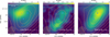 |
Fig. 1 Integrated intensity maps (in color scale) of CH3OH-E 2−1,2−1−1,1, c-C3H2 З2,2−31,3, and HNCO 40,4−30,з (from left to right) observed by the IRAM 30 m telescope, showing the different locations of the molecular peaks (Table 2, Spezzano et al. 2017). The contour levels (in orange) show 3.2 × 10²¹, 4.3 × 10²¹, 5.9 × 10²¹, 8.1 × 10²¹, 1.1 × 10²², 1.5 × 10²², and 2.1 × 1022 cm−2 of the molecular hydrogen column density ( |

Coordinates of the dust peak and three molecular peaks.
3 Results
3.1 Spectra at the dust peak and molecular peaks
The obtained molecular lines at the dust peak and the molecular peaks are shown in Figs. 2 and 3. All the Eup ≲ 20 Κ transitions of CH3OH were detected above 5σ toward the dust peak and all three molecular peaks. These lines have critical densities of ≲1.5 × 105 cm−3. Toward the CH3OH peak, the 30,з−20,2 line (Euρ ~ 27 K, ncrit ~ 2.6 × 105 cm−3) was also detected.
The c-C3Η2 and HNCO lines were only observed toward the dust peak and the respective molecular peaks. At the dust peak and c-C3Η2 peak, all four lines of c-C3Η2 in Table 1 were detected. The 43,2−32,1 and З3,0−22,1 lines at the dust peak show an emission dip at the VLSR of L1544 (7.19 kms−1). At the c-C3Η2 peak, there is also a dip in the З3,0−22,1 line profile, but not in the 43,2−32,1 line. As for the four HNCO lines, at the dust peak and HNCO peak all the lines were detected except the line of the highest energy level (80,8−70,7), and they have a signal-to-noise ratio of >5 (Fig. 3).
We fitted the molecular line profiles with Gaussian models, the parameters of which are listed in Tables 3 and 4. The obtained line widths (σV) are mostly ~0.15 ± 0.03 km s−1, with no significant variations between lines of different molecular species or different positions.
3.2 Radiative transfer modeling
3.2.1 RADEX models of CH3OH, c-C3H2, and HNCO lines
We first used one-component nonlocal-thermodynamic-equilibrium (non-LTE) models to describe the emission of the observed lines. Specifically, for HNCO, C3Η2, and CH3OH molecules, we generated RADEX (van der Tak et al. 2007) model grids, for column densities (Ν/Δυ with Δυ)= 1 kms−1) in the range Ν = 1011 to 1015 cm−2 (with 60 logarithmically spaced uniform intervals), hydrogen gas densities in the range 103 to 108 cm−3 (with 100 logarithmically spaced uniform intervals), and kinetic temperatures in the range 3–100 Κ (with 80 uniform intervals). The external radiation field was taken to be the cosmic background at 2.73 K. The molecular data files for CH3OH and HNCO were taken from the Leiden database, with collisional rates measured by Rabli & Flower (2010) and Sahnoun et al. (2018), respectively. For c-C3Η2, we adopted the newly updated collisional rates, which go down to 8 Κ (Ben Khalifa et al. 2019).
In the RADEX models, the line width was taken as 1 km s−1 for all the grids of parameters. The molecular column densities were further obtained by multiplying the fitted N/Δυ with the line width of each molecule. We used a linear interpolator to estimate the line intensities for parameters in between the intervals to better constrain the parameters and to allow for a continuous examination of the parameter space. Nevertheless, the accuracy of the best-fit parameters remains limited by the resolution of the grid. We employed the Markov chain Monte Carlo (MCMC) method with an affine invariant sampling algorithm2 (Foreman-Mackey et al. 2013) to perform the fitting (Lin et al. 2022). We initially kept all three parameters, Tkin, n(H2), and Nmol, as free parameters to fit with. For HNCO, we find the considered lines do not provide a good constraint on Tkin. We then assumed Tkin follows a normal distribution centering at 10 K and with a standard deviation of 5 K (N(µ = 10 K, σ = 5 K)). For the other parameters, the priors were assumed to be uniform distributions. We used a likelihood distribution function that takes observational thresholds into account (detection limit, as listed in Tables 3 and 4); the formulas follow
 (1)
(1)
where pi stands for the probability that the ith data point is a robust detection and pj the probability that the jth data point is an upper limit; we adopted the normal distribution as the likelihood function
![Mathematical equation: ${p_i} \propto \exp \,\left[ { - {1 \over 2}{{\left( {{{f_i^{{\rm{obs}}} - f_i^{{\rm{model}}}} \over {\sigma _i^{obs}}}} \right)}^2}} \right]\,{\rm{\Delta }}{f_i}$](/articles/aa/full_html/2022/09/aa43657-22/aa43657-22-eq3.png) (2)
(2)
![Mathematical equation: ${p_i} \propto \int_{ - \infty }^{f_{\lim ,j}^{{\rm{obs}}}} {\exp \,\left[ { - {1 \over 2}{{\left( {{{{f_j} - f_j^{{\rm{model}}}} \over {{\sigma _j}}}} \right)}^2}} \right]\,{\rm{d}}{f_j}} $](/articles/aa/full_html/2022/09/aa43657-22/aa43657-22-eq4.png) (3)
(3)
in which  (or fj) stands for the observed intensity (or intensity upper limit) obtained from the Gaussian fit,
  (or
(or  ) is the model intensity,
  is the standard error of the observed intensity, which was adopted as the fitted 1σ error of the Gaussian fit, σj is the standard error of the 1σ noise level, Δfi· is the data offset from the true value of fi, and dfj is the integrated flux probability up to the detection threshold,
  .
.
The starting points (initialization) for the chains were chosen to be the parameter set corresponding to a global;χ2 minimum calculated between the grid models and the observed values. The “burn-in” phase in the MCMC chains was included, and we also conducted several resets of the starting points to ensure the final chains are reasonably stable around the maximum of the probability. The posterior distributions of the parameters for all the molecules and at different locations are shown in Figs. A.1–A.4 The best-fit parameters are listed in Table 5 for the dust peak and the molecular peaks.
To account for the different beam sizes of the observed lines and the possible beam dilution effect, we tested the modeling by excluding the coarser resolution lines in Table 1, specifically for CH3OH the three J =2−1 lines at ~ 96 GHz and for c-C3H2 the 31,2−22,1 line. We find that the derived parameters are similar to the fiducial case where the lines are included in the fit (without correction of the beam dilution). The emission of these lower frequency lines is likely more extended than the respective finest beam size listed in Table 1, as also indicated by the 30m mapping observations in Spezzano et al. (2017) and the maps obtained from Northern Extended Millimeter Array (NOEMA) in Punanova et al. (2018), so the beam dilution effect is likely not significant. For HNCO lines, if we assume the emitting area is comparable with the finest beam among the lines (~14′′) and scale the intensities of lines with coarser resolution, we arrive at lower gas densities (≲104 cm−3). However, again, these lower frequency lines likely have extended emission that makes the beam dilution effect not as significant as the results derived by the rescaled intensities. Therefore, in Table 5 we list derived parameters based on line intensities without beam dilution correction. In Sect. 3.2.2, we use full radiative transfer models and generate line cubes following the structure of L1544, and we account for the varying beam sizes for comparisons with observations (Appendix B).
In addition, the mapping observations of J = 2−1 CH3ΟΗ Ε type lines, in which 2−1,2−1−1,1 and 20,2−20,1 were detected, were used to derive an n(Η2) map and an  map. These maps are shown in Fig. 4. It can be seen from the n(Η2) map that there is a prominent density enhancement centralized at the CH3OH peak. The regions with enhanced gas densities at the dust peak, the HNCO peaks, and the c-C3H2 peaks are less extended than toward the CH3OH peak. The
  values in Fig. 4 are in the range 1.0–7.9 × 1013 cm−2, which is consistent with that reported by Bizzocchi et al. (2014) and Vastel et al. (2014).
To further probe the physical properties at the CH3OH peak in detail, we used the high-angular-resolution observations of CH3OH J = 2−1 lines toward the CH3OH peak (Punanova et al. 2018). The spectral cube contains data combined from NOEMA and the 30m telescope, achieving a resolution of ~700 au. The derived n(Η2) map and  maps are shown in Fig. 5. The density enhancements in the n(Η2) map are located mostly southwest of the column density peak, facing the core center and reaching ~106 cm−3.
 |
Fig. 2 Observed CH3OH spectra at the dust peak and at the molecular peaks. The spectra are arranged in order of increasing frequency. Vertical dotted lines indicate VLSR = 7.19 kms−1. |
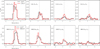 |
Fig. 3 Observed c-C3H2 and HNCO spectra at the dust peak and at the molecular peaks. The spectra are arranged in order of increasing frequency. Vertical dotted lines indicate VLSR = 7.19 kms−1. |
Gaussian profile parameters for lines at the c-C3H2 peak and the CH3OH peak.
Gaussian profile parameters for lines at the dust peak and the HNCO peak.
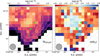 |
Fig. 4 Derived CH3OH column density map and hydrogen volume density from RADEX modeling. The contours (in gray) are NH2 levels, the same as those in Fig. 1. The markers in blue represent the dust peak (diamond), molecular emission peaks of CH3OH (three-branched triangle), HNCO (upward pointing triangle), and c-C3H2 (plus sign). |
3.2.2 Full radiative transfer modeling with LOC
While with RADEX modeling we constrain physical parameters with a one-component non-LTE radiative transfer approximation that retains the assumption of local excitation, to understand the mutual impact of molecular abundance profiles and the gas density distribution on the resultant line intensities (and ratios), we adopted full radiative transfer calculations using LOC (line transfer with OpenCL; Juvela 2020). In LOC, deterministic ray tracing and accelerated lambda iterations (Rybicki & Hummer 1991) are employed to model the radiative transfer process. We used the one-dimensional model in LOC, which considers a spherically symmetric distribution of physical structures, characterized by volume density, ρ(r), kinetic temperature, T(r), and velocity field, including both micro-turbulence, σturb, and radial velocity, V(r).
We adopted the parameterized forms of ρ(r), T(r), and V(r) following Keto & Caselli (2010) for L1544, which are shown in Fig. 6. The core radius is assumed to be 0.3 pc. In the modeling, linear discretization was used for the grids with a physical resolution of 60 au. We then convolved the output spectral cube with the corresponding observational beam for each frequency. We started the modeling with the radial abundance profiles predicted from the chemical models in Vasyunin et al. (2017) for CH3OH and from Sipilä et al. (2015, 2016) for C3H2 and HNCO. Examples of the abundance profiles are shown in Fig. 7 for epochs of 0.1, 0.2, 0.4, and 0.8 Myr. For CHЗOH abundance profiles, we adopted the results from Vasyunin et al. (2017) due to the fact that their treatment of CHЗOH formation and reactive desorption is more comprehensive as they took into account the change in reactive desorption with different surface compositions, following experimental work by Minissale et al. (2016). In both models, a static physical model of the core is adopted following Keto & Caselli (2010) and the chemistry is treated independently for different gas density layers. Initial elemental abundances are based on Wakelam & Herbst (2008; see also Semenov et al. 2010). For more details regarding the two chemical models, as well as the differences between them, we refer the readers to the original papers of Sipilä et al. (2015, 2016) and Vasyunin et al. (2017).
Comparisons between the modeled spectra and the observed line intensities are shown in Figs. B.1–B.7. For CH3OH, in general, the abundance profiles from chemical models produce spectra in excess of intensities and show significant self-absorption, which is not reflected by the observations. The four to five times larger column densities predicted by the chemical models compared to that estimated from observations of CH3OH in L1544 (Vastel et al. 2014) were also initially noted by Vasyunin et al. (2017). However, merely scaling down the abundance profile does not give a much better match (see Fig. B.2, where the abundance is scaled down by a factor of 5, hereafter model A). In particular, the intensities of CH3OH 30-3−1 and 20−2−1 around Vlsr Still show negative emission. Examination of the excitation temperature profiles shows that, for these two lines, Tex drops below the cosmic microwave background temperature (TCMB) beyond ~0.015 pc (Fig. 8, left panel), becoming anti-inverted. Also, the intensity of the 10−1−ı line is significantly underestimated compared to the other lines. Given the characteristics of the energy levels of E-tyρe CH3OH (Lees 1973; Kalenskii & Kurtz 2016), this is expected to some extent since these transitions have upper levels in the side ladders and lower levels in the main ladder, and the latter tends to be overpopulated, causing a lowTex of the transitions when the gas densities are low.
The uncertainties of the abundance of CH3OH of current chemical models are mainly due to the assumptions on reactive desorption rates as well as on the adoption of a static core (Vasyunin et al. 2017). As noted by Vasyunin et al. (2017), when dynamical evolution is taken into consideration, during which the gas density is enhanced due to gravitational collapse, there will be less CH3OH produced on grains at early times since CO freeze-out is less efficient in a low-density environment. Noting this and the differences between modeled spectra and observations, we attempted to adjust the combination of the radial abundance profile and the gas density profile to generate spectra that match the observed intensities. Based on the RADEX results, the n(Η2) seen by CH3OH lines at all molecular peaks are similar to that the dust peak. It is likely that at these molecular peaks, which are ~0.02pc from the dust peak, there are localized gas density enhancements, causing the emission of the CH3OH lines (see also Bacmann & Faure 2016 for CH3OH lines in other pre-stellar cores). We therefore modified the radial gas density profile (hereafter the modified density model) by adding a local density increment of 5 × 105 cm−3 with a width of 0.025 pc centered at ~0.03 pc from the dust peak. The width was chosen to match the n(Η2) map from NOEMA observations (Fig. 9) and is close to the 30m beam HPFW at the frequencies of 2K−1K lines. The resultant “perturbed” radial density profile is shown in Fig. 9. Such a modified density profile, in combination with a scaled-down (by a factor of 10) radial abundance profile (at the 0.8 Myr epoch from Vasyunin et al. 2017), can reproduce the intensities of most CH3OH lines well (hereafter model B) and those of the 10−1−1 and 20−2−1 lines within a factor of ~2. With the enhanced density, the 20−2−1 line now turns into emission and the 10−1−1 line exhibits a higher intensity (Fig. 10). We note that the combination of parameters used for the modified density model is not unique: a change in the width and/or absolute value of the density enhancement with a different abundance profile may also produce spectra that fit the observed lines well. The point is that by varying only the abundance profiles we cannot qualitatively match the CH3OH emission lines. Our choice of parameters is guided by the n(Η2) map derived from the high-angular-resolution NOEMA observations In Vasyunin et al. (2017), formation of CH3OH in the gas phase is most efficient at gas densities of ~104–105 cm−3, where CO molecules start to catastrophically freeze out. Indeed, from the NOEMA results of the n(Η2) and  maps (Fig. 5), the highest n(Η2) values do not correspond to the highest
  This is a consistent result, showing that CH3OH is likely more enhanced in moderate gas density regimes, while an enhanced gas density with a possible local reduction in gas temperature due to increased gas-dust coupling can promote the depletion of CH3OH. The impact of the density enhancement on the physical and chemical properties of L1544 should be investigated in the future with high-angular-resolution observations.
The inclusion of a density enhancement that better matches the data was mainly driven by the comparisons with the 20−1−1 and 10−1−1 lines, which have the highest ncrit of all the CH3OH lines. The four J0−J−1 lines are the most sub-thermally excited lines, as can be seen from their Tex profile in comparison with T(r) in Fig. 8. We compared the Tex profiles from the modified density profile model and the original density model in Fig. 8. It can be seen that the inclusion of the density enhancement at 0.015–0.040 pc leads to an increase in Tex at these radii, which levels up the emission of the strongly sub-thermally excited lines to match the observations. The modeled radial profiles of  from best-fit model A and model Β are shown in Fig. 11: with the density enhancement, the peak of
  is also more prominent and appears closer to the 0.02 pc radius.
For c-C3H2 and HNCO, the abundance profiles from chemical models in Sipilä et al. (2015) can reproduce the observed line intensities relatively well (Figs. B.4 and B.6). The line intensities at the dust peak can be predicted within 30% by the abundance profile at 0.1 Myr, while the line intensities at the HNCO peak are systematically underestimated within a factor of 2. We find that a factor of 2–5 increment in the abundance profile, depending on the epoch of the abundance profile used, will match the observations at the HNCO peak better. The results are shown in Fig. B.5. For the c-C3H2 lines, the modeled spectra show the best consistency with the observed line intensities (Fig. B.4), similar to what was presented by Sipilä et al. (2016). The observed line intensities at the dust peak are within ~20% of the modeled spectra for the abundance profile at 0.1 Myr. For the c-C3H2 peak, a factor of 3 increment in the abundance profile can produce the observed line intensities better, which is shown in Fig. B.5. The fact that HNCO and c-C3H2 lines do not need a modification of density profile to fit the model spectra indicates that these lines indeed mostly originate from the bulk volume of gas in the outer regions of L1544, without a prominent preferential emission region of either denser nor diffuse gas layers. This corroborates our analysis from the RADEX modeling, described in Sect. 3.2.1.
Derived gas properties using RADEX models at the dust peak and molecular peaks.
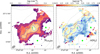 |
Fig. 5
|


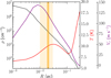 |
Fig. 6 Radial profiles of gas density, temperature, and infall velocity. The light orange shaded region indicates the beam area with which the molecular peaks are identified, centered at an offset of 0.02pc (with respect to the dust peak), shown by a vertical orange line. |
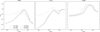 |
Fig. 7 Radial abundance profiles from chemical models. Left and middle panels: radial abundance profiles of c-C3H2 and HNCO for selected epochs, predicted by chemical modeling in Sipilä et al. (2015). Right panel: radial abundance profiles of CH3OH, predicted by chemical modeling in Vasyunin et al. (2017). |
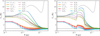 |
Fig. 8 Comparison between T(r) (gray line) and the radial profile of Tex of all CH3OH lines from the best-fit model with modified radial density profiles (left) and original density profiles (right). The best-fit abundance profiles are at 0.8 Myr from Vasyunin et al. (2017), which were scaled down by a factor of 5 and 10 in the left and right panels (of model A and model B), respectively. The cosmic microwave background temperature of 2.73 Κ is also indicated (black horizontal line). The four J0−J−1 lines are shown with thicker line widths. |
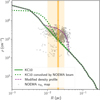 |
Fig. 9 Modified radial density profile (purple) in comparison with the original and beam-convolved radial density profiles (green) of L1544 established in Keto & Caselli (2010) (indicated by KC10 in the legend). Gray crosses indicate the gas density values measured from the n(Η2) map, as in Fig. 5. The light orange shaded region indicates the beam area with which the molecular peaks are identified, centered at an offset of 0.02 pc (with respect to the dust peak) and shown by a vertical orange line. |
4 Discussion
4.1 CH3OH, c-C3H2, and HNCO: tracing gas layers of different densities across L1544
From the radiative transfer modeling, we find that the gas densities seen by CH3OH, c-C3H2, and HNCO are very different (Table 5). The lines of CH3OH are excited at the highest gas densities, reaching up to 3–7 × 105 cm−3, both at the dust peak and at the molecular peaks. Such high-density gas at the dust peak and c-C3H2 peak is also associated with a low kinetic temperature, below 10 K, while at the HNCO and CH3OH peaks the kinetic temperature is ~15 K. On the other hand, modeling of the c-C3H2 and HNCO lines indicates gas densities of several times 104 cm−3, suggesting that these lines mainly originate from the outer, less dense layers of the pre-stellar core. Toward the dust peak, the kinetic temperatures indicated by the HNCO and c-C3H2 lines, although not well constrained, are likely above 10 Κ (Figs. A.2−A.4). This is consistent with the fact that the outer gas layers of pre-stellar cores have higher temperatures with respect to the central region (with temperatures close to 6 K; Crapsi et al. 2007).
The C3H2 lines have been suggested to be good density probes for dark molecular clouds (104−105 cm−3; Avery 1987; Cox et al. 1989). The gas densities toward starless and protostel-lar cores probed by multiple transitions of c-C3H2 are usually several 104 cm−3 (Cox et al. 1989; Takakuwa et al. 2001). Our results are consistent with these previous findings. The full radiative transfer modeling of LOC also suggests that the two lowest energy transitions of c-C3H2 are heavily optically thick (τ = 0.8–1.2, Figs. B.4–B.5), at both the dust peak and the c-C3H2 peak, which indicates they mostly originate from the outer parts of the core, tracing the sub-thermally excited gas (ncrit in Table 1). The lack of correlation between the c-C3H2 deuterium fraction and the central H2 density in a sample of pre-stellar cores (Chantzos et al. 2018) is also evidence of the origin of c-C3H2 emission in outer layers.
The emission of CH3OH lines in dense cores is widely observed (e.g., Tafalla et al. 2006; Soma et al. 2015; Vastel et al. 2014; Bizzocchi et al. 2014; Harju et al. 2020; Spezzano et al. 2020; Punanova et al. 2022). In the starless core TMC-1 CP, CH3OH lines indicate a gas density of several times 104 cm−3, which is consistent with or lower than that probed by carbon-chain molecules (Soma et al. 2015). While TMC-1 CP is in a stage prior to gravitational collapse and likely in an earlier evolutionary stage than L1544, as indicated by its chemical composition (e.g., Pratap et al. 1997; Agúndez et al. 2019; Navarro-Almaida et al. 2021), in L1544 the ~10 times higher gas densities seen by CH3OH might be the result of the evolution of the core. Bacmann & Faure (2016) derived similar gas densities with CH3OH lines toward the centers of a sample of pre-stellar cores. Indeed, by introducing the concept of “contribution function,” Tafalla et al. (2006) show that emission of the CH3OH lines in non-LTE conditions mainly arises from the high-density gas layers of pre-stellar cores. For L1544, the radial gas density profile constrained by full radiative transfer models of both dust and multiple molecular lines in Keto & Caselli (2010), when convolved with the 30 m beam at the frequency of the 2k−1k lines, gives a gas density of 5.0 × 105 cm−3 at the three molecular peaks, and 8.4 × 105 cm−3 at the dust peak. These values are consistent with gas densities seen by CH3OH at these positions. This means that, despite the central depletion of CH3OH, the line emission is still dominated by the dense gas proportion inside the beam (e.g., the inner gas layer close to the CH3OH depletion zone) We discuss the local gas density enhancement seen by CH3OH in Sect. 4.2.
Although the three molecular species indicate distinct gas volume densities, the lines do not exhibit differences in line widths nor in centroid velocities. This is likely due to both the relatively low velocity resolution we have (~0.1 kms−1) and the fact that contraction velocities of L1544 are subsonic, with a velocity peak at 1000 au (Keto & Caselli 2010), meaning the single-dish observations of the three molecules are not sensitive to gas kinematics. Nevertheless, with the combination of multiple lines and radiative transfer calculations, we obtained a tomographic view toward L1544, in which the three molecular species are “peeling off” different outer gas density layers via their different weighting schemes of emission contribution along the core radii. Also, the results demonstrate that single-dish observations with molecular line emission, in particular certain transitions of CH3OH (e.g., the J0−(J −1)−1 lines), enable us to pinpoint the small-scale enhanced gas density distribution inside pre-stellar cores, which is not readily seen in the previous Herschel column density map and/or ground-based continuum observations. Full radiative transfer modeling is important for disentangling the effect of varying radial abundance from gas densities in determining the line excitation characteristics.
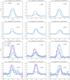 |
Fig. 10 Comparison between the best-fit modeled spectra (in blue lines) and observed CH3OH lines (gray histograms) at the dust peak (upper two rows) and CH3OH peak (lower two rows). In the lowest panels, the spectra at the c-C3Hշ peak and HNCO peak are also shown for comparison. The optical depth at the line center derived from the model is indicated in each subplot. |
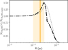 |
Fig. 11 Comparison between the radial profile of the CH3OH column density, |


4.2 Local density enhancement at methanol peak
The one-component non-LTE models of CH3OH lines at the three molecular peaks suggest gas densities well above 105 cm−3. With LOC models, we find that only by increasing the gas densities locally can the observed line intensities and ratios be well reproduced. This was already suggested by the result of RADEX models: even with the depletion of CH3OH in the core center, such that the line emission does not sample the densest gas, beam-averaged gas densities (from the one-component non-LTE models) are still comparable with those estimated from the radial density profile of L1544 without incomplete sampling. Previous works on a variety of molecular lines and dust continuum toward L1544 have consistently suggested that the overall density structure of the core follows a BE sphere (Keto & Caselli 2010; Keto et al. 2015; Redaelli et al. 2019; Koumpia et al. 2020). The density enhancement seen by CH3OH suggests that the density structures can deviate from the average BE density profile locally, showing a clumpier distribution.
Punanova et al. (2018) mapped the CH3OH peak with the NOEMA observations and found that the centroid velocity and velocity dispersion increase toward the dust peak, which is indicative of accretion or the interaction of two filaments. The large-scale cloud that L1544 is embedded in has two perpendicular structures (André et al. 2010; Spezzano et al. 2016) that seem to meet at the CH3OH peak (see also Tafalla et al. 1998) and may cause a weak collision shock. In Sect. 3.2.1, using the NOEMA observations, we obtained the n(H2) map using the ratio of the 20−10 and 2−1−1−1 lines of E CH3OH. Within the uncertainties, the n(H2) map shows that the regions of largest densities form a ring-like structure that surrounds the central core region of L1544 and do not coincide with the  peak (Fig. 5). Overall, the morphology of the density enhancements around the CH3OH peak of L1544 appears rather distributed and spatially extended, without clear and concentrated centers. Since the density enhancements are also associated with the highest velocity in the southwest direction (~7.3 kms−1; see Fig. 6 of Punanova et al. 2018), the picture seems to favor a mild accretion flow that accelerates toward the direction of the core center, causing enhanced gas densities. At this position, the merging of large-scale cloud structures may also play a role in delivering the gas material, the extended mapping of which would reveal the kinematic features.
The density enhancement in the modified density models is a factor of 5–10 larger than the densities at same radii predicted by the BE sphere model. We now consider whether it could be a result of shock conditions. In the presence of shocks (either due to accretion or merging clouds), the density enhancement across an interface is related to variations of fluid velocity (Draine & McKee 1993), where ρ0υ0 = ρ1 υ1. With an additional condition of energy conservation in the case of adiabatic shocks, it holds that  in which γ is the adiabatic index and M0 the Mach number. The maximum density contrast for diatomic gas (γ = 7/5) is therefore 6. On the other hand, for isothermal shocks,
  , meaning that the density enhancement can be arbitrarily large. Taking the temperature of 10 K at 0.02 pc with a sound speed of 0.2 km s−1, for a density enhancement of a factor of 5–10, the Mach number should be ≲4.5 in the adiabatic case and ~2.2–3 in the isothermal case. The velocity gradient surrounding the CH3OH peak appears largest in the south of the map (close to the dust peak), reaching ~12 kms−1 pc−1 (Punanova et al. 2018). Over a distance of 0.025 pc, this corresponds to a velocity difference of ~0.3 km s−1 assuming it varies uniformly. Considering the projection effect, a real velocity variation of -0.6-1 km s−1, which would reach the Mach number required for the density enhancement we resolved here, is possible.
Toward the HNCO and c-C3H2 peaks, the density enhancement is less spatially extended than that at the CH3OH peak. The density enhancements at 0.02 pc thus appear asymmetric, based on measurements of these three directions of molecular peaks. A high-angular-resolution and sensitivity mapping of CH3OH lines is desired given the preferential distribution of CH3OH, since at the HNCO and c-C3H2 peaks the higher K components of the CH3OH line might be too weak to yield more robust determinations of n(H2).
The localized density enhancement likely only occupies a small volume of the core, meaning the overall density structure is likely well described by a BE sphere. The nonuniform distribution of dense gas surrounding the central region of dense cores may be related to the highly variable accretion rates associated with the formation of low-mass protostars at smaller scales, a common phenomenon during the protostar evolution (Audard et al. 2014). Based on the association of the density enhancement with the gas velocity gradient, we speculate that the clumpy gas can be formed in situ due to non-steady gravitational inflow and that it intercepts the overall smooth BE sphere of the bulk gas. Numerical simulations also show that clumpy gas around an early-stage core can initially originate due to a disturbance of turbulence (Matsumoto & Hanawa 2011; Lewis & Bate 2018) and that this gas tends to be smoothed out inside a gravitationally collapsing core. Whether the over-densities will be enhanced due to self-gravity or torn apart by tidal forces depends, essentially, on their mass scale and “thickness” with respect to that of the enclosed gas (i.e., the gas component interior to the over-density; Coughlin 2017). The eventual infall of the over-densities onto the central point mass can cause a temporal increase in the accretion rate. In any case, a smoothly decreasing BE sphere is not sufficient to describe the localized gas behavior inside the pre-stellar core nor the influence from a large-scale cloud environment (Pineda et al. 2022). The questions of how the underlying over-densities of a pre-stellar core form initially and how they evolve and eventually affect star formation remain to be systematically investigated in future observational and theoretical studies.
5 Conclusions
Using multiline observations of CH3OH, c-C3Hշ, and HNCO toward the dust peak and the three respective molecular peaks of L1544, we probed different gas density layers. With full radiative transfer modeling implemented with radial abundance profiles, we revisited the density structure of L1544 and gauged the current chemical models. The main conclusions are:
With one-component non-LTE models, we find that at the dust peak and the three molecular peaks at a 0.02 pc radius, CH3OH lines trace gas densities of 0(H2) > 105 cm−3, while emission lines of c-C3H2 and HNCO mainly originate from the outer, less dense gas layers of several 104 cm−3. Even with the incomplete sampling of the inner core region due to CH3OH depletion, the n(H2) traced by CH3OH lines are close to the beam-averaged gas densities at the dust peak and molecular peaks estimated from the previously well-established radial density profiles of L1544;
The BE sphere density structure of L1544, coupled with the radial abundance profiles of HNCO and c-C3H2 predicted from chemical models (Sipilä et al. 2016), can produce spectra consistent with the observed line intensities at the dust peak and respective molecular peaks. The abundance profiles only require a factor of 3–5 increment to achieve better agreement with the observed lines at the molecular peaks, within the uncertainty of the chemical models;
At the CH3OH peak, the gas density enhancements seen from the n(H2) map derived from the CH3OH 2K−1K lines at ~700 au angular resolution are offset from the
 peak and appear to be a ring-like clumpy structure surrounding the core center;
CH3OH lines at the dust peak and CH3OH peak can only be well reproduced with a modified radial density model that includes a local density enhancement encompassing the ~0.02 pc radius of the core in addition to a scaled-down (by a factor of 5–10) radial abundance profile of CH3OH based on chemical models (Vasyunin et al. 2017). Such a local density enhancement may be caused by slow shocks induced by asymmetric and dynamic accretion flows and may be related to the kinematics of the large-scale cloud where L1544 is embedded.
In this work, we have demonstrated that multiline observations of molecules that exhibit significant chemical differentiation can be adopted as useful tools to probe the underlying physical properties in pre-stellar cores. CH3OH lines, in particular, may be well suited to probe the dense gas component of pre-stellar cores. Our results again suggest that a symmetric and smooth density profile can be oversimplified to describe the structure of pre-stellar cores, which may exhibit over-densities locally that deviate from the overall BE sphere structure. A more extended and higher-angular-resolution CH3OH mapping toward L1544 is desirable to pinpoint the origin of the over-densities and shed light on the physical and chemical processes that are causing the enhancement of CH3OH in the gas phase, which could be related to the ongoing accretion flows into the pre-stellar core.
Acknowledgements
The authors acknowledge the financial support of the Max Planck Society. The authors wish to thank the anonymous referee and the editor for insightful comments. YL thanks Mika Juvela for helpful discussions. AV acknowledges support from the Russian Ministry of Science and Higher Education via the State Assignment Contract FEUZ-2020-0038. This work is based on observations carried out under project number 101-20 with the IRAM 30 m telescope IRAM is supported by INSU/CNRS (France), MPG (Germany) and IGN (Spain).
Appendix A Posterior distribution of the MCMC RADEX models
 |
Fig. A.1 Posterior distribution of parameters Tkin, lοg10(n(Η2)), and log10(Nmol/ΔV) based on modeling CH3OH (E-tyρe) lines at the dust peak (upper left), the CH3OH peak (upper right), the HNCO peak (lower left), and the c-C3H2 peak (lower right). All three parameters are kept free. In these plots and the plots in Figs. A.2–A.4, the vertical dashed lines in the one-dimensional histograms show the quantiles of 10%, 25%, 50%, 75%, and 90%. The contour levels in the two-dimensional histograms indicate Ο.5σ 1σ 1.5σ and 2σ respectively. |
 |
Fig. A.2 Posterior distribution of Tkin lοg10(n(Η2)), and log10(Nmol/ΔV) based on modeling c-C3H2 lines at the dust peak. All parameters are kept free. |
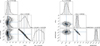 |
Fig. A.3 Posterior distribution of Tkin, log10(n(Η2)), and log10(Nmol/ΔV) based on modeling c-C3H2 lines at the o-C3H2 peak. Left: All parameters kept free. Right: Tkin following N(μ=10 Κ, σ =5 Κ) with the other two parameters kept free. |
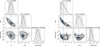 |
Fig. A.4 Posterior distribution of Tkin, log10(n(Η2)), and log10(Nmol/ΔV) based on modeling HNCO lines at the dust peak and the HNCO peak. Tkin follows Ν(μ=10 Κ, σ=5 Κ) at the dust peak and at the HNCO peak, and the other two parameters are kept free. |
Appendix B Comparison between modeled spectra from LOC and the observational data
The modeled spectra with LOC for abundance profiles from different epochs (Sect. 3.2.2) are shown here. The model spectral cubes were convolved with the respective beam at each frequency, and the spectra were extracted at the position of either the dust peak or the molecular peaks for comparison with observed lines.
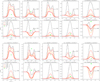 |
Fig. B.1 Comparison between modeled spectra and observed CH3OH lines, with radial abundance profiles following Vasyunin et al. (2017) for different epochs between 0.1 and 1 Myr. The spectra at the dust peak and at the CH3OH peak are shown in the upper panel and the lower panel, respectively. The optical depth for each modeled line of the 0.4 Myr epoch abundance profile is indicated in each subplot. In the title of each subplot, the quantum numbers, upper energy levels, and the critical density are shown. |
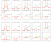 |
Fig. B.2 Same as Fig. B.1, but with adjusted radial abundance profiles (based on the original abundance profiles in Vasyunin et al. (2017). The abundance profile is scaled down by a constant factor of 5. |
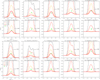 |
Fig. B.3 Same as Fig. B.1, but with adjusted radial abundance profiles (based on the original abundance profiles in Vasyunin et al. 2017) and with gas density profiles adopted for the models. The abundance profile is scaled down by a constant factor of 10, and the gas density profile follows the modified radial density profile, as in Fig. 9. |
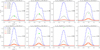 |
Fig. B.4 Comparison between modeled spectra and observed c-C3H2 lines, with radial abundance profiles following Sipilä et al. (2015) for different epochs between 0.1 and 1 Myr. The spectra at the dust peak and at the c-C3H2 peak are shown in the upper panel and lower panels, respectively. The optical depth for each modeled line of the 0.13 Myr epoch abundance profile is indicated in each subplot. |
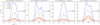 |
Fig. B.5 Same as the lower panel of Fig. B.4, but with adjusted radial abundance profiles (based on the original abundance profiles in Sipilä et al. 2015). The abundance profile is scaled up by a constant factor of 3. |
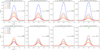 |
Fig. B.6 Comparison between modeled spectra and observed HNCO lines, with radial abundance profiles following Sipilä et al. (2015) for different epochs between 0.1 and 1 Myr. The spectra at the dust peak and at the HNCO peak are shown in the upper panel and the lower panel, respectively. The optical depth for each modeled line of the 0.1 Myr epoch abundance profile is indicated in each subplot. |
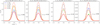 |
Fig. B.7 Same as Fig. B.6, but with adjusted radial abundance profiles (based on the original abundance profiles in Sipilä et al. 2015). The abundance profile is scaled up by a constant factor of 5. |
References
- Agúndez, M., Marcelino, N., Cernicharo, J., Roueff, E., & Tafalla, M. 2019, A&A, 625, A147 [Google Scholar]
- André, P., Men’shchikov, A., Bontemps, S., et al. 2010, A&A, 518, A102 [Google Scholar]
- Audard, M., Ábrahám, P., Dunham, M. M., et al. 2014, in Protostars and Planets VI, eds. H. Beuther, R. S. Klessen, C. P. Dullemond, & T. Henning, 387 [Google Scholar]
- Avery, L. W. 1987, in Astrochemistry, 120, eds. M. S. Vardya, & S. P. Tarafdar, 187 [NASA ADS] [CrossRef] [Google Scholar]
- Bacmann, A., & Faure, A. 2016, A&A, 587, A130 [NASA ADS] [CrossRef] [EDP Sciences] [Google Scholar]
- Ben Khalifa, M., Sahnoun, E., Spezzano, S., et al. 2019, Proc. Int. Astron. Union, 15, 148 [CrossRef] [Google Scholar]
- Bergin, E. A., & Tafalla, M. 2007, ARA&A, 45, 339 [Google Scholar]
- Bizzocchi, L., Caselli, P., Spezzano, S., & Leonardo, E. 2014, A&A, 569, A27 [NASA ADS] [CrossRef] [EDP Sciences] [Google Scholar]
- Broderick, A. E., & Keto, E. 2010, ApJ, 721, 493 [NASA ADS] [CrossRef] [Google Scholar]
- Caselli, P., & Ceccarelli, C. 2012, A&Ar, 20, 56 [NASA ADS] [CrossRef] [Google Scholar]
- Caselli, P., Pineda, J. E., Zhao, B., et al. 2019, ApJ, 874, 89 [NASA ADS] [CrossRef] [Google Scholar]
- Caselli, P., Walmsley, C. M., Zucconi, A., et al. 2002a, ApJ, 565, 331 [NASA ADS] [CrossRef] [Google Scholar]
- Caselli, P., Walmsley, C. M., Zucconi, A., et al. 2002b, ApJ, 565, 344 [Google Scholar]
- Caselli, P., Pineda, J. E., Sipilä, O., et al. 2022, ApJ, 929, 13 [NASA ADS] [CrossRef] [Google Scholar]
- Ceccarelli, C., Caselli, P., Herbst, E., Tielens, A. G. G. M., & Caux, E. 2007, in Protostars and Planets V, eds. B. Reipurth, D. Jewitt, & K. Keil, 47 [Google Scholar]
- Chacón-Tanarro, A., Caselli, P., Bizzocchi, L., et al. 2019, A&A, 622, A141 [Google Scholar]
- Chantzos, J., Spezzano, S., Caselli, P., et al. 2018, ApJ, 863, 126 [CrossRef] [Google Scholar]
- Coughlin, E. R. 2017, ApJ, 835, 40 [NASA ADS] [CrossRef] [Google Scholar]
- Cox, P., Walmsley, C. M., & Guesten, R. 1989, A&A, 209, 382 [NASA ADS] [Google Scholar]
- Crapsi, A., Caselli, P., Walmsley, M. C., & Tafalla, M. 2007, A&A, 470, 221 [NASA ADS] [CrossRef] [EDP Sciences] [Google Scholar]
- di Francesco, J., Evans, N. J. I., Caselli, P., et al. 2007, in Protostars and Planets V, eds. B. Reipurth, D. Jewitt, & K. Keil, 17 [Google Scholar]
- Draine, B. T., & McKee, C. F. 1993, ARA&A, 31, 373 [NASA ADS] [CrossRef] [Google Scholar]
- Foreman-Mackey, D., Hogg, D. W., Lang, D., & Goodman, J. 2013, PASP, 125, 306 [Google Scholar]
- Goodwin, S. P., Whitworth, A. P., & Ward-Thompson, D. 2004, A&A, 423, 169 [NASA ADS] [CrossRef] [EDP Sciences] [Google Scholar]
- Harju, J., Pineda, J. E., Vasyunin, A. I., et al. 2020, ApJ, 895, 101 [NASA ADS] [CrossRef] [Google Scholar]
- Hocking, W. H., Gerry, M. C. L., & Winnewisser, G. 1975, Can. J. Phys., 53, 1869 [NASA ADS] [CrossRef] [Google Scholar]
- Jiménez-Serra, I., Vasyunin, A. I., Caselli, P., et al. 2016, ApJ, 830, L6 [Google Scholar]
- Jørgensen, J. K., Belloche, A., & Garrod, R. T. 2020, ARA&A, 58, 727 [Google Scholar]
- Juvela, M. 2020, A&A, 644, A151 [NASA ADS] [CrossRef] [EDP Sciences] [Google Scholar]
- Kalenskii, S. V., & Kurtz, S. 2016, Astron. Rep., 60, 702 [NASA ADS] [CrossRef] [Google Scholar]
- Keto, E., & Caselli, P. 2010, MNRAS, 402, 1625 [Google Scholar]
- Keto, E., & Field, G. 2005, ApJ, 635, 1151 [NASA ADS] [CrossRef] [Google Scholar]
- Keto, E., Rawlings, J., & Caselli, P. 2014, MNRAS, 440, 2616 [NASA ADS] [CrossRef] [Google Scholar]
- Keto, E., Caselli, P., & Rawlings, J. 2015, MNRAS, 446, 3731 [NASA ADS] [CrossRef] [Google Scholar]
- Koumpia, E., Evans, L., Di Francesco, J., van der Tak, F. F. S., & Oudmaijer, R. D. 2020, A&A, 643, A61 [NASA ADS] [CrossRef] [EDP Sciences] [Google Scholar]
- Lees, R. M. 1973, ApJ, 184, 763 [Google Scholar]
- Lewis, B. T., & Bate, M. R. 2018, MNRAS, 477, 4241 [CrossRef] [Google Scholar]
- Lin, Y., Wyrowski, F., Liu, H. B., et al. 2022, A&A, 658, A128 [NASA ADS] [CrossRef] [EDP Sciences] [Google Scholar]
- Mac Low, M.-M., & Klessen, R. S. 2004, Rev. Mod. Phys., 76, 125 [Google Scholar]
- Matsumoto, T., & Hanawa, T. 2011, ApJ, 728, 47 [NASA ADS] [CrossRef] [Google Scholar]
- Minissale, M., Dulieu, F., Cazaux, S., & Hocuk, S. 2016, A&A, 585, A24 [NASA ADS] [CrossRef] [EDP Sciences] [Google Scholar]
- Myers, P. C., Mardones, D., Tafalla, M., Williams, J. P., & Wilner, D. J. 1996, ApJ, 465, L133 [NASA ADS] [CrossRef] [Google Scholar]
- Nakano, T. 1998, ApJ, 494, 587 [NASA ADS] [CrossRef] [Google Scholar]
- Navarro-Almaida, D., Fuente, A., Majumdar, L., et al. 2021, A&A, 653, A15 [NASA ADS] [CrossRef] [EDP Sciences] [Google Scholar]
- Offner, S. S. R., Kratter, K. M., Matzner, C. D., Krumholz, M. R., & Klein, R. I. 2010, ApJ, 725, 1485 [Google Scholar]
- Ohashi, S., Sanhueza, P., Sakai, N., et al. 2018, ApJ, 856, 147 [NASA ADS] [CrossRef] [Google Scholar]
- Pineda, J. E., Arzoumanian, D., André, P., et al. 2022, in Protostars and Planets VII, in press [arXiv:2205.03935] [Google Scholar]
- Pratap, P., Dickens, J. E., Snell, R. L., et al. 1997, ApJ, 486, 862 [Google Scholar]
- Punanova, A., Caselli, P., Feng, S., et al. 2018, ApJ, 855, 112 [NASA ADS] [CrossRef] [Google Scholar]
- Punanova, A., Vasyunin, A., Caselli, P., et al. 2022, ApJ, 927, 213 [CrossRef] [Google Scholar]
- Rabli, D., & Flower, D. R. 2010, MNRAS, 406, 95 [Google Scholar]
- Redaelli, E., Bizzocchi, L., Caselli, P., et al. 2019, A&A, 629, A15 [NASA ADS] [CrossRef] [EDP Sciences] [Google Scholar]
- Rybicki, G. B., & Hummer, D. G. 1991, A&A, 245, 171 [NASA ADS] [Google Scholar]
- Sahnoun, E., Wiesenfeld, L., Hammami, K., & Jaidane, N. 2018, J. Phys. Chem. A, 122, 3004 [NASA ADS] [CrossRef] [Google Scholar]
- Sahu, D., Liu, S.-Y., Liu, T., et al. 2021, ApJ, 907, L15 [NASA ADS] [CrossRef] [Google Scholar]
- Semenov, D., Hersant, F., Wakelam, V., et al. 2010, A&A, 522, A42 [NASA ADS] [CrossRef] [EDP Sciences] [Google Scholar]
- Shirley, Y. L. 2015, PASP, 127, 299 [Google Scholar]
- Sipilä, O., Caselli, P., & Harju, J. 2015, A&A, 578, A55 [Google Scholar]
- Sipilä, O., Spezzano, S., & Caselli, P. 2016, A&A, 591, L1 [NASA ADS] [CrossRef] [EDP Sciences] [Google Scholar]
- Soma, T., Sakai, N., Watanabe, Y., & Yamamoto, S. 2015, ApJ, 802, 74 [NASA ADS] [CrossRef] [Google Scholar]
- Spezzano, S., Bizzocchi, L., Caselli, P., Harju, J., & Brünken, S. 2016, A&A, 592, L11 [NASA ADS] [CrossRef] [EDP Sciences] [Google Scholar]
- Spezzano, S., Caselli, P., Bizzocchi, L., Giuliano, B. M., & Lattanzi, V. 2017, A&A, 606, A82 [NASA ADS] [CrossRef] [EDP Sciences] [Google Scholar]
- Spezzano, S., Caselli, P., Pineda, J. E., et al. 2020, A&A, 643, A60 [NASA ADS] [CrossRef] [EDP Sciences] [Google Scholar]
- Suzuki, H., Yamamoto, S., Ohishi, M., et al. 1992, ApJ, 392, 551 [Google Scholar]
- Tafalla, M., Mardones, D., Myers, P. C., et al. 1998, ApJ, 504, 900 [NASA ADS] [CrossRef] [Google Scholar]
- Tafalla, M., Santiago-García, J., Myers, P. C., et al. 2006, A&A, 455, 577 [NASA ADS] [CrossRef] [EDP Sciences] [Google Scholar]
- Takakuwa, S., Kawaguchi, K., Mikami, H., & Saito, M. 2001, PASJ, 53, 251 [NASA ADS] [CrossRef] [Google Scholar]
- Tatematsu, K., Liu, T., Kim, G., et al. 2020, ApJ, 895, 119 [NASA ADS] [CrossRef] [Google Scholar]
- Tokuda, K., Fujishiro, K., Tachihara, K., et al. 2020, ApJ, 899, 10 [NASA ADS] [CrossRef] [Google Scholar]
- van der Tak, F. F. S., Black, J. H., Schöier, F. L., Jansen, D. J., & van Dishoeck, E. F. 2007, A&A, 468, 627 [NASA ADS] [CrossRef] [EDP Sciences] [Google Scholar]
- van Dishoeck, E. F., & Blake, G. A. 1998, ARA&A, 36, 317 [Google Scholar]
- Vastel, C., Ceccarelli, C., Lefloch, B., & Bachiller, R. 2014, ApJ, 795, L2 [NASA ADS] [CrossRef] [Google Scholar]
- Vasyunin, A. I., Caselli, P., Dulieu, F., & Jiménez-Serra, I. 2017, ApJ, 842, 33 [Google Scholar]
- Vrtilek, J. M., Gottlieb, C. A., & Thaddeus, P. 1987, ApJ, 314, 716 [CrossRef] [Google Scholar]
- Wakelam, V., & Herbst, E. 2008, ApJ, 680, 371 [NASA ADS] [CrossRef] [Google Scholar]
- Xu, L.-H., Fisher, J., Lees, R. M., et al. 2008, J. Mol. Spectrosc., 251, 305 [NASA ADS] [CrossRef] [Google Scholar]
A detailed description of the method can be found in the emcee documentation.
All Tables
All Figures
|
Fig. 1 Integrated intensity maps (in color scale) of CH3OH-E 2−1,2−1−1,1, c-C3H2 З2,2−31,3, and HNCO 40,4−30,з (from left to right) observed by the IRAM 30 m telescope, showing the different locations of the molecular peaks (Table 2, Spezzano et al. 2017). The contour levels (in orange) show 3.2 × 10²¹, 4.3 × 10²¹, 5.9 × 10²¹, 8.1 × 10²¹, 1.1 × 10²², 1.5 × 10²², and 2.1 × 1022 cm−2 of the molecular hydrogen column density ( |
| In the text | |
|
Fig. 2 Observed CH3OH spectra at the dust peak and at the molecular peaks. The spectra are arranged in order of increasing frequency. Vertical dotted lines indicate VLSR = 7.19 kms−1. |
| In the text | |
|
Fig. 3 Observed c-C3H2 and HNCO spectra at the dust peak and at the molecular peaks. The spectra are arranged in order of increasing frequency. Vertical dotted lines indicate VLSR = 7.19 kms−1. |
| In the text | |
|
Fig. 4 Derived CH3OH column density map and hydrogen volume density from RADEX modeling. The contours (in gray) are NH2 levels, the same as those in Fig. 1. The markers in blue represent the dust peak (diamond), molecular emission peaks of CH3OH (three-branched triangle), HNCO (upward pointing triangle), and c-C3H2 (plus sign). |
| In the text | |
|
Fig. 5
|
| In the text | |
|
Fig. 6 Radial profiles of gas density, temperature, and infall velocity. The light orange shaded region indicates the beam area with which the molecular peaks are identified, centered at an offset of 0.02pc (with respect to the dust peak), shown by a vertical orange line. |
| In the text | |
|
Fig. 7 Radial abundance profiles from chemical models. Left and middle panels: radial abundance profiles of c-C3H2 and HNCO for selected epochs, predicted by chemical modeling in Sipilä et al. (2015). Right panel: radial abundance profiles of CH3OH, predicted by chemical modeling in Vasyunin et al. (2017). |
| In the text | |
|
Fig. 8 Comparison between T(r) (gray line) and the radial profile of Tex of all CH3OH lines from the best-fit model with modified radial density profiles (left) and original density profiles (right). The best-fit abundance profiles are at 0.8 Myr from Vasyunin et al. (2017), which were scaled down by a factor of 5 and 10 in the left and right panels (of model A and model B), respectively. The cosmic microwave background temperature of 2.73 Κ is also indicated (black horizontal line). The four J0−J−1 lines are shown with thicker line widths. |
| In the text | |
|
Fig. 9 Modified radial density profile (purple) in comparison with the original and beam-convolved radial density profiles (green) of L1544 established in Keto & Caselli (2010) (indicated by KC10 in the legend). Gray crosses indicate the gas density values measured from the n(Η2) map, as in Fig. 5. The light orange shaded region indicates the beam area with which the molecular peaks are identified, centered at an offset of 0.02 pc (with respect to the dust peak) and shown by a vertical orange line. |
| In the text | |
|
Fig. 10 Comparison between the best-fit modeled spectra (in blue lines) and observed CH3OH lines (gray histograms) at the dust peak (upper two rows) and CH3OH peak (lower two rows). In the lowest panels, the spectra at the c-C3Hշ peak and HNCO peak are also shown for comparison. The optical depth at the line center derived from the model is indicated in each subplot. |
| In the text | |
|
Fig. 11 Comparison between the radial profile of the CH3OH column density, |
| In the text | |
|
Fig. A.1 Posterior distribution of parameters Tkin, lοg10(n(Η2)), and log10(Nmol/ΔV) based on modeling CH3OH (E-tyρe) lines at the dust peak (upper left), the CH3OH peak (upper right), the HNCO peak (lower left), and the c-C3H2 peak (lower right). All three parameters are kept free. In these plots and the plots in Figs. A.2–A.4, the vertical dashed lines in the one-dimensional histograms show the quantiles of 10%, 25%, 50%, 75%, and 90%. The contour levels in the two-dimensional histograms indicate Ο.5σ 1σ 1.5σ and 2σ respectively. |
| In the text | |
|
Fig. A.2 Posterior distribution of Tkin lοg10(n(Η2)), and log10(Nmol/ΔV) based on modeling c-C3H2 lines at the dust peak. All parameters are kept free. |
| In the text | |
|
Fig. A.3 Posterior distribution of Tkin, log10(n(Η2)), and log10(Nmol/ΔV) based on modeling c-C3H2 lines at the o-C3H2 peak. Left: All parameters kept free. Right: Tkin following N(μ=10 Κ, σ =5 Κ) with the other two parameters kept free. |
| In the text | |
|
Fig. A.4 Posterior distribution of Tkin, log10(n(Η2)), and log10(Nmol/ΔV) based on modeling HNCO lines at the dust peak and the HNCO peak. Tkin follows Ν(μ=10 Κ, σ=5 Κ) at the dust peak and at the HNCO peak, and the other two parameters are kept free. |
| In the text | |
|
Fig. B.1 Comparison between modeled spectra and observed CH3OH lines, with radial abundance profiles following Vasyunin et al. (2017) for different epochs between 0.1 and 1 Myr. The spectra at the dust peak and at the CH3OH peak are shown in the upper panel and the lower panel, respectively. The optical depth for each modeled line of the 0.4 Myr epoch abundance profile is indicated in each subplot. In the title of each subplot, the quantum numbers, upper energy levels, and the critical density are shown. |
| In the text | |
|
Fig. B.2 Same as Fig. B.1, but with adjusted radial abundance profiles (based on the original abundance profiles in Vasyunin et al. (2017). The abundance profile is scaled down by a constant factor of 5. |
| In the text | |
|
Fig. B.3 Same as Fig. B.1, but with adjusted radial abundance profiles (based on the original abundance profiles in Vasyunin et al. 2017) and with gas density profiles adopted for the models. The abundance profile is scaled down by a constant factor of 10, and the gas density profile follows the modified radial density profile, as in Fig. 9. |
| In the text | |
|
Fig. B.4 Comparison between modeled spectra and observed c-C3H2 lines, with radial abundance profiles following Sipilä et al. (2015) for different epochs between 0.1 and 1 Myr. The spectra at the dust peak and at the c-C3H2 peak are shown in the upper panel and lower panels, respectively. The optical depth for each modeled line of the 0.13 Myr epoch abundance profile is indicated in each subplot. |
| In the text | |
|
Fig. B.5 Same as the lower panel of Fig. B.4, but with adjusted radial abundance profiles (based on the original abundance profiles in Sipilä et al. 2015). The abundance profile is scaled up by a constant factor of 3. |
| In the text | |
|
Fig. B.6 Comparison between modeled spectra and observed HNCO lines, with radial abundance profiles following Sipilä et al. (2015) for different epochs between 0.1 and 1 Myr. The spectra at the dust peak and at the HNCO peak are shown in the upper panel and the lower panel, respectively. The optical depth for each modeled line of the 0.1 Myr epoch abundance profile is indicated in each subplot. |
| In the text | |
|
Fig. B.7 Same as Fig. B.6, but with adjusted radial abundance profiles (based on the original abundance profiles in Sipilä et al. 2015). The abundance profile is scaled up by a constant factor of 5. |
| In the text | |
Current usage metrics show cumulative count of Article Views (full-text article views including HTML views, PDF and ePub downloads, according to the available data) and Abstracts Views on Vision4Press platform.
Data correspond to usage on the plateform after 2015. The current usage metrics is available 48-96 hours after online publication and is updated daily on week days.
Initial download of the metrics may take a while.