| Issue |
A&A
Volume 620, December 2018
|
|
|---|---|---|
| Article Number | A169 | |
| Number of page(s) | 25 | |
| Section | Interstellar and circumstellar matter | |
| DOI | https://doi.org/10.1051/0004-6361/201833445 | |
| Published online | 14 December 2018 | |
An imaging spectroscopic survey of the planetary nebula NGC 7009 with MUSE★,★★
1
European Southern Observatory, Karl-Schwarzschild Strasse 2,
85748 Garching,
Germany
e-mail: This email address is being protected from spambots. You need JavaScript enabled to view it.
2
Instituto de Astrofísica de Canarias (IAC),
38025 La Laguna,
Tenerife, Spain
3
Departamento de Astrofísica, Universidad de La Laguna,
38206 La Laguna,
Tenerife, Spain
4
Department of Physics and Astronomy, University College London,
Gower Street,
London WC1E 6BT, UK
5
Department of Physics and Astronomy, University of Denver,
2112 E. Wesley Ave.,
Denver,
CO,
80210, USA
6
Jodrell Bank Centre for Astrophysics, Alan Turing Building, University of Manchester, Manchester M13 9PL, UK
7
Laboratory for Space Research, University of Hong Kong,
Pokfulam Road,
Hong Kong
8
Instituto de Astronomía, Universidad Católica del Norte,
Av. Angamos 0610,
Antofagasta, Chile
9
Institut für Astro- und Teilchenphysik, Leopold–Franzens Universität Innsbruck,
Technikerstrasse 25,
6020 Innsbruck, Austria
10
Leiden Observatory, University of Leiden,
Leiden, the Netherlands
11
Oberkasseler Straße 130,
40545 Düsseldorf,
Germany
12
Okayama Observatory, Kyoto University Honjo, Kamogata,
Asakuchi,
Okayama,
719-0232, Japan
Received:
17
May
2018
Accepted:
14
September
2018
Abstract
Aims. The spatial structure of the emission lines and continuum over the 50″ extent of the nearby, O-rich, PN NGC 7009 (Saturn Nebula) have been observed with the MUSE integral field spectrograph on the ESO Very Large Telescope. This study concentrates on maps of line emission and their interpretation in terms of physical conditions.
Methods. MUSE Science Verification data, in <0.6″ seeing, have been reduced and analysed as maps of emission lines and continuum over the wavelength range 4750–9350 Å. The dust extinction, the electron densities and temperatures of various phases of the ionized gas, abundances of species from low to high ionization and some total abundances are determined using standard techniques.
Results. Emission line maps over the bright shells are presented, from neutral to the highest ionization available (He II and [Mn V]). For collisionally excited lines (CELs), maps of electron temperature (Te from [N II] and [S III]) and density (Ne from [S II] and [Cl III]) are available and for optical recombination lines (ORLs) temperature (from the Paschen jump and ratio of He I lines) and density (from high Paschen lines). These estimates are compared: for the first time, maps of the differences in CEL and ORL Te’s have been derived, and correspondingly a map of t2 between a CEL and ORL temperature, showing considerable detail. Total abundances of only He and O were formed, the latter using three ionization correction factors. However, the map of He/H is not flat, departing by ~2% from a constant value, with remnants corresponding to ionization structures. An integrated spectrum over an area of 2340 arcsec2 was also formed and compared to 1D photoionization models.
Conclusions. The spatial variation of a range of nebular parameters illustrates the complexity of the ionized media in NGC 7009. These MUSE data are very rich with detections of hundreds of lines over areas of hundreds of arcsec2 and follow-on studies are outlined.
Key words: planetary nebulae: individual: NGC 7009 / stars: AGB and post-AGB / ISM: abundances / dust, extinction / atomic processes
Based on observations collected at the European Organisation for Astronomical Research in the Southern Hemisphere, Chile in Science Verification (SV) observing proposal 60.A-9347(A).
FITS files of all the individual maps are only available at the CDS via anonymous ftp to cdsarc.u-strasbg.fr (130.79.128.5) or via http://cdsarc.u-strasbg.fr/viz-bin/qcat?J/A+A/620/A169
© ESO 2018
1 Introduction
Planetary nebulae (PNe) provide self-contained laboratories of a wide range of low density ionization conditions and thus form a corner-stone of studies of the interstellar medium in general, from the diffuse interstellar medium, to H II and He II regions surrounding hot stars of all evolutionary stages to the highest density regions in stellar coronae and active galactic nuclei. However, this advantage also proves a challenge, as the range of ionization conditions occur within a single object and all but a few nearby Galactic PNe are compact or slightly extended targets. Observation with a small aperture or slit is bound to sample a range of conditions, framing high and low ionization, low to higher density (typical range 101–106 cm−3), low to moderate electron temperature (range a few × 103 to ~25 000 K), including X-ray emitting gas with temperatures to ~106 K (for example Guerrero et al. 2000, and the results from the ChanPlaNS consortium: Kastner et al. 2012; Freeman et al. 2014; Montez et al. 2015). The resulting spectrum contains a summation of these conditions, the exact mixture depending on the nebular morphology, the temperature of the central star and the velocity and mass loss rate of its stellar wind, the age of the PN (younger PN generally being of higher density), the homogeneity of the circumstellar gas, the metal abundance and the content of dust. Spectroscopy with 2D coverage leads to increased understanding of the nebular structure and the role of the local physical conditions on the emitted spectrum, since PNe generally show a gradient in ionization from close to the central star to lower values in the outer regions.
Slit spectroscopy has until recently been the primary tool for PN spectroscopy, where the typical slit can sample the central higher ionization zone to the low ionization or neutral outer regions, depending on whether the nebula is density or ionization bounded. For moderately extended PNe (sizes 10–100’s″), the selection of the slit is all-important. Often the placement is made based on shape, extension matching the slit, features of interest such as knots, filaments/jets, bipolar axis, etc, which in terms of sampling the widest possible range of conditions may not be representative. A good example is the seminal study of NGC 7009 by X.-H. Liu and X. Fang and co-workers (Liu & Danziger 1993; Liu et al. 1995b; Fang & Liu 2011, 2013), which has presented the deepest and most comprehensive optical (3000–10 000 Å) spectroscopy to date. Their study is primarily based on spectra derived from a single long slit aligned along the major axis and including the horns (ansae) and the outer low ionization knots. To step from this particular spatial sampling of the conditions in the ionized and neutral gas to a comprehensive description of the whole nebula is clearly an extrapolation of unknown magnitude, unless a wider range of conditions are sampled (in this case as next obvious choice a slit along the minor axis). In addition comparison of nebular properties based on single slit spectra between nebulae may not be strictly valid since various differing choices may have been applied in choosing the slit position and orientation.
Studies devoted to imaging of selected emission lines, chosen to sample the range of conditions in typical PNe, have been undertaken, often in co-ordination with slit spectroscopy, the latter targeting regions with particular conditions. Typical examples, which have focussed on NGC 7009, are Bohigas et al. (1994) and Lame & Pogge (1996). With imaging in bright permitted and forbidden lines from He II to [O I], a wide span of ionization conditions can be sampled and narrow filters tunedto line pairs sensitive to electron density and temperature provide maps of the diagnostics, such as [S II]6716.4 and 6730.8 Å, and [O III]5006.9 and 4363.2 Å. Of course, these images have to be corrected for the continuum collected within the filter bandwidth, whose origin is bound-free, free-free from ionized H and He and the H+ and He++ two photon emission, as well as direct or scattered starlight from the central star (or any field stars along the line of sight). In the infrared, Persi et al. (1999) used the circular variable filter (CVF) on ISOCAM for wavelength stepped monochromatic imaging of six PNe in the 5–16.5 μm range.
The HST imaging study of NGC 7009 using WF/PC2 (Rubin et al. 2002), unmatched in photometric fidelity and spatial resolution, was conducted in a search for spatial evidence of temperature variations based on the [O III] Te sensitive ratio. Clearly, such studies must carefully select lines to observe and match them, as closely as possible, to the interference filter parameters in order to avoid significant contamination from adjacent emission lines. Even with very narrow filters, some strong line close pairs, such as Hα and the [N II] doublet at 6548.0, 6583.5 Å, fall within the same filter passband and accurate separation can be problematic. Inevitably given the density of lines in PNe spectra, there is often a non-optimal match of the off-line filter for subtraction of the continuum contribution to the passband. The passbands and throughputs of interference filters are also notoriously difficult to calibrate depending on input beam, ambient temperature and age, so the correction for the continuum and adjacent line contribution can be kept generally low, but can rarely be optimal.
Multiple slit observations provide the next step towards full spectroscopic coverage of the surface variations of PNe. These studies are usually limited to high surface brightness PNe, and even then necessitate extensive observing periods for good coverage of moderately extended (e.g., ≳ 20″) nebulae, with the added risk of changing observing conditions within or across different slit positionings (thus the stability of space-based spectroscopy, such as with STIS on HST, e.g., Dufour et al. (2015), are preferred). The early study (Meaburn & Walsh 1981) of the [S II] electron density across NGC 7009 with multiple slit positions is an example. The above mentioned problems of deriving line ratio diagnostics from emission line maps can be partially overcome by combining them with aperture or long slit spectra in order to check, or refine, the maps by comparison to sampled regions from spectroscopy, as indeed done by Rubin et al. (2002).
Integral field spectroscopy in the optical has been applied to PNe beginning with Fabry-Perot studies using the TAURUS wide field imaging Fabry-Perot interferometer (Taylor & Atherton 1980), such as for studies of NGC 2392 and NGC 5189 (Reay et al. 1983, 1984). Whilst these observations targeted small wavelength ranges at relatively high spectral resolution for radial velocity studies, lower spectral resolution using the Potsdam Multi Aperture Spectrometer (PMAS) has targeted the faint halos of several nebulae, such as NGC 6826 and NGC 7662 (Sandin et al. 2008). The VIMOS IFU on the VLT has also been used for spectroscopy of the faint halos of NGC 3242 and NGC 4361 (Monreal-Ibero et al. 2005); see also (Monreal-Ibero et al. 2006). NGC 3242 was observed with the VIMOS IFU in its wide field mode (field 54″ × 54″ mode with 0.67″ spaxels) covering the bright rings, from which electron densities, temperatures and chemical abundances of various morphological features were measured (Monteiro et al. 2013). Tsamis et al. (2008) obtained IFU spectra with the VLT FLAMES IFU, Argus, of small regions of several PNe, including NGC 7009. The maximum field of view of the FLAMES IFU (22″ × 12″) only sampled parts of these nebulae but at excellent spectral resolution (in the sense that the instrument line spread function full width at half maximum (FWHM) matches the typical intrinsic width of the emission lines of ~ 10– 20 km s−1).
Most recently a number of southern hemisphere extended PNe have been targetted using the Wide Field Spectrograph (WiFeS) on the 2.3-m ANU telescope at Siding Spring Observatory. This IFU has a field of 25″ by 38″ with either 1 × 1 or 1 × 0.5 arcsecond spaxels and spectral resolving powers from 3000–7000 over the optical (3400–7000 Å) range. Results of emission line ratio maps, physical conditions and abundances in either the integrated nebulae or for selected regions in Galactic PNe have been published in a series of papers (e.g., Ali et al. 2015, 2016; Ali & Dopita 2017). Imaging Fourier transform spectrometry continues to be applied to PNe, as exemplified by the SITELLE study of NGC 6720 by Martin et al. (2016).
In the near to mid-infrared, IFU techniques have also been applied to a few PNe. Matsuura et al. (2007) mapped the H2 emission in some of the compact knots of the very extended Helix Nebula (NGC 7293). Herschel also had imaging spectroscopy facilities and the SPIRE FTS has been used for mapping CO and OH+ in the Helix Nebula (Etxaluze et al. 2014); OH+ was also detected in three other PNe (NGC 6445, NGC 6720, and NGC 6781) by Aleman et al. (2014). The HerPlans programme has mapped 11 PNe with PACS/SPIRE, and IFU maps of NGC 6781 over the wavelength range 51–220 μm and aperture maps over 194– 672 μm are featured in Ueta et al. (2014).
The central theme of this paper is that integral field spectroscopy (IFS) provides an ideal approach to the spatial study of line and continuum spectroscopy of extended Galactic PNe. The most advanced optical IFS to date is the Multi-Unit Spectroscopic Explorer (MUSE; Bacon et al. 2010) mounted on VLT UT4 (Yepun). Its 60 × 60″ field in Wide Field Mode, is ideally suited to the dimensions of a broad swathe of extended Galactic PNe, fulfilling the aim of sampling the full range of ionic conditions across the PNe surface. The spaxel size in Wide Field Mode (0.2″) advantageously samples the best ground-based seeing. Targets larger than the MUSE field can of course be fully sampled by mosaicing, such as performed for the Orion Nebula by Weilbacher et al. (2015). However the wavelength range of MUSE (4750–9300 Å) is not suited for following-up the rich near-UV range (from the atmospheric cut-off to ~4500 Å), extensively studied by ground-based optical spectroscopy. It is shown in this paper that, except for the Te -sensitive [O III] 4363.2Å line and the oxygen M1 multiplet recombination lines (which are to some extent available in the MUSE extended wavelength mode, reaching to below 4650 Å), many emission lines of interest over the full range of ionization conditions (except molecular species) are observable with MUSE.
NGC 7009 (PNG 037.7-34.5) was chosen for this demonstration of MUSE PN imaging spectroscopy based on several considerations:
-
high surface brightness (2.4 × 10⁻¹³ ergs cm−2 s−1 arcsec−2 based on a diameter of 30″ and observed Hβ flux of 1.66 × 10⁻¹⁰ ergs cm−2 s−1 (Peimbert 1971);
-
full extent of about 55″ excluding the faint extensions of the halo (Moreno-Corral et al. 1998);
-
moderate excitation (excitation class 5; Dopita & Meatheringham 1990), thus including He II;
-
excellent complementary optical spectra covering wavelengths bluer than the MUSE cut-off and at higher spectral resolution;
-
extensive data to shorter wavelengths (UV and X-ray, the latter from ChanPlans) and mid- and far-infrared imaging and spectroscopy, such as Phillips et al. (2010) and HerPlans.
NGC 7009 can be considered as an excellent “average” Galactic PN, sampling the O-rich nebulae since NGC 7009 has C/O = 0.45 (Kingsburgh & Barlow 1994). The results of mapping the extinction across NGC 7009 from MUSE observations were previously presented in Walsh et al. (2016; hereafter Paper I). An overview of observations and results on NGC 7009 is presented in the introduction to Paper I.
Details of the MUSE observations are presented in Sect. 2, followed by an overview of the reduction and analysis of the spectra in Sect. 3. Then flux maps in a range of emission lines are presented in Sect. 4 and the electron temperature and density maps in Sect. 5. The method of Voronoi tesselation is applied to some of the emission line data to examine the properties of the faint outer shell in Sect. 6. Ionization maps are presented in Sect. 7 and abundance maps in Sect. 8. Integrated spectra of the whole nebula and selected long slits are briefly discussed in Sect. 9, where 1D photoionization modelling is presented. Section 10 closes with a discussion of some aspects of the data. Further analyses are being developed and will be presented infuture work. A summary of the conclusions is presented in Sect. 11.
2 MUSE observations
During the MUSE Science Verification in June and again in August 2014, NGC 7009 was observed in service mode with the MUSE Wide Field Mode (WFM-N) spatial setting WFM (0.2″ spaxels) with the standard (blue filter) wavelength range (4750–9300 Å, 1.25 Å per pixel). Table 1 presents a complete log of the observations; CS refers to the pointing centred on the central star. The position angle (PA ~ 33°) of the detector was chosen to place the long axis of the nebula, from the east to the west ansae, along the diagonal of the detector in order to ensure coverage of the full extent of the nebula within the one arcminute square MUSE field of view (but excluding the very extended, faint halo). A second PA, rotated by 90° from the first, was included in order to assist in smoothing out the pattern of slicers and channels, as recommended in the MUSE Manual (Richard et al. 2017). For each sequence of observations at a given exposure time, a four-cornered dither around the first exposure at the central pointing, with offsets (Δ α = 0.6″, Δ δ = 0.6″), was made to improve the spatial sampling.
The Differential Image Motion Monitor (DIMM) seeing (specified at 5000 Å) during the time of the observations is listed in Table 1. The requested maximum seeing was 0.70″ FWHM. The repeat observations at another instrument position angle (180° displaced from the first sequence at PA 33°) in August 2014 indicated a much worse DIMM seeing value, but the measured FWHM on the images from the reduced cubes was only ~0.75″. Since the final image quality of the second set was significantly worse than for the June observations, these cubes were neglected for the subsequent analysis.
An offset sky position was only observed once per sequence and was located at (Δ α = +90.0″, Δ δ = +120.5″) ensuring that the field was well beyond the full extent of the halo of NGC 7009. This field turned out to be ideal with only a few dozen stars, none bright and with no detection of a halo (real or telescope-induced) from NGC 7009.
3 Reduction and analysis of MUSE cubes
3.1 Basic reduction
The MUSE data sets were reduced with the instrument pipeline version 1.0 (Weilbacher et al. 2014). For each night of observation, a bias frame, master flat and wavelength calibration table were produced using the MUSE pipeline tasks from the closest available bias, flat and arc lamp exposures, respectively, generally taken on the same night. The mean spectral resolving power quoted by the fit of the muse_wavecal task to the arc lamp exposures was 3025 ± 75. The line spread function derived on each night (using muse_lsf) was employed for extraction of each slice as a function of wavelength. The default (V1.0) pipeline geometry tables, giving the relative location of the slices in the field of view, the flux calibration for the WFM-N mode together with the standard Paranal atmosphericextinction curve were used. Comparison of the datasets from the nights 2014 June 22 and 24 showed excellent agreement in terms of wavelength repeatability and flux stability, in confirmation of the monitoring of the instrument and ambient conditions.
Following the basic reduction of each cube in the dithered sequence at the two PA’s of 33 and 123°, all ten cubes were combined with the task sci_post to produce the wavelength calibrated, atmospheric extinction and refraction corrected, fluxed combined cube (see Weilbacher et al. 2014). The offset sky exposure was processed (with muse_create_sky) to form the sky spectrum. A sky mask was produced to ensure that genuine line-free regions around the nebula in the field of view were used for sky subtraction based on the sky spectrum for the offset sky position. Figure 1 shows the mask for the PA 33° exposures; the only nebular emission line present in the sky region is faint [O III]5006.9 Å. Several stars in this background area were also included in the mask (see Fig. 1). The final sky-subtracted cubes have dimensions 426 (α) by 433 (δ) by 3640 (λ) pixels (4750–9300 Å at the default binning of 1.25 Å).
Particular care was taken to ensure the accurate alignment of all the cubes so that line ratios with high spatial fidelity across the wavelength range of each cube and between cubes of different exposure times were preserved. Offsets between each cube, based on the position of the NGC 7009 central star, were measured in the projected images (both in the dithered images and those at the 90° offset PA) averaged over the wavelength range 5800–6200 Å. Final registration between the three cubes for each exposure time, to better than 0.10 pixels was achieved. Table 2 lists the derived Gaussian FWHM determined with the IRAF1 imexam task for three wavelength bands, 4880–4920, 6800–6840 and 9180–9220 Å, chosen to be free of all but very weak emission lines. The smaller FWHM of star images at redder wavelengths compared to 4900 Å (cf., Table 2) shows the expected inverse weak dependence of atmospheric seeing on wavelength (λ−1∕5 Fried 1966, although the FWHM falls off slightly faster than λ−1∕5) for the MUSE data cubes.
At each exposure level (10, 60 and 120 s), a single cube was produced combining all the dithers at the two PA’s from the data on 22 and 24 June 2014. Thus, the total exposure per cube is 10 times the listed single dither exposure (one central position, four offset dithers and two PA’s).
Log of MUSE observations of NGC 7009.
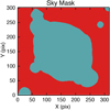 |
Fig. 1 Sky mask for the PA 33° exposures. The dark areas (green) are masked as non-sky (nebula and stars). |
3.2 Line emission measurement
The emission lines in each of the three final exposure level cubes were measured by fitting Gaussians to the 1D spectrum in each spaxel, using a line list derived from the tabulation of Fang & Liu (2013), taking account of line blending arising from the lower spectral resolution of MUSE. Not all lines in this extensive list were used: those above about 0.002 × F(Hβ) were searched and if above a given signal-to-noise (2.5) per spaxel, then they were fitted. Lines within a separation ≤ 10 Å (8 pixels) were fitted by a double Gaussian, up to a set of eight consecutive close lines. A cubic spline fit to the line-free continuum (of bound-free, free-free and 2-photon origin, and at the position of the central star, stellar continuum) provided the estimate of the continuum under the emission lines. The statistical errors for each voxel (Δ α, Δ δ, Δ λ element) delivered by the MUSE pipeline were considered to provide errors on the Gaussian fits from the covariance matrix of the χ 2 minimization (the MINUIT code (James & Roos 1975) is employed). The tables of line fits per spaxel were then processed into emission line maps with corresponding error maps. The mean of the ratio of the value to the propagated error (referred to as signal-to-error) is reported for the various quantities derived from the maps, such as line ratios, electron temperatures and densities, in the caption of the relevant figure.
Image quality with wavelength for final combined cubes (June 2014 data only).
4 Presentation of emission line maps
Since the velocity extent of the emission line components in NGC 7009 is ~60 km s−1 (Fig. A.1 of Schönberner et al. 2014), then, at the MUSE spectral resolution of ~100 km s−1, there is little velocity information on the kinematic structure: the maps of the emission line flux therefore encapsulate most of the information content. This study is primarily devoted to the emission line imaging; a following work will present analysis of integrated spectra of various regions. From the emission line fitting of each line (Sect. 3.2), images were constructed for each fitted line (a total of 60 such maps were produced). Figure 2 shows the three observed lines of O: O0 (from the [O I]6300.3 Å line, 120 s cube), O+ (from the [O II]7330.2 Å line, 120 s cube) and O++ (from the [O III]4958.9 Å line, 10 s cube, since the line is saturated in the 120 s cube); O+++ lines are not observed in the MUSE wavelength range. (All quoted wavelengths are as measured in air.) This set of images clearly shows the morphology by ionization, from the highly ionized more central region in [O III] through to the striking knots of ionization-bounded emission in [O I]. Figure 3 then shows some H and He line images: H+ as sampled by Balmer 4–2 Hβ 4861.3 Å from both the 10 s and 120 s cubes; He+ from the triplet (2P 3d – 3D 2 s) He I 5875.6 Å line (120 s cube); and He++ from the He II 5411.5 Å 7-4 line (120 s cube). The Hβ image shows the full range of ionized gas structures from the brightest inner shell with its strong rim, the converging extensions of the ansae, the minor axis knots (the northern one stronger) and the halo with its multiple rims – six can be counted (Corradi et al. 2004); see Balick et al. (1994) and Sabbadin et al. (2004) for the nomenclature of the nebula features. The fainter outer extensions found on the deepest ground-based images (Moreno-Corral et al. 1998) are not detectable on these images and this region was treated as part of the sky background.
While the morphology of the He I image is very similar to Hβ (Fig. 3), the high ionization He II image differs strongly. The He II emission is mostly confined within the bright rim and is strongest along the minor axis. However, between the rim and the ansae along the major axis there is patchy extended emission indicating a preferential escape of high ionization photons along the major axis as compared to the minor axis. The ansae (designated Knots 1 and 4 by Gonçalves et al. (2003) and indicated in Fig. 4), while seen in He+ and H+, are not detected in He++ emission. The inner shell is however not entirely optically thick to high ionization photons as there is He++ emission in the outer shell, which has a boxy appearance in Fig. 3.
Figure 4 shows a variety of other line emission images used in deriving diagnostics: the [S II]6716.4 Å line for Ne from the 6716.4/6730.8 Å ratio; [Cl III]5537.9Å for Ne from the 5517.7/5537.9 Å ratio; [N II]6583.5 Å for Te from the 5754.6/6583.5 Å ratio; and [S III]9068.6 Å for Te from the 6312.1/9068.6 Å ratio.
Figure 5 displays some ratio maps formed by dividing the observed emission line images over a range of ionization to demonstrate the pattern of excitation (of thermal and/or shock origin) and ionization from centre to edge, as well as the distinct lower ionization features. The low extinction (Paper I) has little effect on the morphology displayed in these images and the ratio maps are made with respect to a nearby H line. Figure 5 groups the ratio maps in order of decreasing ionization: from the highest ionization potential for which a good quality map could be derived (i.e., without a large fraction of unfitted spaxels falling below the 2.5 σ cut) [Mn V]6393.5Å/Hβ; He II 5411.5 Å/Hβ; [O III]4958.9 Å/Hβ; He I 5875.6 Å/Hα; [O II]7330.2 Å/Hα; [N II]6583.5 Å/Hα; [S II]6730.8 Å/Hα and [O I]6300.3 Å/Hα. The mean signal-to-error ratios over these maps are reported in the caption to Fig. 5; the peak values can reach >100 depending on the images composing the line ratio, and the peak value for the [O III]4958.9 Å/Hβ image is 207.
The He II/Hβ image differs most markedly from the other images and shows the loops on the minor axis prominently. The He I/Hα image forms the complement of the He II/Hβ one, except that the outer shell ismore prominent. [O III]/Hβ displays a higher ratio over the halo than the central shell regions; the positions of the ansae tips show enhanced [O III]/Hβ but, coincident with the strongest [N II] emission, show a decrease in [O III]/Hβ. The [O III]/Hβ and He I/Hα images show general correspondence of features over the inner shell but more structure in the former over the outer shell. The [O II]/Hα image is rather similar to the [N II]/Hα one except that the inner shell has more [O II] features2.
All the low ionization line images – [O II], [N II], [S II] and [O I] show a remarkably similar morphology and a number of well-known compact structures in the vicinity of Knots 2 and 3 (Gonçalves et al. 2003), indicated in Fig. 4 lower left (called “caps” by Balick et al. 1994). In the [N II]/Hα image, besides the ansae (K1 and K4 on Fig. 4), knots K2 and K3 are very prominent; the northern minor axis polar knot is also strong and its elongation is aligned along the vector to the central star (on HST images this is resolved into two sub-knots oriented radially). Similar to K1 and K4, knots K2 and K3 show enhanced [O III]/Hβ, but the peaks of [N II]/Hβ emission are slightly displaced (away from the central star) from the [O III]/Hβ peaks. The [O I]/Hα image is similar to [N II]/Hα and [S II]/Hα, except that the low ionization knots have higher contrast (diffuse [O I] is very weak). The [N I]5197.9, 5200.3 Å doublet is about six times fainter than [O I]6300.3 Å and, while it was detected in the low ionization knots with similar morphology to [O I], the S/N was not sufficient to derive a spaxel map without spatial binning.
Although the spatial resolution of the MUSE images in Fig. 5 is about four times lower than the Hubble Space Telescope (HST) WideField Planetary Camera 2 (WF/PC2) narrow band images, comparison of both sets is interesting (see Balick et al. 1998; Rubin et al. 2002). The HST images from Programmes 6117 (PI B. Balick) and 8114 (PI R. Rubin) allow emission line ratio images in [O III]/Hβ (although from 5006.9 Å and not 4958.9 Å as for MUSE data), [O I]/Hα, [N II]/Hα and [S II]/Hα to be formed for direct comparison with some of the images in Fig. 5. The same knots and features are seen in both sets, but with higher resolution of the individual features in HST images. The outward increase in [O III]/Hβ into the outer shell is seen in both sets but the outermost shells are more clearly revealed in the MUSE images. Similarly, the [N II]/Hα images are strikingly similar with a hint that knot K4 has developed a protuberance pointing SW in the more recent MUSE data (HST images from 1996). The level of [N II]/Hα over the high ionization centre of theinner shell is ~3 times higher in the HST image, presumably on account of the continuum contribution or uncorrected leakage of Hα into the [N II] passband (WF/PC2 F658N filter). Comparison of [O I]/Hα images showexcellent correspondence but again the HST image shows significant flux over the central core which is undetected in the pure emission line MUSE map.
Despite the absence of the brightest O II ORL’s (around 4650 Å) in the MUSE standard range, several of the strongest N II and C II recombination lines are captured. For N II, the multiplet 2s2 2p3p 3D–2s22p3s 3Po (V3) lines at5666–5730 Å are bright enough to be detected on a spaxel-by-spaxel basis in the 120 s cube. The (2-1) 5666.6 Å, (1-0) 5676.0 Å, (3-2) 5679.6 Å and (2-2) 5710.8 Å could be detected on many spaxels and were fitted. Figure 6 shows the map of the strongest line (5679.6 Å).
The strongest C II ORL in the spectral range is 3p 2P – 3s 2S at 6578.1 Å. This line was well detected in many spaxels but over the knots K2 and K3, where the [N II]6583.5 Å is very strong, the fitting was not reliable as the C II line lies in the wing of the [N II]6583.5 Å line which is >100 times stronger. In addition the other C II line from the same multiplet at 6582.9 Å makes for challenging line fitting at the measured spectral resolution of 2.8 Å. The C II 3d 2 D–3p 2P line at 7231.3 Å is however free from nearby bright lines and an adequate map could be produced, also shown in Fig. 6.
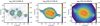 |
Fig. 2 Images of NGC 7009 in the O emission lines: O0 (from the [O I]6300.3 Å line, 120 s cube), O+ (from the [O II]7330.2 Å line, 120 s cube) and O++ (from the [Oiii]4958.9 Å 10 s cube). |
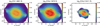 |
Fig. 3 Images of NGC 7009 in H and He emission line images: H+ as sampled by Balmer 4–2 Hβ 4861.3 Å fromboth the 10 s and 120 s cubes; He+ from the triplet (2P 3d – 3D 2s) He I 5875.6 Å line (120 s cube); and He++ from He II 5411.5 Å 7–4 line (120 s cube). |
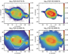 |
Fig. 4 Images if NGC 7009 in Ne and Te sensitive emission lines: [S II]6716.4 Å line for Ne; [Cl III]5537.9Å for Ne; [N II]6583.5 Å for Te; and [S III]9068.6 Å for Te. On the [N II] image the ansae are indicated and the designation of the various knots from Gonçalves et al. (2003). |
5 Mapping electron temperature and density
5.1 Te and Ne from collisionally excited species
Within the MUSE wavelength coverage, there are a number of sets of collisionally excited lines (CELs) that can be employed for electron temperature and/or density determination, depending on the sensitivity of the particular lines to Te and Ne. Among these are: [O I], [N II], [S III], [Ar III] for Te and [N I], [S II], [Cl III] for Ne. Among this set, the emission line ratios with sufficient signal-to-noise over the bright shells of the nebula, without binning the spaxels, to map Te and Ne, are presented: Ne from [S II] and [Cl III] (Fig. 7); Te from [N II] and [S III] (Fig. 8).
Diagnostic CEL maps were produced using the Python PyNeb package (Luridiana et al. 2015) using the default set of atomic data (transition probabilities and collision cross sections, in PyNeb version 1.1.3). PyNeb performs a five, or more, level atom solution of CEL level populations and thus explicitly treats the effect of collisional excitation and de-excitation dependent on electron density. The emission line flux maps were extinction corrected using the extinction map determined from the H Balmer and Paschen lines, as described in Paper I and using the Galactic extinction law (Seaton 1979; Howarth 1983) and the ratio of total to selective extinction, R, of 3.1. Line ratio maps were then formed from these extinction corrected images. The dereddened line ratio maps were masked in order that diagnostics were only calculated for spaxels with S/N of >3.0 on both lines and the error on the ratio per spaxel was calculated by Gaussian propagation of the errors on the emission line fits. The diags.getCrossTemDen task was employed to calculate simultaneously Te and Ne from [N II]6583.5/5754.6 Å and [S II]6716.4/6730.8 Å for the lower ionization plasma, and [S III]6312.1/9068.6 Å and [Cl III]5517.7/5537.9 Å for the higher ionization. The maximum number of iterations in diags.getCrossTemDen for the calculation of Te and Ne was set to 5, with the maximum error set to 0.1%. Errors on Te and Ne were also computed using a Monte Carlo approach with 50 trials of diags.getCrossTemDen assuming the errors on both sets of line ratios were Gaussian. Figures 7 and 8 show the individual maps of Ne and Te, respectively, and the means on the signal-to-error value over the maps are reported in the captions.
The [N II]5754.6 Å auroral line can be affected by recombination (direct and dielectronic recombination) to the 1S0 level of N+, leading to apparent enhancement of Te from estimation by the [N II]6583.5/5754.6 Å ratio (Rubin 1986)3. The [N II]6583.5 Å line is also affected by collisional de-excitation at Ne ≳ 104 cm−3, but such high densities are not apparent from the [S III]6312.1/9068.6 Å and [Cl III]5517.7/5537.9 Å ratio maps (Fig. 7). The contributionby recombination can be estimated using the empirical formulae of Liu et al. (2000). In order to employ this correction, N++ needs to be estimated (on a spaxel-by-spaxel basis) but no lines of [N III] are available in the optical range. A possible alternative is to use an estimate of N++ from a recombination line (N II); however the resulting ionic abundance may not match the CEL N++ abundance on account of the well-known abundance discrepancy factor between optical recombination lines (ORLs) and CELs; see Liu et al. (2006) for a detailed discussion of this topic.
One approach tried was to estimate the N++ ionic abundance from N+ and an empirical ionization correction factor for N++ based on the O++/O+ ratio4. Since the derivation of O+ from [O II]7320.0,7330.2 Å is also affected by recombination of O++, a correctionwas made; see Sect. 7. Even applying this approach the resulting value of Te over the central region (i.e. a Z-shaped zone inside the main shell) was very large, mean 14 600 K, somewhat lower than without any correction of ~15 200 K. Outside this Z-shaped region of elevated [N II] Te, the electron temperatureis well-behaved and matches Te from [S III] very well. Applying a multiplicative correction to the N++ abundance (on the assumption that the empirical correction by O++/O+ to N+ is underestimated), can indeed reduce Te over the central region, but at the expense of depressing the values outside this region. Applying a factor to N++ abundance large enough to decrease Te in the central region to values similar to [S III] Te, however depresses Te in the outer regions to values <5000 K, which cannot be justified (at least in comparison with the [S III] Te).
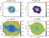 |
Fig. 5 Simple observed emission line ratio images (linear scale, × 100) with respect to an H line for NGC 7009, ordered by decreasing ionization potential of the nominator image: [Mn V]6393.5Å/Hβ; He II 5411.5 Å/Hβ; [O III]4958.9 Å/Hβ; He I 5875.6 Å/Hα; [O II]7330.2 Å/Hα; [N II]6583.5 Å/Hα; [S II]6730.8 Å/Hα and [O I]6300.3 Å/Hα. The 3× 3-σ clipped means on the signal-to-error above 3× the error on the ratio are: 8, 35, 47, 60, 26, 41, 34 and 29, respectively. |
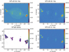 |
Fig. 5 continued. |
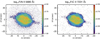 |
Fig. 6 Maps of two detected optical recombination lines are shown. Left panel: N II V3 multiplet 3p 3 D – 3s 3 P line at 5679.6 Å. Right panel: C II 3d 2D–3p 2P line at 7231.3 Å. |
5.2 Te and Ne from recombination species
The abundance discrepancy factor (ADF) for NGC 7009 is 3–5, the value depending on the ion (Liu et al. 1995a; Fang & Liu 2013). Since it is known that the ORL temperature and density indicators differ from the CEL ones for integrated long slit spectra, their spatial differences may prove helpful for better understanding of the ADF problem. Several diagnostic ratios of line and continuum from the recombination lines of H+, He+ and He++ in the MUSE wavelength range can be employed for electron density and electron temperature determination. These include the ratio of the high Balmer or Paschen lines as an electron density estimator (cf., Zhang et al. 2004), the magnitude of the H I Balmer or Paschen continuum jump at 3646 and 8204 Å respectively, the magnitude of the He II continuum jump at 5875 Å and the ratios of He+ singlets, which are primarily sensitive to Te. For the MUSE range the higher Paschen lines and the Paschen jump are accessible for H I and the He II and He I diagnostics are useful too. The He II Pfund jump at 5694 Å is however too weak to measure in the MUSE data except in heavily co-added spectra, such as the long slit spectrum studied by Fang & Liu (2011). The signal-to-noise in the maps is also not sufficient to determine Te and Ne diagnostics from N II and C III recombination lines on a spaxel-by-spaxel basis and the lines of O II are not available in the standard MUSE range.
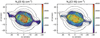 |
Fig. 7 Maps of Ne determinedfrom [S II] (left panel) and [Cl III] (right panel). The contours correspond to the observed log F(H β) image shownin Fig. 3 (left panel), with contours set at log10 F(H β) surface brightness (ergs cm−2 s−1 arcsec−2) from −15.0 to −11.8 in steps of +0.4. The electrondensities for collisional de-excitation of the [S II] and [Cl III] 2D3∕2 levels for these diagnostics are 3.1 × 10³ and 2.4 × 104 cm−3 at 104 K, respectively. The simple means on the signal-to-error value over the two Ne maps are 6 and 4, respectively. |
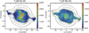 |
Fig. 8 Maps of Te determined from [N II] (left panel) and [S III] (right panel). The elevated values in the central region for the [N II] Te are assumed to be caused by the contribution of N++ recombination to the [N II]5754.6 Å line; see text for a consideration. The log F(H β) surface brightness contours are as in Fig. 7. The simple means on the signal-to-error value over the two Te maps are 52and 21, respectively. |
5.2.1 Te and Ne from He I
Zhang et al. (2005) showed how the ratio of the He I 7281.4/6678.2 Å lines provides a very suitable diagnostic of the He+ electron temperature and thus an interesting probe of the ORL temperature. They are both singlet lines, hence little affected by optical depth effects of the 2s 3S level, and are relatively close in wavelength (hence the influence of reddening on the ratio is small). The determination of Te from 7281.4/6678.2 Å was based on the analytic fits of Benjamin et al. (1999), applicable at 5000 < Te < 20 000 K, together with a fit to Te < 5000 K (Zhang et al. 2005). However, modern determinations of He I emissivities are based on the work of Porter et al. (2012, 2013), which are only tabulated for 5000 < Te < 25 000 K; thus the 3d 1D–2p 1 P0 (6678.2 Å) and 3s 1S–2p 1 P0 (7281.4 Å) emissivities were linearly extrapolated in log Te to temperatures below 5000 K from the Porter et al. (2012, 2013) values to 3000 K for the tabulated log Ne of 1.0 to 7.0.
The observed dereddened He I 7281.4/6678.2 Å ratio was converted to Te and Ne minimizing the residual with the theoretical ratio. A first guess for the value of Te was provided by the mean dereddened 7281.4/6678.2 Å ratio for the whole image of 0.16, corresponding to Te ~ 6500 K for an assumed Ne of 3000 cm−3. The ratio is much more sensitive to Te than Ne and the initial estimate for the He+ electron temperature of 0.65 × the [S III] Te was adopted; Ne was held fixed within narrow constraints during the minimization. Figure 9 shows the resulting He+ Te map, whichdisplays a distinct plateau inside the inner shell with mean Te of 6200 K and, in the outer shell, lower values with mean 5400 K, extending to <4000 K.
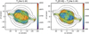 |
Fig. 9 The map of He+ Te (left panel)derived from the ratio of the He I singlet lines 7281.4/6678.2 Å. The mean signal-to-error value is 11. Right panel: difference map between the [S III] and He I Te maps. The log F(Hβ) surface brightness contours are as in Fig. 7. |
5.2.2 Te from H I Paschen Jump
The magnitude of the series continuum jump for bound-free (b-f) transitions of H I is sensitive to electron temperature. Following Peimbert (1971), Liu & Danziger (1993) developed the method using the flux difference across the Balmer jump normalized to the flux of a high Balmer line (Hβ in this case) and computed Te for several PNe. Zhang et al. (2004) also presented the same methodology applied to 48 Galactic PNe and extended the method to the flux across the Paschen jump using the Paschen 20 (8392.4 Å) line to normalize the flux across the jump for four PNe (including NGC 7009). It should be noted that the ratio of continuum fluxes of the blue to the red side of the jump is primarily dependent on Te (a slight dependence on Ne arising from the two-photon emission, see Appendix A), whilst the normalization by an emission line, with its emissivity dependent on Te and Ne, introduces amore significant dependence of electron density into the fitting of the jump.
The usual method to derive the flux difference across the jump is to fit the continuum spectrum, with the lines masked, in a dereddened spectrum by the theoretical continuum computed using H I recombination theory (cf., Zhang et al. 2004). Fang & Liu (2011) applied the method to a deep integrated spectrum of NGC 7009 and provide a fitting formula for Te as a function of the Paschen jump (defined as F(8194 Å) – F(8269 Å)) normalized by the Paschen 11 flux (8862.8 Å), all dereddened. In order to handle the tens of thousands of spaxels in the MUSE data, a method tuned to the dispersion of the MUSE spectra was developed. The mean continuum in several line-free windows on both sides of the Paschen Jump was measured and a custom conversion of this difference with respect to the flux of the P11 line was applied as a function of Te and Ne and the fractions of He+ and He++ with respect to H+ (see Sects. 7.1 and 7.2, respectively). A higher series Paschen line could have been chosen minimizing the uncertainty from reddening correction, but P11 has the advantage of being a strong line well separated from neighbouring lines and also occurring in a relatively clear region of the telluric absorption spectrum (Noll et al. 2012). Appendix A gives details of the selection of the continuum windows and the computation of the conversion from measured jump to Te, using recent computation of b-f emissivities from Ercolano & Storey (2006) and new computation of the thermally averaged free-free Gaunt factor from van Hoof et al. (2014).
No correction for the presence of stellar continuum on the Paschen Jump was applied (cf., Zhang et al. 2004). However, since the Paschen Jump Te is determined per spaxel, then spaxels over the seeing disk of the central star will be affected; the increase of the jump with increasing blue stellar continuum (and also when ratioed by P11) results in very low values of Te and these can be clearly discerned in the map. No other localized large deviations (positive or negative) of Te, not correlated with H I emission line morphology, were found, indicating no other significant sources of non-nebular continuum are present. Figure 10 shows the resulting map of PJ Te. The mean value is 6610 K with a root mean square (RMS) of 1010 K (3 × 3 σ clipped mean); the mean signal-to-error over the map, based on 100 Monte Carlo trials using the propagated errors on the measured PJ is 13.
5.2.3 Ne from H I high Paschen lines
Zhang et al. (2004) describe a method for determining Te and Ne from the decrement of the higher Balmer lines, and a similar method was applied to the high Paschen lines. Fitting reddening corrected images of P15 – P26 (8545.4, 8502.5, 8467.3, 8438.0, 8413.3, 8392.4, 8374.8, 8359.0, 8345.5, 8333.8, 8323.4 and 8314.3 Å) and minimizing the residuals against the Case B values for initial values of Te and Ne from [S III] and [Cl III] (Sect. 5.1) enables estimates of the H I recombination density to be estimated. Higher Paschen series lines than P26 begin to be significantly blended at the MUSE resolution of ~3 Å and were not used. The set of higher Paschen lines is more sensitive to Ne than Te (cf. Fig.1 in Zhang et al. 2004), so a given Te was adopted per spaxel from [S III] and [Cl III] (Sect. 5.1), although Te from the Paschen decrement (Sect. 5.2.2) could have been used.
It was noted that P22 (8359.0 Å) has a much higher strength than predicted by Case B at reasonable values of Te and Ne; the same behaviour was found by Fang & Liu (2011; see their Fig. 7) from their long slit spectrum of NGC 7009. In their data P22 does not appear to be much above Case B within the errors, but for an integrated spectrum of the bright rim to the NW of the central star, the MUSE data clearly show P22 to be unusually strong (factor 1.8). No obvious He I or He II recombination lines coincide with the wavelength of H I P22, so another species may be contaminating this line (or the apparent strength arises from sky subtraction errors). P22 was therefore removed from the comparison of observed v, predicted Paschen line strengths. The Paschen line strengths were compared to the Case B values at the value of Te for each spaxel, weighting by the signal-to-noise of each line to determine Ne; the initial value of Ne from the [Cl III] ratio was used. The signal-to-noise ratio of the fitted emission lines is only high enough in the highest H I surface brightness regions, so the resulting map has sparse coverage of the outer shell. In a number of spaxels no solution was possible within the errors and the initial value of Ne was adopted. Figure 11 shows the resulting H I Ne map; high values are seen at the positions of the minor axis knots, corresponding to strong He II emission. The mean value of the map is 4250 ± 3030 cm−3, compared to the mean value for the [Cl III] Ne of 3490 ± 1930 cm−3 (3σ, 3 clipped iterate means).
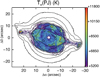 |
Fig. 10 Map of Te derived from the magnitude of the Paschen continuum jump at 8250 Å ratioed by the dereddened H I Paschen 11 (8862.8 Å) emission line strength. Initial estimates of Te and Ne from the [S III] and [Cl III] ratio maps (Sect. 5.1) were applied, followed by two iterations with the derived Te map from the Paschen Jump. See text for details. The low Te values over the central star are not representative and arise from the strong stellar continuum. The log F(H β) surface brightness contours are as in Fig. 7. The mean signal-to-error is 13. |
5.3 Comparison of Te and Ne maps
Maps have been presented of Te from two CEL line ratios ([S III] and [N II], Fig. 8) and two ORL combinations – He I 7281.4/6678.2 Å singlet line ratio (Fig. 9) and H I Paschen Jump (Fig. 10) and maps of Ne from the two CEL ratios ([Cl III] and [S II], Fig. 7) and one ORL diagnostic from the high series H I Paschen lines (Fig. 11). These data provide a unique opportunity to spatially compare the various diagnostics of CEL and ORL origin. No information about the line-of-sight (radial velocity) variation of CEL and ORL diagnostics is however available from these maps given the low spectral resolution of MUSE.
Te from the [N II] line ratio is strongly affected by recombination to the upper level (auroral) 5754.6 Å line and the resulting Te ’s are too high, particularly in the central region; thus the CEL comparisons can only reliably be made with the [S III] Te map. Fang & Liu (2011) measured a Te value from the [S III] ratio of 11 500 K, in comparison with 10 940 K from the [O III] ratio (their Table 4). Lacking measurement of [O III]4363.2 Å and a map of Te (O++) with MUSE, then Te from the [S III] ratio is the best CEL Te surrogate for probing the bulk of the ionized emission.
The CEL [S III] Te map (Fig. 8) shows the highest values of 10 300 K in the inner shell minor axis lobes, which correspond to the strongest He II emission (and, as shown in Sect. 7.2, the highest He++/H+). Within a circular plateau of radius 4.5″ around the central star, the Te values are high. Inside the inner shell along the major axis there are regions of lower Te by ~500 K except for two almost symmetrical stripes perpendicularly across the major axis (offset radii 9.5″) with slightly elevated Te of ~450 K above their surroundings. These elevations in Te correspond to knots K2 and K3 (Gonçalves et al. 2003), indicated in Fig. 4. The outer shell has a lower and more uniform Te appearance with a value ~8900 K, including the ansae, but there are two regions along the minor axis which have Te depressed by ~100 K. The ansae, however, notably show higher Te with values around 10 600 K, similar for both ansae, with values increasing to the extremities (to 11 000 K). All these comparisons show differences larger than the propagated errors on Te (Sect. 5.1).
Although the central region with higher ionization in the [N II] Te map is strongly affected by the N++ recombination contribution, the outer regions should be less affected (see Fig. 8). The ends of the major axis show Te values elevated by only about 1000 K with respect to [S III] Te but the outer shell displays values higher by 1000’s of K suggesting that N++ recombination also contributes in this region. The extremities of the ansae show [N II] Te notably lower than from [S III], while the emission extends further along the minor axis than S++.
Comparison of the He I singlet line ratio and H I Paschen Jump Te maps (Figs. 9 and 10, respectively) show many similarities with a lower temperature circular region around the central star and elevations at the ends of the major axis; the contrast between the higher Te inner shell and the outer shell is greater (by ~500 K) for the He I Te map, and in general the He I map is smoother. The He I Te map is very different in value and appearance from the [S III] Te map (Fig. 8). The mean temperature difference in the inner shell is 2500 K whilst in the outer shell it is 3500 K. There is a distinct step in the temperature difference (Δ Te ([S III] − He I)) ~ 1000 K at the outer edge of the main shell. Both Te maps show a central circular depression in Te with elevations towards the ends of the major axis, with some general correspondence to the positions of the K2 and K3 knots. Both Te maps show elevations up to ~1500 K over the minor axis polar knots, well above the errors. Very prominent is the elevation in Te at the extremities of the ansae, with values increasing from the He I Te map (~7200 K) to the H I PJ map (~9200 K), compared to the values of ~10 500 K in the [S III] Te image.
The Ne maps from the [Cl III] and [S II] line ratios (Fig. 7) show some similarities, such as the higher density inner circular region around the central star, with Ne ~ 7000 cm−3, but also some differences. Several notable holes in the higher ionization Ne map with sizes ≲1″ are apparent in the inner shell, but not in the lower ionization density map. The edges of the inner shell on the minor axis display prominently elevated Ne (to 8000 cm−3). However, the western filament (K2) shows as a depression in [S II] Ne, although not in [Cl III] Ne. Both maps show the northern polar knot over the outer shell with density peaking at above 6000 cm−3. The ansae are undistinguished in both CEL Ne maps with values averaging 2200 cm−3.
The ORL Ne map from the ratio among the high Paschen lines (Fig. 11), although of rather low significance, does show general similarities to the [Cl III] Ne map. The central circular region however has Ne elevated by ~3000 cm−3 with respect to the [Cl III] density map and the features along the minor axis have higher density with a bi-triangular morphology. There are similarities in this morphology with the He II/Hβ image (Fig. 5) showing that the regions of highest ionization are of high density. An incidental similarity also occurs with the [N II] Te map (Fig. 8) which probably arises from the large contribution to [N II]5754.6 Å emission from recombination of N++ (Sect. 5.1) in this high ionization region.
It is pertinent that regions distinguished by their emission line surface brightness, in addition to the obvious shell structure, such as the K2 and K3 filaments, the minor axis polar knots and the ansae, also display distinct physical properties, such as elevated, or depressed, Te and Ne. This suggests a fundamental link between emission line morphology and physical conditions, which might indeed have been expected, but is nevertheless re-assuring and lends physical justification to the many decades of emission line morphological studies of PNe.
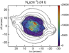 |
Fig. 11 Map of Ne derived by comparing the strengths of the higher Paschen lines (P15 – P26) with the Case B predictions, adopting Te values provided by the [S III] ratio. The log F(Hβ) surface brightness contours are as in Fig. 7. The mean signal-to-error is 2. |
5.4 A map of the temperature fluctuation parameter t2
Comparison of the maps of Te from the CEL line ratio for [S III] and the ORL Paschen Jump provide a method to study the spatial variation of the temperature fluctuation parameter, t2, introduced by Peimbert (1967). Given that there may be temperature variations within a nebular volume, Peimbert (1967) showed how the difference between Te values from the ratio of the Balmer jump to Hβ, compared toTe from the [O III]5006.9/4363.2 Å ratio, can be used to derive the mean temperature T0 and the root mean square temperaturefluctuation, t2, by series expansion to 2nd order. Zhang et al. (2004) applied the method to several nebulae including NGC 7009, considering also the Te independence of the far-infrared [O III]88.33/51.80 μm ratio.
The MUSE spectra do not include the Balmer jump at 3646 Å or the [O III]4363.2 Å line, but the problem can be reformulated following Peimbert (1967) using the [S III]9068.6/6312.1 Å ratio and the Paschen Jump to Paschen 11 ratio (see Appendix A). The equivalent dependencies are (cf., Peimbert (1967), Eqs. (18) and (16), respectively):
![Mathematical equation: \begin{equation*} T_{\rm{e}}([\hbox{{S}\,{\scshape{iii}}}]) = T0\left[1 + \frac{1}{2} \left(\frac{5.537\times10^{4}}{T0} - 3\right)t^{2}\right]\end{equation*}](/articles/aa/full_html/2018/12/aa33445-18/aa33445-18-eq1.png) (1)
(1)
and
 (2)
(2)
where the latter relation was determined by fits to the variation of PJ and P11 emissivity with Te at a density of 3500 cm−3 (see Appendix A and Storey & Hummer 1995).
From the [S III] Te image (Fig. 8) and the PJ/P11 Te image (Fig. 10), the average temperature T0 and the temperature fluctuation parameter t2 were determined by minimizing the difference of the observed Te ’s against the difference from Eqs. 1 and 2. Figure 12 shows the T0 and t2 maps: the (3-σ clipped) mean values are 7900 K and 0.075, respectively. Since the [S III] Te map always has higher values, it dominates the morphology of the T0 image, but is reduced on average by ~15% (1200 K). The t2 map on the other hand more closely resembles the PJ Te map and is by no means uniform, with a demarcation between the inner (lower t2) and outer (higher t2) shells. In particular the central He II zone has elevated t2, while the ends of the inner shell major axis and the north minor axis polar knot have lower values (by ~0.05); the ansae, particularly the eastern one, also show lower values of t2, with mean 0.03. The outer rim of large t2 values is not necessarily real and is accountable to large errors in [S III] and PJ Te; the large values over the central star are also not real on account of stellar continuum contamination of the Paschen Jump (Sect. 5.2.2).
Given such large values of t2, it can be argued that the definition of Peimbert (1967) in terms of a Taylor series expansion of Te to account for differences in temperature along the line of sight breaks down, and so the description of the differences in Te between a collisionally excited line indicator and a recombination line/continuum indicator in terms of t2 is no longer strictly valid. A higher order temperature fluctuation parameter could be sought for a quantitative description of this regime.
6 Extending diagnostics to faint outer regions
On account of the lower surface brightness of the emission from the halo beyond the outer shell, at the resolution of single spaxels the S/N is too low to fit more than a few of the strongest emission lines (e.g., strong H Balmer lines, [O III], etc). In order to explore the physical conditions in the halo, binning of the spaxels is required to achieve an adequate S/N for line fitting (conservatively considered to be >2.5 σ). The data can be binned either into regular n × m spaxels bins or an adaptive signal-to-noise based criterion can be used to construct the bins, which need not be rectangular. The adaptive binning technique based on Voronoi tesselations, developed by Cappellari & Copin (2003) specifically for IFS data, provides a natural choice. The high S/N of single spaxels in the bright inner shell is retained, whilst some binning is applied in the outer shell and large and irregular shaped bins are appropriate for the halo.
The IDL V ORONOI_2D_BINNING code based on Cappellari & Copin (2003) was used to generate the bins based on the 120 s Hβ image and atarget S/N of 500 was used: this choice leaves the spaxels in the bright inner shell with low rebinning (typically 2 × 2 spaxels) and results in very large bins in the outer regions; Fig. 13 shows the binned Hβ map. The cubes were rebinned with the spectra set by the binning but on the original pixelation. Each spaxel spectrum was then fitted by multiple Gaussians, as described for the unbinned data (Sect. 3.2), and some maps of line flux and flux error were generated, Fig. 13 being an example.
The Voronoi tesselated images were then subjected to a similar analysis to the unbinned images: the extinction was obtained from the ratio of the 10 s Hα and 120s Hβ images (since the H Paschen images have much lower S/N, the lines were not detectable in much of the halo so only the Balmer line images were employed for extinction determination); the emission line images were dereddened; line ratio maps were formed with propagated errors and used to determine Te and Ne from the same diagnostic lines as the unbinned data (Sect. 5). Since Te and Ne are required to compute c by comparison to the Case B H Balmer line ratio, an iterative procedure was adopted for the outer regions, with initial values of 104 K and 1000 cm−3 for Te and Ne, respectively. After two iterations of determining c, dereddening and recomputing Te and Ne, the mean values in the outer regions were found to be 11 500 K and 400 cm−3.
The extinction map notably displays negative values in the outer extensions of the halo visible within the MUSE field of view. This finding was independently confirmed by fitting ellipses to the 10 s Hα and 120 s Hβ images and examining the ratio of surface brightnesses as a function of radius. Above a radius of 130 pix (26″), the Hα /Hβ ratio falls below the Case B value of 2.855, appropriate for the nebula plasma conditions in the inner shell. A negative value of c cannot be derived ifthe appropriate density and temperature in the ionized gas are chosen and the correct optical depth condition in the Lyman continuum (Case A/B). The effect is most probably caused by a component of scattered Balmer light from the bright central nebula (≳103 times the surface brightness of the halo) and the presence of a scattering medium, predominantly dust, since Paper I showed the presence of dust within the nebula.
Some instrumental component of scattered light from the bright inner shell into the outer shell must occur, although no direct evidence was seen by comparing the longer and shorter exposures and brighter and fainter emission lines between the two instrumental position angles. According to the MUSE instrument manual (Richard et al. 2017), both internal ghosts and straylight are below the 10−5 level. Sandin (2014) has carefully considered the role of diffuse scattered light in observations of extended objects and derived surface brightness profiles. There must be some contribution to the halo light from the diffuse scattered profile of the inner shell of NGC 7009, but the presence of several rims in the faint halo (e.g., Moreno-Corral et al. 1998) suggest this cannot be the dominant effect. The scattering problem for Hα and Hβ in a PN with aneutral dust shell has been treated by Gray et al. (2012); in the case of NGC 6537 they derived a clumpy distribution of dust in the shell. Linear polarization has also been measured by Leroy et al. (1986) over the outer halo of NGC 7009, so the prediction from these observations is that a higher value of polarization is expected over the faint halo (cf., Walsh & Clegg 1994 for the halo of NGC 7027).
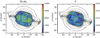 |
Fig. 12 Maps of the average temperature (T0, left panel) and the temperature fluctuation parameter (t2, right panel) determined from the [S III] and the Paschen Jump Te maps. The log F(Hβ) surface brightness contours are as in Fig. 7. The mean signal-to-error over the T0 map is 45 and for the t2 map is 15. |
7 Ionization maps
For those ORL’s and CEL’s with sufficient signal-to-noise to allow coverage of the main shell and outer shell, maps of the ionic fraction with respect to H+ were formedusing PyNeb. The maps ofTe from [S III] and Ne from [Cl III](Sect. 5) together with the dereddened line and Hβ maps (applying the Seaton (1979) extinction law with R = 3.1) were employed to generate the ionic abundance at each spaxel. The following ionic maps were made: He+ and He++; N+; O0, O+ and O++; S+ and S++; Cl++ and Cl+++; Ar++ and Ar+++; and Kr+++.
7.1 He+
There are a range of singlet and triplet He+ lines in the MUSE coverage, some of which are affected by optical depth and by collisional effects from the 2 3 3S and 2 1 1S levels, although neither should be severe in NGC 7009. The He+ abundance was calculated by PyNeb using the Case B emissivities of Porter et al. (2012, 2013). The He+ /H+ abundance can be determined from He I 5875.6 Å (3d 3 D–2p 3 P0, triplet), 6678.2 Å (3d 1D–2p 1 P0, singlet), 7065.7 Å (3s 3S–2p 3 P0, triplet) and 7281.4 Å (3s 1S–2p 1 P0, singlet) lines. The other singlet He I lines detected are 4d 1 D–2p 1 P 4921.9 Å and 2s 1 S–3p 1 P 5015.7 Å; however, the 4921.9 Å line is weaker than the red He I lines and the 5015.7 Å line is very close to the very bright [O III]5006.9 Å line, so is very problematic to obtain a good line flux. It was decided therefore to concentrate on the four red and brighter He I lines to provide better spatial coverage of the fainter regions. Of these lines, He I 7065.7 Å is the one most sensitive to the He I τ (3888.6 Å) optical depth (Robbins 1968), followed by 5875.6 Å, while the singlets 6678.2 Å and 7281.4 Å are entirely insensitive to τ (3888.6 Å).
The He+ maps based on the He+ Te (Sect. 5.2.1) and the singlet 6678.2 Å and triplet 5875.6 Å images are very similar in appearance and mean value, while the He+ map from 7065.7 Å has a much higher mean value, although similar morphology. The difference arises since the 7065.7 Å mapshows the effect of higher He I 3888.6 Å optical depth with a morphology of a ring around the inner shell.
A τ(3888.6 Å) optical depth map can be calculated from the ratio of He+ maps from the He I 7065.7 Å and He I 6678.2 Å lines, following Eq. 5 of Monreal-Ibero et al. (2013). However, in the case of NGC 7009, τ (3888.6 Å) should be calculated appropriate for an expanding nebula (Monreal-Ibero et al. 2013 used a fit to the Robbins 1968 He+ emissivity appropriate to a static nebula), so a new fit was made for the case when the ratio of radial velocity to thermal velocity (V (R)∕V (TH) in Robbins (1968, Table 3) is 5, although the value in NGC 7009 is higher than this, ~20. It should be noted however that the variation of 7065.7 Å optical depth appropriate for Te of 104 K was used, as Robbins (1968) only tabulates the variation at two values of Te. The ratio of He+ /H+ images between 7065.7 and 6678.2 Å was used to compute τ (3888.6 Å) and the resulting map is shown in Fig. 14. The value of τ (3888.6 Å) is quite high, mean 15.0, with some structure associated with the boundary of the inner rim and outer shell. Notably, there is less structure than in the same map produced from the He+ images with [S III] Te where there are prominent holes in the optical depth map on the minor axis, but the mean value of τ (3888.6 Å) is lower (mean 2.0). Interestingly, Robbins (1968) deduced a (single) optical depth value for NGC 7009 of 15, based on Te of 104 K. Given the relatively high value of τ(3888.6 Å) derived here, calculating He+ Te from 7281.4/5875.6 Å can be expected to deliver a lower value of Te (cf., Zhang et al. 2005) since 5875.6 Å is a triplet line.
The strongest He I singlet line, hence showing no optical depth sensitivity, is 6678.2 Å, and Fig. 15 shows the ionic fraction He+ /H+ using the Hei Te, the [S III] Te for H+ and the single [Cl III]Ne map.
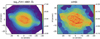 |
Fig. 13 Left panel: Voronoi tesselated version of the 120 s Hβ emission line image, in a log display showing the adaptive bins. Right panel: extinction map, c(Hβ), for the Voronoi tesselated images based on the ratio of the 120 s Hβ image and the 10 s Hα images. |
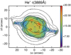 |
Fig. 14 τ(3888.6 Å) from the ratio of He I 7065.7 Å and 6678.2 Å lines, calculated with the He I Te map and a ratio of expansion velocity to thermal velocity for the nebula of 5. The log F(H β) surface brightness contours are as in Fig. 7. |
7.2 He++
The He++ map produced with the dereddened HeII and Hβ images and the [S III] Te and [Cl III] Ne maps (Sect. 5.1) is shown in Fig. 16. It shows the high ionization main shell with the minor axis regions prominent, where He+ is notably lower. Whilst thereis weak He++ present in the outer shell, it is more pronounced along the major axis. This suggests an anisotropic escape of highly ionized photons, with much higher optical depth to hν ≥ 54.4 eV photons along the minor axis than the major axis, although in other respects the major axis extensions are fairly unassuming with similar extinction, Te and Ne to the rest of the outer shell (Sect. 5.1). The extensions of the He++ emission beyond the inner shell contrast with the Chandra diffuse X-ray appearance (Kastner et al. 2012, their Fig. 4), which displays soft X-ray emission only inside the main shell, and attributed to the interface between the shocked stellar wind and the cooler, denser expanding gas of the optical nebula.
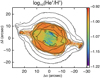 |
Fig. 15 Map of He+/H+ determined from the He I 6678.2 Å and Hβ dereddened emission line maps with the He+ Te and [S III] Te maps, respectively, and the single [Cl III] Ne map. The log F(Hβ) surface brightness contours are as in Fig. 7. The mean signal-to-error ratio on He+ /H+ is ~14. |
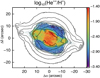 |
Fig. 16 Map of He++/H+ using the [S III] Te and the [Cl III] Ne maps. The log F(Hβ) surface brightness contours are as in Fig. 7. The mean value of signal-to-error is 12. |
7.3 O0, O+ and O++
Figure 17 shows the O0, O+ and O++ maps; the quoted mean signal-to-error values are from Monte Carlo trials. The O+ abundance was formed by correcting the dereddened [O II]7330.2 Å line flux by the O++ recombination contribution. The correction scheme proposed by Liu et al. (2000) was adopted (their Eq. 2, detailed in their Appendix A) and the O++/H+ contributionwas provided by the O++ map based on the[S III] Te map. This contribution for O++ recombination alters the mean value over the map of O+ /H+ by 30%.
The O0 abundance, calculated assuming pure photoionization and Te and Ne from [S III] and [S II], respectively, is only strong in a few knots along the major axis, in the ansae and knots K2 and K3. There may however be some component of fluorescence to [O I] emission or it may be predominantly produced in photodissociation regions (cf., Richer et al. 1991; Liu et al. 1995a), so the O0 cannot naively be added to O+ and O++ to determine the total O abundance (although it only contributes at the level of 0.25% of the total O abundance). The northern minor axis peak is strong in O0 as are several compact knots in the vicinity of the western major axis knot K2. The map of O+ bears many similarities to the O0 but with more extended emission present over the inner and outer shells. The ansae are notably strong in O+. The O++ map is notably extended to the outer shell and towards the ansae, but depressed at the ansae themselves. The lower O++ regions in the inner shell correspond to those with highest He++, consistent with strong O+++ presence.
7.4 N ionization maps
Only the N+ image is available from the CEL [N II] lines but, as shown in Sect. 5.1, the 5754.6 Å line is affected by recombination and so over-estimates Te; to produce the N+ /H+ map shown in Fig. 18, Te from [S III] and Ne from [S II] were employed. The map resembles closely that of O0 (Fig. 17) with the low ionization knots prominent. However, the N++/H+ map from the N II ORL 2s2 2p3p 3De – 2s22p3s 3 Po (3-2) 5679.6 Å line (recombination of N++ to N+) is markedlydifferent in appearance (Fig. 18). The ORL N++/H+ map was formed using the [S III] Te and [Cl III] Ne (the latter only 500 cm−3 higher in the mean than the [S II] Ne image) in the event of not having a spaxel-by-spaxel map of N II ORL Te (see Sect. 5.2). This ORL N++/H+ image resembles the Ar+++ map (shown in Fig. 19), and the ionization potentials substantially overlap (29.6 < N++ < 47.4 eV; 27.6 < Ar+++ < 40.7 eV).
7.5 S, Cland Ar ionization maps
The other species for which maps of several ionization states from CEL lines can be formed are S (S+, S++ from [S II] 6730.8 Å and [S III]9068.6 Å respectively), Cl (from Cl++ and Cl+++ from [Cl III]5537.9 and [Cl IV]8045.6 Å) and Ar (Ar++ and Ar+++ from [Ar III]7134.8 and [Ar IV]7237.4 Å). Figure 19 shows the S, Cl and Ar ionization maps. The morphology of the lower ionization species (S+, Cl++ and S++ and Ar++, ionization potentials 10.4–27.6eV) are quite similar, and to O+, but the appearance of the Cl+++ and Ar+++ (IP’s to 39.6 and 40.7 eV, respectively) differ strongly, and also from the O++ (Fig. 17). Neither Cl+++ and Ar+++ show the central ionic emission with a depression, as shown by O++; the Cl+++ has a bipolar appearance with the outer shell minor axes enhanced and Ar+++ has a curious four-cornered (biretta) shape extending into the outer shell.
8 Abundance maps
8.1 He abundance
The only species for which a total abundance map can be formed without invoking use of an explicit ionization correction factor (ICF) map is He. Given that there is no reliable diagnostic for the fraction of He0 in an ionized nebula, the default assumption is made that it represents a negligible proportion: the sum of He+ and He++ should therefore map the total He abundance. This assumption is reinforced by the 1D photoionization models presented inSect. 9.1, based on an integrated spectrum, where both show neutral He fractions <0.15%. The simplest assumption, following Occam’s razor, is that the He abundance in the nebular shells is uniform. Helium is a general product of Big Bang nucleosynthesis and is supplemented by stellar H-burning phases, which begin on the main sequence and are first brought to the surface by the first dredge-up, and later, principally, during third dredge-up on the asymptotic giant branch. By comparison of L, Teff from Sabbadin et al. (2004) with the Miller Bertolami (2016) solar abundance evolutionary tracks, an initial mass of 1.4 M⊙ and a current mass of 0.58 M⊙ are derived. Thus, second dredge-up is not expected to have occurred in NGC 7009 (cf., Karakas & Lattanzio 2014).
Figure 20 shows the He/H+ map formed from the He+ /H+ map (Fig. 15) and the He++/H+ map (Fig. 16), where all (He and H) emissivities were calculated with Te from [S III] and Ne from [Cl III] (Sect. 5.1). There does not appear to be evidence that the He/H+ values are depressed in the knots K1–K4 (Fig. 4), suggesting no enhanced contribution from He0 in these low ionization regions.
The flattest map of total He abundance was produced by using the values of Te from [S III] (Sect. 5.1) for both He++ and He+ with respect to H+. Adopting Te from He I 7281.4/6678.2 Å (Sect. 5.2.1) for calculating the emissivity of both He+ and H+, and the [S III] Te map for both He++ and H+, leads to a map displaying stronger residuals from flatness, corresponding to the inner and outer shells and the region of He++ emission (see Fig. 16); the mean and 3-σ RMS on this image was 0.1057 ± 0.0061. The map produced solely from [S III] Te resulted in a mean and 3-σ RMS of 0.1079 ± 0.0025. If the Paschen Jump Te map is used to calculate the He+ and H+ emissivities, the map is far from flat, the He++ regions are enhanced and the outer shell has values of He/H+ of around 0.085, worryingly close to the primordial He/H value of 0.0745 (He4 mass fraction 0.24709 ± 0.00017 (Pitrou et al. 2018) given the heavy element abundances of NGC 7009; Fang & Liu 2011).
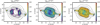 |
Fig. 17 Maps of O0, O+ and O++/H+ ionic abundances. The log F(Hβ) surface brightness contours are as in Fig. 7. The mean signal-to-error values on O0, O+ and O++/H+ are 12, 21 and 13, respectively. |
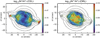 |
Fig. 18 Map of N+/H+ from the CEL [N II] lines (left panel) and for N++/H+ from the N ii5679.6 Å ORL line (right panel). The log F(Hβ) surface brightness contours are as in Fig. 7. The mean values of signal-to-error are 15 and 5, respectively. |
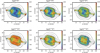 |
Fig. 19 Maps of S+ and S++, Cl++ and Cl+++ and Ar++ and Ar+++/H+ ionic abundances. The log F(Hβ) surface brightness contours are as in Fig. 7. |
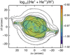 |
Fig. 20 Sum of He+/H+ and He++/H+ using the [S III] Te and [Cl III] Ne maps for He+/H+ and He++/H+ computation. The log F(Hβ) surface brightness contours are as in Fig. 7. |
8.2 O abundance
Typical ICF schemes employ the He+ and He++ ratios to correct for the presence of O+++, which is notcovered by optical ground-based spectroscopy since [O IV] lines occur in the ultra-violet and infrared (see Phillips et al. 2010 for the latter). Several ionization correction schemes have been developed, starting with Torres-Peimbert & Peimbert (1977), followed by Kingsburgh & Barlow (1994) and Delgado-Inglada et al. (2014), primarily based on proximity of ionization potentials in various ions and, in the later work, through development with photoionization models. Recently, Morisset (2017) suggested that in the era of IFUs and 3D ionization codes, ICFs can be allowed to vary spatially depending on the local ionization conditions, dictated by the model. For the simplest expectation that the abundance of O is uniform across the nebula, then large scale discontinuities coincident with ionization boundaries and physical features, such as ansae, polarknots etc., should not be expected. However, this simple assumption should not preclude small-scale abundance differences, such as associated with H-poor knots in born again PNe, for example, Abell 78 (Jacoby & Ford 1983).
Figure 21 shows the comparison of the total O abundance from the ICF’s of Torres-Peimbert & Peimbert (1977), Kingsburgh & Barlow (1994) and Delgado-Inglada et al. (2014). It is clear from these maps that the correction is not complete enough as a deficit remains in the central regions where the He++ is strong. All three ICF’s need a 20–30% correction for the presence of O+++. However, there are also traces of the inner rim in the He abundance map, coincident with the peak of the wave in the dust extinction map shown in Paper I. This feature in the region of the ionization front may indicate that the conditions in the He++ zone, and possibly also in the He+ zone, may not be well diagnosed by adopting the [S III] Te values.
Based on the detections of lines such as [K VI], [Mn VI] and [Fe VI] by Fang & Liu (2013; although these lines are very weak), there may be expected to be some ions with energies above 60 eV present in the nebula, so correction for the presence of O4+ must be considered. However, in principle, the O ICF schemes should include all ionic stages above O++. A weaker alternative proposition is that the ICF is too low even where He++ is not present; increasing the ICF could raise the correction, including in the regions with strong He II emission, such that the discrepancy over the He++ region is reduced.
8.3 N/O abundance
The classical method of deriving the N/O abundance ratio is based on the assumption that N+ and O+, on account of the similarity of their ionization energies, are co-located; thus a simple ratio of their ionic emission can be employed to determine the total N/O (Peimbert & Costero 1969; Peimbert & Torres-Peimbert 1971b; Kaler 1979); N/O is an important diagnostic of the dredge-up enrichment of the nebula by the central star. The resulting N/O map is shown in Fig. 22. The simple mean value of N/O is 0.132 but the values are far from constant and range over more than an order of magnitude to >1 at the extremities of knots K1 and K4, as noted by many works. Although developed on long-slit or nebula integrated spectra, and compared with 1D photoionization models, it clear that, at least in the case of NGC 7009, this scheme for determining total N/O is a gross over-simplification, as demonstrated by Gonçalves et al. (2006).
The ionization energies for O+ and N+ are 13.6–35.1 and 14.5–29.6 eV, respectively; thus the range of N+ ionization energies is entirely contained within that of O+. However, the physical conditions in NGC 7009, and perhaps also the central star far-UV energy distribution, disfavour these ions being co-extensive within the nebula volume and this method appears to be ill-suited to a spatially resolved ionization correction scheme. Gonçalves et al. (2006) from 3D photoionization modelling point out that the difference in ionization potentials make the spatially resolved ratio N+ /O+ very sensitive to the shape of the local radiation field. A relatively large fraction of N must be in the form of N++ over a substantial area of the nebula, such that correcting the amount of N+ by including ionization energies up to 35.1 eV could lead to a flat N/O map, as suggested by the N++/H+ ORL map (Fig. 18).
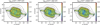 |
Fig. 21 Maps of total O/H+ abundance for three ionization correction factors adjusting for the presence of O+++. Left: the ’classical’ scheme of Torres-Peimbert & Peimbert (1977); centre: the corrected classical ICF advocated by Kingsburgh & Barlow (1994); right: the model-based approach of Delgado-Inglada et al. (2014). The log F(Hβ) surface brightness contours are as in Fig. 7. |
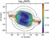 |
Fig. 22 Map of the N/O abundance based on the N+/H+ and O+ /H+ maps (Figs. 18 and 17, respectively). The log F(H β) surface brightness contours are as in Fig. 7. The mean value of signal-to-error is 13. |
9 Integrated spectra
Integral field data provide an ideal basis for constructing summed spectra of regions defined by a variety of geometrical (or other) criteria. These spectra have enhanced signal-to-noise based on the summation of spectra in many pixels and can lead to the detection of lines much fainter than are accessible in the spaxel maps. In the case of NGC 7009, summed (spatially integrated) spectra over its specific morphological features can be formed: in addition to the obvious ones of inner shell, outer shell and halo, summationsover the ansae, high ionization poles on the minor axis (Fig. 16), the cusp in the extinction map (Paper I) or the higher density lobes on the minor axis (Fig. 7) can be analysed, for example.
Specific geometrical regions can be defined, such as slits and apertures that sample those from previous studies, to determine how the derived physical quantities (and abundances) relate to the total (nebula summed) values. A specific example is the long-slit spectrum, 2″ wide, situated 2–3″ south of the central star oriented along the major axis (PA 79°), in the deep spectroscopic study by Fang & Liu (2011, 2013). This slit was numerically constructed and the total spectrum was formed by all those spaxels within this slit. Figure 23 shows the simulated slit on the Hβ emission line image. The slit samples 14.2% of the total Hβ flux (based on the Hβ image) but since the He II emission is considerably extended along the ansae (Fig. 5), fully 17.2% of the total He II emission is sampled by this slit, presenting a slightly higher ionization view of the entire nebula. Given the diversity of data and instruments used in the Fang & Liu (2011, 2013) study, the MUSE spectrum from this simulated slit serves as a useful fiducial for this verydeep (and higher spectral resolution) spectrum.
One of the “bonuses” of IFU spectroscopy of an entire Galactic planetary nebulae is the total spectrum integrated out to the halo, which can be compared to truly integrated spectra of more distant PNe in the Magellanic Clouds and nearby galaxies, for example. Summing all the spaxels of the 120 s Hβ cube over an area of 2340 arcsec2 (0.704 arcmin2) results in anHβ flux of 1.469 × 10⁻¹⁰ ergs cm−2 s−1. This can be compared with a literature photoelectric photometric Hβ flux (−9.78 ± 0.03 in log10) of 1.62 × 10⁻¹⁰ ergs cm−2 s−1 (Peimbert & Torres-Peimbert 1971a).
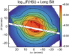 |
Fig. 23 Simulated footprint of the long slit (PA 79°) used by Fang & Liu (2011, 2013) in their deep spectroscopic study of NGC 7009 shown, in white, against the 10s Hβ image. The slit samples 14% of the total Hβ flux. The log F(Hβ) surface brightness contours are as in Fig. 7. |
Integrated NGC 7009 dereddened line ratios: observations and photoionization models.
9.1 1D photoionization model
Although the maps show the 2D appearance of line ratios, diagnostics and abundances, a simple 1D photoionization model is useful for quantifying how the 2D discrepancies affect conclusions about the structure of the nebula and the central star. Based on the dereddened emission line images (Sect. 5.1), an indicative basic set of line ratios for the integrated nebula was formed taking the Hβ flux within the contour of 7 × 10⁻¹⁷ ergs cm−2 s−1 per spaxel (surface brightness 2.8 × 10⁻¹⁸ ergs cm−2 s−1 arcsec−2, enclosing a total flux of 2.08 × 10⁻¹⁰ ergs cm−2 s−1). Table 3 lists the dereddened line fluxes relative to Hβ = 1.0; the dereddened fluxes from Fang & Liu (2011) are listed in Col. 4 for comparison.
As a starting basis, a spherical CLOUDY (version 17.01, Ferland et al. 2017) model was constructed starting with the set of abundances from Sabbadin et al. (2004) and a black body stellar atmosphere. A satisfactory model matching the line ratios in Table 3 could be found with a black body of 95 000 K, a constant density of 1600 cm−3, and inner and outer nebular radii of 0.0005 and 0.10 pc, respectively; dust was not included in the model. Column 5 of Table 3 lists the output CLOUDY relative fluxes; referred to as Model A. The footnote to the table lists the light element abundances; for elements not listed, abundances were taken from Sabbadin et al. (2004).
The stellar effective temperature is slightly higher than that determined by Sabbadin et al. (2004), and considerably higher than the value of 82 000 K found by Mendez et al. (1992) from a NLTE model atmosphere fit to the stellar lines profiles, but such a high value is required to match the He II/He I line ratios. The constant H density was lower than the electron density values from the integrated [S II] 6716.4/6730.8 Å and [Cl III]5517.7/5537.9 Å ratios of 3900 and 3300 cm−3, respectively, for an [S III] electron temperature of 9900 K, but no filling factor was included. The outer radius was restricted to ensure a density-bounded nebula to match the low ionization lines in particular.
A more elaborate model was constructed using an NLTE He-Ne model atmosphere from Rauch (2003; solar metallicity and log g = 5.0) and a spherical cylinder geometry with elongation to match the major axis length. The abundances of He, N, O and S were allowed to vary slightly (within 0.2 dex) of the values from Sabbadin et al. (2004) and Fang & Liu (2013). A stellar effective temperature of 98 000 K was used with a constant H density of 1000 cm−3, inner and outer radii of 0.0008 and 0.136, respectively, and a filling factor of 0.5; the abundances are listed in the footnote to Table 3. The quality of the match to the emitted spectrum (Table 3, Model B) is similar to Model A, except that the higher ionization gas is hotter as indicated by the stronger auroral [O III]4363.2 Å and [S III]6312.1 Å model line strengths. Model B could be used as a starting point for more elaborate 1D models to match the integrated spectrum and as the basis for 3D modelling.
10 Discussion
A few aspects of the rich set of MUSE data presented here are discussed: analysis of the spectra as opposed to the maps; comparisons among the various Te maps; the problem of abundance maps showing features of the ionization structures and how ICF’s might help to correct this; the prospects for photoionization modelling of these data.
10.1 Limited IFU analysis
The presentation and analysis has been restricted to mapping the emission lines and derived physical diagnostics at the native spatial resolution of 0.2″ × 0.2″, which samples the measured image quality of 0.5″–0.6″ well. This analysis clearly misses many diagnostically crucial weaker lines. Increasing the signal-to-noise per spatial element through various approaches, such as simple m × n binning of spaxels, summation of spaxels across morphological or ionization features or Voronoi tesselated binning to specified S/N (Sect. 6), offer approaches to measure weaker lines. In particular the ORL lines, with typical strengths ≪ 1% of F(Hβ) can be studied for how their properties relate to the CEL lines in identical spatial elements. The MUSE standard wavelength range provides access to the strongest N II, N III, C II and C III ORL lines but not to the strong O II M1 2p2 3p 4Do –2p23s 4P lines, which are however detectable with the MUSE extended mode (spectra to ~4650 Å). Of course, obtaining deeper spectra provides a more direct approach, but given the modest total exposure of 1200 s for the set of 120 s cubes, this route cannot be feasibly be pushed more than a factor ~10 (and NGC 7009 is among the highest average surface brightness PN accessible with MUSE). Not insubstantial are the problems associated with bright emission lines saturated in long exposures, which must be compensated by short unsaturated exposures, and can produce strong line wings around the brightest lines which hamper detection of surrounding faint lines.
Given the depth of the long slit spectrum data (detection of lines to 10−4 F(Hβ)) and detailedanalysis of Fang & Liu (2011, 2013), it is paramount to relate the physical conditions in these long slit data to those of the global nebula, in order to derive a truly nebula-integrated PN spectrum for comparison with observations of compact Galactic PNe, unresolved extra-Galactic PNe and the few nearby PNe with integrated spectra from slit-scanning observations (e.g. NGC 7027, Zhang et al. 2007). A follow-on paper will present a study of this cube-integrated spectrum and comparison with the results from the long slit study of Fang & Liu (2011, 2013).
10.2 Te diagnostics
Apart from the strikingly different morphology which is displayed in lines of differing ionization potential (Fig. 5), of most interest are the maps presenting the physical conditions, principally Te and Ne and extinction (the latter presented in Paper I). Here features show up with distinct properties (Figs. 7 and 8), such as the hotter inner shell (not unexpected on account of its strong He II emission), the higher density and temperature polar knots and ansae, features associated with the more filamentary knots K2 and K3 and the dust accumulation at the interface of the inner and outer shells. Of particular interest are the maps derived from H I and He I (Figs. 9, 10 and 11), which provide different views of the physical conditions prevailing in the bulk of the gas (Sect. 5.3), in comparison with the CEL diagnostics. The CEL and ORL density diagnostics present similar densities, with their mean values only differing by <1000 cm−3 (with [S II] lowest to the highest values from the fit to the H I Paschen lines). The CEL and ORL temperature diagnostics however differ strongly in value and morphology, with a range of 3000 K in their mean values (in decreasing magnitude – [S III], H I Paschen Jump to He I Te). It will be important for the abundance discrepancy factor (ADF) problem to compare ORL and CEL ionic abundances spaxel-wise. This comparison can however only be performed with MUSE for O, for which the extended spectral range is required.
Section 5.4 presents, to our knowledge, the first map of the temperature fluctuation parameter, t2, calculated however from [S III] Te in comparison to the “classical” method using [O III] Te (Peimbert 1971). The map shows the large scale structures with the inner shell framed by a rim of higher t2 with values of ~0.10. The other well-known features – knots K2 and K3 and the minor axis polar knots – notably show lower values, with t2 approaching zero, particularly over knots K1 and K4, where PJ Te is comparable to [S III] Te. Whilst t2 was formed from the difference of the [S III] and PJ Te and therefore typifies t2 for H+, it could just as well have been formulated in terms of the He I Te (Sect. 5.2.1) and another CEL temperature diagnostic, such as [Ar III]7135.8/5191.8 Å (Fang & Liu 2011), giving the He+ temperature fluctuations.
Rubin et al. (2002) from HST WF/PC2 imaging in narrow band filters covering the [O III]4363.2Å and [O III]5006.9Å lines computed the spatial variation of Te, the mean Te and fractional mean Te variation across the nebula (called  ). The resulting value of
  was very small, ≤0.01; much smaller than the value of the t2 temperature fluctuation determined here (Sect. 5.4). From STIS long slit spectroscopy, a mean [O III] Te of 10140 K and
  0.0035 were determined (Rubin et al. 2002). Comparing the map of [O III] Te (Rubin et al. 2002, Fig. 2) with [S III] Te (Fig. 8) shows similar aspects, such as the elevations on the minor axis, the lower value over the outer shell and even the depressions across the inner shell boundary; the [S III] Te map did not however extend to the outer halo where [O III] shows elevated values of Te. Rubin et al. (2002) calculated the mean Te and
  over an elliptical area of 560 arcsec2: over this area the mean [S III] Te and t2 values are 9130 K and 0.064 from the maps (Figs. 8 and 12, respectively).
  from [S III] Te over the same area yields a comparable value of 0.0011 to that from [O III] Te.
10.3 Towards a flat He/H
Unless the He abundance is indeed spatially structured, then the causes of the non-uniform He/H+ map (Fig. 20) must lie in the physical conditions applied in calculating the He++ and He+ /H+ ratios. Both Te and Ne in the He++ zone are notwell constrained and the [S III] and [Cl III] derived values were applied; these ions however sample a lower ionization medium (IP < 55 eV), while He++ exists at energies above 54 eV. The [Ar IV]4711.4/4740.2 Å ratio (just outside the MUSE standard wavelength coverage) samples Ne at energies between 40.7 and 59.8 eV and Fang & Liu (2011) determined an integrated Ne of 4890 cm−3, only slightly higher than the lower ionization species (see their Table 4).
Fang & Liu (2011) determined Te of 11000 K for the He++ zone from the 5694 Å free-bound Pfund series jump. In comparison, the 1D photoionization models of Sect. 9.1 predict area averaged Te(He++) of 12 800 K (Model A) and 15 600 K (Model B). Adopting the Fang & Liu (2011) Te (He++) value to determine He++/H+ makes an insignificant difference to the values in the map and does not alter the lack of flatness of the resulting total He map. Even increasing Te to the upper edge of the error bound quoted by Fang & Liu (2011), i.e., 13 000 K, does not change this situation since both He++ and H+ have very similar dependence of emissivity on Te. The 1D photoionization models (Table 3) predict that the contribution of He++ to total He/H+ is 23% (Model A) and 24% (Model B), so the He++/H+ contribution is a modest fraction of the total.
Higher ionization CEL Te diagnostic line ratios, such as [Ar V], or [Fe VI] and [Fe VII], would be required to probe the temperature in the He++ region; lines of these species are present in the tabulation of Fang & Liu (2011) but enough well-detected lines to determine Te are not available. Perhaps a dedicated spectroscopic search covering the regions with strongest He II could result in useful Ne and Te diagnostics for He++. If very hot gas (Te > 15 000 K) is present in the He++ region, then CEL cooling through the observed O, N and S emission is not efficient, so CEL Te (and Ne) diagnostics do not probe such hot gas effectively.
The results on the flatness of the He/H image imply that, in order to accurately determine abundances, it is important to use the value of Te appropriate to the emissivity for all the ionic species, and H+. This sounds obvious, but the enhanced He in the inner shell, which results by applying Te derived from the ratio of the He I lines to the He+ /H+ map, shows that this He+ temperature is not everywhere appropriate to producing a flat He/H result. The CLOUDY models (Sect. 9.1), by comparison, predict electron temperatures in the He+ zone of 9800 and 11 800 K (Models A and B, respectively), much higher than determined in Sect. 5.2.1. One possible approach to explore would be to use the assumption of flatness of the He/H map to determine Te as a variable in the He++ and He+ emission spaxels. Crude versions of this approach, such as scaling the [S III] Te map by a constant factor, were applied, but it did not prove possible to improve the flatness of the resulting He/H map beyond that shown in Fig. 20.
In computing the fraction of He++ vs. H+ in the inner shell, the fraction of H+ emitting in this zone also required; the latter is not available from a line-of-sight integrated map. Imaging with high enough velocity resolution offers a first approach to observational determination of the fraction of H+ in the He++ region, by apportioning the emission on the basis of the radial velocity (or perhaps from the line widths), as explored by Barlow et al. (2006) from slit spectroscopy. MUSE with its low resolution is not suitable for such a study, but FLAMES with higher spectral resolution modes (although a much smaller IFU) offers one approach (cf., Tsamis et al. 2008) as do high fidelity slit scanning and Fourier transform spectrometry.
10.4 ICFs
The peaks and boundaries in the map of He/H+ (Fig. 20) directly imply that the O/H+ map will not be flat since the O ICF schemes divide by some ratio of He/He+. Whilst flatness can be viewed as an ideal in a real nebula, without prior information that O abundance (usually considered not to be significantly enriched by the dredge-up episodes (cf., Richer 2007)) is spatially altering, the deviations from flatness at the positions of the boundaries in the ionization structures (inner/outer shell) suggest flaws in determining the physical conditions (extinction, temperature and density) or the ICF, or both. While the three ICF methods for O abundance yield very similar mean values (differing by 2.5%), the flatness of the O maps is highest for the Torres-Peimbert & Peimbert (1977) ICF and lowest for the Delgado-Inglada et al. (2014) one. With comparable MUSE data for other PNe, widely applicable solutions for spatial ICF’s can be investigated across a range of ionization conditions.
10.5 Potential for 3D modelling
The emission line and diagnostic maps presented provide observational inputs for 3D photoionization modelling, where the emission along all lines of sight across the whole nebula defined by the spaxels can be matched with the MUSE observations. As made clear in this presentation and the crudeness of 1D photoionization modelling (Sect. 9.1), IFU data of the depth and spatial coverage provided by MUSE demand the development of 3D models for explaining the interaction between emergent emission lines, diagnostics of extinction, Ne, Te and the ionic abundances. Codes such as MOCASSIN (Ercolano et al. 2003) and the multi-1D code, CLOUDY_3D (Morisset 2011), offer the desired approach. Gonçalves et al. (2006) already performed MOCASSIN modelling of NGC 7009 to match long slit and selected HST emission line images in a study of the outer knots K1 and K4. Inclusion of ultra-violet, infrared, mm/sub-mm and radio data, both resolved and unresolved, can lead to a comprehensive photoionization model considering the neutral and ionized gas, dust and molecular constituents, as performed by Otsuka et al. (2017) for NGC 6781.
11 Conclusions
The first detailed study of a planetary nebula with the MUSE spectrograph has been presented. The observations demonstrate the huge potential of this instrument for advancing optical spectroscopic studies of extended emission nebulae. Even with very short exposures, the high surface brightness of NGC 7009 allows a wealth of data to be exploited. The excellent image quality during the Science Verification observations enables quantitative spectroscopy at spatial resolution approaching that of HST.
The MUSE data on NGC 7009 have been presented in their reduced state as sets of flux maps, distinguished by sufficient signal-to-noise to be displayed and analysed in their native (0.2″ × 0.2″) spaxel form. A limited amount of analysis of these unbinned maps has been presented, such as observed line ratios (Sect. 4), Ne and Te maps (Sect. 5), ionic and total abundances (Sects. 7 and 8, respectively). The only exceptions to this approach were the presentation of Voronoi tesselated images in Hα and Hβ, in order to illustrate the potential for studies of the lower surface brightness halo (Sect. 6), and tabulation of an area-integrated spectrum for comparison to photoionization models (Sect. 9.1). These results by no means saturate therichness of the data cube.
In addition to images in a variety of emission lines from neutral species, such as [O I], to the high ionization potential species at good spatial resolution ([Mn V], 51.2 < ionization energy < 72.4 eV), line ratios have been used to derive ORL and CEL diagnostics of reddening, electron temperature and density. For the first time, maps of the differences in CEL and ORL Te have been derived, and correspondingly a map of t2 between a CEL and ORL temperature; they show considerable detail not limited to the differing ionization zones.
From the spatial coverage of physical conditions, derived parameters have been mapped, such as ionization fractions of some light elements. For He, the total abundance across the nebula could be determined; within 2.3% the He/H abundance is flat, but there are worrying signatures of the ionization structure still present, with remnants of the strongest He++ regions and the demarcation between inner and outer shells remaining. Data of the quality shown have the potential to provide general solutions for accurate abundance determination and derivation of ICF’s. But MUSE observations of a broader sample of PNe are required to develop such general conclusions that are applicable to nebulae of a range of ionization level, and abundance.
Acknowledgements
We sincerely thank the whole MUSE Science Verification team for achieving such a high level of data quality during this phase of the instrument testing. Peter Scicluna and Dave Stock are gratefully thanked for their contributions to the SV proposal. We thank Peter Storey for advice on possible recombination contribution to the [S III] 6312.1 Å emission, important for Te estimation. A.M.I. acknowledges support from the Spanish MINECO through project AYA2015-68217-P. M.L.L.-F. was supported by CNPq, Conselho Nacional de Desenvolvimento Científico e Tecnológico – Brazil, process number 248503/2013-8. We are very grateful to the referee for a deep review and for a multitude of suggestions, many of which were included into the revised version.
Appendix A Custom definition of Paschen Jump and calibration with Te
The map of electron temperature derived from the Paschen jump described in Sect. 5.2.2 and shown in Fig. 10 was derived using a custom method to measure the magnitude of the Paschen jump with respect to the P11 line tuned to MUSE spectra. This method was developed with the aim to produce a robust map of Paschen Jump Te over the many thousands of spaxel spectra where the jump could be reliably measured, without individually fitting the continuum jump as a function of Te and Ne at all spaxels. Figure A.1 shows a single spaxel spectrum from the 120 s MUSE cube over the bright inner shell (offsets Δ α = − 4.2″, Δ δ = + 2.6″ from the central star) in the region of the Paschen jump.
Continuum windows were selected based on the line-free sections of this typical spectrum, with the total continuum on the low and high wavelength sides of the jump (referred to simply as “blue” and “red”) not necessarily single consecutive sections. To the low wavelength side of the jump there is a line-free continuum section around 8050–8150 Å and this was selected; this window has the advantage that it contains no strong telluric absorption lines (there is a strong molecular absorption centred at around 8230 Å, extending to ~8180 Å).
At the MUSE (measured) resolution of about 2.8 Å, the higher Paschen lines are strongly blended (Fig. A.1) and so it proves challenging to define line-free continuum windows for estimation of the true nebula continuum to the long wavelength side of the jump. After some trials, three windows were chosen, 8550–8562, 8604–8640 and 8670–8695 Å, totalling 73 Å width; all but the bluest window suffer negligible telluric absorption. Although these windows are some hundreds of Å separated from the Paschen Jump, the theoretical nebular continuum can be calculated in these same windows to derive an expression for the definition of Paschen Jump with Te.
The continuum in a planetary nebula arises from four processes:
-
bound-free (b-f) emission from captures of free electrons by H+, He+ and He++ (b-f emission from atoms heavier than He is neglected as it makes a negligible contribution);
-
free-free (f-f), or Bremsstrahlung, emission from electrons being scattered by the nuclear charge of H+, He+ and He++;
-
two-photon (2-ν) gaseous continuum by radiative decay from the 22S – 12S levels of H+ and He++, which is forbidden by direct transition, and, much weaker, two photon decay from the 1s2s1− 1s2s3S states tothe ground state in He I (Drake 1969);
-
scattered continuum of non-gaseous origin, such as starlight scattered by dust (and electrons) and thermal emission of dust within the nebula.
The first three effects can be computed using well-known atomic recombination theory whilst the latter is object and geometry specific and is not amenable to direct computation. Since a map of the Paschen jump is produced, deviations in Te over the map can indicate non-gaseous scattering processes. A case in point is the central star: the Te map in Fig. 10shows very low values (<100 K) over the image of the central star since no attempt was made to subtract the stellar continuum from the total (stellar + nebular) continuum, the jump is thus dominated by the strong blue stellar continuum.
A.1 Computation of gaseous continuum emission
Schirmer (2016) provides a concise summary for computation of the nebular continuum together with a c routine to calculate the output spectrum (although this routine was not used for the computations described). Given its very minor contribution, the computation of He I 2-ν was neglected.
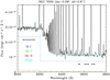 |
Fig. A.1 Dereddened spectrum of a single spaxel over the inner shell (offsets from position of central star indicated) around the wavelength of the H I Paschen Jump, showing the four continuum sections used to measure the magnitude of the jump. The calculated H I, He I and He II nebular continua are shown by coloured dotted lines. The spaxel has an extinction, c, of 0.186, an He+/H+ value of 0.094, an He++/H+ of 0.014, [Cl III] Ne 7520 cm−3 and a PJ Te of 7790 K. A continuum of 3.3 × 10⁻¹⁸ ergs cm−2 s−1 Å−1 had to be added to the summed theoretical continua of H I, He I and He II in order to match the total dereddened continuum flux. Given the displacement from the central star (of 5.0″), it is unclear if this is scattered continuum from the central star (either instrumental or intrinsic to the nebula), or instrument scattered light or residual sky background; the simplest option of a flat continuum was therefore chosen. |
b-f
The bound free continuum for H+, He+ and He++ has been calculated by Ercolano & Storey (2006) and coefficients are tabulated for an extensive set of transitions and for temperatures 100 ≤ T ≤ 105 K. The interpolation scheme for Te and frequency was used to calculate the b-f emission on a fine wavelength scale across the region of the Paschen jump.
f-f
The free-free emissivity of a hydrogenic ion of nuclear charge Z at a temperature T as a function of frequency (ν) is given by Brown & Mathews (1970) as
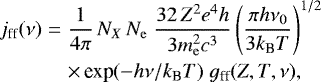 (A.1)
(A.1)
where NX and Ne are the ionic and electron number densities, hν0 is the ionization energy of hydrogen and the other symbols have their usual meaning (e the electron charge, c the speed of light, me the mass of the electron, h the Planck constant and kB the Boltzmann constant). gff is the thermally averaged mean free–free Gaunt factor which holds a quantum mechanical correction to the classical electron scattering formula. The non-relativistic mean free–free Gaunt factor has been recently presented by van Hoof et al. (2014) and tabulated as a function of scaled ionic energy and frequency (γ 2, u). The polynomial interpolation routine interpolate.F provided by van Hoof et al. (2014) was employed to calculate the Gaunt factor as a function of frequency and nuclear energy. There are very slight differences in the new computation of the mean free–free Gaunt factor from van Hoof et al. (2014) and the earlier tabulation by Hummer (1988) using the subroutine provided in Storey & Hummer (1991) for interpolation of the analytic approximation to gff(γ2, u): the differences amount to up to 0.2% for H I and 0.3% for He II over the wavelength range around the Paschen Jump and the range of Te encountered in PNe.
Fits to log10PJ = a − b ×log10Te for H I, He I and H ii.
Two-photon
The two-photon continuum of He I and He II peak at half the Lyman-α frequency (for H I at a wavelength of 1420 Å in a flux per Å spectrum; 608 Å for He II). The emissivity can be written as
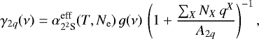 (A.2)
(A.2)
following Schirmer (2016). Here, g(ν) is the frequency dependence of the two-photon emission presented and fitted by Nussbaumer & Schmutz (1984) and  is the effective recombination coefficient of the upper (22 S) level. The evaluation of
  is given by interpolation as a function of Te and Ne in Tables 4 (for H I) and 5 (for He II) of Schirmer (2016; reproduced from Hummer & Storey 1987). g(ν) expresses the frequency dependence of the 2-photon spectrum in terms of the transition probability of the two photon transition of A2q = 8.2249 s−1 given by Nussbaumer & Schmutz (1984). The term in brackets expresses the effect of de-population of the 22 S level by means of angular momentum changing collisions, which can reduce the 2–ν flux at typical nebular densities; the collisional transition rate coefficient, qX (T, Ne) has been computed by Pengelly & Seaton (1964), but see Schirmer (2016) for a discussion. These corrections are implemented for H I and He II following Schirmer (2016).
A.2 Fitting the Paschen Jump vs. Te
The flux of the H I, He I and He II continua were calculated on a fine wavelength grid around the Paschen Jump and the mean flux in the window to the blue of the jump and the three windows to the red computed for a range of Te and at several Ne values. The emissivity of the H I P11 line for ratioing the Paschen Jump flux by that of an H I line was provided by the tables of Storey & Hummer (1995) for Case B. The variation of the defined jumps (blue–red continuum, employing means weighted by the number of pixels) ratioed by the P11 flux was then plotted for H I, He I and He II vs. Te at several Ne. Even in a log PJ (Å−1) vs. log Te plot, PJ can be multi-valued, particularly for the He I jump v Te at high Te (see Fig. A.2), so it was decided to fit the variation in defined Te ranges by simple fits following the form Te ∝PJ−n adopted by Fang & Liu (2011). However differing from Fang & Liu (2011), the fit of jump v Te was made independently for H I, He I and He II; the total (observed) jump was then formed as the sum of the three jumps for H I, He I and He II. This is more rigorous of the measurement situation and allows the possibility of different values of Te for the He+ and He++ emitting plasma to be included.
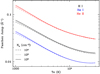 |
Fig. A.2 Variation of the jump around 8200 Å for H I, He I and He II as defined in the text with Te for several values of Ne (102, 103 and 104 cm−3) is shown in a log–log plot. |
Table A.1 lists the fits over three Te ranges chosen to retain an error on the fits of ≲300 K. These fits were then employed to produce the PJ Te map in Fig. 10 using the measured [Cl III] electron density to determine the fit of jump v Te to be applied within narrow ranges. Initially, the [S III] Te was employed to choose the fits range, then the resulting PJ Te map was used to position the fits; this process was iterated twice until the deviation on the Te values was ≲100 K, typically less than the fit errors. Estimates of errors on the PJ temperature were determined by Monte Carlo propagation of the error on the Paschen jump and the fit errors in K on the PJ vs. Te relations (Fig. A.2). Figure A.1 shows an example of the nebular continuum fit to an individual spaxel spectrum over the bright rim.
References
- Aleman, I., Ueta, T., Ladjal, D., et al. 2014, A&A, 566, A79 [NASA ADS] [CrossRef] [EDP Sciences] [Google Scholar]
- Ali, A., & Dopita, M. A. 2017, PASA, 34, e036 [NASA ADS] [CrossRef] [Google Scholar]
- Ali, A., Amer, M. A., Dopita, M. A., Vogt, F. P. A., & Basurah, H. M. 2015, A&A, 583, A83 [NASA ADS] [CrossRef] [EDP Sciences] [Google Scholar]
- Ali, A., Dopita, M. A., Basurah, H. M., et al. 2016, MNRAS, 462, 1393 [NASA ADS] [CrossRef] [Google Scholar]
- Bacon, R., Accardo, M., Adjali, L., et al. 2010, in Ground-Based and Airborne Instrumentation for Astronomy III, Proc. SPIE, 7735, 773508 [Google Scholar]
- Balick, B., Perinotto, M., Maccioni, A., Terzian, Y., & Hajian, A. 1994, ApJ, 424, 800 [NASA ADS] [CrossRef] [Google Scholar]
- Balick, B., Alexander, J., Hajian, A. R., et al. 1998, AJ, 116, 360 [NASA ADS] [CrossRef] [Google Scholar]
- Barlow, M. J., Hales, A. S., Storey, P. J., et al. 2006, in Planetary Nebulae in our Galaxy and Beyond, eds. M. J. Barlow & R. H. Méndez, IAU Symp., 234, 367 [NASA ADS] [CrossRef] [Google Scholar]
- Benjamin, R. A., Skillman, E. D., & Smits, D. P. 1999, ApJ, 514, 307 [NASA ADS] [CrossRef] [Google Scholar]
- Bohigas, J., Lopez, J. A., & Aguilar, L. 1994, A&A, 291, 595 [NASA ADS] [Google Scholar]
- Brown, R. L., & Mathews, W. G. 1970, ApJ, 160, 939 [NASA ADS] [CrossRef] [Google Scholar]
- Cappellari, M., & Copin, Y. 2003, MNRAS, 342, 345 [NASA ADS] [CrossRef] [Google Scholar]
- Corradi, R. L. M., Sánchez-Blázquez, P., Mellema, G., Gianmanco, C., & Schwarz, H. E. 2004, A&A, 417, 637 [NASA ADS] [CrossRef] [EDP Sciences] [Google Scholar]
- Delgado-Inglada, G., Morisset, C., & Stasińska, G. 2014, MNRAS, 440, 536 [NASA ADS] [CrossRef] [Google Scholar]
- Dopita, M. A., & Meatheringham, S. J. 1990, ApJ, 357, 140 [NASA ADS] [CrossRef] [Google Scholar]
- Drake, G. W. F. 1969, ApJ, 158, 1199 [NASA ADS] [CrossRef] [Google Scholar]
- Dufour, R. J., Kwitter, K. B., Shaw, R. A., et al. 2015, ApJ, 803, 23 [NASA ADS] [CrossRef] [Google Scholar]
- Ercolano, B., & Storey, P. J. 2006, MNRAS, 372, 1875 [NASA ADS] [CrossRef] [Google Scholar]
- Ercolano, B., Barlow, M. J., Storey, P. J., & Liu, X.-W. 2003, MNRAS, 340, 1136 [NASA ADS] [CrossRef] [Google Scholar]
- Etxaluze, M., Cernicharo, J., Goicoechea, J. R., et al. 2014, A&A, 566, A78 [NASA ADS] [CrossRef] [EDP Sciences] [Google Scholar]
- Fang, X., & Liu, X.-W. 2011, MNRAS, 415, 181 [NASA ADS] [CrossRef] [Google Scholar]
- Fang, X., & Liu, X.-W. 2013, MNRAS, 429, 2791 [NASA ADS] [CrossRef] [Google Scholar]
- Ferland, G. J., Chatzikos, M., Guzmán, F., et al. 2017, Rev. Mex. Astron. Astrofis., 53, 385 [NASA ADS] [Google Scholar]
- Freeman, M., Montez, Jr. R., Kastner, J. H., et al. 2014, ApJ, 794, 99 [NASA ADS] [CrossRef] [Google Scholar]
- Fried, D. L. 1966, J. Opt. Soc. Am., 56, 1372 [NASA ADS] [CrossRef] [Google Scholar]
- Gonçalves, D. R., Corradi, R. L. M., Mampaso, A., & Perinotto, M. 2003, ApJ, 597, 975 [NASA ADS] [CrossRef] [Google Scholar]
- Gonçalves, D. R., Ercolano, B., Carnero, A., Mampaso, A., & Corradi, R. L. M. 2006, MNRAS, 365, 1039 [NASA ADS] [CrossRef] [Google Scholar]
- Gray, M. D., Matsuura, M., & Zijlstra, A. A. 2012, MNRAS, 422, 955 [NASA ADS] [CrossRef] [Google Scholar]
- Guerrero, M. A., Chu, Y.-H., & Gruendl, R. A. 2000, ApJS, 129, 295 [NASA ADS] [CrossRef] [Google Scholar]
- Howarth, I. D. 1983, MNRAS, 203, 301 [NASA ADS] [CrossRef] [Google Scholar]
- Hummer, D. G. 1988, ApJ, 327, 477 [NASA ADS] [CrossRef] [Google Scholar]
- Hummer, D. G., & Storey, P. J. 1987, MNRAS, 224, 801 [NASA ADS] [CrossRef] [Google Scholar]
- Jacoby, G. H., & Ford, H. C. 1983, ApJ, 266, 298 [NASA ADS] [CrossRef] [Google Scholar]
- James, F., & Roos, M. 1975, Comput. Phys. Commun., 10, 343 [NASA ADS] [CrossRef] [PubMed] [Google Scholar]
- Kaler, J. B. 1979, ApJ, 228, 163 [NASA ADS] [CrossRef] [Google Scholar]
- Karakas, A. I., & Lattanzio, J. C. 2014, PASA, 31, e030 [NASA ADS] [CrossRef] [Google Scholar]
- Kastner, J. H., Montez, Jr. R., Balick, B., et al. 2012, AJ, 144, 58 [NASA ADS] [CrossRef] [EDP Sciences] [Google Scholar]
- Kingsburgh, R. L., & Barlow, M. J. 1994, MNRAS, 271, 257 [NASA ADS] [CrossRef] [Google Scholar]
- Lame, N. J., & Pogge, R. W. 1996, AJ, 111, 2320 [NASA ADS] [CrossRef] [Google Scholar]
- Leroy, J. L., Le Borgne, J. F., & Arnaud, J. 1986, A&A, 160, 171 [NASA ADS] [Google Scholar]
- Liu, X.-W., & Danziger, J. 1993, MNRAS, 263, 256 [NASA ADS] [CrossRef] [Google Scholar]
- Liu, X.-W., Barlow, M. J., Danziger, I. J., & Clegg, R. E. S. 1995a, MNRAS, 273, 47 [NASA ADS] [CrossRef] [Google Scholar]
- Liu, X.-W., Storey, P. J., Barlow, M. J., & Clegg, R. E. S. 1995b, MNRAS, 272, 369 [NASA ADS] [CrossRef] [Google Scholar]
- Liu, X.-W., Storey, P. J., Barlow, M. J., et al. 2000, MNRAS, 312, 585 [NASA ADS] [CrossRef] [Google Scholar]
- Liu, X.-W., Barlow, M. J., Zhang, Y., Bastin, R. J., & Storey, P. J. 2006, MNRAS, 368, 1959 [NASA ADS] [CrossRef] [Google Scholar]
- Luridiana, V., Morisset, C., & Shaw, R. A. 2015, A&A, 573, A42 [NASA ADS] [CrossRef] [EDP Sciences] [Google Scholar]
- Martin, T. B., Prunet, S., & Drissen, L. 2016, MNRAS, 463, 4223 [NASA ADS] [CrossRef] [Google Scholar]
- Matsuura, M., Speck, A. K., Smith, M. D., et al. 2007, MNRAS, 382, 1447 [NASA ADS] [CrossRef] [Google Scholar]
- Meaburn, J., & Walsh, J. R. 1981, Ap&SS, 78, 473 [NASA ADS] [CrossRef] [Google Scholar]
- Mendez, R. H., Kudritzki, R. P., & Herrero, A. 1992, A&A, 260, 329 [NASA ADS] [Google Scholar]
- Miller Bertolami, M. M. 2016, A&A, 588, A25 [NASA ADS] [CrossRef] [EDP Sciences] [Google Scholar]
- Monreal-Ibero, A., Roth, M. M., Schönberner, D., Steffen, M., & Böhm, P. 2005, ApJ, 628, L139 [NASA ADS] [CrossRef] [Google Scholar]
- Monreal-Ibero, A., Roth, M. M., Schönberner, D., Steffen, M., & Böhm, P. 2006, New Astron. Rev., 50, 426 [NASA ADS] [CrossRef] [Google Scholar]
- Monreal-Ibero, A., Walsh, J. R., Westmoquette, M. S., & Vílchez, J. M. 2013, A&A, 553, A57 [NASA ADS] [CrossRef] [EDP Sciences] [Google Scholar]
- Monteiro, H., Gonçalves, D. R., Leal-Ferreira, M. L., & Corradi, R. L. M. 2013, A&A, 560, A102 [NASA ADS] [CrossRef] [EDP Sciences] [Google Scholar]
- Montez, Jr. R., Kastner, J. H., Balick, B., et al. 2015, ApJ, 800, 8 [NASA ADS] [CrossRef] [Google Scholar]
- Moreno-Corral, M., de La Fuente, E., & Gutiérrez, F. 1998, Rev. Mex. Astron. Astrofis., 34, 117 [NASA ADS] [Google Scholar]
- Morisset, C. 2011, Cloudy_3D: Quick Pseudo-3D Photoionization Code, Astrophysics Source Code Library [Google Scholar]
- Morisset, C. 2017, in Planetary Nebulae: Multi-Wavelength Probes of Stellar and Galactic Evolution, eds. X. Liu, L. Stanghellini, & A. Karakas, IAU Symp., 323, 43 [NASA ADS] [Google Scholar]
- Noll, S., Kausch, W., Barden, M., et al. 2012, A&A, 543, A92 [NASA ADS] [CrossRef] [EDP Sciences] [Google Scholar]
- Nussbaumer, H., & Schmutz, W. 1984, A&A, 138, 495 [NASA ADS] [Google Scholar]
- Otsuka, M., Ueta, T., van Hoof, P. A. M., et al. 2017, ApJS, 231, 22 [NASA ADS] [CrossRef] [Google Scholar]
- Peimbert, M. 1967, ApJ, 150, 825 [NASA ADS] [CrossRef] [Google Scholar]
- Peimbert, M. 1971, Boletin de los Observatorios Tonantzintla y Tacubaya, 6, 29 [NASA ADS] [Google Scholar]
- Peimbert, M., & Costero, R. 1969, Boletin de los Observatorios Tonantzintla y Tacubaya, 5, 3 [Google Scholar]
- Peimbert, M., & Torres-Peimbert, S. 1971a, Boletin de los Observatorios Tonantzintla y Tacubaya, 6, 21 [NASA ADS] [Google Scholar]
- Peimbert, M., & Torres-Peimbert, S. 1971b, ApJ, 168, 413 [NASA ADS] [CrossRef] [Google Scholar]
- Pengelly, R. M., & Seaton, M. J. 1964, MNRAS, 127, 165 [NASA ADS] [CrossRef] [Google Scholar]
- Persi, P., Cesarsky, D., Marenzi, A. R., et al. 1999, A&A, 351, 201 [NASA ADS] [Google Scholar]
- Phillips, J. P., Cuesta, L. C., & Ramos-Larios, G. 2010, MNRAS, 409, 881 [NASA ADS] [CrossRef] [Google Scholar]
- Pitrou, C., Coc, A., Uzan, J.-P., & Vangioni, E. 2018, Phys. Rep., 4, 005 [Google Scholar]
- Porter, R. L., Ferland, G. J., Storey, P. J., & Detisch, M. J. 2012, MNRAS, 425, L28 [NASA ADS] [Google Scholar]
- Porter, R. L., Ferland, G. J., Storey, P. J., & Detisch, M. J. 2013, MNRAS, 433, L89 [NASA ADS] [CrossRef] [Google Scholar]
- Rauch, T. 2003, A&A, 403, 709 [NASA ADS] [CrossRef] [EDP Sciences] [Google Scholar]
- Reay, N. K., Atherton, P. D., & Taylor, K. 1983, MNRAS, 203, 1079 [NASA ADS] [CrossRef] [Google Scholar]
- Reay, N. K., Atherton, P. D., & Taylor, K. 1984, MNRAS, 206, 71 [NASA ADS] [CrossRef] [Google Scholar]
- Richard, J., Bacon, R., & Vernet, J. 2017, MUSE User Manual. Issue 8.1 (ESO) [Google Scholar]
- Richer, M. G. 2007, J. Korean Astron. Soc., 40, 183 [NASA ADS] [CrossRef] [Google Scholar]
- Richer, M. G., McCall, M. L., & Martin, P. G. 1991, ApJ, 377, 210 [NASA ADS] [CrossRef] [Google Scholar]
- Robbins, R. R. 1968, ApJ, 151, 511 [NASA ADS] [CrossRef] [Google Scholar]
- Rubin, R. H. 1986, ApJ, 309, 334 [NASA ADS] [CrossRef] [Google Scholar]
- Rubin, R. H., Bhatt, N. J., Dufour, R. J., et al. 2002, MNRAS, 334, 777 [NASA ADS] [CrossRef] [Google Scholar]
- Sabbadin, F., Turatto, M., Cappellaro, E., Benetti, S., & Ragazzoni, R. 2004, A&A, 416, 955 [NASA ADS] [CrossRef] [EDP Sciences] [Google Scholar]
- Sandin, C. 2014, A&A, 567, A97 [NASA ADS] [CrossRef] [EDP Sciences] [Google Scholar]
- Sandin, C., Schönberner, D., Roth, M. M., et al. 2008, A&A, 486, 545 [NASA ADS] [CrossRef] [EDP Sciences] [Google Scholar]
- Schirmer, M. 2016, PASP, 128, 114001 [NASA ADS] [CrossRef] [Google Scholar]
- Schönberner, D., Jacob, R., Lehmann, H., et al. 2014, Astron. Nachr., 335, 378 [NASA ADS] [CrossRef] [Google Scholar]
- Seaton, M. J. 1979, MNRAS, 187, 73P [NASA ADS] [CrossRef] [Google Scholar]
- Storey, P. J., & Hummer, D. G. 1991, Comp. Phys. Comm, 66, 129 [Google Scholar]
- Storey, P. J., & Hummer, D. G. 1995, MNRAS, 272, 41 [NASA ADS] [CrossRef] [Google Scholar]
- Taylor, K., & Atherton, P. D. 1980, MNRAS, 191, 675 [NASA ADS] [Google Scholar]
- Torres-Peimbert, S., & Peimbert, M. 1977, Rev. Mex. Astron. Astrofis., 2, 181 [NASA ADS] [Google Scholar]
- Tsamis, Y. G., Walsh, J. R., Péquignot, D., et al. 2008, MNRAS, 386, 22 [NASA ADS] [CrossRef] [Google Scholar]
- Ueta, T., Ladjal, D., Exter, K. M., et al. 2014, A&A, 565, A36 [NASA ADS] [CrossRef] [EDP Sciences] [Google Scholar]
- van Hoof, P. A. M., Williams, R. J. R., Volk, K., et al. 2014, MNRAS, 444, 420 [NASA ADS] [CrossRef] [Google Scholar]
- Walsh, J. R., & Clegg, R. E. S. 1994, MNRAS, 268, L41 [NASA ADS] [CrossRef] [Google Scholar]
- Walsh, J. R., Monreal-Ibero, A., Barlow, M. J., et al. 2016, A&A, 588, A106 [NASA ADS] [CrossRef] [EDP Sciences] [Google Scholar]
- Weilbacher, P. M., Streicher, O., Urrutia, T., et al. 2014, in Astronomical Data Analysis Software and Systems XXIII, eds. N. Manset, & P. Forshay, ASP Conf. Ser., 485, 451 [NASA ADS] [Google Scholar]
- Weilbacher, P. M., Monreal-Ibero, A., Kollatschny, W., et al. 2015, A&A, 582, A114 [NASA ADS] [CrossRef] [EDP Sciences] [Google Scholar]
- Zhang, Y., Liu, X.-W., Wesson, R., et al. 2004, MNRAS, 351, 935 [NASA ADS] [CrossRef] [Google Scholar]
- Zhang, Y., Liu, X.-W., Liu, Y., & Rubin, R. H. 2005, MNRAS, 358, 457 [NASA ADS] [CrossRef] [Google Scholar]
- Zhang, Y., Liu, X.-W., Luo, S.-G., Péquignot, D., & Barlow, M. J. 2007, A&A, 472, 555 [NASA ADS] [CrossRef] [EDP Sciences] [Google Scholar]
IRAF is distributed by the National Optical Astronomy Observatories, which are operated by the Association of Universities for Research in Astronomy, Inc., under cooperative agreement with the National Science Foundation.
The [O II]7330.7 Å line (from the 2 P3∕2–2D3∕2 transition) has a much higher collisional de-excitation density (5.1 × 106 cm−3 at 10 000 K) compared to the [N II]6583.5 Å (1D2–3P2) line (9.0 × 104 cm−3), so the [O II] image may be influenced by the presence of higher density low ionization gas over the inner shell.
The [S III]6312.1 Å line can also suffer from recombination contribution from S+++ in the same way as [N II]. However, there are currently no calculations of the recombination contribution to the [S III] 1S0 level available. Given that the [S III] Te appears to be lower than [O III] Te (Fang & Liu 2011), in contrast to [N II] Te over the inner shell, suggests that any non-collisional component to [S III]6312.1 Å emission cannot be very large, but obviously this cannot be confirmed.
This assumption was found to be valid within ~10% by running CLOUDY models matching the central star parameters and nebula abundances (see Sect. 9.1).
All Tables
Integrated NGC 7009 dereddened line ratios: observations and photoionization models.
All Figures
|
Fig. 1 Sky mask for the PA 33° exposures. The dark areas (green) are masked as non-sky (nebula and stars). |
| In the text | |
|
Fig. 2 Images of NGC 7009 in the O emission lines: O0 (from the [O I]6300.3 Å line, 120 s cube), O+ (from the [O II]7330.2 Å line, 120 s cube) and O++ (from the [Oiii]4958.9 Å 10 s cube). |
| In the text | |
|
Fig. 3 Images of NGC 7009 in H and He emission line images: H+ as sampled by Balmer 4–2 Hβ 4861.3 Å fromboth the 10 s and 120 s cubes; He+ from the triplet (2P 3d – 3D 2s) He I 5875.6 Å line (120 s cube); and He++ from He II 5411.5 Å 7–4 line (120 s cube). |
| In the text | |
|
Fig. 4 Images if NGC 7009 in Ne and Te sensitive emission lines: [S II]6716.4 Å line for Ne; [Cl III]5537.9Å for Ne; [N II]6583.5 Å for Te; and [S III]9068.6 Å for Te. On the [N II] image the ansae are indicated and the designation of the various knots from Gonçalves et al. (2003). |
| In the text | |
|
Fig. 5 Simple observed emission line ratio images (linear scale, × 100) with respect to an H line for NGC 7009, ordered by decreasing ionization potential of the nominator image: [Mn V]6393.5Å/Hβ; He II 5411.5 Å/Hβ; [O III]4958.9 Å/Hβ; He I 5875.6 Å/Hα; [O II]7330.2 Å/Hα; [N II]6583.5 Å/Hα; [S II]6730.8 Å/Hα and [O I]6300.3 Å/Hα. The 3× 3-σ clipped means on the signal-to-error above 3× the error on the ratio are: 8, 35, 47, 60, 26, 41, 34 and 29, respectively. |
| In the text | |
|
Fig. 5 continued. |
| In the text | |
|
Fig. 6 Maps of two detected optical recombination lines are shown. Left panel: N II V3 multiplet 3p 3 D – 3s 3 P line at 5679.6 Å. Right panel: C II 3d 2D–3p 2P line at 7231.3 Å. |
| In the text | |
|
Fig. 7 Maps of Ne determinedfrom [S II] (left panel) and [Cl III] (right panel). The contours correspond to the observed log F(H β) image shownin Fig. 3 (left panel), with contours set at log10 F(H β) surface brightness (ergs cm−2 s−1 arcsec−2) from −15.0 to −11.8 in steps of +0.4. The electrondensities for collisional de-excitation of the [S II] and [Cl III] 2D3∕2 levels for these diagnostics are 3.1 × 10³ and 2.4 × 104 cm−3 at 104 K, respectively. The simple means on the signal-to-error value over the two Ne maps are 6 and 4, respectively. |
| In the text | |
|
Fig. 8 Maps of Te determined from [N II] (left panel) and [S III] (right panel). The elevated values in the central region for the [N II] Te are assumed to be caused by the contribution of N++ recombination to the [N II]5754.6 Å line; see text for a consideration. The log F(H β) surface brightness contours are as in Fig. 7. The simple means on the signal-to-error value over the two Te maps are 52and 21, respectively. |
| In the text | |
|
Fig. 9 The map of He+ Te (left panel)derived from the ratio of the He I singlet lines 7281.4/6678.2 Å. The mean signal-to-error value is 11. Right panel: difference map between the [S III] and He I Te maps. The log F(Hβ) surface brightness contours are as in Fig. 7. |
| In the text | |
|
Fig. 10 Map of Te derived from the magnitude of the Paschen continuum jump at 8250 Å ratioed by the dereddened H I Paschen 11 (8862.8 Å) emission line strength. Initial estimates of Te and Ne from the [S III] and [Cl III] ratio maps (Sect. 5.1) were applied, followed by two iterations with the derived Te map from the Paschen Jump. See text for details. The low Te values over the central star are not representative and arise from the strong stellar continuum. The log F(H β) surface brightness contours are as in Fig. 7. The mean signal-to-error is 13. |
| In the text | |
|
Fig. 11 Map of Ne derived by comparing the strengths of the higher Paschen lines (P15 – P26) with the Case B predictions, adopting Te values provided by the [S III] ratio. The log F(Hβ) surface brightness contours are as in Fig. 7. The mean signal-to-error is 2. |
| In the text | |
|
Fig. 12 Maps of the average temperature (T0, left panel) and the temperature fluctuation parameter (t2, right panel) determined from the [S III] and the Paschen Jump Te maps. The log F(Hβ) surface brightness contours are as in Fig. 7. The mean signal-to-error over the T0 map is 45 and for the t2 map is 15. |
| In the text | |
|
Fig. 13 Left panel: Voronoi tesselated version of the 120 s Hβ emission line image, in a log display showing the adaptive bins. Right panel: extinction map, c(Hβ), for the Voronoi tesselated images based on the ratio of the 120 s Hβ image and the 10 s Hα images. |
| In the text | |
|
Fig. 14 τ(3888.6 Å) from the ratio of He I 7065.7 Å and 6678.2 Å lines, calculated with the He I Te map and a ratio of expansion velocity to thermal velocity for the nebula of 5. The log F(H β) surface brightness contours are as in Fig. 7. |
| In the text | |
|
Fig. 15 Map of He+/H+ determined from the He I 6678.2 Å and Hβ dereddened emission line maps with the He+ Te and [S III] Te maps, respectively, and the single [Cl III] Ne map. The log F(Hβ) surface brightness contours are as in Fig. 7. The mean signal-to-error ratio on He+ /H+ is ~14. |
| In the text | |
|
Fig. 16 Map of He++/H+ using the [S III] Te and the [Cl III] Ne maps. The log F(Hβ) surface brightness contours are as in Fig. 7. The mean value of signal-to-error is 12. |
| In the text | |
|
Fig. 17 Maps of O0, O+ and O++/H+ ionic abundances. The log F(Hβ) surface brightness contours are as in Fig. 7. The mean signal-to-error values on O0, O+ and O++/H+ are 12, 21 and 13, respectively. |
| In the text | |
|
Fig. 18 Map of N+/H+ from the CEL [N II] lines (left panel) and for N++/H+ from the N ii5679.6 Å ORL line (right panel). The log F(Hβ) surface brightness contours are as in Fig. 7. The mean values of signal-to-error are 15 and 5, respectively. |
| In the text | |
|
Fig. 19 Maps of S+ and S++, Cl++ and Cl+++ and Ar++ and Ar+++/H+ ionic abundances. The log F(Hβ) surface brightness contours are as in Fig. 7. |
| In the text | |
|
Fig. 20 Sum of He+/H+ and He++/H+ using the [S III] Te and [Cl III] Ne maps for He+/H+ and He++/H+ computation. The log F(Hβ) surface brightness contours are as in Fig. 7. |
| In the text | |
|
Fig. 21 Maps of total O/H+ abundance for three ionization correction factors adjusting for the presence of O+++. Left: the ’classical’ scheme of Torres-Peimbert & Peimbert (1977); centre: the corrected classical ICF advocated by Kingsburgh & Barlow (1994); right: the model-based approach of Delgado-Inglada et al. (2014). The log F(Hβ) surface brightness contours are as in Fig. 7. |
| In the text | |
|
Fig. 22 Map of the N/O abundance based on the N+/H+ and O+ /H+ maps (Figs. 18 and 17, respectively). The log F(H β) surface brightness contours are as in Fig. 7. The mean value of signal-to-error is 13. |
| In the text | |
|
Fig. 23 Simulated footprint of the long slit (PA 79°) used by Fang & Liu (2011, 2013) in their deep spectroscopic study of NGC 7009 shown, in white, against the 10s Hβ image. The slit samples 14% of the total Hβ flux. The log F(Hβ) surface brightness contours are as in Fig. 7. |
| In the text | |
|
Fig. A.1 Dereddened spectrum of a single spaxel over the inner shell (offsets from position of central star indicated) around the wavelength of the H I Paschen Jump, showing the four continuum sections used to measure the magnitude of the jump. The calculated H I, He I and He II nebular continua are shown by coloured dotted lines. The spaxel has an extinction, c, of 0.186, an He+/H+ value of 0.094, an He++/H+ of 0.014, [Cl III] Ne 7520 cm−3 and a PJ Te of 7790 K. A continuum of 3.3 × 10⁻¹⁸ ergs cm−2 s−1 Å−1 had to be added to the summed theoretical continua of H I, He I and He II in order to match the total dereddened continuum flux. Given the displacement from the central star (of 5.0″), it is unclear if this is scattered continuum from the central star (either instrumental or intrinsic to the nebula), or instrument scattered light or residual sky background; the simplest option of a flat continuum was therefore chosen. |
| In the text | |
|
Fig. A.2 Variation of the jump around 8200 Å for H I, He I and He II as defined in the text with Te for several values of Ne (102, 103 and 104 cm−3) is shown in a log–log plot. |
| In the text | |
Current usage metrics show cumulative count of Article Views (full-text article views including HTML views, PDF and ePub downloads, according to the available data) and Abstracts Views on Vision4Press platform.
Data correspond to usage on the plateform after 2015. The current usage metrics is available 48-96 hours after online publication and is updated daily on week days.
Initial download of the metrics may take a while.