| Issue |
A&A
Volume 691, November 2024
|
|
|---|---|---|
| Article Number | A334 | |
| Number of page(s) | 12 | |
| Section | Cosmology (including clusters of galaxies) | |
| DOI | https://doi.org/10.1051/0004-6361/202349095 | |
| Published online | 26 November 2024 | |
Filaments in and between galaxy clusters at low and mid-frequency with the SKA
1
INAF – Osservatorio Astronomico di Cagliari,
Via della Scienza 5,
09047
Selargius
(CA),
Italy
2
INAF – Istituto di Radioastronomia,
Via P. Gobetti 101,
40129
Bologna,
Italy
3
Theoretical Astrophysics, Los Alamos National Laboratory,
Los Alamos,
NM,
USA
4
Sapienza – University of Rome – Physics Department,
Piazzale Aldo Moro 5,
00185
Rome,
Italy
5
Max Planck Institute for Astrophysics,
Karl-Schwarzschildstr. 1,
85741
Garching,
Germany
★ Corresponding author; This email address is being protected from spambots. You need JavaScript enabled to view it.
Received:
24
December
2023
Accepted:
25
September
2024
Abstract
Context. Understanding the magnetised Universe is a major challenge in modern astrophysics, and cosmic magnetism has been acknowledged as one of the key scientific drivers of the most ambitious radio instrument ever planned, the Square Kilometre Array.
Aims. With this work, we aim to investigate the potential of the Square Kilometre Array and its precursors and pathfinders in the study of magnetic fields in galaxy clusters and filaments through diffuse synchrotron radio emission. Galaxy clusters and filaments of the cosmic web are indeed unique laboratories in which to investigate turbulent fluid motions and large-scale magnetic fields in action, and much of what is known about magnetic fields in galaxy clusters comes from sensitive radio observations.
Methods. Based on cosmological magneto-hydrodynamic simulations, we predict radio properties (total intensity and polarisation) of a pair of galaxy clusters connected by a cosmic-web filament.
Results. We use our theoretical expectations to explore the potential of polarimetric observations to study large-scale structure magnetic fields in the frequency ranges 50–350 MHz and 950–1760 MHz. We also present predictions for galaxy cluster polarimetric observations with the Square Kilometre Array precursors and pathfinders, such as the LOw frequency ARray 2.0 and the MeerKAT+ telescope.
Conclusions. Our findings point out that polarisation observations are particularly powerful for the study of large-scale magnetic fields, since they are not significantly affected by confusion noise. The unprecedented sensitivity and spatial resolution of the intermediatefrequency radio telescopes make them the favourite instruments for the study of these sources through polarimetric data, potentially allowing us to understand if the energy density of relativistic electrons is in equipartition with the magnetic field or rather coupled with the thermal gas density. Our results show that low-frequency instruments also represent a precious tool to study diffuse synchrotron emission in total intensity and polarisation.
Key words: acceleration of particles / magnetic fields / polarization / radiation mechanisms: non-thermal / galaxies: clusters: intracluster medium / large-scale structure of Universe
© The Authors 2024
 Open Access article, published by EDP Sciences, under the terms of the Creative Commons Attribution License (https://creativecommons.org/licenses/by/4.0), which permits unrestricted use, distribution, and reproduction in any medium, provided the original work is properly cited.
This article is published in open access under the Subscribe to Open model. This email address is being protected from spambots. You need JavaScript enabled to view it. to support open access publication.
1 Introduction
Turbulence and shock waves in merging galaxy clusters are likely to (re-)accelerate a pre-existing electron population embedded in an ~μG intracluster magnetic field to ultra-relativistic energies (γ ≳ 104). These non-thermal components can be observed in the radio domain in the form of faint (~0.1 μJy/arcsec2 at 1.4 GHz) diffuse steep-spectrum (Sv ∝ v−α, with α ≈ 1–1.3) synchrotron sources, called radio halos and relics, located, respectively, at the centre and periphery of a fraction of merging galaxy clusters. Typically, radio halos show a correlation between the radio power and the cluster X-ray luminosity and mass, and a smooth and regular morphology similar to the distribution of the thermal plasma. The radio relics also show a correlation between their radio power and the cluster X-ray luminosity and are generally characterised by an elongated morphology (see, e.g., the reviews by Feretti et al. 2012, van Weeren et al. 2019 and references therein).
While radio relics show strong fractional polarisation (e.g., Clarke & Enßlin 2006; Bonafede et al. 2009a; van Weeren et al. 2010, 2012; Loi et al. 2017, 2020; Rajpurohit et al. 2020), only three radio halos (Govoni et al. 2005; Bonafede et al. 2009b; Girardi et al. 2016) show polarised emission, and for one of them polarisation has been detected on larger scales than the total intensity (i.e., about R500 Vacca et al. 2022). Thanks to the high sensitivity and high spatial and spectral resolution, future Square Kilometre Array (SKA) data should enable one to observe radio halo polarised emission in a larger number of galaxy clusters (Govoni et al. 2013). Stronger constraints on cluster magnetic fields are expected when polarised emission from both radio halos and background radio galaxies is detected (e.g., Loi et al. 2019a). Indeed, the detection of polarised emission of these extended diffuse sources combined with Faraday rotation of background and embedded radio galaxies permit us to better investigate the intracluster magnetic field power spectrum. The study of the intracluster magnetic field through the combinations of these two observables has to date been performed in only two cases (e.g., Govoni et al. 2006; Vacca et al. 2010). A detailed study of the magnetic field properties through the polarimetric properties of radio halos or background radio galaxies, or both, has been conducted in only a limited sample of galaxy clusters. Current studies reveal that magnetic fields are characterised by central strengths of a few microGauss in merging galaxy clusters and up a few tens of microGauss in relaxed cool core clusters. Indications of a connection between the magnetic field strength and the thermal gas density at the centre of the cluster have been found (Govoni et al. 2017).
Beyond galaxy clusters, the Planck satellite (Planck Collaboration Int. VIII 2013; Planck Collaboration XXII 2016) revealed the Sunyaev Zeldovich (SZ) effect associated with a bridge of plasma connecting two galaxy clusters, A399 and A401. By complementing Planck observations with Atacama Cosmology Telescope (ACT) data, Hincks et al. (2022) found that the size of the bridge is much more extended (~12 Mpc) than the projected separation in the plane of the sky (~3 Mpc). In this system, synchrotron emission has been detected through the observation of a double radio halo in the two clusters (Murgia et al. 2010) and, for the first time, along the filament of matter connecting them (Govoni et al. 2019), and as a consequence the presence of non-negligible magnetic fields has been inferred. Another case of diffuse emission between two galaxy clusters was later confirmed in the system A1758 (Botteon et al. 2020), as well as a bridge connecting a cluster and a group in the Shapley Supercluster (Venturi et al. 2022). From a statistical point of view, detections still waiting for confirmation have been presented in Vacca et al. (2018). An analysis based on stacking techniques revealed an average magnetic field strength of 0.03 μG ≤ B ≤ 0.06 μG along cosmic filaments from total intensity observations (Vernstrom et al. 2021), as well as polarised emission associated with accretion shocks from the cosmic web (Vernstrom et al. 2023).
Simulations of pairs of galaxy clusters and the filament connecting them are essential to explore the potential of the SKA telescope, its precursors, and pathfinders to study the magnetisation of the large-scale-structure of the Universe with polarimetric observations. In this paper, we present synthetic images of a galaxy cluster pair similar to A399–A401, as is expected with LOw Frequency ARray (LOFAR 2.0), SKA-LOW, MeerKAT+, and SKA-MID. Properties of magnetic fields in low-density environments such as filaments mainly reflect the pristine magnetic field strength and structure in the Universe, and therefore their study is of paramount importance to shed light on the origin of cosmic magnetism.
The paper is organised as follows. In Sect. 2, we present magneto-hydrodynamic (MHD) simulations (thermal density, magnetic field, and temperature) of a pair of colliding galaxy clusters, and we outline their similarity with the A399–A401 system. In Sect. 3, we present synthetic X-ray, SZ, and radio images of the simulated system and how these synthetic images compare to available literature data. In Sect. 4, we present expectations of the SKA telescope, its precursor, and pathfinders, respectively, at mid- and low frequencies in total intensity and polarisation under the equipartition assumption between the magnetic field and the relativistic electrons and in the case that the relativistic electron distribution has an energy density equal to 0.3 percent of the thermal one. Finally, in Sect. 5, we draw our conclusions.
In the following, we use a ΛCDM cosmology with H0 = 72 km/s/Mpc, Ω0 = 0.258, and ΩΛ = 0.742. We present this simulated galaxy cluster pair as being observed at a redshift of z = 0.073, the same as the redshift of A399–A401. With this cosmology, at this distance, 1″ corresponds to 1.354 kpc.
2 Magneto-hydrodynamic simulations
The cosmological MHD simulation presented here is obtained with the ENZO code (Collins et al. 2010) with adaptive mesh refinement developed by the group of Hui Li at Los Alamos National Laboratories, USA. The simulation runs from z = 30 to z = 0 and follows the evolution of the dark matter, baryonic matter, and magnetic fields. It uses an adiabatic equation of state with a specific heat ratio, Γ = 5/3, and does not include heating and cooling physics or chemical reactions. The magnetic fields are injected by active galactic nuclei at z = 2–3 and then amplified and spread over megaparsec scales during the late stages of the merger (Xu et al. 2012). A description of how the magnetic fields are injected is given in Xu et al. (2008, 2009). For the purposes of this work, a single snapshot of the MHD simulation is used. This snapshot of the simulation captures a pair of galaxy clusters and the filament connecting them immediately before the merging process begins. The output of the simulation consists of a set of three-dimensional cubes of ≈(6.42 Mpc)3 with a cell size of ≈10.7 kpc containing the intracluster medium (ICM) physical parameters: temperature, thermal plasma density, and magnetic field. Some characteristics of the simulated system are summarised in Table 1. From the values in this table, we can compute the central magnetic to thermal gas energy density ratios, which are 0.2, 0.5, and 0.4%, respectively, for C1, C2, and the filament. We note that Xu et al. (2010) showed that the distribution of the resulting intracluster magnetic field at low redshifts is not very sensitive to the exact injection redshifts and to the injected magnetic energies. Moreover, the purpose of this work is not to shed light on the magnetic field strength or on the magneto-genesis process, but rather on the capabilities of the future radio instrumentation to detect in total intensity and polarisation systems with properties similar to those currently known.
In Fig. 1, we show in the top panels a central plane extracted from the cubes of the simulated thermal gas density, total magnetic field, and temperature of two merging galaxy clusters. In the bottom panels, we show the spherically averaged radial profiles computed on the simulated cubes of the thermal gas density, total magnetic field, and temperature of the same system. These profiles were calculated in concentric shells with a one-voxel width and starting from the clusters’ centres, defined as the thermal gas density peak in three dimensions. The three-dimensional distance between the two clusters is 3 Mpc. We chose a midplane slice of that simulation passing close to the centres of both clusters, as can be inferred from Fig. 1. The two galaxy clusters are connected by a magnetised filament of matter with a higher temperature than the surroundings, indicating that the galaxy clusters are approaching each other. When spherically averaging the thermal gas density, magnetic field, and temperature of the system, the estimates of these quantities get contaminated by the filament volume. Therefore, in the spherically averaged profiles we indicate with a shaded grey region the radius above which the profiles must be taken with caution because the filament properties affect the profiles. Moreover, we stress that the properties inferred from the spherically averaged radial profiles are not representative of the physical conditions in the filament, because they are derived by azimuthally averaging over a region of space that also includes the medium around the clusters.
It is interesting to compare the intracluster magnetic field of our simulations to that of real galaxy clusters, for which a detailed estimate is present in the literature. In the left panel of Fig. 2, we show a plot of the central magnetic field strength, ⟨B0⟩1. versus the central electron density, n0, while in the right panel of Fig. 2 we show a plot of ⟨B0⟩ versus the mean cluster temperature, T. These values have been taken from Govoni et al. (2017) and have been converted to our cosmology. In general, fainter central magnetic fields seem to be present in less dense galaxy clusters. As is noted in Govoni et al. (2017), although the cluster sample is still rather small, we note that there is a hint of a positive trend between ⟨B0⟩ and n0 measured among different clusters, while no correlation seems to be present between the central magnetic field and the mean cluster temperature. In the figures, we plot the values of the magnetic field, thermal gas density, and temperature at the centre of the simulated clusters C1 and C2, and in the middle point of the filament. However, the temperature of the simulated clusters is rather constant, as is shown by the bottom right panel in Fig. 1. The simulated galaxy clusters are characterised by a weak central magnetic field, intermediate central thermal gas density, and high temperature, in comparison with the clusters in the sample.
We selected this simulated system because its physical properties and configuration are similar to that observed for the pair of galaxy clusters A399–A401. Just to give a few numbers, the thermal gas densities at the centres of A399 and A401 are, respectively, n0 = 4.19 × 10⁻³ cm−3 and n0 = 6.76 × 10⁻³ cm−3, while the mean temperatures are T =7.23 keV and 8.47 keV (Sakelliou & Ponman 2004). In order to facilitate the comparison, we rotated the simulated galaxy cluster pair so that the system is in the plane of the sky and oriented as A399–A401. As in our simulated system, X-ray, SZ, optical, and radio data (Sakelliou & Ponman 2004; Bourdin & Mazzotta 2008; Fujita et al. 2008; Murgia et al. 2010; Akamatsu et al. 2017; Bonjean et al. 2018; Govoni et al. 2019; Hincks et al. 2022) suggest that A399 and A401 are still in the initial phase of a merger, when the bulk of kinetic energy of the collision has not yet been dissipated.
Properties of the system from the MHD simulation.
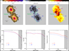 |
Fig. 1 Simulated thermal gas density, magnetic field and temperature. Top panels: central plane extracted from the cubes of the simulated thermal gas density (left), total magnetic field (central), and temperature (right) of two merging galaxy clusters. Each image covers an area of 6.42 Mpc × 6.42 Mpc. Bottom panels: spherically averaged radial profiles of the simulated thermal gas density (left), total magnetic field (central), and temperature (right) of the same system. These profiles were calculated in concentric spherical shells with a onevoxel width, 1 voxel =(10.7 kpc)3, and starting from the cluster’ centres. The shaded grey region indicates the radius above which the profiles must be taken with caution because the filament properties affect the profiles. |
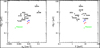 |
Fig. 2 Magnetic field vs. thermal properties. Left-hand panel: plot of the central magnetic field strength, ⟨B0⟩, vs. the central electron density, n0. Right-hand panel: plot of ⟨B0⟩ vs. the mean cluster temperature, T. For both plots, data points have been taken from Govoni et al. (2017). |
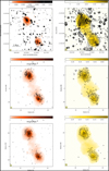 |
Fig. 3 Radio, X-ray, and Compon parameter observations vs. simulations. Top row: observations of the galaxy cluster pair A399–A401, with radio contours at about 1.4 GHz over-imposed on the X-ray images in the band 0.2–12 keV in red colors (Murgia et al. 2010) on the left, and radio contours at about 150 MHz (Govoni et al. 2019) over-imposed on the Compton parameter images in yellow colors (Hincks et al. 2022) on the right. Middle row: same as top row, but produced from the simulations presented in this work, assuming equipartition between magnetic field and relativistic electrons at each point of the computational grid. Bottom row: same as top row, but produced from the simulations presented in this work, assuming a coupling between the relativistic and thermal electrons. In the left panels, contour levels start at 120 μJy/beam and increase by factors of two, with a spatial resolution of 45″. In the right panels, contour levels start at 3 mJy/beam and increase by factors of two, with a spatial resolution of 80″. |
3 Synthetic X-ray, SZ, and radio images
In this section, we present synthetic X-ray, SZ, and radio images of the simulated system, obtained giving as the input the thermal gas density, temperature, and magnetic field cubes introduced in the previous section to the software package FARADAY (Murgia et al. 2004). The images have been produced in similar energy and frequency ranges to those available in the literature for A399–A401:
We produced the X-ray images in the 0.1–2.4 keV and 0.2–12 keV energy range, assuming a thermal bremsstrahlung model and by integrating the X-ray emissivity along the line of sight. The final output image is the X-ray brightness in the two energy ranges.
We produced the SZ effect by integrating the thermal gas density and temperature along the line of sight in order to produce the y-parameter image.
We produced synthetic radio images at the radio frequencies available in the literature (110–166 MHz, 1.375–1.425 GHz) and other frequency ranges expected with the SKA telescope, its precursor, and pathfinders, respectively, at mid- and low frequencies (i.e. LOFAR 2.0, MeerKAT+, SKA-LOW, and SKA-MID) by illuminating the magnetic field cube with a population of relativistic electrons.
In the following, we pay more attention to the generation of the radio images, since the purpose of this work is to investigate the potential of future radio instrumentation to detect diffuse synchrotron radio emission from galaxy clusters and filaments. Following Murgia et al. (2004), at each point on the computational grid we calculated the total intensity and the intrinsic linear polarisation emissivity at each frequency, by convolving the emission spectrum of a single relativistic electron with the particle energy distribution of an isotropic population of relativistic electrons: N(γ, θ) = K0γ−δ(sin θ)/2, with γmin < γ < γmax, where γ is the electron’s Lorentz factor, and θ is the pitch angle between the electron’s velocity and the local direction of the magnetic field2. In Table A.1, we indicate the parameters of the adopted distribution for the relativistic particles. We consider two scenarios: one assuming equipartition between the magnetic field (uB) and the relativistic electron (uel) energy density at every location in the ICM, and the other assuming a relativistic electron distribution with an energy density equal to 0.3% of the thermal one (uth). This factor ensures a radio power at 1.4 GHz consistent with that of radio halos in equipartition conditions and with the upper limit set from γ-ray observations (see Loi et al. 2019a and Brunetti et al. 2017). The slope of the electron energy distribution, δ, has been chosen in agreement with the spectral index α =1.6 derived by Govoni et al. (2019). The value for γmin has been chosen in order to reproduce a radio halo luminosity at 1.4 GHz and 150 MHz, in agreement with the correlation between the radio power and the cluster X-ray luminosity and the correlation between the radio power and the SZ Y-factor both in case of equipartition and in the case of relativistic electrons with an energy density equal to 0.3 percent of the thermal one, by keeping the spectral index value fixed to the value inferred by Govoni et al. (2019).
The Stokes parameters, Q and U, the polarised intensity, P = (Q2 + U2)1/2, and the polarisation plane, Ψ = 0.5 tan−1(U/Q), images were calculated by taking into account that the polarisation plane of the radio signal is subject to the Faraday rotation as it traverses the magnetised ICM. Therefore, the integration of the polarised emissivity along the line of sight was performed as a vectorial sum in which the intrinsic polarisation angle of the radiation coming from the simulation cells located at a depth, L, is rotated by an amount:
![Mathematical equation: $\[\Delta \Psi=\phi \times\left(\frac{c}{\nu}\right)^{2},\]$](/articles/aa/full_html/2024/11/aa49095-23/aa49095-23-eq1.png) (1)
(1)
where the Faraday depth, ϕ, is given by
![Mathematical equation: $\[\phi~_{\left[\mathrm{rad} / \mathrm{m}^{2}\right]}=812 \int_{0}^{L_{[\mathrm{kpc}]}} n_{\mathrm{e}~\left[\mathrm{cm}^{-3}\right]} B_{\|~[\mu \mathrm{G}]} dl.\]$](/articles/aa/full_html/2024/11/aa49095-23/aa49095-23-eq2.png) (2)
(2)
Here, B∥ is the magnetic field along the line of sight. This effect leads to the so-called internal depolarisation of the radio signal of the diffuse emission.
In Fig. 3, we compare the images of A399–A401 available in the literature (top panels) with the images obtained from the simulations, both in the case of equipartition of the relativistic electrons with the magnetic field (middle panels) and in the case of a coupling of the relativistic and thermal electrons (bottom panels) at each point of the computational grid. In the simulation of the radio emission, we considered the diffuse emission only, because the radio galaxy emission simulated is beyond the purposes of this analysis (see Loi et al. 2019a). To properly compare observations and simulations, we convolved the synthetic radio images for each Stokes parameter with the observing beam and added a Gaussian noise with rms consistent with the observations. In the left panels, total intensity radio contours at about 1.4 GHz are over-imposed on the X-ray images in the band 0.2–12 keV in red colors, while in the right panels total intensity radio contours at about 150 MHz are over-imposed on the Compton parameter images in yellow colors. While the LOFAR observations clearly show the presence of a radio ridge connecting A399 and A401, in our simulations only hints of diffuse emission between the two clusters can be identified. We stress that the simulated system is similar to A399–A401 in terms of thermal and non-thermal properties but, while the simulated system considered here is completely on the plane of the sky, A399A401 is inclined along the line of sight (Hincks et al. 2022), which implies that the radio signal actually observed from the filament between the two clusters may be larger as a result of a longer integration path along the line of sight.
In Fig. 4, we show, on the left, the radio power at 1.4 GHz versus the X-ray luminosity in the 0.1–2.4 keV energy range, and, on the right, the radio power at 150 MHz versus the Compton parameter. Black dots represent radio halos in the literature, while the red and blue colours represent the simulated radio halos, respectively, in galaxy clusters C1 and C2, with triangles when assuming equipartition between magnetic field and relativistic electrons and squares when assuming a coupling between the relativistic and the thermal electron population. We computed the X-ray luminosity, and the radio flux density at 1.4 GHz and at 150 MHz for C1 and C2 within a box 12.3 arcmin in radius (i.e., 1 Mpc). This radius comprises the region where the radio brightness is above the 3σ of the A399–A401 observations. Following van Weeren et al. (2021), we determined the P150 MHz − Y500 radio halo scaling relation using the Compton Y parameter from the Planck Sunyaev Zeldovich catalogue. For that, we converted the Y5R500 values from Planck Collaboration XXVII (2016) to Y500 using Y500 = 0.56 Y5R500 (Arnaud et al. 2010). We also converted the units from arcmin2 to Mpc2.
This analysis confirms that the amplitudes of the signals reproduced in the simulated images are consistent with the observations. Moreover, the radio power (1.4 GHz and 150 MHz), Compton parameter, and X-ray luminosity (0.1–2.4 keV) of the simulated clusters, C1 and C2, are in line with the correlations, P1.4 GHz − L0.1–2.4 keV and P150 MHz − Y500, known from the literature. The most remarkable difference is that in the case of equipartition we note a slightly prominent filamentary structure in the total intensity of the radio diffuse emission, as has also been suggested by Loi et al. (2019a).
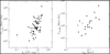 |
Fig. 4 Observed radio, X-ray, and Compton parameter correlations. Left-hand panel: radio power at 1.4 GHz versus the X-ray luminosity in the 0.1–2.4 keV energy range. The data are measurements for radio halos revealed through pointed interferometric observations at about 1.4 GHz and are the same as are shown in Loi et al. (2017), plus the new halos from Giovannini et al. (2020). Right-hand panel: radio power at 150 MHz vs. the Compton parameter. The data are the literature measurements for radio halos revealed through pointed interferometric observations at about 150 MHz reported by van Weeren et al. (2021). In both plots, the values for the galaxy clusters C1 and C2 have been shown, respectively, in red and in blue, with triangles when derived assuming equipartition between magnetic field and relativistic electrons at each point of the computational grid and with squares when assuming a coupling between the relativistic and thermal electrons. |
Sensitivities corresponding to different frequency ranges and channel widths considered in this work for the SKA, its precursors, and pathfinders. See the text for more details.
4 Results and discussion
In this section, we present our results. We have predicted the radio emission in total intensity and polarisation of a pair of galaxy clusters connected by a cosmic-web filament, similar to the system A399–A401 (Govoni et al. 2019), as is expected with the SKA-LOW, SKA-MID, LOFAR 2.0, and MeerKAT+ radio telescopes, in order to explore the potential of these instruments to study the magnetisation of the large-scale-structure of the Universe. We have produced our simulated images in different frequency ranges and with different frequency resolutions:
at low frequencies with LOFAR 2.0 and SKA-LOW:
between 110 and 166 MHz, with a spectral resolution of 12 kHz and 45 kHz;
between 110 and 350 MHz, with a spectral resolution of 45 kHz;
at intermediate frequencies with MeerKAT+ and SKA-MID:
between 900 and 1670 MHz, with a spectral resolution of 1 MHz;
between 950 and 1760 MHz, with a spectral resolution of 1 MHz.
In Table A.2, we present in a detailed way all the frequency coverages, bandwidths, and spectral and spatial resolutions considered in this work.
The SKA Magnetism Science Working Group identified as a top priority a polarisation survey with SKA-MID (Heald et al. 2020) with the following specifications: a frequency range of 950–1760 MHz, a sensitivity of 4 μJy/beam, an observing time of 15 min per pointing, and a spatial resolution of 2″. Therefore, we have adopted this observing set-up here3. At lower frequencies, discussion is still in progress to define the best observing set-up, and for this reason we consider here different configurations; that is, different frequency ranges and different spectral resolutions. Full-resolution images have been smoothed at 20″ and 80″, and for SKA-MID at 2″ as well. Noise has been added to the images, as is described in the following (see Sect. 4.1).
After convolving with the instrumental full width at half maximum (FWHM) and adding thermal and confusion noise, we performed RM synthesis with the software FARADAY (Murgia et al. 2004) on the resulting simulated Q and U cubes. To examine the output results from the RM synthesis, we exploited the information contained in the polarisation image corresponding to the peak in the Faraday depth spectrum along each line of sight in the cube, after correcting for the polarisation bias according to George et al. (2012)
![Mathematical equation: $\[P^{\prime}=\sqrt{P^{2}-2.3 \sigma_{\mathrm{Q}, \mathrm{U}}^{2}},\]$](/articles/aa/full_html/2024/11/aa49095-23/aa49095-23-eq3.png) (3)
(3)
where P and P′ are, respectively, the polarised intensity before and after the bias correction, and σQ,U is the noise over the full bandwidth in Stokes Q and U.
In the images shown in the following, we draw the contours in total intensity at 3σI and in polarisation at 5σP. In this work, we assume σQ = σU, which implies that 5σP ≈ 7σQ,U. A more severe cut in polarisation with respect to total intensity has been considered, since it translates into a false detection rate of 0.033% (see Table 1 in George et al. 2012).
4.1 Noise estimate
When considering a dataset in the form of a frequency cube with Nν channels with a thermal noise, σν, per channel and per Stokes parameter, the thermal noise, σI,Q,U, per Stokes parameter averaged over the entire bandwidth is
![Mathematical equation: $\[\sigma_{\mathrm{I}, \mathrm{Q}, \mathrm{U}}=\frac{\sigma_{\nu}}{\sqrt{N_{\nu}}},\]$](/articles/aa/full_html/2024/11/aa49095-23/aa49095-23-eq4.png) (4)
(4)
and it is assumed to be the same for each Stokes parameter.
If we apply RM synthesis, the noise over a channel of the Faraday depth cube depends on the noise in Q and U over the entire frequency band according to the following relation:
![Mathematical equation: $\[\sigma_{\mathrm{P}, \phi}=\sqrt{2 \sigma_{Q, U}^{2}}=\sqrt{\frac{2 \sigma_{\nu}^{2}}{N_{\nu}}}.\]$](/articles/aa/full_html/2024/11/aa49095-23/aa49095-23-eq5.png) (5)
(5)
For a Faraday depth cube consisting of Nϕ slices, the noise after summing over the entire width of the Faraday depth cube is
![Mathematical equation: $\[\sigma_{\mathrm{P}}=\sigma_{\mathrm{P}, \phi} \sqrt{N_{\phi}}.\]$](/articles/aa/full_html/2024/11/aa49095-23/aa49095-23-eq6.png) (6)
(6)
In Table 2, we report the expected sensitivity per single Stokes over all the frequency band (σI,Q,U), the expected sensitivity of the full Faraday depth cube after summing all the channels (σP), and the expected sensitivity in polarisation per single Faraday depth channel (σP, ϕ), for all the frequency ranges, channel widths, and integration times considered in this work and derived in the manner described above. These values were computed considering the reference values published in the LOFAR 2.0 White Paper (2023) for LOFAR 2.0, in the online documentation4 for MeerKAT+, and in Braun et al. (2019) for the SKA telescope, and include only the thermal noise. In Table 3, the confusion noise values, for the observing set-ups as in Table 2, and different spatial resolutions, are given. These values were computed according to Loi et al. (2019b)5 (but see also Condon (1974) for confusion noise estimates in total intensity only). When computing the sensitivity contours to be applied to the images, we included confusion noise, σc, by summing it in quadrature to the expected thermal sensitivity per single Stokes. For example, the sensitivity over the entire frequency band ![Mathematical equation: $\[\sigma_{I, Q, U}^{\prime}\]$](/articles/aa/full_html/2024/11/aa49095-23/aa49095-23-eq7.png) was computed according to
was computed according to
![Mathematical equation: $\[\sigma_{I, Q, U}^{\prime}=\sqrt{\sigma_{I, Q, U}^{2}+\sigma_{\mathrm{c}-I, Q U}^{2}}.\]$](/articles/aa/full_html/2024/11/aa49095-23/aa49095-23-eq8.png) (7)
(7)
Confusion noise in the Stokes parameters I (σc–I) and Q,U (σc–QU) in the frequency ranges considered in this work (Condon 1974; Loi et al. 2019b).
4.2 Results at low frequencies
In Figs. 5 and 66, we show the total intensity and polarisation images obtained at low frequencies with SKA-LOW in the frequency range of 110–166 MHz with a spectral resolution of 45 kHz at 20″ and 80″. Results for 10 and 100 observing hours, for the equipartition scenario and for a coupling between the relativistic and the thermal electrons, are shown. It should be noted that we have used the same colour-bar range for all the total intensity and all the polarisation images for easier comparison. In the case of relativistic electrons coupled with thermal electrons, the radio halo shows a smoother morphology, with less filamentary substructures and a fainter polarised emission with respect to the equipartition scenario. According to our simulations, SKA-LOW7 synthetic images at 80″ in total intensity allow us to image only the emission at the centre of the two clusters, while at 20″ marginal hints of emission along the filament connecting the two clusters can be identified as well. By increasing the observing time, we note that deeper observations do not improve the sensitivity and, consequently, do not reveal fainter structures in total intensity. Low-frequency total intensity observations are indeed limited by confusion noise after a few seconds or minutes, according to the selected spatial resolution.
Because of depolarisation, polarisation images at these frequencies allow us to detect only the brightest peaks of emission at the centre of the two clusters, at the periphery, and along the filament connecting them. Due to the lower density of polarised sources with respect to total intensity, confusion noise has a lower impact on polarimetric observations. Deeper observations are therefore precious for they reveal filamentary polarised structures associated with both the two clusters and the environment in between them, even where a total intensity counterpart has been not detected. For both spatial resolutions, a better detection of the diffuse emission is possible when considering equipartition between relativistic electrons and magnetic field.
In Appendix B, we explore the possibility of using lowfrequency SKA-LOW data at a high spectral resolution or over a larger bandwidth. The set-up with a higher spectral resolution (Fig. B.1) − 12 kHz − does not show significant differences with respect to Fig. 6, indicating that no bandwidth depolarisation is taking place or that, if it is present, its contribution is negligible. Expectations for observations over a larger frequency band − 110–350 MHz (Fig. B.2) − look only slightly better. By comparing SKA-LOW images over 110–166 MHz and over 110–350 MHz, it is evident that, at these frequencies and spatial resolution, confusion noise is also the dominant noise source in polarisation.
As a comparison, we show in Figs. 7 and 8 the total intensity and polarisation images obtained at low frequencies with LOFAR 2.0 in the frequency range of 110–166 MHz with a spectral resolution of 45 kHz at 20″ and 80″. Our simulations indicate that this instrument is capable of recovering comparable total intensity emission images to SKA-LOW, likely due to the fact that the noise is dominated by the confusion of background sources. However, in polarisation, the performance of LOFAR 2.0 is worse than that of SKA-LOW. In the equipartition scenario, only a few bright peaks of emission can be detected. These peaks are almost buried by the noise when sensitivities corresponding to 10 h of observations are considered, requiring an observing time of at least 100 h in order to be detected. By comparing LOFAR 2.0 and SKA-LOW images, the recovery of the signal after 100 h with LOFAR 2.0 is less effective than after only 10 h with SKA-LOW.
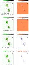 |
Fig. 5 Total intensity (left) and polarised (right) surface brightness images expected from observations in the frequency range of 110–166 MHz and with a spectral resolution of 45 kHz with the SKALOW telescope, smoothed to a resolution of 20″. Red contours represent the 3σI, and blue contours the 5σP sensitivity expected after 10 h and 100 h. The FWHM is shown in the bottom left of each image. The simulated diffuse radio emission was obtained assuming a magnetic field and a thermal gas density distribution simulated by Xu et al. (2012) and a relativistic electron population in equipartition with the magnetic field (first and third row) and with an energy density equal to 0.3% of the thermal one (second and fourth row); see the text for more details. |
4.3 Results at intermediate frequencies
In Figs. 9 and 10, we show the results obtained with SKA-MID in the frequency range of 950–1760 MHz (band 2) with a spectral resolution of 1 MHz at a spatial resolution of 20″ and 80″, respectively. We considered the sensitivity in the low part of the band (Braun et al. 2019). The detection of total intensity emission is considerably hindered by the confusion noise. Indeed, only the brightest patches at the centre of the two clusters can be revealed. At a low spatial resolution of 80″, confusion noise already dominates after 10 h, both in total intensity and in polarisation. At 20″, polarimetric data prove to be much more powerful than total intensity ones. By increasing the observing time, indeed, they also enable a good mapping of the polarised emission towards the cluster outskirts and in between the two clusters, in regions where we do not detect the total intensity counterpart, and therefore they are particularly valuable. As these images clearly show, the most important result of the paper is that the sensitivity reached in polarisation is higher than in total intensity due to a lower confusion noise. This allows us to detect the polarised emission permeating the clusters and the filament between them. Both Figs. 9 and 10 indicate that a better imaging of the polarised emission is possible in the equipartition scenario.
In order to explore the potential of the SKA-MID polarimetric survey planned by the SKA Magnetism Science Working group (Heald et al. 2020, see also text above) to study magnetic fields in galaxy clusters and beyond through diffuse synchrotron emission total intensity and polarisation observations, we produced synthetic images corresponding to an observing time of 15 min and to a spatial resolution of 2″ (see Fig. 11). With these specifications, we are able to detect total intensity patches similar to those identified at lower spatial resolution, since all these images are dominated by confusion noise. Concerning the polarised emission, we can detect only the brightest patches, and only in the equipartition scenario. When relativistic and thermal particles are coupled, indeed, the expected signal is below the noise level.
In Figs. 12 and 13, we show the expectations with MeerKAT+ observations in the frequency range of 900–1670 MHz with a spectral resolution of 1 MHz at a spatial resolution of 20″ and 80″, respectively. We note that the frequency range is similar to that considered for SKA-MID. For this reason, for comparable observing times, the results are similar to those obtained for SKA-MID, but with better performances for the last one, thanks to the higher sensitivity of this instrument (note that in Figs. 12 and 13 we use the same colour-bar ranges as in Figs. 9 and 10, respectively, for easier comparison).
Overall considerations
According to our results, the best observing instrument in order to study diffuse synchrotron emission is SKA-MID in the frequency range of 950–1760 MHz with a spectral resolution of 1 MHz. While total intensity observations are heavily limited by the confusion of background radio sources within the observing beam, polarisation observations are only marginally affected by it. In particular, total intensity observations enable only the imaging of the central regions of the galaxy clusters. In order to map the emission over all the cluster volume and along the filament connecting the two clusters, polarimetric observations are crucial. Observing times of about 100 h are necessary when spatial resolutions of 20″ are considered, while shorter observing times of about 10 h are sufficient at 80″. The combination of sensitivity and spatial resolution of intermediate-frequency polarimetric observations allow us to map the detailed morphology of the diffuse emission and possibly track its filamentary structure. Because of this, according to our results, future observations could allow us to distinguish between the equipartition scenario and the scenario based on a coupling of thermal and relativistic electrons. In the first scenario, indeed, the diffuse radio emission is expected to be more filamentary, with a less smooth morphology, and with a higher radio brightness with respect to the second scenario and consequently a better imaging of the peripheral regions of the system. This is crucial in order to characterise the magnetic field and the relativistic electrons energy spectrum and their spatial distribution in a detailed way. Although the better sensitivity of the SKA-MID makes this the favourite instrument, the performance of MeerKAT+ appears to already be good enough to conduct this kind of study, requiring observing times of about 100 h to map the diffuse emission over a significant fraction of the cluster volume.
Our predictions for SKA-MID observations also offer important hints about what we should expect from the polarisation survey planned for SKA-MID in the frequency range from 950 to 1760 MHz, with an FWHM of 2″ and an observing time of 15 min (Heald et al. 2020). According to our results, this survey will be not effective for the observation of the polarised diffuse emission associated with galaxy clusters and filaments of the cosmic web, which rather requires deeper pointed observations at lower spatial resolution.
The results presented in this work reveal that low-frequency instruments also represent a valuable tool to study diffuse synchrotron emission, not only in total intensity but also in polarisation. Even if low-frequency observations are more deeply affected by the Faraday rotation, SKA-LOW observations are expected to detect the brightest patches of polarised emission associated with the centre of galaxy clusters as well as hints of it towards their peripheries and between them, with better results for low spatial resolutions. Larger bandwidths and longer observing times perform only slightly better because at these frequencies and spatial resolutions confusion noise starts to dominate. The nominal SKA-LOW frequency range starts from 50 MHz; however, in this work we explore only the frequency range down to 110 MHz with a spectral resolution of both 45 kHz, a factor of two better than that currently used with published LOFAR polarisation works (see, e.g., Herrera-Ruiz et al. 2021) and comparable with the one adopted for the analysis of new deep LOFAR observations (Vacca et al. in prep.). A spectral resolution of 12 kHz would allow us to recover at least 90% of the polarised emission of 100 rad/m2-sources (see Fig. 10.6 in Heald et al. 2018). To exploit the entire frequency range accessible with SKA-LOW, ensuring an almost complete recovery of the polarised intensity would require a frequency resolution of at least 6 kHz. The combination of the large bandwidth and high spectral resolution of this observing set-up is computationally very expensive. Moreover, our results indicate that changing the spectral resolution from 45 kHz to 12 kHz does not significantly improve the recovery of the signal. This indicates that the inband depolarisation is negligible and that the contribution to the polarised brightness from high-RM sources is not relevant here.
Generally speaking, the polarised emission is fainter than the total intensity one, and therefore more elusive, since the intrinsic polarisation degree is ≈75–80% of the total intensity signal, for typical values of the particle spectral index. However, since the total intensity is more affected by the confusion noise than the polarised emission, our simulations indicate that deep polarimetric observations can permit us to detect a signal without a detectable total intensity counterpart. Intermediate frequencies appear to be affected by this phenomenon as well, as was also observed for the first time in a galaxy cluster system (see Vacca et al. 2022). Even if, at these frequencies, the expected emission of the sources considered in this work is fainter than at lower frequencies due to the steep spectral index, α ≳ 1, simultaneously, the Faraday rotation has a lower impact, facilitating the detection of polarised emission.
Additionally, the study of polarised emission associated with these systems can sometimes be hindered by the depolarisation of the signal within the observing beam. Our results show that polarised emission can be detected for these systems even at very low spatial resolution (80″, i.e. 110 kpc at the distance of the system), suggesting that the magnetic field is likely fluctuating over large scales in our simulations. In order to shed light on this, we computed the magnetic field power spectrum in the two clusters and along the filament, as is shown in Fig. 14. We derived for each cluster the auto-correlation length, ΛB, by applying Eq. (10) in Vacca et al. (2012),
![Mathematical equation: $\[\Lambda_{\mathrm{B}}=\frac{3 \pi}{2} \frac{\int_{0}^{\infty}\left|B_{\mathrm{k}}\right|^{2} k \mathrm{d} k}{\int_{0}^{\infty}\left|B_{\mathrm{k}}\right|^{2} k^{2} \mathrm{d} k}\]$](/articles/aa/full_html/2024/11/aa49095-23/aa49095-23-eq9.png) (8)
(8)
(see also references therein). We find ΛB = 112 kpc and ΛB = 162 kpc for clusters C1 and C2, respectively, and ΛB = 285 kpc for the filament, which is larger than the lowest spatial resolution considered in this work. These findings indicate that the beam depolarisation is not affecting our results significantly, since the magnetic field is ordered on larger scales than the beam.
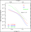 |
Fig. 14 Amplitude of the magnetic field power spectrum vs. the wave number and the scale, for the two galaxy clusters, C1 (red) and C2 (blue), and for the filament (green). As a reference, the slope of a Kolmogorov magnetic field power spectrum is shown. |
5 Conclusions
In this work, we have used cosmological MHD simulations to predict the expected surface brightness distribution of radio halos, both in total intensity and in polarisation, with nextgeneration facilities, SKA-LOW, SKA-MID, LOFAR 2.0, and MeerKAT+. Under a reasonable shape for the relativistic electron energy spectrum, we produced polarimetric synthetic radio images at low (SKA-LOW and LOFAR 2.0) and intermediate (SKA-MID and MeerKAT+) frequencies of a pair of approaching galaxy clusters similar to the system A399–A401 and with properties in agreement with systems hosting currently known radio halos, at radio, X-ray, and millimetre and sub-millimetre wavelengths. Our simulations indicate that, while total intensity emission is usually dominated by confusion noise, polarised emission is less affected by it. For this reason, polarised emission can also be detected at locations where the total intensity is buried below the noise, and therefore represents a powerful instrument to study the non-thermal components of galaxy clusters and of the cosmic web.
Our results show that in order to better reconstruct the morphology of the diffuse emission in polarisation over a significant fraction of the volume of the system and to put constraints on the spatial distribution of the non-thermal components, deep observations at resolutions of a few tens of arcseconds at intermediate frequencies appear to be the favourite option. Although the better sensitivity of SKA-MID makes this the favourite instrument, MeerKAT+ performances appear to already be good enough to conduct this kind of study, but require at least one hundred hours of observation.
Low-frequency instruments also represent a valuable tool to study the brightest patches of diffuse synchrotron emission, in total intensity and polarisation, in the centre of galaxy clusters and between them. Deep and low-spatial-resolution observations with SKA-LOW prove to be more effective, provided that the auto-correlation length of the magnetic field is larger than the observing beam. On the other hand, the capabilities of LOFAR 2.0 do not appear to be suitable for this kind of study.
Our findings are similar if we consider an equipartition scenario, as well as in the case of a relativistic electron distribution with an energy density equal to 0.3% of the thermal one. However, in the last case, the diffuse radio emission shows a smoother and less filamentary morphology, with a fainter radio brightness overall, and is therefore more elusive. Due to the combination of unprecedented resolution and sensitivity, future radio observations will allow us to characterise the properties of the diffuse synchrotron radio emission, potentially discriminating among scenarios assuming equipartition of magnetic fields and relativistic electrons and scenarios based on a coupling between thermal and non-thermal electrons. The comparison of the expectations presented here with observations that will be performed with the new generation of radio instruments will be crucial to shed light not only on the magnetic field properties but also on the distribution and energy content of the relativistic particles responsible for the diffuse synchrotron emission.
Data availability
Figures 6–13, B.1, and B.2 can be found at the following link: https://zenodo.org/records/13912170.
Acknowledgements
We thank the anonymous referee for the precious suggestions that helped to improve the quality of the paper. V.V. acknowledges support from the Prize for Young Researchers “Gianni Tofani” second edition, promoted by INAF-Osservatorio Astrofisico di Arcetri (DD no. 84/2023). FL and PM acknowledge financial support from the Italian Ministry of University and Research – Project Proposal CIR01-00010.
Appendix A Additional tables
Adopted parameters for the relativistic electron distribution.
Instrumental set-up used in the simulations: frequency coverages, bandwidths, spectral and spatial resolutions considered in this work.
Appendix B Low-frequency additional results
In this appendix, we explore the possibility to use low-frequency SKA-LOW data at higher spectral resolution or over a larger bandwidth. The set-up with higher spectral resolution (Fig. B.1), i.e. 12 kHz, does not show significant differences with respect to Fig. 6, indicating that no bandwidth depolarisation is taking place or, if present, its contribution is negligible. Observations over a larger frequency band, i.e. 110–350 MHz, are only slightly more powerful (Fig. B.2). Please, note that we use the same colour-bar ranges as in Fig. 6 for easier comparison.
References
- Akamatsu, H., Fujita, Y., Akahori, T., et al. 2017, A&A, 606, A1 [NASA ADS] [CrossRef] [EDP Sciences] [Google Scholar]
- Arnaud, M., Pratt, G. W., Piffaretti, R., et al. 2010, A&A, 517, A92 [CrossRef] [EDP Sciences] [Google Scholar]
- Bonafede, A., Giovannini, G., Feretti, L., et al. 2009a, A&A, 494, 429 [NASA ADS] [CrossRef] [EDP Sciences] [Google Scholar]
- Bonafede, A., Feretti, L., Giovannini, G., et al. 2009b, A&A, 503, 707 [NASA ADS] [CrossRef] [EDP Sciences] [Google Scholar]
- Bonafede, A., Feretti, L., Murgia, M., et al. 2010, A&A, 513, A30 [NASA ADS] [CrossRef] [EDP Sciences] [Google Scholar]
- Bonjean, V., Aghanim, N., Salomé, P., Douspis, M., & Beelen, A. 2018, A&A, 609, A49 [NASA ADS] [CrossRef] [EDP Sciences] [Google Scholar]
- Botteon, A., van Weeren, R. J., Brunetti, G., et al. 2020, MNRAS, 499, L11 [Google Scholar]
- Bourdin, H., & Mazzotta, P. 2008, A&A, 479, 307B [NASA ADS] [CrossRef] [EDP Sciences] [Google Scholar]
- Braun, R., Bonaldi, A., Bourke, T., Keane, E., & Wagg, J. 2019, arXiv [arXiv:1912.12699] [Google Scholar]
- Brunetti, G., Zimmer, S., & Zandanel, F. 2017, MNRAS, 472, 2 [Google Scholar]
- Cirimele, G., Nesci, R., & Trèvese, D. 1997, ApJ, 475, 11 [NASA ADS] [CrossRef] [Google Scholar]
- Clarke, T. E., & Enßlin, T. A. 2006, AJ, 131, 2900 [NASA ADS] [CrossRef] [Google Scholar]
- Collins, D. C., et al. 2010, AJ, 186, 308 [NASA ADS] [Google Scholar]
- Condon, J. J. 1974, AJ, 188, 279 [NASA ADS] [Google Scholar]
- Croston, J. H., Hardcastle, M. J., Birkinshaw, M., & Worrall, D. M. 2003, MNRAS, 346, 1041 [NASA ADS] [CrossRef] [Google Scholar]
- Croston, J. H., Hardcastle, M. J., Birkinshaw, M., Worrall, D. M., & Laing, R. A. 2008, MNRAS, 386, 1709 [NASA ADS] [CrossRef] [Google Scholar]
- Ebeling, H., Voges, W., Bohringer, H., et al. 1996, MNRAS, 281, 799 [NASA ADS] [CrossRef] [Google Scholar]
- Feretti, L., Giovannini, G., Govoni, F., & Murgia, M. 2012, A&ARv, 20, 54 [Google Scholar]
- Fujita, Y., Tawa, N., Hayashida, K., et al. 2008, PASJ, 60S, 343F [Google Scholar]
- George, S. J., Stil, J. M., & Keller, B. W. 2012, PASA, 29, 3 [Google Scholar]
- Giovannini, G., Cau, M., Bonafede, A., et al., 2020, A&A, 640, A108 [EDP Sciences] [Google Scholar]
- Girardi, M., Boschin, W., Gastaldello, F., et al. 2016, MNRAS, 456, 2829 [CrossRef] [Google Scholar]
- Govoni, F., Murgia, M., Feretti, L., et al. 2005, A&A, 430, L5 [NASA ADS] [CrossRef] [EDP Sciences] [Google Scholar]
- Govoni, F., Murgia, M., Feretti, L., et al. 2006, A&A, 460, 425 [NASA ADS] [CrossRef] [EDP Sciences] [Google Scholar]
- Govoni, F., Murgia, M., Xu, H., et al. 2013, A&A, 554, A102 [NASA ADS] [CrossRef] [EDP Sciences] [Google Scholar]
- Govoni F., Murgia M., Vacca V., et al. 2017, A&A, 603, A122 [NASA ADS] [CrossRef] [EDP Sciences] [Google Scholar]
- Govoni, F., Orrú, E., Bonafede, A., et al. 2019, Science, 364, 981 [NASA ADS] [CrossRef] [Google Scholar]
- Guidetti, D., Murgia, M., Govoni, F., et al. 2008, A&A, 483, 699 [NASA ADS] [CrossRef] [EDP Sciences] [Google Scholar]
- Guidetti, D., Laing, R. A., Murgia, M., et al. 2010, A&A, 514, A50 [NASA ADS] [CrossRef] [EDP Sciences] [Google Scholar]
- Heald, G., Mckean, J., Pizzo, R. F. 2018, Low frequency radio astronomy and the LOFAR Observatory: lectures from the Third LOFAR Data Processing School (Cham, Switzerland: Springer) [CrossRef] [Google Scholar]
- Heald, G., Mao, S. A., Vacca, V., et al. 2020, Galaxies, 8, 53 [NASA ADS] [CrossRef] [Google Scholar]
- Herrera-Ruiz, N., O’Sullivan, S. P., Vacca, V., et al. 2021, A&A, 648, A12 [NASA ADS] [CrossRef] [EDP Sciences] [Google Scholar]
- Hincks, A., Radiconi, F., Romero, C., et al. 2022, MNRAS, 510, 3 [Google Scholar]
- Johnstone, R. M., Allen, S. W., Fabian, A. C., & Sanders, J. S. 2002, MNRAS, 336, 299 [NASA ADS] [CrossRef] [Google Scholar]
- Komossa, S., & Böhringer, H. 1999, A&A, 344, 755 [NASA ADS] [Google Scholar]
- Laing, R., Bridle, A. H., Parma, P., & Murgia, M. 2008, MNRAS, 391, 521 [NASA ADS] [CrossRef] [Google Scholar]
- LOFAR 2.0 White Paper, v2023.1, https://www.lofar.eu/wp-content/uploads/2023/04/LOFAR2_Q_White_Paper_v2023.1.pdf [Google Scholar]
- Loi, F., Murgia, M., Govoni, F., et al. 2017, MNRAS, 472, 3605 [NASA ADS] [CrossRef] [Google Scholar]
- Loi, F., Murgia, M., Govoni, F., et al. 2019a, MNRAS, 490, 4841 [NASA ADS] [CrossRef] [Google Scholar]
- Loi, F., Murgia, M., Govoni, F., et al. 2019b, MNRAS, 485, 5285 [NASA ADS] [CrossRef] [Google Scholar]
- Loi, F., Murgia, M., Vacca, V., et al. 2020, MNRAS, 498, 2 [Google Scholar]
- Murgia, M., Govoni, F., Feretti, L., et al. 2004, A&A 424, 429 [NASA ADS] [CrossRef] [EDP Sciences] [Google Scholar]
- Murgia, M., Govoni, F., Feretti, L., & Giovannini, G. 2010, A&A, 509, A86 [NASA ADS] [CrossRef] [EDP Sciences] [Google Scholar]
- Osmond, J. P. F., & Ponman, T. J. 2004, MNRAS, 350, 1511 [NASA ADS] [CrossRef] [Google Scholar]
- Planck Collaboration XXII. 2016, A&A, 594, A22 [NASA ADS] [CrossRef] [EDP Sciences] [Google Scholar]
- Planck Collaboration XXVII. 2016, A&A, 594, A27 [NASA ADS] [CrossRef] [EDP Sciences] [Google Scholar]
- Planck Collaboration Int. VIII. 2013, A&A, 550, A134 [NASA ADS] [CrossRef] [EDP Sciences] [Google Scholar]
- Rajpurohit, K., Vazza, F., Hoeft, M., et al. 2020, A&A, 642, L13 [EDP Sciences] [Google Scholar]
- Reiprich, T. H., & Böhringer, H. 2002, ApJ, 567, 716 [Google Scholar]
- Sakelliou, I., & Ponman, T. J. 2004, MNRAS, 351, 1439 [NASA ADS] [CrossRef] [Google Scholar]
- Vacca, V., Murgia, M., Govoni, F., et al. 2010, A&A, 514, A71 [CrossRef] [EDP Sciences] [Google Scholar]
- Vacca, V., Murgia, M., Govoni, F., et al. 2012, A&A, 540, A38 [NASA ADS] [CrossRef] [EDP Sciences] [Google Scholar]
- Vacca, V., Murgia, M., Govoni, F., et al. 2018, MNRAS, 479, 776 [CrossRef] [Google Scholar]
- Vacca, V., Govoni, F., Murgia, M., et al. 2022, MNRAS, 514, 4 [Google Scholar]
- van Weeren, R., Röttgering, H. J. A., Brüggen, M., & Hoeft, M. 2010, Science, 330, 347 [NASA ADS] [CrossRef] [Google Scholar]
- van Weeren, R., Röttgering, H. J. A., Intema, H. T., et al. 2012, A&A, 546, A124 [NASA ADS] [CrossRef] [EDP Sciences] [Google Scholar]
- van Weeren, R., de Gasperin, F., Akamatsu, H., et al. 2019, SSRv, 215, 16 [Google Scholar]
- van Weeren, R., Shimwell, T. W., Botteon, A., et al. 2021, A&A, 651, A115 [NASA ADS] [CrossRef] [EDP Sciences] [Google Scholar]
- Venturi, T., et al. 2022, A&A, 660, A81 [NASA ADS] [CrossRef] [EDP Sciences] [Google Scholar]
- Vernstrom, T., Giacintucci, S., Merluzzi, P., et al. 2021, MNRAS, 505, 4178 [NASA ADS] [CrossRef] [Google Scholar]
- Vernstrom, T., West, J., Vazza, F., et al. 2023, Sci. Adv., 9, eade7233 [NASA ADS] [CrossRef] [Google Scholar]
- Wise, M. W., McNamara, B. R., Nulsen, P. E. J., Houck, J. C., & David, L. P. 2007, ApJ, 659, 1153 [NASA ADS] [CrossRef] [Google Scholar]
- Xu, H., Li, H., Collins, D., Li, S., & Norman, M. L. 2008, ApJ, 681, 2 [Google Scholar]
- Xu, H., Li, H., Collins, D. C., Li, S., & Norman, M. L. 2009, ApJ, 698, 1 [NASA ADS] [CrossRef] [Google Scholar]
- Xu, H., Li, H., Collins, D. C., et al. 2010, ApJ, 725, 2152 [NASA ADS] [CrossRef] [Google Scholar]
- Xu, H., Govoni, F., Murgia, M., et al. 2012, ApJ, 579, 40 [NASA ADS] [CrossRef] [Google Scholar]
We note that B0 refers to the magnetic field strength in the simulated cube at the voxel corresponding to the peak in thermal gas density, while ⟨B0⟩ refers to the magnetic field at the centre of the cluster as derived from the comparison of observed and synthetic rotation measure (RM) images of galaxies in the cluster.
Please note that here N(γ, θ) stands for ![Mathematical equation: $\[\frac{\mathrm{d}^{2} N}{\mathrm{d} \gamma \mathrm{d} \theta}\]$](/articles/aa/full_html/2024/11/aa49095-23/aa49095-23-eq10.png) .
.
We computed the sensitivity values in Table 2 according to Braun et al. (2019), see the following.
σc–QU is an average of σQ and σU.
Figures 6–13, B.1 and B.2 are available on Zenodo, please refer to the Data availability section in this paper.
We considered the sensitivity at 114 MHz (Braun et al. 2019).
All Tables
Sensitivities corresponding to different frequency ranges and channel widths considered in this work for the SKA, its precursors, and pathfinders. See the text for more details.
Confusion noise in the Stokes parameters I (σc–I) and Q,U (σc–QU) in the frequency ranges considered in this work (Condon 1974; Loi et al. 2019b).
Instrumental set-up used in the simulations: frequency coverages, bandwidths, spectral and spatial resolutions considered in this work.
All Figures
|
Fig. 1 Simulated thermal gas density, magnetic field and temperature. Top panels: central plane extracted from the cubes of the simulated thermal gas density (left), total magnetic field (central), and temperature (right) of two merging galaxy clusters. Each image covers an area of 6.42 Mpc × 6.42 Mpc. Bottom panels: spherically averaged radial profiles of the simulated thermal gas density (left), total magnetic field (central), and temperature (right) of the same system. These profiles were calculated in concentric spherical shells with a onevoxel width, 1 voxel =(10.7 kpc)3, and starting from the cluster’ centres. The shaded grey region indicates the radius above which the profiles must be taken with caution because the filament properties affect the profiles. |
| In the text | |
|
Fig. 2 Magnetic field vs. thermal properties. Left-hand panel: plot of the central magnetic field strength, ⟨B0⟩, vs. the central electron density, n0. Right-hand panel: plot of ⟨B0⟩ vs. the mean cluster temperature, T. For both plots, data points have been taken from Govoni et al. (2017). |
| In the text | |
|
Fig. 3 Radio, X-ray, and Compon parameter observations vs. simulations. Top row: observations of the galaxy cluster pair A399–A401, with radio contours at about 1.4 GHz over-imposed on the X-ray images in the band 0.2–12 keV in red colors (Murgia et al. 2010) on the left, and radio contours at about 150 MHz (Govoni et al. 2019) over-imposed on the Compton parameter images in yellow colors (Hincks et al. 2022) on the right. Middle row: same as top row, but produced from the simulations presented in this work, assuming equipartition between magnetic field and relativistic electrons at each point of the computational grid. Bottom row: same as top row, but produced from the simulations presented in this work, assuming a coupling between the relativistic and thermal electrons. In the left panels, contour levels start at 120 μJy/beam and increase by factors of two, with a spatial resolution of 45″. In the right panels, contour levels start at 3 mJy/beam and increase by factors of two, with a spatial resolution of 80″. |
| In the text | |
|
Fig. 4 Observed radio, X-ray, and Compton parameter correlations. Left-hand panel: radio power at 1.4 GHz versus the X-ray luminosity in the 0.1–2.4 keV energy range. The data are measurements for radio halos revealed through pointed interferometric observations at about 1.4 GHz and are the same as are shown in Loi et al. (2017), plus the new halos from Giovannini et al. (2020). Right-hand panel: radio power at 150 MHz vs. the Compton parameter. The data are the literature measurements for radio halos revealed through pointed interferometric observations at about 150 MHz reported by van Weeren et al. (2021). In both plots, the values for the galaxy clusters C1 and C2 have been shown, respectively, in red and in blue, with triangles when derived assuming equipartition between magnetic field and relativistic electrons at each point of the computational grid and with squares when assuming a coupling between the relativistic and thermal electrons. |
| In the text | |
|
Fig. 5 Total intensity (left) and polarised (right) surface brightness images expected from observations in the frequency range of 110–166 MHz and with a spectral resolution of 45 kHz with the SKALOW telescope, smoothed to a resolution of 20″. Red contours represent the 3σI, and blue contours the 5σP sensitivity expected after 10 h and 100 h. The FWHM is shown in the bottom left of each image. The simulated diffuse radio emission was obtained assuming a magnetic field and a thermal gas density distribution simulated by Xu et al. (2012) and a relativistic electron population in equipartition with the magnetic field (first and third row) and with an energy density equal to 0.3% of the thermal one (second and fourth row); see the text for more details. |
| In the text | |
|
Fig. 14 Amplitude of the magnetic field power spectrum vs. the wave number and the scale, for the two galaxy clusters, C1 (red) and C2 (blue), and for the filament (green). As a reference, the slope of a Kolmogorov magnetic field power spectrum is shown. |
| In the text | |
Current usage metrics show cumulative count of Article Views (full-text article views including HTML views, PDF and ePub downloads, according to the available data) and Abstracts Views on Vision4Press platform.
Data correspond to usage on the plateform after 2015. The current usage metrics is available 48-96 hours after online publication and is updated daily on week days.
Initial download of the metrics may take a while.