| Issue |
A&A
Volume 644, December 2020
|
|
|---|---|---|
| Article Number | A54 | |
| Number of page(s) | 38 | |
| Section | Extragalactic astronomy | |
| DOI | https://doi.org/10.1051/0004-6361/202039077 | |
| Published online | 02 December 2020 | |
AGN-driven outflows and the AGN feedback efficiency in young radio galaxies
1
Max Plank Institute for Astronomy, Königstuhl 17, 69117 Heidelberg, Germany
e-mail: santoro@mpia-hd.mpg.de
2
Department of Physics and Astronomy, University of Sheffield, Sheffield S3 7RH, UK
3
School of Physics and Astronomy, Tel-Aviv University, Tel Aviv 69978, Israel
4
ASTRON, The Netherlands Institute for Radio Astronomy, PO 2 7990 AA Dwingeloo, The Netherlands
5
Kapteyn Astronomical Institute, University of Groningen, PO 800 9700 AV Groningen, The Netherlands
6
Anton Pannekoek Institute, University of Amsterdam, Postbus 94249, 1090 GE Amsterdam, The Netherlands
7
Netherlands Research School for Astronomy, Science Park 904, 1098 XH Amsterdam, The Netherlands
Received:
31
July
2020
Accepted:
20
September
2020
Active galactic nuclei (AGN) feedback operated by the expansion of radio jets can play a crucial role in driving gaseous outflows on galaxy scales. Galaxies hosting young radio AGN, whose jets are in the first phases of expansion through the surrounding interstellar medium (ISM), are the ideal targets to probe the energetic significance of this mechanism. In this paper, we characterise the warm ionised gas outflows in a sample of nine young radio sources from the 2 Jy sample, combining X-shooter spectroscopy and Hubble Space Telescope imaging data. We find that the warm outflows have similar radial extents (∼0.06−2 kpc) as radio sources, consistent with the idea that “jet mode” AGN feedback is the dominant driver of the outflows detected in young radio galaxies. Exploiting the broad spectral coverage of the X-shooter data, we used the ratios of trans-auroral emission lines of [S II] and [O II] to estimate the electron densities, finding that most of the outflows have gas densities (log(ne cm−3) ∼ 3 − 4.8), which we speculate could be the result of compression by jet-induced shocks. Combining our estimates of the emission-line luminosities, radii, and densities, we find that the kinetic powers of the warm outflows are a relatively small fraction of the energies available from the accretion of material onto the central supermassive black hole, reflecting AGN feedback efficiencies below 1% in most cases. Overall, the warm outflows detected in our sample are strikingly similar to those found in nearby ultraluminous infrared galaxies, but more energetic and with higher feedback efficiencies on average than the general population of nearby AGN of similar bolometric luminosity; this is likely to reflect a high degree of coupling between the jets and the near-nuclear ISM in the early stages of radio source evolution.
Key words: evolution / ISM: jets and outflows / galaxies: active / galaxies: ISM / galaxies: evolution / ISM: lines and bands
© F. Santoro et al. 2020
 Open Access article, published by EDP Sciences, under the terms of the Creative Commons Attribution License (https://creativecommons.org/licenses/by/4.0), which permits unrestricted use, distribution, and reproduction in any medium, provided the original work is properly cited.
Open Access funding provided by Max Planck Society.
1. Introduction
The feedback effect of outflows driven by active galactic nuclei (AGN) is now routinely incorporated into models of galaxy evolution and has been used to explain the relative dearth of high mass galaxies (Benson et al. 2003; Bower et al. 2006), as well as the correlations between black hole mass and host galaxy properties (Silk & Rees 1998; Fabian 1999; Di Matteo et al. 2005). However, the AGN feedback effect is likely complex, involving a range of physical mechanisms on different spatial scales.
In “jet mode” feedback (sometimes labelled “maintenance mode”), relativistic jets excavate cavities in the large-scale hot (> 107 K) interstellar medium (ISM) of the host galaxies, galaxy groups, or clusters of galaxies on scales of tens of kpc; they also drive shocks into the hot gas, thus preventing the gas from cooling to form stars (Best et al. 2005; McNamara & Nulsen 2012). This feedback mode is often associated with radio-loud AGN in which the central super-massive black hole (SMBH) are accreting at a relatively low rate, thus leading to a radiatively inefficient accretion flow. However, this mode is also likely to be important in the (rarer) subset of radio-loud AGN that are accreting at higher rates and harbour radiatively efficient accretion disks.
On the other hand, in “quasar mode” feedback, the outflows driven by radiatively efficient AGN act to heat and expel the pre-existing cooler gas in the host galaxies that would otherwise form stars. The range of radial scales over which this form of feedback operates is currently controversial, with estimates ranging from tens of pc to > 10 kpc (Greene et al. 2012; Harrison et al. 2012, 2014; Liu et al. 2013; Husemann et al. 2016; Villar-Martín et al. 2016; Tadhunter et al. 2018; Revalski et al. 2018; Fischer et al. 2018; Baron & Netzer 2019a). Although this feedback mode is often linked to winds driven by the radiation pressure of the central AGN (King & Pounds 2015), relativistic jets may play a significant role, even in cases in which the radio luminosity is relatively modest (L1.4 GHz < 1024 W Hz−1). Indeed, there is growing evidence that radio jets can have a broader impact than considered so far and may provide the dominant outflow driving mechanism for AGN over a wide range of radio powers.
This is based both on statistical studies of large samples of Sloan Digital Sky Survey (SDSS)-selected AGN (e.g. Mullaney et al. 2013; Comerford et al. 2020) and on a growing number of observations of individual objects in which the outflows show detailed morphological associations with the radio lobes on kpc scales (e.g. IC 5063: Morganti et al. 2007, 2015; Tadhunter et al. 2014; SDSS J165315.06+232943.0: Villar-Martín et al. 2017; NGC 613: Audibert et al. 2019; 3C 273: Husemann et al. 2019a; HE 1353−1917: Husemann et al. 2019b; ESO 428−G14: May et al. 2018; NGC 5929: Riffel et al. 2014; NGC 1386: Rodríguez-Ardila et al. 2017; and the targets in the sample of Jarvis et al. 2019).
Recent numerical simulations have also demonstrated that, despite their highly collimated nature, the relativistic jets of radio-loud AGN can inflate extensive bubbles of outflowing gas as they fight their way through the dense and inhomogeneous ISM in the central regions of galaxies (Wagner et al. 2013; Mukherjee et al. 2016, 2018). This process is particularly important in the first phase of expansion, when the jets are just born or still young (i.e. < 106 yr). In this way, the outflows driven by the jets on kpc scales can be as broad and extensive as those driven by the radiation pressure of the central AGN. However, we do not yet fully understand how this feedback mechanism – jets acting on the cooler phases of the ISM – works in detail; there also remain considerable uncertainties about the masses and kinetic powers of the resulting jet-induced outflows and the extent to which they can truly affect the evolution of the host galaxies.
Representing a high-radio-power population of AGN in which the nascent radio jets are starting to expand through the central regions of the host galaxies, gigaherz peaked sources (GPS: with diameters D < 1 kpc) and compact steep spectrum (CSS: D < 15 kpc) sources (O’Dea 1998) are key objects for testing models of jet-induced feedback on kpc scales. There is now clear evidence from both spectral ageing and source expansion studies that CSS and GPS sources are genuinely young rather than merely “frustrated” by their interaction with the dense circum-nuclear gas (Owsianik et al. 1998; Murgia et al. 1999; Tschager et al. 2000; Giroletti & Polatidis 2009; An & Baan 2012).
Optical imaging and spectroscopy observations of CSS and GPS sources have demonstrated that their emission-line regions tend to be aligned with, and on similar scales to, the radio structures (de Vries et al. 1997; Axon et al. 2000; Labiano 2008; Batcheldor et al. 2007; Santoro et al. 2018) – reminiscent of the “alignment effect” observed on larger spatial scales in high-z radio galaxies (McCarthy et al. 1987; Best et al. 1996). Their optical spectra often show strong emission lines disturbed kinematics that are usually more extreme, in terms of line widths and velocity shifts, than those associated with samples of extended radio sources with similar redshifts and radio powers (Gelderman & Whittle 1994; Holt et al. 2008, 2009; Shih et al. 2013; Molyneux et al. 2019). However, although these observations support the idea that the jets in CSS and GPS sources are interacting strongly with the cooler phases of the ISM in the host galaxies, the masses and energetic significance of the resulting outflows have yet to be accurately quantified in most objects. This is because it has proved challenging to quantify key properties of the outflow regions such as their densities, spatial extents and degree of dust extinction (e.g. see Harrison et al. 2018).
In particular, estimates of electron density are key to precisely quantifying the warm outflows. In the optical band, it is common practice to measure electron densities using the [O II] 3729/3726 or [S II] 6717/6731 line ratios (we will refer to these line ratios as the “classical [O II] and [S II]” line ratios). However, due to the relatively low critical densities of the transitions involved, these ratios become insensitive at density above ne ∼ 103.5 cm−3. Thus, alternative methods are required to determine whether the warm outflows contain high density components. The first studies which go in this direction – for example, using trans-auroral [S II] and [O II] ratios – are finding electron densities that are up to two orders of magnitude higher than typically estimated or assumed in studies of warm outflows, demonstrating that components of the outflowing gas have higher densities than the global ISM of the AGN host galaxies (Holt et al. 2011; Rose et al. 2018; Santoro et al. 2018; Spence et al. 2018; Baron & Netzer 2019b; Davies et al. 2020). This has important implications for estimates of key outflow parameters such as the mass outflow rates, kinetic powers, and AGN feedback efficiencies.
Here we use deep X-shooter/VLT observations, supplemented by Hubble Space Telescope (HST) imaging observations, to study AGN feedback and its efficiency in driving warm ionised gas outflows in a sample of nine compact radio sources selected from the southern 2 Jy sample (Tadhunter et al. 1998; Dicken et al. 2009). In particular, we take advantage of the broad wavelength coverage of the X-shooter observations to probe the presence of high density outflowing gas via a technique, pioneered by Holt et al. (2011) and Santoro et al. (2018) for compact radio sources, which uses the [O II](3726+3729)/(7319+7330) and the [S II](4069+4076)/(6717+6731) line ratios (we will refer to these as the “trans-auroral [O II] and [S II] line ratios” or, in short, “tr[O II]” and “tr[S II]”) and investigate how this affects the derived outflow and AGN feedback properties.
In Sect. 2 we describe the sample selection, the observations and the data reduction strategy. In Sect. 3 we discuss the modelling of the nuclear spectra of our targets, including stellar continuum and gas emission lines. In Sect. 4 we describe the criteria adopted to identify gas outflows and determine their kinematical properties (Sect. 4.1), spatial extents (Sect. 4.2), gas densities and levels of dust extinction (Sect. 4.4). In Sect. 5 we calculate the mass outflow rates, the outflow kinetic powers and the AGN feedback efficiencies for our compact radio sources and compare them with those of other AGN samples available in the literature in Sect. 6. Finally, in Sect. 7 we discuss our findings, focusing on how more accurate estimates of the outflow densities affect the way we quantify the AGN feedback efficiency, and on the relative importance of jet-induced feedback in the near-nuclear regions of AGN host galaxies.
Throughout this paper we adopt a flat ΛCDM cosmology with H0 = 70 km s−1 Mpc−1, Ω0 = 0.28 and Ωλ = 0.72.
2. Observations and data reduction
2.1. The sample
Our sample selection has been performed starting from the southern 2 Jy sample, with steep radio spectra and redshifts in the range 0.05 < z < 0.7, as described in Tadhunter et al. (1998) and Dicken et al. (2009). The southern 2 Jy sample is a complete sample of radio galaxies that have been extensively studied across the electromagnetic spectrum thanks to observations in the optical (Tadhunter et al. 1993, 1998), the IR (Dicken et al. 2008; Inskip et al. 2010), the radio (Morganti et al. 1993, 1997, 1999; Venturi et al. 2000) and the X-ray (Mingo et al. 2014) bands.
We selected sources that are in the crucial phase of a nascent radio jet starting to expand through the near-nuclear ISM. According to this criterion, the objects chosen for the current study (see Table 1) comprise a complete sub-sample of all 7 CSS and GPS sources (D < 15 kpc) in the southern 2 Jy sample, with the addition of PKS 2314+03 (3C 459) and PKS 1549–79. We added PKS 2314+03 because, despite being an extended (D ∼ 29 kpc) FRII radio source, its compact radio core has a steep spectrum and shows similarities with CSS and GPS sources (see Thomasson et al. 2003). On the other hand, PKS 1549–79 was included since, although it is a highly asymmetric radio source with a bright, flat-spectrum core, there is evidence that its radio structures are intrinsically compact, rather than just appearing compact as a result of its jets pointing close to our line of sight (see discussion in Holt et al. 2006; Oosterloo et al. 2019). In Table 1 we list the final targets that are part of our sample and their main radio properties.
Main properties of the radio sources in our sample, namely their radio ID (Col. 1), infrared ID (Col. 2), radio classification (Col. 3), redshift (Col. 4), angular-to-linear conversion factor (Col. 5), luminosity at 5 GHz (Col. 6), position angle (Col. 7), and linear diameter (Col. 8).
All of the sources in our sample have high resolution VLBI radio observations (Tzioumis et al. 2002; Thomasson et al. 2003; Oosterloo et al. 2019), and previous optical, mm and radio observations have provided evidence for AGN-driven outflows in multiple gas phases in many of the objects (see e.g. the work by Holt et al. 2006, 2008, 2009; Morganti et al. 2005; Santoro et al. 2018; Oosterloo et al. 2019). Santoro et al. (2018) carried out a detailed study of the warm ionised gas for PKS 1934–63 which serves as a pilot for the current paper. For this reason this source has also been included in our sample, and we redirect the reader to the Santoro et al. (2018) paper for the details on the data analysis process.
2.2. Observations
2.2.1. X-shooter observations
We carried out an observational campaign for the full sample using X-shooter at the VLT/UT2 in SLIT mode. The observing programme and the period of execution are reported in Table 2, together with the exposure times for the visual (VIS), the ultraviolet-blue (UVB) and the near-IR (NIR) arm. Sky subtraction was facilitated by nodding the source within the slit for most galaxies of the sample. However, for PKS 1151–34 and PKS 1814–63 the slit was nodded to a separate sky aperture due to the presence of a nearby companion galaxy along the slit and extended starlight on the scale of the slit, respectively. The instrument SLIT mode was used with a 1.6 × 11 arcsec slit for the UVB arm, a 1.5 × 11 arcsec slit for the VIS arm, and a 1.5 × 11 arcsec slit for the NIR arm. The resulting long-slit spectra have pixel sizes of 0.16, 0.16, and 0.20 arcsec in the spatial direction for the UVB, VIS, and NIR arms, respectively. In Table 2 we also report the slit position angle and the estimated seeing of the observations for each galaxy. We note that in most cases the slit was not aligned with the radio axis (see Tables 1 and 2).
Details of the X-shooter observations.
The seeing full-width at half maximum (FWHM) was estimated by using acquisition images of our targets taken during the observing time. For each galaxy, we selected a few stars in the acquisition images, extracted their spatial profiles (using a mock slit with the same width used for the actual observations) and fit them with Gaussian functions. The seeing, as reported in Table 2 is the average FWHM of the best-fit Gaussian functions; uncertainties have been derived as the standard error of the DIMM seeing values recorded during the observations period by the observatory. For PKS 1549–79 we were not able to retrieve any acquisition image and thus lack an estimate of the seeing FWHM. Therefore, as a reference a we report that the average DIMM seeing recorded during the observations, but this is likely to underestimate the true seeing for this object, which was observed at a high air mass.
Data reduction of the X-shooter data was performed using ESO REFLEX and following the same approach used in Santoro et al. (2018). This includes a standard data reduction (e.g. bias subtraction, flat fielding and flux calibration). In addition, second-order calibrations were applied to remove hot and bad pixels and improve the sky subtraction. We derived the average uncertainty in the wavelength calibration and the average instrumental spectral resolution by fitting sky emission lines and measuring their line centres and FWHM, respectively. We find that the wavelength calibration uncertainty is 20 km s−1, 5 km s−1 and 3 km s−1, while the instrumental spectral resolution is 90 km s−1, 60 km s−1 and 90 km s−1 for the UVB, VIS, and NIR arms, respectively. The relative flux calibration accuracy was estimated to be between 5 and 10% taking into account flux variations due to calibration with different standard stars. We extracted the nuclear X-shooter spectra of our galaxies by setting an aperture with diameter equal to three times the estimated seeing as reported in Table 2.
2.2.2. HST observations
In order to determine the extents of their warm outflows, three of the sources in our sample – PKS 0023–26, PKS 1306–09, and PKS 1549–79 – were observed using the High Resolution Camera (HRC) or Wide Field Camera (WFC) of the Advanced Camera for Surveys (ACS) mounted on the HST. The reduction and analysis of the ACS/HRC [O III] imaging observations for PKS 1549–79 is presented in Batcheldor et al. (2007), and further analysis and discussion on the relationship between the [O III] and radio structures in this source is presented in Oosterloo et al. (2019). Here we present new ACS/WFC observations for PKS 0023–26 and PKS 1306–09, which were taken under HST programme GO12579 (PI J. Holt).
The new HST observations are detailed in Table 3. They were taken using the ramp filters in ACS/WFC, with narrow-band filters (Δλ ∼ 140 Å) centred on the wavelengths of the redshifted [O III]λ5007 Å features, and medium-band filters (Δλ ∼ 580 Å) centred on adjacent continuum regions, in order to facilitate continuum subtraction. Observations in each filter comprised four separate exposures taken in a box dither pattern. The data were reduced using the standard CALACS pipeline (Pavlovski et al. 2005) including de-striping and charge transfer effect (CTE) corrections. Following image registration, the continuum images were subtracted from the emission-line images to create line-free [O III] emission line images; these are compared with the stellar continuum images in Fig. 1.
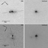 |
Fig. 1. HST ACS/WFC images of PKS 0023–26 (top) and PKS 1306–09 (bottom). Left-hand panels: narrow-band [O III] images, right-hand panels: intermediate-band continuum images. In each case, the dashed line shows the direction of the radio axis. We note that in both cases, the brightest extended [O III] structures are closely aligned in angle with the radio axes (within ∼10°). |
Details of the HST ACS/WFC observations of PKS 0023–26 and PKS 1306–09.
3. Data analysis
3.1. Stellar continuum modelling and redshift determination
To properly investigate the physical and kinematic properties of the warm ionised gas in the galaxies of our sample, it is crucial to subtract the contribution of the starlight from their nuclear spectra and determine an accurate systemic velocity. To perform this task, the nuclear spectra of the galaxies were fitted using pPXF (Cappellari & Emsellem 2004; Cappellari 2017) in combination with a set of stellar models from Bruzual & Charlot (2003) with solar metallicity and ages of 0.005, 0.025, 0.1, 0.29, 0.64, 1.4, 2.5, 5, 11 and 12.3 Gyr. All the emission lines associated with the warm ionised gas were masked out during the fitting procedure. The nuclear spectrum of each galaxy was first de-reddened taking into account Galactic extinction and then fitted using the redshift reported in Table 1 as a first guess for the systemic velocity. The E(B − V) values for the Galactic extinction towards the direction of each galaxy were taken from the NASA/IPAC infrared science archive1 and the reddening correction was performed using the Cardelli et al. (1989) reddening law. In Table 4 we report the E(B − V) values adopted to correct for Galactic extinction, and the redshifts derived from the starlight fitting procedure described above.
Radio sources in the sample and their galactic E(B − V) values (Col. 2) taken from the NASA/IPAC infrared science archive, and stellar absorption-line redshifts (Col. 3) derived from our stellar continuum fit.
By using this procedure, we were able to recover and subtract the stellar continuum in the nuclear spectra of seven out of the nine sources of our sample. However, two sources – PKS 1814–63 and PKS 1151–34 – required a separate treatment. In the case of PKS 1814–63, the light from a bright, nearby star close (in projection) to the galaxy nucleus contaminates the nuclear spectrum. After considering different stellar spectra taken from the online X-shooter spectral library2, we obtained an optimal fit of the nuclear spectrum continuum features by running pPXF and using a combination the stellar template spectrum of a G5 star at zero redshift (i.e. HD 8724), and a single stellar model from Bruzual & Charlot (2003) with age 11 Gyr and solar metallicity at the redshift of the galaxy. On the other hand, the presence of prominent emission lines from the Broad Line Region (BLR) and continuum from accretion disk of the AGN in the nuclear spectrum of PKS 1151–34 (classified as a type 1.5 Seyfert galaxy by Véron-Cetty & Véron 2006) prevents us from performing a careful subtraction of the starlight across the full spectrum. However, we were still able to estimate the redshift of this source by limiting the starlight fitting to the wavelength range between about 3400 and 4000 Å where the stellar features of the Ca H and K absorption doublet are prominent and there is less contamination due to AGN light. The best models for the starlight continuum of our targets are shown in Appendix A together with the continuum-subtracted spectra that have been used to perform the analysis described in the following sections.
3.2. Emission line modelling
After subtracting the starlight features from the nuclear spectra of our targets we obtained pure emission-line spectra. In Fig. 2 we show the profiles of some of the main emission lines observed in PKS 0023–26, while analogue plots are shown for the other objects in Appendix A. As expected, all targets show complex line profiles with broad wings, confirming the complex kinematics of the gas and the presence of outflows. In order to derive the parameters needed for our analysis, we performed the modelling of the emission lines by using Gaussian functions and custom-made IDL routines based on the MPFIT (Markwardt 2009) fitting routine.
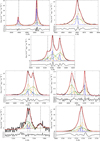 |
Fig. 2. Emission-line profiles for PKS 0023–26: First row: [O III]λλ4958,5007 Å (left panel) and Hβ line (right panel) fits. Second row: Hα + [N II]λλ6548,84 Å line fits. Third row: [S II]λλ6717,31 Å (left panel) and [S II]λλ4069,76 Å (right panel) trans-auroral line fits. The latter fit includes also the Hδ line. Fourth row: [O II]λλ7319,30 Å (left panel) and [O II]λλ3726,29 Å (right panel) trans-auroral line fits. The former fit also includes the [O II]λ7381 Å line which has been modelled with a single Gaussian component. In each of the sub-figures the upper panel shows the best fit (red solid line) of the observed spectrum (black solid line) while the lower panel shows the residuals of the fit. The different kinematic components used for the fit of each emission line are showed with different colours and line styles. In the case of doublets where flux ratios have been fixed (i.e. the [O III]λλ4958,5007 Å and the [N II]λλ6548,84 Å) we show the total profile of each doublet kinematic component. The vertical dashed lines marks the rest-frame wavelength of the fitted emission lines. Wavelengths are plotted in Å, and the flux scale is given in units of 10−17 erg s−1 cm−2 Å−1. |
For our purposes, we need to recover the fluxes of a significant number of emission lines, many of which are blended with other emission lines and/or have low signal to noise (S/N) ratios. We thus built a reference model by fitting high S/N emission lines that are less affected by blending. This reference model gives us an indication of the number of kinematic components needed to model the warm ionised gas emission lines, and of the velocity centroid and FWHM of each of these components. We fit the emission lines that are needed for our study by performing seven separate fits, more specifically we fit the [O II]λλ3726,29 Å, the [S II]λλ4069,76 Å plus the Hδ, the Hβ, the [O III]λλ4958,5007 Å, the [N II]λλ6548,84 Å plus the Hα, the [S II]λλ6717,31 Å and the [O II]λλ7319,30 Å (plus the [O II]λ7381 Å line, modelled with a single Gausssian function when needed) lines. Constraints on the line separation, width and relative intensities within each group of emission lines have been set according to atomic physics following the approach described in Santoro et al. (2018).
To build our reference model we fit the [O III]λλ4958,5007 Å doublet, whose emission lines are only mildly affected by blending and have very high S/N in the nuclear spectra of our targets, with up to four kinematic components. Each kinematic component consists of two bounded Gaussian functions with the same width, fixed separation (47.9 Å) and fixed relative fluxes ([O III]λ5007 Å = 2.98 × [O III]λ4958 Å) according to atomic physics. Based on χ2 statistics and residual minimisation we selected as the best fit model the one that minimised the number of kinematic components needed to fit the observed line profiles, and refer to this as the [O III] reference model. It should be noted that for PKS 1549–79 and PKS 2314+03 we fit the [O III]λλ4958,5007 Å and the Hβ lines together, due to the difficulties of fitting the Hβ line alone using the model derived from the [O III] line, and used this as our reference model for the remaining lines.
The [O III] reference model was then used to provide constraints on the fit to the remaining emission lines in the nuclear spectra. It is worth mentioning that the successful fitting of an emission line obtained by using a reference model does not always imply that all the kinematic components of this model are actually detected. This reflects the fact that, while high S/N emission lines such as [O III] can give us a reliable model for the gas kinematics, the relative fluxes of the different kinematic components of an emission line depend on the physical properties and ionisation source of the gas. More generally, when it was not possible to fit an emission line doublet with a reference model because of low S/N (i.e. the [O II]λλ7319,30 Å and/or [S II]λλ4069,76 Å emission lines in PKS 0252–71, PKS 1306–09, PKS 1814–63 and PKS 2314+03) we recover the total lines flux by using a simple model with a single kinematic component per emission line.
For two of our galaxies, namely PKS 1549–79 and PKS 1151–34, we needed to adjust the emission line fitting strategy. In the case of PKS 1549–79 the [O III] reference model did not allow us to recover properly the flux of some of the emission lines (see also the work by Tadhunter et al. 2001; Holt et al. 2006). Mismatching kinematics between different emission lines in the nuclear spectrum of a target is expected due to the fact that different emission lines trace gas with different levels of ionisation and/or physical conditions. In this case, we obtained an alternative reference model (that we refer to as the [O II] reference model) by fitting the [O II]λλ3726,29 Å doublet with the same procedure described above for the [O III] reference model. This is motivated by the fact that one of our main goals is to study the trans-auroral lines and, among these, the [O II]λλ3726,29 Å lines usually have higher S/N and are less subject to blending with emission lines from other elements. The [O II] reference model was used to fit the [N II]λλ6548,84 Å + Hα, the [O II]λλ3726,29 Å and the [S II]λλ6717,31 Å, while all the other lines have been fitted using the [O III] reference model.
In the case of PKS 1151–34, modelling the emission lines is challenging due to the presence of direct BLR and continuum emission from the AGN, and also subject to higher uncertainties due to our inability in subtracting the contribution of the starlight continuum from its nuclear spectrum. The strategy we adopted to build a reference model for the emission line fit has been aimed at getting some constrains to properly model the Hβ BLR emission from the brighter Hα BLR emission, as described in Appendix A.
In Fig. 2 we show the results of the modelling for the warm ionised gas emission lines of PKS 0023–26, while analogue plots are shown for the remaining galaxies of our sample in Appendix A. In Table 5 we report the kinematic properties (i.e. centroid velocity and FWHM of the different kinematic components) of the reference models for all the galaxies in our sample. Errors have been estimated taking into account both the instrumental and the model (fit) uncertainties, and the FWHM have been corrected for instrumental broadening.
Velocity shifts (v) and FWHM (in km s−1) of the [O III] reference model kinematic components (indicated with a progressive number from 1 to 4 from lower to higher FWHM).
4. Basic results
One of the main aims of our study is to derive the mass outflow rates Ṁ, kinetic powers Ė, and AGN feedback efficiencies F for the warm outflows of the targets in our sample (Sect. 5). These quantities mainly rely on the estimates of the more basic outflows properties such as their kinematics, electron densities, dust extinction and spatial extent, which are described in the current section. Here we stress the importance of deriving gas electron densities from diagnostics that are able to probe the high gas density regime (Sect. 4.4), and rely on estimates of the gas ionisation parameter (Sect. 4.3), and photoionisation models (described in detail in Appendix B).
4.1. Gas kinematics
The results of the emission line modelling presented in Sect. 3 clearly show that all our targets have complex line profiles with broad wings that require multiple kinematic components to be properly modelled. We label as “Broad” any kinematic components in the [O III] reference model with FWHM > 500 km s−1 and/or velocity shift v < −500 km s−1 and associate these components with the outflowing gas. Confirming previous results (see Holt et al. 2008, and references therein), we find all our targets have at least one broad component and thus show signs of hosting an outflow. Remarkably, some of the kinematic components of our reference models show broadening up to FWHM ∼ 2000 km s−1 and blueshifts up to about −1000 km s−1. According to our criterion, for PKS 1549–79, PKS 2135–209 and PKS 2314+03 all the [O III] kinematic components can be considered as being associated with outflowing gas. This is a clear sign that the outflowing gas comprises a large fraction of the total warm ISM sampled by the spectroscopic slit. Therefore, for these sources we use the total emission of the components detected in [O III] when determining the outflow properties.
In Table 6 we summarise the kinematic properties of the outflowing gas for each galaxy in our sample. To quantify the velocity and the FWHM of the outflowing gas, we calculated the flux weighted average velocity (i.e. v) and FWHM of the [O III] reference model broad components. In addition, we derived an estimate of the maximum velocity (i.e. vmax) that the outflowing gas can reach by calculating the velocity at which the cumulative flux of the [O III] reference model broad components (integrated from low to high velocities in the velocity space) equals 5%, following the approach of Rose et al. (2018). Due to the overall redshifted [O III] line profile for PKS 1151–34, the vmax has been estimated as the velocity at which the cumulative flux of the [O III] reference model broad components is 95%. The errors on the vmax have been calculated using the errors on the broad components velocity from the fitting procedure.
Kinematic parameters for the outflows: flux weighted velocity (Col. 2) and FWHM (Col. 3), and maximum outflow velocity (Col. 4).
4.2. The spatial extents of the outflows
The radial extent of the outflowing gas is one of the key parameters for estimating the outflow properties, but also one of the hardest to measure (see Harrison et al. 2018, and references therein). Here we adopt the approach of first attempting to estimate the outflow radii using optical HST imaging and X-shooter spectroscopy observations.
Potentially, the most direct estimates of the outflow radii are provided by our HST [O III] images, which are available for PKS 0023–26, PKS 1306–09 and PKS 1549–79 (see Sect. 2.2.2, Fig. 1, Batcheldor et al. 2007; Oosterloo et al. 2019). The main assumption here is that the [O III] emission detected in the HST images is dominated by the outflows. It should be noted that while this assumption fully holds for PKS 1549–79, whose [O III] emission line profile is completely dominated by the outflow (see Sect. 3.2, also Oosterloo et al. 2019), it might lead us to overestimate the outflow spatial extents in the other two galaxies if there is a contribution from kinematically-quiescent emission-line gas that lies at larger radial distances from the nuclei than the radio sources However, in both PKS 0023–26 and PKS 1306–09 the brightest off-nuclear emission regions are situated along the direction of the radio jets. This agrees with results for other CSS and GPS sources (e.g. de Vries et al. 1997; Axon et al. 2000) and, more generally, for many radio galaxies which show kinematically disturbed [O III]-emitting gas at the location of the radio jets (e.g. Clark et al. 1998; Villar-Martín et al. 1999, 2017; Morganti et al. 1997). We thus consider our initial assumption to be reasonable for our type of source.
In each of the three objects with HST imaging, we estimate the outflow radius as the distance between the continuum nucleus of the galaxy and the position of the maximum in the flux of the off-nuclear emission in the continuum-subtracted [O III] images. These HST estimates for the warm outflow radii are within a factor of 2 of the radio source radii (see Table 7). However, it is perhaps surprising that the brightest off nuclear emission-line region in PKS 1306–09 is apparently situated well beyond the radio source, despite its close alignment with the radio source axis suggesting a jet-cloud interaction. One possible explanation for this is that, rather than the two bright radio components detected in the VLBI observations of PKS 1306–09 being symmetrically placed on either side of the nucleus, as we assumed, one such “lobe” is centred on the nucleus (i.e. the source is highly asymmetric). In that case, the radio source extent (2.2 kpc) would be similar to the [O III] extent (1.9 kpc). We note that Tzioumis et al. (2002) find that only 30% of the total radio emission at 2.29 GHz in PKS 1306–09 is recovered in their VLBI observations. This leaves open the possibility that there is substantial diffuse radio emission that is resolved out at VLBI resolution; some of this diffuse emission may be situated further to the NW than the “lobe” detected in their image.
Radii of the warm ionised gas outflows as estimated from the optical data (HST or X-shooter) (Col. 2) and the radio source radii taken from the literature (Col. 3).
An alternative to direct imaging for measuring the outflows extent is to use the spectro-astrometry technique (see Santoro et al. 2018). This has the advantage that it can be used to isolate the broad wings associated with the outflowing gas, and measure their spatial extents in the direction of the spectroscopic slit. However, since it is likely that the warm outflows in CSS and GPS sources are closely aligned with the radio axes (see above), this can only be reliably done for objects in which the X-shooter slit PA is reasonably well aligned with the radio axis (i.e. within 20°, see Sect. 2.2). Three objects in our sample fulfil this criterion: PKS 0252–71, PKS 1934–63 and PKS 2135-20.
Spectro-astrometry measurements for PKS 1934–63 have already been presented in Santoro et al. (2018). Following the approach described in that paper, we built the position-velocity diagrams shown in Fig. 3 for PKS 0252–71 and PKS 2125-20 by using the region of the slit spectrum around the high S/N [O III]λ5007 Å emission line. In each case, we extracted spatial slices from the long-slit spectra at different rest-frame velocities across the [O III]λ5007 Å profile, subtracted an appropriately scaled continuum slice, then fitted the resulting [O III] spatial profiles with Gaussians in order to determine the spatial centroids. To increase the S/N of the spatial profiles, especially in the case of PKS 0252–71, for every velocity we extracted the spatial slice over 5 pixels (corresponding to 2.5 Å or ∼90 km s−1 in the wavelength direction). The continuum slices were extracted on the blue and red sides of the [O III]λλ4958,5007 Å doublet over the wavelength intervals indicated in Table 8. The position-velocity diagrams in Fig. 3 show the offsets of the fitted centroids of [O III] spatial profiles relative to the galaxy continuum centroid as a function of the rest-frame velocity, where the latter was determined using the redshift derived from the stellar population fitting (see Table 4).
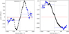 |
Fig. 3. Position-velocity diagrams obtained by applying the spectro-astrometry technique to the [O III]λ5007 Å line in the slit spectra of PKS 0252–71 and PKS 2135–209. The diagrams show the position of the fitted centroids of the [O III]λ5007 Å emission line spatial profiles, expressed as offsets in parsecs from the host galaxy centre, as a function of velocity measured with respect to the [O III]λ5007 Å rest-frame velocity. The black dotted vertical and horizontal lines mark the zero point of the two axes. The blue dashed lines mark the error weighted mean position of the [O III] spatial profiles offsets at v < 500 km s−1 and at v > 500 km s−1 (shown in blue), while the red dashed line marks their average. |
Spectral windows used to extract spatial profiles of the stellar continuum light (Cols. 2 and 3) and of the outflowing gas (Col. 4) from the X-shooter slit spectra.
As can be seen in Fig. 3, both galaxies show an S-shaped profile that appears symmetric with respect to the systemic velocity, similar to what has been found for PKS 1934–63 (Santoro et al. 2018). There is a clear velocity gradient around the systemic velocity that likely reflects the gas rotation within the galaxies due to gravitational motions, or alternatively a low velocity bipolar outflow. However, at larger velocities, where we clearly probe the outflowing gas, the profile flattens out. For PKS 2135–209 the overall curve is spatially shifted with respect to the zero point along the y axis (i.e. the putative centre of the galaxy). This is likely to be due to dust obscuration, which can potentially shift the position of the galaxy spatial profile peak relative to the position of the AGN. We use the error-weighted mean positions of the gas at v < 500 km s−1 and at v > 500 km s−1 (blue dashed lines in Fig. 3) as an indicators of the approaching and receding positions of the outflowing gas. In both objects we observe a significant offset between these two values, supporting the idea of a bi-polar geometry for the outflows. Under the assumption of a bi-polar outflow we use the latter error-weighted mean positions to estimate the true AGN nucleus position (red dashed line in Fig. 3) as their average value, and the radial extent of the outflow as half of their separation.
The outflow radii that we find using the spectro-astrometry method are reported in Table 7. While for PKS 2135–209 the outflow radius agrees well with the radio source radius, similar to the results found for PKS 1934–63 in Santoro et al. (2018), in the case of PKS 0252–71 the estimated outflow radius is approximately half the radial extent of the radio source. The latter result can be explained if the outflow maintains a roughly constant surface brightness as a function of radius out to the full extent of the radio source, rather than being concentrated at the edges of the radio lobes.
Finally, for the remaining three galaxies – PKS 1151–34 and PKS 1814–63, PKS 2314+03 – we followed the method of Rose et al. (2018) and Spence et al. (2018) and compared the measured FWHM of the spatial profiles of the broad wings of [O III] or Hβ emission lines with the seeing FWHM from Table 2 (see Sect. 2.2.1), in order to determine whether these profiles are spatially resolved. In this case, the emission-line and continuum slices were extracted from the long-slit spectra over the rest-frame velocity/wavelength ranges given in Table 8. The continuum slices were scaled to take into account the different window widths, and then subtracted from the broad-wing spatial profiles of the emission lines before fitting them with Gaussians. We found for all three objects the outflows are spatially unresolved in the direction of the X-shooter slit, in the sense that the [O III] FWHM are within 3σ of the seeing FWHM. Therefore, we followed Rose et al. (2018) and determined upper limits on the outflow radii using the following formula:
Reassuringly, the resulting upper limiting radii are all larger than the estimated radio source radial extents. Therefore, for these three objects we take the radio source radial extents as the best available estimates of the warm outflow radii. This is justified on the basis of results obtained above and in previous studies on the similarities between the scales and position angles of the radio sources and extended [O III] emission-line regions.
To summarise, in cases where we can measure the radial extents of the warm outflows in the CSS and GPS objects using HST narrow-band imaging or X-shooter spectro-astrometry, we find that they are relatively compact – within a factor of 2 of the radio source extents – and fall in the range 0.06 < r < 1.9 kpc. Interestingly, this range is similar to that measured for the warm outflows in nearby ultraluminous infrared galaxies (ULIRGs) by Rose et al. (2018), Spence et al. (2018) and Tadhunter et al. (2018), despite the fact that the outflows in CSS and GPS source are likely to be driven by the radio jets, whereas those in the most ULIRGs are probably driven by hot winds accelerated by radiation pressure close to the AGN. In subsequent calculations of the general properties of the warm outflows we use the best available outflow radius estimate available for each object, as derived using the technique indicated in the final column of Table 7.
4.3. Gas ionisation mechanism
The warm gas ionisation mechanism can potentially provide clues to the outflow acceleration mechanism. For example, if it could be shown that the gas were shock ionised, this would provide unambiguous evidence that the outflow have been accelerated in shocks. In addition, it is important to establish whether the outflow is predominantly ionised by the AGN (photoionisation or shocks) or by the radiation emitted by young stellar populations in the host galaxy, since in the latter case it would be less clear that the outflow is associated with the AGN activity.
In Fig. 4 we show the location of our targets in two of the classical BPT diagrams (Baldwin et al. 1981). Clearly, not only the outflow component but also the total line emission in our targets shows line ratios that are consistent with AGN ionisation; in none of our sources is photoionisation by the young stellar populations significant. However, based on these diagrams alone, it is not possible in most cases to distinguish between AGN photoionisation and shocks (e.g. driven by the expanding radio jets), since the predictions of these two types of ionisation models show strong overlap in the diagrams (e.g. Rodríguez Zaurín et al. 2013; Santoro et al. 2018).
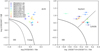 |
Fig. 4. Locations of our targets in the [O III]/Hβ vs [N II]6583/Hα and [O III]/Hβ vs [S II]6716,31/Hα BPT diagrams. Filled circles mark the line ratios obtained from total line fluxes while empty circles are related to the line emission of the broad components only. The solid line in both panels is the Kewley et al. (2001) maximum starburst line. The dashed line in the left panel is the semi-empirical Kauffmann et al. (2003) line and has bee used together with the Kewley et al. (2001) line to separate between line ratios due to photoionisation from stars (HII), AGN or a mixture of both (Comp). The dashed line in the right panel is the Kewley et al. (2006) line separating the AGN between Seyferts and LINERS. |
Although some studies have attempted to determine the ionisation mechanism in a more decisive way using fainter diagnostic emission lines such as [O III]λ4363 Å and HeIIλ4646 Å, the results have proved ambiguous (e.g. Holt et al. 2009), apart perhaps from the case of PKS 1934–63 where evidence for shock ionisation of one of the broader emission-line components was found (Santoro et al. 2018). Reasons for the failure to decisively determine the dominant ionisation mechanism using such methods include (a) the low S/N of the faint diagnostic emission lines and their sensitivity to the accuracy of the subtraction of the underlying continuum; (b) the fact that some of the faint lines are in blends (e.g. [O III]λ4363 Å), with all the attendant problems of degeneracy and the problems this causes for determining individual line fluxes in the face complex, broad line profiles.
Given the issues surrounding the diagnostic line ratio approach to determining the dominant ionisation mechanism, we adopted the alternative method described in Baron et al. (2017), which is based on determining whether the Hβ emission-line luminosity can be reproduced by shock models. Under the assumption that shocks are the dominant ionisation mechanism, we used the location of our galaxies in the two BPT diagrams shown in Fig. 4 to isolate the shock models which produce line ratios within 0.3 dex of those measured for the outflowing gas. We considered pre-computed shock model grids (with and without precursor) taken from MAPPING III and spanning different shock velocities, magnetic parameters and pre-shock gas densities (see Baron et al. 2017, and references therein for details on the models). We then extracted, for each galaxy, the Hβ surface brightness of the selected shock models, and predicted the emitting area that the shocked gas should have assuming that it is uniformly distributed in a thin spherical shell with a filling factor of 100%, and has an Hβ luminosity equal to that measured for the outflowing gas. By comparing the areas and hence radii of the outflows predicted in this way to our observationally determined estimates of the outflow radii (see Sect. 4.2) it was then possible to test whether shock ionisation is feasible.
We found that, if the gas were solely ionised by shocks, we would need to observe outflows extending on scales which are larger then the observed ones by a factor between 1.5 and 5 when looking at the entire sample. This means that for all our targets the observed luminosities are far too high (by a factor between 2 and 25) to be produced purely by shocks alone, and that the dominant ionisation mechanism for the warm outflowing gas is most likely to be AGN photoionisation. We note that this argument is conservative in the sense that the gas is likely to be highly clumped rather than uniformly distributed in the putative shocked shell (i.e. filling factor ≪100%), and that it is also unlikely that any shocked regions are spherical, given the often highly collimated structures visible in emission-line images of CSS and GPS sources (e.g. Fig. 1).
Having established that the ionisation of the outflowing gas is likely to be dominated by AGN photoionisation, we can then estimate the ionisation parameter U – the ratio of the flux density of ionising photons at the face of the ionised cloud to the electron density, normalised by the speed of light. In the following, estimates of the gas ionisation parameter will be used to isolate the fiducial photoionisation models that are required to determine the electron densities and reddening, as shown in Sect. 4.4. Using the calibration reported in Baron & Netzer (2019b, their Eq. (2)) we estimated the ionisation parameter for the total and the outflowing gas by using the [O III]/Hβ and the [N II]6583/Hα line ratios. The derived ionisation parameters are reported in Table 9, while the aforementioned line rations are reported in Table 10. Finally, we emphasise that, while the outflowing gas is likely to be predominantly AGN photoionised rather than shock ionised, this does not rule out shocks as an acceleration mechanism for the gas, since it is plausible that any shock accelerated gas will be photoionised by the AGN as it cools behind the shock front.
Ionisation parameters for the total (Col. 2) and outflowing gas (Col. 3) emission, as determined using the method discussed in Baron & Netzer (2019b).
Logarithmic values of the [O III]/Hβ, [N II]6583/Hα, and [S II]6716+6731/Hα line ratios of the total (Cols. 2, 4, and 6) and outflowing gas (Cols. 3, 5, and 7) emission for the sources in our sample.
4.4. The density and reddening of the outflows
Along with the radius, the electron density is a key parameter for determining the properties of the warm outflowing gas. Here we use the density diagnostic diagram (DDD heareafter) approach, first introduced by Holt et al. (2011), which is sensitive to high electron densities and able to overcome the main limitations of the classical [O II] and/or [S II] line ratios (see Rose et al. 2018; Baron & Netzer 2019b, for a discussion). Our X-shooter data are especially well-suited for this purpose, since, by covering a wide wavelength range, they have allowed us to detect and model all the emission lines needed to measure the trans-auroral [O II] and [S II] line ratios, as defined in the Introduction. By comparing the measured line ratios with those of fiducial photoionisation model grids in the DDD, this method provides estimates of the electron density and the reddening for both the total warm gas emission (i.e. total line fluxes, shown in the left panel of Fig. 5) and, in some cases, for that of the outflowing gas alone (i.e. broad component integrated line fluxes, shown in the right panel of Fig. 5). The trans-auroral line fluxes for the total and outflowing gas emission are reported in Table A.1.
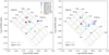 |
Fig. 5. Location of our targets in the density diagnostic diagram (DDD) using the logarithm of the tr[O II] = [O II](3727+3729)/(7318+7319+7330+7331) and of the tr[S II] = [S II](4068+4076)/(6716+6731) line ratios. Error bars have been estimated by propagating the line flux errors while upper/lower limits have been assigned as described in the text; different sources in our sample are marked with different colours as indicated by the legend in the upper right corner of the left panel. For comparison, the DDD also includes the results obtained for the ULIRGs studied by Spence et al. (2018) and Rose et al. (2018) (thin light grey points), two of which also host a compact radio source (thin black points). AGN photoionisation grid models for gas with solar metallicity and two ionisation parameters – log U = −2.5 (light grey colour) and log U = −3.5 (black colour) – are shown with dotted lines. The model grids have been created by fixing the gas metallicity and ionisation parameter while varying the electron density in the interval ne = 100 − 105 cm−3 (from top left to bottom right) and the reddening in the interval E(B − V) = 0 − 1 mag (from top right to bottom left). Left panel: DDD showing the line ratios based on the total line fluxes. Right panel: DDD showing the outflows line ratios determined from the integrated fluxes of broad components of the emission lines. For each galaxy in our sample a solid line connects the line ratios of the total (as shown in the left panel) and outflowing gas emission. |
Some caution is required when using the DDD approach, since the [S II]λλ4069,4076 Å and [O II]λλ7319,7330 Å lines involved in the trans-auroral line ratios arise from transitions with upper energy levels that have higher energies than those involved in the classical [S II] and [O II] ratios. Therefore, trans-auroral ratios are potentially sensitive to the electron temperature of the emitting gas, which in the case of AGN photoionisation, depends on the ionisation parameter U, the ionising continuum shape, and the metallicity. To test the sensitivity of the DDD technique to these parameters, we ran a new set of models using CLOUDY version 17.00 (Ferland et al. 2017). The results of these models are presented in detail in Appendix B together with description of the model set-up, assumptions and range of parameters considered.
Overall, we find that the effect of varying the ionisation parameter, ionising continuum shape and metallicity on the density values determined using the DDD technique is typically at the level of 0.3 dex (factor ∼2) or less. This is illustrated in Fig. 5, where, along with the measured trans-auroral ratios for the CSS and GPS sources, we show two grids of models, one calculated for a high (i.e. log U = −2.5) and the other for a low (log U = −3.5) ionisation parameter and solar metallicity. Both grids were created by varying the electron densities in the interval ne = 100 − 105 cm−3 and the reddening (E(B − V)) between zero and one (adopting the Cardelli et al. 1989 extinction law). The shape of the AGN ionising continuum SED has been chosen by adopting standard assumptions for an AGN and a mean ionising photon energy of 2.56 Ryd (see Appendix B for further details on this choice). It is important to stress that the changes in the positions of DDD grids induced by varying the model parameters are typically within the observational errors estimated for the tr[O II] and [S II] line ratios.
While significant, we emphasise that the level of uncertainty due to varying the model parameters in the DDD approach is far lower than the orders of magnitude uncertainty associated with using the classical [S II] and [O II] ratios or by assuming a low electron density (∼100−200 cm−3), as has been done in some studies.
In order to determine the best possible density and reddening estimates for the outflows, we selected a specific model grid for each object (see Appendix B for details). In the absence of a robust metallicity calibration for AGN-photoionised gas, we chose to use model grids with solar metallicity. On the other hand, we were able to select specific reference model grids (one grid for the total and one for the outflowing gas emission) for each object, based on the ionisation parameter U estimates determined from the line ratios in Sect. 4.3. The electron density and reddening estimates derived by comparing the measured trans-auroral ratios with the object-specific DDD grids are presented in Table 11, together with the respective trans-auroral [O II] and [S II] line ratio measurements.
Trans-auroral [O II] and [S II] ratios, together with the derived density ne and E(B − V) values for the total (Cols. 2–5) and the outflowing (Col. 6–9) gas emission, as determined from the DDD using total line fluxes and broad-component line fluxes, respectively.
By comparing the observed line ratios to the models in Fig. 5, it is clear that most of our targets show high gas electron densities that are sometimes well outside the regime that can be probed by classical density diagnostics. For PKS 1934–63 we find that the gas density of the outflow is higher than that measured using the total line fluxes, in line with the trend seen in Santoro et al. (2018). The same trend is seen also for PKS 0023-26 even though the increase in density is less pronounced and the density values are compatible within the errors. The upper limits and values obtained for the densities of the outflow components (right panel of Fig. 5) suggest a similar behaviour for the remaining sources; however, the sensitivity of our observations does not allow us to confirm this trend in a definitive way. We find no significant difference in the reddening between the total emission and the outflows.
It should be noted that for PKS 0023–26, PKS 1549–79, PKS 1934–63 and PKS 2135–209 we can isolate the emission from the outflowing gas (i.e. the broad kinematic components) in all the trans-auroral lines and thus have a precise estimate of its density. The choice of using only total line fluxes for PKS 1549–79, PKS 2135–209 and PKS 2314+03 gives us a single estimate of the gas density and dust attenuation which can be considered representative of the outflowing gas whose emission prevails in the line profiles (see Sect. 4.1).
As previously mentioned, broad kinematic components are often faint and difficult to detect in the [O II]λλ7319,30 Å and [S II]λλ4069,76 Å doublets. For the targets where this happens we estimate a tr[O II] lower limit and a tr[S II] upper limit by considering the total fluxes of the [O II]λλ7319,30 Å and [S II]λλ4069,76 Å lines respectively as upper limits on the fluxes of the outflowing gas. By construction of the DDD, for these cases we can then extract an upper limit on the density and a lower limit on the reddening of the outflowing gas.
In Fig. 5 we also include sources from the sample of nearby ULIRGs presented in Rose et al. (2018) and Spence et al. (2018), which have been studied using a similar DDD technique. Two of these sources – F 23389+0303N and PKS 1345+12 – are highlighted in the DDD because they are are known to host high power (P1.4 GHz > 1025 W Hz−1), compact (DL < 1 kpc) radio sources associated with their AGN activity, and are therefore similar in their radio properties to the CSS and GPS sources considered in this paper. Clearly, the warm outflows in ULIRGs show a similar range of electron density (3.45 < log(ne cm−3) < 4.75) and reddening (0 < E(B − V) < 1 mag) to those in the CSS and GPS objects. It should be noted that also for F 23389+0303N and PKS 1345+12 the density of the outflowing components are higher then the densities of the whole ISM estimated using total line fluxes. In Appendix C we discuss the comparison between our measurements and (i) the dust attenuation estimated via the classical Hα/Hβ Balmer decrement, (ii) the gas densities estimated using an alternative method proposed by Baron & Netzer (2019b).
4.5. AGN bolometric luminosties
The bolometric luminosity (LBOL) provides a key indication of the overall level of radiative AGN activity, and in the following will be compared with the outflow kinetic power, in order to derive the feedback efficiency – an important parameter for comparison with AGN feedback models. Determinations of LBOL using optical continuum measurements are challenging for most of the objects in our sample, which are Type 2 AGN, because the direct AGN continuum is blocked out by circum-nuclear dust. Even in wavelength regions that are less strongly affected by dust extinction, the direct emission from the energy-generating regions close to the AGN of the CSS and GPS sources is potentially contaminated by non-thermal emission from the radio sources (mid-to-far infrared and X-ray wavelength regions: Dicken et al. 2008, and in prep.; Mingo et al. 2014) and/or emission from star formation regions (particularly mid-to-far infrared: Dicken et al. 2008, 2012). Therefore, we must rely on emission-line indicators of LBOL.
We considered two emission-line based bolometric luminosity indicators. The first uses the total [O III]λ5007 Å luminosity (L[OIII]) along with the L[OIII]-to-LBOL correction factor of 3500 derived by Heckman et al. (2004). We note that this method uses L[OIII] values that have not been corrected for dust extinction. In contrast, the second indicator – developed by Lamastra et al. (2009) – uses L[OIII] values corrected for dust extinction, as well as luminosity-dependent correction factors. When applying this latter method to our CSS and GPS sample, the extinction correction was performed using the E(B − V) values measured as part of the DDD analysis described above. The results are shown in Table 12, from which it is clear that the bolometric luminosities derived using the Heckman et al. (2004) method are systematically higher, by typically a factor of a few but up to a factor of 10, than those derived using the Lamastra et al. (2009) method.
Total [O III]5007 Å line fluxes (Col. 2), the [O III] observed (Col. 3) and dust corrected (Col. 4) luminosities, and the AGN bolometric luminosities calculated following the Lamastra et al. (2009) (Col. 5) and the Heckman et al. (2004) (Col. 6) calibrations.
Both the above methods assume that the covering factor of the [O III]-emitting gas is the same for all AGN of a given LBOL. However, this is not necessarily the case, and indeed there are reasons to believe that covering factor may in reality be higher in CSS and GPS than in typical AGN: first, because these are young radio sources in an early stage of evolution, the circum-nuclear regions may not yet have been swept clear by AGN-induced outflows (Tadhunter et al. 1999), thus leading to larger amounts of gas in the narrow-line region (NLR; see discussion in Tadhunter et al. 2001); second, there is evidence from mid-to-far infrared and optical observations that CSS and GPS sources have higher rates of star formation than more typical, extended radio galaxies (Tadhunter et al. 2011; Dicken et al. 2014), thus suggesting more gas-rich near-nuclear environments that could, potentially, also be associated with high NLR covering factors.
In this context, it is interesting to note that if we attempt to estimate the gas electron densities following the technique of Baron & Netzer (2019b), based on measurements of ionisation parameter U, AGN bolometric luminosity LBOL, and radius r (N.B. ne ∝ LBOL/(r2U)), the derived values are systematically higher than those we derived using the DDD technique above (see Appendix C for a detailed discussion). This applies to densities derived using both the Heckman et al. (2004) and Lamastra et al. (2009)LBOL estimates, but the discrepancy is higher in Heckman et al. (2004) case. Part of the reason for this apparent discrepancy might be that, in making this calculation, we have not corrected our radius estimates for line-of-sight projection effect. However, assuming that the radio sources are oriented at random, the mean angle (θ) of the radio axis relative to the line of sight is expected to be θ ∼ 57.3°. The implied mean correction factor is then 1.8 for r, or 3.4 for r2, which is not sufficient alone to explain the density discrepancy. One way to bring the density estimates fully into agreement would be to decrease the LBOL values; this provides indirect evidence that the LBOL values derived using both the emission-line methods may be over-estimated by a factor of 2 or more. As we discuss in detail in Appendix C, alternative explanations for the discrepancy in terms of U being overestimated from the line ratios, or the trans-auroral [S II] and [O II] lines being emitted by lower density clouds situated at larger radii than those emitting [O III] and Hβ lines, are less plausible.
In the following sections we will use the lower LBOL values derived via the Lamastra et al. (2009) approach, since they take into account dust extinction, and we feel that they are more likely to reflect the true LBOL values, given the above discussion. However, it is important to bear in mind that even these lower LBOL values may represent over-estimates if the covering factor of the [O III]-emitting gas is substantially higher in CSS and GPS sources than in the general population of AGN used to derive the calibration.
5. General outflow properties
5.1. Warm gas masses
Having derived the main basic properties of the outflows in our galaxies (e.g. their electron densities, extents and kinematic features), we now characterise the outflows in terms of their masses and kinetic powers, in order to asses the effect that the AGN feedback has on the host galaxies. The warm ionised gas masses associated with both the total emission and the outflows have been calculated using the following equation:
where L(Hβ) is the intrinsic Hβ luminosity (i.e. corrected for dust extinction), mp is the proton mass, ne is the gas electron density,  is the effective Hβ recombination coefficient (taken as 3.03 × 10⁻¹⁴ cm3 s−1 for case B, Te = 104 K, ne = 102 cm−3; Osterbrock & Ferland 2006), νHβ is the frequency of the Hβ, and h is the Planck constant. To obtain these estimates we used the intrinsic Hβ luminosities (LHβintr) reported in Table 13 and the DDD-derived electron densities reported in Table 11. When calculating the intrinsic Hβ luminosities we used the redshifts extracted from the stellar population fitting (see Table 4) to estimate the target distances, and the DDD-derived E(B − V) values (see Table 11) to correct for the dust.
Hβ flux (Col.2), the observed and intrinsic Hβ luminosity of the total (Cols. 3–4) and the outflowing gas (Cols. 5–7).
As can be seen in Table 14 we find that the fraction of the total warm gas mass in the outflow varies considerably from galaxy to galaxy, ranging from ∼20% up to ∼70%. However, for three of our targets – PKS 1549–79, PKS 2135–209 and PKS 2314+03 – the outflowing gas fraction is 100% due to the fact that the emission line profiles are dominated by the outflowing gas components, and all the kinematic components used to model the line emission are considered broad according to our criteria.
Masses of the gas emitting the total (MT) and outflow (Mout) emission in units of solar mass, and the fraction of the masses associated with the outflowing gas expressed as a percentage of the total gas mass.
5.2. Mass outflow rates, kinetic powers, and AGN feedback efficiencies
In this section we use the outflow masses, radii and kinematic properties, along with the AGN bolometric luminosities to finally determine the mass outflow rates Ṁ, outflow kinetic powers Ė and AGN feedback efficiencies F. Following Rose et al. (2018) we use the equations listed below:

where r is the radius of the outflow and LBOL is the AGN blometric luminosity.
In order to assign values to the vout and the σ terms we use the kinematic properties of our outflows reported in Table 5 and adopt two different approaches. The so-called classical approach assumes that the centroid velocity of an emission associated with the outflowing gas represents the true velocity of the outflow, and its broadening is due to the intrinsic velocity dispersion in each part of the outflow. In this case, we set vout = v and σ = FWHM/2.355. This classical approach does not explicitly account for line-of-sight projection effects. Therefore, we also consider the less conservative approach (hereafter referred to as the vmax approach) discussed in Rose et al. (2018). This attempts to account for projection effects by setting vout = vmax and σ = 0, and assumes that the broadening of the emission lines is entirely due to the different projections of the velocity vectors of the outflowing gas, rather than localised velocity dispersion.
Table 15 reports the Ṁ, Ė and F we obtain by using the equations above and following the two approaches. It appears clear that by using the vmax approach the kinetic powers and the AGN feedback efficiencies, which are proportional to the mass outflow rates Ṁ, typically increase by one order of magnitude with respect to the classical approach. The target that is most affected is PKS 0252–71, with a change of two orders of magnitude for both these quantities, mainly due to the large difference between v and vmax.
Mass outflow rates Ṁ, the outflow kinetic powers Ė, and the AGN feedback efficiencies F for the targets of our sample, as estimated by following the classical (Cols. 2–4) and the vmax (Cols. 5–7) approaches.
In the following and in Sect. 6 we will discuss only the estimates that have been obtained with the vmax approach. As already noted, this approach is thought to overcome some of the limitations due to projection effects and therefore gives a more realistic characterisation of the outflows properties. Moreover, since similar approaches have been widely used in the literature, it allows us to make a fair comparison with previous outflow studies.
For our sample of compact radio galaxies we find mass outflow rates in the range 0.4 < Ṁ < 20 M⊙ yr−1. The highest values are found for PKS 1549–79, PKS 2135–209 and PKS 2314+03 where we consider that all the line-emitting gas is outflowing. The AGN feedback efficiencies are remarkably small and in general lower then 1%, ranging from a minimum of 0.002% to a maximum of 1%3 in agreement with what has been found by some of the more recent studies on outflows that, similarly to ours, adopted density diagnostics sensitive to high densities, thus overcoming the limitations of the classical [O II] and [S II] line ratios (e.g. Spence et al. 2018; Rose et al. 2018; Baron & Netzer 2019b; Davies et al. 2020). In particular, we highlight that the general warm outflow properties of the CSS and GPS sources are comparable with those derived by Rose et al. (2018) and Spence et al. (2018) using similar techniques for nearby ULIRGs with optical AGN nuclei (0.07 < Ṁ < 20 M⊙ yr−1; 0.03 < F < 2.5%).
6. Discussion
In this section we compare the properties of the outflows detected in our sample of compact radio sources with those of outflows in other AGN samples collected from the literature. These samples are described below to highlight the effect that alternative electron density estimators can have on the final numbers quantifying the mass outflow rates, and more in general, the AGN feedback efficiency.
The mass outflow rates and kinetic energies we collected for the comparison samples have been calculated under the assumption that the true velocity of the outflowing gas is the maximum velocity detected in the wings of the emission line profiles – similar to what we call the vmax approach in Sect. 5. It should be noted, however, that the way vmax has been calculated differs in detail from sample to sample, and more details are given below. We will compare our results with those for the outflows included in the Fiore et al. (2017), Rose et al. (2018), Spence et al. (2018), Baron & Netzer (2019b), and Davies et al. (2020) studies described in the following.
The Fiore et al. (2017) study includes molecular (CO and OH) and warm ionised outflow results for AGN covering a wide redshift range 0.003 < z < 3.5. It concerns an heterogeneous collection of outflows from the literature that were selected to have a good estimate (or a robust limit) of the spatial extent of the high velocity gas involved in the outflow. For the ionised gas outflows the authors re-computed the outflow properties from the original data, homogenizing the estimates of the outflow velocities and densities. In particular, following Rupke & Veilleux (2013), they defined vmax = vbroad + 2σbroad, where vbroad and σbroad are respectively the centroid velocity (with respect to the systemic velocity) and the σ of the broad Gaussian component used to model the outflow. The electron densities of the outflowinig material were assumed to be ne = 200 cm−3 in the absence of more accurate measurements.
The Rose et al. (2018) and Spence et al. (2018) studies includes warm outflows in a 90% complete sample of 15 local (z < 0.175) ULIRGs with nuclear AGN activity detected at optical wavelengths. They consider rapidly evolving galaxies in the local universe that are hosting and AGN and are, in most cases, involved in a merger event. It is the most directly comparable study to the current one, since the methods used to determine outflow radii and densities are similar to those we used for the CSS and GPS sources. In particular, the DDD approach was used to determine the electron densities of the outflows. As already noted above, two of these ULIRGs – F 23389+0303N and PKS 1345+12 – have radio properties that are similar to the CSS and GPS sources in our sample.
The Baron & Netzer (2019b) and the Davies et al. (2020) studies include warm ionised outflows of low-to-moderate luminosity AGN in the local universe (z < 0.15). These outflows are mainly associated with type II AGN in the local universe with low-to-moderate luminosities. The Baron & Netzer (2019b) sample includes 234 outflows for which  , where vshift is the velocity shift of the broad emission line centroid with respect to the narrow lines, and σ is the velocity dispersion of the broad emission lines (following Karouzos et al. 2016), and the gas density has been estimated using a novel method based on the ionisation parameters and sensitive to high densities. The Davies et al. (2020) sample includes 11 outflows for which the outflows velocity is set equal to v98, the absolute value of the velocity above (or below) which 98% of the line flux is contained, and outflow gas densities have been obtained following the Baron & Netzer (2019b) prescriptions.
From the description of the selected comparison samples is clear that we are here comparing AGN at different redshifts and hosted by galaxies at different evolutionary stages. In addition, we are not making a distinction between the AGN mode (jet mode vs quasar mode) that is driving the outflows. Most of the outflows in the comparison samples are claimed to be driven by the central AGN radiation pressure (so-called AGN winds), while for our sample we have indications that the radio jets can be the main driver. However, with the available data it is often not possible to draw a clear demarcation line: some of the galaxies in the comparison samples host radio sources (e.g. the sources of the Nesvadba et al. 2008 study included in the Fiore et al. 2017 sample) that are known/might contribute to driving the outflows, even at relatively moderate radio powers (e.g. IC 5063 Tadhunter et al. 2014; Morganti et al. 2015) and, on the other hand, we cannot rule out radiation pressure playing a role in driving the outflows in the CSS and GPS sources in our sample. Multi-wavelength high spatial resolution data allowing detailed comparison of the radio and warm gas morphologies are usually the best way to discriminate between the AGN feedback modes, but unfortunately they are available for only a handful of sources. The comparison we present in this section is thus meant to show the overall effect that the AGN feedback (operated by both radio jets and radiation pressure) can have on the ISM of the host galaxies. Therefore, it is important to bear in mind that some of the differences between the outflow properties that we are going to discuss can be reasonably attributed to the different nature of the AGN we are comparing.
Figure 6 shows the outflow velocity as a function of the AGN bolometric luminosity for our sample and the comparison samples. It is notable that, although CSS and GPS, and ULIRG samples have intermediate bolometric luminosities, they both include objects whose extreme velocities are characteristic of the outflows hosted in the most luminous AGN in the Fiore et al. (2017) sample. By considering their molecular and ionised gas outflows, Fiore et al. (2017) claim to find a trend of increasing outflow velocity with increasing AGN bolometric luminosity (i.e. the dashed line in Fig. 6 can be used as a reference). However, considering the Fiore et al. (2017) sample along with the GPS/CSS and other comparison samples included in the plot, the trend appears less clear.
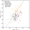 |
Fig. 6. AGN bolometric luminosity as a function of the outflow velocity, vout for our sample (back filled points) and the comparison samples (see legend in the upper left). To distinguish them from the rest of the comparison sample, the markers of the two ULIRGs hosting a compact radio source have a black edge colour. The black dashed line marks a |


In Fig. 7 we show the mass outflow rate (left panel) and kinetic power (right panel) as a function of the AGN bolometric luminosity for our sample and the comparison samples, reproducing Fig. 1 presented in Fiore et al. (2017). It is important to emphasise that the way the density of the outflowing gas has been estimated plays a crucial role in the interpretation of this figure, as also stressed in Spence et al. (2018) and Davies et al. (2020). Apart from the ionised gas outflows in the sample of Fiore et al. (2017), for which the electron density has been assumed to be ne = 200 cm−3, the electron densities of all the outflows presented in the Fig. 7 have been estimated using diagnostics that are sensitive to the high density regime. Despite this, we choose to show the best fit relation found for the ionised gas outflows by Fiore et al. (2017) (dashed black line) for its importance as a reference point in the current literature, and to stress the differences that a more precise electron density estimate can make. In fact, in Fig. 7 is also shown how assuming the same gas density of ne = 200 cm−3 (black empty circles) as Fiore et al. (2017) increases the Ṁ and the Ė estimates for our warm outflows by one or two orders of magnitude. This would place our warm ionised outflows among those with the highest mass outflow rates and kinetic energies at a given AGN bolometric luminosity, and in some cases make them similar to the massive molecular gas outflows in the sample of Fiore et al. (2017). An analogous behaviour is expected for the outflows of the remaining comparison samples, as noted in the original studies.
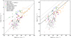 |
Fig. 7. Mass outflow rate (left panel) and kinetic power of the outflow (right panel) as a function of the AGN bolometric luminosity for our sample (black points) and the comparison samples (see legend in the upper left of the left panel). To distinguish them from the rest of the comparison sample, the markers of the two ULIRGs hosting a compact radio source have a black edge colour. To enable a fair comparison with the ionised gas outflows of Fiore et al. (2017) we also assumed an outflow gas density of ne = 200 cm−3 for all our targets (black empty circles). The CO outflow detected in PKS 1549–79 by Oosterloo et al. (2019) has been also included in this plot using our estimate of the source LBOL, a green dashed vertical line connects the warm ionised and the molecular outflow Ṁ and Ė values for this object to highlight the differences between the outflows properties in the two gas phases. The dotted and dashed black lines in the left panel represent the best fit relations found by Fiore et al. (2017) for the molecular gas and ionised gas outflows, respectively. The dotted, dashed and solid black lines in the right panel mark the correlations Ė = 1, 0.1, 0.01 LBOL. |
Conversely, we argue that more precise estimates of the outflow densities would potentially bring the warm ionised outflows of Fiore et al. (2017) down to lower Ṁ and Ė values (see Davies et al. 2020, who first tried to quantify the expected shift). Considering this effect, we predict that the current compilation of sources shown in Fig. 7 would result in a correlation between Ṁ and LBOL with a flatter slope than that found by Fiore et al. (2017) (i.e. the dashed black line in Fig. 7). Similarly, most of the Fiore et al. (2017) warm ionised outflows in the right panel of Fig. 7 would then lie below the solid line marking an AGN feedback efficiency of F = 1%, consistent with the results for our sample and the remaining comparison samples, but well below the F ∼ 5 – 10% required by some AGN feedback models (e.g. Silk & Rees 1998; Fabian 1999; Di Matteo et al. 2005).
Interestingly, the CSS, GPS, and ULIRG objects also show evidence for higher mass outflow rates, kinetic powers and feedback efficiencies in their warm outflows than objects of similar AGN bolometric luminosity in the Baron & Netzer (2019b) and Davies et al. (2020) samples. This may reflect the fact that the AGN in CSS, GPS, and the ULIRG objects have been triggered in unusually gas-rich environments, so that the drivers of their warm outflows, whether relativistic radio jets (CSS, GPS, and some ULIRGs) or hot, radiation-driven winds (most ULIRGs), are able to couple more effectively with the cooler phases of the ISM.
It is important to emphasise that the scatter of the points in these plots and/or the lack of correlations for single samples such as ours, spanning only few orders of magnitudes in LBOL, is not surprising. As stressed by Zubovas (2018) the evolutionary times of outflows are longer then the AGN activity event (at most 106 yr for young jets as we consider here) that inflates them (typically by one order of magnitude, see King et al. 2011), and for this reason a significant scatter is expected between quantities measuring the properties of outflows and the level of the current AGN activity in the nuclear regions of the host galaxies.
Finally, we stress that we only considered the warm ionised outflows in the CSS and GPS sources, and that significantly higher mass outflow rates and kinetic powers may be associated with the neutral (e.g. Morganti et al. 2005; Rupke et al. 2005) and molecular (Cicone et al. 2014; Morganti et al. 2015) gas phases in the outflows (e.g. see the green points representing the molecular outflows taken from the Fiore et al. 2017 in Fig. 7). Therefore, the total feedback efficiencies may be higher that those we calculated for the warm outflowing gas phase alone. This is illustrated by the case of one of the objects in our sample – PKS 1549–79 – which has recently been observed using ALMA at high resolution in the CO(1–0) and CO(2–3) molecular lines (Oosterloo et al. 2019). The observations detect a compact, high velocity molecular outflow whose mass outflow rate (Ṁmol = 650 M⊙ yr−1), kinetic power (Ėmol = 2.3 × 1044 erg s−1) and feedback efficiency (Fmol ∼ 3%) are more than an order of magnitude higher than those we measure for the warm outflow in the same object (Ṁwarm = 9 M⊙ yr−1, Ėwarm = 1.1 × 1043 erg s−1; Fwarm ∼ 0.2% – see Fig. 7).
7. Conclusions
We used VLT/X-shooter and HST/ACS data to investigate the warm, AGN-driven outflows in a sample of nine CSS and GPS objects whose AGN have intermediate bolometric luminosities (in the interval 1044 − 46 erg s−1). This class of galaxies is known to host young and powerful radio sources whose jets are expanding through the surrounding ISM and interacting with it. The signs of this interaction are detected in the form of gas outflows in different gas phases, and help shed light on the AGN feedback process and some of the still open question surrounding this topic (e.g. the typical mass content of outflows and the overall AGN feedback efficiency). Our main results are as follows.
-
Kinematics. The emission line profiles clearly indicate very disturbed gas kinematics and, when modelled, show the presence of outflows reaching velocities ranging from ∼600 km s−1 up to 2000 km s−1 (i.e. vmax in Table 6) for all the galaxies in our sample. Many of the outflows we detect have extreme kinematic features compared to the outflows found in more extended radio sources with comparable radio powers and redshifts, or radio-quiet AGN of similar bolometric luminosities, confirming what has been found in the literature (Holt et al. 2008).
-
Spatial extents. The spatial extents of the warm ionised outflows (0.06 < r < 1.9 kpc) agree well with those of the radio sources, as measured using the separation of the radio lobes in high resolution VLBI radio images (see Table 7); in some cases the emission-line structures are also closely aligned with the radio axes. This supports the idea that the so-called jet mode feedback is in action in compact radio sources, and hence the expansion of the radio jets is likely to be the dominant driver of the outflows we observe, similar to what has been found in other studies (e.g. Tadhunter et al. 2014).
-
Densities. The warm outflows include dense (log(ne cm−3)∼3 − 4.8) gas components that are often denser than the gas of the host galaxy ISM, possibly indicating gas compression operated, at some level, by the AGN feedback.
-
Gas masses. The outflows comprise 20−70% of the total host galaxy warm ISM mass sampled by our spectroscopic slits, while the mass outflow rates cover the range 0.4 < Ṁ < 20 M⊙ yr−1.
-
Feedback efficiency. The AGN feedback efficiencies F for the warm outflows of our sample are relatively low: usually below 1%, and covering the range 0.002 < F < 1%.
To put our study in a broader context, we compared our results for the CSS and GPS sources with those for an heterogeneous collection of warm outflows (claimed to be mainly driven by the AGN quasar mode) taken from the literature. The results of this comparison further emphasise the sensitivity of the derived outflow properties (e.g. masses, energetics, feedback efficiency) to the precision with which the electron densities are measured.
In all aspects, the properties of warm outflows we detect in the CSS and GPS sources are strikingly similar to those measured using the same techniques for nearby ULIRGs with nuclear AGN activity, despite the fact that the dominant outflow driving mechanisms are likely to be different in the two types of objects. This suggests that the feedback effect of the relativistic jets on kpc-scales can be as effective as that of the hot winds driven by the radiation of the AGN, in line with the predictions of recent numerical simulations (e.g. Wagner et al. 2013; Mukherjee et al. 2016, 2018).
Although we are aware of the caveats to consider when comparing the AGN feedback efficiency derived from observations to the prescription of cosmological models (see Harrison et al. 2018), we note here that all the latest results from studies attempting to improve the measurements of the warm outflow gas density indicate that the AGN feedback efficiencies are far below the 5−10% expected by classical AGN feedback models (such as Fabian 1999; Di Matteo et al. 2005), and in general lower then those that have been typically estimated for warm ionised gas outflows in the literature (Fiore et al. 2017). This puts the accent on the need for further precise measurements of the basic outflows parameters such as the gas density, as well as more sophisticated AGN feedback models for both the jet-mode and the quasar-mode (see e.g. Cielo et al. 2018; Weinberger et al. 2018), in order to fully understand the role of AGN-driven outflows in the galaxy evolution context.
In this work we did not consider constant pressure clouds as they are expected to give similar line ratios and luminosities to constant density clouds, for the ionisation parameters considered here. See Baron & Netzer (2019b) for additional details.
Acknowledgments
The authors thank the anonymous referee for their useful comments that improved the clarity of the paper. FS and CT acknowledge support from STFC. The research leading to these results has received funding from the European Research Council under the European Union’s Seventh Framework Programme (FP/2007-2013)/ERC Advanced Grant RADIOLIFE-320745. Based on observations collected at the European Organisation for Astronomical Research in the Southern Hemisphere under ESO programmes 060.A-9412(A) and 87.B-0614A. Based on observations taken with the NASA/ESA Hubble Space Telescope, obtained at the Space Telescope Science Institute (STScI), which is operated by AURA, Inc. for NASA under contract NAS5-26555. This research has made use of the NASA/IPAC Extragalactic Database (NED) which is operated by the Jet Propulsion Laboratory, California Institute of Technology, under contract with the National Aeronautics and Space Administration. The python packages PyNeb (https://pypi.org/project/PyNeb/, Luridiana et al. 2013) and uncertainties (https://uncertainties-python-package.readthedocs.io/en/latest/index.html) have been used throughout this work to respectively derive dust corrections and propagate the errors.
References
- An, T., & Baan, W. A. 2012, ApJ, 760, 77 [Google Scholar]
- Audibert, A., Combes, F., García-Burillo, S., et al. 2019, A&A, 632, A33 [NASA ADS] [CrossRef] [EDP Sciences] [Google Scholar]
- Axon, D. J., Capetti, A., Fanti, R., et al. 2000, AJ, 120, 2284 [NASA ADS] [CrossRef] [Google Scholar]
- Baldwin, J. A., Phillips, M. M., & Terlevich, R. 1981, PASP, 93, 5 [NASA ADS] [CrossRef] [EDP Sciences] [Google Scholar]
- Baron, D., & Netzer, H. 2019a, MNRAS, 482, 3915 [NASA ADS] [CrossRef] [Google Scholar]
- Baron, D., & Netzer, H. 2019b, MNRAS, 486, 4290 [NASA ADS] [CrossRef] [Google Scholar]
- Baron, D., Netzer, H., Poznanski, D., Prochaska, J. X., & Förster Schreiber, N. M. 2017, MNRAS, 470, 1687 [CrossRef] [Google Scholar]
- Baron, D., Netzer, H., Prochaska, J. X., et al. 2018, MNRAS, 480, 3993 [CrossRef] [Google Scholar]
- Batcheldor, D., Tadhunter, C., Holt, J., et al. 2007, ApJ, 661, 70 [NASA ADS] [CrossRef] [Google Scholar]
- Benson, A. J., Bower, R. G., Frenk, C. S., et al. 2003, ApJ, 599, 38 [NASA ADS] [CrossRef] [Google Scholar]
- Best, P. N., Longair, M. S., & Rottgering, H. J. A. 1996, MNRAS, 280, L9 [NASA ADS] [CrossRef] [Google Scholar]
- Best, P. N., Kauffmann, G., Heckman, T. M., et al. 2005, MNRAS, 362, 25 [NASA ADS] [CrossRef] [Google Scholar]
- Bower, R. G., Benson, A. J., Malbon, R., et al. 2006, MNRAS, 370, 645 [NASA ADS] [CrossRef] [Google Scholar]
- Bruzual, G., & Charlot, S. 2003, MNRAS, 344, 1000 [NASA ADS] [CrossRef] [Google Scholar]
- Cappellari, M. 2017, MNRAS, 466, 798 [NASA ADS] [CrossRef] [Google Scholar]
- Cappellari, M., & Emsellem, E. 2004, PASP, 116, 138 [NASA ADS] [CrossRef] [Google Scholar]
- Cardelli, J. A., Clayton, G. C., & Mathis, J. S. 1989, ApJ, 345, 245 [NASA ADS] [CrossRef] [Google Scholar]
- Cicone, C., Maiolino, R., Sturm, E., et al. 2014, A&A, 562, A21 [NASA ADS] [CrossRef] [EDP Sciences] [Google Scholar]
- Cielo, S., Bieri, R., Volonteri, M., Wagner, A., & Dubois, Y. 2018, MNRAS, 477, 1336 [NASA ADS] [CrossRef] [Google Scholar]
- Clark, N. E., Axon, D. J., Tadhunter, C. N., Robinson, A., & O’Brien, P. 1998, ApJ, 494, 546 [NASA ADS] [CrossRef] [Google Scholar]
- Comerford, J. M., Negus, J., Müller-Sánchez, F., et al. 2020, ApJ, 901, 159 [CrossRef] [Google Scholar]
- Davies, R., Baron, D., Shimizu, T., et al. 2020, MNRAS, 498, 4150 [Google Scholar]
- de Vries, W. H., O’Dea, C. P., Baum, S. A., et al. 1997, ApJS, 110, 191 [NASA ADS] [CrossRef] [Google Scholar]
- Dicken, D., Tadhunter, C., Morganti, R., et al. 2008, ApJ, 678, 712 [NASA ADS] [CrossRef] [Google Scholar]
- Dicken, D., Tadhunter, C., Axon, D., et al. 2009, ApJ, 694, 268 [NASA ADS] [CrossRef] [Google Scholar]
- Dicken, D., Tadhunter, C., Axon, D., et al. 2012, ApJ, 745, 172 [NASA ADS] [CrossRef] [Google Scholar]
- Dicken, D., Tadhunter, C., Morganti, R., et al. 2014, ApJ, 788, 98 [NASA ADS] [CrossRef] [Google Scholar]
- Di Matteo, T., Springel, V., & Hernquist, L. 2005, Nature, 433, 604 [NASA ADS] [CrossRef] [PubMed] [Google Scholar]
- Fabian, A. C. 1999, MNRAS, 308, L39 [NASA ADS] [CrossRef] [Google Scholar]
- Ferland, G. J., Chatzikos, M., Guzmán, F., et al. 2017, Rev. Mex. Astron. Astrofis., 53, 385 [NASA ADS] [Google Scholar]
- Fiore, F., Feruglio, C., Shankar, F., et al. 2017, A&A, 601, A143 [NASA ADS] [CrossRef] [EDP Sciences] [Google Scholar]
- Fischer, T. C., Kraemer, S. B., Schmitt, H. R., et al. 2018, ApJ, 856, 102 [NASA ADS] [CrossRef] [Google Scholar]
- Gelderman, R., & Whittle, M. 1994, ApJS, 91, 491 [NASA ADS] [CrossRef] [Google Scholar]
- Giroletti, M., & Polatidis, A. 2009, Astron. Nachr., 330, 193 [NASA ADS] [CrossRef] [Google Scholar]
- Greene, J. E., Zakamska, N. L., & Smith, P. S. 2012, ApJ, 746, 86 [NASA ADS] [CrossRef] [Google Scholar]
- Harrison, C. M., Alexander, D. M., Swinbank, A. M., et al. 2012, MNRAS, 426, 1073 [NASA ADS] [CrossRef] [Google Scholar]
- Harrison, C., Alexander, D., Mullaney, J., & Swinbank, A. 2014, MNRAS, 441, 3306 [Google Scholar]
- Harrison, C. M., Costa, T., Tadhunter, C. N., et al. 2018, Nat. Astron., 2, 198 [NASA ADS] [CrossRef] [Google Scholar]
- Heckman, T. M., Kauffmann, G., Brinchmann, J., et al. 2004, ApJ, 613, 109 [NASA ADS] [CrossRef] [Google Scholar]
- Holt, J., Tadhunter, C., Morganti, R., et al. 2006, MNRAS, 370, 1633 [NASA ADS] [CrossRef] [Google Scholar]
- Holt, J., Tadhunter, C. N., & Morganti, R. 2008, MNRAS, 387, 639 [NASA ADS] [CrossRef] [Google Scholar]
- Holt, J., Tadhunter, C. N., & Morganti, R. 2009, MNRAS, 400, 589 [NASA ADS] [CrossRef] [Google Scholar]
- Holt, J., Tadhunter, C. N., Morganti, R., & Emonts, B. H. C. 2011, MNRAS, 410, 1527 [NASA ADS] [Google Scholar]
- Hopkins, P. F., Richards, G. T., & Hernquist, L. 2007, ApJ, 654, 731 [NASA ADS] [CrossRef] [Google Scholar]
- Husemann, B., Scharwächter, J., Bennert, V. N., et al. 2016, A&A, 594, A44 [NASA ADS] [CrossRef] [EDP Sciences] [Google Scholar]
- Husemann, B., Bennert, V. N., Jahnke, K., et al. 2019a, ApJ, 879, 75 [NASA ADS] [CrossRef] [Google Scholar]
- Husemann, B., Scharwächter, J., Davis, T. A., et al. 2019b, A&A, 627, A53 [NASA ADS] [CrossRef] [EDP Sciences] [Google Scholar]
- Inskip, K. J., Tadhunter, C. N., Morganti, R., et al. 2010, MNRAS, 407, 1739 [NASA ADS] [CrossRef] [Google Scholar]
- Jarvis, M. E., Harrison, C. M., Thomson, A. P., et al. 2019, MNRAS, 485, 2710 [NASA ADS] [CrossRef] [Google Scholar]
- Karouzos, M., Woo, J.-H., & Bae, H.-J. 2016, ApJ, 833, 171 [NASA ADS] [CrossRef] [Google Scholar]
- Kauffmann, G., Heckman, T. M., Tremonti, C., et al. 2003, MNRAS, 346, 1055 [Google Scholar]
- Kewley, L. J., Heisler, C. A., Dopita, M. A., & Lumsden, S. 2001, ApJS, 132, 37 [NASA ADS] [CrossRef] [Google Scholar]
- Kewley, L., Groves, B., Kauffmann, G., & Heckman, T. 2006, MNRAS, 372, 961 [NASA ADS] [CrossRef] [Google Scholar]
- King, A., & Pounds, K. 2015, ARA&A, 53, 115 [Google Scholar]
- King, A. R., Zubovas, K., & Power, C. 2011, MNRAS, 415, L6 [NASA ADS] [CrossRef] [Google Scholar]
- Labiano, A. 2008, A&A, 488, L59 [NASA ADS] [CrossRef] [EDP Sciences] [Google Scholar]
- Lamastra, A., Bianchi, S., Matt, G., et al. 2009, A&A, 504, 73 [NASA ADS] [CrossRef] [EDP Sciences] [Google Scholar]
- Liu, G., Zakamska, N. L., Greene, J. E., Nesvadba, N. P. H., & Liu, X. 2013, MNRAS, 436, 2576 [NASA ADS] [CrossRef] [Google Scholar]
- Luridiana, V., Morisset, C., & Shaw, R. A. 2013, Astrophysics Source Code Library [record ascl:1304.021] [Google Scholar]
- Marconi, A., Risaliti, G., Gilli, R., et al. 2004, MNRAS, 351, 169 [Google Scholar]
- Markwardt, C. B. 2009, in Astronomical Data Analysis Software and Systems XVIII, eds. D. A. Bohlender, D. Durand, & P. Dowler, ASP Conf. Ser., 411, 251 [Google Scholar]
- May, D., Rodríguez-Ardila, A., Prieto, M. A., et al. 2018, MNRAS, 481, L105 [CrossRef] [Google Scholar]
- McCarthy, P. J., van Breugel, W., Spinrad, H., & Djorgovski, S. 1987, ApJ, 321, L29 [NASA ADS] [CrossRef] [Google Scholar]
- McNamara, B. R., & Nulsen, P. E. J. 2012, New J. Phys., 14, 055023 [NASA ADS] [CrossRef] [Google Scholar]
- Mingo, B., Hardcastle, M. J., Croston, J. H., et al. 2014, MNRAS, 440, 269 [NASA ADS] [CrossRef] [Google Scholar]
- Molyneux, S. J., Harrison, C. M., & Jarvis, M. E. 2019, A&A, 631, A132 [CrossRef] [EDP Sciences] [Google Scholar]
- Morganti, R., Killeen, N. E. B., & Tadhunter, C. N. 1993, MNRAS, 263, 1023 [NASA ADS] [CrossRef] [Google Scholar]
- Morganti, R., Oosterloo, T. A., Reynolds, J. E., Tadhunter, C. N., & Migenes, V. 1997, MNRAS, 284, 541 [NASA ADS] [CrossRef] [Google Scholar]
- Morganti, R., Oosterloo, T., Tadhunter, C. N., et al. 1999, A&AS, 140, 355 [NASA ADS] [CrossRef] [EDP Sciences] [Google Scholar]
- Morganti, R., Tadhunter, C. N., & Oosterloo, T. A. 2005, A&A, 444, L9 [NASA ADS] [CrossRef] [EDP Sciences] [Google Scholar]
- Morganti, R., Holt, J., Saripalli, L., Oosterloo, T. A., & Tadhunter, C. N. 2007, A&A, 476, 735 [NASA ADS] [CrossRef] [EDP Sciences] [Google Scholar]
- Morganti, R., Oosterloo, T., Oonk, J. B. R., Frieswijk, W., & Tadhunter, C. 2015, A&A, 580, A1 [NASA ADS] [CrossRef] [EDP Sciences] [Google Scholar]
- Mukherjee, D., Bicknell, G. V., Sutherland, R., & Wagner, A. 2016, MNRAS, 461, 967 [NASA ADS] [CrossRef] [Google Scholar]
- Mukherjee, D., Bicknell, G. V., Wagner, A. E. Y., Sutherland, R. S., & Silk, J. 2018, MNRAS, 479, 5544 [NASA ADS] [CrossRef] [Google Scholar]
- Mullaney, J. R., Alexander, D. M., Fine, S., et al. 2013, MNRAS, 433, 622 [NASA ADS] [CrossRef] [Google Scholar]
- Murgia, M., Fanti, C., Fanti, R., et al. 1999, A&A, 345, 769 [NASA ADS] [Google Scholar]
- Nesvadba, N. P. H., Lehnert, M. D., De Breuck, C., Gilbert, A. M., & van Breugel, W. 2008, A&A, 491, 407 [NASA ADS] [CrossRef] [EDP Sciences] [Google Scholar]
- Netzer, H. 2009, MNRAS, 399, 1907 [NASA ADS] [CrossRef] [Google Scholar]
- O’Dea, C. P. 1998, PASP, 110, 493 [NASA ADS] [CrossRef] [Google Scholar]
- Oosterloo, T., Morganti, R., Tadhunter, C., et al. 2019, A&A, 632, A66 [CrossRef] [EDP Sciences] [Google Scholar]
- Osterbrock, D. E., & Ferland, G. J. 2006, Astrophysics of Gaseous Nebulae and Active Galactic Nuclei (Sausalito: University Science Books) [Google Scholar]
- Owsianik, I., Conway, J. E., & Polatidis, A. G. 1998, A&A, 336, L37 [NASA ADS] [Google Scholar]
- Pavlovski, C., et al. 2005, ACS Data Handbook, Version 4.0 (Baltimore: STScI) [Google Scholar]
- Revalski, M., Dashtamirova, D., Crenshaw, D. M., et al. 2018, ApJ, 867, 88 [NASA ADS] [CrossRef] [Google Scholar]
- Riffel, R. A., Storchi-Bergmann, T., & Riffel, R. 2014, ApJ, 780, L24 [NASA ADS] [CrossRef] [Google Scholar]
- Rodríguez-Ardila, A., Prieto, M. A., Mazzalay, X., et al. 2017, MNRAS, 470, 2845 [NASA ADS] [CrossRef] [Google Scholar]
- Rodríguez Zaurín, J., Tadhunter, C. N., Rose, M., & Holt, J. 2013, MNRAS, 432, 138 [NASA ADS] [CrossRef] [Google Scholar]
- Rose, M., Tadhunter, C., Ramos Almeida, C., et al. 2018, MNRAS, 474, 128 [Google Scholar]
- Runnoe, J. C., Brotherton, M. S., & Shang, Z. 2012, MNRAS, 426, 2677 [NASA ADS] [CrossRef] [Google Scholar]
- Rupke, D. S. N., & Veilleux, S. 2013, ApJ, 768, 75 [NASA ADS] [CrossRef] [Google Scholar]
- Rupke, D. S., Veilleux, S., & Sanders, D. B. 2005, ApJ, 632, 751 [Google Scholar]
- Santoro, F., Rose, M., Morganti, R., et al. 2018, A&A, 617, A139 [NASA ADS] [CrossRef] [EDP Sciences] [Google Scholar]
- Shih, H.-Y., Stockton, A., & Kewley, L. 2013, ApJ, 772, 138 [NASA ADS] [CrossRef] [Google Scholar]
- Silk, J., & Rees, M. J. 1998, A&A, 331, L1 [NASA ADS] [Google Scholar]
- Spence, R. A. W., Tadhunter, C. N., Rose, M., & Rodríguez Zaurín, J. 2018, MNRAS, 478, 2438 [NASA ADS] [CrossRef] [Google Scholar]
- Tadhunter, C. N., Morganti, R., di Serego Alighieri, S., Fosbury, R. A. E., & Danziger, I. J. 1993, MNRAS, 263, 999 [NASA ADS] [CrossRef] [Google Scholar]
- Tadhunter, C. N., Morganti, R., Robinson, A., et al. 1998, MNRAS, 298, 1035 [NASA ADS] [CrossRef] [Google Scholar]
- Tadhunter, C. N., Packham, C., Axon, D. J., et al. 1999, ApJ, 512, L91 [NASA ADS] [CrossRef] [Google Scholar]
- Tadhunter, C., Wills, K., Morganti, R., Oosterloo, T., & Dickson, R. 2001, MNRAS, 327, 227 [NASA ADS] [CrossRef] [Google Scholar]
- Tadhunter, C., Holt, J., González Delgado, R., et al. 2011, MNRAS, 412, 960 [NASA ADS] [Google Scholar]
- Tadhunter, C., Morganti, R., Rose, M., Oonk, J. B. R., & Oosterloo, T. 2014, Nature, 511, 440 [NASA ADS] [CrossRef] [Google Scholar]
- Tadhunter, C., Rodríguez Zaurín, J., Rose, M., et al. 2018, MNRAS, 478, 1558 [NASA ADS] [CrossRef] [Google Scholar]
- Thomasson, P., Saikia, D. J., & Muxlow, T. W. B. 2003, MNRAS, 341, 91 [NASA ADS] [CrossRef] [Google Scholar]
- Tschager, W., Schilizzi, R. T., Röttgering, H. J. A., Snellen, I. A. G., & Miley, G. K. 2000, A&A, 360, 887 [NASA ADS] [Google Scholar]
- Tzioumis, A., King, E., Morganti, R., et al. 2002, A&A, 392, 841 [NASA ADS] [CrossRef] [EDP Sciences] [Google Scholar]
- Venturi, T., Morganti, R., Tzioumis, T., & Reynolds, J. 2000, A&A, 363, 84 [NASA ADS] [Google Scholar]
- Véron-Cetty, M. P., & Véron, P. 2006, A&A, 455, 773 [NASA ADS] [CrossRef] [EDP Sciences] [Google Scholar]
- Villar-Martín, M., Tadhunter, C., Morganti, R., Axon, D., & Koekemoer, A. 1999, MNRAS, 307, 24 [NASA ADS] [CrossRef] [Google Scholar]
- Villar-Martín, M., Arribas, S., Emonts, B., et al. 2016, MNRAS, 460, 130 [NASA ADS] [CrossRef] [Google Scholar]
- Villar-Martín, M., Emonts, B., Cabrera Lavers, A., et al. 2017, MNRAS, 472, 4659 [NASA ADS] [CrossRef] [Google Scholar]
- Wagner, A. Y., Umemura, M., & Bicknell, G. V. 2013, ApJ, 763, L18 [NASA ADS] [CrossRef] [Google Scholar]
- Weinberger, R., Springel, V., Pakmor, R., et al. 2018, MNRAS, 479, 4056 [NASA ADS] [CrossRef] [Google Scholar]
- Zubovas, K. 2018, MNRAS, 473, 3525 [CrossRef] [Google Scholar]
Appendix A: Starlight and line emission fitting
In this section we provide supporting material and additional details related to the data analysis. In the figures going from Figs. A.5–A.14 we present the results of the stellar population and emission-line modelling. In Table A.1 we report the total and outflowing gas trans-auroral line fluxes that have been used to obtain the DDD diagram presented in Fig. 5. Similarly, Table A.2 reports the Hα and [N II]6584 Å fluxes of the total and outflowing warm ionised gas.
Total (T) and outflowing (out) gas flux of the [O II]λλ3726,29 Å (Col. 2), [O II]λλ7319,30 Å (Col. 3), [S II]λλ4069,76 Å (Col. 4), and [S II]λλ6717,31 Å (Col. 5) trans-auroral lines.
Hα and the [N II]λλ6548,84 Å total and outflowing gas line fluxes (Cols. 2–3 and Cols. 4–5, respectively).
As mentioned in Sect. 3.2, the emission line modelling for PKS 1151–34 was performed following a different strategy with respect to the remaining sources because of the presence of emission from the BLR of the AGN. The first step was to obtain constraints on the kinematical components needed to model the Hβ BLR emission using the more prominent Hα BLR emission line. To do so we obtained a first-guess kinematic model for the emission lines of the NLR by fitting the [O III]λλ4958,5007 Å and the Hβ lines together with an additional very broad component to take into account the Hβ BLR emission. The NLR components of this model were then used as a first, guess together with two additional free-to-vary Gaussian components (i.e. to recover the BLR flux) to fit the [O I]λλ6300,63 Å + [N II]λλ6548,84 Å + Hα + [S II]λλ6717,31 Å lines. The kinematic properties of the two Gaussian components used to model the BLR were then used to model the [O III]λλ4958,5007 Å + Hβ blend again, in order to obtain our final [O III] reference model. We then used all the components of the [O III] reference model to perform the final fit of the [O I]λλ6300,63 Å + [N II]λλ6548,84 Å + Hα + [S II]λλ6717,31 Å lines. We used only the [O III] kinematic components to fit the [S II]λλ4069,76 Å + Hδ, the [O II]λλ7319,30 Å and [O II]λλ3726,29 Å emission lines, due to the absence of the BLR contamination of these lines. It should be noted that the [O III] reference model includes three kinematic components for the NLR emission, however the [O III]λλ4958,5007 Å lines are the only emission lines that need three kinematic components to be properly modelled – all the remaining emission lines are well recovered by using only two of the kinematic components of the [O III] reference model. As can be seen in Fig. A.5, the emission related to the third, broader [OIII] component is at a similar level to the Hβ BLR emission, and is a very small fraction of the total lines flux. This broader [OIII] component might represent some residual emission from the Hβ BLR emission that is not properly modelled. Therefore, we exclude the broadest [O III] reference model component (in terms of its flux and kinematical properties) from the analysis presented in this paper.
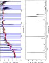 |
Fig. A.1. PKS 0023–26: Upper panel: UVB+VIS Nuclear spectrum (black solid line) and best-fit model (red solid line) for the continuum emission, regions of the spectrum corresponding to masked emission lines are indicated in blue. Lower panel: residual spectrum after subtraction of the stellar continuum showing the emission lines associated with the warm ionised gas. Wavelengths are plotted in Å, and the flux scale is given in units of 1017 erg s−1 cm−2 Å−1. We note that plots with detailed fits to the emission lines in this source are presented in the main text. |
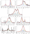 |
Fig. A.3. PKS 0252–71: First row: [O III]λλ4958,5007 Å (left panel) and Hβ line (right panel) fits. Second row: Hα + [N II]λλ6548,84 Å line fits. Third row: [S II]λλ6717,31 Å (left panel) and [S II]λλ4069,76 Å (right panel) trans-auroral line fits. The latter fit includes also the Hδ line. Fourth row: [O II]λλ7319,30 Å (left panel) and [O II]λλ3726,29 Å (right panel) trans-auroral line fits. When needed, the former fit includes also the [O II]λ7381 Å line which has been modelled with a single Gaussian component. In each of the figures the upper panel shows the best fit (red solid line) of the observed spectrum (black solid line) while the lower panel shows the residuals of the fit. The different kinematic components used for the fit of each emission line are showed with different colours and line styles, in the case of doublets where flux ratios have been fixed (i.e. the [O III]λλ4958,5007 Å and the [N II]λλ6548,84 Å), we show the total profile of each doublet kinematic component. The vertical dashed lines marks the rest-frame wavelength of the fitted emission lines. Wavelengths are plotted in Å, and the flux scale is given in units of 10−17 erg s−1 cm−2 Å−1. |
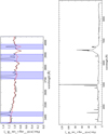 |
Fig. A.4. PKS 1151–34: Upper panel: UVB+VIS Nuclear spectrum (black solid line) and best-fit model (red solid line) for the continuum emission in the wavelength range 3350−4450 Å regions of the spectrum corresponding to masked emission lines are indicated in blue. Lower panel: nuclear spectrum (with no subtraction of the stellar continuum) showing the emission lines associated with the warm ionised gas an the BLR emission. Wavelengths are plotted in Å, and the flux scale is given in units of 1017 erg s−1 cm−2 Å−1. |
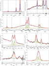 |
Fig. A.5. PKS 1151–34: First row: [O III]λλ4958,5007 Å + Hβ line fit (left panel) and a zoom-in (right panel) highlighting the presence of the emission from the AGN BLR. Second row: [O I]λλ6300,6363 Å + Hα + [N II]λλ6548,84 Å + [S II]λλ6717,31 Å line fits. Third row: [S II]λλ6717,31 Å (left panel) and [S II]λλ4069,76 Å (right panel) trans-auroral line fits. The latter fit includes also the Hδ line. Fourth row: [O II]λλ7319,30 Å (left panel) and [O II]λλ3726,29 Å (right panel) trans-auroral line fits. When needed, the former fit includes also the [O II]λ7381 Å line which has been modelled with a single Gaussian component. In each of the figures the upper panel shows the best fit (red solid line) of the observed spectrum (black solid line) while the lower panel shows the residuals of the fit. The different kinematic components used for the fit of each emission line are showed with different colours and line styles, in the case of doublets where flux ratios have been fixed (i.e. the [O III]λλ4958,5007 Å and the [N II]λλ6548,84 Å), we show the total profile of each doublet kinematic component. The vertical dashed lines marks the rest-frame wavelength of the fitted emission lines. The AGN BLR has been modelled by the components shown with grey colour whose centroid velocity is also marked by the grey vertical dashed line. Wavelengths are plotted in Å, and the flux scale is given in units of 10−17 erg s−1 cm−2 Å−1. |
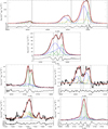 |
Fig. A.9. PKS 1549–79: First row: [O III]λλ4958,5007 Å + Hβ line fit. Second row: Hα + [N II]λλ6548,84 Å line fits. Third row: [S II]λλ6717,31 Å (left panel) and [S II]λλ4069,76 Å + Hδ (right panel) trans-auroral line fits. Fourth row: [O II]λλ7319,30 Å (left panel) and [O II]λλ3726,29 Å (right panel) trans-auroral line fits. In each of the figures the upper panel shows the best fit (red solid line) of the observed spectrum (black solid line) while the lower panel shows the residuals of the fit. The different kinematic components used for the fit of each emission line are showed with different colours and line styles, in the case of doublets where flux ratios have been fixed (i.e. the [O III]λλ4958,5007 Å and the [N II]λλ6548,84 Å), we show the total profile of each doublet kinematic component. The vertical dashed lines marks the rest-frame wavelength of the fitted emission lines. Wavelengths are plotted in Å, and the flux scale is given in units of 10−17 erg s−1 cm−2 Å−1. |
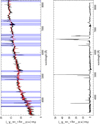 |
Fig. A.10. PKS 1814–63: as in Fig. A.1. |
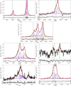 |
Fig. A.11. PKS 1814–63: as in Fig. A.3. |
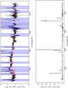 |
Fig. A.12. PKS 2135–209: as in Fig. A.1. |
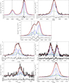 |
Fig. A.13. PKS 2135–209: as in Fig. A.3. |
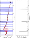 |
Fig. A.14. PKS 2314+03: as in Fig. A.1. |
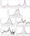 |
Fig. A.15. PKS 2314+03: as in Fig. A.9. |
Appendix B: Models
The electron density and the reddening derived using the DDD diagram presented in Fig. 5 depends on the chosen fiducial photoionisation model grids. We ran a new set of models using CLOUDY version 17.00 (Ferland et al. 2017) to test the effect that the different model parameters, and in particular the ionisation parameter U and the metallicity of the gas, have on the final results. For that, we constructed a grid of photoionisation models with CLOUDY (version 17.00 Ferland et al. 2017), covering a large range of gas and AGN properties. The details and assumptions of these models are similar to those presented and discussed by Baron & Netzer (2019b), and we briefly summarise them here. In particular, we used the “single cloud” approach, where we assumed spherical shells of gas with different densities, column densities, and distances from the central ionising source. The gas was assumed to be optically thick and geometrically thin, and we dis not model cases in which the gas is optically thin and extends over regions that are as large, or even larger, than the distance from the central source (e.g. see Baron et al. 2018). Such models require information on the gas spatial distribution, which is not available in our case.
We modelled the central ionising source using standard assumptions about the spectral energy distribution (SED) of AGN. The SED consisted of an optical-UV continuum emitted by an optically thick and geometrically thin accretion disk, with an additional X-ray power-law source that extends to 50 keV with a photon index of Γ = 1.9. We took the normalisation of the UV (2500 Å) to X-ray (2 keV) to be αOX = 1.37. We considered four different cases for the shape of the ionising SED, which correspond to sources with different AGN properties (see Table A.1 in Baron & Netzer 2019b). In particular, the SEDs we considered had different mean energies of ionising photon of 2.56, 2.65, 3.15, and 4.17 Ryd. The typical AGN in our sample is well-described by an SED with a mean energy of an ionising photon of 2.56 Ryd (SED 2 in Table A.1 in Baron & Netzer 2019b), which we take as our fiducial AGN SED. We note that using different SEDs has a negligible effect on our results and conclusions.
The grid of models consists of a geometrically thin, optically thick, shells of dusty gas, with ISM-type grains and the appropriate depletion. We assumed constant density clouds4, with hydrogen number density ranging from nH = 102 cm−3 to nH = 105 cm−3. We considered four different gas metallicities: 0.5, 1, 1.5, and 2 Z⊙. Finally, many of the ionised gas properties depend on the ionisation parameter, U = Q(Lyman)/4πr2nHc, where Q(Lyman) is the number of the hydrogen-ionising photons, r is the gas distance from the central ionising source, nH is the hydrogen number density, and c is the speed of light. We therefore considered a wide range in ionisation parameter, from log U = −3.8 to log U = −2. The distance of the gas from the central source was set according to each combination of hydrogen number density and ionisation parameter.
The resulting model grid consists of 896 models with different gas and AGN properties. For each model, we extracted the predicted auroral [O II] and trans-auroral [S II] line luminosities, and applied dust reddening with colour excess ranging from E(B − V) = 0 mag to E(B − V) = 1 mag, assuming Cardelli et al. (1989) extinction curve. Figure B.1 shows the predicted tr [O II] and [S II] line ratios as a function of the different gas and AGN properties. The colour of the markers represents the ionisation parameter of the gas, and the size of the markers represents the metallicity, where 0.5 Z⊙ corresponds to the smallest marker, while 2 Z⊙ corresponds to the largest. The shapes of the markers represent the ionising SED, where the squares, stars, circles, and triangles correspond to SEDs with a mean energy of ionising photon of 2.56, 2.65, 3.15, and 4.17 Ryd, respectively. The predicted line ratios depend primarily on the hydrogen number density and the dust reddening, both of which are indicated with arrows in the diagram. The strong dependence of the line ratios on these two parameters suggests that the line ratios can be used to estimate the density and reddening of the ionised cloud (as initially discussed by Holt et al. 2011).
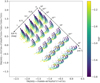 |
Fig. B.1. Predicted auroral [OII] and trans-auroral [SII] line ratios for the 896 models considered in this work. The hydrogen number density ranges from 102 cm−3 to 105 cm−3, and the reddening ranges from E(B − V) = 0 mag to E(B − V) = 1 mag, both of which are indicated with arrows in the diagram. The colour of the markers represents the ionisation parameter, where log U = −3.8 is marked with purple and log U = −2 is marked with yellow. The size of the markers represents the gas metallicity, where the smallest markers correspond to 0.5 Z⊙ and the largest correspond to 2 Z⊙. The shapes of the markers represent different shapes of the ionising SED, where squares, stars, circles, and triangles correspond to SEDs with a mean energy of ionising photon of 2.56, 2.65, 3.15, and 4.17 Ryd, respectively. See text for additional details about the models. |
Inspecting Fig. B.1, one can see that the ionisation parameter and the gas metallicity have a non-negligible effect on the predicted line ratios, and thus on the derived density and reddening of the ionised cloud. In particular, for nH ≤ 104 cm−3, different ionisation parameters can change the derived reddening by 0.1−0.2 mag, and the inferred hydrogen density by 0.2−0.7 dex. For high density clouds, nH ∼ 105 cm−3, varying the ionisation parameter has a stronger impact on the derived reddening, but less so on the derived hydrogen density. On the other hand, for lower density clouds, nH ≤ 104 cm−3, varying the gas metallicity affects the derived hydrogen density (by 0.1−0.3 dex), while for higher density clouds, it mostly effects the derived reddening (by ∼0.2 mag). We note that the shape of the ionising SED can change the tr [O II] and [S II] line ratios but its effect on the derived density and reddening is smaller compared to variations in ionisation parameter and/or gas metallicity.
As discussed in the main text, in order to estimate the gas density and reddening due to dust for a given gas component of a given target from the DDD, a fiducal model needs to be assumed. In this work we considered only the models with solar metallicity and our fiducial AGN SED and we selected as fiducal the photoionisation model with the ionisation parameter closest to the empirically derived one in Sect. 4.3. We then calculated a denser grid of models, with hydrogen density ranging from nH = 102 cm−3 to nH = 105 cm−3 with 0.1 dex jumps, and E(B − V) colour excess ranging from 0 to 1 mag with 0.05 mag jumps and use this finer grid to derive the electron density and the reddening from our observed tr[O II] and [S II] line ratios.
Appendix C: Comparison with the E(B − V) and ne measured with alternative methods
To check our DDD-derived reddening estimates and densities, we compared them with reddening values estimated via the classical Hα/Hβ Balmer decrement, and gas densities determined using the method proposed by Baron & Netzer (2019b). For the reddening estimates we used total line fluxes only, which we believe give more robust measurements. Values of E(B − V) were determined using the observed Hα/Hβ ratio using the Cardelli et al. (1989) reddening law with RV = 3.1 and a theoretical Hα/Hβ = 2.85 consistently with the way reddenings are derived from the models in the DDD. Errors were calculated by taking into account the errors on the fluxes of the emission lines. From Fig. C.1 it is clear that the Balmer decrement estimates are systematically higher for most of the sample. However, taking into account the errors, the values are consistent within 0.2 mag for all the galaxies in our sample excluding PKS 1549–79 and PKS 0252–71. It is most likely that these discrepancies can be ascribed to the degeneracies in the emission line modelling which can particularly affect the Hα + [N II] blend due to the extreme kinematics of the ionised gas in our sources, as can be observed from the figures presented in Appendix A.
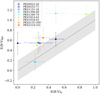 |
Fig. C.1. Comparison between the gas reddening estimated using the DDD presented in Fig. 5 (E(B − V)tr) and the Hα/Hβ Balmer decrement (E(B − V)BD). Different galaxies have different colours following the convention showed in the legend in upper left part. The dotted line marks the 1:1 relation and the shaded area a scatter of 0.2 in E(B − V). |
PKS 1549–79 and PKS 0252–71 are the two targets that show the highest discrepancy between the reddenings derived with the two methods, and we believe this might be related to the uncertainties in the stellar population fitting. In fact, the nuclear spectrum of PKS 0252–71 has a higher noise level compared to the rest of the sample, especially around the Hα line, which increases the uncertainties on the flux of this emission line due to the starlight continuum subtraction. In the case of PKS 1549–79 the difficulty in taking into account the level of the continuum is related to the fact that it noticeably increase towards the red part of the spectrum. Looking at the stellar population fit is seems possible that around the [O III] and Hβ lines our best fit is overestimating the continuum level leading us to underestimate the Hβ flux. An additional factor to consider in the case of PKS 1549–79 is that there may be an underlying BLR component to the Hα + [N II] blend that we did not include in our fit because we obtained an adequate fit using NLR components alone. However, Holt et al. (2006) did detect this BLR component, and its presence in our spectrum could potentially boost the NLR Hα flux used in our analysis of reddening.
In Fig. C.2 we compare the densities of the outflowing gas estimated using the DDD diagram and the equation
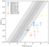 |
Fig. C.2. Comparison between the outflowing gas electron densities extracted using the DDD presented in Fig. 5 (ne tr) and the Baron & Netzer (2019b) calibration (ne Baron19). The ne Baron19 have been extracted using both the Heckman et al. (2004) (empty circles) and the Lamastra et al. (2009) (filled circles) calibrations for the LBOL. Different galaxies have different colours following the convention showed in the legend in upper left part. The dotted line marks the 1:1 relation and the shaded areas a scatter of 0.5 and 1 in log ne. The errors do not take into account the scatter of the LBOL calibration. |
taken from Baron & Netzer (2019b).
In order to estimate the densities with the latter method we made use of our estimates of the outflow radii (Sect. 4.2) and ionisation parameter (Sect. 4.3), and took the AGN bolometric luminosities derived using both the Heckman et al. (2004) and the Lamastra et al. (2009) calibrations as described in Sect. 4.5. This is the first time that a one-to-one comparison between these two methods has been performed, with the goal of setting the ground to explore the possible biases and limitations of the two methods (see also Davies et al. 2020). Figure C.2 shows that we find discrepancies higher than one order of magnitude between the densities derived in this paper using the trans-auroral lines and those derived using the Baron & Netzer (2019b) method, with the latter giving systematically higher densities for all the galaxies in our sample As discussed in Sect. 4.5, the Heckman et al. (2004) calibration gives higher LBOL compared to the Lamastra et al. (2009) calibration, thus increasing the discrepancy between the two sets of densities.
It is worth noting here that, by comparing the densities estimated with the two methods, we are actually checking if the quantities we derived in our work (mainly the outflow densities and radii, and the AGN LBOL) are compatible with the ionisation state of the gas (measured via the ionisation parameter U) that produces the observed line ratios.
We estimated U from the observed line ratios following the prescriptions of Baron & Netzer (2019b). The latter is a robust method that does not strongly depend on the details of the photoionisation models (e.g. AGN SED shape and gas metallicity). In addition, looking at both our sample and other, often larger, AGN samples (e.g. Baron & Netzer 2019a; Davies et al. 2020), the derived values of the ionisation parameter typically change by less than an order of magnitude across each sample. For this reason, we believe that the errors on U are playing a minor role, and attribute the discrepancy between the densities mainly to the uncertainties on the derived LBOL and outflow radii. The comparison between the densities is thus indicating that we are likely to be overestimating LBOL, while also underestimating the outflow radii r due to projection effects (see the discussion in Sect. 4.5).
In Sect. 4.5 we described the possible uncertainties on the estimated LBOL for our type of sources and our choice to adopt the Lamastra et al. (2009) calibration. We also considered different calibrations for the AGN bolometric luminosites, namely the Netzer (2009) calibration using the Hβ fluxes from our observations, the Runnoe et al. (2012) calibration using 24 μm IR fluxes taken from Dicken et al. (2009), and finally the bolometric luminosities reported by Mingo et al. (2014) using X-ray data, however this did not mitigate the discrepancies between the two sets of electron densities in a significant way. As discussed in Sect. 4.3 we can exclude the idea that shocks are significantly boosting the [O III] emission, leading us to overestimate the AGN bolometric luminosities. We further emphasise that the X-ray bolometric correction (XBC) adopted in the Lamastra et al. (2009) paper (taken from Marconi et al. 2004) is the main source of uncertainty on the LBOL calculated from X-ray luminosities, and can lead up to a factor of 2 uncertainty (Hopkins et al. 2007).
The uncertainties on the outflow radii and on the LBOL, taken together, make it feasible to lower the densities estimated with the Baron & Netzer (2019b) method by about one order of magnitude and thus reconcile their values with the DDD densities. As well as a lower LBOL and larger r, an alternative explanation might be that the clouds emitting the trans-auroral [S II] and [O II] lines have lower densities and are emitted on larger scales than those emitting the [O III] and Hβ lines, which are key for determining the ionisation parameter. However, we believe that this alternative explanation is unlikely for the following reasons.
It would be difficult to avoid the higher density clouds emitting substantial [S II] and [O II] trans-auroral line emission, since the latter lines have significantly higher critical densities than [O III]λ5007. One possibility is that the high density clouds are matter-bounded, such that the partially ionised zones at the backs of the clouds that would normally emit the [S II] and [O II] lines are absent. However, any matter-bounded high density clouds would need to have just the right column depth to reduce the trans-auroral line flux, but avoid decreasing the Hβ flux too much, otherwise the [O III]/Hβ ratio and ionisation parameter would be overestimated, and other line ratios such as He II(4686)/Hβ would be too high.
If the putative lower density clouds were at the same radius as the higher density clouds emitting the [OIII] and Hβ, then they would inevitably have a higher ionisation parameter and therefore be expected to emit substantial [O III] and Hβ emission. Moreover, the lower density clouds would probably be larger than the higher density ones, increasing their covering factor for the ionising continuum and boosting their [O III] and Hβ luminosity further.
To avoid the lower density clouds emitting substantial [O III] and Hβ emission, they must be situated at much larger radial distances from the nucleus. For example, for them to have the same ionisation parameter as the high density clouds emitting the [O III] and Hβ lines, they would need to be ∼3× further away; and to achieve an ionisation parameter that is, say, 10× lower (to avoid significant [O III] emission) for the low density clouds than for the high density clouds, they would need to be 10× further away (several kpc for some sources). We would already be able to detect such large radial extents for the trans-auroral lines in our spectra, but we do not.
The trans-auroral lines are broad and show disturbed kinematics (even if not measured as well as for [OIII] due to blending issues). It seems unlikely that this would be the case if the clouds were situated at large radii. In this context, it is notable that, for the one case in which we have been able to measure precise densities for the narrow, intermediate and broad components separately using the DDD technique – PKS 1934–63 – it is the broadest kinematic components that have the highest trans-auroral densities (Santoro et al. 2018).
All Tables
Main properties of the radio sources in our sample, namely their radio ID (Col. 1), infrared ID (Col. 2), radio classification (Col. 3), redshift (Col. 4), angular-to-linear conversion factor (Col. 5), luminosity at 5 GHz (Col. 6), position angle (Col. 7), and linear diameter (Col. 8).
Radio sources in the sample and their galactic E(B − V) values (Col. 2) taken from the NASA/IPAC infrared science archive, and stellar absorption-line redshifts (Col. 3) derived from our stellar continuum fit.
Velocity shifts (v) and FWHM (in km s−1) of the [O III] reference model kinematic components (indicated with a progressive number from 1 to 4 from lower to higher FWHM).
Kinematic parameters for the outflows: flux weighted velocity (Col. 2) and FWHM (Col. 3), and maximum outflow velocity (Col. 4).
Radii of the warm ionised gas outflows as estimated from the optical data (HST or X-shooter) (Col. 2) and the radio source radii taken from the literature (Col. 3).
Spectral windows used to extract spatial profiles of the stellar continuum light (Cols. 2 and 3) and of the outflowing gas (Col. 4) from the X-shooter slit spectra.
Ionisation parameters for the total (Col. 2) and outflowing gas (Col. 3) emission, as determined using the method discussed in Baron & Netzer (2019b).
Logarithmic values of the [O III]/Hβ, [N II]6583/Hα, and [S II]6716+6731/Hα line ratios of the total (Cols. 2, 4, and 6) and outflowing gas (Cols. 3, 5, and 7) emission for the sources in our sample.
Trans-auroral [O II] and [S II] ratios, together with the derived density ne and E(B − V) values for the total (Cols. 2–5) and the outflowing (Col. 6–9) gas emission, as determined from the DDD using total line fluxes and broad-component line fluxes, respectively.
Total [O III]5007 Å line fluxes (Col. 2), the [O III] observed (Col. 3) and dust corrected (Col. 4) luminosities, and the AGN bolometric luminosities calculated following the Lamastra et al. (2009) (Col. 5) and the Heckman et al. (2004) (Col. 6) calibrations.
Hβ flux (Col.2), the observed and intrinsic Hβ luminosity of the total (Cols. 3–4) and the outflowing gas (Cols. 5–7).
Masses of the gas emitting the total (MT) and outflow (Mout) emission in units of solar mass, and the fraction of the masses associated with the outflowing gas expressed as a percentage of the total gas mass.
Mass outflow rates Ṁ, the outflow kinetic powers Ė, and the AGN feedback efficiencies F for the targets of our sample, as estimated by following the classical (Cols. 2–4) and the vmax (Cols. 5–7) approaches.
Total (T) and outflowing (out) gas flux of the [O II]λλ3726,29 Å (Col. 2), [O II]λλ7319,30 Å (Col. 3), [S II]λλ4069,76 Å (Col. 4), and [S II]λλ6717,31 Å (Col. 5) trans-auroral lines.
Hα and the [N II]λλ6548,84 Å total and outflowing gas line fluxes (Cols. 2–3 and Cols. 4–5, respectively).
All Figures
|
Fig. 1. HST ACS/WFC images of PKS 0023–26 (top) and PKS 1306–09 (bottom). Left-hand panels: narrow-band [O III] images, right-hand panels: intermediate-band continuum images. In each case, the dashed line shows the direction of the radio axis. We note that in both cases, the brightest extended [O III] structures are closely aligned in angle with the radio axes (within ∼10°). |
| In the text | |
|
Fig. 2. Emission-line profiles for PKS 0023–26: First row: [O III]λλ4958,5007 Å (left panel) and Hβ line (right panel) fits. Second row: Hα + [N II]λλ6548,84 Å line fits. Third row: [S II]λλ6717,31 Å (left panel) and [S II]λλ4069,76 Å (right panel) trans-auroral line fits. The latter fit includes also the Hδ line. Fourth row: [O II]λλ7319,30 Å (left panel) and [O II]λλ3726,29 Å (right panel) trans-auroral line fits. The former fit also includes the [O II]λ7381 Å line which has been modelled with a single Gaussian component. In each of the sub-figures the upper panel shows the best fit (red solid line) of the observed spectrum (black solid line) while the lower panel shows the residuals of the fit. The different kinematic components used for the fit of each emission line are showed with different colours and line styles. In the case of doublets where flux ratios have been fixed (i.e. the [O III]λλ4958,5007 Å and the [N II]λλ6548,84 Å) we show the total profile of each doublet kinematic component. The vertical dashed lines marks the rest-frame wavelength of the fitted emission lines. Wavelengths are plotted in Å, and the flux scale is given in units of 10−17 erg s−1 cm−2 Å−1. |
| In the text | |
|
Fig. 3. Position-velocity diagrams obtained by applying the spectro-astrometry technique to the [O III]λ5007 Å line in the slit spectra of PKS 0252–71 and PKS 2135–209. The diagrams show the position of the fitted centroids of the [O III]λ5007 Å emission line spatial profiles, expressed as offsets in parsecs from the host galaxy centre, as a function of velocity measured with respect to the [O III]λ5007 Å rest-frame velocity. The black dotted vertical and horizontal lines mark the zero point of the two axes. The blue dashed lines mark the error weighted mean position of the [O III] spatial profiles offsets at v < 500 km s−1 and at v > 500 km s−1 (shown in blue), while the red dashed line marks their average. |
| In the text | |
|
Fig. 4. Locations of our targets in the [O III]/Hβ vs [N II]6583/Hα and [O III]/Hβ vs [S II]6716,31/Hα BPT diagrams. Filled circles mark the line ratios obtained from total line fluxes while empty circles are related to the line emission of the broad components only. The solid line in both panels is the Kewley et al. (2001) maximum starburst line. The dashed line in the left panel is the semi-empirical Kauffmann et al. (2003) line and has bee used together with the Kewley et al. (2001) line to separate between line ratios due to photoionisation from stars (HII), AGN or a mixture of both (Comp). The dashed line in the right panel is the Kewley et al. (2006) line separating the AGN between Seyferts and LINERS. |
| In the text | |
|
Fig. 5. Location of our targets in the density diagnostic diagram (DDD) using the logarithm of the tr[O II] = [O II](3727+3729)/(7318+7319+7330+7331) and of the tr[S II] = [S II](4068+4076)/(6716+6731) line ratios. Error bars have been estimated by propagating the line flux errors while upper/lower limits have been assigned as described in the text; different sources in our sample are marked with different colours as indicated by the legend in the upper right corner of the left panel. For comparison, the DDD also includes the results obtained for the ULIRGs studied by Spence et al. (2018) and Rose et al. (2018) (thin light grey points), two of which also host a compact radio source (thin black points). AGN photoionisation grid models for gas with solar metallicity and two ionisation parameters – log U = −2.5 (light grey colour) and log U = −3.5 (black colour) – are shown with dotted lines. The model grids have been created by fixing the gas metallicity and ionisation parameter while varying the electron density in the interval ne = 100 − 105 cm−3 (from top left to bottom right) and the reddening in the interval E(B − V) = 0 − 1 mag (from top right to bottom left). Left panel: DDD showing the line ratios based on the total line fluxes. Right panel: DDD showing the outflows line ratios determined from the integrated fluxes of broad components of the emission lines. For each galaxy in our sample a solid line connects the line ratios of the total (as shown in the left panel) and outflowing gas emission. |
| In the text | |
|
Fig. 6. AGN bolometric luminosity as a function of the outflow velocity, vout for our sample (back filled points) and the comparison samples (see legend in the upper left). To distinguish them from the rest of the comparison sample, the markers of the two ULIRGs hosting a compact radio source have a black edge colour. The black dashed line marks a |
| In the text | |
|
Fig. 7. Mass outflow rate (left panel) and kinetic power of the outflow (right panel) as a function of the AGN bolometric luminosity for our sample (black points) and the comparison samples (see legend in the upper left of the left panel). To distinguish them from the rest of the comparison sample, the markers of the two ULIRGs hosting a compact radio source have a black edge colour. To enable a fair comparison with the ionised gas outflows of Fiore et al. (2017) we also assumed an outflow gas density of ne = 200 cm−3 for all our targets (black empty circles). The CO outflow detected in PKS 1549–79 by Oosterloo et al. (2019) has been also included in this plot using our estimate of the source LBOL, a green dashed vertical line connects the warm ionised and the molecular outflow Ṁ and Ė values for this object to highlight the differences between the outflows properties in the two gas phases. The dotted and dashed black lines in the left panel represent the best fit relations found by Fiore et al. (2017) for the molecular gas and ionised gas outflows, respectively. The dotted, dashed and solid black lines in the right panel mark the correlations Ė = 1, 0.1, 0.01 LBOL. |
| In the text | |
|
Fig. A.1. PKS 0023–26: Upper panel: UVB+VIS Nuclear spectrum (black solid line) and best-fit model (red solid line) for the continuum emission, regions of the spectrum corresponding to masked emission lines are indicated in blue. Lower panel: residual spectrum after subtraction of the stellar continuum showing the emission lines associated with the warm ionised gas. Wavelengths are plotted in Å, and the flux scale is given in units of 1017 erg s−1 cm−2 Å−1. We note that plots with detailed fits to the emission lines in this source are presented in the main text. |
| In the text | |
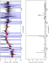 |
Fig. A.2. PKS 0252–71: as in Fig. A.1. |
| In the text | |
|
Fig. A.3. PKS 0252–71: First row: [O III]λλ4958,5007 Å (left panel) and Hβ line (right panel) fits. Second row: Hα + [N II]λλ6548,84 Å line fits. Third row: [S II]λλ6717,31 Å (left panel) and [S II]λλ4069,76 Å (right panel) trans-auroral line fits. The latter fit includes also the Hδ line. Fourth row: [O II]λλ7319,30 Å (left panel) and [O II]λλ3726,29 Å (right panel) trans-auroral line fits. When needed, the former fit includes also the [O II]λ7381 Å line which has been modelled with a single Gaussian component. In each of the figures the upper panel shows the best fit (red solid line) of the observed spectrum (black solid line) while the lower panel shows the residuals of the fit. The different kinematic components used for the fit of each emission line are showed with different colours and line styles, in the case of doublets where flux ratios have been fixed (i.e. the [O III]λλ4958,5007 Å and the [N II]λλ6548,84 Å), we show the total profile of each doublet kinematic component. The vertical dashed lines marks the rest-frame wavelength of the fitted emission lines. Wavelengths are plotted in Å, and the flux scale is given in units of 10−17 erg s−1 cm−2 Å−1. |
| In the text | |
|
Fig. A.4. PKS 1151–34: Upper panel: UVB+VIS Nuclear spectrum (black solid line) and best-fit model (red solid line) for the continuum emission in the wavelength range 3350−4450 Å regions of the spectrum corresponding to masked emission lines are indicated in blue. Lower panel: nuclear spectrum (with no subtraction of the stellar continuum) showing the emission lines associated with the warm ionised gas an the BLR emission. Wavelengths are plotted in Å, and the flux scale is given in units of 1017 erg s−1 cm−2 Å−1. |
| In the text | |
|
Fig. A.5. PKS 1151–34: First row: [O III]λλ4958,5007 Å + Hβ line fit (left panel) and a zoom-in (right panel) highlighting the presence of the emission from the AGN BLR. Second row: [O I]λλ6300,6363 Å + Hα + [N II]λλ6548,84 Å + [S II]λλ6717,31 Å line fits. Third row: [S II]λλ6717,31 Å (left panel) and [S II]λλ4069,76 Å (right panel) trans-auroral line fits. The latter fit includes also the Hδ line. Fourth row: [O II]λλ7319,30 Å (left panel) and [O II]λλ3726,29 Å (right panel) trans-auroral line fits. When needed, the former fit includes also the [O II]λ7381 Å line which has been modelled with a single Gaussian component. In each of the figures the upper panel shows the best fit (red solid line) of the observed spectrum (black solid line) while the lower panel shows the residuals of the fit. The different kinematic components used for the fit of each emission line are showed with different colours and line styles, in the case of doublets where flux ratios have been fixed (i.e. the [O III]λλ4958,5007 Å and the [N II]λλ6548,84 Å), we show the total profile of each doublet kinematic component. The vertical dashed lines marks the rest-frame wavelength of the fitted emission lines. The AGN BLR has been modelled by the components shown with grey colour whose centroid velocity is also marked by the grey vertical dashed line. Wavelengths are plotted in Å, and the flux scale is given in units of 10−17 erg s−1 cm−2 Å−1. |
| In the text | |
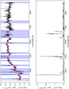 |
Fig. A.6. PKS 1306–09: as in Fig. A.1. |
| In the text | |
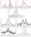 |
Fig. A.7. PKS 1306–09: as in Fig. A.3. |
| In the text | |
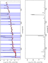 |
Fig. A.8. PKS 1549–79: as in Fig. A.1. |
| In the text | |
|
Fig. A.9. PKS 1549–79: First row: [O III]λλ4958,5007 Å + Hβ line fit. Second row: Hα + [N II]λλ6548,84 Å line fits. Third row: [S II]λλ6717,31 Å (left panel) and [S II]λλ4069,76 Å + Hδ (right panel) trans-auroral line fits. Fourth row: [O II]λλ7319,30 Å (left panel) and [O II]λλ3726,29 Å (right panel) trans-auroral line fits. In each of the figures the upper panel shows the best fit (red solid line) of the observed spectrum (black solid line) while the lower panel shows the residuals of the fit. The different kinematic components used for the fit of each emission line are showed with different colours and line styles, in the case of doublets where flux ratios have been fixed (i.e. the [O III]λλ4958,5007 Å and the [N II]λλ6548,84 Å), we show the total profile of each doublet kinematic component. The vertical dashed lines marks the rest-frame wavelength of the fitted emission lines. Wavelengths are plotted in Å, and the flux scale is given in units of 10−17 erg s−1 cm−2 Å−1. |
| In the text | |
|
Fig. A.10. PKS 1814–63: as in Fig. A.1. |
| In the text | |
|
Fig. A.11. PKS 1814–63: as in Fig. A.3. |
| In the text | |
|
Fig. A.12. PKS 2135–209: as in Fig. A.1. |
| In the text | |
|
Fig. A.13. PKS 2135–209: as in Fig. A.3. |
| In the text | |
|
Fig. A.14. PKS 2314+03: as in Fig. A.1. |
| In the text | |
|
Fig. A.15. PKS 2314+03: as in Fig. A.9. |
| In the text | |
|
Fig. B.1. Predicted auroral [OII] and trans-auroral [SII] line ratios for the 896 models considered in this work. The hydrogen number density ranges from 102 cm−3 to 105 cm−3, and the reddening ranges from E(B − V) = 0 mag to E(B − V) = 1 mag, both of which are indicated with arrows in the diagram. The colour of the markers represents the ionisation parameter, where log U = −3.8 is marked with purple and log U = −2 is marked with yellow. The size of the markers represents the gas metallicity, where the smallest markers correspond to 0.5 Z⊙ and the largest correspond to 2 Z⊙. The shapes of the markers represent different shapes of the ionising SED, where squares, stars, circles, and triangles correspond to SEDs with a mean energy of ionising photon of 2.56, 2.65, 3.15, and 4.17 Ryd, respectively. See text for additional details about the models. |
| In the text | |
|
Fig. C.1. Comparison between the gas reddening estimated using the DDD presented in Fig. 5 (E(B − V)tr) and the Hα/Hβ Balmer decrement (E(B − V)BD). Different galaxies have different colours following the convention showed in the legend in upper left part. The dotted line marks the 1:1 relation and the shaded area a scatter of 0.2 in E(B − V). |
| In the text | |
|
Fig. C.2. Comparison between the outflowing gas electron densities extracted using the DDD presented in Fig. 5 (ne tr) and the Baron & Netzer (2019b) calibration (ne Baron19). The ne Baron19 have been extracted using both the Heckman et al. (2004) (empty circles) and the Lamastra et al. (2009) (filled circles) calibrations for the LBOL. Different galaxies have different colours following the convention showed in the legend in upper left part. The dotted line marks the 1:1 relation and the shaded areas a scatter of 0.5 and 1 in log ne. The errors do not take into account the scatter of the LBOL calibration. |
| In the text | |
Current usage metrics show cumulative count of Article Views (full-text article views including HTML views, PDF and ePub downloads, according to the available data) and Abstracts Views on Vision4Press platform.
Data correspond to usage on the plateform after 2015. The current usage metrics is available 48-96 hours after online publication and is updated daily on week days.
Initial download of the metrics may take a while.