| Issue |
A&A
Volume 595, November 2016
|
|
|---|---|---|
| Article Number | A30 | |
| Number of page(s) | 17 | |
| Section | Cosmology (including clusters of galaxies) | |
| DOI | https://doi.org/10.1051/0004-6361/201628629 | |
| Published online | 25 October 2016 | |
Combining strong lensing and dynamics in galaxy clusters: integrating MAMPOSSt within LENSTOOL
I. Application on SL2S J02140-0535⋆,⋆⋆
1 Instituto de Astronomía, Universidad Nacional Autónoma de México, Apdo. postal 106, CP 22800, Ensenada, B.C Mexico
e-mail: This email address is being protected from spambots. You need JavaScript enabled to view it.
2 Instituto de Física y Astronomía, Universidad de Valparaíso, Avenida Gran Bretaña 1111, Valparaíso, Chile
3 Laboratoire d’Astrophysique de Marseille, Université de Provence, CNRS, 38 rue Frédéric Joliot-Curie, 13388 Marseille Cedex 13, France
4 Institut d’Astrophysique de Paris (UMR 7095: CNRS & UPMC), 98bis Bd Arago, 75014 Paris, France
5 Max-Planck Institute for Extraterrestrial Physics, Giessenbachstrasse, 85748 Garching, Germany
6 INAF−IASF Milano, via E. Bassini 15, 20133 Milano, Italy
7 INAF−Osservatorio Astronomico di Trieste, via G. B. Tiepolo 11, 34143 Trieste, Italy
8 Instituto de Astrofísica, Facultad de Física, Pontificia Universidad Católica de Chile, Av. Vicuña Mackenna 4860, 7820436 Macul, Santiago, Chile
9 Laboratoire d’Astrophysique de Toulouse-Tarbes, Université de Toulouse, CNRS, 57 avenue d’Azereix, 65 000 Tarbes, France
10 Institut Utinam, CNRS UMR 6213, Université de Franche-Comté, OSU THETA Franche-Comté-Bourgogne, Observatoire de Besançon, BP 1615, 25010 Besançon Cedex, France
11 Facultad de Ciencias Físico-Matemáticas, Universidad Autónoma de Nuevo León, San Nicolás de los Garza, Mexico
12 Department of Physics and Astronomy, University of California, Riverside, CA 92521, USA
Received: 2 April 2016
Accepted: 11 August 2016
Abstract
Context. The mass distribution in galaxy clusters and groups is an important cosmological probe. It has become clear in recent years that mass profiles are best recovered when combining complementary probes of the gravitational potential. Strong lensing (SL) is very accurate in the inner regions, but other probes are required to constrain the mass distribution in the outer regions, such as weak lensing or studies of dynamics.
Aims. We constrain the mass distribution of a cluster showing gravitational arcs by combining a strong lensing method with a dynamical method using the velocities of its 24 member galaxies.
Methods. We present a new framework in which we simultaneously fit SL and dynamical data. The SL analysis is based on the LENSTOOL software and the dynamical analysis uses the MAMPOSSt code, which we integrated into LENSTOOL. After describing the implementation of this new tool, we applied it to the galaxy group SL2S J02140-0535 (zspec = 0.44), which we had previously studied. We used new VLT/FORS2 spectroscopy of multiple images and group members, as well as shallow X-ray data from XMM.
Results. We confirm that the observed lensing features in SL2S J02140-0535 belong to different background sources. One of these sources is located at zspec = 1.017 ± 0.001, whereas the other source is located at zspec = 1.628 ± 0.001. With the analysis of our new and our previously reported spectroscopic data, we find 24 secure members for SL2S J02140-0535. Both data sets are well reproduced by a single NFW mass profile; the dark matter halo coincides with the peak of the light distribution, with scale radius, concentration, and mass equal to rs = 82+44-17 kpc, c200 = 10.0+1.7-2.5, and M200 = 1.0+0.5-0.2 × 10¹⁴ M⊙ respectively. These parameters are better constrained when we fit SL and dynamical information simultaneously. The mass contours of our best model agrees with the direction defined by the luminosity contours and the X-ray emission of SL2S J02140-0535. The simultaneous fit lowers the error in the mass estimate by 0.34 dex, when compared to the SL model, and in 0.15 dex when compared to the dynamical method.
Conclusions. The combination of SL and dynamics tools yields a more accurate probe of the mass profile of SL2S J02140-0535 up to r200. However, there is tension between the best elliptical SL model and the best spherical dynamical model. The similarities in shape and alignment of the centroids of the total mass, light, and intracluster gas distributions add to the picture of a non-disturbed system.
Key words: gravitational lensing: strong / galaxies: groups: general / galaxies: groups: individual: SL2S J02140-0535
SL2S: Strong Lensing Legacy Survey.
Based on observations obtained with MegaPrime/MegaCam, a joint project of CFHT and CEA/IRFU, at the Canada-France-Hawaii Telescope (CFHT) which is operated by the National Research Council (NRC) of Canada, the Institut National des Science de l’Univers of the Centre National de la Recherche Scientifique (CNRS) of France, and the University of Hawaii. This work is based in part on data products produced at Terapix available at the Canadian Astronomy Data Centre as part of the Canada-France-Hawaii Telescope Legacy Survey, a collaborative project of NRC and CNRS. Also based on Hubble Space Telescope (HST) data, VLT (FORS 2) data, and XMM data.
© ESO, 2016
1. Introduction
The Universe has evolved into the filamentary and clumpy structures (dubbed the cosmic web, Bond et al. 1996) that are observed in large redshift surveys (e.g., Colless et al. 2001). Massive and rich galaxy clusters are located at the nodes of this cosmic web, which are fed by accretion of individual galaxies and groups (e.g., Frenk et al. 1996; Springel et al. 2005; Jauzac et al. 2012). Galaxy clusters are the most massive gravitationally bound systems in the Universe, thus constituting one of the most important and crucial astrophysical objects to constrain cosmological parameters (see for example Allen et al. 2011). Furthermore, they provide information about galaxy evolution (e.g., Postman et al. 2005). Also, galaxy groups are important cosmological probes (e.g., Mulchaey 2000; Eke et al. 2004b) because they are tracers of the large-scale structure of the Universe, but also because they are probes of the environmental dependence of the galaxy properties, galactic content of dark matter haloes, and clustering of galaxies (Eke et al. 2004a). Although there is no clear boundary in mass between groups of galaxies and clusters of galaxies (e.g., Tully 2015), it is commonly assumed that groups of galaxies lie in the intermediate mass range between large elliptical galaxies and galaxy clusters (i.e., masses between ~1013 M⊙ to ~1014 M⊙).
The mass distribution in both galaxy groups and clusters has been studied extensively using different methods, such as the radial distribution of the gas through X-ray emission (e.g., Sun 2012; Ettori et al. 2013, and references therein), the analysis of galaxy-based techniques that employs the positions, velocities, and colors of the galaxies (see Old et al. 2014, 2015, for a comparison of the accuracies of dynamical methods in measuring M200), or through gravitational lensing (e.g., Limousin et al. 2009, 2010; Kneib & Natarajan 2011, and references therein). Each probe has its own limitations and biases, which in turn impact the mass distribution measurements. Strong lensing (hereafter SL) analysis provides the total amount of mass and its distribution with no assumptions on either the dynamical state or the nature of the matter producing the lensing effect. Nevertheless, the analysis has its own weakness; for example, it can solely constrain the two-dimensional projected mass density and it is limited to small projected radii. On the other hand, the analysis of galaxy kinematics does not have such limitations, but assumes local dynamical equilibrium (i.e., negligible rotation and streamings motions) and spherical symmetry.
In this paper, we put forward a new method to overcome one of the limitations of the SL analysis, namely, the impossibility of constraining large-scale properties of the mass profile. Our method combines SL (in a parametric fashion, see Sect. 2) with the dynamics of the group or the cluster galaxy members, fitting both data sets simultaneously. Strong lensing and dynamics are both well-recognized probes, the former providing an estimate of the projected two-dimensional mass distribution within the core (typically a few dozens of arcsecs at most), whereas the latter is able to study the density profile at larger radii, using galaxies as test particles to probe the host potential.
There are several methods to constrain the mass profiles of galaxy clusters from galaxy kinematics. One can fit the second and fourth moments of the line-of-sight (hereafter LOS) velocities in bins of projected radii (Łokas & Mamon 2003). One can assume a profile for the velocity anisotropy and apply mass inversion techniques (e.g., Mamon & Boué 2010; Wolf et al. 2010; Sarli et al. 2014). Both methods require binning of the data. An alternative is to fit the observed distribution of galaxies in projected phase space (projected radii and LOS velocity, hereafter PPS), which does not involve binning the data. This can be performed by assuming six-dimensional distribution functions (DFs), expressed as function of energy and angular momentum (e.g., Wojtak et al. 2009; who used DFs derived by Wojtak et al. 2008, for ΛCDM halos), but the method is very slow, as it involves triple integrals for every galaxy and every point in parameter space. An accurate and efficient alternative is to assume a shape of the velocity DF, as in the method called Modelling Anisotropy and Mass Profiles of Observed Spherical Systems (MAMPOSSt) of Mamon et al. (2013), which has been used to study the radial profiles of mass and velocity anisotropy of clusters (Biviano et al. 2013, 2016; Munari et al. 2014; Guennou et al. 2014). For the aims of the present study, MAMPOSSt is ideal as it 1) is accurate for and very rapid a dynamical model, a valuable asset, since lensing modeling has become time demanding, see, for example the discussion in Jauzac et al. (2014) about the computing resources when modeling a SL cluster with many constraints; 2) produces a likelihood, as does the LENSTOOL1 code used here for SL (see Sect. 2); and 3) can run with the same parametric form of the mass profile as used in LENSTOOL.
The idea of combining lensing and dynamics is not new. So far, dynamics have been used to probe the very center of the gravitational potential, through the measurement of the velocity dispersion profile of the central brightest cluster galaxy (Sand et al. 2002, 2004; Newman et al. 2009, 2013). However, the use of dynamical information at large scale (velocities of the galaxy members in a cluster or a group), together with SL analysis has not been fully explored. Through this approach, Thanjavur et al. (2010) showed that it is possible to characterize the mass distribution and the mass-to-light ratio of galaxy groups. Biviano et al. (2013) analyzed the cluster MACS J1206.2-0847, constraining its mass, velocity-anisotropy, and pseudo-phase-space density profiles, finding a good agreement between the results obtained from cluster kinematics and those derived from lensing. Similarly, Guennou et al. (2014) compared the mass profile inferred from lensing with different profiles obtained from three methods based on kinematics, showing that they are consistent among themselves.
This work follows the analysis of Verdugo et al. (2011), hereafter VMM11, where we combined SL and dynamics in the galaxy group SL2S J02140-0535. In VMM11, dynamics were used to constrain the scale radius of a NFW mass profile, which is a quantity that is not accessible to SL constraints alone. These constraints were used as a prior in the SL analysis, allowing VMM11 to probe the mass distribution from the center to the virial radius of the galaxy group. However, the fit was not simultaneous. In this work we propose a framework aimed at fitting SL and dynamics simultaneously, combining the likelihoods obtained from both techniques in a consistent way. Our paper is arranged as follows: in Sect. 2 the methodology is explained. In Sects. 3 and 4 we present the observational data images, spectroscopy, and the application of the method to the galaxy group SL2S J02140-0535. We summarize and discuss our results in Sect. 5. Finally in Sect. 6, we present the conclusions. All our results are scaled to a flat, ΛCDM cosmology with ΩM = 0.3,ΩΛ = 0.7 and a Hubble constant H0 = 70 km s-1 Mpc-1. All images are aligned with WCS coordinates, i.e., north is up, east is left. Magnitudes are given in the AB system.
2. Methodology
In this section we explain how the SL and dynamical likelihoods are computed in our models.
2.1. Strong lensing
The figure-of-merit function, χ2, which quantifies the goodness of the fit for each trial of the lens model, has been introduced in several works (e.g., Verdugo et al. 2007; Limousin et al. 2007; Jullo et al. 2007), therefore, we summarize the method here. Consider a model whose parameters are θ, with N sources, and ni the number of multiple images for source i. We compute, for every system i, the position in the image plane xj(θ) of image j, using the lens equation. Therefore, the contribution to the overall χ2 from multiple image system i is ![Mathematical equation: \begin{equation} \label{eq:Chi2Lens} \chi_{i}^{2} = \sum_{j\,=\,1}^{n_i} \frac{\left[x_{\rm obs}^j - x^j(\theta) \right]^2}{\sigma_{ij}^{2}}, \end{equation}](/articles/aa/full_html/2016/11/aa28629-16/aa28629-16-eq26.png) (1)
(1)
where σij is the error on the position of image j, and  is the observed position. Thus, we can write the likelihood as
 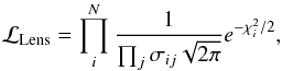 (2)where it is assumed that the noise associated with the measurement of each image position is Gaussian and uncorrelated (Jullo et al. 2007). This is not true in the case of images that are very close to each other, but it is a reasonable approximation for SL2S J02140-0535. In this work we assume that the error in the image position is σij = 0.5″, which is slightly greater than the value adopted in VMM11, but is half the value that has been suggested by other authors in order to take into account systematic errors in lensing modeling (e.g., Jullo et al. 2010; D’Aloisio & Natarajan 2011; Host 2012; Zitrin et al. 2015).
2.2. Dynamics
The MAMPOSSt (Mamon et al. 2013) method performs a maximum likelihood fit of the distribution of observed tracers in PPS. Mamon et al. (2013) provide a detailed description and we present a summary of this method. The MAMPOSSt method assumes parameterized radial profiles of mass and velocity anisotropy and a shape for the three-dimensional velocity distribution (a Gaussian 3D velocity distribution); MAMPOSSt fits the distribution of observed tracers in PPS. The method has been tested in cosmological simulations, showing the possibility to recover the virial radius, tracer scale radius, and dark matter scale radius when using 100 to 500 tracers (Mamon et al. 2013). Moreover, Old et al. (2015) found that the mass normalization M200 is recovered with 0.3 dex accuracy for as few as ~30 tracers.
The velocity anisotropy is defined through the expression 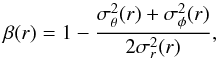 (3)
(3)
where, in spherical symmetry, σφ(r) = σθ(r). We adopt a constant anisotropy model with σr/σθ = (1 −β)−1/2, assuming spherical symmetry (see Sect. 4).
The 3D velocity distribution is assumed to be Gaussian, ![Mathematical equation: \begin{equation} \label{eq:3Ddis} f_{\upsilon} = \frac{1}{(2\pi)^{3/2}\sigma_{r}\sigma^2_{\theta}}\exp\left[- \frac{\upsilon^2_{r}}{2\sigma^2_{r}} - \frac{\upsilon^2_{\theta} + \upsilon^2_{\phi} }{2\sigma^2_{\theta}} \right], \end{equation}](/articles/aa/full_html/2016/11/aa28629-16/aa28629-16-eq38.png) (4)where υr, υθ, and υφ are the velocities in a spherical coordinate system. This Gaussian distribution assumes no rotation or radial streaming, which is a good assumption inside the virial radius, as has been shown by numerical simulations (Prada et al. 2006; Cuesta et al. 2008). The Gaussian 3D velocity model is a first-order approximation, which can be improved (see Beraldo e Silva et al. 2015).
(4)where υr, υθ, and υφ are the velocities in a spherical coordinate system. This Gaussian distribution assumes no rotation or radial streaming, which is a good assumption inside the virial radius, as has been shown by numerical simulations (Prada et al. 2006; Cuesta et al. 2008). The Gaussian 3D velocity model is a first-order approximation, which can be improved (see Beraldo e Silva et al. 2015).
Thereby, MAMPOSSt fits the parameters using maximum likelihood estimation, i.e., by minimizing 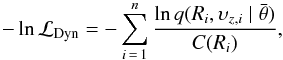 (5)where q is the probability density of observing an object at projected radius R with LOS velocity υz, for a N-parameter vector
  . And C(Ri) is the completeness of the data set (see Sect. 3.2).
2.3. Combining likelihoods
In order to combine SL and dynamical constraints, we compute their respective likelihoods. The SL likelihood is computed via LENSTOOL code. This software implements a Bayesian Monte Carlo Markov chain (MCMC) method to search for the most likely parameters in the modeling. This code has been used in a large number of clusters studies and characterized in Jullo et al. (2007). The likelihood coming from dynamics of cluster members is computed using the MAMPOSSt code (Mamon et al. 2013), which has been tested and characterized on simulations. Technically, we incorporated the MAMPOSSt likelihood routine into LENSTOOL.
The SL likelihood (see Eq. (2)) depends on the image positions of the arcs and their respective errors. On the other hand, the MAMPOSSt likelihood is calculated through the projected radii and LOS velocity (Eq. (5)). The errors on the inputs for the strong lensing, on one hand, and MAMPOSSt, on the other, should not be correlated; in other words, the joint lensing-dynamics covariance matrix should be diagonal. So, we can write  (6)where ℒDyn is given by Eq. (5) and ℒLens is calculated through Eq. (2). This definition of a total likelihood, where the two techniques (lensing and dynamics) are considered independent, is not new, and has been used previously at different scales by other authors (e.g., Sand et al. 2002, 2004); we are using the dynamics to obtain constraints in the outer regions. In this sense, the main difference from previous works, as for example Biviano et al. (2013), Guennou et al. (2014), or VMM11, is that in this work we do a joint analysis, searching for a solution that is consistent with both methods that maximizes a total likelihood. Additionally, we assume the same weight of the SL and dynamics on the total likelihood, however, this cannot be the case, for example, when combining SL and weak lensing (see the discussion in Umetsu et al. 2015).
2.4. NFW mass profile
We adopt the NFW mass density profile that has been predicted in cosmological N-body simulations (Navarro et al. 1996, 1997), given by  (7)
(7)
where rs is the radius that corresponds to the region where the logarithmic slope of the density equals the isothermal value, and ρs is a characteristic density. The scale radius is related to the virial radius r200 through the expression c200 = r200/rs, which is the so-called concentration. Where the radius r200 is the radius of a spherical volume inside of which the mean density is 200 times the critical density at the given redshift z,  . The mass contained within a radius r of the NFW halo is given by
 ![Mathematical equation: \begin{equation} \label{eq:mass} M(r) = 4\pi r_{\rm s}^{3}\rho_{\rm s} \left[\ln{(1+r/r_{\rm s}}) - \frac{r/r_{\rm s}}{1+r/r_{\rm s}}\right]\cdot \end{equation}](/articles/aa/full_html/2016/11/aa28629-16/aa28629-16-eq59.png) (8)Although other mass models (e.g., Hernquist or Burkert density profiles) have been studied within the MAMPOSSt formalism (see Mamon et al. 2013), and LENSTOOL allows to probe different profiles, we adopt the NFW profile to compare our results with those obtained in VMM11. The NFW profile is a spherical density profile and the MAMPOSSt formalism can only model spherical systems. The initial profile is spherical with LENSTOOL, however, but is transformed into a pseudo-elliptical NFW (see Golse & Kneib 2002), as is explained in Jullo et al. (2007), to perform the lensing calculations. Although the simultaneous modeling shares the same spherical parameters, the difference between the pseudo-elliptical and the spherical framework could influence our methodology (see Sect. 4.3).
(8)Although other mass models (e.g., Hernquist or Burkert density profiles) have been studied within the MAMPOSSt formalism (see Mamon et al. 2013), and LENSTOOL allows to probe different profiles, we adopt the NFW profile to compare our results with those obtained in VMM11. The NFW profile is a spherical density profile and the MAMPOSSt formalism can only model spherical systems. The initial profile is spherical with LENSTOOL, however, but is transformed into a pseudo-elliptical NFW (see Golse & Kneib 2002), as is explained in Jullo et al. (2007), to perform the lensing calculations. Although the simultaneous modeling shares the same spherical parameters, the difference between the pseudo-elliptical and the spherical framework could influence our methodology (see Sect. 4.3).
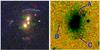 |
Fig. 1 Images of the group SL2S J02140-0535 at zspec = 0.44. Left: composite HST/ACS F814, F606, and F475 color image (22″ × 22″ = 125 × 125 kpc2) showing the central region of the group (from VMM11). Right: composite WIRCam J,Ks color image (22″ × 22″). |
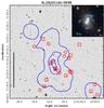 |
Fig. 2 CFHTLS i-band image with the luminosity density contours for SL2S J02140-0535. They represent 1 × 10⁶, 5 × 10⁶, and 1.0 × 10⁷L⊙kpc-2 from outermost to innermost contour, respectively. The red squares and circles show the location of the 24 confirmed members of the group, the squares represent the galaxies previously reported by Muñoz et al. (2013), and the circles represent the new observations. The black vertical line on the left represents 1 Mpc at the group rest frame. The inset in the top-right corner shows a 30″× 30″ CFHTLS false color image of the system. |
3. Data
In this section, we present the group SL2S J02140-0535, briefly reviewing our old data sets. Also, we present new data that we have obtained since VMM11. From space, the lens was followed up with the X-ray Multi-Mirror Mission (XMM-Newton Space Telescope). Additionally, a new spectroscopic follow up of the arcs and group members were carried out with the Very Large Telescope (VLT).
3.1. SL2S J02140-0535
This group, located at zspec = 0.44, is populated by three central galaxies. We label them as G1 (the brightest group galaxy, BGG), G2, and G3 (see left panel of Fig. 1). The lensed images consist of three arcs surrounding these three galaxies: arc A, situated north of the deflector, composed by two merging images; a second arc in the east direction (arc B), which is associated with arc A, whereas a third arc, arc C, situated in the south, is singly imaged. SL2S J02140-0535 (first reported by Cabanac et al. 2007) was studied previously using strong lensing by Alard (2009) and both strong and weak lensing by Limousin et al. (2009), and also kinematically by Muñoz et al. (2013).
SL2S J02140-0535 was observed in five filters (u∗, g′, r′, i′, z′) as part of the CFHTLS (Canada-France-Hawaii Telescope Legacy Survey)2 using the wide-field imager MegaPrime (Gwyn 2011), and in the infrared using WIRCam (Wide-field InfraRed Camera, the near-infrared mosaic imager at CFHT) as part of the proposal 07BF15 (P.I. G. Soucail); see Verdugo et al. (2014) for more information. In the right panel of Fig. 1 we show a false-color image of SL2S J02140-0535, combining the two bands J and Ks. Arcs A and C appear mixed with the diffuse light of the central galaxies, and arc B is barely visible in the image. SL2S J02140-0535 was also followed up spectroscopically using FORS 2 at VLT (VMM11).
From space, the lens was observed with the Hubble Space Telescope (HST) in snapshot mode (C 15, P.I. Kneib) using three bands, with the ACS camera (F814, F606, and F475).
3.2. New spectroscopic data
Selecting members. We used FORS 2 on VLT with a medium resolution grism (GRIS 600RI; 080.A-0610; PI V. Motta) to target the group members (see Muñoz et al. 2013) and a low resolution grism (GIRS 300I; 086.A-0412; P.I. V. Motta) to observe the strongly lensed features. In the later observation, we use one mask with 2 × 1300 s on-target exposure time. Targets (other than strongly lensed features) were selected via a two-step process. First, we use the T0005 release of the CFHTLS survey (November, 2008) to obtain a photometric redshift-selected catalog, which includes galaxies within ± 0.01 of the redshift of the main lens galaxy. The galaxies in this catalog have colors within (g−i)lens−0.15 <g−i< (g−i)lens + 0.15, where (g−i)lens is the color of the brightest galaxy within the Einstein radius. From this sample, we selected those candidates that were not observed previously. More details will be presented in a forthcoming publication (Motta et al., in prep.).
The spectroscopic redshifts of the galaxies were determined using the Radial Velocity SAO package (Kurtz & Mink 1998) within the IRAF software3. By visual inspection of the spectra, we identify several emission and absorption lines. Then, we determine the redshifts (typical errors are discussed in Muñoz et al. 2013) via cross-correlation between a spectrum and the template spectra of known velocities. To determine the group membership of SL2S J02140-0535, we follow the method presented in Muñoz et al. (2013), which in turn adopted the formalism of Wilman et al. (2005). The group members are identified as follows: we assume initially that the group is located at the redshift of the main bright lens galaxy, zlens, with an initial observed-frame velocity dispersion of σobs = 500(1+zlens) km s-1. After computing the required redshift range for group membership (see Muñoz et al. 2013) and applying a biweight estimator (Beers et al. 1990), the iterative process reached a stable membership solution with 24 secure members and a velocity dispersion of σ = 562 ± 60 km s-1. These galaxies are shown with red squares and circles in Fig. 2, and their respective redshifts are presented in Table A.1. The squares in Fig. 2 represent the galaxies previously reported by Muñoz et al. (2013). Figure 2 also shows the luminosity contours, which are calculated according to Foëx et al. (2013). Fitting ellipses to the luminosity map, using the task ellipse in IRAF, we find that the luminosity contours have position angles equal to 99° ± 9°, 102° ± 2°, and 109° ± 2°, from outermost to innermost contour respectively.
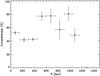 |
Fig. 3 Completeness as a function of the radius in SL2S J02140-0535. C ~ 60% roughly constant up to 1 Mpc. |
Completeness. Muñoz et al. (2013) presented the dynamical analysis of seven SL2S galaxy groups, including SL2S J02140-0535. They estimated the completeness within 1 Mpc of radius from the center of the group to be 30%. In the present work, as we increased the number of observed galaxies in the field of SL2S J02140-0535, and thus increasing the number of confirmed members (hereafter galspec), a new calculation is carried out to estimate the completeness as a function of the radius. We first define the color-magnitude cuts to be applied to the photometric catalog of the group, i.e., 0.7 < (r−i) < 0.92 and 21.44 <mi< 21.47. These values correspond to the photometric properties of the galspec. We exclude one galaxy because of its color, (r−i) = 0.45. Then, we select all the galaxies falling within the photometric ranges (hereafter galphot), and we estimate the density of field galaxies within the 15′ × 15′ square arcminutes after excluding a central region of radius 1.3 Mpc, which is the largest distance from the center of the group of galspec. This density is then converted into an estimated total number of galaxies Nfield over the full field of view.
Given galspec, we bin the data and define Nspec(ri) as the number of confirmed members in the ith radial bin. Thus, the radial profile of the completeness is given by  (9)where Nfield,r(ri) is the number of field galaxies in the ith bin, and Nt(ri) is the total number of galphot present in the ith bin, i.e., its value is the sum of the number of group members and field galaxies. To estimate Nfield,r(ri), a Monte Carlo approach is adopted. We randomly draw the positions of the Nfield galaxies over the whole field of view, and then count the corresponding number of galaxies Nfield,r(ri) falling in each bin. Thus, each Monte Carlo realization leads to an estimate of the completeness. Finally, we average the C(ri), after excluding the realizations for which we obtain Nt(ri) <Nr(ri) or C(ri) > 1. In Fig. 3 we present the resulting profile and its estimated 1σ deviation, showing a completeness C ~ 60% that is consistent with a constant profile up to 1 Mpc.
3.3. Multiple images: confirming two different sources
Spectroscopic redshifts. In VMM11 we reported a strong emission line at 7538.4 Å in the spectra of arc C, that we associated with [OII]λ3727 at zspec = 1.023 ± 0.001. We obtained new 2D spectra for the arcs consisting in two exposures of 1300 s each. Because of the closeness of the components (inside a radius of ~8′′), the slit length is limited by the relative position of the arcs, making sky-subtraction difficult (see bottom panel of Fig. 4). Most of the 2D spectra show a poor sky subtraction compared to that which we would have obtained using longer slits. However, our new 2D spectra also show the presence of [OII]λ3727 spectral feature and additionally another emission line appears in the spectrum, [OIII]λ4958.9. In the same Fig. 4 (top right panel) we show the spectrum and indicated some characteristic emission lines, along with a few sky lines. We compare the spectrum with a template of a starburst galaxy from Kinney et al. (1996), shifted at z = 1.02. After performing a template fitting using RVSAO, we obtain zspec = 1.017 ± 0.001, confirming our previously reported value.
On the other hand, in our previous work, we did not found any spectroscopic features in the arcs A and B owing to the poor signal to noise. In the top left panel of Fig. 4 we show the new obtained spectrum of arc A. It reveals a weak (but still visible) emission line at 9795.3 Å. This line probably corresponds to [OII]λ3727 at z ~ 1.6. We do not claim a clear detection, as this region of the spectrum is affected by sky emission lines (as we discuss above), but it is worth noting that the photometric redshift estimate supports this detection (see Fig. 5). Assuming emission from [OII]λ3727 and applying a Gaussian fitting, we obtain zspec = 1.628 ± 0.001. This feature is not present in the spectrum of arc B, since arc B is almost one magnitude fainter than arc A. Furthermore, this line is not present in the spectrum of arc C, which confirms the previous finding of VMM11, i.e., system AB and arc C come from two different sources.
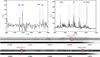 |
Fig. 4 Top panel: as mentioned in Sect. 3.3, the slit length was limited by the position of the arcs, hence producing poor sky subtraction. Left: observed spectrum of arc A (black continuous line). In gray we depict a starburst template from Kinney et al. (1996) shifted at z = 1.628, and we indicate a possible [OII]λ3727 emission line, and some sky lines, in blue (see Sect. 3.3). Right: observed spectrum of arc C (black continuous line), as before we depicted in gray the starburst template from Kinney et al. (1996), but shifted at z = 1.02. We indicated some characteristic emission lines, along with the sky lines in blue, but we omit for clarity the labels of the last lines. Bottom panel: two-dimensional spectra of arc A (with a color bar in arbitrary units). We note the [OII]λ3727 emission line. Below, we show the two-dimensional spectra of arc C, with two emission lines clearly identified: [OII]λ3727, and [OIII]λ4958.9. |
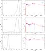 |
Fig. 5 Left column: photometric redshift PDF for the selected arcs (see text). The dashed vertical lines correspond to the spectroscopic value. Right column: best-fit spectral energy distribution. Points represent the observed CFHTLS broadband magnitudes, and J and Ks from WIRCam. Vertical and horizontal error bars correspond to photometric error and wavelength range of each filter, respectively. |
Photometric redshifts. As a complementary test, and to extend the analysis presented in VMM11, we calculate the photometric redshifts of arcs A, B, and C using the HyperZ software (Bolzonella et al. 2000), adding the J and Ks-bands to the original bands (u∗, g′, r′, i′, z′). The photometry in J and Ks-bands was performed with the IRAF package apphot. We employed polygonal apertures to obtain a more accurate flux measurement of the arcs. For each arc, the vertices of the polygons were determined using the IRAF task polymark, and the magnitudes inside these apertures were computed by the IRAF task polyphot. The results are presented in Table A.2.
It is evident in the right panel of Fig. 1 that the gravitational arcs are contaminated by the light of the central galaxies. To quantify the error in our photometric measurements, in the J and Ks-bands we proceed as follows. We subtract the central galaxies of the group and follow the procedure described in McLeod et al. (1998), that is, we fit a galaxy profile model convolved with a point spread function (PSF); de Vaucouleurs profiles were fitted to the galaxies with synthetic PSFs. After the subtraction, we run the IRAF task polyphot again. The errors associated with the fluxes are defined as the quadratic sum of the errors on both measurements.
The photometric redshifts for the arcs were estimated from the magnitudes reported in Table A.2, and those reported in VMM11. We present the output probability distribution function (PDF) from HyperZ in Fig. 5. We note in the same figure that the Ks-band data do not match with the best-fit spectral energy distribution; this is probably related to the fact that the photometry of the arcs is contaminated by the light of the central galaxies. Arc C is constrained to be at zphot = 0.96 ± 0.07, which is in good agreement with the zspec = 1.017 ± 0.001 reported above. The multiple imaged system constituted by arcs A and B have zphot = 1.7 ± 0.1 and zphot = 1.6 ± 0.2, respectively. The photometric redshift of arc A is in agreement with the identification of the emission line as [OII]λ3727 at zspec = 1.628 ± 0.001.
To summarize, the spectroscopic and photometric data both confirm the results of VMM11, namely, the system formed by arcs A and B, and the single arc C, originate from two different sources, the former at zspec = 1.628 and the latter at zspec = 1.017.
3.4. X-ray data
We observed SL2S J02140-0535 with XMM as part of an X-ray follow-up program of the SL2S groups to obtain an X-ray detection of these strong-lensing selected systems and to measure the X-ray luminosity and temperature (Gastaldello et al., in prep.). SL2S J02140-0535 was observed by XMM for 19 ks with the MOS detector and for 13 ks with the pn detector. The data were reduced with SAS v14.0.0, using the tasks emchain and epchain. We considered only event patterns 0−12 for MOS and 0−4 for pn, and the data were cleaned using the standard procedures for bright pixels, hot columns removal, and pn out-of-time correction. Periods of high backgrounds due to soft protons were filtered out leaving an effective exposure time of 11 ks for MOS and 8 ks for pn.
For each detector, we create images with point sources in the 0.5−2 keV band. The point sources were detected with the task edetect_chain, and masked using circular regions of 25′′ radius centered at the source position. The images were exposure corrected and background subtracted using the XMM-Extended Source Analysis Software (ESAS). The XMM image in the 0.5−2 keV band of the field of SL2S J02140-0535 is shown in Fig. 6.
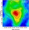 |
Fig. 6 Adaptively smoothed image of SL2S J02140-0535 in the 0.5−2.0 keV band. The X-ray contours in black are linearly spaced from 5 to 20 cts/s/deg2. |
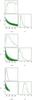 |
Fig. 7 PDFs and contours of the parameters c200 and rs. The three contours stand for the 68%, 95%, and 99% confidence levels. The values obtained for our best-fit model are indicated with a gray square and with vertical lines in the 1D histograms; the asymmetric errors are presented in Table 1. Top panel: results from the SL model. Middle panel: results from the Dyn model. Bottom panel: results from the SL+Dyn model. |
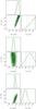 |
Fig. 8 PDFs and contours of the parameters logrs and logr200. The three contours stand for the 68%, 95%, and 99% confidence levels. The values obtained for our best-fit model are indicated with a gray square and with vertical lines in the 1D histograms; the asymmetric errors are presented in Table 1. Top panel: results from the SL model. Middle panel: results from the Dyn model.Bottom panel: results from the SL+Dyn model. |
The X-ray peak is spatially coincident with the bright galaxies inside the arcs, and the X-ray isophotes are elongated in the same direction as the optical contours (see discussion in Sect. 5). The quality of the X-ray snapshot data is not sufficient for a detailed mass analysis assuming hydrostatic equilibrium (e.g., Gastaldello et al. 2007). In this case, the mass can only be obtained adopting a scaling relation, such as a mass-temperature relation (e.g., Gastaldello et al. 2014). Therefore this mass determination is not of the same quality as that obtained with our lensing and dynamical information. In addition, as we discuss in Sect. 5, we need to be very cautious when assuming scaling relations for strong lensing clusters. We only make use of the morphological information provided by the X-ray data hereinafter.
 |
Fig. 9 PDFs and contours of the parameters c200 and M200. The three contours stand for the 68%, 95%, and 99% confidence levels. The values obtained for our best-fit model are shown with a gray square and with vertical lines in the 1D histograms; the asymmetric errors are presented in Table 1. Top panel: results from the SL model. Middle panel: results from the Dyn model. Bottom panel: results from the SL+Dyn model. |
4. Results
In this Section, we apply the formalism outlined in Sect. 2 on SL2S J02140-0535, using the data presented in Sect. 3. In the subsequent analysis, SL model refers to the SL modeling, Dyn model to the dynamical analysis, and SL+Dyn model to the combination of both methods.
4.1. SL model
As we discussed in VMM11, the system AB shows multiple subcomponents (surface brightness peaks) that can be conjugated as different multiple image systems, increasing the number of constraints as well as the degrees of freedom (for a fixed number of free parameters). Thus, the AB system is transformed into four different systems, conserving C as a single-image arc (see Fig. 4 in VMM11). In this way, our model has five different arc systems in the optimization procedure, leading to 16 observational constraints. Based on the geometry of the multiple images, the absence of structure in velocity space, and the X-ray data, we model SL2S J02140-0535 using a single large-scale mass clump accounting for the dark matter component. This smooth component is modeled with a NFW mass density profile, characterized by its position, projected ellipticity, position angle, scale radius, and concentration parameter. The position, (X,Y) ranges from –5″ and 5″, the ellipticity from 0 < ϵ < 0.7, and the position angle from 0 to 180 deg. The parameters rs and c200 are free to range between 50 kpc ≤rs≤ 500 kpc, and 1 ≤c200≤ 30, respectively.
Additionally, we add three smaller-scale clumps that are associated with the galaxies at the center of SL2S J02140-0535. We model them as follows: as in VMM11, we assume that the stellar mass distribution in these galaxies follows a pseudo-isothermal elliptical mass distribution (PIEMD). A clump modeled with this profile is characterized by the following seven parameters: the center position, (X,Y), the ellipticity ϵ, the position angle θ, and the parameters, σ0, rcore, and rcut (see Limousin et al. 2005; Elíasdóttir et al. 2007, for a detailed discussion of the properties of this mass profile). The center of the profiles, ellipticity, and position angle are assumed to be the same as for the luminous components. The remaining parameters in the small-scale clumps, namely, σ0, rcore, and rcut, are scaled as a function of their galaxy luminosities (Limousin et al. 2007), using as a scaling factor the luminosity L∗ associated with the g-band magnitude of galaxy G1 (see Fig. 1),
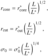 (10)setting
  and
and  to be 0.15 kpc and 253 km s-1, respectively. This velocity dispersion is obtained from the LOS velocity dispersion of galaxy G1, with the use of the relation reported by Elíasdóttir et al. (2007). This LOS velocity dispersion has a value of
  km s-1, which is computed from the G-band absorption line profile (see VMM11). The last parameter,
  , is constrained from the possible stellar masses for galaxy G1 (VMM11), which in turn produce an interval of 1−6 kpc.
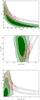 |
Fig. 10 Joint distributions. Top panel: scale radius and concentration. Middle panel: log rs and log r200. Bottom panel: concentration and M200. Green-filled contours are 1, 2, and 3σ regions from the Dyn model. Gray contours stand for the 68, 95, and 99% confidence levels for the SL model. Red contours is the result of the SL+Dyn model with the best solution depicted with a red star. |
Our model is computed and optimized in the image plane with the seven free parameters discussed above, namely {X, Y, ϵ, θ, rs, c200, }. The first six parameters characterize the NFW profile, and the last parameter is related to the profile of the central galaxies. All the parameters are allowed to vary with uniform priors. We show the results (the PDF) of the SL analysis only in top panel of Fig. 7, and the best-fit parameters are given in Table 1. Additionally, in Fig. 8 we show the plots of rs vs. r200, since these plots provide us with a better understanding of how unconstrained is the lens model at large scale (see next section), and also to be consistent with the form in which the plots are presented in Mamon et al. (2013). Figure 9 shows the results for the concentration and M200, from which we can gain insight for the mass constraint.
4.2. Dyn model
Since we only have 24 group members, we assume that the group has an isotropic velocity dispersion (i.e., β = 0 in Eq. (3)). This parameter β might influence the parameters of the density profile (rs and c200), however, it is not possible to constrain β with only 24 galaxies. Besides, it is beyond the scope of this work to analyze its effect over the parameters. We defer this analysis to a forthcoming paper, in which we apply the method to a galaxy cluster with a greater number of members.
The Jeans equation of dynamical equilibrium, as implemented in MAMPOSSt, is only valid for values of r ≲ 2rvir ≃ 2.7r200 (Falco et al. 2013). Thus, before running MAMPOSt, we estimate the virial radius, r200, of SL2S J02140-0535. From the scale radius and the concentration values reported in VMM11 we find the virial radius to be r200 = 1 ± 0.2 Mpc. This value is considerably smaller than the previously reported value of 1.42 Mpc by Lieu et al. (2016)4. Table A.1 shows that there are 3 galaxies with 1 Mpc <R< 1.4 Mpc, i.e., within 1.4r200, which seems sufficiently small to keep in our analysis. The galaxy members lie between 7.9 kpc to 1392.3 kpc with a mean distance of 650 kpc from the center. Given the scarce number of members in SL2S J02140-0535 we keep this galaxy in our calculations.
To further simplify our analysis, we assume that the completeness, as a function of the radius, is a constant (see Sect. 3.2). Also, we assume that both the tracer scale radius (rν in Mamon et al. 2013) and the dark matter scale radius rs are the same, that is, the total mass density profile is forced to be proportional to the galaxy number density profile: we assume that mass follows light. As we see in the next section, this is not a bad assumption. Therefore our model only has two free parameters, namely, the scale radius, rs, and the concentration, c200. These parameters have broad priors with 50 kpc ≤rs ≤ 500 kpc and 1 ≤ c200 ≤ 30. The middle panels of Figs. 7−9 show the PDF for this model; the best values of the fit are presented in Table 1.
Best-fit model parameters.
4.3. SL+Dyn model
The main difference of our work, when compared to previous works (e.g., Biviano et al. 2013; Guennou et al. 2014) is that we apply a joint analysis, seeking a solution that is consistent with both the SL and the dynamical methods, maximizing the total likelihood. In the bottom panels of Figs. 7−9, we show the PDF of this combined model. The best-fit values are presented in Table 1.
From the figures it is clear that tension exists between the results from the SL model and the Dyn model; the models are in disagreement at 1σ level. The discrepancy is related to the oversimplified assumption of the spherical Dyn model. Although in some cases it is expected to recover a spherical mass distribution at large scale (e.g., Gavazzi 2005), at smaller scale, i.e., at strong lensing scales, the mass distribution tends to be aspherical. In order to investigate such tension between the results, we construct a strong lensing spherical model with the same constrains as before. We show the results in the left panel of Fig. B.1. It is clear that in this case the model is not well constrained, a natural result given the lensing images in SL2S J02140-0535. However, the comparison between the joint distributions in the top panel of Fig. 10 and the one in the right panel of Fig. B.1 shows that the change in the contours is small, which indicates that the assumption of spherical symmetry has little impact on the final result (the agreement between contours is related to the shallow distribution from LENSTOOL, which produces a joint distribution that follows the top edge of the narrower MAMPOSSt distribution). Also, the combined model has a bimodal distribution (see right panel of Fig. B.1), with higher values of concentration inherited from the lensing constraints.
A possible way to shed more light on the systematics errors of our method is to test it with simulations. For example, we can compare spherical and non spherical halos or quantify the bias when a given mass distribution is assumed and the underlaying mass distribution is different. Such an analysis is out of the scope of the present work, however, it could be performed in the near future since the state-of-the-art simulations on lensing galaxy clusters have reached an incredible quality (e.g., Meneghetti et al. 2016).
5. Discusion
5.1. Lensing and dynamics as complementary probes
From Figs. 7 and 8, it is clear that SL model is not able to constrain the NFW mass profile. This result is expected since SL constraints are available in the very central part of SL2S J02140-0535, whereas the scale radius is generally several times the SL region. The degeneracy between c200 and rs (or rs and r200), which is related to the mathematical definition of the gravitational potential, was previously discussed in VMM11. This degeneracy commonly occurs in lensing modeling (e.g., Jullo et al. 2007). From the SL model we obtain the following values: rs =  kpc and c200 =
  . Thus, the model is not well constrained (similarly, we obtain a value of logr200 = 3.04
 kpc for the virial radius). Moreover, the mass M200 is not constrained in the SL model (see Fig. 9).
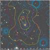 |
Fig. 11 Distribution of mass, gas, and galaxies in SL2S J02140-0535, as reflected by the total mass derived from the combined lensing and dynamics analysis (magenta), the adaptively smoothed i-band luminosity of group galaxies (yellow), and the surface brightness from XMM observations (blue). The lensing mass contours (magenta lines) correspond to projected surface densities of 0.2 × 10⁹, 1.2 × 10⁹, and 7.4 × 10⁹ M⊙ arcsec-2. The size of the image is 1.5 × 1.5 Mpc. |
The same conclusion holds when considering dynamics only, i.e., in the Dyn model the constraints are so broad that both parameters (rs and c) can be considered as unconstrained (see middle panel of Fig. 7 and middle panel of Fig. 8). In this case we obtained a scale radius of rs =  kpc, and a concentration of c200 =
  . However, in this case the scale radius is slightly more constrained when compared to the value obtained with the SL model. This is due to employing the distribution of the galaxies to estimate the value when using MAMPOSSt. Furthermore, the virial radius r200 is even more constrained with logr200 = 2.80
 kpc. These weak constraints are related to the small number of galaxy members (24) in the group. Nonetheless, even with the low number of galaxies, the error in our mass M200 (see Table 1 and Fig. 9) is approximately a factor of two, i.e., ~0.3 dex, which is consistent with the analysis of Old et al. (2015).
Interestingly, when combining both probes into the SL+Dyn model, it is possible to constrain both the scale radius and the concentration parameter. The SL model is sensitive to the mass distribution at inner radii (within 10″), whereas the dynamics provide constraints at larger radius (see bottom panels of Figs. 7 and 8). For this model, we find the values  kpc,
kpc,  , and
, and 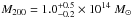 . The errors in the mass, although large, are smaller when compared to the two previous models, by a factor of 2.2 (0.34 dex) and by a factor of 1.4 (0.15 dex), for the SL model and Dyn model, respectively.
To highlight how the combined SL+Dyn model is better constrained than both the SL model and the Dyn model, we show in Fig. 10 the 2D contours for c200−rs, logrs−log r200, and c200−M200, for the three models discussed in this work. We note the overlap of the solutions of the SL model and the Dyn model, and the stronger constraints of the SL+Dyn model. The shift in the solutions for the SL+Dyn model shown in Fig. 7, i.e., rs is much lower (greater c200) than the values for the SL model and Dyn model, can be understood in light of the discussion presented in Sect. 4.3, and additionally explained with the analysis of Fig. 10. On the one hand, the tension between both results (lack of agreement between solutions at 1σ) is the result of assuming a spherical mass distribution in the Dyn model. On the other hand, the joint solution of SL+Dyn model (red contours) is consistent with the region where both the SL model and the Dyn model overlap.
5.2. Mass, light, and gas
We find that the center of the mass distribution coincides with that of the light (see Fig. 11). In VMM11 we showed that the position angle of the halo was consistent with the orientation of the luminosity contours and the spatial distribution of the group-galaxy members. In the present work we confirm these results. The measured position angles of the luminosity contours presented in Figs. 2 and 11 (the values are equal to 109°± 2°, 102° ± 2°, and 99°± 9°, from innermost to outermost contour), agree with the orientation of the position angle of  deg of the halo.
In addition to the distribution of mass and light, Fig. 11 shows the distribution of the gas component of SL2S J02140-0535, which was obtained from our X-ray analysis. The agreement between these independent observational tracers of the three group constituents (dark matter, gas, and galaxies) is remarkable. This supports a scenario in which the mass is traced by light and argues in favor of a non-disturbed structure, i.e., the opposite from a disturbed structure, where the different tracers are separated, such as in the Bullet Group (Gastaldello et al. 2014) or as in the more extreme cluster mergers (e.g., Bradač et al. 2008; Randall et al. 2008; Menanteau et al. 2012).
5.3. Comparison with our previous work
In VMM11 we analyzed SL2S J02140-0535 using the dynamical information to constrain and build a reliable SL model for this galaxy group. However, it is not expected to have a perfect agreement between the best value of the parameters computed in the former work and the values reported in the present paper, mainly because of the difference in methodologies, and the new spectroscopic number of members reported in this work. For example, in VMM11 we found the values c200 = 6.0 ± 0.6, and rs = 170 ± 18 kpc, whereas for our SL+Dyn model, we find the values c200 =  , and
, and  kpc. However, the latter values lie within the range predicted by VMM11 with dynamics (cf. 2 < c200< 8, and 50 kpc < rs< 200 kpc). Furthermore, those ranges need to be corrected using the new velocity dispersion. This correction shifts the confidence interval to higher values in c200, and lower values in rs, thus improving the agreement between both works.
Additionally, as presented in Sect. 3, we found the velocity dispersion to be σ = 562 ± 60 km s-1 with the 24 confirmed members. This velocity dispersion is in good agreement with the velocity reported in VMM11, σ = 630 ± 107 km s-1, which was computed with only 16 members, and it is also in agreement with the value obtained from weak lensing analysis ( km s-1, Foëx et al. 2013). Besides, the projected virial radius,
  Mpc (the projected harmonic mean radius, e.g., Irgens et al. 2002), is also consistent with the value reported in our previous work,
  Mpc, which was used in VMM11 to estimate the priors in the SL modeling.
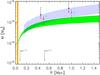 |
Fig. 12 Two-dimensional projected mass as a function of the radius measured from the BGG. The green and blue shaded areas corresponds to the mass profile within 1σ errors for the SL+Dyn model and the weak lensing model reported in VMM11, respectively. The orange-shaded region shows the area where the arc systems lie. The two red triangles with error bars show two estimates (at 0.5 and 1 Mpc) of the weak lensing mass from Foëx et al. (2013). Black diamonds (shifted in r-0.05 for clarity) show the predicted mass calculated from the work of Lieu et al. (2016). Cyan diamonds (shifted in r+0.05 for clarity) are the masses calculated from Lieu et al. (2016) data, but assuming c200 = 10 (see text). We also depict with two arrows, our best rs (for c200 = 10), and the rs (for c200 = 2.7) reported in Lieu et al. (2016). |
5.4. An over concentrated galaxy group?
The concentration value of SL2S J02140-0535 is clearly higher than the expected from ΛCDM numerical simulations. Assuming a dark matter halo at z = 0.44 with M200 ≈ 1 × 10¹⁴M⊙, the concentration is c200 ≈ 4.0 (computed with the procedures of Duffy et al. 2008). SL2S J02140-0535 was also studied by Foëx et al. (2014), who were able to constrain the scale radius and concentration parameters of galaxy groups using stacking techniques. SL2S J02140-0535, with an Einstein radius of ~7″, belongs to their stack “R3”, which was characterized to have c200 ~ 10 and M200 ~ 1014M⊙. Those values are in agreement with our computed values. As discussed thoroughly in Foëx et al. (2014), this high concentration seems to be due to an alignment of the major axis with the LOS. Even in the case in which a cluster displays mass contours elongated in the plane of the sky, the major axis could be near the LOS (see for example Limousin et al. 2007, 2013).
Finally, Fig. 12 shows the comparison between the mass obtained from our SL+Dyn model with the weak lensing mass previously obtained by VMM11. Both models overlap up to ~1 Mpc; this is consistent with the scarce number of galaxies located at radii larger than 1 Mpc. Therefore, the dynamic constraints are not strong, also the weak lensing mass estimate can be slightly overestimated at large radii, since the mass is calculated assuming a singular isothermal sphere. The red triangles in Fig. 12 show two estimates (at 0.5 and 1 Mpc) of the weak lensing mass, which are calculated using the values reported in Foëx et al. (2013). Those values are also consistent with the above-mentioned measurements. For comparison, we show the predicted mass (at 0.5 and 1 Mpc) derived from Lieu et al. (2016) in black diamonds. The discrepancy between these values and our values calculated from lensing arises from the fact that Lieu et al. (2016) set the cluster concentration from a mass-concentration relation derived from N-body simulations, thus obtaining the values c200 = 2.7 and rs = 0.52 Mpc. To prove this assertion, we performed a simple test. We used the values of M200 and c200 from Lieu et al. (2016), and then we generated a shear profile with their same radial range and number of bins. We fitted their data seeking the best M200 value, assuming a concentration value of c200 = 10. The projected mass from this estimate is shown as cyan symbols in Fig. 12. This change in concentration not only solves the difference in mass estimates, but also explains why SL2S J02140-0535 (XLSSC 110) is an outlier in the sample of Lieu et al. (2016). This highlights the risk of assuming a c−M relation for some particular objects, such as strong lensing clusters. The discussion of the bias and the effect on the M–T scaling relation will be discussed in a forthcoming publication (Foëx et al., in prep.).
6. Conclusions
We have presented a framework that allows us to simultaneously fit SL and dynamics. We apply our method to probe the gravitational potential of the lens galaxy group SL2S J02140-0535 on a large radial range, by combining two well-known codes, namely MAMPOSSt (Mamon et al. 2013) and LENSTOOL (Jullo et al. 2007). We performed a fit adopting a NFW profile and three galaxy-scale mass components as perturbations to the group potential, as previously carried out by VMM11, but we include the dynamical information in a new consistent way. The number of galaxies increased to 24, when new VLT (FORS2) spectra were analyzed. This new information was included to perform the combined strong lensing and dynamics analysis. Moreover, we studied the gas distribution within the group from X-ray data obtained with XMM.
We list our results below:
-
1.
Our new observational data set confirms the results presentedpreviously in VMM11. We also present supporting X-rayanalysis.
-
Our spectroscopic analysis confirms that the arcs AB and the arc C of SL2S J02140-0535 belong to different sources, the former at zspec = 1.017 ± 0.001 and the latter at zspec = 1.628 ± 0.001. These redshift values are consistent with the photometric redshift estimation.
-
We find 24 secure members of SL2S J02140-0535 from the analysis of our new and previously reported spectroscopic data. The completeness C ~ 60% is roughly constant up to 1 Mpc. We also computed the velocity dispersion, obtaining σ = 562 ± 60 km s-1, which is a value that is comparable to the previous estimate of VMM11.
-
The X-ray contours show an elongated shape that is consistent with the spatial distribution of the confirmed members. This argues in favor of an unimodal structure since the X-ray emission is unimodal and centered on the lens.
-
-
2.
Our method simultaneously fits strong lensing and dynamics, allowing us to probe the mass distribution from the center of the group up to its virial radius. However, there is a tension between the results of the Dyn model and the SL model, which is related to the assumed spherical symmetry of the former. While our result shows that deviation from spherical symmetry can in some cases induce a bias in the MAMPOSSt solution for the cluster M(r), this does not need to be the rule. In another massive cluster at z = 0.44, Biviano et al. (2013) found good agreement between the spherical MAMPOSSt solution and the non spherical solution from strong lensing. In addition, MAMPOSSt has been shown to provide unbiased results for the mass profiles of cluster-sized halos extracted from cosmological simulations (Mamon et al. 2013).
-
Models relying solely on either lensing(SL model) or dynamical information(Dyn model) are not able to constrain thescale radius of the NFW profile. We obtain a scale radius of
 kpc for the best SL model, whereas we obtain a value of
  kpc for the best Dyn model. We find that the concentration parameter is unconstrained as well.
 -
However, it is possible to constrain both the scale radius and the concentration parameter when combining both lensing and dynamics analysis (as previously discussed in VMM11). We find a scale radius of
kpc, and a concentration value of . The SL+Dyn model reduces the error in the mass estimation in 0.34 dex (a factor of 2.2), when compared to the SL model, and in 0.15 dex (a factor of 1.4), compared to the Dyn model. -
Our joint SL+Dyn model allows us to probe, in a reliable fashion, the mass profile of the group SL2S J02140-0535 at large scale. We find a good agreement between the luminosity contours, mass contours, and X-ray emission. This result confirms that the mass is traced by light.
-
The joint lensing-dynamical analysis presented in this paper, applied to the lens galaxy group SL2S J02140-0535, aims to show a consistent method to probe the mass density profile of groups and clusters of galaxies. This is the first paper in a series in which we extend our methodology to the galaxy clusters, for which the number of constraints is larger both in lensing images and in galaxy members. Therefore, we should be able to probe more parameters, such as the anisotropy parameter and the tracer radius (Verdugo et al., in prep.), with our new method.
The LENSTOOL software is publicly available at https://projets.lam.fr/projects/lenstool/wiki
IRAF is distributed by the National Optical Astronomy Observatory, which is operated by the Association of Universities for Research in Astronomy (AURA) under cooperative agreement with the National Science Foundation.
SL2S J02140-0535 is identified as XLSSC 110 in the XXL Survey.
Acknowledgments
The authors thank the anonymous referee for invaluable remarks and suggestions. T.V. thanks the staff of the Instituto de Física y Astronomía of the Universidad de Valparaíso. M.L. acknowledges the Centre National de la Recherche Scientifique (CNRS) for its support. V. Motta gratefully acknowledges support from FONDECYT through grant 1120741, ECOS-CONICYT through grant C12U02, and Centro de Astrofísica de Valparaíso. M.L. and E.J. also acknowledge support from ECOS-CONICYT C12U02. A.B. acknowledges partial financial support from the PRIN INAF 2014: “Glittering kaleidoscopes in the sky: the multifaced nature and role of galaxy clusters” P.I.: M. Nonino. K. Rojas acknowledges support from doctoral scholarship FIB-UV/2015 and ECOS-CONICYT C12 U02. J.M. acknowledges support from FONDECYT through grant 3160674. J.G.F-T is currently supported by Centre National d’Études Spatiales (CNES) through Ph.D. grant 0101973 and the Région de Franche-Comté and by the French Programme National de Cosmologie et Galaxies (PNCG). M. A. De Leo would like to thank the NASA-funded FIELDS program, in partnership with JPL on a MUREP project, for their support.
References
- Alard, C. 2009, A&A, 506, 609 [NASA ADS] [CrossRef] [EDP Sciences] [Google Scholar]
- Allen, S. W., Evrard, A. E., & Mantz, A. B. 2011, ARA&A, 49, 409 [NASA ADS] [CrossRef] [Google Scholar]
- Andrae, R. 2010, ArXiv e-prints [arXiv:1009.2755] [Google Scholar]
- Barlow, R. 1989, Statistics. A guide to the use of statistical methods in the physical sciences (New York: Wiley) [Google Scholar]
- Beers, T. C., Flynn, K., & Gebhardt, K. 1990, AJ, 100, 32 [NASA ADS] [CrossRef] [Google Scholar]
- Beraldo e Silva, L., Mamon, G. A., Duarte, M., et al. 2015, MNRAS, 452, 944 [NASA ADS] [CrossRef] [Google Scholar]
- Biviano, A., Rosati, P., Balestra, I., et al. 2013, A&A, 558, A1 [NASA ADS] [CrossRef] [EDP Sciences] [Google Scholar]
- Biviano, A., van der Burg, R. F. J., Muzzin, A., et al. 2016, A&A, 594, A51 [NASA ADS] [CrossRef] [EDP Sciences] [Google Scholar]
- Bolzonella, M., Miralles, J.-M., & Pelló, R. 2000, A&A, 363, 476 [NASA ADS] [Google Scholar]
- Bond, J. R., Kofman, L., & Pogosyan, D. 1996, Nature, 380, 603 [NASA ADS] [CrossRef] [Google Scholar]
- Bradač, M., Allen, S. W., Treu, T., et al. 2008, ApJ, 687, 959 [NASA ADS] [CrossRef] [Google Scholar]
- Cabanac, R. A., Alard, C., Dantel-Fort, M., et al. 2007, A&A, 461, 813 [NASA ADS] [CrossRef] [EDP Sciences] [Google Scholar]
- Colless, M., Dalton, G., Maddox, S., et al. 2001, MNRAS, 328, 1039 [NASA ADS] [CrossRef] [Google Scholar]
- Cuesta, A. J., Prada, F., Klypin, A., & Moles, M. 2008, MNRAS, 389, 385 [NASA ADS] [CrossRef] [Google Scholar]
- D’Aloisio, A., & Natarajan, P. 2011, MNRAS, 411, 1628 [NASA ADS] [CrossRef] [Google Scholar]
- Duffy, A. R., Schaye, J., Kay, S. T., & Dalla Vecchia, C. 2008, MNRAS, 390, L64 [NASA ADS] [CrossRef] [Google Scholar]
- Eke, V. R., Baugh, C. M., Cole, S., et al. 2004a, MNRAS, 348, 866 [NASA ADS] [CrossRef] [Google Scholar]
- Eke, V. R., Frenk, C. S., Baugh, C. M., et al. 2004b, MNRAS, 355, 769 [NASA ADS] [CrossRef] [Google Scholar]
- Elíasdóttir, Á., Limousin, M., Richard, J., et al. 2007, ArXiv e-prints [arXiv:0710.5636] [Google Scholar]
- Ettori, S., Donnarumma, A., Pointecouteau, E., et al. 2013, Space Sci. Rev., 177, 119 [NASA ADS] [CrossRef] [Google Scholar]
- Falco, M., Mamon, G. A., Wojtak, R., Hansen, S. H., & Gottlöber, S. 2013, MNRAS, 436, 2639 [NASA ADS] [CrossRef] [Google Scholar]
- Foëx, G., Motta, V., Limousin, M., et al. 2013, A&A, 559, A105 [NASA ADS] [CrossRef] [EDP Sciences] [Google Scholar]
- Foëx, G., Motta, V., Jullo, E., Limousin, M., & Verdugo, T. 2014, A&A, 572, A19 [NASA ADS] [CrossRef] [EDP Sciences] [Google Scholar]
- Frenk, C. S., Evrard, A. E., White, S. D. M., & Summers, F. J. 1996, ApJ, 472, 460 [NASA ADS] [CrossRef] [Google Scholar]
- Gastaldello, F., Buote, D. A., Humphrey, P. J., et al. 2007, ApJ, 669, 158 [NASA ADS] [CrossRef] [Google Scholar]
- Gastaldello, F., Limousin, M., Foëx, G., et al. 2014, MNRAS, 442, L76 [NASA ADS] [CrossRef] [Google Scholar]
- Gavazzi, R. 2005, A&A, 443, 793 [NASA ADS] [CrossRef] [EDP Sciences] [Google Scholar]
- Golse, G., & Kneib, J.-P. 2002, A&A, 390, 821 [NASA ADS] [CrossRef] [EDP Sciences] [Google Scholar]
- Guennou, L., Biviano, A., Adami, C., et al. 2014, A&A, 566, A149 [NASA ADS] [CrossRef] [EDP Sciences] [Google Scholar]
- Gwyn, S. D. J. 2011, ArXiv e-prints [arXiv:1101.1084] [Google Scholar]
- Host, O. 2012, MNRAS, 420, L18 [NASA ADS] [CrossRef] [Google Scholar]
- Irgens, R. J., Lilje, P. B., Dahle, H., & Maddox, S. J. 2002, ApJ, 579, 227 [NASA ADS] [CrossRef] [Google Scholar]
- Jauzac, M., Jullo, E., Kneib, J.-P., et al. 2012, MNRAS, 426, 3369 [Google Scholar]
- Jauzac, M., Clément, B., Limousin, M., et al. 2014, MNRAS, 443, 1549 [NASA ADS] [CrossRef] [Google Scholar]
- Jullo, E., Kneib, J.-P., Limousin, M., et al. 2007, New J. Phys., 9, 447 [Google Scholar]
- Jullo, E., Natarajan, P., Kneib, J.-P., et al. 2010, Science, 329, 924 [NASA ADS] [CrossRef] [PubMed] [Google Scholar]
- Kinney, A. L., Calzetti, D., Bohlin, R. C., et al. 1996, ApJ, 467, 38 [NASA ADS] [CrossRef] [Google Scholar]
- Kneib, J.-P., & Natarajan, P. 2011, A&ARv, 19, 47 [NASA ADS] [CrossRef] [Google Scholar]
- Kurtz, M. J., & Mink, D. J. 1998, PASP, 110, 934 [NASA ADS] [CrossRef] [Google Scholar]
- Lieu, M., Smith, G. P., Giles, P. A., et al. 2016, A&A, 592, A4 [NASA ADS] [CrossRef] [EDP Sciences] [Google Scholar]
- Limousin, M., Kneib, J.-P., & Natarajan, P. 2005, MNRAS, 356, 309 [NASA ADS] [CrossRef] [Google Scholar]
- Limousin, M., Richard, J., Jullo, E., et al. 2007, ApJ, 668, 643 [NASA ADS] [CrossRef] [Google Scholar]
- Limousin, M., Cabanac, R., Gavazzi, R., et al. 2009, A&A, 502, 445 [NASA ADS] [CrossRef] [EDP Sciences] [Google Scholar]
- Limousin, M., Jullo, E., Richard, J., et al. 2010, A&A, 524, A95 [NASA ADS] [CrossRef] [EDP Sciences] [Google Scholar]
- Limousin, M., Morandi, A., Sereno, M., et al. 2013, Space Sci. Rev., 177, 155 [NASA ADS] [CrossRef] [Google Scholar]
- Łokas, E. L., & Mamon, G. A. 2003, MNRAS, 343, 401 [NASA ADS] [CrossRef] [Google Scholar]
- Mamon, G. A., & Boué, G. 2010, MNRAS, 401, 2433 [NASA ADS] [CrossRef] [Google Scholar]
- Mamon, G. A., Biviano, A., & Boué, G. 2013, MNRAS, 429, 3079 [NASA ADS] [CrossRef] [Google Scholar]
- Menanteau, F., Hughes, J. P., Sifón, C., et al. 2012, ApJ, 748, 7 [NASA ADS] [CrossRef] [Google Scholar]
- Meneghetti, M., Natarajan, P., Coe, D., et al. 2016, MNRAS, submitted [arXiv:1606.04548] [Google Scholar]
- Mulchaey, J. S. 2000, ARA&A, 38, 289 [NASA ADS] [CrossRef] [Google Scholar]
- Munari, E., Biviano, A., & Mamon, G. A. 2014, A&A, 566, A68 [NASA ADS] [CrossRef] [EDP Sciences] [Google Scholar]
- Muñoz, R. P., Motta, V., Verdugo, T., et al. 2013, A&A, 552, A80 [NASA ADS] [CrossRef] [EDP Sciences] [Google Scholar]
- Navarro, J. F., Frenk, C. S., & White, S. D. M. 1996, ApJ, 462, 563 [NASA ADS] [CrossRef] [Google Scholar]
- Navarro, J. F., Frenk, C. S., & White, S. D. M. 1997, ApJ, 490, 493 [NASA ADS] [CrossRef] [Google Scholar]
- Newman, A. B., Treu, T., Ellis, R. S., et al. 2009, ApJ, 706, 1078 [NASA ADS] [CrossRef] [Google Scholar]
- Newman, A. B., Treu, T., Ellis, R. S., et al. 2013, ApJ, 765, 24 [NASA ADS] [CrossRef] [Google Scholar]
- Old, L., Skibba, R. A., Pearce, F. R., et al. 2014, MNRAS, 441, 1513 [NASA ADS] [CrossRef] [Google Scholar]
- Old, L., Wojtak, R., Mamon, G. A., et al. 2015, MNRAS, 449, 1897 [NASA ADS] [CrossRef] [Google Scholar]
- Postman, M., Franx, M., Cross, N. J. G., et al. 2005, ApJ, 623, 721 [NASA ADS] [CrossRef] [Google Scholar]
- Prada, F., Klypin, A. A., Simonneau, E., et al. 2006, ApJ, 645, 1001 [NASA ADS] [CrossRef] [Google Scholar]
- Randall, S. W., Markevitch, M., Clowe, D., Gonzalez, A. H., & Bradač, M. 2008, ApJ, 679, 1173 [NASA ADS] [CrossRef] [Google Scholar]
- Sand, D. J., Treu, T., & Ellis, R. S. 2002, ApJ, 574, L129 [NASA ADS] [CrossRef] [Google Scholar]
- Sand, D. J., Treu, T., Smith, G. P., & Ellis, R. S. 2004, ApJ, 604, 88 [NASA ADS] [CrossRef] [Google Scholar]
- Sarli, E., Meyer, S., Meneghetti, M., et al. 2014, A&A, 570, A9 [NASA ADS] [CrossRef] [EDP Sciences] [Google Scholar]
- Springel, V., White, S. D. M., Jenkins, A., et al. 2005, Nature, 435, 629 [NASA ADS] [CrossRef] [PubMed] [Google Scholar]
- Sun, M. 2012, New J. Phys., 14, 045004 [NASA ADS] [CrossRef] [Google Scholar]
- Thanjavur, K., Crampton, D., & Willis, J. 2010, ApJ, 714, 1355 [NASA ADS] [CrossRef] [Google Scholar]
- Tully, R. B. 2015, AJ, 149, 54 [NASA ADS] [CrossRef] [Google Scholar]
- Umetsu, K., Sereno, M., Medezinski, E., et al. 2015, ApJ, 806, 207 [NASA ADS] [CrossRef] [Google Scholar]
- Verdugo, T., de Diego, J. A., & Limousin, M. 2007, ApJ, 664, 702 [NASA ADS] [CrossRef] [Google Scholar]
- Verdugo, T., Motta, V., Muñoz, R. P., et al. 2011, A&A, 527, A124 [NASA ADS] [CrossRef] [EDP Sciences] [Google Scholar]
- Verdugo, T., Motta, V., Foëx, G., et al. 2014, A&A, 571, A65 [NASA ADS] [CrossRef] [EDP Sciences] [Google Scholar]
- Wilman, D. J., Balogh, M. L., Bower, R. G., et al. 2005, MNRAS, 358, 71 [NASA ADS] [CrossRef] [Google Scholar]
- Wojtak, R., Łokas, E. L., Mamon, G. A., et al. 2008, MNRAS, 388, 815 [NASA ADS] [CrossRef] [Google Scholar]
- Wojtak, R., Łokas, E. L., Mamon, G. A., & Gottlöber, S. 2009, MNRAS, 399, 812 [NASA ADS] [CrossRef] [Google Scholar]
- Wolf, J., Martinez, G. D., Bullock, J. S., et al. 2010, MNRAS, 406, 1220 [NASA ADS] [Google Scholar]
- Zitrin, A., Fabris, A., Merten, J., et al. 2015, ApJ, 801, 44 [NASA ADS] [CrossRef] [Google Scholar]
Appendix A: Spectroscopic and photometric data
Spectroscopic data of the confirmed members of the group.
Results from photometry in arc A.
Appendix B: Spherical lensing model
To compare the spherical Dyn model with a spherical lensing model, we construct an additional model using LENSTOOL. We set the ellipticity and position angle equal to zero, and we use the same constraints as those used in the elliptical case. Since lensing spherical models tend to be poorly constrained, the parameter c200 is free to range between 1 ≤c200≤ 16, avoiding large unphysical values and reducing the possible solutions in the rs-c200 parameter space. Finally we also set σij = 3″, to obtain a reduced χ2 near unity. We show the result in Fig. B.1. For clarity, the colors are reversed with respect to the plots in the main text, gray-filled contours depict the result of the spherical SL model, and green contours depict the result of the Dyn model.
To highlight further the result of the comparison between models, we present in Fig. B.2 the solutions in the log c200−log r200 space. A clear tendency to greater values of concentration exists in the SL model with a bimodal distribution in r200. The log c200−log r200 parameter space also makes evident the existence of a possible bimodal solution in the combined model, which is consistent with the result depicted in the right panel of Fig. B.1.
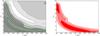 |
Fig. B.1 Joint distributions (scale radius and concentration) for the spherical model. Left panel: from dark to white gray-filled contours are 1, 2, and 3σ regions from the SL model, and green contours stand for the 68, 95, and 99% confidence levels for the Dyn model. Right panel: red-filled contours is the result of the SL+Dyn model, with the best solution depicted with a black star. |
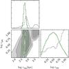 |
Fig. B.2 PDFs and contours of the parameters log c200 and log r200. From dark to white gray-filled contours are 1, 2, and 3σ regions from the SL model, and green contours stand for the 68, 95, and 99% confidence levels for the Dyn model. |
All Tables
All Figures
|
Fig. 1 Images of the group SL2S J02140-0535 at zspec = 0.44. Left: composite HST/ACS F814, F606, and F475 color image (22″ × 22″ = 125 × 125 kpc2) showing the central region of the group (from VMM11). Right: composite WIRCam J,Ks color image (22″ × 22″). |
| In the text | |
|
Fig. 2 CFHTLS i-band image with the luminosity density contours for SL2S J02140-0535. They represent 1 × 10⁶, 5 × 10⁶, and 1.0 × 10⁷L⊙kpc-2 from outermost to innermost contour, respectively. The red squares and circles show the location of the 24 confirmed members of the group, the squares represent the galaxies previously reported by Muñoz et al. (2013), and the circles represent the new observations. The black vertical line on the left represents 1 Mpc at the group rest frame. The inset in the top-right corner shows a 30″× 30″ CFHTLS false color image of the system. |
| In the text | |
|
Fig. 3 Completeness as a function of the radius in SL2S J02140-0535. C ~ 60% roughly constant up to 1 Mpc. |
| In the text | |
|
Fig. 4 Top panel: as mentioned in Sect. 3.3, the slit length was limited by the position of the arcs, hence producing poor sky subtraction. Left: observed spectrum of arc A (black continuous line). In gray we depict a starburst template from Kinney et al. (1996) shifted at z = 1.628, and we indicate a possible [OII]λ3727 emission line, and some sky lines, in blue (see Sect. 3.3). Right: observed spectrum of arc C (black continuous line), as before we depicted in gray the starburst template from Kinney et al. (1996), but shifted at z = 1.02. We indicated some characteristic emission lines, along with the sky lines in blue, but we omit for clarity the labels of the last lines. Bottom panel: two-dimensional spectra of arc A (with a color bar in arbitrary units). We note the [OII]λ3727 emission line. Below, we show the two-dimensional spectra of arc C, with two emission lines clearly identified: [OII]λ3727, and [OIII]λ4958.9. |
| In the text | |
|
Fig. 5 Left column: photometric redshift PDF for the selected arcs (see text). The dashed vertical lines correspond to the spectroscopic value. Right column: best-fit spectral energy distribution. Points represent the observed CFHTLS broadband magnitudes, and J and Ks from WIRCam. Vertical and horizontal error bars correspond to photometric error and wavelength range of each filter, respectively. |
| In the text | |
|
Fig. 6 Adaptively smoothed image of SL2S J02140-0535 in the 0.5−2.0 keV band. The X-ray contours in black are linearly spaced from 5 to 20 cts/s/deg2. |
| In the text | |
|
Fig. 7 PDFs and contours of the parameters c200 and rs. The three contours stand for the 68%, 95%, and 99% confidence levels. The values obtained for our best-fit model are indicated with a gray square and with vertical lines in the 1D histograms; the asymmetric errors are presented in Table 1. Top panel: results from the SL model. Middle panel: results from the Dyn model. Bottom panel: results from the SL+Dyn model. |
| In the text | |
|
Fig. 8 PDFs and contours of the parameters logrs and logr200. The three contours stand for the 68%, 95%, and 99% confidence levels. The values obtained for our best-fit model are indicated with a gray square and with vertical lines in the 1D histograms; the asymmetric errors are presented in Table 1. Top panel: results from the SL model. Middle panel: results from the Dyn model.Bottom panel: results from the SL+Dyn model. |
| In the text | |
|
Fig. 9 PDFs and contours of the parameters c200 and M200. The three contours stand for the 68%, 95%, and 99% confidence levels. The values obtained for our best-fit model are shown with a gray square and with vertical lines in the 1D histograms; the asymmetric errors are presented in Table 1. Top panel: results from the SL model. Middle panel: results from the Dyn model. Bottom panel: results from the SL+Dyn model. |
| In the text | |
|
Fig. 10 Joint distributions. Top panel: scale radius and concentration. Middle panel: log rs and log r200. Bottom panel: concentration and M200. Green-filled contours are 1, 2, and 3σ regions from the Dyn model. Gray contours stand for the 68, 95, and 99% confidence levels for the SL model. Red contours is the result of the SL+Dyn model with the best solution depicted with a red star. |
| In the text | |
|
Fig. 11 Distribution of mass, gas, and galaxies in SL2S J02140-0535, as reflected by the total mass derived from the combined lensing and dynamics analysis (magenta), the adaptively smoothed i-band luminosity of group galaxies (yellow), and the surface brightness from XMM observations (blue). The lensing mass contours (magenta lines) correspond to projected surface densities of 0.2 × 10⁹, 1.2 × 10⁹, and 7.4 × 10⁹ M⊙ arcsec-2. The size of the image is 1.5 × 1.5 Mpc. |
| In the text | |
|
Fig. 12 Two-dimensional projected mass as a function of the radius measured from the BGG. The green and blue shaded areas corresponds to the mass profile within 1σ errors for the SL+Dyn model and the weak lensing model reported in VMM11, respectively. The orange-shaded region shows the area where the arc systems lie. The two red triangles with error bars show two estimates (at 0.5 and 1 Mpc) of the weak lensing mass from Foëx et al. (2013). Black diamonds (shifted in r-0.05 for clarity) show the predicted mass calculated from the work of Lieu et al. (2016). Cyan diamonds (shifted in r+0.05 for clarity) are the masses calculated from Lieu et al. (2016) data, but assuming c200 = 10 (see text). We also depict with two arrows, our best rs (for c200 = 10), and the rs (for c200 = 2.7) reported in Lieu et al. (2016). |
| In the text | |
|
Fig. B.1 Joint distributions (scale radius and concentration) for the spherical model. Left panel: from dark to white gray-filled contours are 1, 2, and 3σ regions from the SL model, and green contours stand for the 68, 95, and 99% confidence levels for the Dyn model. Right panel: red-filled contours is the result of the SL+Dyn model, with the best solution depicted with a black star. |
| In the text | |
|
Fig. B.2 PDFs and contours of the parameters log c200 and log r200. From dark to white gray-filled contours are 1, 2, and 3σ regions from the SL model, and green contours stand for the 68, 95, and 99% confidence levels for the Dyn model. |
| In the text | |
Current usage metrics show cumulative count of Article Views (full-text article views including HTML views, PDF and ePub downloads, according to the available data) and Abstracts Views on Vision4Press platform.
Data correspond to usage on the plateform after 2015. The current usage metrics is available 48-96 hours after online publication and is updated daily on week days.
Initial download of the metrics may take a while.