| Issue |
A&A
Volume 532, August 2011
|
|
|---|---|---|
| Article Number | A34 | |
| Number of page(s) | 15 | |
| Section | The Sun | |
| DOI | https://doi.org/10.1051/0004-6361/201116518 | |
| Published online | 19 July 2011 | |
Magnetic confinement of the solar tachocline: II. Coupling to a convection zone
1
Laboratoire AIM Paris-Saclay, CEA/Irfu Université Paris-Diderot
CNRS/INSU,
91191
Gif-sur-Yvette,
France
e-mail: This email address is being protected from spambots. You need JavaScript enabled to view it.
2
LUTH, Observatoire de Paris, CNRS-Université Paris Diderot,
Place Jules
Janssen, 92195
Meudon,
France
Received:
14
January
2011
Accepted:
12
June
2011
Abstract
Context. The reason for the observed thinness of the solar tachocline is still not well understood. One of the explanations that have been proposed is that a primordial magnetic field renders the rotation uniform in the radiation zone.
Aims. We test here the validity of this magnetic scenario through 3D numerical MHD simulations that encompass both the radiation zone and the convection zone.
Methods. The numerical simulations are performed with the anelastic spherical harmonics (ASH) code. The computational domain extends from 0.07R⊙ to 0.97R⊙.
Results. In the parameter regime we explored, a dipolar fossil field aligned with the rotation axis cannot remain confined in the radiation zone. When the field lines are allowed to interact with turbulent unstationary convective motions at the base of the convection zone, 3D effects prevent the field confinement.
Conclusions. In agreement with previous work, we find that a dipolar fossil field, even when it is initially buried deep inside the radiation zone, will spread into the convective zone. According to Ferraro’s law of iso-rotation, it then imprints on the radiation zone the latitudinal differential rotation of the convection zone, which is not observed.
Key words: Sun: interior / Sun: rotation / magnetohydrodynamics (MHD) / convection / magnetic fields
© ESO, 2011
1. Introduction
The discovery of the solar tachocline can be considered as one of the great achievements of helioseismology (see Brown et al. 1989). In this layer the rotation switches from differential (i.e., varying with latitude) in the convection zone to nearly uniform in the radiation zone below. Its extreme thinness (less than 5% of the solar radius) came as a surprise (see Charbonneau et al. 1999) and has still not been explained properly.
Spiegel & Zahn (1992) made the first attempt to model the tachocline, and they showed that it should spread deep into the radiation zone owing to thermal diffusion. As a result, the differential rotation should extend down to 0.3 R⊙ after 4.5 Gyr, contrary to what is inferred from helioseismology (Schou et al. 1998; Thompson et al. 2003). The authors suggested one way to confine the tachocline, namely to counter-balance thermal diffusion by an anisotropic turbulence, which would smooth the differential rotation in latitude. This model was successfully simulated in 2D by Elliott (1997).
Gough & McIntyre (1998) (GM98 hereafter) argued that such an anisotropic turbulent momentum transport is not able to erode a large-scale latitudinal shear, citing examples from geophysical studies (see Starr 1968 and more recently Dritschel & McIntyre 2008 for a comprehensive review). For instance, the quasi-biennal oscillation in the Earth’s stratosphere arises from the anti-diffusive behavior of anisotropic turbulence. But the question is hardly settled because Miesch (2003) found in his numerical simulations that this turbulence is indeed anti-diffusive in the vertical direction, but the shear is reduced in latitude. Similar conclusions were reached through theoretical ( analytical) studies by Kim (2005), Leprovost & Kim (2006), and Kim & Leprovost (2007).
Gough & McIntyre proposed an alternate model, in which a primordial magnetic field is buried in the radiative zone and inhibits the spread of the tachocline. This is achieved through a balance between the confined magnetic field and a meridional flow pervading the base of the convection zone. Such a fossil field was also invoked by Rudiger & Kitchatinov (1997) to explain the thinness of the tachocline and by Barnes et al. (1999) to interpret the lithium-7 depletion at the solar surface. Moreover, it would easily account for the quasi uniform rotation of the radiative interior, which the hydrodynamic model of Spiegel & Zahn does not (at least in its original formulation). However, one may expect that such a field would spread by ohmic diffusion, and that it would eventually connect with the convection zone, thus imposing the differential rotation of that zone on the radiation zone below.
In order to test the magnetic confinement scenario and to put constraints on the existence of such a primordial field, several numerical simulations of the solar radiation zone were performed by Garaud (2002) in 2D, and by Brun & Zahn (2006) (i.e., Paper I, hereafter BZ06) in 3D. These simulations exhibit a propagation of the differential rotation into the radiation zone (primarily in the polar region). The primordial magnetic field successfully connects to the base of the convection zone where the shear is imposed and, according to Ferraro’s law of iso-rotation (Ferraro 1937), the angular velocity is transmitted along the magnetic field lines from the convection zone into the radiative interior, much faster than it would through thermal diffusion. However, in the aforementioned calculations the base of the convection zone was treated as an impenetrable wall, i.e. radial motions could not penetrate in either direction (from top down or from bottom up). No provision was made for a meridional circulation originating in the convection zone that would penetrate into the radiation zone and could prevent the upward spread of the magnetic field. This penetration was taken into account in numerical simulations by Sule et al. (2005), Rudiger & Kitchatinov (2007), Garaud & Garaud (2008), in a model of the polar region by Wood & McIntyre (2007), and in simulations coupling the radiative zone to a convective zone by Rogers (2011) to properly represent the GM98 scenario. In most of these models, an axisymmetric and stationary meridional circulation was imposed at the top of the radiation zone, strong enough to bend the magnetic field lines of the primordial field. As could be expected, various profiles of meridional circulation resulted in different confinement properties, thus emphasizing the need for a more self-consistent approach. We thus propose here to treat the problem by letting a genuine convective envelope dynamically generate its meridional circulation and differential rotation and to study how these nonlinearly generated flows interact with a fossil field.
Our 3D simulations treat the nonlinear coupling of the convection and radiation zones, and the model includes all physical ingredients that play a role in the tachocline confinement (thermal and viscous diffusion, meridional circulation, convective penetration, solar-like stratification, magnetic fields, pumping,...). The paper is organized as follows. In Sect. 2 we describe the model we use to address the question of the magnetic confinement of the tachocline. We then emphasize in Sect. 3 the global trend of our simulations, and examine in Sect. 4 the dynamics of the tachocline region. Discussions and conclusions are reported in Sect. 5.
2. The model
We use the well tested ASH code (anelastic spherical harmonics, see Clune et al. 1999; Miesch et al. 2000; Brun et al. 2004). Originally designed to model solar convection, it has been adapted to include the radiation zone as well (see BZ06). With this code, Brun et al. (2011) performed the first 3D MHD simulations of the whole sun from r = 0.07 R⊙ to r = 0.97 R⊙ with realistic stratification, thus nonlinearly coupling the radiation zone with the convection zone. Convective motions at the base of the convective envelope (around r = 0.72 R⊙) penetrate into the radiative zone over a distance of about 0.04 R⊙, exciting internal waves that propagate over the entire radiative interior. The model maintains a radiation zone in solid body rotation and develops a differentially rotating convective zone that agrees well with helioseismic inversions (see Thompson et al. 2003). Although approximately three times thicker than observed, the simulated tachocline possesses both a latitudinal and radial shear. This tachocline spreads downward first because of thermal diffusion, and later because of viscous diffusion, as explained in SZ92. We do not assume here any anisotropic turbulent diffusivity to prevent the spread of the tachocline.
In the present work, we start our simulation from a mature model with a convection and a radiation zone. We then introduce an axisymmetric dipole-like magnetic field deep in the inner radiation zone. This work is meant to explore further the mechanisms considered in BZ06. The system is then evolved self-consistently through the interplay of fluid and magnetic field dynamics. As in Brun et al. (2011), the computational domain extends from rbottom = 0.07 R⊙ to rtop = 0.97 R⊙, and the boundary between radiation and convection zone is defined at rbcz ~ 0.715 R⊙, based on the initial entropy profile (see Figs. 1a and 1c) that is assumed to setup the background equilibrium state. We also define in Fig. 1c the convective overshooting depth rov ~ 0.675 R⊙ (see Sect. 2.2), the penetration depth of the meridional circulation rMC ~ 0.68 R⊙ (see Sect. 3.2), and the shear depth rshear ~ 0.58 R⊙ (see Sect. 2.2).
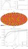 |
Fig. 1 a) Mean entropy gradient profile and zoom in the region where the entropy gradient changes sign. Entropy gradients are plotted in erg g-1 K-1 cm-1. b) Radial velocity on a spherical shell near the top of the convection zone (0.96 R⊙). Dark colors represent the downflows, while bright-yellow colors denote the upflows. c) rms velocities profiles at the interface between radiative and convective zones. The four vertical bars label the base of the convection zone (where the entropy gradient changes sign), the penetration depth of meridional circulation, the overshooting depth of convective motions, and the shear depth where differential rotation vanishes. |
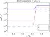 |
Fig. 2 Radial profile of the diffusivities used in our model (the values are given in cgs units). The κ profile corresponds to thermal diffusivity in Eq. (5), acting on the entropy fluctuations. |
The diffusivities (Fig. 2) were chosen to achieve a
realistic rotation profile in the convective envelope (see Sect. 2.2) by means of an efficient angular momentum redistribution by Reynolds
stresses (Brun & Toomre 2002; Miesch et al. 2006). In the radiation zone, they have the
same values as in BZ06 for consistency with previous studies. We define the following
step function to construct our diffusivity profiles: 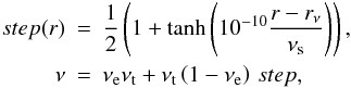 (1)where
rν = 4.7 × 1010 cm and
νs = 0.1 control the radial localization and the thickness of
the diffusivity jump. The parameter
νt = 8.0 × 1012cm2 s-1
controls the viscosity value in the convection zone and
νe = 10-3 controls the size of the viscosity jump.
The thermal and magnetic diffusivities are similarly defined with the same formulation as
for the step function, but with different
κt = 3.2 1013cm2 s-1,ηt = 1.6 × 1013cm2 s-1
and
κe = 0.25,ηe = 5.0 × 10⁻³
parameters to generate the diffusivity profiles plotted in Fig. 2. We used a
Nr × Nθ × Nϕ = 1024 × 256 × 512 grid
on massively parallel computers to compute this model. The Prandtl number
ν/κ is 10-3 in the
radiative zone and 0.25 in the convective zone; and the magnetic Prandtl number
ν/η is 0.1 in the radiative zone and
0.5 in the convective zone. The hierarchy between the various diffusivities is thus
respected even if their amplitudes are higher than in the Sun. As will be seen in
Sect. 3, they were chosen in a way that nonlinear
processes act efficiently in the regions of interest.
(1)where
rν = 4.7 × 1010 cm and
νs = 0.1 control the radial localization and the thickness of
the diffusivity jump. The parameter
νt = 8.0 × 1012cm2 s-1
controls the viscosity value in the convection zone and
νe = 10-3 controls the size of the viscosity jump.
The thermal and magnetic diffusivities are similarly defined with the same formulation as
for the step function, but with different
κt = 3.2 1013cm2 s-1,ηt = 1.6 × 1013cm2 s-1
and
κe = 0.25,ηe = 5.0 × 10⁻³
parameters to generate the diffusivity profiles plotted in Fig. 2. We used a
Nr × Nθ × Nϕ = 1024 × 256 × 512 grid
on massively parallel computers to compute this model. The Prandtl number
ν/κ is 10-3 in the
radiative zone and 0.25 in the convective zone; and the magnetic Prandtl number
ν/η is 0.1 in the radiative zone and
0.5 in the convective zone. The hierarchy between the various diffusivities is thus
respected even if their amplitudes are higher than in the Sun. As will be seen in
Sect. 3, they were chosen in a way that nonlinear
processes act efficiently in the regions of interest.
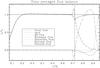 |
Fig. 3 Radial flux balance. In the convection zone, energy is mainly carried by the enthalpy flux; the entropy flux represents the flux carried by the unresolved motions. Note the penetration of convective motions below the convection zone (represented by the dashed line). |
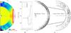 |
Fig. 4 a) Azimuthally and temporally averaged rotation frequency. Yellow denotes the rotation rate of the interior, red is the higher rotation rate and blue the lower rotation rate. b) Radial profile of rotation frequency at different latitudes. c) Meridional circulation in the radiation zone (left) and in the convection zone (right), evaluated from the poloidal mass flux averaged over time and longitude. Solid contours denote counterclockwise circulation, dashed contours clockwise circulation. |
2.1. Governing equations
ASH solves the 3D MHD set of Eqs. (2–6). It uses the anelastic approximation to
filter out the sound waves, and the LES approach (large eddy simulation) with
parameterization to take into account subgrid motions. The mean state is described by mean
profiles of density  ,
temperature
,
temperature  ,
pressure
,
pressure  ,
and entropy
,
and entropy  .
The reference state is taken from a thermally relaxed 1D solar structure model (Brun et al. 2002) and is regularly updated.
Fluctuations around the reference state are denoted without bars. The governing equations
are written in electromagnetic units, in the reference frame rotating at angular velocity
Ω0 = Ω0ez:
.
The reference state is taken from a thermally relaxed 1D solar structure model (Brun et al. 2002) and is regularly updated.
Fluctuations around the reference state are denoted without bars. The governing equations
are written in electromagnetic units, in the reference frame rotating at angular velocity
Ω0 = Ω0ez:
![Mathematical equation: \begin{eqnarray} \label{eq:mass_consrv} \boldsymbol{\nabla}\cdot\left(\bar{\rho} \vec{v}\right) &=& 0 \\ \label{eq:Maxw1} \boldsymbol{\nabla}\cdot \vec{B} &=& 0 \\ \bar{\rho}\left[\partial_{\rm t} \vec{v} + \left( \vec{v}\cdot \boldsymbol{\nabla} \right) \vec{v} + 2{\boldmath {\Omega_0}}\times \vec{v} \right] &=&-{\boldsymbol{\nabla}} P + \rho \vec{g} \nonumber \\ \label{eq:mom_conserv}+\frac{1}{4\pi}\left({\boldsymbol{\nabla}}\times \vec{B}\right)\times \vec{B} &-& {\boldsymbol{\nabla}}\cdot\mathbf{\mathcal{D}} - \left[{\boldsymbol{\nabla}}\bar{P}-\bar{\rho} {g} \right] \\ \bar{\rho}\bar{T}\left[\partial_{\rm t} S + \vec{v}\cdot{\boldmath \nabla}\left(\bar{S}+S\right) \right] &=& \boldsymbol{\nabla}\cdot\left[ \kappa_r\bar{\rho}c_p{\boldmath \nabla}\left(\bar{T}+T\right)\right. \nonumber \\ + \left. \kappa_{0}\bar{\rho}\bar{T}{\boldsymbol{\nabla}}\bar{S} + \kappa\bar{\rho}\bar{T}{\boldsymbol{\nabla}} S \right] &+& \frac{4\pi\eta}{c^2}\vec{J}^2 \nonumber \\ + 2\bar{\rho}\nu [ e_{ij}e_{ij} -\frac{1}{3}\left(\boldsymbol{\nabla}\cdot \vec{v}\right)^2 ] &+& \bar{\rho}\epsilon \label{eq:entropy_conserv} \\ \partial_{\rm t} \vec{B} = {\boldsymbol{\nabla}}\times\left( \vec{v}\times \vec{B}\right) &-& {\boldsymbol{\nabla}}\times\left(\eta{\boldsymbol{\nabla}}\times \vec{B}\right), \label{eq:inductiom_eq} \end{eqnarray}](/articles/aa/full_html/2011/08/aa16518-11/aa16518-11-eq38.png) where
v is the local velocity, B
the magnetic field, κ, ν and η are
respectively the effective thermal diffusivity, eddy viscosity, and magnetic diffusivity.
The radiative diffusivity κr is deduced from
a 1D model and adjusted in the radiative zone and in the overshooting layer to achieve an
equilibrated radial flux balance (see Fig. 3). The
thermal diffusion coefficient κ0 plays a role at the top of
the convective zone (where convective motions vanish) to ensure the heat transport through
the surface. This term proportional to d/dr
is part of our subgrid scale treatment in the convection zone. The unresolved flux only
acts in the upper part of the convection zone (see Fig. 3), and κ0 is chosen to be small enough that this
flux does not play any role in the radiative interior (besides eventual numerical
stabilization).
where
v is the local velocity, B
the magnetic field, κ, ν and η are
respectively the effective thermal diffusivity, eddy viscosity, and magnetic diffusivity.
The radiative diffusivity κr is deduced from
a 1D model and adjusted in the radiative zone and in the overshooting layer to achieve an
equilibrated radial flux balance (see Fig. 3). The
thermal diffusion coefficient κ0 plays a role at the top of
the convective zone (where convective motions vanish) to ensure the heat transport through
the surface. This term proportional to d/dr
is part of our subgrid scale treatment in the convection zone. The unresolved flux only
acts in the upper part of the convection zone (see Fig. 3), and κ0 is chosen to be small enough that this
flux does not play any role in the radiative interior (besides eventual numerical
stabilization).  is the rate of nuclear energy generation chosen to have the correct integrated luminosity
(see Brun et al. 2011).
J = (c/4π)∇ × B
is the current density, and the viscous stress tensor
is the rate of nuclear energy generation chosen to have the correct integrated luminosity
(see Brun et al. 2011).
J = (c/4π)∇ × B
is the current density, and the viscous stress tensor
 is defined by
 ![Mathematical equation: \begin{equation} \label{eq:visc_stress_tensor} \mathcal{D}_{ij} = -2\bar{\rho}\nu\left[e_{ij}-\frac{1}{3}\left({\boldsymbol{\nabla}}\cdot \vec{v}\right)\delta_{ij}\right] . \end{equation}](/articles/aa/full_html/2011/08/aa16518-11/aa16518-11-eq49.png) (7)The system is
closed by using the linearized ideal gas law:
(7)The system is
closed by using the linearized ideal gas law: 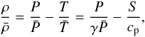 (8)with
cp the specific heat at constant pressure and
γ the adiabatic exponent.
(8)with
cp the specific heat at constant pressure and
γ the adiabatic exponent.
We chose rigid and stress-free conditions at the boundary shells for the velocity. We also imposed constant mean entropy gradient at the boundaries, matched the magnetic field to an external potential magnetic field at the top, and treated the bottom boundary as a perfect conductor.
2.2. Characteristics of the background model and choice of the initial magnetic field
Integrated solar models built with the ASH code that couple a deep radiative interior to a convective zone have been previously described in Brun et al. (2011); here we need only to stress some properties that are of particular interest for our study of the tachocline dynamics.
The starting point of our model is the choice of thermodynamic quantity profiles that will allow us to treat the convective and radiative zones together. Using a standard solar model calibrated to seismic data (Brun et al. 2002) computed by the CESAM code (Morel 1997), we chose to use the real solar stratification in the radiation zone and take a constant negative initial entropy gradient in the convection zone. These profiles are closely in agreement the guess profile after a Newton-Raphson solve. After setting a stable/unstable stratification, we perturbed the background state assuming a Rayleigh number well above the critical Rayleigh number for the onset of convection. A sample of the convective motions realized in the model is shown in Fig. 1b, where one can recognize the characteristic banana pattern near the equator and a patchy behavior at high latitudes (see Brun & Toomre 2002). We then let the model evolve toward a mature state in two steps. First we let the overshooting layer and the differential rotation develop. Then we sped up the thermal relaxation of the system by adding a bump on the radiative flux in the overshooting region (see Brun et al. 2011 for more details). Thanks to this procedure, we quickly achieved good radial flux balance (Fig. 3). The energy provided by nuclear reactions is transported through radiation in the radiation zone, and is essentially transported by the enthalpy flux in the convection zone. The overshoot region, defined here as the region of negative enthalpy flux, extends from rbcz = 0.715 R⊙ to rov = 0.675 R⊙, leading to dov ≈ 0.04 R⊙ ≈ 0.4 Hp (where Hp is the local pressure scale height). In the convection zone, the radiative flux quickly goes to zero, while viscous and kinetic energy fluxes tend to oppose the outward transport of heat of the enthalpy flux associated to the convective motions. Near the top of the domain, convective motions vanish due to our choice of impenetrable wall; thus the enthalpy flux decreases, and the energy is then transported by the entropy flux.
With our choice of diffusion coefficients (Fig. 2), the system reached a state of fully developed convection with a rotation profile that agreed well with the results of helioseismology (e.g. Thompson et al. 2003): the convection zone rotates faster at the equator than at the poles, and the rotation profiles are conical at mid-latitudes (see Fig. 4a). We display the radial profile of Ω at indicated latitudes in Fig. 4b. We clearly see the presence of a tachocline. Future work will aim at reducing the thickness of the jump of the diffusivities (Fig. 2) with a more flexible radial discretization (currently under development) to model a thinner hydrodynamic tachocline. Finally, the meridional circulation in the convection zone is composed by a major cell in each hemisphere (Fig. 4c), and by smaller counter-rotating cells at the poles.
When the hydrodynamic model reached an equilibrated state (as reported in Brun et al. 2011), we introduced a dipolar axisymmetric
magnetic field buried in the radiative zone. It is set to vanish at the base of the
tachocline, below the level where differential rotation starts, and we imposed the
functional form 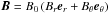 ,
with
,
with 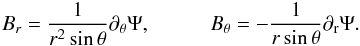 (9)Ψ(r,θ)
is constant on field lines. As in BZ06, we chose
(9)Ψ(r,θ)
is constant on field lines. As in BZ06, we chose 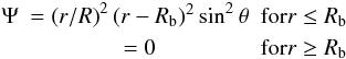 (10)where
Rb = 0.57 R⊙ is the bounding
radius of the confined field. According to Gough &
McIntyre (1998), the amplitude of the magnetic field controls the scalings of the
tachocline and the magnetopause (a thin layer of intense magnetic field). With our choice
of parameters, these scalings would require an initial seed magnetic field of the order of
104 G (i.e.,
δ/R ~ Δ/R ~ 10-2,
in GM98’s notations). Here we set B0 to
4.2 × 10⁴ G to be at equipartition of energy in the
radiative zone between magnetic energy and total kinetic energy in the rotating reference
frame.
(10)where
Rb = 0.57 R⊙ is the bounding
radius of the confined field. According to Gough &
McIntyre (1998), the amplitude of the magnetic field controls the scalings of the
tachocline and the magnetopause (a thin layer of intense magnetic field). With our choice
of parameters, these scalings would require an initial seed magnetic field of the order of
104 G (i.e.,
δ/R ~ Δ/R ~ 10-2,
in GM98’s notations). Here we set B0 to
4.2 × 10⁴ G to be at equipartition of energy in the
radiative zone between magnetic energy and total kinetic energy in the rotating reference
frame.
We stress here that such a magnetic field is subject to the high m Tayler instability (see Tayler 1973; Brun & Zahn 2006; Brun 2007) because it has no azimuthal component to start with. One could prefer to choose a mixed poloidal/toroidal magnetic field because it is the only possible stable configuration of magnetic field in radiative stellar interiors (Tayler 1973; Braithwaite & Spruit 2004; Duez & Mathis 2010). However, this has no consequences for the problem at hand, because a toroidal field quickly develops and stabilizes the magnetic configuration.
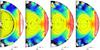 |
Fig. 5 Poloidal snapshots of azimuthal averages of the rotation profile (colored background) and magnetic field lines (black). Color table is the same as in Fig. 4a. |
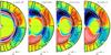 |
Fig. 6 Poloidal snapshots of ⟨ Bϕ ⟩ (colored background) and instant meridional circulation (black lines). Initially, the magnetic field is purely poloidal. The first figure on the left is taken just after the beginning iteration (not the same time as in Fig. 5a) to demonstrate how the longitudinal magnetic field is primarily created. Red is the positive magnetic field, and blue the negative magnetic field. In order to display the azimuthal magnetic field in the radiation zone and the convection zone (where it is much weaker), a logarithmic scale was used for the color table. The two white lines indicate the base of the convection zone rbcz and the shear depth rshear (cf. Fig. 1c). |
3. General evolution
The first evolutionary phase of our simulation is similar to that in BZ06, with the magnetic field diffusing through the tachocline. But here we follow its evolution as it enters into the convection zone, and we witness the back-reaction of convective motions on the field. The outcome is the same in the end, as we shall see in Sect. 3.1. More details on tachocline dynamics are given in Sect. 3.2.
3.1. Global evolution of the magnetic field
We started the simulation by burying the primordial field deep within the radiative interior and below the tachocline. As the simulation proceeded, the field expanded through the tachocline into the convection zone, where it experienced a complex evolution under the combined action of advection by the convective motions, shearing through the differential rotation and ohmic diffusion. It finally reached the domain boundary (Fig. 5b) where it connected to an external potential field.
The distortion of the field lines produces magnetic torques that force the angular velocity Ω to tend toward constant along the field lines of the mean poloidal field, thus leading to Ferraro’s law of iso-rotation. This is illustrated in Fig. 5, where the iso-contour Ω = 414nHz (i.e., the initial rotation frequency of the whole radiation zone) is thicker and more intense. As a result, the radiation zone slows down under the influence of the magnetic torques (Fig. 5c). Our choice of torque-free boundary conditions implies that the total angular momentum is conserved. It is extracted from the radiative zone and redistributed within the convective envelope.
 |
Fig. 7 Three-dimensional views of the longitudinal velocity in the rotating frame. Red are the positive velocities, and blue the negative velocities. Picture a) is the initial time where we added the magnetic field, and picture b) is taken after two solar rotation periods. Picture c) is taken much later in the simulation, when the magnetic layer became stable. Colored lines are the magnetic field lines we constructed from only a few seed points to be able to distinguish them. Dark colors denote lower magnetic field intensity. Note that for the third image, we only put in seed points at one longitude value to distinguish the field lines that explore almost the entire ϕ domain in the radiation zone. |
 |
Fig. 8 Three-dimensional views from the north pole. The left picture corresponds to Fig. 7c, and the two following snapshots are taken 2 and 4 days later. We reversed the color table of the field lines to emphasize their movement. The green arrows indicate the movement of three field lines during this period. |
As the initial magnetic field meets the angular velocity shear, toroidal magnetic field is created in the tachocline region via the Ω-effect (see Moffatt 1978), consistent with the magnetic layer introduced in GM98. Near the initial time (Fig. 6a) the the magnetic layer exhibits a mixed l = 1,l = 3 configuration. The axisymmetric longitudinal magnetic field then presents a l = 3 structure (Fig. 6b), consistent with the action of differential rotation on the dipolar magnetic field through the induction equation. This layer of axisymmetric azimuthal magnetic field spreads downward, accompanying the spread of differential rotation (Figs. 6c–d). We also observe that the upper radial localization of maximum azimuthal magnetic field remains remarkably localized at the base of our initial tachocline. Some azimuthal field does penetrate into the convective envelope, partly because of some local Ω-effect that is at work in this region.
Meridional circulations exist in the radiative and convective zones and are self-consistently generated by the convective motions and local dynamics (Fig. 6). Observe that the evolution of the magnetic layer greatly perturbs the pattern of the meridional circulations in the radiative zone. Comparing Fig. 6 to the hydrodynamic model (Fig. 4c), we observe that even if temporal averages of the meridional circulation produce large hemispherical cells in the convection zone, the instantaneous pattern of this flow is multicellular both in longitude and latitude. Those 3D motions are unable to prevent the magnetic field from spreading into the convective zone, in contrast to what GM98 and Garaud & Garaud (2008) proposed in their 2D scenario. Note that Rogers (2011) confirm the absence of magnetic field confinement in recent 2D simulations, where the author coupled a radiative interior to a convective envelope.
Azimuthally averaged views can mislead the reader here bacause from those figures one cannot deduce the real impact of the turbulent convective motions on the magnetic field. Figure 7 displays 3D visualizations that emphasize at the same time the advective and diffusive processes that act on the magnetic field in the convective zone. Magnetic field lines are twisted and sheared by convective motions, but still the magnetic field connects the radiative and convective zones. One clearly observes the mostly horizontal magnetic layer in the tachocline on Fig. 7c. In that panel also the radiation zone starts to show the “footprint” of the differential rotation of the convection zone. In order to follow one particular field line, we display in Fig. 8 a 3D rendering time evolution using a high sampling cadence, viewed from the north pole. We observe that particular field lines (labeled A, B, and C) are strongly influenced by convective motions and exhibit a complex behavior, far from just simple diffusion. The primary importance of 3D motions will also be discussed in Sect. 3.2.
We stress here that the magnetic field lines first penetrate into the convective zone through the equator. One may wonder how this can be achieved in spite of the magnetic pumping (see Tobias et al. 2001; Weiss et al. 2004) that should be acting in this region. Let us mention several reasons why the magnetic pumping may not be efficient enough in our simulation, and by extension perhaps in the Sun:
-
•
Magnetic pumping has been proven to be much less efficientwhen strong rotation is present and enhances horizontal mixing.This corresponds to a low Rossby number regime, which is thecase for the Sun and our simulation. Indeed, our Rossby numberRo = ωrms/2Ω varies from 0.1 to 1 in the convection zone.
-
•
It has also been proven to be much less efficient as the underlying region (here the tachocline) is more stably stratified. We use here a realistic (strong) solar-like stratification.
-
•
The meridional circulation tends to advect the magnetic field upward at the equator, opposing the effect of the magnetic pumping. However, our simulation is perhaps not turbulent enough to counterbalance this effect, even though Rm > 1.
-
•
Our relatively high diffusivities may facilitate the connection between the two zones by favoring the field lines’ expansion. Nevertheless, it is also known that diffusion helps the “slipping” of the field lines (e.g., Zanni & Ferreira 2009 from ideal flux frozen scenario). This implies that even though the field lines have pervaded into the convection zone, they may not be efficiently enough anchored to transport angular momentum. More details will be given in Sect. 3.2.
-
•
The nature of penetration at the base of the convection zone is influenced by the Peclet number. In our case, the Peclet number is on the order of 1 at the base of the convection zone, implying a regime of overshooting rather than of penetrative convection (Zahn 1991). This translates into a more extended region of mixing than what is occurring in the Sun. Hence, the motions in our simulation are likely to be more vigorous at rov.
For all these reasons, the magnetic pumping near the equator in a fossil buried magnetic field scenario (Wood & McIntyre 2011) is quite complex and cannot be taken for granted as a mechanism to impermeably confine an inner magnetic field near the equator (detailed magnetic field evolution may be found in Sect. 3.2).
In order to watch how the primordial magnetic field manifests its presence in the convective zone, we tracked the evolution of Br near the surface (at r = 0.96 R⊙). Our choice of parameters (Pm = 0.5) for this simulation prevents the development of a dynamo-generated magnetic field in the convection zone because the resulting magnetic Reynolds number is less than one hundred there. The threshold for dynamo action is likely to be above that value, as shown by Brun et al. (2004). As a consequence, the presence of a magnetic field at the surface of the model (as seen in Fig. 9) is solely caused by the spreading and reshuffling of the inner magnetic field through the convective envelope. Since no dynamo action is operating in the model, the magnetic field decays on an ohmic time scale and will eventually vanish. However, we did not run the simulation long enough to access this decaying phase across the whole Sun. We also stress that the ratio ME/KE is only few 10-3 throughout the convection zone during the late evolution of our model; it is still far too low to observe any influence of the magnetic field on the convective patterns (see Cattaneo et al. 2003). Note that the non-axisymmetric pattern of Br in Fig. 9 is strongly correlated with vr, the vertical velocity pattern, with opposite sign of Br in the northern and southern hemispheres. Because the latitudinal derivative of vr changes sign at the equator, we deduce that it is the shear term (B·∇)v of the induction equation that dictates the evolution of Br in the convection zone. An interesting diagnostic is provided by reconstructing (with a potential field extrapolation) the magnetic field outside our simulated star, up to 2 R⊙ (Fig. 10). One easily recognizes the magnetic layer in the tachocline and the rapidly evolving magnetic field in the convection zone. The reconstructed outer magnetic field looks mainly dipolar and does not give any hints for its complicated inner structure.
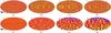 |
Fig. 9 Time evolution of vr and Br for the shell r = 0.96 R⊙. The different times are exactly the same as in Fig. 5. We subtracted the m = 0 component for Br. Dark colors denote negative velocities and radial magnetic field, and bright colors positive velocities and radial magnetic field. |
As mentioned above, our initial magnetic field is subject to high m instabilities because it starts as a purely poloidal field. Quickly the development of a toroidal component stabilizes the poloidal field, resulting in a complex poloidal-toroidal topology. In the magnetic layer, the azimuthal component of the toroidal field can locally be much larger than the poloidal field. Such a toroidal field is subject to low m instabilities (e.g. Tayler 1973; Zahn et al. 2007; Brun 2007). We observe the recurring of the m = 1 pattern at high latitudes on Fig. 11d. The profiles of the horizontal components of the magnetic field are shown in Figs. 11a and 11c. In the two right panels of Fig. 11, we subtracted the axisymmetric part of the field to render the instability more obvious. Note also that at the time chosen to generate the figure, the longitudinal component of the magnetic field is ten times stronger than its latitudinal component.
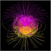 |
Fig. 10 Magnetic field lines from the center to the corona. For r > 0.96R⊙, a potential extrapolation is assumed. This snapshot is taken at the same time as Fig. 9g. The two very transparent spherical shells are set at r = 0.62 R⊙ and r = R⊙, we display in them the contours of the non-axisymmetric Bϕ and total Br. Magenta denotes the positive radial magnetic field, and yellow denotes the negative radial magnetic field. |
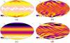 |
Fig. 11 Shell slices of the horizontal components of the magnetic field at r = 0.60 R⊙ in the late evolution of our model. Left figures represent the full fields, while the azimuthal mean was substracted in the right figures. Dark colors denote negative magnetic fields, and bright colors positive magnetic fields. |
3.2. Tachocline and local magnetic field evolution
Previous studies of the GM98 scenario have shed light on the importance of the penetration of the meridional circulation into the tachocline (Sule et al. 2005; Garaud & Garaud 2008). Numerical simulations in 2D have shown that this large-scale flow was able to deflect the magnetic field, and could prevent it from entering into the convection zone. We plot in Fig. 12 the meridional circulation patterns realized in the bulk of the tachocline. We observe both the meridional circulation penetration (coming from above rbcz ~ 0.72 R⊙), and the meridional circulation cells generated in the tachocline and at the top of the radiation zone. In our model, the meridional circulation penetrates approximately 4% of the solar radius below the base of the convection zone. The rms strength of the meridional velocity (shown with a logarithmic colormap) strongly decreases with depth in the tachocline. For instance, the meridional velocity loses three orders of magnitude over 0.03 solar radius by dropping from 18 m s-1 to 0.06 m s-1 near the poles at the base of the convective zone (see also Fig. 1c). Again, because our Peclet number is on the order of 1, this penetration is likely overestimated.
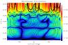 |
Fig. 12 Zoom of the time-averaged meridional circulation pattern before the introduction of the magnetic field in the tachocline area. The stream function is plotted in iso-contours, solid lines denoting clockwise circulation profiles, and dotted lines anti-clockwise. The background color map corresponds to the rms strength of the meridional circulation flow in m s-1 with a logarithmic scale. Red colors denote the strongest downflows. |
To evaluate the impact of the flow on the magnetic field evolution in the penetrative layer, we computed the magnetic Reynolds number Rm = VrmsΔ/η, where Vrms is the total rms velocity, Δ the convective penetration depth under the convection zone, and η the magnetic diffusivity. We take Δ = rbcz − rov ≈ 0.04 R⊙ (see Figs. 1c and 12). We obtained a magnetic Reynolds number on the order of 1 to a few in this penetration zone. This means that we are in a regime where shear and advection are on the order of, or slightly greater than diffusion in the magnetic field evolution equation. Different definitions of the magnetic Reynolds number may lead to different values. Indeed, if one retains only the radial component of the velocity field (i.e., in the sense of Garaud & Garaud 2008) or only the meridional component of the flow, we obtain a magnetic Reynolds number slightly lower than one. Conversely, if one uses the total radius of the star (i.e., in the sense of Sule et al. 2005), we obtain much higher Reynolds number values. In the end, it is the relative amplitude and the spatial structure of the various terms in the induction equation at any given location that actually determine the evolution of the system. The quantitative analysis of those terms demonstrates that we are in an advective regime, as will be seen in Figs. 13-16.
In addition, we also simulated the evolution of the same magnetic field in a purely diffusive case (i.e., without any velocity field). The evolution of the magnetic field deep in the radiation zone, i.e., below rov, is equivalent in the two simulations and is dominated by diffusion, its amplitude decreasing with the square root of time. However, the penetration of the magnetic field into the convective zone is faster in the full MHD case, as will be seen in Fig. 15.
In order to demonstrate the role played by time-dependent 3D convective motions and
nonlinearities in our simulation, we now turn to a detailed analysis of the evolution of
the mean poloidal and toroidal fields. Following Brown
et al. (2010), we first evaluate the different terms that contribute to the
creation and maintenance of the axisymmetric latitudinal magnetic field
⟨ Bθ ⟩ . It is essentially amplified by
shear, transported by advection, and opposed by diffusion. Starting from the induction
equation, one may write  (11)with
PMS and PMA representing the
production by the mean shearing and advecting flows, PFS and
PFA by fluctuating shear and advection,
PC by compression, and PMD by
mean ohmic diffusion. The symbol ⟨ ⟩ stands for azimuthal average. Those six terms are
(11)with
PMS and PMA representing the
production by the mean shearing and advecting flows, PFS and
PFA by fluctuating shear and advection,
PC by compression, and PMD by
mean ohmic diffusion. The symbol ⟨ ⟩ stands for azimuthal average. Those six terms are
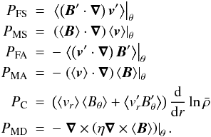 (12)These
definitions are then easily transposed to the radial and azimuthal components of the
magnetic field.
(12)These
definitions are then easily transposed to the radial and azimuthal components of the
magnetic field.
We plot in Figs. 13–14 the mean latitudinal field ⟨ Bθ ⟩ and the various terms of the right hand side of Eq. (12)at two instants in the simulation. We first show in Fig. 13 the early phase of evolution of ⟨ Bθ ⟩ , and a later phase of evolution in Fig. 14. At radius r = 0.6 R⊙ (i.e., deeper than rov), we initially observe two trends. First, the mean advective and shear contributions effectively cancel one another, possibly because of our choice of impenetrable and perfect conductor lower boundary condition (⟨Vr⟩ = 0 and ⟨Bθ⟩ = 0 at r = rbot). The same effect is observed for the ⟨ Br ⟩ component (not shown here). Second, because those two terms cancel each other, it is the magnetic diffusion that dictates the evolution of ⟨ Bθ ⟩ in this deep region. This is not a surprise, considering our diffusivity values and the lack of strong motions in this deep (inner) part of the model.
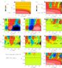 |
Fig. 13 Major terms of production of ⟨ Bθ ⟩ . The abscissa spans the northern hemisphere, the ordinate is a zoom in the tachocline. The left color bar corresponds to instantaneous ⟨ Bθ ⟩ , while the right color bar stands for the nine other panels. The RHS panel is the sum of the panels e), h), j), and i), and represents the net evolution of the mean latitudinal magnetic field. Panels c, d), f), g), i), and j) correspond to PMS, PMA, PFS, PFA, PC, and PMD, respectively (see Eq. (12)). The panels e and h correspond to the sum of panels c) and d), and f) and g), respectively. Color levels are not linear in order to see at the same time the contributions of the terms in the different regions. Red colors denote the positive contribution to the magnetic field and blue colors the negative contributions. The two horizontal lines in each panel represent rbcz (dash) and rMC (dot-dash), as in Fig. 1c. |
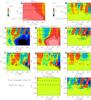 |
Fig. 14 Major terms of production of ⟨ Bθ ⟩ . The panels represent the same as in Fig. 13, but at a later time. |
On the other hand, the patterns are much more complicated in the penetration layer (between rov = 0.675 R⊙ and rbcz ~ 0.72 R⊙). Mean advection and shear are important, their sum (panel e) mainly acts at latitudes higher than 40°. Diffusion (panel j) acts everywhere in the penetration layer, but its action does not dominate the other contributions (panel b). The non-axisymmetric contributions (panels f, g, and h) are very important at latitudes lower than 60 in the penetration layer. Therefore, 3D motions are obviously responsible in our model for the failure of the magnetic field confinement below the convection zone at low latitude. This result contrasts with previous 2D studies, where these motions were not taken into account.
During the late evolution of our model (Fig. 14), the complex balance between axisymmetric motions, non-axisymmetric motions and diffusion is still operating in the penetration layer. We observe (panel a) that the magnetic field has completely pervaded the tachocline and extends into the convection zone. Again, the relative importance of the three panels e, h, and j indicates that diffusion is not the dominant process transporting the field. Indeed, we find again that the non-axisymmetric components significantly act at low latitude in this layer. We also note here that the levels of the color table were modified between Figs. 13 and 14, making the diffusive term (which is still operating around r = 0.6 R⊙) harder to be seen in panel j. Finally, we note that magnetic pumping is proven inefficient to confine the magnetic field at both times.
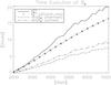 |
Fig. 15 Rms and absolute value of the latitudinal magnetic field amplitude evolution at r = 0.86 R⊙. The dotted and dashed lines correspond to the absolute value of the latitudinal component of the magnetic field in the downflows and in the upflows. We selected the downflows part by setting the magnetic field to zero at the points corresponding to a positive vr on the r = 0.86R⊙ spherical shell. We averaged the remaining values over the shell to obtain Bθ in downflows, and did the opposite for the upflows selection. The diamond line represents the evolution of the rms latitudinal magnetic field in the purely diffusive (test) case. |
In order to estimate the pumping, we plot in Fig. 15 the evolution of the amplitude of the latitudinal magnetic field at r = 0.86 R⊙ (in the convection zone) after its introduction. As previously seen, the amplitude rises. We plot on the same figure the evolution of the absolute value of the latitudinal component of the magnetic field both in the downflows (dot-dash) and in the upflows (triple dot-dash). We observe that the amplitude rises slower in the downflows than in the upflows. In addition, the temporal lag between the up- and downflow regions increases with time. This agrees with the action of magnetic pumping by downflows. However, it is a minor effect in the global evolution of the magnetic field.
We also plot in Fig. 15 the evolution of the rms latitudinal component of the magnetic field in the convection zone in both the nonlinear simulation discussed in the paper (solid line) and in another purely diffusive test case (diamonds). Once more, this stresses that the field evolution is different in our simulation than in the purely diffusive test case. The larger amplitude of Bθ in our convection simulation clearly demonstrates the role of advection in pulling the field inside the convection zone. The trends in Fig. 15 are similar between r = rov and rtop, i.e., in the whole convection zone and even in the penetration layer.
We may now also examine two different processes in the evolution of the azimuthal magnetic field: the creation and sustainment of the magnetic layer, and the expansion of the magnetic field into the convection zone. ⟨ Bϕ ⟩ is firstly created underneath the convection zone through the interaction between the dipolar magnetic field and the differential rotation around r = 0.62 R⊙. Diffusion slightly counterbalances the Ω effect, and advection does not act much in this layer. In order to illustrate these processes, we plot in Fig. 16 ⟨ Bϕ ⟩ and the right hand side terms from Eq. (12)(as in Fig. 13, but taken in the ϕ direction) during the early evolution of our model. Diffusion (panel j) opposes the creation of magnetic field by mean shear (panel c) in the magnetic layer (around 0.6 R⊙). Although the magnetic layer seems to remain radially localized, the magnetic field also exists in the convective zone. It has a much smaller amplitude than in the magnetic layer, but it is not negligible. We observe that ⟨ Bϕ ⟩ is preferentially created through the two terms of shear at latitudes below 40°. Notice that the non-axisymmetric velocity and magnetic field (panels f, g, and h) contribute equally with the axisymmetric terms to produce some magnetic field in the penetration layer (between the two horizontal lines). Diffusion generally tends to oppose the mean shear contribution PMS at all latitudes at the base of the convection zone, but does not act much in comparison with the other contributions in panels e and h. The mean advection opposes the creation of negative ⟨ Bϕ ⟩ above latitude 40°, which explains why the significant creation of coherent mean azimuthal magnetic field is localized at lower latitudes.
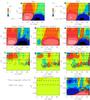 |
Fig. 16 Major terms of production of ⟨ Bϕ ⟩ in the tachocline. The various contributions are taken at the same time as Fig. 13, but using expressions corresponding to ⟨ Bϕ ⟩ . |
To summarize, we showed that the magnetic field evolution through the tachocline is caused by a complex interplay between shear and advection mechanisms. The diffusive process does not dictate the evolution of the magnetic field at the base of the convection zone, neither at the equator nor in the polar regions. Magnetic pumping is present, but inefficient. As a result, the magnetic field penetrates into the convection zone and does not remain confined. We stress here that the nonlinear term involving Maxwell and Reynolds stresses is a key and fundamental feature of our 3D simulation.
4. Balances in the tachocline
In order to understand the global rotation profile realized in our simulation (see Sect. 3), we study the MHD meridional force balance and the angular momentum transport equation in the following subsections. Even if the magnetic field does not modify the meridional force balance (Sect. 4.1), it is proven to be responsible for the outward transport of angular momentum in the mid- to high-latitude regions (Sect. 4.2).
4.1. MHD meridional force balance
Starting from the vorticity equation (Eq. (13)), one can derive the full meridional force balance in the general magnetic case (e.g., Fearn 1998; Brun 2005).
 (13)with
ωa = ∇ × v + 2Ω0
the absolute vorticity and
ω = ∇ × v
the vorticity in the rotating frame. In a statistically stationary state, Eq. (13)can be rewritten by taking the temporal and
azimuthal averages of the longitudinal component:
(13)with
ωa = ∇ × v + 2Ω0
the absolute vorticity and
ω = ∇ × v
the vorticity in the rotating frame. In a statistically stationary state, Eq. (13)can be rewritten by taking the temporal and
azimuthal averages of the longitudinal component: ![Mathematical equation: \begin{eqnarray} 2\Omega_0\frac{\partial \langle v_{\varphi} \rangle}{\partial z}&=& \underbrace{-\left\langle(\vec{\omega}\cdot \boldmath{\nabla})v_{\varphi} + \frac{\omega_{\varphi}v_r}{r} + \frac{\omega_{\varphi}v_{\theta}\cot\theta}{r} \right\rangle}_{{\rm \scriptsize{stretching}}} \nonumber \\ &+& \underbrace{\left\langle({\vec v}\cdot{\boldsymbol{\nabla}})\omega_{\varphi} +\frac{v_{\varphi}\omega_r}{r} + \frac{v_{\varphi}\omega_{\theta}\cot\theta}{r} \right\rangle}_{{\rm \scriptsize{advection}}} \nonumber \\ &+& \underbrace{- \langle\omega_{\varphi}v_r\rangle\frac{{\rm d}\ln \bar{\rho}}{{\rm d} r}}_{{\rm \scriptsize{compressibility}}} + \underbrace{\frac{g}{r c_{\rm p}}\frac{\partial \langle S \rangle}{\partial \theta} + \frac{1}{r \bar{\rho} c_{\rm p}}\frac{{\rm d}\bar{S}}{{\rm d}r}\frac{\partial \langle P \rangle}{\partial\theta} }_{\substack{{\rm \scriptsize{baroclinicity\,\,due\,\, to\,\, latitudinal}} \\ {\rm \scriptsize{entropy\,\, and \,\,pressure\,\, gradients}}}} \nonumber \\ &+& \underbrace{\frac{1}{r}\left[\frac{\partial}{\partial r}(r \langle{\cal A}_{\theta}\rangle) - \frac{\partial}{\partial \theta}\langle{\cal A}_r\rangle \right]}_{{\rm \scriptsize{viscous\,\, stresses}}} \nonumber \\ &+& \underbrace{\left\langle -\frac{1}{c\bar{\rho}}\left(\vec{B}\cdot\boldsymbol{\nabla}\right) j_\varphi - \frac{ j_r B_\varphi }{c\bar{\rho}r} - \frac{ j_\theta B_\varphi \cot\theta}{c\bar{\rho}r} \right\rangle }_{{\rm \scriptsize{magnetic\,\, torque\,\, 1}}} \nonumber \\ &+&\underbrace{\left\langle \frac{1}{c\bar{\rho}}\left(\vec{j}\cdot\boldsymbol{\nabla}\right) B_\varphi + \frac{B_r j_\varphi }{c\bar{\rho}r} + \frac{ B_\theta j_\varphi \cot\theta}{c\bar{\rho}r} \right\rangle }_{{\rm \scriptsize{magnetic\,\, torque\,\, 2}}} \nonumber \\ &+& \underbrace{ \frac{\left\langle B_r j_\varphi \right\rangle}{c\bar{\rho}}\frac{{\rm d}}{{\rm d}r}\ln{\bar{ \rho}} - \frac{\left\langle B_\varphi j_r \right\rangle}{c\bar{\rho}}\frac{{\rm d}}{{\rm d}r}\ln{\bar{ \rho}} }_{{\rm \scriptsize{compressibility\,\, 2}}} \label{eq:TW_balance} \end{eqnarray}](/articles/aa/full_html/2011/08/aa16518-11/aa16518-11-eq134.png) (14)where
(14)where
 and
and
![Mathematical equation: \begin{eqnarray} {\cal A}_r&=& \frac{1}{\bar{\rho}}\left[\frac{1}{r^2}\frac{\partial(r^2{\cal D}_{rr})}{\partial r}+\frac{1}{r\sin\theta}\frac{\partial(\sin\theta{\cal D}_{\theta r})}{\partial\theta} - \frac{ {\cal D}_{\theta \theta} + {\cal D}_{\phi \phi}}{r} \right] \nonumber \\ {\cal A}_{\theta}&=& \frac{1}{\bar{\rho}}\left[\frac{1}{r^2}\frac{\partial(r^2{\cal D}_{r\theta})}{\partial r}+\frac{1}{r\sin\theta}\frac{\partial(\sin\theta{\cal D}_{\theta \theta})}{\partial\theta} \right] \nonumber \\ && + \frac{1}{\bar{\rho}}\left[\frac{ {\cal D}_{\theta r} - cot \theta {\cal D}_{\phi \phi}}{r} \right]. \nonumber \end{eqnarray}](/articles/aa/full_html/2011/08/aa16518-11/aa16518-11-eq136.png) In
Eq. (14)we underlined different terms:
In
Eq. (14)we underlined different terms:
-
stretching represents the stretching of the vorticity by velocitygradients;
-
advection represents the advection of the vorticity by the flow;
-
compressibility represents the flow compressibility reaction on the vorticity;
-
 is
the baroclinic term, characteristic of non-aligned density and pressure gradients;
is
the baroclinic term, characteristic of non-aligned density and pressure gradients;
-
 is
part of the baroclinic term but arises from departures from adiabatic
stratification;
is
part of the baroclinic term but arises from departures from adiabatic
stratification; -
viscous stresses represent the diffusion of vorticity caused by viscous effects;
-
magnetic torques 1 and 2 represent the “shear” and “transport” of the magnetic field by the current;
-
compressibility 2 represents the component of the curl of the magnetic torque owing to compressibility of the flow.
The meridional force balance Eq. (14)helps understanding which physical effects are responsible for breaking the
Taylor-Proudman constraint of cylindrical differential rotation in the convection zone
(achieved for example with baroclinic flows, see Miesch
et al. 2006; Balbus et al. 2009; Brun et al. 2010). Indeed, considering a small Rossby
number and neglecting stratification, Reynolds, Maxwell, and viscous stresses, Eq. (14)reduces to  (15)which is the
original thermal wind equation (e.g., Pedlosky
1987; Durney 1999). The baroclinic term
induces motions that break the cylindrical rotation profile. In the model of Wood & McIntyre (2011), this balance is
considered in the polar regions. Compositional gradients and magnetic effects are added to
Eq. (15). This balance is of primary
importance in their magnetic confinement layer scaling. We therefore present below the
full meridional force balance of our model to evaluate the role played by all mechanisms
in the tachocline, except compositional effects.
(15)which is the
original thermal wind equation (e.g., Pedlosky
1987; Durney 1999). The baroclinic term
induces motions that break the cylindrical rotation profile. In the model of Wood & McIntyre (2011), this balance is
considered in the polar regions. Compositional gradients and magnetic effects are added to
Eq. (15). This balance is of primary
importance in their magnetic confinement layer scaling. We therefore present below the
full meridional force balance of our model to evaluate the role played by all mechanisms
in the tachocline, except compositional effects.
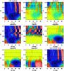 |
Fig. 17 Zoom around the tachocline of the different terms discussed in Eq. (14), averaged over longitude and two solar rotation periods during the late evolution of the model. Magnetic terms were increased by a factor 500 to make their structure more evident. |
Figure 17 displays the main contributing terms from Eq. (14)in our simulation. The magnetic terms were increased (by a factor of 500) to make them more visible. Surprisingly, they are too low to contribute to the meridional force balance, as such there is no “magnetic wind” (see Fearn 1998). As already noticed in Brun et al. (2011), the baroclinic term dominates the balance, especially under 0.65 R⊙, i.e., below the penetration. At the base of the convection zone (0.72 R⊙), all terms play a significant role. Stretching, advection, and viscous stresses compete against each other at low latitude, letting the baroclinic term dominate again. Near the pole, the balance is more complex, and viscous stresses (helped a little by stretching and advection) counteract the positive/negative pattern of the baroclinic term. The strict thermal wind balance expressed in Eq. (15)is thus not observed in the polar region. The magnetic terms are located in the magnetic layer where Bϕ is generated (see Sect. 3), and are negligible. Indeed, our magnetic field is far from being force-free, and the Lorentz force is non-zero in the three components of the momentum equation. The poloidal velocity is mainly driven by advection of convective motions and by baroclinic terms in the radiation zone. As a result, the poloidal magnetic field does not act much on the poloidal velocity. Note that this does not imply the opposite. We indeed observed (see Sect. 3.2) that the poloidal magnetic field evolution is dominated by advection and shear from convective motions. We did not recover the balance from Wood & McIntyre (2011), although we already have a sufficiently strong magnetic field to transport angular momentum, as seen in Sect. 4.2. Gyroscopic pumping is not operating efficiently near the polar region. There is a small downwelling, but it is not strong enough to modify the local dynamics (see Brun et al. 2011 for more details).
4.2. Angular momentum balance
Identifying processes that redistribute angular momentum in the bulk of the tachocline
gives us clues to understand how this layer evolves. Because we choose stress-free and
torque free magnetic boundary conditions, no external torque is applied to the system. As
a consequence, the angular momentum is conserved. Following previous studies (e.g., Brun et al. 2004), we examine the contribution of
different terms in the balance of angular momentum. Averaging the ϕ
component of the momentum Eq. (4) over
ϕ and multiplying it by rsinθ, we
obtain the following equation for the specific angular momentum
 :
:
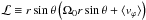
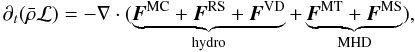 (16)where the different
terms correspond to contributions from meridional circulation, reynolds stress, viscous
diffusion, maxwell torque and maxwell stress. They are defined by
(16)where the different
terms correspond to contributions from meridional circulation, reynolds stress, viscous
diffusion, maxwell torque and maxwell stress. They are defined by 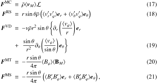 where
the subscript .M designates the meridional component of
v and B. In the previous
equations, we decomposed the velocity and the magnetic field into an azimuthally averaged
part ⟨ . ⟩ and ϕ-dependent part (with a prime). The
different contributions can be separated between radial (ℱr
along er) and latitudinal
(ℱθ along
eθ) contributions. We then
compute a radial flux of angular momentum defined by
where
the subscript .M designates the meridional component of
v and B. In the previous
equations, we decomposed the velocity and the magnetic field into an azimuthally averaged
part ⟨ . ⟩ and ϕ-dependent part (with a prime). The
different contributions can be separated between radial (ℱr
along er) and latitudinal
(ℱθ along
eθ) contributions. We then
compute a radial flux of angular momentum defined by  (22)where
(θ1,θ2) maybe
chosen to study a particular region of our simulation.
(22)where
(θ1,θ2) maybe
chosen to study a particular region of our simulation.
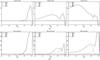 |
Fig. 18 Angular momentum redistribution in the radiative zone and the tachocline region. Panels a) are summed over θ1 = 60 and θ2 = 90 (north pole), and panels b) are summed over θ1 = 30 and θ2 = 60 (mid latitudes). The different fluxes are averaged approximately over six rotation periods. From left to right, the three plots correspond to the instants used to make Figs. 6a, c and d. Our magnetic field does not initially change the angular momentum balance. |
As emphasized in Sect. 3.1, magnetic field lines seem to be advected and diffused first outward and then poleward. In Fig. 18 we plot the different components of the radial angular momentum flux in the radiative zone and the tachocline at different times, summed over the polar region and at mid latitudes. Initially, the magnetic field is axisymmetric so Maxwell stresses do not contribute to the angular momentum balance. Because we chose a purely meridional magnetic field, there is no large-scale Maxwell torque. The radial angular momentum flux is then essentially carried by the meridional circulation in the radiative zone and is very weak (few percents of its value in the convective zone). Note, however, that internal waves are present in our simulation and may contribute to the transport of angular momentum (see Brun et al. 2011 for more details). In the tachocline, meridional circulation, Reynolds stress and viscous diffusion transport the angular momentum.
While the magnetic field more and more pervades the domain, a magnetic torque develops in the magnetic layer (along with Bϕ generation, see Figs. 5–6) at the top of the radiative zone both at high and mid latitudes. Angular momentum is then extracted by the Maxwell torque from the radiative zone (that locally rotates faster) into the tachocline (that locally rotates slower), slowing down the radiative interior. This torque tends to align the Ω contours with the poloidal magnetic field lines, thus bringing the system closer and closer to a state known as Ferraro’s law of isorotation. We remark in addition that the Maxwell torque operates initially in a wider part of the radiative zone in the polar region than at mid latitudes. Because the magnetic field primarily connects at the poles, it is natural that the transport of angular momentum by the magnetic field starts earlier in this region. One may also observe that this transport is more intense at mid-latitude, acknowledging that the magnetic field lines involve a magnetic field with much higher strength there. We stress again that the angular momentum is conserved in our simulation, meaning that the angular momentum lost in the radiative zone is redistributed in the convective zone.
We also observe that the magnetic torque applies essentially in the radiation zone and becomes negligible at the base of the convection zone. Because we are not yet in iso-rotation (see Fig. 5d), this may only be interpreted by the fact that Bϕ is weak in this region.
Because the first magnetic field lines that transport angular momentum are localized at mid- and high-latitudes, we observe here only a slow-down of the radiative interior. If we had continued this simulation, magnetic field lines would have connected the radiative zone to the convection zone near the equator. This would imply a speed-up of the radiative interior, consistent with the results from Brun & Zahn (2006). However, we do not show this later evolution because it does not add any useful information.
Viscosity seems to act substantially in the bulk of the tachocline, augmenting the angular momentum transport locally. This viscous transport is caused by the radial shear and the relatively high viscosity value used to meet numerical requirements. As a result, diffusive processes are over-evaluated in our simulation. Angular momentum transport like this would not contribute in the Sun, given the low viscosity of the solar plasma. In our case, both thermal and viscous diffusion processes are acting in our simulation thanks to our choice of Prandtl number (10-3) in the radiative zone. However, BZ06 showed that the simulated viscous spreading of the tachocline does not make much qualitative difference with the thermal spreading introduced by Spiegel & Zahn (1992).
The typical viscous diffusive time scale in our simulation is given by
τν = R2/ν ~ 2.2 × 10¹⁰ s
at the top of the radiative zone. As the magnetic field grows, the Alfvén time
 diminishes alike and magnetic
effects become more important than diffusion. The angular momentum balance analysis
emphasizes two phases in our simulation: a diffusive transport of angular momentum and the
action of large-scale Maxwell torque. This confirms that our magnetic field does not
prevent the spread of the tachocline, but on the contrary transports angular momentum
outwards and speeds the process up.
diminishes alike and magnetic
effects become more important than diffusion. The angular momentum balance analysis
emphasizes two phases in our simulation: a diffusive transport of angular momentum and the
action of large-scale Maxwell torque. This confirms that our magnetic field does not
prevent the spread of the tachocline, but on the contrary transports angular momentum
outwards and speeds the process up.
5. Discussion and conclusion
The existence of a magnetic field in the solar radiation zone has been the subject of a longstanding debate. Such a field, for example of fossil origin, could easily account for the uniform rotation of the radiative interior. It could also prevent the inward spread of the tachocline through thermal diffusion, as was proposed by Gough & McIntyre (1998). However, it has been argued that such a field would diffuse into the convection zone and imprint the latitude-dependent rotation of that region on the radiation zone below (which is not observed by helioseismology inversions).
This objection has indeed been confirmed by the calculations of Garaud (2002) and Brun & Zahn (2006). However, their simulations treated the top of the radiation zone as a non-penetrative boundary, which does not allow for a meridional flow that would originate in the convection zone and could oppose the diffusion of the magnetic field.
This restriction was lifted in the 2D simulations performed by Sule et al. (2005), Rudiger & Kitchatinov (2007), and Garaud & Garaud (2008), who showed that this meridional circulation could indeed prevent the magnetic field from diffusing into the convection zone. Very recent work in 2D (Rogers 2011) has studied the role of a fossil magnetic field in a simulation coupling a radiative and a convective zone. It confirms our result that the field is not confined at the base of the convection zone. However, the author does not find any magnetic transport of angular momentum, possibly because of a force-free state for the magnetic field. These 2D simulations assumed large-scale axisymmetric flows, unlike the three-dimensional motions of the real convection zone. For this reason we decided to treat the problem using a 3D code, with the best possible representation of the turbulent convective motions.
We showed by considering time-dependent 3D motions that the interior magnetic field does not stay confined in the radiative interior, but expands into the convection zone. Non-axisymmetric convective motions interact much differently with a dipolar-type magnetic field, as would a monolithic, single cell large-scale meridional circulation.
That our magnetic field is able to expand from the radiative interior into the convection zone results in an efficient outward transport of angular momentum through the tachocline, imposing Ferraro’s law of iso-rotation. It is likely a direct consequence of the non force-free configuration of our magnetic field that yields this efficient transport through the large-scale magnetic torque.
We are aware that our simulations are far from representing the real Sun, because of the enhanced diffusivities we had to use to meet numerical requirements. The overshooting convective motions are overestimated owing to our enhanced thermal diffusivity κ. The high solar Peclet number (lower κ) regime would make the flow amplitude drop even faster at the base of the convection zone, which would result in an even weaker meridional circulation velocity. This would not help the confinement of the magnetic field.
Although our enhanced magnetic diffusivity is quite large, we demonstrated (see Sect. 3) that our choice of parameters ensured that we are in the correct regime for magnetic field confinement, with advection dominating diffusion. Nevertheless, more efforts will be made in future work to increase the spatial resolution and to improve the subgrid-scales representation.
The initial magnetic topology may also be questioned. The gradient of our primordial dipolar field possesses a maximum at the equator. Because the field is initialized in the radiation zone where its evolution is diffusive, the magnetic field initially evolves faster at its maximum gradient location, i.e., at the equator. As a result, it first encounters the complex motions coming from the convection zone at the equator. Other simulations conducted with a modified topology to change the location of the maximum gradient (and thus the latitude where the magnetic field primarily enters the tachocline) led to similar results as those reported here.
Given the extension of our tachocline, the differential rotation is already initially present below the base of the convection zone before we introduce the magnetic field. A confined magnetic field would naturally erode this angular velocity gradient, though we do not know much about the real initial conditions. In our simulation the magnetic field opens into the convection zone, consequently there is no chance to obtain a solid rotator in the radiative zone because there is no confinement. In fact, our magnetic field lines primarily open at the equator. We point out that this is a major difficulty with the GM98 scenario: even if magnetic pumping can be a way to slow down the penetration of the magnetic field into the convective zone, it will not prevent it from connecting the two zones, and/or prevent the magnetic field lines from opening there. Furthermore, the meridional circulation is not a laminar uni-cellular flow in our 3D simulation. It has a complex instantaneous multicellular pattern, which affects the efficiency of a polar confinement.
We therefore conclude that a dipolar axisymmetric fossil magnetic field cannot prevent the spread of the solar tachocline. We intend to explore other mechanisms and different magnetic field topologies. Our 3D model will allow us to test non-axisymmetric configurations, e.g., an oblique and confined dipole.
Acknowledgments
The authors thank Nick Brummell, Gary Glatzmaier, Michael McIntyre and Toby Wood for helpful discussions. We are also grateful to Sean Matt for a careful reading of our manuscript. The authors acknowledge funding by the European Research Council through ERC grant STARS2 207430 (www.stars2.eu). 3D renderings in Figs. 7 and 8 were made with SDvision (see Pomarede & Brun 2010).
References
- Balbus, S. A., Bonart, J., Latter, H. N., & Weiss, N. O. 2009, MNRAS, 400, 176 [NASA ADS] [CrossRef] [Google Scholar]
- Barnes, G., Charbonneau, P., & MacGregor, K. B. 1999, ApJ, 511, 466 [NASA ADS] [CrossRef] [Google Scholar]
- Braithwaite, J., & Spruit, H. C. 2004, Nature, 431, 819 [NASA ADS] [CrossRef] [PubMed] [Google Scholar]
- Brown, B. P., Browning, M. K., Brun, A. S., Miesch, M. S., & Toomre, J. 2010, ApJS, 711, 424 [Google Scholar]
- Brown, T. M., Christensen-Dalsgaard, J., Dziembowski, W. A., et al. 1989, ApJS, 343, 526 [NASA ADS] [CrossRef] [Google Scholar]
- Brun, A. S. 2005, Habilitation in Physics (University of Denis-Diderot – Paris VII) [Google Scholar]
- Brun, A. S. 2007, Astron. Nachr., 328, 1137 [NASA ADS] [CrossRef] [Google Scholar]
- Brun, A. S., & Toomre, J. 2002, ApJ, 570, 865 [NASA ADS] [CrossRef] [EDP Sciences] [Google Scholar]
- Brun, A. S., & Zahn, J.-P. 2006, A&A, 457, 665 [NASA ADS] [CrossRef] [EDP Sciences] [Google Scholar]
- Brun, A. S., Antia, H. M., Chitre, S. M., & Zahn, J.-P. 2002, A&A, 391, 725 [NASA ADS] [CrossRef] [EDP Sciences] [Google Scholar]
- Brun, A. S., Miesch, M. S., & Toomre, J. 2004, ApJS, 614, 1073 [NASA ADS] [CrossRef] [Google Scholar]
- Brun, A. S., Antia, H. M., & Chitre, S. M. 2010, A&A, 510, A33 [NASA ADS] [CrossRef] [EDP Sciences] [Google Scholar]
- Brun, A. S., Miesch, M., & Toomre, J. 2011, ApJ, accepted [Google Scholar]
- Cattaneo, F., Emonet, T., & Weiss, N. 2003, ApJ, 588, 1183 [NASA ADS] [CrossRef] [MathSciNet] [Google Scholar]
- Charbonneau, P., Christensen-Dalsgaard, J., Henning, R., et al. 1999, ApJS, 527, 445 [NASA ADS] [CrossRef] [Google Scholar]
- Clune, T. L., Elliott, J. R., Miesch, M. S., Toomre, J., & Glatzmaier, G. A. 1999, Parrallel Computing, 25, 361 [Google Scholar]
- Dritschel, D. G., & McIntyre, M. E. 2008, J. Atmospheric Sci., 65, 855 [NASA ADS] [CrossRef] [Google Scholar]
- Duez, V., & Mathis, S. 2010, A&A, 517, A58 [NASA ADS] [CrossRef] [EDP Sciences] [Google Scholar]
- Durney, B. R. 1999, ApJ, 511, 945 [NASA ADS] [CrossRef] [Google Scholar]
- Elliott, J. R. 1997, A&A, 327, 1222 [NASA ADS] [Google Scholar]
- Fearn, D. R. 1998, Rep. Progress Phys., 61, 175 [Google Scholar]
- Ferraro, V. C. A. 1937, MNRAS, 97, 458 [Google Scholar]
- Garaud, P. 2002, MNRAS, 329, 1 [NASA ADS] [CrossRef] [Google Scholar]
- Garaud, P., & Garaud, J.-D. 2008, MNRAS, 391, 1239 [NASA ADS] [CrossRef] [Google Scholar]
- Gough, D. O., & McIntyre, M. E. 1998, Nature, 394, 755 [NASA ADS] [CrossRef] [Google Scholar]
- Kim, E.-J. 2005, A&A, 441, 763 [Google Scholar]
- Kim, E.-J., & Leprovost, N. 2007, A&A, 468, 1025 [NASA ADS] [CrossRef] [EDP Sciences] [Google Scholar]
- Leprovost, N., & Kim, E.-J. 2006, A&A, 456, 617 [NASA ADS] [CrossRef] [EDP Sciences] [Google Scholar]
- Miesch, M. S. 2003, ApJ, 586, 663 [NASA ADS] [CrossRef] [Google Scholar]
- Miesch, M. S., Elliott, J. R., Toomre, J., et al. 2000, ApJS, 532, 593 [NASA ADS] [CrossRef] [Google Scholar]
- Miesch, M. S., Brun, A. S., & Toomre, J. 2006, ApJ, 641, 618 [Google Scholar]
- Moffatt, H. K. 1978 (Cambridge University Press) [Google Scholar]
- Morel, P. 1997, A&ASS, 124, 597 [NASA ADS] [CrossRef] [EDP Sciences] [MathSciNet] [PubMed] [Google Scholar]
- Pedlosky, J. 1987, J. Phys. Oc., 17, 1978 [CrossRef] [Google Scholar]
- Pomarede, D., & Brun, A. 2010, Astronomical Data Analysis Software and Systems XIX. Proceedings of a conference held October 4–8, 434, 378 [NASA ADS] [Google Scholar]
- Rogers, T. M. 2011, ApJ, accepted [Google Scholar]
- Rudiger, G., & Kitchatinov, L. L. 1997, Astro. Nach., 318, 273 [CrossRef] [Google Scholar]
- Rudiger, G., & Kitchatinov, L. L. 2007, NJP, 9, 302 [NASA ADS] [CrossRef] [Google Scholar]
- Schou, J., Antia, H. M., Basu, S., et al. 1998, ApJ, 505, 390 [NASA ADS] [CrossRef] [Google Scholar]
- Spiegel, E. A., & Zahn, J.-P. 1992, A&A, 265, 106 [NASA ADS] [Google Scholar]
- Starr, V. 1968, Physics of negative viscosity phenomena (McGraw-Hill) [Google Scholar]
- Sule, A., Rudiger, G., & Arlt, R. 2005, A&A, 437, 1061 [NASA ADS] [CrossRef] [EDP Sciences] [Google Scholar]
- Tayler, R. J. 1973, MNRAS, 161, 365 [NASA ADS] [CrossRef] [Google Scholar]
- Thompson, M. J., Christensen-Dalsgaard, J., Miesch, M. S., & Toomre, J. 2003, ARA&A, 41, 599 [NASA ADS] [CrossRef] [Google Scholar]
- Tobias, S. M., Brummell, N. H., Clune, T. L., & Toomre, J. 2001, ApJ, 549, 1183 [NASA ADS] [CrossRef] [Google Scholar]
- Weiss, N. O., Thomas, J. H., Brummell, N. H., & Tobias, S. M. 2004, ApJ, 600, 1073 [NASA ADS] [CrossRef] [Google Scholar]
- Wood, T. S., & McIntyre, M. E. 2007, Unsolved Problems in Stellar Physics: A Conference in Honor of Douglas Gough. AIP Conf. Proc., 948, 303 [NASA ADS] [Google Scholar]
- Wood, T. S., & McIntyre, M. E. 2011, JFM, accepted [Google Scholar]
- Zahn, J.-P. 1991, A&A, 252, 179 [NASA ADS] [Google Scholar]
- Zahn, J.-P., Brun, A. S., & Mathis, S. 2007, A&A, 474, 145 [NASA ADS] [CrossRef] [EDP Sciences] [Google Scholar]
- Zanni, C., & Ferreira, J. 2009, A&A, 508, 1117 [NASA ADS] [CrossRef] [EDP Sciences] [Google Scholar]
All Figures
|
Fig. 1 a) Mean entropy gradient profile and zoom in the region where the entropy gradient changes sign. Entropy gradients are plotted in erg g-1 K-1 cm-1. b) Radial velocity on a spherical shell near the top of the convection zone (0.96 R⊙). Dark colors represent the downflows, while bright-yellow colors denote the upflows. c) rms velocities profiles at the interface between radiative and convective zones. The four vertical bars label the base of the convection zone (where the entropy gradient changes sign), the penetration depth of meridional circulation, the overshooting depth of convective motions, and the shear depth where differential rotation vanishes. |
| In the text | |
|
Fig. 2 Radial profile of the diffusivities used in our model (the values are given in cgs units). The κ profile corresponds to thermal diffusivity in Eq. (5), acting on the entropy fluctuations. |
| In the text | |
|
Fig. 3 Radial flux balance. In the convection zone, energy is mainly carried by the enthalpy flux; the entropy flux represents the flux carried by the unresolved motions. Note the penetration of convective motions below the convection zone (represented by the dashed line). |
| In the text | |
|
Fig. 4 a) Azimuthally and temporally averaged rotation frequency. Yellow denotes the rotation rate of the interior, red is the higher rotation rate and blue the lower rotation rate. b) Radial profile of rotation frequency at different latitudes. c) Meridional circulation in the radiation zone (left) and in the convection zone (right), evaluated from the poloidal mass flux averaged over time and longitude. Solid contours denote counterclockwise circulation, dashed contours clockwise circulation. |
| In the text | |
|
Fig. 5 Poloidal snapshots of azimuthal averages of the rotation profile (colored background) and magnetic field lines (black). Color table is the same as in Fig. 4a. |
| In the text | |
|
Fig. 6 Poloidal snapshots of ⟨ Bϕ ⟩ (colored background) and instant meridional circulation (black lines). Initially, the magnetic field is purely poloidal. The first figure on the left is taken just after the beginning iteration (not the same time as in Fig. 5a) to demonstrate how the longitudinal magnetic field is primarily created. Red is the positive magnetic field, and blue the negative magnetic field. In order to display the azimuthal magnetic field in the radiation zone and the convection zone (where it is much weaker), a logarithmic scale was used for the color table. The two white lines indicate the base of the convection zone rbcz and the shear depth rshear (cf. Fig. 1c). |
| In the text | |
|
Fig. 7 Three-dimensional views of the longitudinal velocity in the rotating frame. Red are the positive velocities, and blue the negative velocities. Picture a) is the initial time where we added the magnetic field, and picture b) is taken after two solar rotation periods. Picture c) is taken much later in the simulation, when the magnetic layer became stable. Colored lines are the magnetic field lines we constructed from only a few seed points to be able to distinguish them. Dark colors denote lower magnetic field intensity. Note that for the third image, we only put in seed points at one longitude value to distinguish the field lines that explore almost the entire ϕ domain in the radiation zone. |
| In the text | |
|
Fig. 8 Three-dimensional views from the north pole. The left picture corresponds to Fig. 7c, and the two following snapshots are taken 2 and 4 days later. We reversed the color table of the field lines to emphasize their movement. The green arrows indicate the movement of three field lines during this period. |
| In the text | |
|
Fig. 9 Time evolution of vr and Br for the shell r = 0.96 R⊙. The different times are exactly the same as in Fig. 5. We subtracted the m = 0 component for Br. Dark colors denote negative velocities and radial magnetic field, and bright colors positive velocities and radial magnetic field. |
| In the text | |
|
Fig. 10 Magnetic field lines from the center to the corona. For r > 0.96R⊙, a potential extrapolation is assumed. This snapshot is taken at the same time as Fig. 9g. The two very transparent spherical shells are set at r = 0.62 R⊙ and r = R⊙, we display in them the contours of the non-axisymmetric Bϕ and total Br. Magenta denotes the positive radial magnetic field, and yellow denotes the negative radial magnetic field. |
| In the text | |
|
Fig. 11 Shell slices of the horizontal components of the magnetic field at r = 0.60 R⊙ in the late evolution of our model. Left figures represent the full fields, while the azimuthal mean was substracted in the right figures. Dark colors denote negative magnetic fields, and bright colors positive magnetic fields. |
| In the text | |
|
Fig. 12 Zoom of the time-averaged meridional circulation pattern before the introduction of the magnetic field in the tachocline area. The stream function is plotted in iso-contours, solid lines denoting clockwise circulation profiles, and dotted lines anti-clockwise. The background color map corresponds to the rms strength of the meridional circulation flow in m s-1 with a logarithmic scale. Red colors denote the strongest downflows. |
| In the text | |
|
Fig. 13 Major terms of production of ⟨ Bθ ⟩ . The abscissa spans the northern hemisphere, the ordinate is a zoom in the tachocline. The left color bar corresponds to instantaneous ⟨ Bθ ⟩ , while the right color bar stands for the nine other panels. The RHS panel is the sum of the panels e), h), j), and i), and represents the net evolution of the mean latitudinal magnetic field. Panels c, d), f), g), i), and j) correspond to PMS, PMA, PFS, PFA, PC, and PMD, respectively (see Eq. (12)). The panels e and h correspond to the sum of panels c) and d), and f) and g), respectively. Color levels are not linear in order to see at the same time the contributions of the terms in the different regions. Red colors denote the positive contribution to the magnetic field and blue colors the negative contributions. The two horizontal lines in each panel represent rbcz (dash) and rMC (dot-dash), as in Fig. 1c. |
| In the text | |
|
Fig. 14 Major terms of production of ⟨ Bθ ⟩ . The panels represent the same as in Fig. 13, but at a later time. |
| In the text | |
|
Fig. 15 Rms and absolute value of the latitudinal magnetic field amplitude evolution at r = 0.86 R⊙. The dotted and dashed lines correspond to the absolute value of the latitudinal component of the magnetic field in the downflows and in the upflows. We selected the downflows part by setting the magnetic field to zero at the points corresponding to a positive vr on the r = 0.86R⊙ spherical shell. We averaged the remaining values over the shell to obtain Bθ in downflows, and did the opposite for the upflows selection. The diamond line represents the evolution of the rms latitudinal magnetic field in the purely diffusive (test) case. |
| In the text | |
|
Fig. 16 Major terms of production of ⟨ Bϕ ⟩ in the tachocline. The various contributions are taken at the same time as Fig. 13, but using expressions corresponding to ⟨ Bϕ ⟩ . |
| In the text | |
|
Fig. 17 Zoom around the tachocline of the different terms discussed in Eq. (14), averaged over longitude and two solar rotation periods during the late evolution of the model. Magnetic terms were increased by a factor 500 to make their structure more evident. |
| In the text | |
|
Fig. 18 Angular momentum redistribution in the radiative zone and the tachocline region. Panels a) are summed over θ1 = 60 and θ2 = 90 (north pole), and panels b) are summed over θ1 = 30 and θ2 = 60 (mid latitudes). The different fluxes are averaged approximately over six rotation periods. From left to right, the three plots correspond to the instants used to make Figs. 6a, c and d. Our magnetic field does not initially change the angular momentum balance. |
| In the text | |
Current usage metrics show cumulative count of Article Views (full-text article views including HTML views, PDF and ePub downloads, according to the available data) and Abstracts Views on Vision4Press platform.
Data correspond to usage on the plateform after 2015. The current usage metrics is available 48-96 hours after online publication and is updated daily on week days.
Initial download of the metrics may take a while.