| Issue |
A&A
Volume 686, June 2024
|
|
|---|---|---|
| Article Number | L13 | |
| Number of page(s) | 12 | |
| Section | Letters to the Editor | |
| DOI | https://doi.org/10.1051/0004-6361/202449949 | |
| Published online | 12 June 2024 | |
Letter to the Editor
FAUST
XV. A disc wind mapped by CH3OH and SiO in the inner 300 au of the NGC 1333 IRAS 4A2 protostar
1
ESO, Karl Schwarzchild Srt. 2, 85478 Garching bei München, Germany
e-mail: This email address is being protected from spambots. You need JavaScript enabled to view it.
2
INAF, Osservatorio Astrofisico di Arcetri, Largo E. Fermi 5, 50125 Firenze, Italy
3
Univ. Grenoble Alpes, CNRS, IPAG, 38000 Grenoble, France
4
National Radio Astronomy Observatory, 1003 Lopezville Rd, Socorro, NM 87801, USA
5
Institut de Radioastronomie Millimétrique (IRAM), 300 rue de la Piscine, 38406 Saint-Martin-d’Hères, France
6
Instituto de Radioastronomía y Astrofísica, Universidad Nacional Autónoma de México, A.P. 3-72 (Xangari), 8701 Morelia, Mexico
7
Instituto de Astronomía, Universidad Nacional Autónoma de México, Ciudad Universitaria, A.P. 70-264, Cuidad de México 04510, Mexico
8
The Institute of Physical and Chemical Research (RIKEN), 2-1, Hirosawa, Wako-shi, Saitama 351-0198, Japan
9
NRC Herzberg Astronomy and Astrophysics, 5071 West Saanich Road, Victoria, BC V9E 2E7, Canada
10
Department of Physics and Astronomy, University of Victoria, Victoria, BC V8P 5C2, Canada
11
Department of Astronomy, The University of Tokyo, 7-3-1 Hongo, Bunkyo-ku, Tokyo 113-0033, Japan
12
Leiden Observatory, Leiden University, PO Box 9513 2300 RA Leiden, The Netherlands
13
IRAP, Université de Toulouse, CNRS, CNES, UPS, Toulouse, France
14
Excellence Cluster ORIGINS, Boltzmannstraße 2, 85748 Garching bei Muünchen, Germany
15
Center for Astrochemical Studies, Max-Planck-Institut für extraterrestrische Physik (MPE), Gießenbachstr. 1, 85741 Garching, Germany
16
Centre for Frontier Science, Chiba University, 1-33 Yayoi-cho, Inage-ku, Chiba 263-8522, Japan
17
Department of Chemistry, University of Virginia, McCormick Road, PO Box 400319 Charlottesville, VA 22904, USA
18
The University of Texas at Austin, 2515 Speedway, Austin, TS 78712, USA
19
The Graduate University for Advanced Studies (SOKENDAI), Shonan Village, Hayama, Kanagawa 240-0193, Japan
Received:
12
March
2024
Accepted:
29
April
2024
Abstract
Context. Understanding the connection between outflows, winds, accretion, and discs in the inner protostellar regions is crucial for comprehending star and planet formation processes.
Aims. We aim to we explore the inner 300 au of the protostar IRAS 4A2 as part of the ALMA FAUST Large Program.
Methods. We analysed the kinematical structures of SiO and CH3OH emission with 50 au resolution.
Results. The emission arises from three zones: (i) a very compact and unresolved region (< 50 au) dominated by the ice sublimation zone, at ±1.5 km s−1 with respect to vsys, traced by methanol; (ii) an intermediate region (between 50 au and 150 au) traced by both SiO and CH3OH, between 2 and 6 km s−1 with respect to vsys, with an inverted velocity gradient (with respect to the large-scale emission), whose origin is not clear; (iii) an extended region (> 150 au) traced by SiO, above 7 km s−1 with respect to vsys, and dominated by the outflow. In the intermediate region, we estimated a CH3OH/SiO abundance ratio of about 120–400 and a SiO/H2 abundance of 10−8. We explored various possibilities to explain the origin of this region, such as, a rotating disc or inner envelope, a jet on the plane of the sky or precessing, and a wide-angle disc wind.
Conclusions. We propose that CH3OH and SiO in the inner 100 au probe the base of a wide-angle disc wind. The material accelerated in the wind crosses the plane of the sky, giving rise to the observed inverted velocity gradient, and sputtering the grain mantles and cores releasing CH3OH and SiO. This is the first detection of a disc-wind candidate in SiO, and the second ever in CH3OH.
Key words: stars: formation / ISM: jets and outflows / ISM: kinematics and dynamics / ISM: molecules / ISM: individual objects: IRAS 4A
The National Radio Astronomy Observatory is a facility of the National Science Foundation operated under cooperative agreement by Associated Universities, Inc.
© The Authors 2024
 Open Access article, published by EDP Sciences, under the terms of the Creative Commons Attribution License (https://creativecommons.org/licenses/by/4.0), which permits unrestricted use, distribution, and reproduction in any medium, provided the original work is properly cited.
This article is published in open access under the Subscribe to Open model. This email address is being protected from spambots. You need JavaScript enabled to view it. to support open access publication.
1. Introduction
Solar-like stars form from an accreting object deeply embedded in a dense envelope that drives bipolar jets. To allow the accretion from the disc onto the protostar, the angular momentum is extracted from the disc by jets or outflows, or disc winds (e.g., Shu et al. 1987). Understanding the accretion and ejection mechanisms and their impact on the physical and chemical structure of protostars is of paramount importance to our comprehension of the evolution of the forming star–planet(s) system.
Low-mass Class 0 protostars (∼104 yr; Andre et al. 2000) are the objects most often studied in investigations of both the accreting region and molecular outflows. Some protostars host hot (> 100 K), compact (< 100 au), dense (> 107 cm−3) regions rich in interstellar complex organic molecules (iCOMS; Herbst & Van Dishoeck 2009; Ceccarelli et al. 2017) – where the ice mantle sublimation dominates the chemistry – known as hot corinos (Ceccarelli 2004). However, not every protostar possesses a hot corino (e.g., De Simone et al. 2017, 2020a, 2022a; Belloche et al. 2020; Bouvier et al. 2022; Yang et al. 2020), and their physical and chemical structure is still not clear. Among the few known hot corinos, only a handful are spatially resolved (SVS13-A, HH212, IRAS 16293A, and B335; Bianchi et al. 2023; Lee et al. 2022a; Maureira et al. 2022; Okoda et al. 2022). Here, the iCOMs emission seems to probe different layers of the hot corino or selected regions associated to accretion shocks and/or hot spots.
On the other hand, jets and outflows driven by protostellar sources have been extensively studied, especially at scales larger than 500 au (e.g., Ray et al. 2007; Arce et al. 2007; Frank et al. 2014). However, their origin is still debated. Models predict that magneto centrifugal mechanisms extract material from the disc from two regions: close to the dust-truncation radius by a stellar magnetosphere (X-wind models: Shu et al. 1994; Arce et al. 2007; Shang et al. 2007), and at a wider range of radii outside this dust truncation radius (disc-wind models: Blandford & Payne 1982; Konigl & Pudritz 2000; Tsukamoto et al. 2023).
These winds have been considered as a solution to the angular momentum problem in the inner 50 au of the discs (e.g., Pascucci et al. 2023). However, only a handful of resolved disc wind observations are available (e.g., Tabone et al. 2017; Zhang et al. 2018; Louvet et al. 2018; de Valon et al. 2020; Lee et al. 2021a; López-Vázquez et al. 2024). Such observations provide crucial information (e.g., geometry, and kinematical and chemical structure) with which to constrain disc-wind models, and to retrieve their origin, and the interplay between accretion and ejection mechanisms.
In this Letter, we explore the SiO and CH3OH in the inner 300 au of the IRAS 4A2 protostar as part of the ALMA FAUST1 (Codella et al. 2021) Large Program. We study the kinematics of the gas in the transition zone between a possible disc and the ouflowing material, and present, for the first time, a wide disc-wind candidate for NGC 1333 IRAS 4A2 traced by SiO.
The target. NGC 1333 IRAS 4A is a very well-studied system in Perseus (∼300 pc away; Zucker et al. 2018). It is composed of two protostars: IRAS 4A1 (hereafter, 4A1), the brightest in millimetre (mm) continuum, and IRAS 4A2 (hereafter, 4A2), separated by about  (about 540 au; Looney et al. 2000; Santangelo et al. 2015; López-Sepulcre et al. 2017; Tobin et al. 2018). The two protostars are surrounded by a common envelope of about 8 M⊙ (Maury et al. 2019) and have a total bolometric luminosity of about 9 L⊙ (Kristensen et al. 2012; Karska et al. 2013). We note that the system is also known to show a ∼10% peak-to-peak variability – at submm wavelengths on year timescales – that can slightly affect the luminosity (Lee et al. 2021b; Mairs et al. 2024). Their mm dust emission is optically thick in the central region (Maury et al. 2019; Galametz et al. 2019; Li et al. 2017; Ko et al. 2020; Belloche et al. 2020) and completely obscures (for 4A1) or partially absorbs (for 4A2) the mm emission from iCOMs (De Simone et al. 2020a). The two protostars emit large bipolar jets or outflows, which have been deeply studied with several tracers, such as CO, SiO, SO, HCN, and some iCOMs (including methanol; e.g., Lefloch et al. 1998; Choi et al. 2011; Ching et al. 2016; De Simone et al. 2020b; Chuang et al. 2021). The southern lobes are blueshifted and the northern ones redshifted, and they cover a large velocity range (up to 60 km s−1; Choi 2005; Santangelo et al. 2015; Taquet et al. 2020). However, none of the previous studies resolve the inner 200 au (below
  ). The FAUST data provide a superb spatial resolution of 50 au, which allows us to explore these inner regions for the first time using selected chemical tracers.
CH3OH and SiO spectral and physical properties.
2. Observations
The observations of NGC 1333 IRAS 4A presented here are part of the Cycle 6 ALMA Large Program FAUST (PI. S. Yamamoto, 2018.1.01205.L). They were performed between October 2018 and September 2019 with baselines for the 12 m array between 15.1 m and 3.6 km. The bandpass and flux calibrator was J0237+2848, while J0336+3218 and J0328+3139 were used for phase calibration. The map phase centre is at right ascension (RA): (J2000) = 03h29m10s.539, declination (Dec): (J2000) = 31 . For this work, we used CH3OH (51, 4 − 41, 3A) and SiO (5 − 4) lines at 243.916 GHz and 217.105 GHz, respectively, in the high-resolution spectral windows (Δν = 0.123 kHz, corresponding to about 0.15 km s−1 and 0.17 km s−1 for CH3OH and SiO, respectively). The data were calibrated using the ALMA calibration pipeline within CASA2 with an additional calibration routine to correct for the Tsys normalisation issue3. After aligning data from different setups, phase-only self-calibration was performed on the continuum, which was generated using a careful manual detection of line-free channels. The continuum model was then subtracted from the visibilities prior to imaging the line data and a continuum image was then created in CASA. The resulting continuum-subtracted line cube was created by combining the two available ALMA-12 m configurations (i.e., C43-3, C43-6), to have the best angular resolution, and was imaged with the IRAM-GILDAS4 package using a 0.56 robust parameter5 with a resulting synthesised beam of
  (−13°) and
  (−21°) for the SiO and CH3OH spectral windows, respectively. The cubes were then primary beam corrected. We estimate an absolute flux error of 15%, which includes the calibration uncertainty and an additional error for the spectral baseline determination.
3. The kinematical structure of the IRAS 4A inner regions
Figure 1 shows the dust continuum emission at 1.3 mm of NGC 1333 IRAS 4A overlaid with the SiO 5–4 low-velocity emission (in the ranges ( − 6, −2) and ( + 2, +6) km s−1 with respect to the vsys; vsys = 6.8 km s−1; Choi 2001), with a zoom-in on SiO and CH3OH emission lines (listed in Table 1) at < 1″ (< 300 au) scale around IRAS 4A2. At large scale (above 1″ from IRAS 4A2, Fig. A.1), both SiO and CH3OH trace blueshifted emission in the south (up to −33 km s−1 with respect to vsys) and redshifted emission in the north (up to +35 km s−1 with respect to vsys). However, at small scales, the kinematics is different: below 300 au, both SiO and CH3OH emit in the velocity ranges (−6, −2) km s−1 and (+2, +6) km s−1 with respect to vsys (see also channel maps in Figs. B.1 and B.2) with a velocity gradient inverted with respect to the large scale. Specifically, CH3OH shows blueshifted emission towards the northeast and redshifted emission towards the southwest, which peaks at  from IRAS 4A2 and extends out to
  . The SiO emission has an S-shape structure that follows the continuum emission from the dust grains in the circumstellar envelope. In the inner 300 au, SiO shows both blueshifted and redshifted emission on both sides. However, in the inner
  (∼90 au), the SiO distribution resembles that of methanol, with an inverted velocity gradient with respect to the large-scale emission. At larger distances, that is, from
  to 1″, the southern lobe is only blueshifted (in agreement with the large scale), while the northern lobe is mainly redshifted with a tiny blueshifted contamination (which dominates closer to the vsys, at about −2 km s−1; see Fig. B.1). We also built position–velocity (PV) diagrams along the methanol and SiO PA and perpendicular to the emission (see Figs. D.1–D.3). The inversion of velocity is clearly shown, but the PV diagrams are limited in spatial (angular) resolution and do not reveal any other kinematical structure.
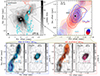 |
Fig. 1. Overview of the SiO and CH3OH emission toward IRAS 4A2 at different scales. Upper left: superposition of the 1.3 mm continuum (grey scale, up to 20% of maximum flux, with contours starting at 15σc with steps of 20σc, where σc = 8 × 10⁻² mJy beam−1) with SiO redshifted and blueshifted emission (salmon and cyan contours, respectively, from 3σ with steps of 4σ, where σ = 2 mJy beam−1 km s−1). Upper right: zoom onto IRAS 4A2. Superposition of the redshifted and blueshifted emission of SiO (salmon and cyan shaded contours) and CH3OH (red and blue contours). Contours start at 3σ with steps of 4σ for SiO and 5σ for CH3OH (σ = 2 mJy beam−1 km s−1). Beams are shown in the lower corners. Lower panels: blueshifted and redshifted emission for SiO and CH3OH shown separately. The beams are shown in the inner corner. In all panels, white and black stars mark the protostars IRAS 4A1 and IRAS 4A2. The redshifted and blueshifted emissions are integrated between +2 and +6 km s−1, and between −6 and −2 km s−1 with respect to the systemic velocity (vsys = +6.8 km s−1; Choi 2001), respectively. The moment 0 between −6 and 6 km s−1 for each species is shown in greyscale. |
Figure 2 shows the spectra extracted at the position of the CH3OH redshifted and blueshifted emission peaks (coordinate offsets reported in Table 1). The two peaks were identified as the pixel with the highest flux level in the integrated maps of CH3OH in the ( − 6, −2) km s−1 and ( + 2, +6) km s−1 ranges (see Fig. 1). The CH3OH spectrum peaks at low velocity (∼ ± 1.5 km s−1 with respect to vsys) and is likely dominated by the ice mantle sublimation region (i.e., the hot corino). The SiO spectrum instead peaks at higher velocity (about ±7 km s−1 with respect to vsys) and it is likely dominated by jet or outflow emission due to grain sputtering or shattering. In the ( − 6, −2) km s−1 and ( + 2, +6) km s−1 ranges, the spectra of CH3OH and SiO overlap. In these ranges, we observe the inverse velocity gradient. We measured the intensity ratio CH3OH/SiO (Table 1) integrated on the ( − 6, −2) km s−1 and ( + 2, +6) km s−1 ranges and the corresponding abundance ratio – estimated assuming local thermodynamic equilibrium (LTE), optically thin emission, and an excitation temperature of 100 K (typical for both hot corinos and shocked gas) – in the redshifted and blue- shifted emission peaks of both SiO and CH3OH. The emission peaks of SiO were identified – as for CH3OH – as the pixel with the highest flux level in the integrated maps (Fig. 1). We find that, in general, CH3OH is more abundant than SiO by about two orders of magnitude. Additionally, the moment 0 maps in Fig. 1 show that methanol peaks closer to the source than SiO in both blue and red ranges (by 0.1″, less than a beam). Even if unresolved, this spatial shift in the redshifted component seems to be significant. This is supported by the fact that the CH3OH/SiO integrated intensity and abundance ratio estimated by extracting the spectra at the SiO peak are both about a factor 4 smaller than those estimated at the CH3OH peak (Table 1). Finally, for IRAS 4A2, De Simone et al. (2020a) estimated an H2 density of about 2 × 106 cm−3 in the inner  . Using this gas density, the abundances of CH3OH and SiO are ∼10−6 and ∼10−8, respectively.
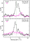 |
Fig. 2. SiO (magenta) and CH3OH (black) spectra extracted at the blueshifted and redshifted peaks of CH3OH (offset with respect to the map phase centre are in the upper right corner). The green dashed vertical line marks the vsys (∼6.8 km s−1Choi 2001). The 3σ level is reported in black (CH3OH) and magenta (SiO) dashed horizontal lines. |
In summary, the observed emission arises from three zones: (i) a very compact region ( , < 50 au), at ±1.5 km s−1 with respect to vsys, dominated by the hot corino emission and traced mainly by methanol; (ii) an intermediate region (
 , 50–150 au), between 2 and 6 km s−1 with respect to vsys, traced by both SiO and CH3OH, which shows an inverted velocity gradient with respect to the large scale, the origin of which is unclear; and (iii) an extended region (
 , > 150 au), above 7 km s−1 with respect to the vsys, traced by SiO and dominated by the jet or outflow.
4. The origin of the inverse velocity gradient
We now discuss the origin of the intermediate region in the inner  (∼150 au), where SiO and CH3OH show an observed inverse velocity gradient with respect to the large scale, and their observed spatial and spectral shift. At this stage, it is important to highlight the formation mechanisms of these two species: CH3OH is formed on the icy grain mantles via CO hydrogenation (e.g., Watanabe & Kouchi 2002; Rimola et al. 2014) and can be released into the gas phase by either ice-mantle sublimation or by grain-mantle sputtering in mild shocks in star forming regions (e.g., Flower et al. 2010). On the contrary, SiO is formed via the sputtering or shattering of grain cores by strong shocks that release Si into the gas phase where it quickly oxygenates. It is estimated that up to ∼10% of Si or SiO can also be frozen into the grain mantles, and therefore be released by grain mantle sputtering in mild shocks as CH3OH (e.g., Caselli et al. 1997; Schilke et al. 1997; Gusdorf et al. 2008a,b; Guillet et al. 2011). As the two species are aligned along the same position angle (PA), it would be reasonable to assume that they both come from the base of the wind launched from the protostellar disc. However, CH3OH is more compact and could also probe the very inner part of the envelope where it is released by thermal evaporation. We investigate the following three possibilities:
Rotating disc or inner envelope. The blueshifted and redshifted emission of CH3OH might indicate rotation in a disc-like structure and/or in the inner envelope, where the ice sublimation dominates the chemistry. However, (i) the PA (∼ − 30°) of the velocity gradient differs by ∼30° from the perpendicular direction of the jet or outflow direction at large scale (above 300 au), as expected for disc emission. Indeed, the jet or outflow direction is estimated to have a PA of 25° −30° (see Fig. A.1, and Choi 2005; Santangelo et al. 2015; De Simone et al. 2020b; Chahine et al. 2024). (ii) Also, the present spatial resolution (∼50 au) is insufficient to assess whether the signature of a rotating or infalling envelope is present in CH3OH and/or SiO (see Fig. D.2 in appendix); and (iii) CH3OH and SiO are aligned on the same PA, and both trace the inverted velocity gradient, but only CH3OH is a known disc tracer.
Indeed, while methanol emission can be explained by ice sublimation, explaining the presence of SiO is not as straightforward. At the methanol emission site (extending out to 90 au,  , and peaking at 45 au,
  , from the protostar) the dust temperature is 65–90 K, which is comparable to the temperature of CH3OH sublimation (60–130 K; see computations in Appendix C). On the other hand, SiO is usually associated with jet activity, i.e., where Si is released by grain sputtering in shocks or entrained in a wind originated inside the dust sublimation radius (e.g., Cabrit et al. 2007; Gusdorf et al. 2008b; Konigl & Pudritz 2000; Tabone et al. 2020; López-Vázquez et al. 2024). Even if 10% of the SiO is trapped in the ice mantles (e.g., Gusdorf et al. 2008a,b; Guillet et al. 2011), it is not clear whether this would be released with the ice once sublimated due to SiO reactivity with water or due to other processes (see details in Appendix C). Alternatively, the two species could be released by grain mantle sputtering at the infalling envelope–disc interface, where slow shocks (< 5–10 km s−1) occur (e.g., Sakai et al. 2014). However, it is unclear whether or not these slow shocks can sputter a sufficient amount of SiO; and if they could, then we have insufficient evidence to decipher whether or not the emission would follow the disc kinematics (see above). In summary, the observed methanol emission could be the result of ice mantle sublimation in the inner rotating envelope or disc, while a fast shock (> 10 km s−1) needs to occur to sputter the dust grains so as to explain the observed SiO abundance.
Jet or outflow precessing and/or on the plane of the sky. Another possibility is that CH3OH and SiO have a non-thermal origin linked to shocks along the jet. The inclination of the IRAS 4A2 jet is still highly uncertain (45°–88° Yıldız et al. 2012; Choi 2005; Marvel et al. 2008; Koumpia et al. 2016). If it were close to the plane of the sky, we would expect to observe blueshifted and redshifted emission in both lobes and along the entire length of the jet, not only in the inner 300 au (see e.g., Cabrit & Bertout 1990; Podio et al. 2021). On the other hand, if the jet precesses and crosses the plane of the sky, it may create a knot with opposite velocity to previous ejection events. However, if this were the case, we would expect to see an alternation of blueshifted and redshifted emission with a periodic pattern and also at larger scales. Moreover, this scenario has been excluded by Chuang et al. (2021) based on a 3D precession model. Indeed, this could explain the S-shaped structure of the IRAS 4A outflows traced in SO at large scale, but not the inversion of the velocity gradient at small scales.
Wide-angle wind. Figure 3 shows a simplistic sketch that summarises our interpretation of the observed spatial and kinematical distribution. The sketch shows the base of a wide and inclined disc wind that crosses the plane of the sky and shows an inversion in velocity at 300 au with respect to the large-scale jet or outflow. The disc wind is plausibly magnetically driven and is expected to reach the maximum radius at the Alfvén surface and to recollimate beyond that (Tabone et al. 2020). The prototypical disc wind in HH212 has been detected at heights of below ∼200 au (Frank et al. 2014; Tabone et al. 2017; Lee et al. 2021a; Nazari et al. 2024), which is consistent with our findings. Given the covered velocity ranges between 2 and 6 km s−1, the inclination of the gas crossing the plane of the sky has to be > 55° with respect to the line of sight. This is required in order to have a reasonable flow velocity (> 10 km s−1) to sputter grain mantles and cores so as to release both CH3OH and SiO (see Appendix C).
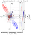 |
Fig. 3. Simplistic sketch (not to scale) of the proposed scenario: The large scale jet is relatively highly inclined (60° in the example here), and has a wide outflowing shocking gas that crosses the plane of the sky. The redshifted and blueshifted emission is represented in red and blue, respectively. The grey-shaded box highlights the view of the projected emission on the plane of the sky that we see in observations. |
Among the three scenarios, we favour the last one as it explains the inverse velocity gradient, the spatial alignment between SiO and CH3OH, and also the observed SiO and CH3OH spectra (where the emission close to vsys is hot-corino dominated and beyond 7 km s−1 is jet or outflow dominated). For the first time, we detect and identify a disc-wind candidate toward the IRAS 4A Class 0 protostar traced in SiO and CH3OH. This increases the number of disc-wind tracers, complementing the typical SO (e.g., Tabone et al. 2017; Codella et al. 2018) and supporting the recently discovered CH3OH (Nazari et al. 2024), and provides important constraints (velocity, inclination, and opening angle) for disc wind theories. It is important to note that the emission of SiO can also be a result of the interaction of the jet with the disc wind giving rise to an unresolved shocked shell (see e.g., Lee et al. 2022b), or a disc-wind rotation (e.g., Lee et al. 2022b). In this way, SiO can be considered as an indirect tracer. However, to explain the observed low velocities, the jet or wind inclination needs to be relatively high (above 80° with respect to the line of sight; see Appendix C). Anyways, observations down to at least 10 au would be needed to test this scenario.
5. Conclusions
This Letter presents FAUST observations of IRAS 4A2 with a resolution of 50 au, as mapped in SiO and CH3OH. The high spatial and spectral resolution observations of FAUST prove to be crucial to studying the interplay between the disc, the envelope, and the outflowing gas. The unique combination of kinematics and chemistry allows us to disentangle the emission at very small scales (50 au) using the chemical formation pathway of each species to retrieve the physical mechanisms at play. The emission below 300 au arises from three zones: (i) a very compact region ( , 50 au), at ±1.5 km s−1 with respect to vsys, dominated by the ice mantle sublimation zone and traced by methanol; (ii) an intermediate region (
 , 50–150 au), between 2 and 6 km s−1 with respect to vsys, traced by both SiO and CH3OH, which shows an inverted velocity gradient with respect to the large scale, and is of unknown origin; and (iii) an extended region (
 , 150 au), above 7 km s−1 with respect to vsys, traced by SiO and dominated by the outflow. We propose that CH3OH and SiO in the intermediate region probe the base of a rotating wide-angle disc wind. The material accelerated in the wind crosses the plane of the sky, giving rise to the observed inverted velocity gradient, and sputters the grains, leading to the release of both species. For the first time, we observe the IRAS 4A disc wind traced by SiO and CH3OH, new tracers beyond the known SO. Finally, we emphasise that observations down to 10 au will be essential to revealing the presence and the possible contribution of the unresolved rotating disc.
Fifty AU STudy of the chemistry in the disc/envelope systems of Solar-like protostars; http://faust-alma.riken.jp.
https://help.almascience.org/kb/articles/what-are-the-amplitude-calibration-issues-caused-by-alma-s-normalization-strategy
Please note that assuming 1 Myr timescale, Tsub could be lower by about 10 K.
Please note that these values critically depend on the assumed frozen-SiO sputtering threshold energy (see discussion in De Simone et al. 2022b; Flower & Pineau des Forets 1994)
Acknowledgments
We warmly acknowledge Dr. J. Enrique Romero for the fruitful discussion on the binding energies and the Si, SiO insights, and Dr. F. Bacciotti on disc winds. This project has received funding from the Marie Sklodowska-Curie for the project “Astro-Chemical Origins” (ACO), grant agreement No 811312, and within the European Union’s Horizon 2020 research and innovation program from the European Research Council (ERC) for the projects “The Dawn of Organic Chemistry” (DOC), grant agreement No 741002. Part of the data deconvolution and analysis was performed using the GRICAD infrastructure (https://gricad.univ-grenoble-alpes.fr). ClCo, LP, and GS acknowledge the PRIN-MUR 2020 BEYOND-2p (Astrochemistry beyond the second period elements, Prot. 2020AFB3FX), the project ASI-Astrobiologia 2023 MIGLIORA (Modeling Chemical Complexity, F83C23000800005), the INAF-GO 2023 fundings PROTO-SKA (Exploiting ALMA data to study planet forming discs: preparing the advent of SKA, C13C23000770005), the INAF Mini-Grant 2022 “Chemical Origins” (PI: L. Podio), and INAF-Minigrant 2023 TRIESTE (“TRacing the chemIcal hEritage of our originS: from proTostars to planEts”; PI: G. Sabatini). LP acknowledges financial support under the National Recovery and Resilience Plan (NRRP), Mission 4, Component 2, Investment 1.1, Call for tender No. 104 published on 2.2.2022 by the Italian Ministry of University and Research (MUR), funded by the European Union “NextGenerationEU” Project Title 2022JC2Y93 ChemicalOrigins: linking the fossil composition of the Solar System with the chemistry of protoplanetary disks – CUP J53D23001600006 – Grant Assignment Decree No. 962 adopted on 30.06.2023 by the Italian Ministry of Ministry of University and Research (MUR). DJ is supported by NRC Canada and by an NSERC Discovery Grant. LL acknowledges the support of DGAPA PAPIIT grants IN108324 and IN112820 and CONACyT-CF grant 263356”. MB acknowledges support from the European Research Council (ERC) Advanced Grant MOPPEX 833460. NC acknowledges funding from the European Research Council (ERC) under the European Union Horizon Europe research and innovation program (grant agreement No. 101042275, project Stellar-MADE). This paper makes use of the following ALMA data: ADS/JAO.ALMA#2018.1.01205.L (PI: S. Yamamoto). ALMA is a partnership of the ESO (representing its member states), the NSF (USA) and NINS (Japan), together with the NRC (Canada) and the NSC and ASIAA (Taiwan), in cooperation with the Republic of Chile. The Joint ALMA Observatory is operated by the ESO, the AUI/NRAO, and the NAOJ.
References
- Andre, P., Ward-Thompson, D., & Barsony, M. 2000, From Prestellar Cores to Protostars: the Initial Conditions of Star Formation (Tucson: University of Arizona Press), 59 [Google Scholar]
- Arce, H. G., Shepherd, D.,Gueth, F., et al. 2007, in Protostars and Planets V, eds. B. Reipurth, D. Jewitt, & K. Keil, 245 [Google Scholar]
- Belloche, A., Maury, A. J., Maret, S., et al. 2020, A&A, 635, A198 [NASA ADS] [CrossRef] [EDP Sciences] [Google Scholar]
- Bianchi, E., López-Sepulcre, A., Ceccarelli, C., et al. 2023, Faraday Discuss., 245, 164 [NASA ADS] [CrossRef] [Google Scholar]
- Blandford, R. D., & Payne, D. G. 1982, MNRAS, 199, 883 [CrossRef] [Google Scholar]
- Bouvier, M., Ceccarelli, C., López-Sepulcre, A., et al. 2022, ApJ, 929, 10 [NASA ADS] [CrossRef] [Google Scholar]
- Bovolenta, G., Bovino, S., Vöhringer-Martinez, E., et al. 2020, Mol. Astrophys., 21, 100095 [NASA ADS] [CrossRef] [Google Scholar]
- Cabrit, S., & Bertout, C. 1990, ApJ, 348, 530 [CrossRef] [Google Scholar]
- Cabrit, S., Codella, C., Gueth, F., et al. 2007, A&A, 468, L29 [NASA ADS] [CrossRef] [EDP Sciences] [Google Scholar]
- Caselli, P., Hartquist, T. W., & Havnes, O. 1997, A&A, 322, 296 [NASA ADS] [Google Scholar]
- Ceccarelli, C. 2004, ASP Conf. Ser., 323, 195 [Google Scholar]
- Ceccarelli, C., Castets, A., Caux, E., et al. 2000, A&A, 355, 1129 [NASA ADS] [Google Scholar]
- Ceccarelli, C., Caselli, P., Fontani, F., et al. 2017, ApJ, 850, 176 [NASA ADS] [CrossRef] [Google Scholar]
- Ceccarelli, C., Viti, S., Balucani, N., & Taquet, V. 2018, MNRAS, 476, 1371 [CrossRef] [Google Scholar]
- Ceccarelli, C., Codella, C., Balucani, N., et al. 2023, in Protostars and Planets VII, eds. S. Inutsuka, Y. Aikawa, T. Muto, K. Tomida, & M. Tamura, ASP Conf. Ser., 534, 379 [NASA ADS] [Google Scholar]
- Chahine, C., Ceccarelli, C., De Simone, M., et al. 2024, MNRAS, submitted [Google Scholar]
- Ching, T.-C., Lai, S.-P., Zhang, Q., et al. 2016, ApJ, 819, 159 [NASA ADS] [CrossRef] [Google Scholar]
- Choi, M. 2001, ApJ, 553, 219 [NASA ADS] [CrossRef] [Google Scholar]
- Choi, M. 2005, ApJ, 630, 976 [CrossRef] [Google Scholar]
- Choi, M., Kang, M., Tatematsu, K., Lee, J.-E., & Park, G. 2011, Publ. Astron. Soc. Japan, 63, 1281 [Google Scholar]
- Chuang, C.-Y., Aso, Y., Hirano, N., Hirano, S., & Machida, M. N. 2021, ApJ, 916, 82 [NASA ADS] [CrossRef] [Google Scholar]
- Codella, C., Bianchi, E., Tabone, B., et al. 2018, A&A, 617, A10 [NASA ADS] [CrossRef] [EDP Sciences] [Google Scholar]
- Codella, C., Ceccarelli, C., Chandler, C., et al. 2021, Front. Astron. Space Sci., 8, 227 [NASA ADS] [CrossRef] [Google Scholar]
- De Simone, M., Codella, C., Testi, L., et al. 2017, A&A, 599, A121 [NASA ADS] [CrossRef] [EDP Sciences] [Google Scholar]
- De Simone, M., Ceccarelli, C., Codella, C., et al. 2020a, ApJ, 896, L3 [NASA ADS] [CrossRef] [Google Scholar]
- De Simone, M., Codella, C., Ceccarelli, C., et al. 2020b, A&A, 640, A75 [NASA ADS] [CrossRef] [EDP Sciences] [Google Scholar]
- De Simone, M., Ceccarelli, C., Codella, C., et al. 2022a, ApJ, 935, L14 [CrossRef] [Google Scholar]
- De Simone, M., Codella, C., Ceccarelli, C., et al. 2022b, MNRAS, 512, 5214 [CrossRef] [Google Scholar]
- de Valon, A., Dougados, C., Cabrit, S., et al. 2020, A&A, 634, L12 [NASA ADS] [CrossRef] [EDP Sciences] [Google Scholar]
- Ferrero, S., Grieco, F., Ibrahim Mohamed, A. S., et al. 2022, MNRAS, 516, 2586 [CrossRef] [Google Scholar]
- Ferrero, S., Zamirri, L., Ceccarelli, C., et al. 2020, ApJ, 904, 11 [NASA ADS] [CrossRef] [Google Scholar]
- Flower, D. R., & Pineau des Forets, G. 1994, MNRAS, 268, 724 [NASA ADS] [CrossRef] [Google Scholar]
- Flower, D. R., Pineau des Forêts, G., & Rabli, D. 2010, MNRAS, 409, 29 [NASA ADS] [CrossRef] [Google Scholar]
- Frank, A., Ray, T. P., Cabrit, S., et al. 2014, in Protostars and Planets VI, eds. H. Beuther, R. S. Klessen, C. P. Dullemond, & T. Henning, 451 [Google Scholar]
- Galametz, M., Maury, A. J., Valdivia, V., et al. 2019, A&A, 632, A5 [NASA ADS] [CrossRef] [EDP Sciences] [Google Scholar]
- Guillet, V., Pineau des Forêts, G., & Jones, A. P. 2011, A&A, 527, A123 [NASA ADS] [CrossRef] [EDP Sciences] [Google Scholar]
- Gusdorf, A., Cabrit, S., Flower, D. R., & Pineau Des Forêts, G. 2008a, A&A, 482, 809 [NASA ADS] [CrossRef] [EDP Sciences] [Google Scholar]
- Gusdorf, A., Pineau des Forêts, G., Cabrit, S., & Flower, D. R. 2008b, A&A, 490, 695 [NASA ADS] [CrossRef] [EDP Sciences] [Google Scholar]
- Hasegawa, T. I., & Herbst, E. 1993, MNRAS, 261, 83 [NASA ADS] [CrossRef] [Google Scholar]
- Herbst, E., & Van Dishoeck, E. 2009, ARA&A, 47, 427 [NASA ADS] [CrossRef] [Google Scholar]
- Jiménez-Serra, I., Caselli, P., Martín-Pintado, J., & Hartquist, T. W. 2008, A&A, 482, 549 [NASA ADS] [CrossRef] [EDP Sciences] [Google Scholar]
- Karska, A., Herczeg, G. J., van Dishoeck, E. F., et al. 2013, A&A, 552, A141 [NASA ADS] [CrossRef] [EDP Sciences] [Google Scholar]
- Ko, C.-L., Liu, H. B., Lai, S.-P., et al. 2020, ApJ, 889, 172 [NASA ADS] [CrossRef] [Google Scholar]
- Konigl, A., & Pudritz, R. E. 2000, Protostars and Planets IV, eds. V. Mannings, A. P. Boss, S. S. Russell (Tucson: University of Arizona Press) 759 [Google Scholar]
- Koumpia, E., van der Tak, F. F. S., Kwon, W., et al. 2016, A&A, 595, A51 [NASA ADS] [CrossRef] [EDP Sciences] [Google Scholar]
- Kristensen, L. E., van Dishoeck, E. F., Bergin, E. A., et al. 2012, A&A, 542, A8 [NASA ADS] [CrossRef] [EDP Sciences] [Google Scholar]
- Lee, C.-F., Tabone, B., Cabrit, S., et al. 2021a, ApJ, 907, L41 [NASA ADS] [CrossRef] [Google Scholar]
- Lee, Y.-H., Johnstone, D., Lee, J.-E., et al. 2021b, ApJ, 920, 119 [NASA ADS] [CrossRef] [Google Scholar]
- Lee, C.-F., Codella, C., Ceccarelli, C., & López-Sepulcre, A. 2022a, ApJ, 937, 10 [NASA ADS] [CrossRef] [Google Scholar]
- Lee, C.-F., Li, Z.-Y., Shang, H., & Hirano, N. 2022b, ApJ, 927, L27 [NASA ADS] [CrossRef] [Google Scholar]
- Lefloch, B., Castets, A., Cernicharo, J., & Loinard, L. 1998, ApJ, 504, L109 [NASA ADS] [CrossRef] [Google Scholar]
- Lesaffre, P., Pineau des Forêts, G., Godard, B., et al. 2013, A&A, 550, A106 [NASA ADS] [CrossRef] [EDP Sciences] [Google Scholar]
- Li, J. I.-H., Liu, H. B., Hasegawa, Y., & Hirano, N. 2017, ApJ, 840, 72 [NASA ADS] [CrossRef] [Google Scholar]
- Lodders, K. 2019, arXiv e-prints [arXiv:1912.00844] [Google Scholar]
- Looney, L. W., Mundy, L. G., & Welch, W. J. 2000, ApJ, 529, 477 [NASA ADS] [CrossRef] [Google Scholar]
- López-Sepulcre, A., Sakai, N., Neri, R., et al. 2017, A&A, 606, A121 [NASA ADS] [CrossRef] [EDP Sciences] [Google Scholar]
- López-Vázquez, J. A., Lee, C.-F., Fernández-López, M., et al. 2024, ApJ, 962, 28 [CrossRef] [Google Scholar]
- Louvet, F., Dougados, C., Cabrit, S., et al. 2018, A&A, 618, A120 [NASA ADS] [CrossRef] [EDP Sciences] [Google Scholar]
- Mairs, S., Lee, S., Johnstone, D., et al. 2024, ApJ, 966, 215 [NASA ADS] [CrossRef] [Google Scholar]
- Marvel, K. B., Wilking, B. A., Claussen, M. J., & Wootten, A. 2008, ApJ, 685, 285 [CrossRef] [Google Scholar]
- Maureira, M. J., Gong, M., Pineda, J. E., et al. 2022, ApJ, 941, L23 [NASA ADS] [CrossRef] [Google Scholar]
- Maury, A. J., André, P., Testi, L., et al. 2019, A&A, 621, A76 [NASA ADS] [CrossRef] [EDP Sciences] [Google Scholar]
- Minissale, M., Aikawa, Y., Bergin, E., et al. 2022, ACS Earth Space Chem., 6, 597 [NASA ADS] [CrossRef] [Google Scholar]
- Müller, H. S. P., Schlöder, F., Stutzki, J., & Winnewisser, G. 2005, J. Mol. Struct., 742, 215 [Google Scholar]
- Müller, H. S. P., Spezzano, S., Bizzocchi, L., et al. 2013, J. Phys. Chem. A, 117, 13843 [Google Scholar]
- Nazari, P., Tabone, B., Ahmadi, A., et al. 2024, A&A, in press, https://doi.org/10.1051/0004-6361/202348676 [Google Scholar]
- Nguyen-Lu’o’ng, Q., Motte, F., Carlhoff, P., et al. 2013, ApJ, 775, 88 [CrossRef] [Google Scholar]
- Okoda, Y., Oya, Y., Imai, M., et al. 2022, ApJ, 935, 136 [CrossRef] [Google Scholar]
- Pascucci, I., Cabrit, S., Edwards, S., et al. 2023, in Protostars and Planets VII, eds. S. Inutsuka, Y. Aikawa, T. Muto, K. Tomida, & M. Tamura, ASP Conf. Ser., 534, 567 [NASA ADS] [Google Scholar]
- Podio, L., Tabone, B., Codella, C., et al. 2021, A&A, 648, A45 [NASA ADS] [CrossRef] [EDP Sciences] [Google Scholar]
- Ray, T., Dougados, C., Bacciotti, F., Eislöffel, J., & Chrysostomou, A. 2007, in Protostars and Planets V, eds. B. Reipurth, D. Jewitt, & K. Keil, 231 [Google Scholar]
- Rimola, A., Taquet, V., Ugliengo, P., Balucani, N., & Ceccarelli, C. 2014, A&A, 572, A70 [NASA ADS] [CrossRef] [EDP Sciences] [Google Scholar]
- Sakai, N., Oya, Y., Sakai, T., et al. 2014, ApJ, 791, L38 [Google Scholar]
- Santangelo, G., Codella, C., Cabrit, S., et al. 2015, A&A, 584, A126 [CrossRef] [EDP Sciences] [Google Scholar]
- Schilke, P., Walmsley, C. M., Pineau Forets, G., & Flower, D. R. 1997, A&A, 321, 293 [Google Scholar]
- Shang, H., Li, Z. Y., & Hirano, N. 2007, in Protostars and Planets V, eds. B. Reipurth, D. Jewitt, & K. Keil, 261 [Google Scholar]
- Shu, F. H., Adams, F. C., & Lizano, S. 1987, ARA&A, 25, 23 [Google Scholar]
- Shu, F., Najita, J., Ostriker, E., et al. 1994, ApJ, 429, 781 [Google Scholar]
- Tabone, B., Cabrit, S., Bianchi, E., et al. 2017, A&A, 607, L6 [NASA ADS] [CrossRef] [EDP Sciences] [Google Scholar]
- Tabone, B., Cabrit, S., Pineau des Forêts, G., et al. 2020, A&A, 640, A82 [CrossRef] [EDP Sciences] [Google Scholar]
- Taquet, V., Codella, C., De Simone, M., et al. 2020, A&A, 637, A63 [NASA ADS] [CrossRef] [EDP Sciences] [Google Scholar]
- Tinacci, L., Germain, A., Pantaleone, S., et al. 2022, ACS Earth and Space Chem., 6, 1514 [NASA ADS] [CrossRef] [Google Scholar]
- Tinacci, L., Germain, A., Pantaleone, S., et al. 2023, ApJ, 951, 32 [CrossRef] [Google Scholar]
- Tobin, J. J., Looney, L. W., Li, Z.-Y., et al. 2018, ApJ, 867, 43 [CrossRef] [Google Scholar]
- Tsukamoto, Y., Maury, A., Commercon, B., et al. 2023, ApJ, 534, 317 [Google Scholar]
- Watanabe, N., & Kouchi, A. 2002, ApJ, 571, L173 [Google Scholar]
- Xu, L.-H., Fisher, J., Lees, R. M., et al. 2008, J. Mol. Spectrosc., 251, 305 [NASA ADS] [CrossRef] [Google Scholar]
- Yang, Y.-L., Evans, N. J., I, Smith, A., et al. 2020, ApJ, 891, 61 [CrossRef] [Google Scholar]
- Yıldız, U. A., Kristensen, L. E., van Dishoeck, E. F., et al. 2012, A&A, 542, A86 [NASA ADS] [CrossRef] [EDP Sciences] [Google Scholar]
- Zhang, Y., Higuchi, A. E., Sakai, N., et al. 2018, ApJ, 864, 76 [NASA ADS] [CrossRef] [Google Scholar]
- Zucker, C., Schlafly, E. F., Speagle, J. S., et al. 2018, ApJ, 869, 83 [NASA ADS] [CrossRef] [Google Scholar]
Appendix A: Overview of FAUST SiO at large scale
Figure A.1 shows the large-scale SiO emission of the IRAS 4A system integrated in different velocity ranges. This provides a general overview of the whole range of velocities involved, for the sake of completeness. Please note that the SiO emission goes beyond the spectral window bandwidth, and therefore beyond the upper velocity range value reported in the figure. It is important to note for the present work that the northern part is redshifted and the southern part is blueshifted. The study of the large-scale structure is beyond the scope of this letter and is presented in Chahine et al. (2024).
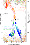 |
Fig. A.1. Large-scale view of the ALMA FAUST SiO emission. Each velocity range corresponds to a specific colour, and is shown in contours starting at 4σ with steps of 2σ, where σ= 3, 3.5, and 6 mJy beam−1 km s−1 for the LV (low-velocity: red and cyan), HV (high-velocity: orange and blue), EHV (extremely high-velocity: pink and green) range, respectively. In background, in grey scale, a range around the vsys is shown (4.9–8.5 km s−1). The synthesised beam is depicted in the lower left corner, and the primary beam is shown as a dashed grey circle. |
Appendix B: Channel maps
Figure B.1 and B.2 show the channel maps of SiO and CH3OH, respectively. The channels are binned to 1 km s−1, for the sake of clarity, and zoom onto the inner 300 au of the IRAS 4A2 protostar. The inverted velocity gradient region is present only in the ( − 6, −2) and (2, 6) km s−1 ranges.
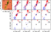 |
Fig. B.1. ALMA FAUST SiO velocity channel maps. Each panel corresponds to a 1 km s−1 increment from the systemic velocity (vsys = 6.8 km s−1; Choi 2001). The black star marks the position of the IRAS 4A2 protostar. The SiO beam is reported in the lower left corner of the vsys panel (shown in colour scale). First contours and steps are 3σ (σ = 1 mJy beam−1). |
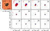 |
Fig. B.2. ALMA FAUST CH3OH velocity channel maps. Each panel corresponds to a 1 km s−1 increment from the systemic velocity (vsys = 6.8 km s−1; Choi 2001). The black star marks the position of the IRAS 4A2 protostar. The CH3OH beam is reported in the lower left corner of the vsys panel (shown in colour scale). First contours and steps are 3σ (σ = 1.1 mJy beam−1). |
Appendix C: SiO and CH3OH: sputtering or sublimation?
C.1. Sublimation:
In order for a species to be desorbed from the ice mantle, the dust needs to reach the species sublimation temperature. Considering species that are not strongly associated to each other (e.g. CH3OH adsorbed on a surface made mostly of water or CO), the first-order solution for the desorption rate (kdes) is:
![Mathematical equation: $$ \begin{aligned} \mathrm k_{des}=\nu _{des}e^{-BE[K]/T} \ , \end{aligned} $$](/articles/aa/full_html/2024/06/aa49949-24/aa49949-24-eq24.gif) (C.1)
(C.1)
where BE is the binding energy (namely, the amount of energy required to remove a species from a surface) in Kelvin, and νdes is the pre-exponential factor, which depends on the species and the surface (Minissale et al. 2022; Ferrero et al. 2022). Even if the BE is given most of the time as a single value, recent experiments and theoretical computations show that, for each species, there can be a distribution of BEs (Ferrero et al. 2020; Bovolenta et al. 2020; Minissale et al. 2022; Tinacci et al. 2022, 2023). This is because BE can change based on the site and orientation of the species with respect to the molecules on the substrate.
To retrieve the sublimation temperature from the desorption rate (i.e. the BE value), we solve Equation C.1, taking the half-life time t1/2 as the characteristic time of the desorption, in first approximation, as (Ceccarelli et al. 2023)
![Mathematical equation: $$ \begin{aligned} \mathrm t_{1/2}=\frac{\ln (2)}{k_{des}}= \frac{\ln (2)}{\nu _{des}e^{-BE[K]/T}} \ . \end{aligned} $$](/articles/aa/full_html/2024/06/aa49949-24/aa49949-24-eq25.gif) (C.2)
(C.2)
Therefore,
![Mathematical equation: $$ \begin{aligned} \mathrm T_{sub}= \frac{BE[K]}{\ln (t_{1/2})+\ln (\nu _{des}/\ln (2))} \ . \end{aligned} $$](/articles/aa/full_html/2024/06/aa49949-24/aa49949-24-eq26.gif) (C.3)
(C.3)
Regarding methanol, theoretical predictions by Ferrero et al. (2020) indicate a BE range of (3770–8618) K, while the pre-exponential factor νdes is 3.2 × 10¹⁷ s−1 (Minissale et al. 2022). The BE given by Minissale et al. (2022) is 6621 K, which is consistent with the range found by Ferrero et al. (2020). Using the CH3OH BE range and νdes stated above, and assuming that the grain mantles have been warmed up for a timescale of ∼104 yr 6, Tsub = 60 − 130 K.
We can now estimate the dust temperature at a certain distance from the protostar. When the dust is optically thin, the dust temperature profile heated by a central source with L⋆ luminosity can be approximated by the following equation (Ceccarelli et al. 2000):
![Mathematical equation: $$ \begin{aligned} \mathrm T_{dust}[K]= 75 K \ \Big (\frac{L_\star }{27 L_\odot }\Big )^{1/4}\Big (\frac{r}{150au}\Big )^{-1/2} \ . \end{aligned} $$](/articles/aa/full_html/2024/06/aa49949-24/aa49949-24-eq27.gif) (C.4)
(C.4)
The bolometric luminosity (Lbol ) of IRAS 4A1 and IRAS 4A2 is not measured singularly due to the lack of angular resolution observations at infrared wavelengths. The total bolometric luminosity of the IRAS 4A1+4A2 system is estimated to be 9 L⊙ (Kristensen et al. 2012; Karska et al. 2013). The blueshifted and redshifted emission peaks of methanol are separated by about  (about 45 au) and their emission extends up to 0
 away (about 80 au). If we consider for 4A2 a conservative bolometric luminosity of 4.5 L⊙ (half of the total luminosity), the temperature at 80 au from the protostars is about 65 K, while at 45 au this value is about 90 K.
Regarding SiO, it may be possible to investigate whether or not sublimation could play a role, given that it is thought that about 10% of SiO could already be formed and locked into the ice mantles of the dust grains (see e.g. Gusdorf et al. 2008a,b; Guillet et al. 2011). The binding energy of SiO is reported to be about 3500 K (Hasegawa & Herbst 1993), which translates into a sublimation temperature of about 50 K. Therefore, in theory, at  (60 au) away from the protostar (at SiO emission peak), the dust temperature could be sufficient to sublimate SiO. If we consider the computed CH3OH/SiO column density ratio (see Table 1), we find that the abundances of SiO should be two orders of magnitude lower than methanol. In IRAS 4A2, De Simone et al. (2020a) estimated a gas density of about 2 × 106 cm−3 in the inner
  . Using this gas density, the abundances should be about 10−6 for CH3OH and 10−8 for SiO (similar to the typical values in shocked regions; e.g. Cabrit et al. 2007; Gusdorf et al. 2008b; Taquet et al. 2020). Considering a 10% of elemental silicon frozen into SiO on the mantle, we could have an abundance of frozen SiO or Si on the icy mantle of about 10−7 − 10−8 (see Figure 4 in Ceccarelli et al. 2018; Lodders 2019). This could, in principle, explain the observed abundance. However, SiO and Si could be highly reactive with the water molecules in the ice, preventing the sublimation of pure SiO and Si into the gas phase. New quantum chemical computations are presently ongoing, and are designed (i) to obtain updated values for the SiO binding energy, taking into account orientation and ice morphology (Gelli et al. in prep.), and (ii) to evaluate how reactive the SiO and Si are on interstellar ices (Enrique-Romero et al. private comm.).
C.2. Sputtering:
SiO has been the most known and most studied shock tracer for more than two decades. Several shock models have predicted that the SiO abundance is highly enhanced in high-velocity shocks (above 25 km s−1). Indeed, at these velocities, the silicon is liberated from the refractory cores of the grains thanks to sputtering and/or shattering, and goes into the gas phase where it quickly oxidises (e.g. Flower & Pineau des Forets 1994; Caselli et al. 1997; Schilke et al. 1997). At lower velocities, some species (including Si, directly SiO, and also CH3OH) that were previously frozen onto the grain mantles can still be released into the gas phase by the sputtering of the icy mantle itself (Jiménez-Serra et al. 2008; Gusdorf et al. 2008b; Guillet et al. 2011; Lesaffre et al. 2013; Nguyen-Lu’o’ng et al. 2013). The above models predict that, to liberate Si or SiO from the frozen mantles, a minimum velocity of about 10 km s−1 is needed7.
From our observations, the small-scale inverse velocity component has a velocity range between 2 and 6 km s−1 (see Figure 1, B.1, B.2 ). This represents the line-of-sight velocity component. To retrieve the radial velocity that would be responsible for the sputtering, we need information on the jet or outflow inclination. The IRAS 4A jet inclination is not yet precisely known. Indeed, due to the large extent of the outflows or jets and the high line-of-sight velocities, Yıldız et al. (2012) suggested an inclination of 45 − 60° with respect to the line of sight. On the other hand, Choi (2005), Marvel et al. (2008), and Koumpia et al. (2016) suggested larger inclinations of about 79°, 88°, and 70°, respectively. However, we can give a constraint on the inclination of the emission at this scale (not necessarily of the jet; see discussion in Section 4) based on the minimum velocity needed to have sputtering, so as to explain the presence of both SiO and CH3OH. Considering that the observed line-of-sight velocity is 2, 6 km s−1 with respect to the vsys, and the velocity required for sputtering a reasonable amount of SiO and CH3OH (see above), we need an inclination with respect to the line of sight of above 55° for a radial velocity of 10 km s−1, and above 80° for 35 km s−1.
Appendix D: Position–velocity diagrams
We selected eight regions of  in wide (shown in Figure D.1) where we extract the PV diagrams: one of
  in length passing through the direction identified by the redshifted and blueshifted emission peak of methanol in the inner
  (PA∼30°) and the other seven perpendicular to that, each separated by
  , and of
  length. The PV diagrams extracted from these regions for SiO are shown in Figure D.3, while the one extracted from the parallel slice and the path following the SiO structures (shown in red and white, respectively, in Figure D.1) for both CH3OH and SiO is shown in Figure D.2). We note that, as also visible in the channel maps (Figure B.1), the SiO PV diagram on the path
  9 and
9 and  6 south of IRAS 4A2 are blueshifted while at
  3 south, a redshifted component appears together with the blueshifted ones. In the north paths, the situation is similar with redshifted and blueshifted components inverted. The emission is confined to around
  of the selected axis, and does not show any peculiar structure. Only the emission along the path
  9 south of 4A2 —which corresponds to the cavity seen in the southern outflow (see Figure 1)— is resolved and shows higher velocities with respect to the small-scale structures (below
  ). In Figure D.2, the emission along the slice parallel to CH3OH and SiO PA (red in Figure D.1) of SiO shows a more evident structure. An inversion of the velocity gradient can be seen here, with red emission in the south and blue emission in the north, below
  from 4A2. The knot at
  can be interpreted as the first knot associated with the outflow. Indeed, the left panel of the figure shows the PV diagram extracted from a region that follows the SiO structure in the moment 0 (white line in Figure D.1). Here, two knots are at
  and ∼1″ with 8.5 km s−1 and 12 km s−1, respectively, and indicate knots in the outflow. Comparing SiO and CH3OH in the right panel of Figure D.2, we can see that CH3OH is elongated following the SiO emission with an inverted velocity gradient. However, our analysis here is limited by spatial resolution and therefore cannot reveal any other kinematical structures.
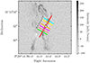 |
Fig. D.1. Regions (coloured) where PV diagrams have been extracted. For reference, the moment 0 of SiO integrated over the whole spectral window is in grey scale. IRAS 4A2 is marked by the white star. |
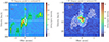 |
Fig. D.2. SiO and CH3OH PV diagrams extracted from different paths. Left: PV Diagram extracted over the path of ∼7″ in length that follows the SiO structures (white in Figure D.1). The SiO emission is shown in colour scale. Green and white contours at (3,5,10) σ are for CH3OH (σ ∼ 2 mJy beam−1) and SiO (σm∼1.6 mJy beam−1), respectively. Right PV diagram extracted over the region of 3″ in length passing through methanol and SiO PA in the inner |

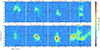 |
Fig. D.3. SiO PV diagrams extracted at the region shown in Figure D.1 and labelled at the top of each plot. The contours are at (3,5,10, 20) σs with σs∼1.5 mJy beam−1. The vertical and horizontal dashed lines represent the vsys (∼6.8 km s−1; Choi 2001), and the 0″ offset (on the 4A2 protostar), respectively. |
All Tables
All Figures
|
Fig. 1. Overview of the SiO and CH3OH emission toward IRAS 4A2 at different scales. Upper left: superposition of the 1.3 mm continuum (grey scale, up to 20% of maximum flux, with contours starting at 15σc with steps of 20σc, where σc = 8 × 10⁻² mJy beam−1) with SiO redshifted and blueshifted emission (salmon and cyan contours, respectively, from 3σ with steps of 4σ, where σ = 2 mJy beam−1 km s−1). Upper right: zoom onto IRAS 4A2. Superposition of the redshifted and blueshifted emission of SiO (salmon and cyan shaded contours) and CH3OH (red and blue contours). Contours start at 3σ with steps of 4σ for SiO and 5σ for CH3OH (σ = 2 mJy beam−1 km s−1). Beams are shown in the lower corners. Lower panels: blueshifted and redshifted emission for SiO and CH3OH shown separately. The beams are shown in the inner corner. In all panels, white and black stars mark the protostars IRAS 4A1 and IRAS 4A2. The redshifted and blueshifted emissions are integrated between +2 and +6 km s−1, and between −6 and −2 km s−1 with respect to the systemic velocity (vsys = +6.8 km s−1; Choi 2001), respectively. The moment 0 between −6 and 6 km s−1 for each species is shown in greyscale. |
| In the text | |
|
Fig. 2. SiO (magenta) and CH3OH (black) spectra extracted at the blueshifted and redshifted peaks of CH3OH (offset with respect to the map phase centre are in the upper right corner). The green dashed vertical line marks the vsys (∼6.8 km s−1Choi 2001). The 3σ level is reported in black (CH3OH) and magenta (SiO) dashed horizontal lines. |
| In the text | |
|
Fig. 3. Simplistic sketch (not to scale) of the proposed scenario: The large scale jet is relatively highly inclined (60° in the example here), and has a wide outflowing shocking gas that crosses the plane of the sky. The redshifted and blueshifted emission is represented in red and blue, respectively. The grey-shaded box highlights the view of the projected emission on the plane of the sky that we see in observations. |
| In the text | |
|
Fig. A.1. Large-scale view of the ALMA FAUST SiO emission. Each velocity range corresponds to a specific colour, and is shown in contours starting at 4σ with steps of 2σ, where σ= 3, 3.5, and 6 mJy beam−1 km s−1 for the LV (low-velocity: red and cyan), HV (high-velocity: orange and blue), EHV (extremely high-velocity: pink and green) range, respectively. In background, in grey scale, a range around the vsys is shown (4.9–8.5 km s−1). The synthesised beam is depicted in the lower left corner, and the primary beam is shown as a dashed grey circle. |
| In the text | |
|
Fig. B.1. ALMA FAUST SiO velocity channel maps. Each panel corresponds to a 1 km s−1 increment from the systemic velocity (vsys = 6.8 km s−1; Choi 2001). The black star marks the position of the IRAS 4A2 protostar. The SiO beam is reported in the lower left corner of the vsys panel (shown in colour scale). First contours and steps are 3σ (σ = 1 mJy beam−1). |
| In the text | |
|
Fig. B.2. ALMA FAUST CH3OH velocity channel maps. Each panel corresponds to a 1 km s−1 increment from the systemic velocity (vsys = 6.8 km s−1; Choi 2001). The black star marks the position of the IRAS 4A2 protostar. The CH3OH beam is reported in the lower left corner of the vsys panel (shown in colour scale). First contours and steps are 3σ (σ = 1.1 mJy beam−1). |
| In the text | |
|
Fig. D.1. Regions (coloured) where PV diagrams have been extracted. For reference, the moment 0 of SiO integrated over the whole spectral window is in grey scale. IRAS 4A2 is marked by the white star. |
| In the text | |
|
Fig. D.2. SiO and CH3OH PV diagrams extracted from different paths. Left: PV Diagram extracted over the path of ∼7″ in length that follows the SiO structures (white in Figure D.1). The SiO emission is shown in colour scale. Green and white contours at (3,5,10) σ are for CH3OH (σ ∼ 2 mJy beam−1) and SiO (σm∼1.6 mJy beam−1), respectively. Right PV diagram extracted over the region of 3″ in length passing through methanol and SiO PA in the inner |
| In the text | |
|
Fig. D.3. SiO PV diagrams extracted at the region shown in Figure D.1 and labelled at the top of each plot. The contours are at (3,5,10, 20) σs with σs∼1.5 mJy beam−1. The vertical and horizontal dashed lines represent the vsys (∼6.8 km s−1; Choi 2001), and the 0″ offset (on the 4A2 protostar), respectively. |
| In the text | |
Current usage metrics show cumulative count of Article Views (full-text article views including HTML views, PDF and ePub downloads, according to the available data) and Abstracts Views on Vision4Press platform.
Data correspond to usage on the plateform after 2015. The current usage metrics is available 48-96 hours after online publication and is updated daily on week days.
Initial download of the metrics may take a while.