| Issue |
A&A
Volume 678, October 2023
|
|
|---|---|---|
| Article Number | A189 | |
| Number of page(s) | 22 | |
| Section | Extragalactic astronomy | |
| DOI | https://doi.org/10.1051/0004-6361/202346738 | |
| Published online | 23 October 2023 | |
Wavelength-resolved reverberation mapping of intermediate-redshift quasars HE 0413-4031 and HE 0435-4312: Dissecting Mg II, optical Fe II, and UV Fe II emission regions⋆
1
Center for Theoretical Physics, Polish Academy of Sciences, Al. Lotników 32/46, 02-668 Warsaw, Poland
e-mail: This email address is being protected from spambots. You need JavaScript enabled to view it.
2
Department of Theoretical Physics and Astrophysics, Faculty of Science, Masaryk University, Kotlářská 2, 611 37 Brno, Czech Republic
3
Laboratório Nacional de Astrofísica, Rua dos Estados Unidos, 154, 37504-364 Itajubá, MG, Brazil
4
National Centre for Nuclear Research, ul. Pasteura 7, 02-093 Warsaw, Poland
5
Astronomical Observatory, University of Warsaw, Al. Ujazdowskie 4, 00-478 Warsaw, Poland
6
Centre for Astrophysics and Cosmology, University of Nova Gorica, Vipavska 11c, 5270 Ajdovščina, Slovenia
7
Astronomical Observatory of the Jagiellonian University, Faculty of Physics, Astronomy and Applied Computer Science, ul. Orla 171, 30-244 Cracow, Poland
8
University of Haifa, Abba Khoushy Ave 199, Haifa 3498838, Israel
9
Instituto de Física y Astronomía, Facultad de Ciencias, Universidad de Valparaíso, Gran Bretaña 1111, Valparaíso, Chile
10
Nicolaus Copernicus Astronomical Center, Polish Academy of Sciences, ul. Bartycka 18, 00-716 Warsaw, Poland
11
School of Physics and Astronomy, Tel Aviv University, Tel Aviv 69978, Israel
12
Copernicus Science Centre, Wybrzeüe Kościuszkowskie 20, 00-390 Warsaw, Poland
13
Astronomisches Institut Ruhr-Universität Bochum, Universitätsstraße 150, 44801 Bochum, Germany
14
Astronomical Institute, Academy of Sciences, Boční II 1401, 14131 Prague, Czech Republic
15
Space Research Center, Polish Academy of Sciences, Bartycka 18A, 00-716 Warszawa, Poland
16
South African Astronomical Observatory, PO Box 9, Observatory, Cape Town 7935, South Africa
17
University of Cape Town, Rondebosch, Cape Town 7700, South Africa
Received:
25
April
2023
Accepted:
13
July
2023
Abstract
Context. We present the wavelength-resolved reverberation mapping (RM) of combined Mg II and UV Fe II broad-line emissions for two intermediate-redshift (z ∼ 1), luminous quasars, HE 0413-4031 and HE 0435-4312, monitored by the Southern African Large Telescope (SALT) and 1m class telescopes between 2012 and 2022.
Aims. Using a wavelength-resolved technique, we aim to disentangle the Mg II and Fe II emission regions and to build a radius–luminosity (R–L) relation for UV Fe II emission, which has so far remained unconstrained.
Methods. We applied several time-delay methodologies to constrain the time delays for total Mg II and Fe II emissions. In addition, wavelength-resolved RM is performed to quantify the inflow or outflow of broad-line region (BLR) gas around the supermassive black hole and to disentangle the emission and the emitting regions based on lines produced in proximity to each other.
Results. The mean total FeII time delay is nearly equal to the mean total MgII time delay for HE 0435-4312, suggesting the co-spatiality of their emission regions. However, in HE 0413-4031, the mean FeII time delay is found to be longer than the mean MgII time delay, suggesting that FeII emission is produced at greater distances from the black hole. The UV FeII R–L relation is updated with these two quasars (now four in total) and compared with the optical FeII relation (20 sources), which suggests that the optical FeII emission region is located further than the UV FeII region by a factor of 1.7–1.9, that is, RFeII-opt ∼ (1.7 − 1.9)RFeII-UV.
Conclusion. Wavelength-resolved reverberation is an efficient way to constrain the geometry and structure of the BLR. We detected a weak pattern in the time delay versus wavelength relation, suggesting that the MgII broad line originates from a region slightly closer to the SMBH than the UV FeII pseudo continuum, although the difference is not very significant. Comparison of MgII, UV, and optical FeII R–L relations suggests that the difference may be greater for lower-luminosity sources, possibly with the MgII emission originating further from the SMBH. In the future, more RM data will be acquired, allowing better constraints on these trends, in particular the UV FeII R–L relation.
Key words: accretion / accretion disks / quasars: emission lines / quasars: individual: HE 0413-4031 / quasars: individual: HE 0435-4312 / techniques: photometric / techniques: spectroscopic
Based on observations made with the Southern African Large Telescope (SALT).
© The Authors 2023
 Open Access article, published by EDP Sciences, under the terms of the Creative Commons Attribution License (https://creativecommons.org/licenses/by/4.0), which permits unrestricted use, distribution, and reproduction in any medium, provided the original work is properly cited.
This article is published in open access under the Subscribe to Open model. This email address is being protected from spambots. You need JavaScript enabled to view it. to support open access publication.
1. Introduction
Reverberation mapping is a powerful technique used to map the inner structure of active galactic nuclei (AGN) based on information on the light travel time between the central disc and the clouds located at the subparsec/parsec scale (see Cackett et al. 2021, for a review). The clouds are predominantly in Keplerian orbits around the supermassive black hole (SMBH) with velocities of the order of ∼1000–10 000 km s. These clouds are the sources of the broad optical and UV emission lines and form the so-called broad-line regions (BLRs). The structure and the formation of these clouds are still debated (see e.g., Krolik 1999; Netzer 2015, for a review). The region is almost unresolved, apart from interferometric measurements for three AGN made with the GRAVITY instrument (3C273, GRAVITY Collaboration 2018; IRAS 09149-6206, GRAVITY Collaboration 2019; and NGC 3783, GRAVITY Collaboration 2020, 2021), which supported the picture of a flattened rotating distribution of BLR clouds.
The reverberation technique provides an indirect measurement of the extent of the BLR and an insight into the kinematics and the geometry of the line-emitting material around the SMBH. The reverberation method was proposed by Blandford & McKee (1982) and Peterson (1993) and requires intense monitoring of the photometric (continuum UV-optical) and spectroscopic (line emission) variations of an AGN. Initially, intense monitoring of many AGN was carried out, mostly concentrating on the Hβ delay measurements (e.g., Kaspi et al. 2000; Peterson et al. 2004; Bentz et al. 2013; Du et al. 2015, 2018; Grier et al. 2017a; Mejía-Restrepo et al. 2018; Fonseca Alvarez et al. 2020; Li et al. 2021; Malik et al. 2023) but recently also intermediate-redshift RM measurements were made of quasars based on the Mg II line (Shen et al. 2016; Lira et al. 2018; Homayouni et al. 2020; Czerny et al. 2019; Zajaček et al. 2020, 2021; Yu et al. 2021; Prince et al. 2022) as well as RM measurements of high-redshift quasars based on the CIV line (Peterson et al. 2005; Kaspi et al. 2007, 2021; Lira et al. 2018; De Rosa et al. 2018; Hoormann et al. 2019; Grier et al. 2019; Shen et al. 2019).
These studies consistently show that, based on the monitoring of a large number of sources, there is a significant correlation between the measured time delay and the monochromatic continuum luminosity –the so-called radius–luminosity (R–L) relation for all three emission lines (Hβ, Mg II, and C IV). The R–L relation enables us to estimate the virial mass of the black hole from single-epoch spectroscopy, following the virial theorem. A more exciting application of the R–L relation is to infer luminosity distances using the measured time delays, from which one can obtain monochromatic luminosities using the R–L relation, and the observed flux densities (Haas et al. 2011; Watson et al. 2011; Czerny et al. 2013). To avoid the circularity problem, one can determine R–L relation parameters and cosmological parameters simultaneously by maximising the likelihood function, which depends on the observed time delays as well as theoretical time delays calculated based on the assumed cosmological model. So far, based on the current samples of RM quasars, it has been shown that the R–L relation parameters are independent of the assumed cosmological model, and therefore the RM quasars are standardisable; however, the cosmological constraints are rather weak in comparison to better-established cosmological probes (Martínez-Aldama et al. 2019; Czerny et al. 2021; Zajaček et al. 2021; Khadka et al. 2021, 2022a; Cao et al. 2022).
From the list of sources that have been monitored by the Southern Large African Telescope (SALT), the reverberation study was performed using the luminous quasars CTS C30.10, HE 0413-4031, and HE 0435-4312 (Czerny et al. 2019; Zajaček et al. 2020, 2021; Prince et al. 2022) using almost 10 years of observations. Wavelength-resolved reverberation is a more advanced technique that allows the wings of the lines to be traced separately from the core as well as the kinematics of the BLR medium when multiple lines contribute to a given wavelength range. Such studies were carried out for more than 35 AGNs by various authors (Kollatschny & Bischoff 2002; Kollatschny 2003; Bentz et al. 2010; Denney et al. 2010; Grier et al. 2012; Du et al. 2018; De Rosa et al. 2018; Xiao et al. 2018; Zhang et al. 2019; Hu et al. 2020b; Vivian et al. 2022), concentrating on low-redshift sources. Obtaining suitable data for bright, more distant quasars requires longer monitoring campaigns and so far only one intermediate-redshift quasar CTS C30.10 has been monitored for 12 years; a wavelength-resolved analysis was presented by Prince et al. (2022). These authors provided the R–L relation for the UV pseudo continuum FeII emission for the first time, using the low-luminosity and the low-redshift AGN NGC 5548 and the intermediate-redshift, luminous quasar CTS C30.10. In the present paper, we extend the previous results by adding a further two intermediate-redshift quasars, HE0413-4031 and HE 0435-4312, each monitored for over 12 years with the Southern Large African Telescope (SALT). Our study is more focused on building the standard R–L relation for UV FeII emission and the comparison with the optical FeII R–L relation.
The paper is organised as follows. In Sect. 2, we provide details about the observational data and the photometric and spectral analyses. In Sect. 3, all the methods applied for the time-delay measurement are introduced, which is followed by results and discussion presented in Sects. 4 and 5, respectively. We summarise the main results in Sect. 6.
2. Observational data
The two quasars, HE 0413-4031 and HE 0435-4312, were discovered in the Hamburg-ESO slitless survey (Wisotzki et al. 2000). These relatively bright quasars, located at intermediate redshift (z ∼ 1), were selected for long-term monitoring with the Southern Large African Telescope (SALT). The time delay of the Mg II line with respect to the continuum has been determined for these two sources, as well as for the third quasar, CTS C30.10 (Czerny et al. 2019; Zajaček et al. 2020, 2021), and the wavelength-resolved delays for CTS C30.10 have been obtained (Prince et al. 2022). The monitoring was extended further with the aim being to perform wavelength-resolved time delays for the other two objects. The basic properties of the two sources are listed in Table 1.
Basic properties of the analysed quasars HE 0413-4031 and HE 0435-4312.
2.1. Spectroscopic monitoring with SALT
The monitoring of the two quasars was done in the years 2012–2022. The spectroscopic measurements were performed with the Robert Stobbie Spectrograph (RSS; Burgh 2003; Kobulnicky et al. 2003; Smith et al. 2006) in a long-slit spectroscopy mode. The same setup was used throughout the campaign for better accuracy of the results. All the observations were made in service mode. We collected 31 spectra for HE 0413-4031 and 28 spectra for HE 0435-4312. We also used the same methodology of data reduction throughout the campaign, as described in more detail in earlier papers (Średzińska et al. 2017; Zajaček et al. 2020, 2021). Every observing block consists of two ∼10 min exposures, and RSS PG1300 grating was always used. The basic reduction of the raw spectra was done with the standard SALT pipeline (Crawford et al. 2010). Subsequently, the spectra were fitted and calibrated using the photometric data for that purpose. Later in the fitting process, the vignetting effect in spectra was corrected using the corresponding calibration stars for each of the objects (see Średzińska et al. 2017), and the spectra were corrected for the Galactic reddening, although the effect is rather small (e.g., HE 0435-4312: AV = 0.045, HE 0413-4031: AV = 0.034).
2.2. Spectral decomposition method
The non-normalised spectra were decomposed assuming the following spectral components: a power law with an arbitrary slope and normalisation, an Mg II line modeled as two separate kinematic components for HE 0435-4312, and a single kinematic component for HE 0413-4031 since the second kinematic component was not required for this source, as argued by Zajaček et al. (2021). Each kinematic component is modelled as a doublet with a doublet ratio of 1.9, and exhibits a Lorentzian shape, and arbitrary normalisation. If two components are present, one of the components is assumed to be at the systematic redshift, and the second one is arbitrarily shifted. If one component is assumed, the arbitrary shift of this component is allowed. We also include Fe II pseudo-continuum emission. This last component was actually assumed to determine the systemic redshift as we were not able to identify any narrow lines that would establish the redshift more reliably.
For the shape of the Fe II line, there are multiple templates available for use, such as Vestergaard & Wilkes (2001), Tsuzuki et al. (2006), and Bruhweiler & Verner (2008). The FeII template derived by Vestergaard & Wilkes (2001) is based on Hubble Space Telescope (HST) spectra of the narrow line Seyfert-1 galaxy whereas Tsuzuki et al. (2006) derived an FeII template by CLOUDY modelling. We adopted one of the recent templates by Bruhweiler & Verner (2008), d12-m20-20-5.dat model, which assumes a cloud number density of 1012 cm−3, a turbulent velocity of 20 km s−1, and a hydrogen ionizing photon flux of 10−20.5 cm−2 s−1 for the quasar HE 0413-4031. The FeII template d11-m20-20.5-735.dat was applied to the quasar HE 0435-4312, corresponding to the lower local density of the cloud of 1011 cm−3. The templates have a fixed shape but arbitrary normalisation. The FeII transition lines identified from the cloudy simulations are shown in Fig. 1 (vertical purple lines), and were broadened by the respective Doppler broadening for both the sources; eventually broad FeII emission lines were obtained, as shown in dotted magenta in Fig. 1. The fits are not very sensitive to the specific choice of template, and we discuss this issue in Appendix D. The template broadening (those are theoretical templates, with no intrinsic broadening) was kept at 2820 km s−1 and 2350 km s−1 for HE 0413-4031 and HE 0435-4312, respectively, in all fits. All the spectral parameters were fitted together. The spectra were fitted only in the narrow wavelength range, between 2700 and 2900 Å, in the rest frame. We show the exemplary data fit for the two quasars in Fig. 2. The fit quality is generally good with the residuals mostly within 1%, although these are somewhat higher at the longest wavelengths for the quasar HE 0413 due to strong skylines in this part of the spectrum, which even after subtraction exhibit residual errors. The kinematic width of Fe II and Mg II from spectral fitting implied that Fe II lines are narrower than the mean total profile of Mg II (4380 km s−1, Zajaček et al. 2020 and 3695 km s−1, Zajaček et al. 2021). We tested the effect of other kinematic widths of the Fe II templates on the fit quality and the results are not very sensitive to the adopted values within a few hundred km s−1 (see Appendix D). This is due to the fact that the number of transitions in the 2700–2900 Å range is quite high (37–61 transitions, depending on the template) and so the component is always very broad. We cannot treat the Fe II width as just another parameter for computational reasons: the Fe II template at each wavelength is calculated as a convolution with a Gaussian, which is time consuming. If the width is kept constant during the fitting process, this convolution is calculated just once, and only the amplitude varies during iterations.
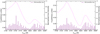 |
Fig. 1. Pseudo-continuum UV FeII emission profile (dotted magenta) obtained by smearing the FeII transition lines (purple) by a velocity profile of 2820 km s−1 for HE 0413-4031 (left panel) and 2350 km s−1 for HE 0435-4312 (right panel). Transition lines are theoretical predictions taken from FeII templates (Bruhweiler & Verner 2008) d12-m20-20-5.dat for HE 0413-4031 and d11-m20-20.5-735.dat for HE 0435-4312. |
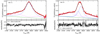 |
Fig. 2. An example of the spectral decomposition of two sources is shown here. Left panel: observation 11 from the SALT telescope (red) for HE 0413-4031 fitted with one component (blue) of MgII, FeII pseudo-continuum (magenta), and the power-law (green) representing the continuum from the accretion disc. The lower panel shows the residuals of the fit. Right panel: observation 10 from the SALT telescope (red) for HE 0435-4312 fitted with two components of MgII (blue) and the rest are the same as the left panel. |
The decomposition of all data sets for the two quasars shows an interesting difference. For HE 0435, the wings of the Mg II line on both sides are well below the Fe II emission contribution. However, for HE 0413, only the left wing of Mg II is strongly dominated by Fe II, while the right wing is comparable to Fe II. This can potentially affect the wavelength-resolved time delays.
Spectral fits allowed us to determine the equivalent widths (EWs) of the Mg II and Fe II UV in each of the spectra. EW(Fe II) was measured only in the 2700–2900 Å band.
2.3. Photometric monitoring
Spectroscopic monitoring was supplemented with photometric monitoring, with the use of a number of instruments. Some of the data (monitoring in the V band) were collected as part of the OGLE-IV survey (Udalski et al. 2015), which used the 1.3 m Warsaw telescope at the Las Campanas Observatory in Chile. In the later period, the quasars were observed with the 40 cm Bochum Monitoring Telescope (BMT), again in the V band. A part of the data, covering the whole campaign, comes from the SALT measurement with the SALTICAM; however the SALTICAM exposure was not always available. Those exposures (usually two to three exposures for 45 s) were done in the g band. Therefore, the data required cross-calibration, as already mentioned in Zajaček et al. (2020, 2021).
In the case of HE 0435-4312, the data obtained by us were supplemented with the old CATALINA data1, which were binned to decrease the statistical error. These data were required for photometric coverage of the start of the spectroscopic campaign. In the case of the other quasars, the photometric coverage was good enough and so we did not need to include the CATALINA in our analysis. The photometric data (V and g bands) of ASAS-SN2 are also used for both sources. The magnitude in the V and g bands is intercalibrated. The light curves are shown in Fig. 3 (upper panel).
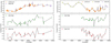 |
Fig. 3. Long-term normalised continuum light curve (top panels) along with total MgII (middle panels) and FeII (bottom panels) line emission light curve. Left panel: HE 0413-4031. Right panel: HE 0435. Total MgII and FeII are in units of 10−16 ergs cm−2 s−1 Å−1. The fluxes from archival CATALINA and ASAS-SN are marked in colour and the continuum represents the observation from SALT+OGLE+BMT. |
2.4. Calibration of the spectra
We then calibrated the spectra using the photometric measurements corresponding to the spectroscopic measurement date; otherwise, they were interpolated through a weighted spline interpolation of first order. To connect the photometric flux density with the modelled non-normalised continuum, we took the V magnitudes reported in Table 1 to get the continuum flux in the observed and rest frames. Then, to obtain the continuum flux at 2800 Å, we used the composite quasar spectrum from Vanden Berk et al. (2001) with a slope of αλ = −1.56. The same procedure was followed in Zajaček et al. (2021). This allowed us to obtain the spectra in physical units as well as to determine the time evolution of the Mg II and Fe II intensity. These findings are presented in Fig. 3. For HE 0435-4312, we also used binned CATALINA data, because the available photometry from SALT+BMT+OGLE did not cover the spectroscopic points. For HE 0413-4031, we did not have this issue and therefore do not include CATALINA data as mentioned earlier.
3. Time-delay measurement methods
As our data are of variable quality, generally heterogenous, and irregularly sampled, we made use of several independent methods to determine the time delays, as was previously done by for example Zajaček et al. (2020, 2021), Rakshit (2020), and Prince et al. (2022). Those methods include the interpolated cross correlation function (ICCF; Gaskell & Peterson 1987; Peterson et al. 1998, 2004), Javelin (Zu et al. 2011), χ2 (Czerny et al. 2013), zDCF (Alexander et al. 1997), and the von Neumann and Bartels estimators of data regularity and randomness (Chelouche et al. 2017).
Interpolated cross-correlation function. Line light curves and the continuum variable emission were cross-correlated to measure the centroid and the peak time delays. We search for the time lag between 200 and 1200 days to focus on the main peak in this range. In addition, for the time delays shorter than 200 days and longer than 1200 days, there are additional time-delay peaks that would skew the time-delay peak distributions and thus enlarge the uncertainties to several hundred days. We report the two time lags from the ICCF, namely the centroid, which is determined for r > 0.8 (τcen), where r is the correlation coefficient, and the peak of the lag distribution, which corresponds to the maximum of the coefficient denoted rmax (τpeak). The peak and centroid distributions were created by simulating the 1000 realisations of line and continuum light curves using the flux-randomisation (FR) and random-subset selection (RSS) methods (see Peterson et al. 1998). The errors of the peak and the centroid time lag are measured by considering the entire distribution and hence the asymmetric error bars are large, of the order of 100 days. Apart from the time-delay measurements and the associated errors, we also provide the time delay corresponding to the maximum value of the ICCF considering the original light curves, rmax, because it informs us directly about the data quality. We also restrict ourselves to r > 0.2, which is generally considered an upper limit for insignificant correlation.
Javelin. We applied the Python version of the Javelin method, whose detailed description can be found in Zu et al. (2011). This latter models the continuum variability as a damped random walk (DRW) process (Kelly et al. 2009; Zu et al. 2013), and the line emission is considered to be a smoothed, scaled, and time-shifted version of the continuum light curve. We searched the time lag between 0 and 2000 days and also performed 1000 bootstrap realisations to estimate the lag distribution. We then calculated the peak of the lag distribution and the errors. For the error estimation, we consider the entire distribution, and hence the error bars are relatively large. Following Zajaček et al. (2021), we also performed the alias mitigation (Grier et al. 2017b) by calculating the light curve pair distribution function, p(τ) = [N(τ)/N(0)]2, where N(τ) is the total number of the continuum-line emission pairs for the time delay τ, and N(0) corresponds to the light-curve pair number for the zero time delay. We show the light-curve pair distribution function for both quasars in Fig. 4, where we also depict the level p(τ) = 0.5, which is reached for time delays longer than 1000 days in the observed frame. On the other hand, the expected time delays for the two quasars marked by dashed vertical lines are above the 0.5 level, which implies that the pair statistics are sufficient in this range. The time-lag distribution constructed from several bootstrap realisations is then weighted by the light-curve pair distribution function p(τ), which results in a lowering of the peaks at long time delays due to a small number of overlapping data points. After applying the alias mitigation, we noticed that for one source it greatly affects the time lags on longer timescales whereas for the second source it does not have a significant effect.
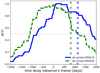 |
Fig. 4. Light-curve pair distribution function p(τ) = [N(τ)/N(0)]2 for the continuum and line-emission light curves of HE0413 (solid blue line) and HE0435 (dashed green line), where N(τ) is the total number of continuum and line-emission data points for the time delay τ (time step is 1 day). Vertical dotted lines stand for the expected time delays in the observer’s frame inferred from the MgII R–L relation; see Fig. 12 for the best-fit relation based on 94 measurements. The values of p(τ) at these time delays are above the 0.5 level for both quasars. |
In addition to the above two methods, we also applied four other, model-independent methods to cross-check the robustness and the consistency of the inferred time lags.
χ2. The χ2 method interpolates the continuum and the line-emission light curves and calculates the χ2 value for a given time lag. For the reverberation mapping measurements, it was applied in Czerny et al. (2013). We considered the time lag range between 0 and 1500 days. The search range is shorter than for the ICCF method because the χ2 method exhibits deep χ2 minima for some of the continuum–line-emission light curve pairs for time delays longer than 1500 days. These would skew the time-delay peak distributions. Based on the comparison with other time-delay methods as well as the light-curve pair distribution p(τ) (see Fig. 4), these minima are not statistically significant and arise due to artifacts and aliases in the light curves. Therefore, we exclude them from the time-delay analysis. The best time lag was subsequently determined from the time-lag peak distribution constructed from 10 000 bootstrap realisations. The uncertainty was determined from the surroundings of the peak value (±50% of the time-lag peak), for which we calculated the asymmetric 1σ uncertainties.
z-transformed discrete correlation function (zDCF). This latter is an improvement on the classical discrete correlation function (DCF; Edelson & Krolik 1988), for which the equal-time binning is replaced by the equal-population binning (Alexander et al. 1997). The final time delay is determined from the maximum-likelihood method, and the uncertainties correspond to 1σ uncertainties determined from 1000 Monte Carlo flux-randomisation realisations.
Von Neumann estimator. Von Neumann estimator belongs to the estimators of data regularity. It estimates the regularity of the continuum and line-emission light curves combined together with a certain time delay τ. The minimum value of the estimator may be considered to represent the best candidate time delay (Chelouche et al. 2017). The final time delay was determined from the peak of the distribution of the von Neumann estimator minima. To obtain the distribution, we generated 1000 light-curve pairs using random subset selection or bootstrap for the wavelength-resolved analysis, while we generated 1500 pairs for the total time-delay analysis. The uncertainties of the time-lag peak were determined in the same way as for the χ2 method.
Bartels estimator. The Bartels estimator is a ranked version of the von Neumann estimator of data regularity (Chelouche et al. 2017). To determine the final time-delay peak and its 1σ uncertainty, we performed 1000 bootstrap realisations of the continuum and the line-emission light curves for the wavelength-resolved analysis, while we generated 1500 light-curve pairs for the total time-delay analysis. Details about these methods and their application to reverberation mapping of intermediate-redshift quasars can be found in Zajaček et al. (2020, 2021).
4. Results
We performed the time-delay analysis for both the total Mg II and Fe II components as well the wavelength-resolved time delays. We did not convert the wavelength to velocity space because our aim, as in Prince et al. (2022), is to analyse the delays of the combination of both the Mg II and the Fe II emission, instead of just analysing the change of the delay along the line profile, as was, for example, performed in Hu et al. (2020b).
4.1. Mg II and Fe II time delay
The continuum and the Mg II and Fe II light curves determined from the normalised SALT data are presented in Fig. 3. All the light curves appear to be of reasonable quality, and the level of variability (Fvar) determined for the SALT observations (2012–2022) of HE 0413-4031 is 11% for the continuum, 15% for the FeII emission, and 6% for the MgII emission. For HE 0435-4312, the variability of MgII, FeII, and the continuum is 12%, 13%, and 6%, respectively. The Fvar estimated for HE 0435-4312 does not include the CATALINA data. The quasar HE 0413-4031 exhibits a long-term variation corresponding to a higher Fvar rather than a short-term variation that is more characteristic of the HE 0435-4312 continuum emission, which shows a relatively low level of variation. The continuum flux density variation of the quasar HE 0413-4031 shows a clear rising trend followed by a slightly decreasing trend, while in the case of the second quasar, the SALT data cover the minimum. The flux variation of the line emission follows the continuum with a time shift and these trends help to establish the time delay relatively well.
We used all the methods mentioned in Sect. 3 to derive the time lags between the continuum and the total Mg II and the Fe II line emissions. For the quasar HE 0435, the measured Mg II time delay depends on the choice of method, but the results are within the range of 489–636 days in the observed frame, corresponding to 220–287 days in the quasar rest frame. The time-delay values for the quasar HE0413 are 654–925 days in the observed frame and 275–389 days in the rest frame. The results for each method are reported in Table 2. The non-weighted average rest-frame time delay of the MgII emission is  days and
  days for HE 0435-4312 and HE 0413-4031, respectively. The uncertainties were inferred by the sum of variances corresponding to the mean-variance determined from all the methods and the standard deviation of the mean value. These are generally consistent with the rest-frame values determined by Zajaček et al. (2021) for the quasar HE 0435-4312
  days) and with those determined by Zajaček et al. (2020) for the quasar HE 0413-4031
  days).
Overview of the time-delay determinations for the total MgII and FeII line emissions.
The FeII line emission time lag was not previously reported because the number of spectroscopic measurements was not high enough to obtain a significant result. Here we report the first UV Fe II time-delay measurements for the quasars HE 0435-4312 and HE 0413-4031. For HE 0435-4312, the time delays lie between 473 and 685 days in the observed frame and between 212 and 308 days in the rest frame. For the other quasar HE 0413-4031, the time delays are slightly higher, between 652 and 957 in the observed frame, and between 274 and 402 days in the rest frame. The total Mg II and Fe II time delays for these two quasars are therefore consistent within uncertainties. We note that the Javelin method applied to both sources yields a longer time delay than those implied by all the other methods. However, the alias mitigation, that is, weighting of time-delay peak distributions by the light-curve pair-number distribution, affects the longer time delay (see figures of Appendix A) for HE 0435-4312, and therefore we report a shorter time delay of about 489 (Mg II) days and 473 (Fe II) days. The pair weighting does not have a significant effect on the other quasar, and therefore has longer Javelin time delays of about 925 and 957 days for Mg II and Fe II line emissions, respectively. As we see in Table 2, the time lag results vary among the methods, though they are generally consistent within the uncertainties. For the total FeII line emission, we obtain the mean rest-frame value of  days and
  days for HE 0435-4312 and HE 0413-4031, respectively.
The mean MgII and FeII time delays are in generally consistent within their respective uncertainties. For HE 0435-4312, the mean value of FeII is larger than the mean MgII time lag by only ∼0.85%. For this quasar, only ICCF (centroid) and the von Neumann and Bartels estimators indicate that the UV FeII emission has a slightly longer time delay with respect to the MgII emission. For HE 0413-4031, the difference between the mean values is larger –the mean FeII time delay is longer than the MgII time delay by ∼5.15%. For this quasar, Javelin, ICCF (centroid and peak), zDCF, and the Bartels estimator support this trend.
4.2. Wavelength-resolved time delays
We follow the approach used by Hu et al. (2020b) in their wavelength-resolved studies, which we also applied previously to analyse the properties of the CTS C30.10 source (Prince et al. 2022). We subtract the continuum component from each spectrum, which leaves the combined contribution of Mg II and FeII pseudo-continuum. Next, we create individual light curves by dividing the studied spectrum in the 2700–2900 Å rest frame range into seven bins, which are not of equal separation in wavelength but are of an equal integral of the RMS spectrum. This is the better choice because it allows a better resolution where the signal-to-noise ratio is higher. We cannot use a greater number of bins because the overall data quality does not allow for denser wavelength sampling. The mean quasar spectrum in the fitted range and the RMS spectrum (observed and model) indicating the spectral ranges are presented in Fig. 5. The vertical blue dashed lines divide the mean and RMS spectra into the different parts used for wavelength-resolved reverberation mapping. The derived light curves corresponding to different parts of the RMS spectrum are shown in Fig. 6 for both the quasars. This division is crucial in order to understand the detailed kinematics, that is, the inflow and the outflow on top of the dominant Keplerian motion of the BLR clouds around the SMBH, where the broad-line emission is produced.
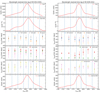 |
Fig. 5. Mean and RMS (model) spectra for the two quasars, with dashed lines indicating the division of the wavelength range. Time delays in the rest frame are plotted in different panels. |
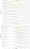 |
Fig. 6. Light curves extracted for the different parts of the RMS spectra. The top panel is for quasar HE 0413-4031 and the bottom one is for HE 0435-4312. |
As the FeII pseudo continuum lies in the two wings of Mg II, the side curves (1, 2, 6, 7) are expected to be dominated by the Fe II emission, while the central curves (3, 4, 5) are dominated by the Mg II emission. Subsequently, we cross-correlate all the curves with the continuum emission to measure the corresponding time delays for each wavelength bin. The recovery of the time delay from all the methods is summarised in Table 3. Below we provide the notes concerning the time-delay results of individual methods.
Time-delay measurements for seven wavelength bins containing a combination of MgII and FeII emission, after subtracting the power-law component.
Javelin. We searched for the time delay between 0 and 1500 days for both quasars. The bootstrap methodology was applied to estimate the mean and peak time delays and the total time-delay peak distribution is used for the error estimation. For HE 0435-4312, the time-delay distributions for all the curves are shown in Fig. A.1, where multiple peaks can be seen in the whole search range. In some of the cases, a prominent peak is observed at a longer time delay of ∼1000 days and in some cases the peak at ∼500 days is dominant. We applied an alias mitigation technique based on the number of overlapping light-curve pairs; it suppressed the longer time-delay peaks where the number of overlapping light-curve pairs is relatively small. In Fig. A.1, the black distribution is the original one and the red distribution corresponds to the one weighted by the distribution of overlapping light-cure pairs. The final time delays for all the curves are found close to 500 days and the exact values with error bars for all the curves are listed in Table 3. However, the alias mitigation has a negligible effect on the time delays of HE 0413-4031 (Fig. A.2), and the peak at ∼1000 days remains dominant. However, we do see a wavelength-dependent time delay in the mean distribution. The exact time delays for all the curves are presented in Table 3.
ICCF. For the ICCF method, the time delays were searched for between 200 and 1200 days in the observer’s frame. The correlation coefficient (r) for all the light curves for both quasars is shown in Fig. 7. For HE 0435-4312, the centroid and the peak time delays are found within the ranges of 535–614 days and 502–620 days in the observed frame, respectively. For the light curves 1, 2, 3, and 7, the correlation coefficient is above 0.5 and for the other curves it is around 0.4, which is considered to be significant (see Fig. 7, right panel). For HE 0413-4031, the centroid and the peak time delays are found within the ranges of 627–784 days and 636–757 days in the observed frame, respectively. The correlation coefficient for all the cases is above or around 0.6. The exact values for time delays with error bars are presented in Table 3.
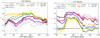 |
Fig. 7. ICCF distribution of all the curves for both the sources are shown here. Left panel: ICCF results for seven light curves of HE 0413-4031 (rainbow-coloured solid lines). The total FeII emission is depicted by a grey dotted line, while the total MgII emission is represented by a grey dashed line. Right panel: same as left panel but for HE 0435-4312. |
χ2method. The distribution of χ2 as a function of the time delay is shown in Fig. 8 for both quasars. For HE 0435-4312, the χ2 distribution exhibits two dips, corresponding to ∼500 days and ∼700 days. In some curves, the dip at ∼500 days is prominent, while for the remaining curves, the dip close to ∼700 dominates. On the other hand, the χ2 distribution in HE 0413-4031 shows a single prominent dip in all cases, although the location of the dips varies from one light curve to another. The time delay range for HE 0435-4312 was found to be between ∼452 and 636 days in the observers’ frame, and for HE 0413-4031, it is between ∼620 and 764 days (see Table 3). The observed time delays inferred using the χ2 method are consistent with ICCF results within the uncertainties.
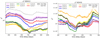 |
Fig. 8. χ2 results for HE 0413-4031 and HE 0435-4312. Left panel: χ2 for seven light curves of HE 0413-4031 (rainbow-coloured solid lines). The total MgII emission is represented by a black solid line, while the total FeII emission is depicted by a grey solid line. Right panel: same as left panel but for HE 0435-4312. |
zDCF. The time delays of all the light curves were searched for between −1000 to 1500 days for both sources. Multiple peaks were detected on both positive and negative sides, but the positive peaks have systematically larger correlation coefficients (see Fig. 9). For HE 0435-4312, the largest correlations are detected at ∼629 days for curves 1, 2, 3, 6, and 7. For light curves 4 and 5, the largest correlation is detected at shorter time delays of the order of 490 days. For HE 0413-4031, multiple peaks were detected on the positive delay side and the most prominent one lies between ∼600 and 700 days. The time delays for curves 1, 2, and 7 have the largest correlation coefficient of 716 days, while curves 3, 4, 5, and 6 have a slightly lower time delay of 654 days in the observer’s frame. The best time delay for each light curve was chosen by inferring the time lag with the maximum likelihood and the corresponding uncertainties are 1σ errors.
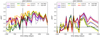 |
Fig. 9. zDCF results for HE 0413-4031 and HE 0435-4312. Left panel: zDCF for seven light curves of HE 0413-4031 (rainbow-coloured solid lines). The total MgII emission is represented by a black dashed line, while the total FeII emission is depicted by a dotted black line. Right panel: same as left panel but for HE 0435-4312. |
Von Neumann and Bartels estimators. We searched for time delays between 0 and 1200 days for both the quasars and the results are shown in Figs. 10 and 11. The best time delays for HE 0435-4312 are found to be between 535 and 615 days for the von-Neumann estimator and between 535 and 715 days for the Bartels estimator. For HE 0413-4031, the observed time delays are between 635 and 815 days and 735 and 845 days for von Neumann and Bartels estimators, respectively. The peak time delays with the uncertainties that correspond to each light curve are listed in Table 3.
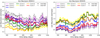 |
Fig. 10. Von Neumann estimator results for HE 0413-4031 and HE 0435-4312. Left panel: temporal evolution of the von Neumann estimator for seven light curves of HE 0413-4031 (rainbow-colored solid lines). The total MgII emission is represented by a black dashed line, while the total FeII emission is depicted by a dotted black line. Right panel: same as left panel but for HE 0435-4312. |
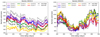 |
Fig. 11. Bartels estimator results for HE 0413-4031 and HE 0435-4312. Left panel: temporal evolution of the Bartels estimator for seven light-curve bins of HE 0413-4031 (rainbow-coloured solid lines). The total MgII emission is represented by a black dashed line, while the total FeII emission is depicted by a dotted black line. Right panel: same for HE 0435-4312. |
5. Discussion
Our monitoring of the two quasars HE0413-4031 and HE0435-4312 over 11 years allows us to report the measurements of the Mg II time delay as well as the UV Fe II time delay. We also obtained wavelength-resolved time delays for the combined Fe II and Mg II overlapping emissions.
The Mg II time delays we report here are consistent with those previously obtained for HE0413-4031 and HE0435-4312 by Zajaček et al. (2020, 2021), respectively. The two measurements are also consistent with other Mg II time delays, predominantly obtained for lower-luminosity sources. Moreover, the two quasars currently belong to the highest-luminosity sources of the MgII sample.
The first MgII R–L relation was presented by Czerny et al. (2013), and this was followed by updated MgII R–L relations for an increasing number of sources (Zajaček et al. 2020, 2021; Martínez-Aldama et al. 2020; Homayouni et al. 2020; Yu et al. 2023). With the gradual increase in the number of sources, the slope decreased from γ ∼ 0.5 to γ ∼ 0.3, and came into tension with the simple photoionisation arguments. At the same time, the scatter significantly increased and is larger than that for the Hβ sample (for discussion see Homayouni et al. 2020). Here, we determine the R–L relation parameters for the currently largest sample of 94 MgII sources (considering our measurements of total Mg II for quasars HE 0413-4031 and HE 0435-4312), whose flux densities and rest-frame time delays are taken from Martínez-Aldama et al. (2020), Zajaček et al. (2021), Yu et al. (2023), and references therein. The correlation between the rest-frame time delay and the monochromatic luminosity at 3000 Å is significant with the Pearson correlation coefficient of r = 0.50 (p = 2.47 × 10⁻⁷) and the Spearman rank-order correlation coefficient of s = 0.36 (p = 3.07 × 10⁻⁴). The MCMC inference of the R–L parameters is presented in Fig. 12, including the likelihood distributions for the slope, the intercept, and the scatter in the left panel and the best-fit MgII R–L relation alongside 94 measurements in the right panel of Fig. 12. The best-fit MgII relation is,
 (1)
(1)
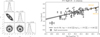 |
Fig. 12. MgII R–L relation parameters (see the corner plot to the left) and comparison of the maximum-likelihood R–L relation with 94 measurements. The scatter of the relation is |

with the intrinsic scatter of  dex. The slope of the MgII R–L relation γ = 0.31 ± 0.06 is significantly shallower than that for the Hβ (Bentz et al. 2013) and MgII R–L relation derived by Homayouni et al. (2020). From the 2D likelihood contours in Fig. 12 (left panel), we can see a degeneracy between the slope and the intercept, that is, within a 3σ confidence interval a steeper slope of γ ∼ 0.40 in combination with the smaller intercept β ∼ 1.70 is possible as well as a very shallow slope of γ ∼ 0.20 in combination with the larger intercept of β ∼ 1.95.
Thus, the Mg II broad-line emission that is well constrained for intermediate-redshift sources forms an R–L relation analogous to the R–L relation for the Hβ line that is well established for low-redshift sources. Such a relation can be used both for the determination of the black hole mass and for cosmological applications. The Mg II measurements (78 QSOs spanning the redshift range 0.0033–1.89 in the sample analysed by Cao et al. 2022) do not yet give strong constraints but imply that the MgII R–L relation is standardisable and the weak cosmological constraints derived from it are consistent with better established cosmological probes (see also Khadka et al. 2021, 2022b).
5.1. BLR kinematics in HE 0413-4031 and HE 0435-4312
The measured delays of the Fe II and the wavelength-resolved time delay studies offer additional insight into the structure of the BLR. The measurement of the integrated Fe II time delay is rather similar to the measured Mg II time delay. The mean Fe II delay (averaged over the methods) for HE 0435 is nearly the same as for Mg II (just ∼0.85% larger), while for HE 0413 the Fe II delay is longer by ∼5.15%. The small time-delay difference implies spatial proximity of the MgII and FeII line-emitting regions. Although it is expected that the generally narrower FeII line should be positioned further from the SMBH than the MgII line-emitting material (Gaskell et al. 2022), the FeII line widths are not constrained well for either of the quasars based on the comparison of different FeII templates and line widths that yield a comparable χ2 statistic in terms of the spectral fitting; see Appendix D.
The decomposition of the spectrum into Mg II and Fe II in the 2700–2900 Å wavelength range is not unique as it depends on the adopted templates. We used theoretical templates of Bruhweiler & Verner (2008), and the quality of the fits appears satisfactory.
Wavelength-resolved measurements of the combined Fe II and Mg II emission do not suffer from this issue but the division of the light curves into seven wavelength bins decreases the data quality. Still, we seem to see a distinct wavy pattern across the wavelength range and it is different for the two sources (see Fig. 5).
For HE 0435-4312, we see a roughly symmetric behaviour, particularly in ICCF, χ2, and zDCF results, with the shortest time delay in curve 4 (see Fig. 5), which is most dominated by Mg II, and a longer time delay of the wings with a strong contribution from Fe II implied by the spectral decomposition (see Fig. 2). In the case of these three methods, the rest-frame time delay at the core of Mg II is ∼225 days while Fe II-dominated wings show a time delay of ∼275 days. This is clearly different from the results for the CTS C30.10 source (Prince et al. 2022) where the UV Fe II delay was shorter and we postulated that the part of the Fe II emitting region more distant from the observer is shielded from view. We therefore conclude that for HE 0435-4312, the viewing angle towards the nucleus and measured from the symmetry axis is smaller, and such shielding does not occur. The new, generalised picture is shown in Fig. 13. For completeness of the AGN picture, we also show the corona as a base of the failed jet, but it does not have any scientific relevance here. We would also like to mention the results from the Javelin (mean and peak), von Neumann, and Bartels estimators. The Javelin peak distribution shows a trend mildly correlated with the ICCF but mean time delays are almost constant. This can happen because the original Javelin delay distribution has multiple peaks of different strength and the mean is taken over the entire delay distribution, leading to a constant time delay across the light curves. The delays of von Neumann and Bartels are mostly consistent with each other except for the wings, but they show a wavy pattern more or less consistent with the results from ICCF.
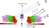 |
Fig. 13. Schematic representation of MgII and FeII emission regions derived from the total time delays in both quasars and comparison with CTS C30.10 (Prince et al. 2022). We also noticed that, in CTS C30.10, the MgII time delay is shorter than the FeII time delay, which suggests a higher inclination of the source, leading to the invisibility of the MgII emission coming from the other side of the black hole. |
In the case of the second quasar, HE 0413-4031, the trend seems to be more complicated, and rather like a wavy pattern, with the shortest time delay in some methods (ICCF, χ2, and Javelin mean) detected for curve 6 (see Fig. 5). Also, there is an asymmetry between the wings. This likely reflects the asymmetry between the wings in the spectral decomposition, because for this quasar, only the blue wing is Fe II-dominated but the red wing has a comparable contribution from both the MgII and the FeII emission. We therefore propose that the difference in the Fe II strength is responsible for the effect and the viewing angle is again small, without any detectable shielding effects. The delays derived from the Javelin mean are consistent with the ICCF and the χ2 methods. The results from the Bartels estimator are rather consistent with the ICCF, showing a shorter time delay for curve 6. The delays derived from the zDCF and von Neumann methods are consistent with each other in the wings but differ for curves 3 and 4.
Further, we tested whether the pattern in wavelength-resolved data is fully explained by the complex contribution of Fe II and Mg II to the spectrum. Following Netzer (2022), we assumed that the delay at a given wavelength should be a mean average of the intrinsic Fe II and Mg II time delays weighted by the relative flux contribution,
 (2)
(2)
where FeIIi and MgIIi are the corresponding integrated flux contribution to the bin i. We fitted this model for the delays obtained from the ICCF centroid method (see Fig. 14). For the quasar HE 0413, the wavy pattern is not fully reproduced. It is likely that there are some kinematic effects that are not included in this simple picture. The mean relative shift of the Fe II and Mg II determined from the spectral fitting (1595 ± 74 km s−1 ) also implies such an effect. The agreement seems much better for the quasar HE 0435.
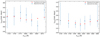 |
Fig. 14. Comparison of observational (ICCF centroid) and theoretical time delay for two quasars (left: HE 0413-4031, right: HE 0435-4312). |
The smaller role of Fe II in the spectrum of HE 0413-4031, that is, by a factor of ∼2, is surprising because this quasar has a considerably higher Eddington ratio and a single-component line profile characteristic of type A quasars (Sulentic et al. 2000). In the optical plane (and in the corresponding UV plane), the Fe II equivalent contribution usually rises with the Eddington ratio (e.g., Panda et al. 2018, 2019a,b). This might be consistent with the findings of no correlation between equivalent widths in the optical and UV bands (Kovačević-Dojčinović & Popović 2015).
5.2. Radius–luminosity relation for the UV Fe II and optical Fe II
The R–L relation offers an important insight into the structure of the BLR. Our new measurements for the delay of the Mg II line complement our previous results as well as those obtained by several other groups (Czerny et al. 2019; Zajaček et al. 2020, 2021; Yu et al. 2023), see also Fig. 12.
However, the R–L relation for Fe II UV emission is new, and it was introduced for the first time in Prince et al. (2022). Here we update this relation by including two more sources studied in this work. The time delays of the total Fe II emissions are taken from Table 2. Combining these two measurements with the Fe II time delay for CTS C30.10 (Prince et al. 2022) as well as with the old IUE measurement of the Fe II UV time delay for NGC 5548 (Maoz et al. 1993), we can now attempt to establish a more reliable R–L relation for the UV Fe II emission. We list these measurements conveniently in Table B.1.
The relation has a typical slope close to 0.5 (see Fig. 15, right panel), which is expected either from the scaling with the ionisation parameter (e.g., Netzer 1990, 2013), or from the dust-based BLR model of Czerny & Hryniewicz (2011). However, in addition to the slope, a vertical shift is important as it informs us about the relative localisation of various emission components of the BLR.
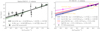 |
Fig. 15. Radius–luminosity relation for the broad FeII complex. Left panel: optical FeII R–L based on 20 measurements (points with error bars; see Table C.1) and the corresponding best-fit relation (black solid line). The best-fit coefficients are in the legend. The intrinsic scatter is σ = 0.27 dex. For comparison, the Hβ RL relation (Bentz et al. 2013) is plotted using a dotted green line. Both the optical FeII and the Hβ RL relations are in agreement with the uncertainties. Right panel: ultraviolet FeII R–L relation based on the four measurements summarised in Table B.1. The black solid line and the blue dashed line represent the best-fit solutions considering two different FeII time delays for CTS C30.10. The UV FeII R–L relation is compared to the optical FeII R–L relation (red solid line), which is rescaled from 5100 Å to 3000 Å using the bolometric corrections of Netzer (2019). A vertical offset between the two R–L relations is apparent, which corresponds to the potential mean size difference between the optical FeII-emitting region and the UV FeII-emitting region of RFeII-opt ∼ (1.7 − 1.9)RFeII-UV, assuming the same slope of γ = 0.5 within the uncertainties. In addition, we also plot the MgII R–L relation based on 94 measurements (dotted magenta line). This relation is flatter than the UV FeII R–L relation and has a larger intercept. However, it is consistent with the MgII time-delay measurements (magenta points) for four UV FeII sources. |
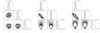 |
Fig. 16. One-dimensional likelihood distributions (along the diagonal) and the two-dimensional likelihood contours for the FeII radius-luminosity relation. Left panel: parameter constraints and the intrinsic scatter σext for the optical FeII radius-luminosity relation based on 20 measurements. Middle panel: parameter constraints and the intrinsic scatter σext for the UV FeII radius-luminosity relation based on 4 measurements (for CTS C30.10 we considered the lower value of the FeII time delay, |


We therefore compared the UV Fe II R–L relation with the optical Fe II R–L relation in order to decompose the emission regions and the photoionisation processes. The Fe II emission in the optical band has been studied for many years (see Gaskell et al. 2022, for a recent review). The optical Fe II time delays of a few nearby sources have been estimated by different groups (Bian et al. 2010; Barth et al. 2013; Chelouche et al. 2014; Hu et al. 2015, 2020b,a). In total, we collected 20 measurements from the literature and summarise them in Table C.1.
The fitted R–L relation for the optical band is shown in Fig. 15 (left panel). The slope is again consistent with 0.5, and the dispersion is typical for the delay measurements in single emission lines. For a better comparison with the UV R–L relation, we converted the 5100 Å–3000 Å UV monochromatic luminosity and plotted the two relations together for better visualisation of the trend (right panel). We clearly see the vertical offset, with UV Fe II being located closer to the SMBH by a factor of ∼1.8. This is not unexpected, because UV lines correspond to larger energies of the atomic transitions. In addition, statistical studies of approximately 300 AGN imply that optical UV Fe II and optical Fe II emissions do not exhibit a simple scaling despite them being kinematically connected (Kovačević-Dojčinović & Popović 2015). According to these later authors, the mean FWHM width of optical Fe II is smaller than UV FeII (2360 km s−1 vs. 2530 km s−1), which would correspond to a separation factor of 1.15. This separation is less than what we found between the two R–L relations (∼1.8). In addition, Kovačević-Dojčinović & Popović (2015) measured a considerable mean outflow velocity in the UV Fe II of 1150 km s−1 with respect to [OIII], implying an inflow of materials. Hu et al. (2008) studied the optical Fe II emission in a large sample of quasars selected from SDSS and show that the red asymmetry in the optical Fe II emission profile could represent an inflow of materials.
In Fig. 15 (right panel), we also plot the MgII R–L relation, which is clearly flatter than both the optical and the UV FeII R–L relations and has a larger intercept. This results in larger MgII time delays than both optical and UV FeII time delays for lower-luminosity sources. At the same time, all three relations appear to converge towards high-luminosity sources, where our three quasars are also located. This behaviour is also observationally confirmed for the low-luminosity source NGC5548, for which the UV FeII time delay is 10 ± 1 days Maoz et al. (1993), while the MgII time delay is constrained to be in the range 34 − 72 days (Clavel et al. 1991). The three luminous quasars – CTS C30.10, HE0413-4031, and HE0435-4312 – have their corresponding MgII and FeII time delays generally very close to each other. For CTS 30.10, several methods indicated that the UV FeII time delay is  days, which is shorter than the MgII time delay of
  (Prince et al. 2022), again consistent with the best-fit MgII and FeII R–L relations.
6. Conclusions
Understanding the BLR kinematics and its geometry is a long-standing problem in AGN physics. The wavelength-resolved reverberation technique has allowed some progress in improving our understanding of the size and structure of the BLR. We present the long-term spectroscopic monitoring of two intermediate-reshift, luminous quasars, HE 0413-4031 and HE 0435-4312, with SALT as well as photometric monitoring with 1m class telescopes. The reverberation mapping of broad Mg II and pseudo-continuum UV Fe II emissions helps us to disentangle their locations.
The Mg II time delays inferred in both the quasars using several methods are consistent within the uncertainties. However, the mean Fe II time delays are slightly higher in both quasars compared to Mg II time delays, suggesting spatially shifted regions of their emission origin. As this is the first time the UV Fe II time delays have been derived for these two quasars, we combined these results with CTS C30.10 to constrain the UV Fe II R–L relation. A subsequent comparison of the optical Fe II and the UV Fe II R–L relations reveals two spatially separated locations with RFeII-opt ∼ (1.7 − 1.9)RFeII-UV.
Acknowledgments
We thank the anonymous referee for their insightful suggestions and comments. The project is based on observations made with the SALT under programs 2012-2-POL-003, 2013-1-POL-RSA-002, 2013-2-POL-RSA-001, 2014-1-POL-RSA-001, 2014-2-SCI-004, 2015-1-SCI-006, 2015-2-SCI-017, 2016-1-SCI-011, 2016-2-SCI-024, 2017-1-SCI-009, 2017-2-SCI-033, 2018-1-MLT-004 (PI: B. Czerny). Polish participation in SALT is funded by grant No. MEiN nr 2021/WK/01. This project has received funding from the European Research Council (ERC) under the European Union’s Horizon 2020 research and innovation program (grant agreement No. [951549]). The project was partially supported by the Polish Funding Agency National Science Centre, project 2017/26/A/ST9/00756 (MAESTRO 9). B.C. and M.Z. acknowledge the OPUS-LAP/GAR-LA bilateral project (2021/43/I/ST9/01352/OPUS 22. M. L. M.-A. acknowledges financial support from Millenium Nucleus NCN19_058 (TITANs). S.K. acknowledges the financial support of the Polish National Science Center through the grant no. 2018/31/B/ST9/00334 (OPUS 16)GF22-04053L). C.S.F. and M.H. acknowledge support from DFG programs HA3555/14-2 and CH71/33-1. G.P. acknowledges the grant of the Polish Ministry of Science and Higher Education (decision number DIR/WK/ 2018/09).
References
- Alexander, T. 1997, Astron. Time Ser., 218, 163 [CrossRef] [Google Scholar]
- Barth, A. J., Pancoast, A., Bennert, V. N., et al. 2013, ApJ, 769, 128 [NASA ADS] [CrossRef] [Google Scholar]
- Bentz, M. C., Horne, K., Barth, A. J., et al. 2010, ApJ, 720, L46 [NASA ADS] [CrossRef] [Google Scholar]
- Bentz, M. C., Denney, K. D., Grier, C. J., et al. 2013, ApJ, 767, 149 [Google Scholar]
- Bian, W.-H., Huang, K., Hu, C., et al. 2010, ApJ, 718, 460 [NASA ADS] [CrossRef] [Google Scholar]
- Blandford, R. D., & McKee, C. F. 1982, ApJ, 255, 419 [Google Scholar]
- Bruhweiler, F., & Verner, E. 2008, ApJ, 675, 83 [NASA ADS] [CrossRef] [Google Scholar]
- Burgh, E. B., Nordsieck, K. H., Kobulnicky, H. A., et al. 2003, SPIE Conf. Ser., 4841, 1463 [NASA ADS] [Google Scholar]
- Cackett, E. M., Bentz, M. C., & Kara, E. 2021, iScience, 24, 102557 [NASA ADS] [CrossRef] [Google Scholar]
- Cao, S., Zajaek, M., Panda, S., et al. 2022, MNRAS, 516, 1721 [NASA ADS] [CrossRef] [Google Scholar]
- Chelouche, D., Rafter, S. E., Cotlier, G. I., Kaspi, S., & Barth, A. J. 2014, ApJ, 783, L34 [CrossRef] [Google Scholar]
- Chelouche, D., Pozo-Nuñez, F., & Zucker, S. 2017, ApJ, 844, 146 [CrossRef] [Google Scholar]
- Clavel, J., Reichert, G. A., Alloin, D., et al. 1991, ApJ, 366, 64 [NASA ADS] [CrossRef] [Google Scholar]
- Crawford, S. M., Still, M., Schellart, P., et al. 2010, SPIE Conf. Ser., 7737, 773725 [Google Scholar]
- Czerny, B., & Hryniewicz, K. 2011, A&A, 525, L8 [NASA ADS] [CrossRef] [EDP Sciences] [Google Scholar]
- Czerny, B., Hryniewicz, K., Maity, I., et al. 2013, A&A, 556, A97 [NASA ADS] [CrossRef] [EDP Sciences] [Google Scholar]
- Czerny, B., Olejak, A., Rałowski, M., et al. 2019, ApJ, 880, 46 [Google Scholar]
- Czerny, B., Martínez-Aldama, M. L., Wojtkowska, G., et al. 2021, Acta Phys. Pol. A, 139, 389 [NASA ADS] [CrossRef] [Google Scholar]
- Denney, K. D., Peterson, B. M., Pogge, R. W., et al. 2010, ApJ, 721, 715 [NASA ADS] [CrossRef] [Google Scholar]
- De Rosa, G., Fausnaugh, M. M., Grier, C. J., et al. 2018, ApJ, 866, 133 [NASA ADS] [CrossRef] [Google Scholar]
- Du, P., Hu, C., Lu, K.-X., et al. 2015, ApJ, 806, 22 [NASA ADS] [CrossRef] [Google Scholar]
- Du, P., Brotherton, M. S., Wang, K., et al. 2018, ApJ, 869, 142 [CrossRef] [Google Scholar]
- Edelson, R. A., & Krolik, J. H. 1988, ApJ, 333, 646 [Google Scholar]
- Fonseca Alvarez, G., Trump, J. R., Homayouni, Y., et al. 2020, ApJ, 899, 73 [CrossRef] [Google Scholar]
- Gaskell, C. M., & Peterson, B. M. 1987, ApJS, 65, 1 [NASA ADS] [CrossRef] [Google Scholar]
- Gaskell, M., Thakur, N., Tian, B., & Saravanan, A. 2022, Astron. Nachr., 343, e210112 [NASA ADS] [CrossRef] [Google Scholar]
- GRAVITY Collaboration (Sturm, E., et al.) 2018, Nature, 563, 657 [Google Scholar]
- GRAVITY Collaboration (Abuter, R., et al.) 2019, The Messenger, 178, 20 [NASA ADS] [Google Scholar]
- GRAVITY Collaboration (Amorim, A., et al.) 2020, A&A, 643, A154 [NASA ADS] [CrossRef] [EDP Sciences] [Google Scholar]
- GRAVITY Collaboration (Amorim, A., et al.) 2021, A&A, 648, A117 [NASA ADS] [CrossRef] [EDP Sciences] [Google Scholar]
- Grier, C. J., Peterson, B. M., Pogge, R. W., et al. 2012, ApJ, 755, 60 [NASA ADS] [CrossRef] [Google Scholar]
- Grier, C. J., Pancoast, A., Barth, A. J., et al. 2017a, ApJ, 849, 146 [NASA ADS] [CrossRef] [Google Scholar]
- Grier, C. J., Trump, J. R., Shen, Y., et al. 2017b, ApJ, 851, 21 [NASA ADS] [CrossRef] [Google Scholar]
- Grier, C. J., Shen, Y., Horne, K., et al. 2019, ApJ, 887, 38 [NASA ADS] [CrossRef] [Google Scholar]
- Haas, M., Chini, R., Ramolla, M., et al. 2011, A&A, 535, A73 [NASA ADS] [CrossRef] [EDP Sciences] [Google Scholar]
- Homayouni, Y., Trump, J. R., Grier, C. J., et al. 2020, ApJ, 901, 55 [Google Scholar]
- Hoormann, J. K., Martini, P., Davis, T. M., et al. 2019, MNRAS, 487, 3650 [NASA ADS] [CrossRef] [Google Scholar]
- Hu, C., Wang, J.-M., Ho, L. C., et al. 2008, ApJ, 687, 78 [Google Scholar]
- Hu, C., Du, P., Lu, K.-X., et al. 2015, ApJ, 804, 138 [Google Scholar]
- Hu, C., Li, Y.-R., Du, P., et al. 2020a, ApJ, 890, 71 [NASA ADS] [CrossRef] [Google Scholar]
- Hu, C., Li, S.-S., Guo, W.-J., et al. 2020b, ApJ, 905, 75 [NASA ADS] [CrossRef] [Google Scholar]
- Kaspi, S., Smith, P. S., Netzer, H., et al. 2000, ApJ, 533, 631 [Google Scholar]
- Kaspi, S., Brandt, W. N., Maoz, D., et al. 2007, ApJ, 659, 997 [NASA ADS] [CrossRef] [Google Scholar]
- Kaspi, S., Brandt, W. N., Maoz, D., et al. 2021, ApJ, 915, 129 [NASA ADS] [CrossRef] [Google Scholar]
- Kelly, B. C., Bechtold, J., & Siemiginowska, A. 2009, ApJ, 698, 895 [Google Scholar]
- Khadka, N., Yu, Z., Zajaček, M., et al. 2021, MNRAS, 508, 4722 [NASA ADS] [CrossRef] [Google Scholar]
- Khadka, N., Martínez-Aldama, M. L., Zajaek, M., Czerny, B., & Ratra, B. 2022a, MNRAS, 513, 1985 [NASA ADS] [CrossRef] [Google Scholar]
- Khadka, N., Zajaček, M., Panda, S., Martínez-Aldama, M. L., & Ratra, B. 2022b, MNRAS, 515, 3729 [NASA ADS] [CrossRef] [Google Scholar]
- Kobulnicky, H. A., Nordsieck, K. H., Burgh, E. B., et al. 2003, SPIE Conf. Ser., 4841, 1634 [NASA ADS] [Google Scholar]
- Kollatschny, W. 2003, A&A, 407, 461 [CrossRef] [EDP Sciences] [Google Scholar]
- Kollatschny, W., & Bischoff, K. 2002, A&A, 386, L19 [NASA ADS] [CrossRef] [EDP Sciences] [Google Scholar]
- Kovačević-Dojčinović, J., & Popović, L. Č. 2015, ApJS, 221, 35 [Google Scholar]
- Krolik, J. H. 1999, Active Galactic Nuclei: From the Central Black Hole to the Galactic Environment (Princeton, N.J: Princeton University Press) [Google Scholar]
- Li, S.-S., Yang, S., Yang, Z.-X., et al. 2021, ApJ, 920, 9 [NASA ADS] [CrossRef] [Google Scholar]
- Lira, P., Kaspi, S., Netzer, H., et al. 2018, ApJ, 865, 56 [NASA ADS] [CrossRef] [Google Scholar]
- Lu, K.-X., Wang, J.-G., Zhang, Z.-X., et al. 2021, ApJ, 918, 50 [NASA ADS] [CrossRef] [Google Scholar]
- Malik, U., Sharp, R., Penton, A., et al. 2023, MNRAS, 520, 2009 [NASA ADS] [CrossRef] [Google Scholar]
- Maoz, D., Netzer, H., Peterson, B. M., et al. 1993, ApJ, 404, 576 [NASA ADS] [CrossRef] [Google Scholar]
- Martínez-Aldama, M. L., Czerny, B., Kawka, D., et al. 2019, ApJ, 883, 170 [CrossRef] [Google Scholar]
- Martínez-Aldama, M. L., Zajaček, M., Czerny, B., & Panda, S. 2020, ApJ, 903, 86 [CrossRef] [Google Scholar]
- Mejía-Restrepo, J. E., Lira, P., Netzer, H., Trakhtenbrot, B., & Capellupo, D. M. 2018, Nat. Astron., 2, 63 [CrossRef] [Google Scholar]
- Netzer, H. 1990, in AGN Emission Lines, eds. T. J.-L. Courvoisier& M. Mayor (Berlin, Heidelberg: Springer Berlin Heidelberg), 57 [Google Scholar]
- Netzer, H. 2013, The Physics and Evolution of Active Galactic Nuclei (Cambridge, UK: Cambridge University Press) [Google Scholar]
- Netzer, H. 2015, ARA&A, 53, 365 [Google Scholar]
- Netzer, H. 2019, MNRAS, 488, 5185 [NASA ADS] [CrossRef] [Google Scholar]
- Netzer, H. 2022, MNRAS, 509, 2637 [NASA ADS] [Google Scholar]
- Panda, S., Czerny, B., Adhikari, T. P., et al. 2018, ApJ, 866, 115 [CrossRef] [Google Scholar]
- Panda, S., Czerny, B., Done, C., & Kubota, A. 2019a, ApJ, 875, 133 [CrossRef] [Google Scholar]
- Panda, S., Marziani, P., & Czerny, B. 2019b, ApJ, 882, 79 [NASA ADS] [CrossRef] [Google Scholar]
- Peterson, B. M. 1993, PASP, 105, 247 [NASA ADS] [CrossRef] [Google Scholar]
- Peterson, B. M., Wanders, I., Horne, K., et al. 1998, PASP, 110, 660 [Google Scholar]
- Peterson, B. M., Ferrarese, L., Gilbert, K. M., et al. 2004, ApJ, 613, 682 [Google Scholar]
- Peterson, B. M., Bentz, M. C., Desroches, L.-B., et al. 2005, ApJ, 632, 799 [NASA ADS] [CrossRef] [Google Scholar]
- Prince, R., Zajaček, M., Czerny, B., et al. 2022, A&A, 667, A42 [NASA ADS] [CrossRef] [EDP Sciences] [Google Scholar]
- Rafter, S. E., Kaspi, S., Chelouche, D., et al. 2013, ApJ, 773, 24 [NASA ADS] [CrossRef] [Google Scholar]
- Rakshit, S. 2020, A&A, 642, A59 [NASA ADS] [CrossRef] [EDP Sciences] [Google Scholar]
- Shen, Y., Horne, K., Grier, C. J., et al. 2016, ApJ, 818, 30 [NASA ADS] [CrossRef] [Google Scholar]
- Shen, Y., Grier, C. J., Horne, K., et al. 2019, ApJ, 883, L14 [NASA ADS] [CrossRef] [Google Scholar]
- Smith, M. P., Nordsieck, K. H., Burgh, E. B., et al. 2006, SPIE Conf. Ser., 6269, 62692A [NASA ADS] [Google Scholar]
- Średzińska, J., Czerny, B., Hryniewicz, K., et al. 2017, A&A, 601, A32 [NASA ADS] [CrossRef] [EDP Sciences] [Google Scholar]
- Sulentic, J. W., Marziani, P., & Dultzin-Hacyan, D. 2000, ARA&A, 38, 521 [Google Scholar]
- Tsuzuki, Y., Kawara, K., Yoshii, Y., et al. 2006, ApJ, 650, 57 [NASA ADS] [CrossRef] [Google Scholar]
- Udalski, A., Szymański, M. K., & Szymański, G. 2015, Acta Astron, 65, 1 [Google Scholar]
- Vanden Berk, D. E., Richards, G. T., Bauer, A., et al. 2001, AJ, 122, 549 [Google Scholar]
- Véron-Cetty, M. P., & Véron, P. 2010, A&A, 518, A10 [Google Scholar]
- Vestergaard, M., & Wilkes, B. J. 2001, ApJS, 134, 1 [Google Scholar]
- Vivian, U., Barth, A. J., Vogler, H. A., et al. 2022, ApJ, 925, 52 [CrossRef] [Google Scholar]
- Watson, D., Denney, K. D., Vestergaard, M., & Davis, T. M. 2011, ApJ, 740, L49 [CrossRef] [Google Scholar]
- Wisotzki, L., Christlieb, N., Bade, N., et al. 2000, A&A, 358, 77 [NASA ADS] [Google Scholar]
- Xiao, M., Du, P., Lu, K.-K., et al. 2018, ApJ, 865, L8 [NASA ADS] [CrossRef] [Google Scholar]
- Yu, Z., Martini, P., Penton, A., et al. 2021, MNRAS, 507, 3771 [NASA ADS] [CrossRef] [Google Scholar]
- Yu, Z., Martini, P., Penton, A., et al. 2023, MNRAS, 522, 4132 [NASA ADS] [CrossRef] [Google Scholar]
- Zajaček, M., Czerny, B., Martinez-Aldama, M. L., et al. 2020, ApJ, 896, 146 [Google Scholar]
- Zajaček, M., Czerny, B., Martinez-Aldama, M. L., et al. 2021, ApJ, 912, 10 [CrossRef] [Google Scholar]
- Zhang, Z.-X., Du, P., Smith, P. S., et al. 2019, ApJ, 876, 49 [NASA ADS] [CrossRef] [Google Scholar]
- Zu, Y., Kochanek, C. S., & Peterson, B. M. 2011, ApJ, 735, 80 [NASA ADS] [CrossRef] [Google Scholar]
- Zu, Y., Kochanek, C. S., Kozłowski, S., & Udalski, A. 2013, ApJ, 765, 106 [NASA ADS] [CrossRef] [Google Scholar]
Appendix A: Alias mitigation
We applied the alias mitigation technique to examine the reliability of longer-time delays frequently seen in Javelin results. The detail of the technique is described in section 3. The Javelin time-delay distribution for both the sources before and after the alias mitigation are shown in Figures A.1 and A.2.
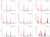 |
Fig. A.1. Javelin bootstrap results from HE 0435 with 1000 realisations for all the seven curves (from left to right) along with total MgII and FeII (last two plots of the lower panel). The peak and results from this are listed in Table 3. We also use the alias mitigation using down-weighting by the overlapping pairs. The black histogram represents the original delay distribution and the red one is after alias mitigation. |
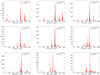 |
Fig. A.2. Javelin bootstrap results from HE 0413 with 1500 realisations for all the seven curves (from left to right) along with total MgII and FeII (last two plots of the lower panel). The peak and results from this are listed in Table 3. We also use the alias mitigation using down-weighting by the overlapping pairs. The black histogram represents the original delay distribution and the red one is after alias mitigation. |
Appendix B: UV FeII sample
Table B.1 provides the list of four sources for which the significant time delay of the UV FeII line complex was measured.
Detailed information about the sources used in the UV FeII R–L relation.
Appendix C: Optical FeII sample
Table C.1 provides the list of 20 sources for which the significant time delay of the optical FeII line complex was measured.
Detailed information about the sources used in the optical FeII R–L relation.
Appendix D: UV Fe II modelling with different templates and equivalent widths
We tested the various templates provided by the Bruhweiler & Verner (2008) to model the UV Fe II emission with a fixed velocity width (km/s). The plots are shown in the left panel of Figure D.1. We note that for the quasar HE 0413-4031, except for BV9 and BV12, all the templates give very similar results. In comparison, for HE 0435-4312, all templates are a good choice. We also tested the choice of templates over various values of the velocity width (km/s), shown in the right panel of Figure D.1. We do not see any significant difference in the fitting. In addition, we also show the corresponding light curves for two templates and two velocity widths for both the quasars and the light curves are shown in Fig D.2 and D.3. For both the quasars, the light curves are in agreement for different templates or for different velocity widths.
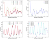 |
Fig. D.1. We show the distribution of chi-square value for different FeII templates and widths. The left panel represents the chi-square distribution of different templates that have been used to model the UV Fe II emission. The right panel shows the chi-square distribution when various velocity widths (km/s) were chosen to model the UV FeII. The upper panel and lower panel are for HE 0413 and HE 0435 sources. The templates name are the following: BV2: d11-5-m20-20-5.dat, BV3: d11-m05-20-5.dat, BV4: d11-m10-20-5.dat, BV5: d11-m20-20.5-735.dat, BV6: d11-m20-20-5.dat, BV7: d11-m20-20.dat, BV8: d11-m20-21-735.dat, BV9: d11-m20-21.dat, BV10: d11-m30-20-5-735.dat, BV11: d11-m30-20-5.dat, BV12: d11-m50-20-5.dat, d11: d11-m20-20-5.dat, d12: d12-m20-20-5.dat. |
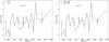 |
Fig. D.2. Total Fe II light curve for HE 0413 produced for the two sets of templates (left panel) and two sets of line widths (right panel). As we argue in the main text, the different templates and different velocity widths do not significantly affect the light curve. |
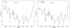 |
Fig. D.3. Total Fe II light curve for HE 0435 produced for the two sets of templates (left panel) and the two sets of velocity widths (right panel). As we argue in the text, the different templates and different velocity widths do not significantly affect the light curve. |
All Tables
Overview of the time-delay determinations for the total MgII and FeII line emissions.
Time-delay measurements for seven wavelength bins containing a combination of MgII and FeII emission, after subtracting the power-law component.
All Figures
|
Fig. 1. Pseudo-continuum UV FeII emission profile (dotted magenta) obtained by smearing the FeII transition lines (purple) by a velocity profile of 2820 km s−1 for HE 0413-4031 (left panel) and 2350 km s−1 for HE 0435-4312 (right panel). Transition lines are theoretical predictions taken from FeII templates (Bruhweiler & Verner 2008) d12-m20-20-5.dat for HE 0413-4031 and d11-m20-20.5-735.dat for HE 0435-4312. |
| In the text | |
|
Fig. 2. An example of the spectral decomposition of two sources is shown here. Left panel: observation 11 from the SALT telescope (red) for HE 0413-4031 fitted with one component (blue) of MgII, FeII pseudo-continuum (magenta), and the power-law (green) representing the continuum from the accretion disc. The lower panel shows the residuals of the fit. Right panel: observation 10 from the SALT telescope (red) for HE 0435-4312 fitted with two components of MgII (blue) and the rest are the same as the left panel. |
| In the text | |
|
Fig. 3. Long-term normalised continuum light curve (top panels) along with total MgII (middle panels) and FeII (bottom panels) line emission light curve. Left panel: HE 0413-4031. Right panel: HE 0435. Total MgII and FeII are in units of 10−16 ergs cm−2 s−1 Å−1. The fluxes from archival CATALINA and ASAS-SN are marked in colour and the continuum represents the observation from SALT+OGLE+BMT. |
| In the text | |
|
Fig. 4. Light-curve pair distribution function p(τ) = [N(τ)/N(0)]2 for the continuum and line-emission light curves of HE0413 (solid blue line) and HE0435 (dashed green line), where N(τ) is the total number of continuum and line-emission data points for the time delay τ (time step is 1 day). Vertical dotted lines stand for the expected time delays in the observer’s frame inferred from the MgII R–L relation; see Fig. 12 for the best-fit relation based on 94 measurements. The values of p(τ) at these time delays are above the 0.5 level for both quasars. |
| In the text | |
|
Fig. 5. Mean and RMS (model) spectra for the two quasars, with dashed lines indicating the division of the wavelength range. Time delays in the rest frame are plotted in different panels. |
| In the text | |
|
Fig. 6. Light curves extracted for the different parts of the RMS spectra. The top panel is for quasar HE 0413-4031 and the bottom one is for HE 0435-4312. |
| In the text | |
|
Fig. 7. ICCF distribution of all the curves for both the sources are shown here. Left panel: ICCF results for seven light curves of HE 0413-4031 (rainbow-coloured solid lines). The total FeII emission is depicted by a grey dotted line, while the total MgII emission is represented by a grey dashed line. Right panel: same as left panel but for HE 0435-4312. |
| In the text | |
|
Fig. 8. χ2 results for HE 0413-4031 and HE 0435-4312. Left panel: χ2 for seven light curves of HE 0413-4031 (rainbow-coloured solid lines). The total MgII emission is represented by a black solid line, while the total FeII emission is depicted by a grey solid line. Right panel: same as left panel but for HE 0435-4312. |
| In the text | |
|
Fig. 9. zDCF results for HE 0413-4031 and HE 0435-4312. Left panel: zDCF for seven light curves of HE 0413-4031 (rainbow-coloured solid lines). The total MgII emission is represented by a black dashed line, while the total FeII emission is depicted by a dotted black line. Right panel: same as left panel but for HE 0435-4312. |
| In the text | |
|
Fig. 10. Von Neumann estimator results for HE 0413-4031 and HE 0435-4312. Left panel: temporal evolution of the von Neumann estimator for seven light curves of HE 0413-4031 (rainbow-colored solid lines). The total MgII emission is represented by a black dashed line, while the total FeII emission is depicted by a dotted black line. Right panel: same as left panel but for HE 0435-4312. |
| In the text | |
|
Fig. 11. Bartels estimator results for HE 0413-4031 and HE 0435-4312. Left panel: temporal evolution of the Bartels estimator for seven light-curve bins of HE 0413-4031 (rainbow-coloured solid lines). The total MgII emission is represented by a black dashed line, while the total FeII emission is depicted by a dotted black line. Right panel: same for HE 0435-4312. |
| In the text | |
|
Fig. 12. MgII R–L relation parameters (see the corner plot to the left) and comparison of the maximum-likelihood R–L relation with 94 measurements. The scatter of the relation is |
| In the text | |
|
Fig. 13. Schematic representation of MgII and FeII emission regions derived from the total time delays in both quasars and comparison with CTS C30.10 (Prince et al. 2022). We also noticed that, in CTS C30.10, the MgII time delay is shorter than the FeII time delay, which suggests a higher inclination of the source, leading to the invisibility of the MgII emission coming from the other side of the black hole. |
| In the text | |
|
Fig. 14. Comparison of observational (ICCF centroid) and theoretical time delay for two quasars (left: HE 0413-4031, right: HE 0435-4312). |
| In the text | |
|
Fig. 15. Radius–luminosity relation for the broad FeII complex. Left panel: optical FeII R–L based on 20 measurements (points with error bars; see Table C.1) and the corresponding best-fit relation (black solid line). The best-fit coefficients are in the legend. The intrinsic scatter is σ = 0.27 dex. For comparison, the Hβ RL relation (Bentz et al. 2013) is plotted using a dotted green line. Both the optical FeII and the Hβ RL relations are in agreement with the uncertainties. Right panel: ultraviolet FeII R–L relation based on the four measurements summarised in Table B.1. The black solid line and the blue dashed line represent the best-fit solutions considering two different FeII time delays for CTS C30.10. The UV FeII R–L relation is compared to the optical FeII R–L relation (red solid line), which is rescaled from 5100 Å to 3000 Å using the bolometric corrections of Netzer (2019). A vertical offset between the two R–L relations is apparent, which corresponds to the potential mean size difference between the optical FeII-emitting region and the UV FeII-emitting region of RFeII-opt ∼ (1.7 − 1.9)RFeII-UV, assuming the same slope of γ = 0.5 within the uncertainties. In addition, we also plot the MgII R–L relation based on 94 measurements (dotted magenta line). This relation is flatter than the UV FeII R–L relation and has a larger intercept. However, it is consistent with the MgII time-delay measurements (magenta points) for four UV FeII sources. |
| In the text | |
|
Fig. 16. One-dimensional likelihood distributions (along the diagonal) and the two-dimensional likelihood contours for the FeII radius-luminosity relation. Left panel: parameter constraints and the intrinsic scatter σext for the optical FeII radius-luminosity relation based on 20 measurements. Middle panel: parameter constraints and the intrinsic scatter σext for the UV FeII radius-luminosity relation based on 4 measurements (for CTS C30.10 we considered the lower value of the FeII time delay, |
| In the text | |
|
Fig. A.1. Javelin bootstrap results from HE 0435 with 1000 realisations for all the seven curves (from left to right) along with total MgII and FeII (last two plots of the lower panel). The peak and results from this are listed in Table 3. We also use the alias mitigation using down-weighting by the overlapping pairs. The black histogram represents the original delay distribution and the red one is after alias mitigation. |
| In the text | |
|
Fig. A.2. Javelin bootstrap results from HE 0413 with 1500 realisations for all the seven curves (from left to right) along with total MgII and FeII (last two plots of the lower panel). The peak and results from this are listed in Table 3. We also use the alias mitigation using down-weighting by the overlapping pairs. The black histogram represents the original delay distribution and the red one is after alias mitigation. |
| In the text | |
|
Fig. D.1. We show the distribution of chi-square value for different FeII templates and widths. The left panel represents the chi-square distribution of different templates that have been used to model the UV Fe II emission. The right panel shows the chi-square distribution when various velocity widths (km/s) were chosen to model the UV FeII. The upper panel and lower panel are for HE 0413 and HE 0435 sources. The templates name are the following: BV2: d11-5-m20-20-5.dat, BV3: d11-m05-20-5.dat, BV4: d11-m10-20-5.dat, BV5: d11-m20-20.5-735.dat, BV6: d11-m20-20-5.dat, BV7: d11-m20-20.dat, BV8: d11-m20-21-735.dat, BV9: d11-m20-21.dat, BV10: d11-m30-20-5-735.dat, BV11: d11-m30-20-5.dat, BV12: d11-m50-20-5.dat, d11: d11-m20-20-5.dat, d12: d12-m20-20-5.dat. |
| In the text | |
|
Fig. D.2. Total Fe II light curve for HE 0413 produced for the two sets of templates (left panel) and two sets of line widths (right panel). As we argue in the main text, the different templates and different velocity widths do not significantly affect the light curve. |
| In the text | |
|
Fig. D.3. Total Fe II light curve for HE 0435 produced for the two sets of templates (left panel) and the two sets of velocity widths (right panel). As we argue in the text, the different templates and different velocity widths do not significantly affect the light curve. |
| In the text | |
Current usage metrics show cumulative count of Article Views (full-text article views including HTML views, PDF and ePub downloads, according to the available data) and Abstracts Views on Vision4Press platform.
Data correspond to usage on the plateform after 2015. The current usage metrics is available 48-96 hours after online publication and is updated daily on week days.
Initial download of the metrics may take a while.