| Issue |
A&A
Volume 595, November 2016
|
|
|---|---|---|
| Article Number | A29 | |
| Number of page(s) | 10 | |
| Section | Extragalactic astronomy | |
| DOI | https://doi.org/10.1051/0004-6361/201629069 | |
| Published online | 25 October 2016 | |
Giant lobes of Centaurus A as seen in radio and γ-ray images obtained with the Fermi-LAT and Planck satellites
1 Max-Planck-Institut für Kernphysik, PO Box 103980, 69029 Heidelberg, Germany
e-mail: This email address is being protected from spambots. You need JavaScript enabled to view it.
2 School of Physics, University of Melbourne, Parkville, VIC 3010, Australia
3 ARC Centre of Excellence for All-sky Astrophysics (CAASTRO), Building A28, School of Physics, The University of Sidney, NSW 2006, Sidney, Australia
4 Dublin Institute for Advanced Studies, 31 Fitzwilliam Place, Dublin 2, Ireland
5 MEPHI, Kashirskoe shosse 31, 115409 Moscow, Russia
Received: 7 June 2016
Accepted: 30 July 2016
Abstract
The γ-ray data of Fermi-LAT on the giant lobes of Centaurus A are analysed together with the high frequency radio data obtained with the Planck satellite. The large γ-ray photon statistics, accumulated during seven years of observations, and the recently updated Fermi-LAT collaboration software tools allow substantial extension of the detected γ-ray emission towards higher energy, up to 30 GeV, and lower energy, down to 60 MeV. Moreover, the new γ-ray data allow us to explore the spatial features of γ-ray emission of the lobes. For the north lobe, we confirm, with higher statistical significance, our earlier finding on the extension of γ-ray emission beyond the radio image. Moreover, the new analysis reveals significant spatial variation of γ-ray spectra from both lobes. On the other hand, the Planck observations at microwave frequencies contain important information on spectra of synchrotron emission in the cutoff region, and thus allow model-independent derivation of the strength of the magnetic field and the distribution of relativistic electrons based on the combined γ-ray and radio data. The interpretation of multiwavelength spectral energy distributions of the lobes within a pure leptonic model requires strong enhancement of the magnetic field at the edge of the south lobe. Alternatively, a more complex, leptonic-hadronic model of the γ-ray emission, postulating a non-negligible contribution of the π0-decay component at highest energies, can explain the γ-ray data with a rather homogeneous distribution of the magnetic field over the giant lobes.
Key words: gamma rays: galaxies / galaxies: clusters: individual: Centaurus A / radiation mechanisms: non-thermal
© ESO, 2016
1. Introduction
Centaurus A (Cen A) is a Fanaroff-Riley type I (FR I) radio galaxy that is hosted by the massive elliptical galaxy NGC 5128 (see Israel 1998). It is the closest radio galaxy located at a distance of 3.8 ± 0.1 Mpc (Harris et al. 2010; 1′ ≃ 1.14 kpc). Cen A contains a central black hole of mass (5.5 ± 3.0) × 107 M⊙ (Cappellari et al. 2009). The dynamical age of the galaxy is ~0.5−1.5 Gyr (Wykes et al. 2013, 2014; Eilek 2014). At radio frequencies, a pair of giant lobes are visible, extending from the core to the north and south with an angular size of ~10° (~600 kpc in projection; Shain 1958; Burns et al. 1983); because of its unique proximity and complex morphology, the giant lobes have been extensively studied in both radio (e.g. Combi & Romero 1997; Stefan et al. 2013; Alvarez et al. 2000; Hardcastle et al. 2009; McKinley et al. 2013) and γ-ray bands (e.g. Abdo et al. 2010; Yang et al. 2012).
High energy γ-ray emission in the outer lobes is believed to be produced through the inverse Compton (IC) channel, when the relativistic electrons yield an upscatter of low energy background photons, including the cosmic microwave background (CMB) and ubiquitous extragalactic background light (EBL), to MeV–GeV energies (Abdo et al. 2010; Yang et al. 2012). This provides us a unique opportunity to map the spatial and energy distribution of relativistic electrons in this source. Furthermore, by comparing the radio/microwave and γ-ray emissions, we can obtain unambiguous information on the magnetic fields.
Owing to the accumulative photon statistics and the recently improved software tools of Fermi-LAT, we can extend the original analysis of Yang et al. (2012) to lower and higher energies and investigate the spatial variation of γ-ray spectra. In such a low magnetic field the electrons that produce GeV γ-rays via IC scattering, have much higher energies than those which produce radio/microwave radiation via synchrotron radiation. The Planck satellite provides high sensitivity data with full sky coverage extending from 30 GHz to 853 GHz. These frequencies minimise the energy gap between the two electron populations responsible for radio and γ-rays emissions.
In this paper, we present a detailed analysis of the broadband emission of the lobes of Cen A using γ-ray data from Fermi-LAT and microwave data from Planck. In Sect. 2, we perform the analysis of Fermi-LAT data. In Sect. 3, we analyse the MHz-range data from radio telescopes and microwave data from Planck. In Sect. 4, we fit the broadband spectral energy distributions (SEDs) of the lobes within the pure leptonic and more complex leptonic-hadronic models. We discuss the results in Sect. 5.
2. Fermi-LAT data analysis
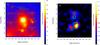 |
Fig. 1 a) LAT counts map of the 14° × 14° ROI. The counts map is smoothed with a Gaussian of kernel 0.7°. The green crosses indicate the position of the point-like sources within 7° of Cen A. b) Residual maps of lobes after subtracting the diffuse background, the point-like sources, and the Cen A core. The green contours indicate Planck 30 GHz lobe contours. |
The analysis of this section includes the Fermi-LAT data from the directions of the two giant radio lobes. We selected observations from August 4, 2008 (MET 239557417) until June 27, 2015 (MET 457063584) and used photons in the energy range between 60 MeV and 30 GeV. A 14° × 14° square region centred at the location of Cen A (RA = 201°21′54′′, Dec = −43°1′9′′) was selected as the region of interest (ROI). We selected both the front and back converted photons. To reduce the background contamination from the Earth’s albedo, the events from directions >90° were excluded from the analysis. We adopted the version P8R2_SOURCE_V6 of the instrument response function (IRF) provided by the Fermi-LAT collaboration. The binned likelihood analysis implemented in science tool gtlike was used to evaluate the spectrum.
To define the initial source list, we used the four-year catalogue (3FGL; The Fermi-LAT Collaboration 2015) by running the make3FGLxml script1. In the initial list, the spectral parameters of point-like sources within the ROI were left as free parameters. Also, we used the default spatial template for giant lobes provided by Fermi collaboration was used. We used the Fermi models of Galactic diffuse and isotropic emission provided by the Fermi team2 for the foreground components. In the fitting, the normalisations of both components were left as free parameters.
2.1. Spatial analysis
For morphology studies, we also built our own templates directly from the γ-ray residual maps. We applied gtlike with the initial source list and derived a fitted model. Then we produced the residual maps by removing the contribution from the diffuse background and all catalogue sources except the giant lobes. We also masked the inner 1° nucleus of Cen A to prevent the contamination from that region. Finally, we divided the residual maps into north and south lobes. Generally speaking, high energy maps with higher angular resolution are more suitable for the spatial analysis, but low statistics in the higher energy range may prevent any improvement. To address this problem, we applied the procedure described above to the energy range >1000 MeV and >100 MeV, respectively. The resulting spatial templates are labelled as T1 (>1000 MeV) and T2 (>100 MeV).
We used the residual templates T1 and T2, as well as the default spatial templates provided by the Fermi team3 (T3), to model the giant lobes, and applied gtlike to three models in the energy range above 100 MeV. The resulting TS and –log(Likelihood) values are listed in Table 1. In the case of template T1, the core of Cen A is clearly visible with a test statistic of TS > 7000, corresponding to a detection significance of 84σ. Extended emission to the north and south of the lobes of Cen A is detected with significances of TS > 450(21σ) and TS > 1500(39σ), respectively. The –log(Likelihood) for T1 is significantly smaller than that of T2 and T3. Therefore, for our analysis, we selected template T1. The Fermi-LAT counts map produced for the >1000 MeV data set, is shown in Fig. 1a; the green crosses show the position of point-like sources from the 3FGL catalogue within the ROI. The corresponding residual image (template T1) is shown in Fig. 1b. For comparison, the Planck 30 GHz lobe contours (green contours) are also plotted in the image. It can be seen that both the north and south lobes of the HE γ-ray emission extend beyond the radio lobes.
2.2. Spectral analysis
To derive the SED, we divided the energy interval between 100 MeV and 30 GeV into ten equal bins in logarithmic space and used gtlike in each bin. To extend the spectral analysis to lower energies, we also included photons with energy between 60 MeV and 100 MeV, and regarded these as the first energy bin. We applied energy dispersion correction to this energy bin. The significance of the signal detection in each energy bin exceeds TS = 8 (~3σ). The SEDs fitted with a power law are shown in Fig. 2. Correspondingly, the photon indices of the north and south lobes are (2.21 ± 0.02) and (2.29 ± 0.03), respectively. Within uncertainties, the index of the north lobe is consistent with that in Yang et al. (2012), while the index of the south lobe is slightly smaller. The integral flux above 100 MeV is (0.54 ± 0.06) × 10-7 ph cm-2 s-1 for the north lobe and (1.22 ± 0.05) × 10-7 ph cm-2 s-1 for the south lobe.
At low energy, the point spread function (PSF) of Fermi can be as large as 5°, in which case the 14° × 14° ROI used here may be not sufficient. We refit the first two energy bins using a 20° × 20° ROI to see the influence of the limited ROI. These results are also shown in Fig. 2 and are consistent with those derived from the smaller ROI.
To test the possible spectral variations from the outer regions of the lobes towards the central core, we split each lobe of template T1 into three parts. These regions are shown in Fig. 3. The contours of the spectral extraction regions were used for the Fermi-LAT analysis and the red rectangles were used for the radio and Planck data aperture photometry. The outer, middle and inner regions of the north lobe are N1, N2 and N3, respectively, and S1, S2 and S3 are, the outer, middle and inner regions of the south lobe, respectively. The circle is the core region.
We derived the SEDs (see Fig. 4) for every slice and an upper limit was calculated within 3σ confidence level for the signal that was detected with a significance of less than 2σ. We used a power-law function to fit the observed data. The upper limits in SEDs were also used to constrain the parameters of the power-law function. As shown in Fig. 4, in the north lobe N1 and N2 are consistent with each other within the uncertainties, but N3 is steeper than N1 and N2. In the south lobe, the photon indices for the three slices differ; the spectra become harder moving away from the core.
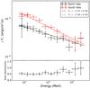 |
Fig. 2 Derived SEDs of the north lobe and south lobe, with power-law fits. The corresponding photon indices are ΓN and ΓS. The ratio of the north and south fluxes is shown in the bottom panel. For the first two energy bins, the SEDs derived using a larger ROI are also shown as bold triangles. |
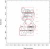 |
Fig. 3 Spectral extraction regions used for Fig. 4. The contours correspond to the γ-ray image (>1000 MeV). The red lines indicate the regions of the radio and Planck aperture photometry. The contours inside the corresponding regions show the template used for the extraction of the corresponding LAT spectrum. N1, N2, and N3 are the outer, middle, and inner regions of the north lobe, and S1, S2, and S3 are the outer, middle, and inner regions of the south lobe. The circle is the core region. |
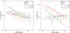 |
Fig. 4 Left plot SEDs of the slices in the north lobe. Right plot SEDs of the slices in the south lobe. The solid lines indicate the power-law fits. Γ1, Γ2, and Γ3 are the corresponding photon indices. |
3. Radio and Planck data reduction
3.1. Radio data
We used 118 MHz MWA data (McKinley et al. 2013), 408 MHz Haslem data (Haslam et al. 1982), and 1400 MHz Parkes data (O’Sullivan et al. 2013). The flux densities were measured using aperture photometry over the same subregions as the Planck data (red rectangles shown in Fig. 3). We used a ds9 plug-in radio flux measurement4 to measure the flux densities for each region and frequency. The results are listed in Table 3.
Planck characteristics of full mission maps.
3.2. Planck data
Planck5 (Tauber et al. 2010; Planck Collaboration I 2011), the third generation space mission following COBE and WMAP, was designed to measure the anisotropy of the CMB. It carries two scientific instruments and scans the sky in nine frequency bands with high sensitivity and angular resolution from 33′ to 5′. The Low-Frequency Instrument (LFI; Mandolesi et al. 2010; Bersanelli et al. 2010; Mennella et al. 2011) covers the 30, 44, and 70 GHz bands with amplifiers cooled to 20 K. The High Frequency Instrument (HFI; Lamarre et al. 2010; Planck HFI Core Team IV 2011) covers the 100, 143, 217, 353, 545, and 857 GHz bands with bolometers cooled to 0.1 K. Details about the scientific operations of the Planck can be found in Planck Collaboration I (2014) and Planck Collaboration I (2016).
In this work we use the Planck full-mission maps from Public Data Release 2 (PR2) products, which can be obtained via the Planck Legacy Archive (PLA) interface6. The Planck all-sky maps are in Healpix (Górski et al. 2005) format, with the resolution parameter Nside = 1024 for LFI 30, 44 and 70 GHz, and 2048 for LFI 70 GHz and HFI 100–857 GHz. The data are given in units of CMB thermodynamic temperature (KCMB) up to 353 GHz, and in MJy sr-1 for 545 and 857 GHz. The temperature units and MJy sr-1 were converted to flux density per pixel with multiplication by the factor given in the last column of Table 2. For ease of comparison with γ-ray emission, we degraded the resolution of the original Healpix data from 1024 or 2048 into 512 (a pixel size of about 6′), and then projected them on to the area with Fermi-LAT’s sky map using the Healpy package7 and Astropy package8. Both calibration and systematic uncertainties were considered. The zodiacal light level corrections were added to the maps, and the cosmic infrared backgrounds (CIB) were removed from the maps (Planck Collaboration I 2016). The characteristics of Planck for each frequency band are listed in Table 2.
3.3. Thermal dust and CMB components separation
In our ROI, synchrotron radiation dominates in the low frequency band. However, in the high frequency bands (>100 GHz) CMB and thermal dust emission begin to overwhelm the non-thermal emission (Planck Collaboration X 2016). It is possible to use higher frequency maps to derive accurate information on CMB anisotropy and thermal dust emission, with which we can get more robust non-thermal spectra in lower frequency than a simple aperture photometry method.
Thermal emission from dust grains dominates the radiation mechanism in the far-infrared (FIR) to millimetre range (e.g. Draine 2003; Draine & Li 2007; Compiègne et al. 2011), and is the main foreground hampering the study of Cen A at Planck frequencies. In this paper we selected a modified blackbody (MBB; Planck Collaboration XI 2014) to fit the thermal dust component empirically, that is  (1)where ν0 = 353 GHz is the reference frequency. There are three parameters in this model: the dimensionless amplitude parameter Ad, temperature Tobs, and the spectral index βobs. Because there are only a few frequency bands available, in the fitting we leave Ad and Tobs to be free and fix the index βobs to be the value in the Planck all-sky model of thermal dust emission (Planck Collaboration XI 2014) from PLA.
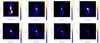 |
Fig. 5 From top left to bottom right: radio/microwave images of the Cen A and surrounding field at 118, 408, 1400 MHz, 30, 44, 70, 100, and 143 GHz. The Planck maps are cleaned maps, which are used to measure the flux densities (see Sect. 3.3 in details). These images are smoothed using a Gaussian kernel 0.3°. |
Flux density measurements of the regions of Cen A at low frequencies.
Another foreground is the CMB. A blackbody with the TCMB = 2.7255 K (Fixsen 2009) is selected to fit the CMB component  (2)where ACMB is a dimensionless amplitude parameter.
In order to derive the emission signals of Cen A in the low energy band from 30 to 143 GHz accurately, we used the Planck 217, 353, 545, and 857 GHz, and IRAS 3000 GHz (100 μm) data to constrain the parameters Ad, Tobs, and ACMB at each pixel using a chi-squared (χ2) minimisation, and then extrapolated the two models to low energy. Here we manipulated the 100 μm data following the method described in Planck Collaboration XI (2014).
Considering the effects of both the parameter uncertainties of the models (CMB and thermal dust) and the errors of the observed Planck data, we performed the following steps in deriving the microwave flux and errors of the lobes. (1) For any pixel within the ROI, we drew 50 groups of random samples from a normal (Gaussian) distribution for the free parameter set (ACMB, Ad, and Tobs) according to the best-fitted value and fitted uncertainties. The same procedure was also applied to the observed Planck data in each pixel. The observed uncertainties should obey a Poisson distribution rather than a Gaussian, but the large counts of the Planck maps makes Gaussian statistics a reasonable assumption. (2) For each group of samples, we calculated the thermal dust and CMB components based on Eqs. (1)and 2, respectively. The thermal dust and CMB maps were both smoothed to the Planck original angular resolution (listed in Table 2) to obtain a matched resolution map. Then we removed the CMB and thermal dust component to derive the background subtracted value of this pixel in each sample. (3) We chose the average and standard deviation of the 50 sampled background subtracted values as the final cleaned value and corresponding errors in this pixel. (4) We repeated steps (1) to (3) at each pixel within the ROI, and finally derived the CMB and dust emission subtracted cleaned maps and corresponding error maps, which were used to measure the integral flux densities in the following. The derived cleaned maps from 30 GHz to 143 GHz are shown in Fig. 5.
3.4. Flux density measurements
We used the standard aperture photometry, with the aperture size (red rectangles) shown in Fig. 3, to measure the integral flux densities of the Planck 30, 44, 70, 100, and 143 GHz maps. The measurements of flux density for each region and frequency, together with errors within 1σ confidence level, are listed in Table 3. The errors were derived from the error maps described above using error propagation. We can see the flux densities of the core are consistent with their corresponding values of region 3 in Hardcastle et al. (2009), which confirm that our model selection and method are reasonable.
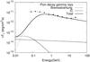 |
Fig. 6 γ-rays from hadronic interactions of cosmic rays in different channels. Also shown is the SED of the south lobe. The primary proton spectra are assumed to be a power-law function with an index of 2.3 to fit the high energy part of the SED of the south lobe. |
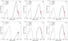 |
Fig. 7 Broadband SEDs for each region shown in Fig. 3. Observed radio and Planck data (black dots with error bars) are fitted with a synchrotron model. Observed Fermi-LAT data (red dots with error bars) are fitted with the inverse-Compton (IC) scatterings of the CMB and EBL photon fields except for S1, which only requires the seed photon contribution from the CMB. The upper limits are calculated within a 3σ confidence level. |
Summary of SED best-fitting model parameters for the power-law electron distribution with cutoff.
4. Modelling the spectral energy distributions
To fit the derived spectral distributions, we used the software package Naima9. We found that a power-law shape of the spectrum is extended down to 100 MeV. This does not agree with the spectrum of low energy γ-rays from hadronic interactions of cosmic rays. The latter has a standard shape, which is dictated by the kinematics of the π0 decay rather than the spectrum of cosmic rays. The region of sharp decline of the SED of π0-decay γ-rays below 1 GeV is partly “filled” by photons generated by secondary electrons (through the IC scattering and Bremsstrahlung), that is the products of the charged π±-meson decays. However, these components do not appear to sufficiently compensate the deficit even in the most optimistic case of “thick target” when the production of secondaries is saturated. This is demonstrated in Fig. 6, which shows the three channels of γ-ray production initiated by pp interactions and the SED of south lobe. It is assumed that the density of the ambient gas n is sufficiently high that the lifetimes of relativistic protons,  , as well as secondary electrons, are shorter than the confinement time of cosmic rays. Under this condition, the steady-state solutions shown in Fig. 6 apparently do not depend on the density n. The relative contribution of γ-rays from secondary electrons does not strongly depend on the spectrum of cosmic rays. We can safely conclude that low energy γ-rays from both lobes are not contributed by cosmic ray protons and nuclei.
Thus, the spectral measurements presented in this paper remove the uncertainty of our previous study, Yang et al. (2012), regarding the origin of γ-rays. It is clear that γ-rays are produced, at least in the energy band below 1 GeV, by directly accelerated electrons. Because of the low gas density in the lobes, the γ-ray production is dominated by the IC scatterings of photons of the 2.7 K CMB radiation, with possible contribution from photons of the EBL by relativistic electrons. Although the energy density of the EBL is much lower than the energy density of the CMB, the role of the EBL photons can be noticeable in the formation of the spectrum at the highest γ-ray energies, especially in the case of a cutoff in the electron spectrum below a few TeV. The photons from the host galaxy of Cen A are also potential seed photons for IC scattering. As calculated in Abdo et al. (2010), however, the IC γ rays from the photon fields produced by the host galaxy are negligible compared with those from the CMB and EBL.
For different parts of the lobes, the distributions of electrons and the strength of the magnetic fields can be derived from the fit of the Planck radio and the Fermi-LAT γ-ray data by synchrotron and IC components, respectively. We used the formalism of Aharonian et al. (2010) for calculations of synchrotron radiation and the formalism proposed in Khangulyan et al. (2014) for IC scattering. The temperature TCMB = 2.7255 K and energy density nCMB = 0.261 eV cm-3 were adopted for the CMB photon field. We used the model of Franceschini et al. (2008) for EBL.
For the energy distribution of electrons, we assumed the following general form:  (3)Here E0 = 1 GeV is the reference energy. In calculations, the parameters A, α, Ecutoff, and β, characterising the electron spectrum, and the strength of the magnetic field B, are left as free parameters. The minimum electron energy is set to Eemin = 1 MeV. Figure 7 shows the SED results obtained for the subregions from Fig. 3. The derived model parameters Ecutoff, β, B, and the corresponding errors with 1σ confidence level, as well as the total energy of electrons We, are presented in Table 4 for the regions N1, N2, N3 and S1, S2, S3. It should be mentioned that for N2, N3, S2, and S3, the Planck data points above 70 GHz are significantly above the model predicted value and we omit these points in the fit. The reason may be a poor understanding of the high frequency background in this band. Meanwhile, for N2 and N3 the high Fermi points are significantly above the model curve; this is caused by the fact that the weighting of these high energy points in MCMC fitting is relatively small owing to their larger error bars.
We should note that in this study we found, in contrast to the statement of our previous paper (Yang et al. 2012), that the EBL photons appear important (except for the region S1), as target photons for the IC scattering, to fit the γ-ray data. The reason is that now the additional Planck data provide stringent constraints on the cutoff regions of the electron spectrum.
For all regions, except for S1, the γ-ray spectra correspond to electrons from the post-cutoff region. Meanwhile the radio data are produced by electrons from the pre-cutoff region. This follows from the essentially different indices of the radio and γ-ray spectra. The region S1 is of special interest because of lack of any indication for a cut off in both the radio and γ-ray spectra. In this region, the γ-ray and radio data points can be fitted with a pure power-law electron spectrum up to 1 TeV. Another special feature of this region is that the derived magnetic field is about 10 μG, which is much higher than in other regions. This value exceeds by an order of magnitude the strength of the magnetic field typically assumed for the radio lobes (see e.g. McKinley et al. 2015).
The dynamical ranges of both the radio and γ-ray data points are relatively small, therefore the power-law electron spectrum with a cutoff is not an unique explanation of the data. For example, the broken power-law function, given in the form 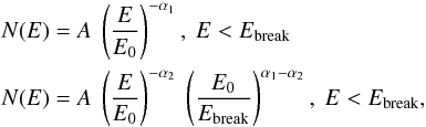 (4)can fit the radio and γ-ray data equally well. The results are shown in Fig. 8. The best-fit parameters are summarised in Table 5. We did not apply this electron distribution to the region S1 since the latter is explained by a pure power-law spectrum. The differences in the indices before and after the break are significantly larger than 1. This implies that the break cannot be a result of radiative cooling, but rather is a characteristic feature of the acceleration spectrum.
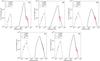 |
Fig. 8 Same as Fig. 7 but for broken power-law electron distributions. |
Summary of SED best-fit model parameters for a broken power-law electron distribution.
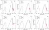 |
Fig. 9 Same as Fig. 7 but for a hybrid model in which both leptonic and hadronic process contribute. |
Summary of SED best-fit parameters in the leptonic-hadronic model.
As mentioned above, at low energies, E ≤ 1 GeV, the γ-ray data can be explained only by directly accelerated electrons. However, we cannot exclude a significant contribution by a hadronic component to the overall γ-ray emission. Moreover, an additional hadronic component helps us to improve the fit of γ-ray spectra. In particular, the hadronic γ-ray emission could be considered as an alternative to the IC scattering on the EBL photons. Such an attempt to fit the radio and γ-ray SEDs successfully, with an involvement of an additional hadronic component, is demonstrated in Fig. 9. In this case IC scattering from CMB contributes to the low energy part of γ-rays, while the π0 decays contribute to the high energy tail. This is similar, to some extent, to the modelling of the radio lobes of Fornax A in McKinley et al. (2015), where the X-ray flux is due to the IC scattering, and γ-rays are from the π0-decays.
To reduce the number of free parameters, in the “IC+π0” model we fix the magnetic field and electron spectrum to the best-fit values from the pure leptonic models described above. The only exception was the peculiar S1 region, for which we fixed the magnetic field to the value of 1 μG, i.e. by a factor of 10 smaller than in the pure IC scenarios. We adopt the parametrisation of neutral pion decay described in Kafexhiu et al. (2014) in the π0 model calculation. We also fix the gas density, n = 10-4 cm-3. Then, the remaining two free parameters are the spectral index α, and the total energy in protons, Wp. The derived values of these parameters are presented in Table 6. The power-law indices of the proton spectra in the different regions are similar with an average value close to 2.5. The only exception is the region S1, where the photon spectrum is very hard with α ~ 2. The total energy in relativistic protons in S1 is also different; it is significantly higher than in other regions. On the other hand, the additional hadronic component permits the reduction of the magnetic field to a nominal value of about 1 μG. Finally, in the south lobe we see a hardening of the proton spectrum. Interestingly, such an effect has also been seen in Fermi bubbles (Su et al. 2010; Ackermann et al. 2014; Yang et al. 2014), which are two giant, ~10 kpc scale, γ-ray structures belonging to our Galaxy.
5. Conclusion and discussion
We have analysed the SEDs of the giant lobes of Cen A across a wide range of energies. The presented results increase the significance of the γ-ray detections reported before, and, more importantly, significantly extend the γ-ray spectrum down to 60 MeV and up to 30 GeV. This allows us to make rather robust conclusions regarding the origin of different components of the γ-ray emission.
We confirm the different morphologies of the giant lobes in γ-rays and at radio frequencies. This can be explained by the fact that the morphology of synchrotron radiation is strongly affected by the spatial distribution of the magnetic field. Also, the electrons responsible for γ-ray emission have higher energies than the electrons producing synchrotron emission in the lobes. To minimise the energy gap between the electrons responsible for the IC and synchrotron electrons, we further analysed the high frequency Planck data.
We divided both lobes into three regions and found significant spectral variations between regions. The power-law shape of the SED down to 100 MeV provides evidence against the hadronic origin of the emission. On the other hand, the extension of γ-ray emission well beyond 10 GeV, and the inclusion of the Planck data permits more comprehensive spectral studies and broadband modelling of the SEDs. All regions in the south and north lobes, except for the region S1, can be naturally explained within a pure leptonic model in which the γ-rays are produced because of the IC scattering of electrons on the CMB photons with a non-negligible contribution from the EBL photons. The magnetic field and the total energy in relativistic electrons in the lobes, which are derived from a comparison of the SED modelling and the Fermi-LAT and Planck data, are about 1 μG and We ≈ 6 × 1057 erg.
The region S1 has very different radiation characteristics compared to the other regions. This is the only region where the radio and γ-ray components have the same spectral index, and a single power-law electron spectrum is required without a break or cutoff up to energies of 1 TeV. Although the SED of the region S1 can also be explained within a simple leptonic model, it however requires an unusually large magnetic field, B ≃ 13 μG, which is an order of magnitude larger than the average field in the lobes. On the other hand, the total energy of electrons in S1 is much smaller than in other regions, by a factor of 3 to 15. Thus, the ratio of pressures due to the magnetic field and relativistic electrons in S1 differs by 2 to 3 orders of magnitude from the average value in the lobes.
An alternative explanation for the peculiar features of S1 could be the effect of a non-negligible contribution of a new radiation component, presumably of hadronic origin. This contribution, on the top of the IC component, should become significant only at high energies, therefore does not contradict the above claim that γ-rays below 1 GeV should be dominated by the IC scattering of electrons.
Indeed if we ignore the IC component from EBL, which is poorly constrained, the γ-ray spectra in all regions can be interpreted as a combination of two components: IC scattering on CMB photons and hadronic γ-rays from the pion decays. The derived total proton energy budget is of the order of 5 × 1060 erg, which is consistent with the estimation in Yang et al. (2012). Such energy could only be accumulated on a timescale as long as 109 yr, assuming an injection rate of the order of 1044 erg. The diffusion coefficient of cosmic rays in this case can be estimated from the condition of their propagation to distances of order of 100 kpc: 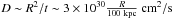 . The hardening of the spectrum of cosmic rays in the south lobe is similar to the spectral hardening towards the edge of Fermi bubbles (Su et al. 2010; Ackermann et al. 2014; Yang et al. 2014), which may be related to the energy dependent propagation of cosmic rays.
A possible problem of the leptonic-hadronic model applied to the lobes of Cen A is the huge overall energy required in relativistic protons. It exceeds the total energy in the magnetic field by two orders of magnitude. This problem, however, can be reduced if we assume that the γ-ray production at p-p collisions takes place primarily in the filamentary structures of the lobes. This is similar to the idea in Crocker et al. (2014), who proposed that the collapse of thermally unstable plasma inside Fermi bubbles can lead to an accumulation of cosmic rays and magnetic field into localised filamentary condensations of higher density gas. If this is the case in the giant radio lobes of Cen A as well, the required energy budget in CRs can significantly reduce the required cosmic ray energy budget.
Concerning the relativistic electrons, their origin remains a mystery. The huge size of the giant lobes makes it impossible to transport the relativistic electrons from the core of Cen A. More specifically, the SED fitting results show that we need uncooled electrons of energy up to 50 GeV in the north lobe. The cooling time of 50 GeV electrons can be estimated as  , where w is the energy density of the ambient radiation and magnetic fields in unit of eV cm-3 and γ is the Lorentz factor of the electrons. The propagation length of electrons during the cooling time is then
 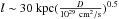 , i.e. far less than the size of the lobe. The only solution is the in situ acceleration of the electrons, such as the stochastic acceleration in a turbulent magnetic field.
References
- Abdo, A. A., Ackermann, M., Ajello, M., et al. 2010, Science, 328, 725 [NASA ADS] [CrossRef] [PubMed] [Google Scholar]
- Ackermann, M., Albert, A., Atwood, W. B., et al. 2014, ApJ, 793, 64 [NASA ADS] [CrossRef] [Google Scholar]
- Aharonian, F. A., Kelner, S. R., & Prosekin, A. Y. 2010, Phys. Rev. D, 82, 043002 [NASA ADS] [CrossRef] [Google Scholar]
- Alvarez, H., Aparici, J., May, J., & Reich, P. 2000, A&A, 355, 863 [NASA ADS] [Google Scholar]
- Bersanelli, M., Mandolesi, N., Butler, R. C., et al. 2010, A&A, 520, A4 [NASA ADS] [CrossRef] [EDP Sciences] [Google Scholar]
- Burns, J. O., Feigelson, E. D., & Schreier, E. J. 1983, ApJ, 273, 128 [NASA ADS] [CrossRef] [Google Scholar]
- Cappellari, M., Neumayer, N., Reunanen, J., et al. 2009, MNRAS, 394, 660 [NASA ADS] [CrossRef] [Google Scholar]
- Combi, J. A., & Romero, G. E. 1997, A&AS, 121, 11 [NASA ADS] [CrossRef] [EDP Sciences] [Google Scholar]
- Compiègne, M., Verstraete, L., Jones, A., et al. 2011, A&A, 525, A103 [NASA ADS] [CrossRef] [EDP Sciences] [Google Scholar]
- Crocker, R. M., Bicknell, G. V., Carretti, E., Hill, A. S., & Sutherland, R. S. 2014, ApJ, 791, L20 [NASA ADS] [CrossRef] [Google Scholar]
- Draine, B. T. 2003, ARA&A, 41, 241 [NASA ADS] [CrossRef] [Google Scholar]
- Draine, B. T., & Li, A. 2007, ApJ, 657, 810 [NASA ADS] [CrossRef] [Google Scholar]
- Eilek, J. A. 2014, New J. Phys., 16, 045001 [NASA ADS] [CrossRef] [Google Scholar]
- Fixsen, D. J. 2009, ApJ, 707, 916 [Google Scholar]
- Franceschini, A., Rodighiero, G., & Vaccari, M. 2008, A&A, 487, 837 [NASA ADS] [CrossRef] [EDP Sciences] [Google Scholar]
- Górski, K. M., Hivon, E., Banday, A. J., et al. 2005, ApJ, 622, 759 [NASA ADS] [CrossRef] [Google Scholar]
- Hardcastle, M. J., Cheung, C. C., Feain, I. J., & Stawarz, Ł. 2009, MNRAS, 393, 1041 [NASA ADS] [CrossRef] [Google Scholar]
- Harris, G. L. H., Rejkuba, M., & Harris, W. E. 2010, PASA, 27, 457 [NASA ADS] [CrossRef] [Google Scholar]
- Haslam, C. G. T., Salter, C. J., Stoffel, H., & Wilson, W. E. 1982, A&AS, 47, 1 [NASA ADS] [Google Scholar]
- Israel, F. P. 1998, A&ARv, 8, 237 [NASA ADS] [CrossRef] [Google Scholar]
- Kafexhiu, E., Aharonian, F., Taylor, A. M., & Vila, G. S. 2014, Phys. Rev. D, 90, 123014 [NASA ADS] [CrossRef] [Google Scholar]
- Khangulyan, D., Aharonian, F. A., & Kelner, S. R. 2014, ApJ, 783, 100 [NASA ADS] [CrossRef] [Google Scholar]
- Lamarre, J.-M., Puget, J.-L., Ade, P. A. R., et al. 2010, A&A, 520, A9 [NASA ADS] [CrossRef] [EDP Sciences] [Google Scholar]
- Mandolesi, N., Bersanelli, M., Butler, R. C., et al. 2010, A&A, 520, A3 [NASA ADS] [CrossRef] [EDP Sciences] [Google Scholar]
- McKinley, B., Briggs, F., Gaensler, B. M., et al. 2013, MNRAS, 436, 1286 [NASA ADS] [CrossRef] [Google Scholar]
- McKinley, B., Yang, R., López-Caniego, M., et al. 2015, MNRAS, 446, 3478 [NASA ADS] [CrossRef] [Google Scholar]
- Mennella, A., Bersanelli, M., Butler, R. C., et al. 2011, A&A, 536, A3 [NASA ADS] [CrossRef] [EDP Sciences] [Google Scholar]
- O’Sullivan, S. P., Feain, I. J., McClure-Griffiths, N. M., et al. 2013, ApJ, 764, 162 [NASA ADS] [CrossRef] [Google Scholar]
- Planck Collaboration I. 2011, A&A, 536, A1 [NASA ADS] [CrossRef] [EDP Sciences] [Google Scholar]
- Planck Collaboration I. 2014, A&A, 571, A1 [NASA ADS] [CrossRef] [EDP Sciences] [Google Scholar]
- Planck Collaboration XI. 2014, A&A, 571, A11 [NASA ADS] [CrossRef] [EDP Sciences] [Google Scholar]
- Planck Collaboration I. 2016, A&A, 594, A1 [NASA ADS] [CrossRef] [EDP Sciences] [Google Scholar]
- Planck Collaboration X. 2016, A&A, 594, A10 [NASA ADS] [CrossRef] [EDP Sciences] [Google Scholar]
- Planck HFI Core Team IV. 2011, A&A, 536, A4 [NASA ADS] [CrossRef] [EDP Sciences] [Google Scholar]
- Shain, C. A. 1958, Aust. J. Phys., 11 [Google Scholar]
- Stefan, I. I., Carilli, C. L., Green, D. A., et al. 2013, MNRAS, 432, 1285 [NASA ADS] [CrossRef] [Google Scholar]
- Su, M., Slatyer, T. R., & Finkbeiner, D. P. 2010, ApJ, 724, 1044 [NASA ADS] [CrossRef] [Google Scholar]
- Tauber, J. A., Mandolesi, N., Puget, J.-L., et al. 2010, A&A, 520, A1 [NASA ADS] [CrossRef] [EDP Sciences] [Google Scholar]
- The Fermi-LAT Collaboration 2015, ApJS, 218, 23 [Google Scholar]
- Wykes, S., Croston, J. H., Hardcastle, M. J., et al. 2013, A&A, 558, A19 [NASA ADS] [CrossRef] [EDP Sciences] [Google Scholar]
- Wykes, S., Intema, H. T., Hardcastle, M. J., et al. 2014, MNRAS, 442, 2867 [NASA ADS] [CrossRef] [Google Scholar]
- Yang, R.-Z., Sahakyan, N., de Ona Wilhelmi, E., Aharonian, F., & Rieger, F. 2012, A&A, 542, A19 [NASA ADS] [CrossRef] [EDP Sciences] [Google Scholar]
- Yang, R.-Z., Aharonian, F., & Crocker, R. 2014, A&A, 567, A19 [NASA ADS] [CrossRef] [EDP Sciences] [Google Scholar]
All Tables
Summary of SED best-fitting model parameters for the power-law electron distribution with cutoff.
Summary of SED best-fit model parameters for a broken power-law electron distribution.
All Figures
|
Fig. 1 a) LAT counts map of the 14° × 14° ROI. The counts map is smoothed with a Gaussian of kernel 0.7°. The green crosses indicate the position of the point-like sources within 7° of Cen A. b) Residual maps of lobes after subtracting the diffuse background, the point-like sources, and the Cen A core. The green contours indicate Planck 30 GHz lobe contours. |
| In the text | |
|
Fig. 2 Derived SEDs of the north lobe and south lobe, with power-law fits. The corresponding photon indices are ΓN and ΓS. The ratio of the north and south fluxes is shown in the bottom panel. For the first two energy bins, the SEDs derived using a larger ROI are also shown as bold triangles. |
| In the text | |
|
Fig. 3 Spectral extraction regions used for Fig. 4. The contours correspond to the γ-ray image (>1000 MeV). The red lines indicate the regions of the radio and Planck aperture photometry. The contours inside the corresponding regions show the template used for the extraction of the corresponding LAT spectrum. N1, N2, and N3 are the outer, middle, and inner regions of the north lobe, and S1, S2, and S3 are the outer, middle, and inner regions of the south lobe. The circle is the core region. |
| In the text | |
|
Fig. 4 Left plot SEDs of the slices in the north lobe. Right plot SEDs of the slices in the south lobe. The solid lines indicate the power-law fits. Γ1, Γ2, and Γ3 are the corresponding photon indices. |
| In the text | |
|
Fig. 5 From top left to bottom right: radio/microwave images of the Cen A and surrounding field at 118, 408, 1400 MHz, 30, 44, 70, 100, and 143 GHz. The Planck maps are cleaned maps, which are used to measure the flux densities (see Sect. 3.3 in details). These images are smoothed using a Gaussian kernel 0.3°. |
| In the text | |
|
Fig. 6 γ-rays from hadronic interactions of cosmic rays in different channels. Also shown is the SED of the south lobe. The primary proton spectra are assumed to be a power-law function with an index of 2.3 to fit the high energy part of the SED of the south lobe. |
| In the text | |
|
Fig. 7 Broadband SEDs for each region shown in Fig. 3. Observed radio and Planck data (black dots with error bars) are fitted with a synchrotron model. Observed Fermi-LAT data (red dots with error bars) are fitted with the inverse-Compton (IC) scatterings of the CMB and EBL photon fields except for S1, which only requires the seed photon contribution from the CMB. The upper limits are calculated within a 3σ confidence level. |
| In the text | |
|
Fig. 8 Same as Fig. 7 but for broken power-law electron distributions. |
| In the text | |
|
Fig. 9 Same as Fig. 7 but for a hybrid model in which both leptonic and hadronic process contribute. |
| In the text | |
Current usage metrics show cumulative count of Article Views (full-text article views including HTML views, PDF and ePub downloads, according to the available data) and Abstracts Views on Vision4Press platform.
Data correspond to usage on the plateform after 2015. The current usage metrics is available 48-96 hours after online publication and is updated daily on week days.
Initial download of the metrics may take a while.