| Issue |
A&A
Volume 604, August 2017
|
|
|---|---|---|
| Article Number | A6 | |
| Number of page(s) | 40 | |
| Section | Interstellar and circumstellar matter | |
| DOI | https://doi.org/10.1051/0004-6361/201730426 | |
| Published online | 26 July 2017 | |
The physical and chemical structure of Sagittarius B2
II. Continuum millimeter emission of Sgr B2(M) and Sgr B2(N) with ALMA⋆
1 I. Physikalisches Institut, Universität zu Köln, Zülpicher Str. 77, 50937 Köln, Germany
e-mail: sanchez@ph1.uni-koeln.de
2 Max-Planck Institute for Extraterrestrial Physics, Giessenbachstrasse 1, 85748 Garching bei München, Germany
3 National Radio Astronomy Observatory, 1003 Lopezville Road, Socorro, NM 87801, USA
4 European Southern Observatory, Karl-Schwarzschild-Strasse 2, 85748 Garching bei München, Germany
5 INAF–Osservatorio Astrofisico di Arcetri, Largo E. Fermi 5, 50125 Firenze, Italy
6 LERMA, Observatoire de Paris, PSL Research University, CNRS, Sorbonne Universités, UPMC Univ. Paris 06, 75014 Paris, France
7 California Institute of Technology, Pasadena, CA 91125, USA
8 Department of Astronomy, Yunnan University, and Key Laboratory of Astroparticle Physics of Yunnan Province, 650091 Kumming, PR China
9 Department of Astronomy, University of Michigan, 500 Church Street, Ann Arbor, MI 48109-1042, USA
Received: 12 January 2017
Accepted: 4 April 2017
Context. The two hot molecular cores Sgr B2(M) and Sgr B2(N), which are located at the center of the giant molecular cloud complex Sagittarius B2, have been the targets of numerous spectral line surveys, revealing a rich and complex chemistry.
Aims. We seek to characterize the physical and chemical structure of the two high-mass star-forming sites Sgr B2(M) and Sgr B2(N) using high-angular resolution observations at millimeter wavelengths, reaching spatial scales of about 4000 au.
Methods. We used the Atacama Large Millimeter/submillimeter Array (ALMA) to perform an unbiased spectral line survey of both regions in the ALMA band 6 with a frequency coverage from 211 GHz to 275 GHz. The achieved angular resolution is 0.̋4, which probes spatial scales of about 4000 au, i.e., able to resolve different cores and fragments. In order to determine the continuum emission in these line-rich sources, we used a new statistical method, STATCONT, which has been applied successfully to this and other ALMA datasets and to synthetic observations.
Results. We detect 27 continuum sources in Sgr B2(M) and 20 sources in Sgr B2(N). We study the continuum emission variation across the ALMA band 6 (i.e., spectral index) and compare the ALMA 1.3 mm continuum emission with previous SMA 345 GHz and VLA 40 GHz observations to study the nature of the sources detected. The brightest sources are dominated by (partially optically thick) dust emission, while there is an important degree of contamination from ionized gas free-free emission in weaker sources. While the total mass in Sgr B2(M) is distributed in many fragments, most of the mass in Sgr B2(N) arises from a single object, with filamentary-like structures converging toward the center. There seems to be a lack of low-mass dense cores in both regions. We determine H2 volume densities for the cores of about 107–109 cm-3 (or 105–107 M⊙ pc-3), i.e., one to two orders of magnitude higher than the stellar densities of super star clusters. We perform a statistical study of the chemical content of the identified sources. In general, Sgr B2(N) is chemically richer than Sgr B2(M). The chemically richest sources have about 100 lines per GHz and the fraction of luminosity contained in spectral lines at millimeter wavelengths with respect to the total luminosity is about 20%–40%. There seems to be a correlation between the chemical richness and the mass of the fragments, where more massive clumps are more chemically rich. Both Sgr B2(N) and Sgr B2(M) harbor a cluster of hot molecular cores. We compare the continuum images with predictions from a detailed 3D radiative transfer model that reproduces the structure of Sgr B2 from 45 pc down to 100 au.
Conclusions. This ALMA dataset, together with other ongoing observational projects in the range 5 GHz to 200 GHz, better constrain the 3D structure of Sgr B2 and allow us to understand its physical and chemical structure.
Key words: stars: formation / stars: massive / radio continuum: ISM / radio lines: ISM / ISM: individual objects: SgrB2(M) / ISM: individual objects: SgrB2(N)
FITS files of the continuum images as well as the spectral index are available at the CDS via anonymous ftp to cdsarc.u-strasbg.fr (130.79.128.5) or via http://cdsarc.u-strasbg.fr/viz-bin/qcat?J/A+A/604/A6
© ESO, 2017
1. Introduction
The giant molecular cloud complex Sagittarius B2 (hereafter Sgr B2) is the most massive region with ongoing star formation in the Galaxy. It is located at a distance of 8.34 ± 0.16 kpc (Reid et al. 2014) and thought to be within less than 100 pc in projected distance to the Galactic center (Molinari et al. 2010). The high densities (>105 cm-3) and relatively warm temperatures (~ 50–70 K), together with its proximity to the Galactic center, make Sgr B2 an interesting environment of extreme star formation, that is different from the typical star-forming regions in the Galactic disk but similar to the active galactic centers that dominate star formation throughout the Universe at high redshifts.
 |
Fig. 1 Sketch of the setup of the ALMA correlator during the spectral scan observations in the ALMA band 6. The observations are divided into two frequency ranges: low frequencies from 211 to 246 GHz and high frequencies from 240 to 275 GHz. Each frequency tuning is depicted with a different color, while the different boxes refer to the four spectral windows per tuning. The number of the spectral windows, as given in the ALMA observations, are given on top of each box. The gray line shows the transmission of the atmosphere at the ALMA site with a precipitable water vapor of 0.7 mm. |
The whole Sgr B2 complex contains a total mass of about 107 M⊙ (with a total luminosity of about 107L⊙, Goldsmith et al. 1990) distributed in a large envelope of about 22 pc in radius (Lis & Goldsmith 1989; see also Schmiedeke et al. 2016). Despite the large mass reservoir, star formation seems to be mainly occurring in the two hot molecular cores Sgr B2(M) and Sgr B2(N). These two sites of active star formation are located at the center of the envelope, occupy an area of around 2 pc in radius, contain at least 70 high-mass stars with spectral types from O5 to B0 (e.g., De Pree et al. 1998, 2014; Gaume et al. 1995), and constitute one of the best laboratories for the search of new chemical species in the Galaxy (e.g., Belloche et al. 2013, 2014; Schilke et al. 2014). Schmiedeke et al. (2016) provide a more detailed description of Sgr B2 and the two hot cores.
Owing to their exceptional characteristics, Sgr B2(M) and Sgr B2(N) have been the targets of numerous spectral line surveys with instruments such as the IRAM 30 m telescope and the Herschel space observatory (e.g., Nummelin et al. 1998; Bergin et al. 2010; Belloche et al. 2013; Neill et al. 2014; Corby et al. 2015). These studies, although lacking information on the spatial structure of the cores, have revealed a very different chemical composition of the two objects, where Sgr B2(M) is very rich in sulphur-bearing species and Sgr B2(N) in complex organic molecules. High-angular (sub-arcsecond) resolution observations at (sub)millimeter wavelengths were conducted for the first time by Qin et al. (2011) using the Submillimeter Array (SMA) at 345 GHz. The authors find different morphologies in the two objects; Sgr B2(M) is highly fragmented into many cores and Sgr B2(N) remains, at least at the sensitivity and image fidelity of the SMA observations, monolithic consisting of only a main core and a northern, secondary core.
With the aim of better understanding the physical and chemical structure of these two active high-mass star-forming sites, we started an ALMA project in Cycle 2 to perform an unbiased spectral line survey of Sgr B2(M) and Sgr B2(N) in the ALMA band 6 (from 211 to 275 GHz). This is the second in a series of papers investigating the structure of Sgr B2. In the Paper I of this series (Schmiedeke et al. 2016), we present a 3D radiative transfer model of the whole Sgr B2 region. In the current paper we describe the ALMA project, apply a new method to determine the continuum emission in line-rich sources such as Sgr B2, and compare the obtained continuum images with previous high-angular resolution observations at different wavelengths (e.g., Qin et al. 2011; Rolffs et al. 2011) and with predictions from the 3D radiative transfer model presented by Schmiedeke et al. (2016).
This paper is organized as follows. In Sect. 2 we describe our ALMA observations. In Sect. 3 we study the continuum emission toward Sgr B2(M) and Sgr B2(N) and identify the compact sources and main structures. In Sect. 4 we analyze and discuss our findings focusing on the properties of the continuum sources and their possible origin and chemical content and we compare our findings with a 3D radiative transfer model. Finally, in Sect. 5 we summarize the main results and draw the conclusions.
2. Observations
Sgr B2 was observed with ALMA (Atacama Large Millimeter/submillimeter Array; ALMA Partnership et al. 2015) during Cycle 2 in 2014 June and 2015 June (project number 2013.1.00332.S), using 34–36 antennas in an extended configuration with baselines in the range from 30 m to 650 m, which in the frequency range 211–275 GHz results in a sensitivity to structures in the range 0.̋4–5′′. The observations were carried out in the spectral scan mode covering the broad frequency range from 211 GHz to 275 GHz (ALMA band 6) with 10 different spectral tunings. For each tuning, the digital correlator was configured in four spectral windows of 1875 MHz and 3840 channels each (with dual polarization), providing a resolution of 0.5–0.7 km s-1 across the full frequency band. In Fig. 1, we show a sketch of the frequency coverage. The two sources Sgr B2(M) and Sgr B2(N) were observed in track-sharing mode, with phase centers at α(J2000 , δ(J2000
 for Sgr B2(M), and at α(J2000
 , δ(J2000
 for Sgr B2(N). Flux calibration was obtained through observations of the bright quasar J1733−1304 (flux 1.36 Jy at 228.265 GHz, with spectral index − 0.71) and the satellite Titan. The phases were calibrated by interleaved observations of the quasars J1744−3116 (bootstrapped flux of 0.39 Jy at 228.265 GHz, with spectral index − 0.55) and J1752−2956 (bootstrapped flux of 0.031 Jy at 228.265 GHz, with spectral index − 0.99). The gain calibrators, separated from Sgr B2 on the sky by ~ 2–3°, were observed every 6 min. The bandpass correction was obtained by observing the bright quasar J1733−1304. The on-source observing time per source and frequency was about 2.5 min. The amount of precipitable water vapor during the different observing days was about 0.7 mm.
The calibration and imaging were performed in CASA1 version 4.4.0. The gains of the sources were determined from the interpolation of the gains derived for the nearby quasars J1744−3116 and J1752−2956 at each corresponding frequency with the exception of spectral windows 12 to 15 (in both the low-frequency and high-frequency regimes; see Fig. 1) for which the phases of the gain calibrator were not properly determined. For these spectral windows we transferred the phases derived from nearby (in frequency and in observing time) spectral windows. This method results in a bit noiser data for the affected spectral windows, but these data are consistent with the expected results for the spectral windows 12 to 15 in the low-frequency (LF) regime. For the high-frequency (HF) regime, the dispersion of the phases is still too large. We applied two iterations of self-calibration in phase-mode only and a last step in both amplitude and phase to correct the phases of the more noisy spectral windows, using only the strongest component (or bright emission above 500 mJy) in the model. This process is used only to recover the main structure of both sources for future analysis, but we do not consider the self-calibrated images for the analysis of the continuum properties of Sgr B2(M) and (N), since the presence of extended emission can slightly modify the overall flux density scale (see, e.g., Antonucci & Ulvestad 1985). Channel maps for each spectral window were created via the task CLEAN in CASA, with the robust parameter of Briggs (1995) set equal to 0.5, as a compromise between resolution and sensitivity to extended emission. The resulting images have a synthesized CLEANed beam that varies from about  to
to  . These images were restored with a Gaussian beam to have final synthesized beams of
  (medium resolution images) and
  (super-resolution images). The medium resolution images are better suited to study the spectral line emission that will be presented in forthcoming papers, while the super-resolution images can be used to study in more detail the structure of the continuum emission. All the images are corrected for the primary beam response of the ALMA antennas. The rms noise level of each spectral channel (of 490 kHz, or 0.5–0.7 km s-1) is typically in the range 10 to 20 mJy beam-1. The final continuum image, which is produced considering the whole observed frequency range and following the procedure described in Sánchez-Monge et al. (2017, see also Sect. 3.1), has a rms noise level of 8 mJy beam-1.
3. Results
In this section we aim at identifying and characterizing the different sources and structures seen in the Sgr B2(N) and Sgr B2(M) continuum maps at 1.3 mm (211–275 GHz). We first present the continuum maps created following the method described in Sánchez-Monge et al. (2017). Then, we identify the continuum sources and main structures in the ALMA images.
3.1. Continuum maps at 1.3 mm with ALMA
We used the STATCONT2 python-based tool (see Sánchez-Monge et al. 2017) to create the continuum emission images of Sgr B2(M) and Sgr B2(N) from the spectral scan observations presented in Sect. 2. Each spectral window, corresponding to a bandwidth of 1.87 GHz, was processed independently to produce 40 different continuum emission maps throughout the frequency range 211 GHz to 275 GHz. The method used to determine the continuum level is based on the sigma-clipping algorithm (or corrected sigma-clipping method, hereafter cSCM, within the STATCONT Python-based tool). Each cube from each spectral window was inspected on a pixel basis. The spectrum was analyzed iteratively: In the first step, the median (μ) and dispersion (σ) of the entire intensity distribution is calculated. In the second step, the algorithm removes all the points that are smaller or larger than μ ± ασ, where α is set to 2. In each iteration, a number of outliers are removed and σ decreases or remains the same. The process is stopped when σ is within a certain tolerance level determined as (σold−σnew) /σnew. This method has been proved against synthetic observations to be accurate within an uncertainty level of 5–10% (see Sánchez-Monge et al. 2017). An image map of the uncertainty in the determination of the continuum level is also produced. The continuum level slightly depends on the spectral features, both in emission and absorption, contained in the spectrum. It is then important to note that each spectral window contains different molecular transitions, and therefore different spectra. Thus, the comparison of continuum images constructed from different spectral ranges permits us to confirm the real emission and to search for artifacts produced by the shape of the spectra. Furthermore, it also allows us to study how the continuum emission changes with frequency.
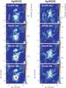 |
Fig. 2 Continuum emission maps for Sgr B2-N (left column) and Sgr B2-M (right column) produced using STATCONT as described in Sect. 3.1 for four different spectral windows, corresponding to the central frequencies 213.875 GHz, 235.500 GHz, 256.078 GHz, and 273.953 GHz from top to bottom. The synthesized beam is |
Figure 2 shows the continuum emission for Sgr B2(N) (left column) and Sgr B2(M) (right column) at different frequencies. Each column in the figure is divided into four panels with increasing frequency from top to bottom. The color scale was fixed in all the panels to better show the changes in intensity. In the following we describe the results obtained from the continuum images. The spatial structure is similar at all frequencies. The continuum emission of Sgr B2(N) comes from two well-distinguished objects with the second brightest object located about 5 arcsec to the north of the brightest source3. For Sgr B2(M), the map consists of a double-peak bright object surrounded by extended and weak features tracing fainter sources. The properties of different cores and their comparisons with previous observations are described in Sects. 4.1–4.3. In contrast to the spatial distribution, the intensity of the continuum emission changes with frequency. For most of the sources in both images, the intensity increases with frequency as expected if the emission is dominated by dust with a dependence of the flux, Sν, with frequency, ν, given by Sν ∝ να, where α = 2 for optically thick emission and α = 2 + β for optically thin dust emission. The coefficient β is, in the interstellar medium, usually between 1 and 2 (e.g., Schnee et al. 2010, 2014; Juvela et al. 2015; Reach et al. 2015), and depends on grain properties. The change of intensity with frequency is better shown in Fig. 3, where we plot the continuum intensity for each spectral window for the three brightest sources in Sgr B2(N) and Sgr B2(M). However, non all the sources have a flux that increases with frequency. Some sources have a constant flux that in some cases it slightly decreases with frequency (see Fig. 3), suggesting a different origin for the emission of these objects than the dust core nature of the brightest sources.
3.2. Source determination
As shown in Fig. 2, the structure of the continuum emission at different frequencies is similar but not identical. There are essentially two main reasons for the small differences in the continuum maps. First, the differences in the sampling of the u,v domain may result in different cleaning artifacts; as mentioned in Sect. 2, our ALMA observations are sensitive to spatial structures ≤ 5′′. Second, different accuracy in the determination of the continuum level may be due to the different lines (in emission and absorption) covered in each spectral window.
 |
Fig. 3 Variation of the intensity (in Jy beam-1) with frequency (in GHz) for four pixels in the Sgr B2(N) (open circles) and Sgr B2(M) (filled circles) regions. The vertical lines correspond to the error in the determination of the continuum level as computed by STATCONT (see Sect. 3.1). The intensity is extracted for each continuum map created at different frequencies (see Sect. 3.1). The numbers in parenthesis next to the name of the sources refer to the number of the sources as listed in Tables 1 and 2 (see also Sect. 3.2). The spectral index (α, defined as I ∝ να) is indicated for each source. The intensity of source Sgr B2(M) AM15 is manually shifted by +0.3 Jy beam-1. |
In order to identify the continuum sources, we have created new continuum maps combining the images produced for each individual spectral window. By doing this, we downweigh the artifacts that appear only in some maps and we emphasize the real sources. However, it is also important to consider the variation of the flux with frequency of some sources (see Fig. 3). We averaged the different individual continuum maps in different ways. Four maps were produced by averaging the continuum images of the spectral windows that are plotted in each one of the four blocks shown in Fig. 1. They have central frequencies of 220 GHz, 235 GHz, 250 GHz, and 265 GHz. Additionally, two maps were produced averaging the spectral windows that correspond to the LF setup and the HF setup (see Sect. 2), and are centered at the frequencies 227.5 GHz and 256.6 GHz, respectively. One final image is produced averaging all the spectral windows and is centered at the frequency of 242 GHz. This results in a total of seven continuum maps (shown in Fig. A.1) that are complementary to the maps created for each spectral window. We searched these new images for emission features that appear in most of them and considered them to be real emission (i.e., emission from a source). If some features are only observed in one or two maps, we consider them to be artifacts of the cleaning process or imperfect removal of the line contamination due to different spectral line features in each spectral window.
For each real continuum emission feature, we identify a source if there is at least one closed contour above the 3σ level (with σ the rms noise level of the map: 8 mJy beam-1). In some cases, there are extensions or elongations that suggest the presence of additional weaker, nearby objects that cannot be completely resolved in our observations (angular resolution of ). The identified sources are listed in Table 1 for Sgr B2(N) and in Table 2 for Sgr B2(M). Each source is labeled with the letters AN or AM to indicate they are sources detected with ALMA in Sgr B2(N) and Sgr B2(M), respectively, followed by a number that orders the sources from the brightest to the faintest. In total, we detected 20 sources in Sgr B2(N), 12 of which are located in the central 10′′ around the main core, and 27 sources in Sgr B2(M) of which 18 are located in the central 10′′. The spatial distribution of the sources is shown in Figs. 4 and 5 and their coordinates are listed in Tables 1 and 2. The number of detected sources in the central 10′′ (12 for Sgr B2(N) and 18 for Sgr B2(M)) differs from the number of sources identified by Qin et al. (2011) in SMA observations at 345 GHz (2 in Sgr B2(N) and 12 in Sgr B2(M)). This suggests that the ALMA observations at 1.3 mm have better uv coverage leading to higher image fidelity, and that they are sensitive to weak sources, not previously seen in the SMA images owing to low sensitivity (20–30 mJy beam-1; Qin et al. 2011), and to a different population of objects not detectable in the previous sub-millimeter images. As discussed in the following sections, some of these sources have a thermal free-free origin, i.e., they are Hii regions still bright at 1 mm but completely attenuated at 850 μm (or 345 GHz). The nature of each detected source is discussed in detail in Sect. 4.1.
In addition to the identified compact sources, extended structures are clearly visible in the continuum images of Figs. 4 and 5. Particularly striking is the filamentary structure to the northwest of the main core Sgr B2(N)-AN01, which contains the sources AN04, AN05, AN11, and AN15. These four sources seem to lie along a faint, extended filament that points toward the brightest center of source AN01. Apart from this filament, three additional filamentary structures are visible to the east and south of source AN01, all of which converge toward the center. Similar structures have been found in other high-mass star-forming regions (e.g., G33.92+0.11; Liu et al. 2015) and likely trace accretion channels fueling material to the star-forming dense cores. The bright core Sgr B2(N)-AN01 was reported to be monolithic by Qin et al. (2011) in their SMA observations (with a similar angular resolution, 0.̋35). The ALMA images confirm that AN01 appears monolithic. In Sect. 4.2 we discuss its possible nature. Other elongated structures are visible in Sgr B2(M): for example, the structure that connects sources AM10 and AM13 to the main emission and the structure associated with source AM16. This second structure is arc shaped with the cometary head pointing toward the brightest sources. As is discussed in following sections, source AM16 is associated with a cometary Hii region, and the emission detected at 1.3 mm is probably highly contaminated by free-free ionized gas emission.
For each identified source we defined the polygon that delineates the 50% contour level with respect to the intensity peak and the 3σ contour level. We used the image at 242 GHz (average of all the spectral window continuum images) to define the polygons and cross-checked with the other images to confirm them. These polygons were used to determine the size and flux of each source. We refrained from fitting Gaussians owing to the complex and extended structure of some sources. The flux was determined as the integrated flux over the 3σ polygon. We also determined the intensity peak as the maximum intensity within the polygon. In Tables 1 and 2, we list the intensities and fluxes obtained from the 242 GHz continuum image. The uncertainties were computed from the noise map that is automatically produced while creating the continuum image (see Sánchez-Monge et al. 2017, and Fig. A.2). The polygon at the 50% contour level was used to determine the size of the source. We used the approach described in Sánchez-Monge et al. (2013a) to determine the effective observed full width at half maximum, and the deconvolved size (after taking into account the contribution of the beam to the observed size). The deconvolved sizes are listed in Tables 1 and 2. For Sgr B2(N) the sources have sizes in the range 1700–13 000 au and a mean value of 6600 au (assuming a distance of 8.34 kpc). Sgr B2(M) contains slightly more compact sources with sizes in the range 1700–9400 au and a mean size of 5400 au.
 |
Fig. 4 ALMA 242 GHz continuum emission toward Sgr B2(N). The right panel shows a close-up view of the central 0.56 pc. The identified sources are indicated with crosses. The number indicates the source ID as listed in Table 2. The synthesized beam is |
 |
Fig. 5 ALMA 242 GHz continuum emission toward Sgr B2(M). The right panel shows a close-up view of the central 0.56 pc. The identified sources are indicated with crosses. The number indicates the source ID as listed in Table 2. The synthesized beam is |
4. Analysis and discussion
In this section we study the properties of the sources identified in the ALMA continuum images, and we compare them with previous VLA 40 GHz (Rolffs et al. 2011) and SMA 345 GHz (Qin et al. 2011) images to infer their nature. We then characterize their physical properties, origin of the millimeter continuum emission, and chemical content. Finally, we compare the observed structure with predictions from a 3D radiative transfer model (Schmiedeke et al. 2016), which models the whole structure of Sgr B2 from 45 pc down to 100 au.
4.1. Origin of the continuum emission
The nature of the emission at 1.3 mm for each source can be inferred by studying their millimeter continuum spectrum or spectral energy distribution (hereafter, mm-SED). We used the polygon at the 3σ level to determine the intensity peak and flux density of each source at all available continuum images, i.e., for each individual spectral window. This permits us to sample the mm-SED of each source in the range 211 GHz to 275 GHz. In Appendix B we list the fluxes for all the sources and spectral windows, while in Tables 1 and 2 we list the fluxes measured in the four images created after combining different spectral windows (see Sect. 3.2) with central frequencies 220 GHz, 235 GHz, 250 GHz and 265 GHz. For completeness, we also list the flux at 40 GHz (from VLA observations: Rolffs et al. 2011) and the flux at 345 GHz (from SMA observations: Qin et al. 2011), see below for a more detailed description. The fluxes at the different frequencies within the ALMA band can be used to investigate the nature of the 1.3 mm emission for each source. This is carried out by studying the spectral index (α, defined as Sν ∝ να). For dust emission, α must be in the range 2 (optically thick dust) to 4 (optically thin dust). Flatter spectral indices may suggest a different origin than dust. For example, values of the spectral index between 1 and 2 are usually found when observing hypercompact Hii regions. Spectral indices ~ 0.6 are typically associated with jets and winds, while values of − 0.1 are usually found for optically thin Hii regions (see Sánchez-Monge et al. 2013b).
 |
Fig. 6 Spectral index within the ALMA frequency coverage (from 211 GHz to 275 GHz) as a function of the intensity peak of the continuum emission at 242 GHz (see Tables 1 and 2). Filled circles depict the continuum sources found in Sgr B2(N), while open circles correspond to the sources identified in Sgr B2(M). The red area shows the spectral index regime expected for dust sources (from + 2 for optically thick dust emission to + 4 for optically thin dust emission). The light blue area shows the regime of spectral indices for ionized gas sources, ranging from − 0.1 for optically thin, homogeneous Hii regions (also indicated with a dark blue dashed line) to + 2 for optically thick sources. The vertical and horizontal lines show 1σ error bars for the spectral index and intensity peak. |
 |
Fig. 7 Spectral index map from the ALMA continuum measurements from 211 GHz to 275 GHz (see Sect. 4.1) for Sgr B2(N) (left panel) and Sgr B2(M) (right panel). The ALMA 1.3 mm (242 GHz) continuum emission, as shown in Figs. 4 and 5, is orvelaid in gray contours. The synthesized beam is |
The spectral index obtained by fitting the fluxes of all the spectral windows is listed in the last column of Tables 1 and 2. In Figs. B.1 and B.2, we show the mm-SEDs of each source. We investigate the dominant nature origin for the emission at 1.3 mm by comparing the spectral index to the brightness of the sources. We find that the brightest sources usually show positive spectral indices, while the faint sources have spectral indices going from negative to positive values with larger uncertainties. This is better shown in Fig. 6, where we plot the variation of the spectral index as a function of the intensity peak at 242 GHz. From this plot, we can infer that the brightest sources generally trace a dust component, while some of the faint objects might be Hii regions still bright in the millimeter regime. A few sources show negative spectral indices with values <− 0.1. Most of these sources are weak with large uncertainties. The ALMA observations are sensitive to angular scales of only <5′′ and this may result in resolving out extended emission, which hinders an accurate determination of the spectral index for faint sources distributed throughout the extended envelopes of Sgr B2(N) and Sgr B2(M). In Fig. 7, we show spectral index maps computed on a pixel to pixel basis from the continuum maps produced for each spectral window observed with ALMA (see Sect. 3.1). The emission in both regions have typically positive spectral indices with values α> + 2, suggesting a major contribution from thermal dust to the continuum emission at 1.3 mm. In both regions, Sgr B2(N) and Sgr B2(M), there is a trend for the central pixels of the brightest sources to have spectral indices close to + 2 and the surrounding emission to have values between + 3 and + 4. This is consistent with the dust being optically thick toward the central and most dense areas of the most massive cores and optically thin in the outskirts. Finally, the presence of different sources with dominant flat (α ~ 0) or negative spectral index emission, commonly found toward Hii regions, is noticeable. For example, this is found in source AN10 in Sgr B2(N) and sources AM08, AM15, and AM16 in Sgr B2(M).
In order to confirm the spectral index derived from the ALMA band 6 observations and better establish the nature of the 1.3 mm continuum emission, we compared the ALMA continuum images with VLA and SMA continuum images at 40 GHz and 345 GHz, respectively. The details of these observations can be found in Rolffs et al. (2011) and Qin et al. (2011); the angular resolution of the images is  at 40 GHz and
  at 345 GHz. We convolved the images to the same angular resolution as the ALMA maps, i.e., , and we extracted the fluxes for each ALMA source with the polygons defined in Sect. 3.2. In Tables 1 and 2 we list the fluxes at 40 and 345 GHz. The second number in the last column of both tables lists the spectral index computed after taking the VLA and SMA fluxes into account. The derived values are in agreement with the spectral indices derived only with the ALMA data from 211 to 275 GHz, and, therefore, the spectral indices found to be around 0 confirm the presence of thermal ionized gas free-free emission contributing to the emission at 1.3 mm of some sources. Direct comparisons of the Hii regions detected in the VLA map and the thermal free-free sources detected with ALMA are shown in the left panels of Fig. 8. In contrast to ALMA, the SMA observations at 345 GHz seem to be essentially tracing dust continuum emission only. The distribution of dust at 345 GHz is also compared to the ALMA continuum map in the right panels of Fig. 8. The overlay of these maps clearly confirms that those sources with flat or negative spectral indices in the ALMA images are directly associated with Hii regions bright at 40 GHz and not detected at 345 GHz (e.g., sources AN10 in Sgr B2(N) and sources AM08, AM15, and AM16 in Sgr B2(M)). This analysis confirms a degree of contamination from free-free emission in the Sgr B2 clouds even at wavelengths as long as 1 mm, and therefore, one must be careful when analyzing longer wavelength millimeter images (e.g., continuum emission at 3 mm or 2 mm) and assuming that the emission only comes from dust cores. A more accurate determination of the ionized gas content at millimeter wavelengths will be possible in the near future thanks to ongoing sub-arcsecond resolution observational projects studying the Sgr B2 region at different wavelengths from 5 GHz to 150 GHz (e.g., Ginsburg et al., in prep.; Meng et al., in prep.).
 |
Fig. 8 Top panels: Sgr B2(N) ALMA continuum emission image at 242 GHz compared to the VLA 40 GHz continuum emission in contours (left panel; from Rolffs et al. 2011, and convolved to |

Dust emission, ionized gas, and molecular properties of the ALMA continuum sources in Sgr B2.
 |
Fig. 9 Distributions of a) dust and gas mass; b) H2 volume density; c) H2 column density; d) electron density; e) ionized gas mass; f) number of ionizing photons or Lyman contiuum; g) number of lines per GHz; h) line luminosity; and i) percentage of line luminosity with respect to the total luminosity (line plus continuum) for the ALMA continuum sources detected toward Sgr B2 (see Table 3). The gray filled area shows the distribution of all the sources, while the blue solid line corresponds to the sources in Sgr B2(N) and the red solid line corresponds to the sources in Sgr B2(M). The black dashed line in the middle panels is derived from the physical parameters of all the Hii regions detected in the Sgr B2 star-forming complex (see Appendix B of Schmiedeke et al. 2016). All the KDE distributions are normalized to their maximum value to better show differences between the different regions. |
4.2. Physical properties of the continuum sources
In Sect. 3.2 we presented the detection of a number of continuum sources in Sgr B2(N) (20 sources) and Sgr B2(M) (27 sources). The spectral index analysis shows that the emission at 1.3 mm is mainly dominated by dust with some contribution from ionized gas. In this section we derive the physical properties of the dust and ionized gas content of all the sources. The contamination of ionized gas emission at 1.3 mm is taken into account via the fluxes at 40 GHz (VLA observations; Rolffs et al. 2011) listed in Tables 1 and 2. We assume a spectral index of − 0.1 for the ionized gas, which corresponds to optically thin emission and extrapolate the flux measured at 40 GHz to the frequency of 242 GHz of the ALMA continuum image. This procedure may result in a lower limit to the contribution of the ionized gas for optically thick Hii regions (with positive spectral indices ranging from + 0.6 to + 2; e.g., Kurtz 2005; Sánchez-Monge et al. 2013b).
In Table 3 we list the (dust and gas) masses for each source determined from the expression (Hildebrand 1983)  (1)where Sν is the flux density at 242 GHz (listed in Tables 1 and 2), D is 8.34 kpc for Sgr B2, Bν(Td) is the Planck function at a dust temperature Td, and κν is the absorption coefficient per unit of total mass (gas and dust) density. We assume a dust mass opacity coefficient at 230 GHz of 1.11 g cm-2 (agglomerated grains with thin ice mantles in cores of densities 108 cm-3; Ossenkopf & Henning 1994), optically thin emission, and a gas to dust conversion factor of 100. In Table 3 we list the mass derived for two different dust temperatures 50 K and 100 K (see, e.g., Qin et al. 2008; Rolffs et al. 2011; Belloche et al. 2016; Schmiedeke et al. 2016). The volume density, nH2, is determined, assuming spherical cores, as
  (2)where μ is the mean molecular mass per hydrogen atom (equal to 2.3), mH is the hydrogen mass, and R is the radius of the core (see sizes in Tables 1 and 2). Finally, the column density, NH2, is determined from
  (3)with l corresponding to the size of the cloud.
The masses of the cores in both Sgr B2(N) and Sgr B2(M) range from a few M⊙ up to a few thousand M⊙. Our sensitivity limit (~ 8 mJy beam-1) corresponds to a mass limit of about 1–3 M⊙. The distribution of the masses is shown in panel a of Fig. 9. The mean and median masses (for a temperature of 50 K) are 495 M⊙ and 103 M⊙ for the whole sample of cores (including both regions). While the median mass remains around 100 for both regions separately, the mean mass is 750 M⊙ for the cores in Sgr B2(N) and 315 M⊙ for the cores in Sgr B2(M). These observations confirm a previous finding obtained with SMA observations (Qin et al. 2011): most of the mass in Sgr B2(N) is concentrated in one single core (source AN01), which accounts for about 73% (about 9000 M⊙) of the total mass in the region. In contrast, Sgr B2(M) appears more fragmented with the two most massive cores (sources AM01 and AM02) accounting only for 50% (about 3000 M⊙) of the total mass. The brightest and more massive ALMA continuum sources are likely to be optically thick toward their centers (cf. spectral index maps in Fig. 7). This results in lower limits for the mass estimated listed in Table 3. At the same time, the assumed temperatures of 50 K and 100 K may be underestimated since many hot molecular cores may have temperatures of about 200–300 K and result in an upper limit for the determined dust (and gas) masses. In particular, sources AM01 and AM02 in Sgr B2(M) and source AN01 in Sgr B2(N) have brightness temperatures above 150 K (cf. Figs. 4 and 5). This suggests that the physical temperature is at least of 150 K, which would result in a 30% lower mass than that derived with 100 K. A detailed analysis of the chemical content, including the determination of more accurate temperatures (and therefore masses), will be presented in a forthcoming paper.
The monolithic structure and large mass of Sgr B2(N)-AN01 is remarkable, but it is not completely structureless. A number of filamentary structures are detected in our maps, which may suggest that it is possible that a very dense cluster of cores overlapping along the line of sight can produce the monolithic appearance of AN01. We calculate the Jeans mass of such an object to determine if it should fragment. For a density of 109 cm-3, a temperature of 150 K (corresponding to a thermal sound speed of 0.73 km s-1), and a line width of 10 km s-1 (from the observed spectra), we derive a thermal Jeans mass of about 1 M⊙, a non-thermal Jeans mass of about 2000 M⊙, and Jeans lengths of 300 au and 4000 au, respectively. Therefore, considering non-thermal support, it is not inconceivable that a very dense fragment cluster is formed that might not be resolved. The non-thermal support may arise from the feedback of the O7.5 star that has been found inside the core, from the emission of the Hii region (see Schmiedeke et al. 2016).
The H2 volume densities of the cores are usually in the range 107–108 cm-3, with the three most massive cores with densities above 109 cm-3. These high densities correspond to 107 M⊙ pc-3, up to two orders of magnitude larger than the typical stellar densities found in super star clusters such as Arches or Quintuplet (~ 105 M⊙ pc-3; Portegies Zwart et al. 2010), suggesting that Sgr B2 may evolve into a super star cluster. The H2 column densities are above 1025 cm-2 at the scales of ~ 5000 au, for the brightest sources. In panels b and c of Fig. 9 we show the distribution of the H2 volume densities and H2 column densities for all the cores detected in Sgr B2 in the ALMA observations.
In Fig. 10 we present the normalized cumulative mass function N( >M) /Ntot, where N is the number of sources in the mass range >M and Ntot is the total number of sources (see Tables 1 and 2). The black solid line histogram corresponds to the whole sample containing Sgr B2(N) and Sgr B2(M), and the blue and red dotted line histograms correspond to the individual populations of cores in Sgr B2(N) and Sgr B2(M), respectively. The dashed line denotes the slope of the Salpeter IMF. As seen in Fig. 10, if the cumulative mass functions follows the shape of the IMF, there seems to be a deficit of lower mass cores. It is worth noting that dynamic range effects in the vicinity of the brightest sources may hinder the detection of low-mass, faint cores. A similar result is found in the high-mass star-forming region G28.34 (Zhang et al. 2015). The core mass function of this region is shown in Fig. 10 with a dashed line. The Sgr B2 star-forming complex contains even more high-mass dense cores compared to the G28.34 star-forming region. As argued by Zhang et al. (2015), the lack of a population of low-mass cores can be understood if (i) low-mass stars form close to high-mass stars and remain unresolved with the currently achieved angular resolutions; (ii) the population of low-mass stars form far away from the central, most massive stars and move inward during the collapse and transport of material from the outskirts to the center; or (iii) low-mass stars form later compared to high-mass stars. The different scenarios can be tested with new observations. Higher angular resolution observations with ALMA can probe the surroundings of the most massive cores and allow us to search for fainter fragments associated with low-mass dense cores. A larger map covering the whole Sgr B2 complex with high enough angular resolution (Ginsburg et al., in prep.) will permit us to search for low-mass cores distributed in the envelope of Sgr B2 originally formed far from the central high-mass star-forming sites Sgr B2(N) and Sgr B2(M).
Finally, we determined the physical parameters of the ionized gas associated with the ALMA continuum sources, assuming they are optically thin Hii regions. We used the expressions given in the Appendix C of Schmiedeke et al. (2016) to derive the electron density (ne), the ionized gas mass (Mi), and the number of ionizing photons per second (Ṅi). In panels d, e, and f of Fig. 9 we show the distribution of these three parameters for all the sources in both Sgr B2(N) and Sgr B2(M). We compare them with the distribution of the same parameters derived for all the Hii regions detected in both regions (see Appendix B in Schmiedeke et al. 2016, and references therein). No clear differences are found between both distributions, suggesting that the physical and chemical properties (see below) derived for our subsample of Hii regions may be extrapolated to the whole sample of Hii regions in the Sgr B2 complex. However, this should be confirmed by conducting a detailed study of all the objects and not only those located in the vicinities of the densest parts of Sgr B2(N) and Sgr B2(M).
 |
Fig. 10 Cumulative mass function of the sources identified toward Sgr B2. The blue and red dotted lines correspond to the sources identified in Sgr B2(N) and Sgr B2(M), respectively. The dashed line shows the cumulative mass function of the fragments identified in the massive infrared dark cloud G28.34 by Zhang et al. (2015), scaled by a factor of 10 in mass. The dot-dashed line indicates the slope of the Salpeter initial mass funciton. The vertical gray line indicates the 5σ mass sensitivity limit of 7.9 M⊙ for a temperature of 100 K. |
 |
Fig. 11 Scatter plots showing the relation between the properties derived from the dust emission. Spectral index determined in the range 211–275 GHz (top panels), H2 column density (middle panels), and dust and gas mass (bottom panels) with respect to the percentage of line luminosity over the total luminosity (left column) and the number of lines per GHz (right column). Filled circles correspond to the sources identified in Sgr B2(N), while open circles show the sources found in Sgr B2(M). Gray symbols and stars indicate those ALMA continuum sources associated with VLA 40 GHz continuum emission. The solid lines in four panels correspond to linear fits to the black symbols in each panel (see more details in Sect. 4.3). |
4.3. Chemical content in the continuum sources
In the previous section we studied the physical properties of the dense cores, considering both the dust and ionized gas content associated with each core. In this section we study the chemical content of each source. A detailed analysis of the chemical properties (e.g., molecular abundances, temperatures, and kinematics) is beyond the scope of the present work and will be presented in a series of forthcoming papers (see also Bonfand et al. 2017). Here we present a statistical study of the chemical richness of each source detected in the ALMA observations. We follow two approaches: first, the number of emission line peaks, and second, the luminosity of the source contained in spectral lines compared to the luminosity of the continuum emission.
The last three columns of Table 3 list the number of spectral line features (in emission) per GHz (or line density), the luminosity contained in the line spectral features, and the percentage of luminosity contained in the spectral lines with respect to the total luminosity (line plus continuum) of the core. The number of lines is automatically determined by searching for emission peaks above the 5σ level across the whole spectrum, which is similar to the approach followed in ADMIT (ALMA Data Mining Toolkit; Friedel et al. 2015). In order to avoid fake peaks produced by noise fluctuations, we discard peaks if they are found to be closer than 5 channels (corresponding to 3 km s-1) with respect to another peak. The number in parenthesis listed in Table 3 is a measure of the uniformity of the line density through the whole observed frequency range (i.e., from 211 to 275 GHz). This parameter is defined as the standard deviation of the line densities measured in the different spectral windows (see Fig. 1). A low value indicates that all spectral windows have a similar line density, while higher values reveal a significant variation of the line density across the spectral windows, likely pinpointing the presence of complex molecules such as CH3OH or C2H5OH dominating the spectrum, i.e., with a large number of spectral lines in some specific frequency ranges. The line luminosity is computed with the expression  (4)where D is 8.34 kpc for Sgr B2 and the last term is the sum of the product of the intensity times the channel width for all those channels with an intensity above 5σ above the continuum level, where σ is 8 mJy beam-1.
The number of lines per GHz varies from a few to about 100. The sources with more line features are found in the clump located to the north of Sgr B2(N), which contains sources AN02 and AN03 (cf. Fig. 4). The main source AN01 in Sgr B2(N), which corresponds to the well-known, chemically rich LMH (Large Molecule Heimat; Snyder et al. 1994; Hollis et al. 2003; McGuire et al. 2013), is slightly less chemically rich. The measured line luminosities span about four orders of magnitude ranging from 10-3L⊙ to 10 L⊙. This corresponds to a contribution of 2–50% of the total luminosity in the 211–275 GHz frequency range. In panels g, h, and i of Fig. 9 we show the distribution of these quantities for both Sgr B2(N) and Sgr B2(M). In general, the sources in Sgr B2(N) seem to be more chemically rich than the dense cores in Sgr B2(M). The mean (median) number of lines per GHz is 51 (50) for Sgr B2(N) compared to 23 (13) for Sgr B2(M). While the mean (median) percentage of line luminosity with respect to the total luminosity is 20% (16%) and 8% (9%) for Sgr B2(N) and Sgr B2(M), respectively.
In Fig. 11 we compare the dust and ionized gas properties to the chemical properties of the sources identified in Sgr B2(N) (filled circles) and Sgr B2(M) (open circles). Those sources associated with VLA 40 GHz emission, likely tracing ionized gas, are shown in gray with a star symbol. In the top panels we compare the spectral index determined from the ALMA data (range 211 to 275 GHz) to the percentage of line luminosity and number of lines. No clear correlation is found, although in general chemically rich sources are found to have spectral indices in the range 2–4, suggesting they are preferentially associated with dust cores. There is a remarkable exception in the case of source AN10 in Sgr B2(N). This source is one of the most chemically rich sources but has a clearly negative spectral index. The source is found to be clearly associated with an Hii region (see Fig. 8; Schmiedeke et al. 2016, and references therein). The negative measured spectral index of − 2.6 ± 0.6, compared to the typical value of − 0.1 for Hii regions, is likely due to the location of source AN10 within the extended envelope of the main source of Sgr B2(N). As stated in Sect. 2, the sensitivity to angular scales of only <5′′ likely results in resolving out part of the emission of the envelope and, therefore, in negative lobes in the surroundings, affecting the fluxes measured toward some weak sources, as may happen in the case of source AN10. In summary, the chemical richness of an Hii region such as AN10 suggests this source is still embedded in dust and gas that is heated by the UV radiation of the forming high-mass star. This is very similar to the situation found in W51 e2, where the source e2w is a chemically rich source with the continuum emission likely dominated by free-free (i.e., with a flat spectral index) and is located within the dust envelope of source e2e (Ginsburg et al. 2016, and in prep.).
The middle and bottom panels of Fig. 11 compare the H2 column density and dust (and gas) mass to the chemical richness. There are hints of a correlation where the most massive and dense cores are associated with the most chemically rich sources. This trend is better seen if those cores associated with ionized gas, i.e., with the UV radiation altering the chemical properties, are excluded. The solid lines shown in the four panels correspond to linear fits to the data of those cores not associated with ionized gas. We derive the following empirical relations ![\begin{eqnarray} && \log{N(\mathrm{H}_{2})} = (24.4\pm0.1)\,+\,\left(L_\mathrm{line}/L_\mathrm{line+cont}\right)\times(0.032\pm0.007) \nonumber \\[2mm] && \log{N(\mathrm{H}_{2})} = (24.2\pm0.1)\,+\,\left(\mathrm{lines\,per\,GHz}\right)\times(0.013\pm0.002) \nonumber \\[2mm] &&\log{M_{d+g}} = (1.4\pm0.1)\,+\,\left(L_\mathrm{line}/L_\mathrm{line+cont}\right)\times(20.1\pm8.3)\times10^{-3} \nonumber \\[2mm] &&\log{M_{d+g}} = (1.3\pm0.1)\,+\,\left(\mathrm{lines\,per\,GHz}\right)\times(12.5\pm2.4)\times10^{-3}. \nonumber \end{eqnarray}](/articles/aa/full_html/2017/08/aa30426-17/aa30426-17-eq453.png) These relations suggest that the poor chemical-richness of the less massive (and less dense) cores in both Sgr B2(N) and Sgr B2(M) can be due to a lack of sensitivity. A detailed study of the abundances (including upper limits for the fainter sources) of different molecules in all the cores, will allow us to determine if there are chemical differences between the cores in Sgr B2, or if the different detection rates of spectral line features are sensitivity limited.
These relations suggest that the poor chemical-richness of the less massive (and less dense) cores in both Sgr B2(N) and Sgr B2(M) can be due to a lack of sensitivity. A detailed study of the abundances (including upper limits for the fainter sources) of different molecules in all the cores, will allow us to determine if there are chemical differences between the cores in Sgr B2, or if the different detection rates of spectral line features are sensitivity limited.
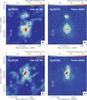 |
Fig. 12 Comparison of the ALMA continuum emission maps (left panels, see also Figs. 4 and 5) to synthetic images at 242 GHz (right panels) of the 3D radiative transfer model presented in Schmiedeke et al. (2016). The top panels show the emission toward Sgr B2(N), while the bottom panels show the emission toward Sgr B2(M). The synthetic images have been post-processed to the same uv sampling of the actual ALMA observations, adding thermal noise corresponding to a precipitable water vapor of 0.7 mm. |
 |
Fig. 13 Comparison of the spectral index map derived from the ALMA continuum measurements in the range 211-275 GHz (left panels, see also Fig. 7) to the spectral index map obtained from the 3D radiative transfer model (right panels). The top panels show the emission toward Sgr B2(N), while the bottom panels show the emission toward Sgr B2(M). |
Finally, in Table 4 we present a summary of the properties of the continuum sources detected in the ALMA images. The second column indicates the most probable origin of the continuum emission at 1.3 mm from the analysis presented in Sects. 4.1 and 4.2. As a complement, in Fig. A.3 we present a finding chart of both Sgr B2(N) and Sgr B2(M) where we indicate the positions of already known Hii regions (yellow circles) and (sub)millimeter continuum sources (red crosses). We consider the emission to be dominated by ionized gas thermal emission, if the flux at 40 GHz (from VLA) is within a factor of 3 with respect to the flux at 242 GHz (from ALMA). If the source is associated with 40 GHz continuum, but its contribution is less than a factor of 3 with respect to the flux at 1.3 mm, we catalog the source as a mixture of dust and ionized gas. All the other sources seem to be dust dominated. The chemical richness is evaluated from the number of lines per GHz and the fraction of line luminosity (see last columns in Table 3). Those sources with a fraction of the line luminosity above 15% and more than 20 lines per GHz are considered to be chemically rich. If only one of the two criteria is fulfilled, the source is considered potentially chemically rich. In the last column of Table 4 we list the association of the ALMA continuum sources with other sources detected at different frequencies (mainly centimeter and millimeter). Even the smaller sources found in Sgr B2(N) and Sgr B2(M) showing a rich chemistry would be considered quite respectable if they were located far from the main, central hot molecular cores. For example, sources like AM09 and AM10 in Sgr B2(M) or AN05 and AN06 in Sgr B2(N) have masses of a few hundred M⊙, which is similar to the masses and chemical richness of well-known hot molecular cores like Orion KL, G31.41+0.31, or G29.96−0.02 (e.g., Wyrowski et al. 1999; Schilke et al. 2001; Cesaroni et al. 2011). Therefore, both Sgr B2(N) and Sgr B2(M) harbor rich clusters of hot molecular cores.
4.4. Comparison with 3D-radiative transfer models
In this section we compare the ALMA continuum maps with predictions from a 3D radiative transfer model. Schmiedeke et al. (2016) used VLA 40 GHz data (Rolffs et al. 2011) and SMA 345 GHz data (Qin et al. 2011), together with Herschel-HIFI (Bergin et al. 2010), Herschel-HiGAL (Molinari et al. 2010), and APEX-ATLASGAL (Schuller et al. 2009) observations of Sgr B2, to generate a 3D model of the structure of the whole region, from 100 au to 45 pc scales. The model contains the dust cores previously detected in the SMA images and the Hii regions reported by Gaume et al. (1995), De Pree et al. (1998, 2014), and Rolffs et al. (2011). The model reproduces the intensity and structure of Sgr B2(N) and Sgr B2(M) as observed with the SMA and the VLA, and it is also able to create synthetic maps for any frequency. In Fig. 12 we compare the continuum map obtained with ALMA, to the model prediction at a frequency of 242 GHz. The synthetic images produced with the model are post-processed to the same uv sampling of the ALMA observations and we added thermal noise corresponding to 0.7 mm of precipitable water vapor. The general structure of the model agrees with the structure seen in the ALMA observations. However, there are some differences that deserve to be discussed.
Summary of the nature and chemical contents.
First, the model does not include the new sources detected in the ALMA continuum images. This results in some structures missing in the model image, such as the filamentary extension to the west of Sgr B2(N). Similarly, the northern component of Sgr B2(N) was catalogued as a single source in the SMA observations, while the ALMA images indicate a possible fragmentation in three different dense cores. This results in a disagreement in the extension and orientation of the emission between the observations and the model. The structure of the model of Sgr B2(M) is more similar to the actual observations, although the new sources are not included in the model, such as the sources to the southeast, which are located at the edge of the primary beam of the SMA observations. Second, the model considers the dense cores to have a plummer-like density structure. This implies that more complex structures, such as the filamentary structures seen toward the center of Sgr B2(N), are not reproduced in the model. Finally, the intensity scale in the model image is off with respect to the observations by a factor of 1.5 as the observations are stronger than the model prediction. This can be related to uncertainties in the flux calibration of the SMA image used to create the model, which can be of up to 20–30%. The uncertainty in the flux calibration of the ALMA observations is also about 20%. Moreover, the dust mass opacity coefficient and the dust emissivity index were not well constrained in the creation of the 3D model, since only one high-angular resolution image at (sub)millimeter wavelengths was available (i.e., the SMA sub-arcsecond observations of Qin et al. 2011). This can result in the flux offset seen at the frequencies observed with ALMA.
In Fig. 13 we compare the spectral index maps derived from the ALMA observations (see Sect. 4.1) with spectral index maps built from the output of the 3D model. The synthetic spectral index maps were created following the same approach as for the ALMA observations. A number of continuum images were produced from the model at the central frequencies of the ALMA spectral windows, and post-processed with the uv sampling of the ALMA observations. Afterwards, we compute linear fits to the flux on a pixel-to-pixel basis to create the spectral index map. The synthetic spectral index maps have the same general properties as the observed spectral index maps as the brightest sources have spectral indices around + 2 and likely trace optically thick dust emission, and the outskirts are more optically thin. The model is also able to reproduce the flat spectral indices observed toward the sources AN10 in Sgr B2(N) and AM08 in Sgr B2(M), likely associated with ionized gas (see Sect. 4.2 and Table 4).
In summary, most of the discrepancies found between the model and the observations are caused by a lack of information when the 3D structure model was created, i.e., lack of observations at other frequencies to better constrain the structure, number of sources, and dependence of flux with frequency. These issues will be solved in the near future thanks to a number of ongoing observational projects aimed at studying Sgr B2 with an angular resolution of  at frequencies of 5 GHz and 10 GHz (using the VLA) and at 100 GHz, 150 GHz and 180 GHz (using ALMA). These observations together with the presented ALMA band 6 observations will permit us to better characterize the physical properties of the different sources found in Sgr B2 and to improve the current 3D model of the region.
5. Summary
We have observed the Sgr B2(M) and Sgr B2(N) high-mass star-forming regions with ALMA in the frequency range 211–275 GHz, i.e., covering the entire band 6 of ALMA in the spectral scan mode. The observations were conducted in one of the most extended configurations available in cycle 2, resulting in a synthesized beam that varies from to across the whole band. Our main results can be summarized as follows:
-
We applied a new continuum determination method to the ALMA Sgr B2 data to produce continuum images of both Sgr B2(N) and Sgr B2(M). The final images have an angular resolution of
(or 3400 au) and a rms noise level of about 8 mJy beam-1. We produced continuum images at different frequencies, which permits us to characterize the spectral index and study the nature of the continuum sources. -
We identified 20 sources in Sgr B2(N) and 27 sources in Sgr B2(M). The number of detected sources in the central 10′′ of each source is increased with respect to previous SMA observations at 345 GHz (12 against 2 sources in Sgr B2(N) and 18 against 12 sources in Sgr B2(M)). This suggests that the ALMA observations at 1.3 mm are sensitive not only to the dust cores detected with the SMA but to a different population of objects (e.g., fainter dust condensations and sources with ionized gas emission). As found in previous SMA observations, Sgr B2(M) is highly fragmented, while Sgr B2(N) consists of one major source surrounded by a few fainter objects. The ALMA maps reveal filamentary-like structures associated with the main core (AN01) in Sgr B2(N), that converge toward the center, which is suggestive of accretion channels transferring mass from the outskirts to the center.
-
We derived spectral indices for each source using the continuum images produced across all the ALMA band 6. We found that the sources with higher continuum intensities show spectral indices in the range 2–4 that is typical of dust continuum emission. Fainter sources have spectral indices that vary from negative or flat (typical of Hii regions) to positive spectral indices (characteristic of optically thick Hii regions or dust cores). The presence of ionized gas emission at the frequencies 211–275 GHz is confirmed when comparing with VLA 40 GHz continuum images. Spectral index maps show that the dense, dust-dominated cores are optically thick toward the center and optically thin in the outskirts.
-
We derived physical properties of the dust and ionized gas for the sources identified in the ALMA images. The gas and dust mass of the sources range from a few to a few 1000 M⊙, the H2 volume density ranges from 107 to 109 cm-3, and the H2 column densities range from 1024 to 1026 cm-2. While Sgr B2(M) has most of the mass distributed among different sources, in Sgr B2(N) most of the mass (about 73%) is contained in one single core (AN01), corresponding to about 9000 M⊙ in a 0.05 pc size structure. The cumulative mass function (or core mass functon) suggests a lack of low-mass dense cores, similar to what has been found in other regions forming high-mass stars. The high densities found in Sgr B2(N) and Sgr B2(M) of about 105–107 M⊙ pc-3 are one to two orders of magnitude larger than the stellar densities found in super star clusters, suggesting Sgr B2 has the potential to form a super star cluster.
-
We statistically characterized the chemical content of the sources by studying the number of lines per GHz and the percentage of luminosity contained in the lines with respect to the total luminosity (line plus continuum). In general, Sgr B2(N) is chemically richer than Sgr B2(M). The chemically richest sources have about 100 lines per GHz and the fraction of luminosity contained in spectral lines is about 35% for the most rich sources and in the range 10–20% for the others. We find a correlation between the chemical richness and the mass (and density of the cores) that may suggest that less massive objects appear less chemically rich because of sensitivity limitations. A more accurate analysis of the chemical content will be presented in forthcoming papers. Sgr B2(N) and Sgr B2(M) harbor clusters of massive and chemically rich hot molecular cores, similar to other well-known hot cores in the Galactic disk, such as Orion KL or G31.41+0.31.
-
Finally, we compared the continuum images and spectral index maps obtained from the ALMA observations with predictions from a 3D radiative transfer model that reproduces the structure of Sgr B2 from 45 pc scales down to 100 au scales. The general structure of the model prediction agrees well with the structure seen in the ALMA images. However, there are some discrepancies caused by a lack of information when the 3D model was created, i.e., lack of new sources discovered in the ALMA observations and lack of (sub-arcsecond) observations at different frequencies to better constrain the dependence of flux on frequency. The dataset presented here, together with ongoing (sub-arcsecond) observational projects in the frequency range from 5 GHz to 200 GHz, will help to better constrain the 3D structure of Sgr B2 and derive more accurate physical parameters for the sources around the Sgr B2(N) and Sgr B2(M) star-forming regions.
The Common Astronomy Software Applications (CASA) software can be downloaded at http://casa.nrao.edu
These two sources are also identified in the sub-arcsecond SMA observations of Qin et al. (2011), with names SMA1 and SMA2 for the brightest core and the core located 5′′ to the north, respectively. These sources have also been named N1 and N2 (e.g., Müller et al. 2016).
Acknowledgments
This work was supported by Deutsche Forschungsgemeinschaft through grant SFB 956 (subproject A6). S.-L.Q. is supported by NSFC under grant No. 11373026, and Top Talents Program of Yunnan Province (2015HA030). This paper makes use of the following ALMA data: ADS/JAO.ALMA#2013.1.00332.S. ALMA is a partnership of ESO (representing its member states), NSF (USA) and NINS (Japan), together with NRC (Canada) and NSC and ASIAA (Taiwan), in cooperation with the Republic of Chile. The Joint ALMA Observatory is operated by ESO, AUI/NRAO and NAOJ.
References
- ALMA Partnership, Fomalont, E. B., Vlahakis, C., et al. 2015, ApJ, 808, L1 [Google Scholar]
- Antonucci, R. R. J., & Ulvestad, J. S. 1985, ApJ, 294, 158 [NASA ADS] [CrossRef] [Google Scholar]
- Belloche, A., Müller, H. S. P., Menten, K. M., Schilke, P., & Comito, C. 2013, A&A, 559, A47 [NASA ADS] [CrossRef] [EDP Sciences] [Google Scholar]
- Belloche, A., Garrod, R. T., Müller, H. S. P., & Menten, K. M. 2014, Science, 345, 1584 [NASA ADS] [CrossRef] [PubMed] [Google Scholar]
- Belloche, A., Müller, H. S. P., Garrod, R. T., & Menten, K. M. 2016, A&A, 587, A91 [NASA ADS] [CrossRef] [EDP Sciences] [Google Scholar]
- Bergin, E. A., Phillips, T. G., Comito, C., et al. 2010, A&A, 521, L20 [NASA ADS] [CrossRef] [EDP Sciences] [Google Scholar]
- Bonfand, M., Belloche, A., Menten, K. M., Garrod, R. T., & Mueller, H. S. P. 2017, A&A, in press, DOI: 10.1051/0004-6361/201730648 [Google Scholar]
- Briggs, D. 1995, Ph.D. Thesis, New Mexico Inst. of Mining and Technology [Google Scholar]
- Cesaroni, R., Beltrán, M. T., Zhang, Q., Beuther, H., & Fallscheer, C. 2011, A&A, 533, A73 [NASA ADS] [CrossRef] [EDP Sciences] [Google Scholar]
- Corby, J. F., Jones, P. A., Cunningham, M. R., et al. 2015, MNRAS, 452, 3969 [NASA ADS] [CrossRef] [Google Scholar]
- De Pree, C. G., Goss, W. M., & Gaume, R. A. 1998, ApJ, 500, 847 [NASA ADS] [CrossRef] [Google Scholar]
- De Pree, C. G., Peters, T., Mac Low, M.-M., et al. 2014, ApJ, 781, L36 [NASA ADS] [CrossRef] [Google Scholar]
- Friedel, D. N., Xu, L., Looney, L., et al. 2015, Amer. Astron. Soc. Meet. Abstr., 225, 336.35 [Google Scholar]
- Gaume, R. A., Claussen, M. J., de Pree, C. G., Goss, W. M., & Mehringer, D. M. 1995, ApJ, 449, 663 [NASA ADS] [CrossRef] [Google Scholar]
- Ginsburg, A., Goss, W. M., Goddi, C., et al. 2016, A&A, 595, A27 [NASA ADS] [CrossRef] [EDP Sciences] [Google Scholar]
- Goldsmith, P. F., Lis, D. C., Hills, R., & Lasenby, J. 1990, ApJ, 350, 186 [NASA ADS] [CrossRef] [Google Scholar]
- Hildebrand, R. H. 1983, Quant. J. Roy. Astron. Soc., 24, 267 [Google Scholar]
- Hollis, J. M., Pedelty, J. A., Boboltz, D. A., et al. 2003, ApJ, 596, L235 [NASA ADS] [CrossRef] [Google Scholar]
- Kurtz, S. 2005, Massive Star Birth: A Crossroads of Astrophysics, 227, 111 [Google Scholar]
- Juvela, M., Demyk, K., Doi, Y., et al. 2015, A&A, 584, A94 [NASA ADS] [CrossRef] [EDP Sciences] [Google Scholar]
- Lis, D. C., & Goldsmith, P. F. 1989, ApJ, 337, 704 [NASA ADS] [CrossRef] [Google Scholar]
- Liu, H. B., Galván-Madrid, R., Jiménez-Serra, I., et al. 2015, ApJ, 804, 37 [NASA ADS] [CrossRef] [Google Scholar]
- McGuire, B. A., Carroll, P. B., & Remijan, A. J. 2013, ArXiv e-prints [arXiv:1306.0927] [Google Scholar]
- Molinari, S., Swinyard, B., Bally, J., et al. 2010, A&A, 518, L100 [NASA ADS] [CrossRef] [EDP Sciences] [Google Scholar]
- Möller, T., Endres, C., & Schilke, P. 2017, A&A, 598, A7 [NASA ADS] [CrossRef] [EDP Sciences] [Google Scholar]
- Müller, H. S. P., Belloche, A., Xu, L.-H., et al. 2016, A&A, 587, A92 [NASA ADS] [CrossRef] [EDP Sciences] [Google Scholar]
- Neill, J. L., Bergin, E. A., Lis, D. C., et al. 2014, ApJ, 789, 8 [NASA ADS] [CrossRef] [Google Scholar]
- Nummelin, A., Bergman, P., Hjalmarson, Å., et al. 1998, ApJS, 117, 427 [NASA ADS] [CrossRef] [Google Scholar]
- Ossenkopf, V., & Henning, T. 1994, A&A, 291, 943 [NASA ADS] [Google Scholar]
- Portegies Zwart, S. F., McMillan, S. L. W., & Gieles, M. 2010, ARA&A, 48, 431 [NASA ADS] [CrossRef] [Google Scholar]
- Qin, S.-L., Zhao, J.-H., Moran, J. M., et al. 2008, ApJ, 677, 353 [NASA ADS] [CrossRef] [Google Scholar]
- Qin, S.-L., Schilke, P., Rolffs, R., et al. 2011, A&A, 530, L9 [NASA ADS] [CrossRef] [EDP Sciences] [Google Scholar]
- Reach, W. T., Heiles, C., & Bernard, J.-P. 2015, ApJ, 811, 118 [NASA ADS] [CrossRef] [Google Scholar]
- Reid, M. J., Menten, K. M., Brunthaler, A., et al. 2014, ApJ, 783, 130 [Google Scholar]
- Rolffs, R., Schilke, P., Wyrowski, F., et al. 2011, A&A, 529, A76 [NASA ADS] [CrossRef] [EDP Sciences] [Google Scholar]
- Sánchez-Monge, Á., Beltrán, M. T., Cesaroni, R., et al. 2013a, A&A, 550, A21 [NASA ADS] [CrossRef] [EDP Sciences] [Google Scholar]
- Sánchez-Monge, Á., Kurtz, S., Palau, A., et al. 2013b, ApJ, 766, 114 [NASA ADS] [CrossRef] [Google Scholar]
- Sánchez-Monge, Á., Schilke, P., Ginsburg, A., et al. 2017, A&A, submitted [Google Scholar]
- Schilke, P., Benford, D. J., Hunter, T. R., Lis, D. C., & Phillips, T. G. 2001, ApJS, 132, 281 [NASA ADS] [CrossRef] [Google Scholar]
- Schilke, P., Neufeld, D. A., Müller, H. S. P., et al. 2014, A&A, 566, A29 [NASA ADS] [CrossRef] [EDP Sciences] [Google Scholar]
- Schmiedeke, A., Schilke, P., Möller, T., et al. 2016, A&A, 588, A143 [NASA ADS] [CrossRef] [EDP Sciences] [Google Scholar]
- Schnee, S., Enoch, M., Noriega-Crespo, A., et al. 2010, ApJ, 708, 127 [Google Scholar]
- Schnee, S., Mason, B., Di Francesco, J., et al. 2014, MNRAS, 444, 2303 [NASA ADS] [CrossRef] [Google Scholar]
- Schuller, F., Menten, K. M., Contreras, Y., et al. 2009, A&A, 504, 415 [NASA ADS] [CrossRef] [EDP Sciences] [Google Scholar]
- Snyder, L. E., Kuan, Y.-J., & Miao, Y. 1994, The Structure and Content of Molecular Clouds, 439, 187 [NASA ADS] [CrossRef] [Google Scholar]
- Wyrowski, F., Schilke, P., & Walmsley, C. M. 1999, A&A, 341, 882 [NASA ADS] [Google Scholar]
- Zhang, Q., Wang, K., Lu, X., & Jiménez-Serra, I. 2015, ApJ, 804, 141 [NASA ADS] [CrossRef] [Google Scholar]
Appendix A: Extra figures
In Fig. A.1 we show the continuum maps created to determine the sources in both Sgr B2(N) and Sgr B2(M) as described in Sect. 3.2. These maps were used to search for common structures considered to be real emission and structures that only appear in few maps considered to be artifacts produced during the cleaning and continuum determination processes. The first four panels correspond to the continuum images produced after averaging the continuum maps of the spectral windows contained in each of the frequency blocks shown in Fig. 1. The central frequencies are 220 GHz, 235 GHz, 250 GHz, and 265 GHz. The last two panels show the averaged continuum images for the low-frequency tuning centered at 227.5 GHz and the high-frequency tuning centered at 256.6 GHz. Figure A.2 shows the noise level emission, or error in the continuum determination, of the continuum emission for the maps shown in Fig. A.1. The error is obtained from the cSCM method in STATCONT, as described in Sánchez-Monge et al. (2017, see also Sect. 3.1). The central pixels, associated with complex spectra have larger uncertainties than those pixels associated with just noise or faint emission.
In Fig. A.3 we show the ALMA continumm emission maps of Sgr B2(N) and Sgr B2(M), and overlay the size and position of the known Hii regions (see Schmiedeke et al. 2016 and references therein) and the position of the sub-millimeter continuum sources identified by Qin et al. (2011) with the SMA at 345 GHz.
 |
Fig. A.1 Continuum emission maps for Sgr B2(N) (top panels) and Sgr B2(M) (bottom panels) obtained after averaging different continuum emission maps. The central frequencies are indicated in each panel. The color bar is units of Jy beam-1, with a round synthesized beam of 0.̋4. See more details in Sect. 3.2 and Appendix A. |
 |
Fig. A.2 Noise maps for Sgr B2(N) (top panels) and Sgr B2(M) (bottom panels) obtained from the determination of the continuum level, and after averaging the different noise maps produced for each spectral window. The central frequencies are indicated in each panel. The color bar is units of mJy beam-1, with a round synthesized beam of 0.̋4. See more details in Sect. 3.2 and Appendix A. |
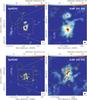 |
Fig. A.3 Finding charts of the different known continuum sources in Sgr B2(N) (top panels) and Sgr B2(M) (bottom panels). The yellow circles indicate well-known Hii regions (see Schmiedeke et al. 2016 and references therein), while the red crosses show the position of the sub-millimeter sources identified by Qin et al. (2011). The association of the ALMA sources with the Hii regions and sub-millimeter sources is summarized in Table 4. |
Appendix B: Continuum flux and chemical content of Sgr B2 sources
Tables B.1 and B.2 list the fluxes derived for each source identified in both Sgr B2(N) and Sgr B2(M), for all the continuum maps created across the band 6 of ALMA (from 211 GHz to 275 GHz). The fluxes of each source are listed in different columns, while each row contains the values for a given continuum image or frequency. The frequencies listed in the first column indicate the central frequency used during the determination of the continuum level emission. The first block of rows contains the fluxes for the individual spectral windows (see Fig. 1). The last blocks of rows contain the fluxes for the extra continuum images created to identify the ALMA 1.3 mm continuum sources (see Sect. 3.2 for more details).
Figures B.1 and B.2 show a summary of the mm-SED and chemical content for each identified source in Sgr B22(N) and Sgr B2(M), respectively. The left panel shows the mm-SED with the measured fluxes and 1σ errors shown in gray. The linear fit and value of the spectral index (α) are shown in black. The right panel shows a portion of the spectral line survey for each source. The spectra were obtained after averaging the emission inside the 3σ polygon defined to measure the continuum fluxes. The brightness temperature scale was fixed to show the differences between sources better.
Sgr B2(N) fluxes and errors for all the continuum maps.
Sgr B2(M) fluxes and errors for all the continuum maps.
 |
Fig. B.1 Left: Sgr B2(N) spectral density distributions for the ALMA continuum sources shown in Fig. 4 and listed in Table 1. Each gray dot corresponds to the integrated flux over the area of each source, when the flux is above the 3σ detection threshold. The fluxes at different frequencies are listed in Table B.1. The solid line is a linear fit to the data, with α corresponding to the spectral index (Sν ∝ να). Right: averaged spectrum over the 3σ-level polygon that defines the source, corresponding to the frequency range 211–213 GHz. The intensity scale of the top panel is adjusted to show the line features better, while the scale in the bottom panel was fixed for all the sources to show the relative brightness of the spectral lines between sources. |
 |
Fig. B.1 continued. |
 |
Fig. B.1 continued. |
 |
Fig. B.1 continued. |
 |
Fig. B.1 continued. |
 |
Fig. B.2 Left: Sgr B2(M) spectral density distributions for the ALMA continuum sources shown in Fig. 5 and listed in Table 1. Each gray dot corresponds to the integrated flux over the area of each source, when the flux is above the 3σ detection threshold. The fluxes at different frequencies are listed in Table B.2. The solid line is a linear fit to the data, with α corresponding to the spectral index (Sν ∝ να). Right: averaged spectrum over the 3σ-level polygon that defines the source, corresponding to the frequency range 211–213 GHz. Note that the intensity scale of the top panel is adjusted to better show the line features, while the scale in the bottom panel has been fixed for all the sources to show the relative brightness of the spectral lines between sources. |
 |
Fig. B.2 continued. |
 |
Fig. B.2 continued. |
 |
Fig. B.2 continued. |
 |
Fig. B.2 continued. |
 |
Fig. B.2 continued. |
All Tables
Dust emission, ionized gas, and molecular properties of the ALMA continuum sources in Sgr B2.
All Figures
|
Fig. 1 Sketch of the setup of the ALMA correlator during the spectral scan observations in the ALMA band 6. The observations are divided into two frequency ranges: low frequencies from 211 to 246 GHz and high frequencies from 240 to 275 GHz. Each frequency tuning is depicted with a different color, while the different boxes refer to the four spectral windows per tuning. The number of the spectral windows, as given in the ALMA observations, are given on top of each box. The gray line shows the transmission of the atmosphere at the ALMA site with a precipitable water vapor of 0.7 mm. |
| In the text | |
|
Fig. 2 Continuum emission maps for Sgr B2-N (left column) and Sgr B2-M (right column) produced using STATCONT as described in Sect. 3.1 for four different spectral windows, corresponding to the central frequencies 213.875 GHz, 235.500 GHz, 256.078 GHz, and 273.953 GHz from top to bottom. The synthesized beam is |
| In the text | |
|
Fig. 3 Variation of the intensity (in Jy beam-1) with frequency (in GHz) for four pixels in the Sgr B2(N) (open circles) and Sgr B2(M) (filled circles) regions. The vertical lines correspond to the error in the determination of the continuum level as computed by STATCONT (see Sect. 3.1). The intensity is extracted for each continuum map created at different frequencies (see Sect. 3.1). The numbers in parenthesis next to the name of the sources refer to the number of the sources as listed in Tables 1 and 2 (see also Sect. 3.2). The spectral index (α, defined as I ∝ να) is indicated for each source. The intensity of source Sgr B2(M) AM15 is manually shifted by +0.3 Jy beam-1. |
| In the text | |
|
Fig. 4 ALMA 242 GHz continuum emission toward Sgr B2(N). The right panel shows a close-up view of the central 0.56 pc. The identified sources are indicated with crosses. The number indicates the source ID as listed in Table 2. The synthesized beam is |
| In the text | |
|
Fig. 5 ALMA 242 GHz continuum emission toward Sgr B2(M). The right panel shows a close-up view of the central 0.56 pc. The identified sources are indicated with crosses. The number indicates the source ID as listed in Table 2. The synthesized beam is |
| In the text | |
|
Fig. 6 Spectral index within the ALMA frequency coverage (from 211 GHz to 275 GHz) as a function of the intensity peak of the continuum emission at 242 GHz (see Tables 1 and 2). Filled circles depict the continuum sources found in Sgr B2(N), while open circles correspond to the sources identified in Sgr B2(M). The red area shows the spectral index regime expected for dust sources (from + 2 for optically thick dust emission to + 4 for optically thin dust emission). The light blue area shows the regime of spectral indices for ionized gas sources, ranging from − 0.1 for optically thin, homogeneous Hii regions (also indicated with a dark blue dashed line) to + 2 for optically thick sources. The vertical and horizontal lines show 1σ error bars for the spectral index and intensity peak. |
| In the text | |
|
Fig. 7 Spectral index map from the ALMA continuum measurements from 211 GHz to 275 GHz (see Sect. 4.1) for Sgr B2(N) (left panel) and Sgr B2(M) (right panel). The ALMA 1.3 mm (242 GHz) continuum emission, as shown in Figs. 4 and 5, is orvelaid in gray contours. The synthesized beam is |
| In the text | |
|
Fig. 8 Top panels: Sgr B2(N) ALMA continuum emission image at 242 GHz compared to the VLA 40 GHz continuum emission in contours (left panel; from Rolffs et al. 2011, and convolved to |
| In the text | |
|
Fig. 9 Distributions of a) dust and gas mass; b) H2 volume density; c) H2 column density; d) electron density; e) ionized gas mass; f) number of ionizing photons or Lyman contiuum; g) number of lines per GHz; h) line luminosity; and i) percentage of line luminosity with respect to the total luminosity (line plus continuum) for the ALMA continuum sources detected toward Sgr B2 (see Table 3). The gray filled area shows the distribution of all the sources, while the blue solid line corresponds to the sources in Sgr B2(N) and the red solid line corresponds to the sources in Sgr B2(M). The black dashed line in the middle panels is derived from the physical parameters of all the Hii regions detected in the Sgr B2 star-forming complex (see Appendix B of Schmiedeke et al. 2016). All the KDE distributions are normalized to their maximum value to better show differences between the different regions. |
| In the text | |
|
Fig. 10 Cumulative mass function of the sources identified toward Sgr B2. The blue and red dotted lines correspond to the sources identified in Sgr B2(N) and Sgr B2(M), respectively. The dashed line shows the cumulative mass function of the fragments identified in the massive infrared dark cloud G28.34 by Zhang et al. (2015), scaled by a factor of 10 in mass. The dot-dashed line indicates the slope of the Salpeter initial mass funciton. The vertical gray line indicates the 5σ mass sensitivity limit of 7.9 M⊙ for a temperature of 100 K. |
| In the text | |
|
Fig. 11 Scatter plots showing the relation between the properties derived from the dust emission. Spectral index determined in the range 211–275 GHz (top panels), H2 column density (middle panels), and dust and gas mass (bottom panels) with respect to the percentage of line luminosity over the total luminosity (left column) and the number of lines per GHz (right column). Filled circles correspond to the sources identified in Sgr B2(N), while open circles show the sources found in Sgr B2(M). Gray symbols and stars indicate those ALMA continuum sources associated with VLA 40 GHz continuum emission. The solid lines in four panels correspond to linear fits to the black symbols in each panel (see more details in Sect. 4.3). |
| In the text | |
|
Fig. 12 Comparison of the ALMA continuum emission maps (left panels, see also Figs. 4 and 5) to synthetic images at 242 GHz (right panels) of the 3D radiative transfer model presented in Schmiedeke et al. (2016). The top panels show the emission toward Sgr B2(N), while the bottom panels show the emission toward Sgr B2(M). The synthetic images have been post-processed to the same uv sampling of the actual ALMA observations, adding thermal noise corresponding to a precipitable water vapor of 0.7 mm. |
| In the text | |
|
Fig. 13 Comparison of the spectral index map derived from the ALMA continuum measurements in the range 211-275 GHz (left panels, see also Fig. 7) to the spectral index map obtained from the 3D radiative transfer model (right panels). The top panels show the emission toward Sgr B2(N), while the bottom panels show the emission toward Sgr B2(M). |
| In the text | |
|
Fig. A.1 Continuum emission maps for Sgr B2(N) (top panels) and Sgr B2(M) (bottom panels) obtained after averaging different continuum emission maps. The central frequencies are indicated in each panel. The color bar is units of Jy beam-1, with a round synthesized beam of 0.̋4. See more details in Sect. 3.2 and Appendix A. |
| In the text | |
|
Fig. A.2 Noise maps for Sgr B2(N) (top panels) and Sgr B2(M) (bottom panels) obtained from the determination of the continuum level, and after averaging the different noise maps produced for each spectral window. The central frequencies are indicated in each panel. The color bar is units of mJy beam-1, with a round synthesized beam of 0.̋4. See more details in Sect. 3.2 and Appendix A. |
| In the text | |
|
Fig. A.3 Finding charts of the different known continuum sources in Sgr B2(N) (top panels) and Sgr B2(M) (bottom panels). The yellow circles indicate well-known Hii regions (see Schmiedeke et al. 2016 and references therein), while the red crosses show the position of the sub-millimeter sources identified by Qin et al. (2011). The association of the ALMA sources with the Hii regions and sub-millimeter sources is summarized in Table 4. |
| In the text | |
|
Fig. B.1 Left: Sgr B2(N) spectral density distributions for the ALMA continuum sources shown in Fig. 4 and listed in Table 1. Each gray dot corresponds to the integrated flux over the area of each source, when the flux is above the 3σ detection threshold. The fluxes at different frequencies are listed in Table B.1. The solid line is a linear fit to the data, with α corresponding to the spectral index (Sν ∝ να). Right: averaged spectrum over the 3σ-level polygon that defines the source, corresponding to the frequency range 211–213 GHz. The intensity scale of the top panel is adjusted to show the line features better, while the scale in the bottom panel was fixed for all the sources to show the relative brightness of the spectral lines between sources. |
| In the text | |
|
Fig. B.1 continued. |
| In the text | |
|
Fig. B.1 continued. |
| In the text | |
|
Fig. B.1 continued. |
| In the text | |
|
Fig. B.1 continued. |
| In the text | |
|
Fig. B.2 Left: Sgr B2(M) spectral density distributions for the ALMA continuum sources shown in Fig. 5 and listed in Table 1. Each gray dot corresponds to the integrated flux over the area of each source, when the flux is above the 3σ detection threshold. The fluxes at different frequencies are listed in Table B.2. The solid line is a linear fit to the data, with α corresponding to the spectral index (Sν ∝ να). Right: averaged spectrum over the 3σ-level polygon that defines the source, corresponding to the frequency range 211–213 GHz. Note that the intensity scale of the top panel is adjusted to better show the line features, while the scale in the bottom panel has been fixed for all the sources to show the relative brightness of the spectral lines between sources. |
| In the text | |
|
Fig. B.2 continued. |
| In the text | |
|
Fig. B.2 continued. |
| In the text | |
|
Fig. B.2 continued. |
| In the text | |
|
Fig. B.2 continued. |
| In the text | |
|
Fig. B.2 continued. |
| In the text | |
Current usage metrics show cumulative count of Article Views (full-text article views including HTML views, PDF and ePub downloads, according to the available data) and Abstracts Views on Vision4Press platform.
Data correspond to usage on the plateform after 2015. The current usage metrics is available 48-96 hours after online publication and is updated daily on week days.
Initial download of the metrics may take a while.