| Issue |
A&A
Volume 683, March 2024
|
|
|---|---|---|
| Article Number | A225 | |
| Number of page(s) | 19 | |
| Section | Numerical methods and codes | |
| DOI | https://doi.org/10.1051/0004-6361/202347277 | |
| Published online | 22 March 2024 | |
LeHaMoC: A versatile time-dependent lepto-hadronic modeling code for high-energy astrophysical sources★
1
Department of Physics, National and Kapodistrian University of Athens, University Campus Zografos,
GR 15784,
Athens,
Greece
e-mail: This email address is being protected from spambots. You need JavaScript enabled to view it.
2
Institute of Accelerating Systems & Applications, University Campus Zografos,
Athens,
Greece
Received:
24
June
2023
Accepted:
25
December
2023
Abstract
Context. Recent associations of high-energy neutrinos with active galactic nuclei (AGN) have revived the interest in leptohadronic models of radiation from astrophysical sources. The rapid increase in the amount of acquired multi-messenger data will require fast numerical models that may be applied to large source samples.
Aims. We develop a time-dependent leptohadronic code, LeHaMoC, that offers several notable benefits compared to other existing codes, such as versatility and speed.
Methods. LeHaMoC solves the Fokker-Planck equations of photons and relativistic particles (i.e. electrons, positrons, protons, and neutrinos) produced in a homogeneous magnetized source that may also be expanding. The code utilizes a fully implicit difference scheme that allows fast computation of steady-state and dynamically evolving physical problems.
Results. We first present test cases where we compare the numerical results obtained with LeHaMoC against exact analytical solutions and numerical results computed with ATHEvA, a well-tested code of similar philosophy but a different numerical implementation. We find a good agreement (within 10–30%) with the numerical results obtained with ATHEvA without evidence of systematic differences. We then demonstrate the capabilities of the code through illustrative examples. First, we fit the spectral energy distribution from a jetted AGN in the context of a synchrotron-self Compton model and a proton-synchrotron model using Bayesian inference. Second, we compute the high-energy neutrino signal and the electromagnetic cascade induced by hadronic interactions in the corona of NGC 1068.
Conclusions. LeHaMoC is easily customized to model a variety of high-energy astrophysical sources and has the potential to become a widely utilized tool in multi-messenger astrophysics.
Key words: astroparticle physics / radiation mechanisms: non-thermal / radiative transfer / methods: numerical
Instructions for downloading the code, accessing online documentation, and reproducing applications presented in this paper can be found at https://github.com/mariapetro/LeHaMoC Github repository.
© The Authors 2024
 Open Access article, published by EDP Sciences, under the terms of the Creative Commons Attribution License (https://creativecommons.org/licenses/by/4.0), which permits unrestricted use, distribution, and reproduction in any medium, provided the original work is properly cited.
This article is published in open access under the Subscribe to Open model. This email address is being protected from spambots. You need JavaScript enabled to view it. to support open access publication.
1 Introduction
A wide variety of astrophysical sources, including supernova remnants (SNRs), microquasars, active galactic nuclei (AGN), and gamma-ray bursts (GRBs), display non-thermal emission spectral energy distributions (SEDs). This emission, which depending on the type of the source, may span from radio wavelengths to γ-ray energies, requires the presence of relativistic particles with extended energy distributions. Modeling of the broadband emission has been a widely used method for probing indirectly the physical conditions of these astrophysical accelerators, such as particle density, magnetic field strength, bulk motion speed, and others.
Since the discovery of γ-ray emission from AGN (see the reviews Dermer & Giebels 2016; Madejski & Sikora 2016 and references therein), the production mechanism of such energetic photons has been a matter of debate. Two schools of thought have been developed over the years while trying to explain the emission properties of γ-ray emitting sources. The first one postulates that the broadband emission can be fully attributed to energetic electrons accelerated in the source, with some contribution from secondary electron-positron pairs produced through photon-photon pair production (leptonic models). According to the second school, accelerated protons in the source could also make a significant contribution to the high-energy emission (leptohadronic models), either directly via proton synchrotron radiation (Aharonian 2000; Mücke & Protheroe 2001), or indirectly via the radiation of secondary pairs produced in proton-photon interactions (Mannheim 1993), or via neutral pion decay (Reimer et al. 2005). High-energy neutrinos, produced via the pion decay chain, are a natural outcome of this model class.
The recent discovery by the IceCube Collaboration of high-energy neutrino emission (at a significance of ~4.2σ) associated with the prototype Seyfert II galaxy NGC 1068 (IceCube Collaboration 2022) presents a new set of challenges for understanding the underlying physics of these sources. Notably, the observed GeV γ-ray emission from NGC 1068 is relatively low compared to the neutrino luminosity (IceCube Collaboration 2022), which raises intriguing questions about the mechanisms responsible for this disparity and the potential production sites (see e.g., Murase et al. 2020; Inoue et al. 2022; Eichmann et al. 2022, for different explanations). The other astronomical source that has been associated with a significance larger than ~3σ with IceCube neutrinos is the blazar1 TXS 0506+056 (IceCube Collaboration et al. 2018; IceCube Collaboration 2018). These observations, in addition to the discovery of the diffuse astrophysical neutrino flux by IceCube (IceCube Collaboration 2013), have revived the interest in leptohadronic source models.
Leptohadronic radiative models are intrinsically more complex than leptonic ones. The main radiative processes in the latter model class are synchrotron radiation, inverse Comp-ton scattering, photon-photon pair-production, and relativistic bremsstrahlung (which is relevant for sources with dense ionized gas). In leptohadronic models, one has to take also into account the interactions of relativistic protons with low-energy photons and/or gas. Both processes lead to the production of pions that decay into photons, pairs, and neutrinos. Photons and pairs can then initiate electromagnetic cascades in the source via photon-photon pair production, thus producing more targets for proton-photon interactions. The complexity of leptohadronic models lies in (i) the non-linear coupling of the various particle populations (through the so-called kinetic equations i.e., partial differential equations with respect to time and energy), (ii) the wide range of timescales probed by the physical processes, and (iii) the numerical modeling of the secondary particle production spectra. The adoption of different approaches for the modeling of secondary particle injection may yield 10–30% differences in the numerical results obtained with different radiative transfer codes (Cerruti et al. 2022, and in prep.).
Various radiative transfer codes have been employed to study the complex emission processes and interpret the diverse observational properties of non-thermal emitting sources, including recent neutrino observations (e.g. Dimitrakoudis et al. 2012; Böttcher et al. 2013; Cerruti et al. 2015; Gao et al. 2017; Gasparyan et al. 2022). The rapid increase in multi-messenger observations and modeling of larger and more diverse source samples requires high computation efficiency and code adaptability. In this work, we present LeHaMoC (Lepto-Hadronic Modeling Code), a novel radiative transfer code for non-thermal emitting sources. While LeHaMoC is inspired by the modeling code ATHEvA (Mastichiadis & Kirk 1995; Dimitrakoudis et al. 2012), it offers several new key features: significantly shorter code execution times for steady-state problems due to an implicit finite difference scheme (Chang & Cooper 1970), modeling of expanding sources with varying physical conditions, the inclusion of proton-proton inelastic collisions, and fitting capabilities. Our primary goal is to provide a versatile and efficient numerical code to the community.
This paper is structured as follows. In Sect. 2, we outline the range of processes incorporated into LeHaMoC and describe the methodology employed to solve the kinetic equations for each particle species in the source. In Sect. 3.1, we provide an assessment of the code’s performance and accuracy. In Sect. 3.2, we present indicative cases that are compared against analytical results and numerical results obtained with the well-tested code ATHEvA (Dimitrakoudis et al. 2012). In Sect. 4, we showcase two astrophysical applications of LeHaMoC. Firstly, we fit the SED of a blazar that has been proposed as a potential high-energy neutrino emitter using a Bayesian inference approach. Secondly, we employ LeHaMoC to compute the high-energy neutrino signal and derive the electromagnetic cascade resulting from hadronic interactions within the corona of NGC 1068. By examining these specific cases, we demonstrate the versatility and utility of LeHaMoC in describing different astrophysical sources. Finally, we present the conclusions of this work in Sect. 5.
2 Code description
We consider a scenario in which relativistic charged particles (electrons and/or protons) are injected into a spherical blob that contains a magnetic field and may also adiabatically expand. Charged particles are subject to various physical processes that lead to the production of photons and secondary particles, such as relativistic electron-positron pairs, neutrons, and neutrinos. The processes we consider are
Electron and positron synchrotron radiation (e, syn),
Proton synchrotron radiation (p, syn),
Electron and positron inverse Compton scattering (ics),
Synchrotron self-absorption (ssa),
Photon-photon pair creation (γγ),
Proton-photon pion production (pγ, π),
Proton-photon (Bethe-Heitler) pair production (bh),
Proton-proton collisions (pp),
Adiabatic losses (ad).
All particle species are assumed to be isotropically distributed inside the source and to be fully described by the relevant distribution function Ni at time t, which is a function of the charged particle Lorentz factor γi, or frequency v for photons and neutrinos. We trace the evolution of charged particles and photons inside the source as a function of energy and time by numerically solving a system of coupled integrodifferential (kinetic) equations that are summarized below.
Electrons and positrons,
 (1)
(1)
Protons,
 (2)
(2)
Photons,
 (3)
(3)
Neutrinos,
 (4)
(4)
where we account for the contribution of each flavor separately.
In the equations above  expresses the production rate of particle species i due to the process j, while the terms designated with the subscript in j indicate the injection rate of accelerated particles (primaries) into the source. Similarly, the
  term represents the net loss rate of species i due to the physical process j. We have also introduced τi,esc which is the physical escape timescale of species i from the source. In most cases, this timescale is taken to be a multiple of the source’s light-crossing time tcr = R(t)/c, with R(t) being the radius of the spherical blob. Alternatively, if the escape probability is related to the gyroradius of the particle in the source, τi,esc may depend on the particle energy. We allow for both a time-dependent and energy-dependent escape timescale in our code.
We neglect the neutron component and assume that the decay of pions is instantaneous, so we do not treat them using kinetic equations. Detailed expressions of the operators used in the kinetic equations can be found in Appendix A.
To solve the kinetic equations presented in the previous sections we use the fully implicit difference scheme proposed by Chang & Cooper (1970). The stiff differential equations that arise in the context of astrophysical jets, where the various timescales associated with the physical processes can range by many orders of magnitude, are particularly well-suited for this numerical scheme. The specific implicit numerical scheme involves the discretization of the kinetic equations in time and the Lorentz factor and frequency space. To discretize the kinetic equations in time, we use a time step that is related to the characteristic time scale of the system, which depends on the physical scenario studied. The use of an implicit scheme ensures that the solution at any time step is stable, which is useful since the time scales of different physical processes can vary widely. The discretization in energy is achieved by using a logarithmic energy grid that allows us to accurately capture the behavior of the distribution over a wide range of energies. The energy grid size is a parameter that can be defined by the user. Each discretized equation forms a tridiagonal matrix which we solve using Thomas algorithm (Thomas 1949).
To illustrate how the code works, we demonstrate the discretization into time ti and Lorentz factor γi of the kinetic equation for the electron species (Eq. (1)),
 (5)
(5)
where the coefficients are
 (6)
(6)
 (7)
(7)
 (8)
(8)
where (dγ/dt)p are the energy losses to an electron due to the p process.
3 Code performance and testing
3.1 Code performance
We demonstrate the performance and accuracy of the numerical code through three steady-state leptonic runs. In all cases, electrons are injected in the source with a power-law distribution,  , for γe,max ≥ γ ≥ γe,min. For the adopted parameters, electrons, which are continuously injected with γe ≫ 1, are completely cooled down to γe ≳ 1 (i.e. fast cooling regime) via synchrotron radiation (SYN) or inverse Compton (IC) scattering on a fixed blackbody radiation field. A synchrotron self-Compton scenario (SSC) where electrons are still cooled due to synchrotron losses is also considered. In all tests, we examine the relationship between the Lorentz factor grid resolution with the code execution time and the ratio of the bolometric photon luminosity
  , and the relativistic electron luminosity at injection,
  . In the fast cooling regime, all energy injected into relativis-tic electrons should be radiated away, hence the two luminosities should be the same. The parameters used for the performance test are displayed in Table 1. It is important to note that our code is not parallelized and utilizes a single CPU core for computations. All the tests were performed in 12th Gen Intel® Core™ i5-1235U × 12 processor.
The number of grid points (nppd) directly affects the execution time for all three scenarios. The synchrotron scenario is less impacted because the synchrotron emissivity (see Eq. (A.3)) is a less complicated expression than the inverse Compton scattering emissivity, which involves an integral on the target photon field (see Eq. (A.11)), which may also evolve with time. The top panel of Fig. 1 shows that increasing the number of grid points per logarithmic decade increases the time to run the code for all scenarios. This trend is generally expected as more grid points require the computation of emissivity at each point, resulting in longer execution times. However, the relationship between the number of grid points and execution time is not linear. In the complete synchrotron cooling scenario, the execution time increases more rapidly when nppd ≳ 20. In the complete inverse Compton cooling scenario, the execution time scales quadratically with the number of grid points because the emis-sivity involves the calculation of an integral to the target photon field. The SSC scenario follows the same scaling as the inverse Compton cooling scenario since the computation of the inverse Compton emissivity dominates the execution time.
For a typical choice of nppd = 30, the code requires approximately 10 s to reach a steady state for synchro-Compton scenarios, using a time step dt = R0/c. Shorter running times can be achieved by increasing the time step. We verified that a steady-state solution can be accurately achieved with larger time steps. For example, a time step of 3 R0/c can yield accurate steady-state solutions for an SSC model, thus helping to speed up the code execution time by a factor of ~3. Similar conclusions are expected for steady-state calculations including proton synchrotron radiation. The inclusion of photo-hadronic and pp interactions may raise the computation time to 5–10 min for the default energy resolution (nppd = 20–30).
We also evaluated the accuracy of the newly developed code by analyzing the ratio of the bolometric photon to electron injection luminosity as a function of nppd (see bottom panel of Fig. 1). As electrons are fast cooling due to synchrotron radiation in all three cases, the two luminosities should be the same. The results show that in the synchrotron and SSC scenarios, the luminosity ratio is about 4 for nppd = 3, but then decreases gradually to unity (as it should) as the number of grid points increases. The reason for this is that the increased energy resolution allows for more accurate calculations of integrals over particle distributions.
We also examine how the number of grid points affects the spectral shape of the steady-state electron distribution in a fast-cooling synchrotron scenario. For this purpose, we compare the numerical results for three choices of the energy grid resolution (marked with symbols on the top panel of Fig. 1) against the analytical solution of Inoue & Takahara (1996, see Eq. (2.26) therein). The steady-state electron distributions are displayed in Fig. 2, where we see that higher resolution in the energy grid leads to better agreement with the expected (analytical) solution. The adopted numerical scheme does not accurately produce the location of the cooling break if a sparse energy grid is used. According to Park & Petrosian (1996, see their Eq. (13)) the magnitude of Δγ should be smaller than the typical range of variation of the kinetic equation solution at Lorentz factor γ.
These examples illustrate the competition between accuracy and efficiency. To achieve faster computations, we have to use a coarser energy grid (typically with nppd = 20–30) and introduce a correction factor to ensure energy balance between species. Given that the synchrotron photon field is a common target field for a variety of physical processes (e.g. Compton scattering and photohadronic interactions), we determine the appropriate correction factor by running a synchrotron fast cooling case, before we perform any simulation based on the energy grid selected by the user. The spectrum of the secondaries is not affected by the number of grid points.
Finally, it is worth noting that an extremely high accuracy is not needed for most astrophysical applications since fitting uncertainties are usually the limiting factor. This will become evident later in Sect. 4.1 where we use the code to model the multi-wavelength spectrum of a typical jetted AGN (see also corner plots in Appendix C). Consequently, opting for nppd = 10–20 strikes a balance between precision and computational efficiency.
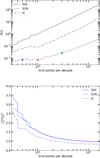 |
Fig. 1 Impact of grid resolution on code execution time and luminosity balance. Top panel: Relation between the code execution time and the number of grid points per logarithmic decade in particle energy for three scenarios of fast cooling electrons described in the text (see Sect. 3.1). Colored triangles indicate three choices for the number of grid points per decade that are used for the results shown in Fig. 2. Bottom panel: Ratio of bolometric photon luminosity to electron injection luminosity versus the number of grid points per logarithmic decade. A ratio of one indicates the expected energy balance between electrons and photons. |
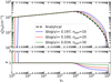 |
Fig. 2 Analytical and numerical comparison of a synchrotron cooling problem and the impact of grid resolution. Top panel: comparison of numerical (solid colored lines) and analytical (dashed black line) solutions for synchrotron cooling electrons in a spherical blob with a constant magnetic field. Each numerical result was calculated using a different number of grid points per decade in the electron Lorentz factor (nppd) as indicated in the legend (see also markers in the top panel of Fig. 1). Bottom panel: Ratio χ between the numerical and the analytical solutions. |
3.2 Tests
We perform comparison tests against the numerical code ATHEvA (Mastichiadis & Kirk 1995; Dimitrakoudis et al. 2012) in order to validate the accuracy and performance of the newly developed numerical code. In the following tests, we adopt nppd = 30, unless stated otherwise. These tests include various radiative processes that are relevant for astrophysical jets, such as synchrotron radiation, inverse Compton scattering, and proton interactions with photons. We also compare our code results with analytical calculations. In the following sections, we will provide a few examples of these comparison tests and discuss the results in detail.
3.2.1 Test 1: A steady-state SSC model with electron cooling
In our first comparison test, we study a synchrotron self-Compton (SSC) model with γγ absorption. The aim is to compare the photon spectrum and the pair injection rate between the ATHEvA code and LeHaMoC. Electrons are injected with a power-law distribution into a spherical blob with radius R0 that contains a magnetic field of strength B0 and are allowed to escape on a timescale equal to the light-crossing time of the source, i.e. tcr = R0/c (for the parameter values see Table 2). We include synchrotron emission and self-absorption, inverse Compton scattering, and γγ pair production.
We present our results in Fig. 3. The upper panel displays the steady-state electron distributions obtained with the two codes. Both solutions exhibit a smooth break due to synchrotron losses. Both numerical codes have the same location for the cooling break in the electron distribution. Beyond the cooling break, the cooled distribution displays the same power-law behavior as expected by synchrotron theory with a power-law index se − 1. In the middle panel, we demonstrate the comoving photon spectra. We observe that the two codes yield comparable results (see ratio plot) over a broad range of frequencies, both before and after applying the correction for energy balance (see Sect. 3.1).
The two codes predict different locations of the synchrotron self-absorption frequency (0.5 in logarithm), which causes a large difference between the two results at frequencies ≲ 100 GHz. This difference can be attributed to the simplified calculation of the synchrotron self-absorption coefficient in ATHEvA (see Eq. (40) in Mastichiadis & Kirk 1995); there it is assumed that the electron emits all the power near the critical synchrotron frequency, while in LeHaMoC we use the full relation of the synchrotron power spectrum instead of this approximation (see Eq. (A.8)). When we implement the delta function approximation we find that the difference is reduced to less than 0.2 in logarithm. Furthermore, we compare the energy spectra of pairs injected via γγ pair production in the bottom panel of Fig. 3. The results are in excellent agreement up to the highest Lorentz factor values.
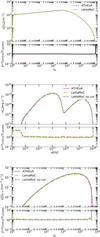 |
Fig. 3 Steady-state SSC model computed using ATHEvA and LeHaMoC codes. We show a comparison of (from top to bottom): the steady-state electron spectra, photon spectra, and production rate of pairs due to γγ absorption. The bottom panel of each plot shows the ratio χ of the spectra computed with ATHEvA and LeHaMoC. All displayed spectra are measured in the comoving frame of the blob. The parameters used for this test can be found in Table 2 under the column Test 1. |
3.2.2 Test 2: Production rates of secondaries in proton-photon interactions with extended energy distributions
We consider next a generic case for proton-photon interactions where relativistic protons interact with a power-law target photon field. This choice is particularly relevant for astrophysical applications since power-law photon fields are expected to arise from non-thermal emission processes such as synchrotron radiation, and inverse Compton scattering. We are interested in comparing the injection spectra of secondaries produced via Bethe-Heitler and photo-pion production processes on a fixed target photon field. Therefore, we only account for the output of the emissivity functions as described in Appendix A and we neglect all emission produced by the secondaries. We also note that protons do not cool via photo-hadronic interactions due to the low target photon density.
The numerical results obtained with the two codes are shown in Fig. 4. Starting from the top left figure, we find good agreement in the π0 decay γ-ray emissivity computed with the two codes, as indicated by the ratio χ in the lower panel; this remains close to unity over a large range of energies, except close to the peak of the spectrum where the difference becomes about 1.4. The pair production spectra from pion decays have a very good agreement (top right panel). The all-flavor neutrino spectra (bottom left panel) have very similar shapes (the ratio is flat across a wide range of energies). Finally, the spectra of Bethe-Heitler pairs are displayed on the bottom right panel. The spectral shapes up to γe ~ 1010 are similar, and there is good agreement in the maximum injected energy (which corresponds to the peak of the spectrum). Nonetheless, the spectrum obtained with ATHEvA appears to be shifted toward higher Lorentz factors by a factor of ~l.5. The sharp cutoff of the spectrum at γe ~ 1010 computed with ATHEvA is artificial because the code considers interaction energies up to 104 above the threshold.
3.2.3 Test 3: A time-dependent adiabatic expansion leptonic model
We aim to compare the numerical solutions obtained with LeHaMoC with the exact analytical solution of the electron kinetic equation in a time-dependent problem that has no steady-state solution. The primary objective is to investigate the ability of the code to solve time-dependent problems and describe the particle distribution evolution with time.
For this purpose, we assume an expanding blob where electrons are injected once at the beginning of the simulation with a power-law distribution of slope se and are left to cool only via adiabatic losses. The blob has an initial radius R0 and expands with a constant velocity Vexp. The magnetic field B0 is considered constant throughout the simulation. Under these assumptions, we can obtain an analytical solution for the evolution of the electron distribution that reads (Kardashev 1962),
 (9)
(9)
 (10)
(10)
where β0 = Vexp/R0 and Θ(y) is the Heavyside function. Moreover, K is a normalization constant, γe,min and γe,max are the minimum and maximum Lorentz factor of the electron distribution at time t, while γe,min,0 and γe,max,0 are the minimum and maximum Lorentz factors at the moment of injection.
Figure 5 shows six snapshots of the particle distribution computed analytically using Eq. (10) (solid lines) and numerically with LeHaMoC. To highlight the impact of the time step dt on the numerical solutions, we performed runs with different choices (see inset legend). The numerical solution captures the decrease of γe,min and γe,max over time due to the adiabatic losses and matches well with the analytical solution in normalization as long as dt ≤ R0/c = tcr,0. In general, choices of dt > tcr,0 lead to diffusion of the numerical solution and do not capture the shape of the distribution with precision.
To further test the accuracy and reliability of our code, we investigate the conservation of electron number throughout the simulation for the numerical results of different time steps. Since electrons are not allowed to escape the system, the total of the electrons, Ne,tot(t) = V(t) ∫ ne(γe, t) dγe, should remain constant over time.
We find that Ne,tot remains constant for all values of dt as long as the integration is performed over a wide range of Lorentz factors (see black lines in Fig. 6). If, however, the integration is limited between the analytically expected γe,min(t) and γe,max(t), we find particle conservation for dt < R0 /c as demonstrated by the blue lines in Fig. 6. We further comment on the impact of dt on the numerical solution of dynamically involving systems through another illustrative example in Appendix B.
By utilizing the analytical solution given by Eq. (10) for an expanding blob subject to adiabatic losses, we can also determine the evolution of the synchrotron-self absorption frequency vssa over time, assuming that synchrotron radiation is the only emission mechanism for electrons (see also Boula & Mastichiadis 2022, for leptonic models with expansion). We find that
 (11)
(11)
We compare the numerical results of vssa2 with the analytical scaling relation in Fig. 7. The solid line has the same slope as the one predicted analytically for β0t ≫ 1, while the numerical results for different time steps are depicted with dashed, solid, and dashed-dotted lines. We observe that for time steps dt ≤ tcr,0, the evolution of numerically derived vssa follows the expected time dependency at late times. However, for dt > tcr,0, the numerical evolution of vssa with time is slower than predicted (see difference in slopes).
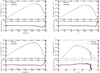 |
Fig. 4 Comparison of injection spectra of secondary particles computed using ATHEvA and LeHaMoC for the case of interactions of relativistic protons with a power-law photon field. From top left and in clockwise order: γ-ray spectra from neutral pion decay, pair spectra from charged pion decays, all-flavor neutrino spectra from charged pion decays, and pair spectra from the Bethe-Heitler process. The parameters used for this test can be found in Table 2 under the column Test 2. |
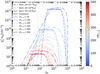 |
Fig. 5 Comparison of numerical (dashed, dotted, and dashed-dotted lines) and analytical (solid lines) solutions for adiabatic cooling electrons in an expanding blob with a constant magnetic field. Each numerical result was calculated using a different time step as indicated in the legend. The parameters used for this test can be found in Table 2 under column Test 3. |
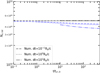 |
Fig. 6 Evolution of the total number of particles Ne with time for the same case shown in Fig. 5. Different types of lines show Ne as derived from the numerical solutions for different choices of the time step (see inset legend). The black lines represent the number of particles calculated by considering all grid points, while the blue lines represent the integration of the particle distribution within the analytically expected range of Lorentz factors, i.e. γe,min(t) and γe,max(t). For comparison, the analytical solution yields Ne,tot = 4.9 × 1050 electrons. |
3.2.4 Test 4: A steady-state leptohadronic model
Finally, we present a generic steady-state leptohadronic scenario. The objective of this test is to compare the broadband photon and neutrino spectra obtained from ATHEvA and LeHaMoC, considering the inclusion of all physical processes (except for pp collisions, which are not included in ATHEvA). To initiate the simulation we assume that relativistic electrons and protons are injected with a distribution  , for γ ≥ γi,min, into a spherical blob with radius R0 and magnetic field strength B0. Moreover, relativistic pairs are injected in the source through Bethe-Heitler pair production, pion production through proton photon interactions, and pair creation via γγ interactions. Particles and photons are allowed to escape on a timescale equal to the light-crossing time of the source, i.e. tcr = R0/c. The parameter values, which are presented in Table 2, are one of the parameter sets used in the Hadronic Code Comparison Project (Cerruti et al., in prep.) where four radiative transfer codes including ATHEvA are compared.
Both codes yield remarkably similar broadband photon spectra (thick lines), as shown in the top panel in Fig. 8 – see also the ratio plot in the bottom panel. We also present a decomposition of the total photon emission computed with LeHaMoC into different spectral components. For the selected parameter values the electron synchrotron spectrum contributes significantly to the X-ray range (up to ~1017 Hz). These synchrotron photons are energetic enough and can serve as targets for both Bethe-Heitler and pion production interactions with the protons in the system. Both interactions lead to the injection of high-energy pairs, with extended energy distributions (see e.g. Fig. 4) that will radiate via synchrotron and inverse Compton processes. In particular, the broad component peaking at approximately ~1019 Hz corresponds to the emission of synchrotron-cooled Bethe-Heitler pairs (see also Petropoulou et al. 2015).
Additionally, the component peaking at approximately ~1024 Hz arises from the synchrotron emission of pairs injected via charged pion decays. Inspection of the ratio plot suggests that both codes produce similar results across a wide range of photon energies where the secondary pair emission dominates. Finally, the spectrum exhibits a peak resulting from the direct decay of π0 mesons, which generates very high-energy γ-rays (~1029 Hz). The observed decrease in luminosity (compare thick and thin green lines), resulting from the absorption of high-energy γ-ray photons by GHz photons, is consistently reproduced by both codes. Similarly, there is a good agreement in the all-flavor neutrino spectra computed with both codes (see Fig. 9). It is noteworthy though that the implementation used in LeHaMoC speeds up the computation of the multi-messenger emission by a factor of ~3 compared to ATHEvA, bringing it down to ~12 min. An even faster computation is also possible but at the cost of reduced accuracy.
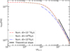 |
Fig. 7 Evolution of the synchrotron-self absorption frequency vssa with time for the same case shown in Fig. 5. Different types of lines show vssa as derived from the numerical solutions for different choices of the time step (see inset legend). For comparison, we show the analytical prediction for the late-time (t ≫ R0 /Vexp) evolution of vssa with time. |
Parameter values for scenarios used to test the accuracy and performance of LeHaMoC.
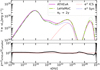 |
Fig. 8 Comparison of the steady-state photon spectra of ATHEvA code and LeHaMoC for a leptohadronic scenario for blazar emission. All displayed spectra are measured in the comoving frame of the spherical blob. The colored dashed lines are used to indicate the contribution to the photon spectrum coming from the pairs (blue and red) and the decay of neutral pions (green) to γ-rays before attenuation. The parameters used for this test can be found in Table 2 under column Test 4. |
4 Astrophysical applications
To demonstrate the fitting capabilities of the newly developed code we first model a blazar SED using emcee (Foreman-Mackey et al. 2013), a python implementation of the Affine invariant Markov chain Monte Carlo (MCMC) ensemble sampler. This allows us to better estimate the uncertainties in model parameters and to explore possible degeneracies in this multi-parameter problem. To illustrate the capabilities in computing hadronic-initiated electromagnetic cascade spectra, we present a pp-interaction model for the neutrino signal from the nearby Seyfert galaxy NGC 1068.
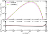 |
Fig. 9 Comparison of the steady-state all-flavor neutrino spectra computed with ATHEvA and LeHaMoC codes for Test 4. |
4.1 Blazar SED fitting
For this application, we choose 3HSP J095507.9+355101 (Giommi et al. 2020; Paliya et al. 2020), which is a BL Lac object at redshift z = 0.557 (Paiano et al. 2020; Paliya et al. 2020) that belongs to the rare class of extreme blazars3 (Biteau et al. 2020). This blazar has been detected in GeV γ-rays by the Fermi Large Area Telescope (LAT) and is part of the 4FGL catalog (Abdollahi et al. 2020). It has also been possibly associated with a high-energy neutrino IceCube-200107A detected by the IceCube Neutrino Observatory (IceCube Collaboration 2020) one day before the blazar was found to undergo a hard X-ray flare.
Various emission models of the 3-day X-ray flare, including one-zone leptohadronic scenarios, were presented in Petropoulou et al. (2020). In all cases, the parameter values were selected based on physical arguments instead of being derived from a fitting procedure. The long execution time of the radiative code ATHEvA, even for a pure leptonic emission model, deemed necessary this “eyeball” description of the SED (see also Petropoulou et al. 2015, 2017). Here, we demonstrate that SED fitting using the newly developed code and a Bayesian inference approach is feasible with limited computational resources. 3HSP J095507.9+355101 is ideal for this application. First, our results can be compared to SED models that are available in the literature. Second, we can investigate how the different spectral coverage of the low- and high-energy SED humps (see below for more details) affects our results.
We use the multi-wavelength data of January 11, 2020 (4 days after the neutrino detection) when the source was observed for the first time in hard X-rays by NuSTAR (Harrison et al. 2013). The quasi-simultaneous observations in the UV, soft X-rays, and hard X-rays provide a detailed picture of the low-energy part of the spectrum (see black symbols in Fig. 10). On the contrary, the high-energy part of the spectrum is less constrained observationally. Given that 3HSP J095507.9+355101 is a faint γ-ray source, the Fermi data need to be averaged over a long period (250 days) to allow for a significant detection of the source at least in two energy bins (see magenta symbols in Fig. 10). For details about the data selection and analysis, we refer the reader to Giommi et al. (2020).
The statistical uncertainties of the flux measurements typically underestimate uncertainties that stem from the non-simultaneity of data used in the SED, since blazar emission is variable on timescales of days to months (e.g. the X-ray data are obtained from ~ks observations, while the γ-ray data are averaged over 250 days). We, therefore, add a term ln f to the likelihood function to account for any source of uncertainty that is not included in the statistical uncertainties of the measurements (for a similar application, see Karaferias et al. 2023),
 (12)
(12)
Here, fm,i stands for the model flux (in logarithm) evaluated at the frequency of the i-th data point, fi is the measured flux, and σtot,i is the total variance, which is defined as
 (13)
(13)
with σi being the errors of the flux measurements. We also note that the upper limits are included in fit by adding the following term in the likelihood function (see Sawicki 2012; Yang et al. 2020):
![Mathematical equation: $\sum\limits_j {\ln } \left( {\sqrt {{\pi \over 2}} {\sigma _j}\left[ {1 + {\mathop{\rm erf}\nolimits} \left( {{{{f_{{\rm{lim }},{\rm{j}}}} - {f_{m,j}}} \over {\sqrt 2 {\sigma _j}}}} \right)} \right]} \right),$](/articles/aa/full_html/2024/03/aa47277-23/aa47277-23-eq26.png) (14)
(14)
where flim,j is the jth flux upper limit (in logarithm) and σj is the respective uncertainty.
We apply first an SSC model with synchrotron self-absorption and intrinsic γγ pair production included. The electron distribution is modeled as a power law of slope se that starts from γe,min and extends to a sharp high-energy cutoff at γe,max. In the MCMC fitting all parameters are sampled from uniform distributions in logarithmic space, except for the power-law slope of the particle distribution, which is sampled from a uniform distribution in linear space. We produce a chain with 48 walkers that are propagated 50 000 steps each and discard the first 5 000 steps of each chain as burn-in. The corner plot showing the posterior distributions of the parameters is presented in Fig. C.1, and a random selection of SSC spectra computed using 100 posterior values is shown in Fig. 10. For comparison purposes, we include an SSC spectrum used in Petropoulou et al. (2020) as an “eyeball” description of the SED (model D). The displayed SSC spectra highlight the importance of obtaining flux measurements with small uncertainties. In particular, the UV and X-ray measurements act as nodes for the model and help decrease the spread in the predicted synchrotron component of the SED. On the contrary, the high-energy hump of the SED is less constrained (due to upper limits and large error bars in the LAT energy range), leading to a larger spread in SSC spectra (and physical conditions) that are statistically compatible with the observations. While model D of Petropoulou et al. (2020) falls within the range of SSC spectra found by the Bayesian inference, it is only one of the possible realizations of the emitting region (see also corner plot in Fig. C.1).
We next consider the simplest lepto-hadronic scenario where relativistic protons are injected into the source with a power-law distribution and produce photons only via synchrotron radiation. This is known as the proton-synchrotron (PS) model for γ-ray blazar emission (Aharonian 2000; Mücke & Protheroe 2001). For this illustrative example, we neglect photo-hadronic interactions but note that these may not be negligible for all the parameters explored by the walkers in the chain. We defer a full lepto-hadronic MCMC modeling for future work. Figure 11 shows 100 SEDs (solid orange lines) obtained by randomly selecting 100 parameter sets from the posterior distributions shown in Fig. C.2. The proton-synchrotron model discussed in Petropoulou et al. (2020) is also plotted for comparison purposes (dashed blue line). Without imposing any constraints on the parameters (e.g. same power-law slopes or maximum energies for the electron and proton distributions), the low- and high-energy humps of the SED are decoupled. This, in combination with the γ-ray upper limits, leads to solutions with a spread in the predicted γ-ray peak energy. This spread in solutions is also reflected in the broad posterior distributions of the parameters describing the proton distribution. For example, the minimum proton energy and power-law slope cannot be constrained, thus justifying the simplifying assumption of fixing these parameters to default values (see Petropoulou et al. 2020).
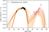 |
Fig. 10 SED of 3HSP J095507.9+355101 using data from Giommi et al. (2020). Black symbols indicate observations taken on January 11, 2020 (i.e. soon after the arrival of the neutrino alert). Magenta symbols show the time-integrated Fermi-LAT data over a period of 250 days prior to the neutrino alert. SSC spectra computed for a random sample of 100 points from the posterior distributions are overplotted (solid orange lines). For comparison, the SSC model from Petropoulou et al. (2020) is also shown (dashed blue line). Photon attenuation by the extragalactic background light (EBL) is not taken into account. |
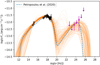 |
Fig. 11 Same as in Fig. 10 but for a proton synchrotron (PS) model of the SED. For comparison, the PS model from Petropoulou et al. (2020) is also shown (dashed blue line). |
4.2 Electromagnetic cascades in high-energy neutrino sources
NGC 1068 is a prototypical Seyfert 2 galaxy at dL ≃ 14.4 Mpc4 (Meyer et al. 2004) exhibiting AGN and starburst activity in its central region (Neff et al. 1994). Due to its proximity, it is the best-studied galaxy of this type. The estimated mass of the supermassive black hole (SMBH) in NGC 1068 is approximately 20 million times the mass of the Sun, i.e. M ≃ 107.3M⊙ (Panessa et al. 2006), and the corresponding Schwarzschild radius is Rs ≃ 6 × 1012 cm. It is a well-known bright X-ray source with estimated intrinsic X-ray luminosity (in the 0.1–200 keV range) of ~4.6 × 1043 erg s−1 (Bauer et al. 2015). NGC 1068 is also detected in GeV γ-rays by Fermi-LAT (Lenain et al. 2010; Abdollahi et al. 2020), but upper limits are set at even higher energy by MAGIC (Acciari et al. 2019). Recently, the IceCube Collaboration has reported a high-energy neutrino excess (at 4.2 σ confidence level) associated with NGC 1068 (IceCube Collaboration 2022), strengthening previous reports of a 2.9σ excess in the 10-year time-integrated search (Aartsen et al. 2020).
Many models for the neutrino and/or γ-ray emission of NGC 068 can be found in the literature (e.g. Murase et al. 2020; Kheirandish et al. 2021; Inoue et al. 2022; Eichmann et al. 2022). We do not attempt to offer a new interpretation but rather present the capabilities of our code using one of the published one-zone models for NGC 1068. In particular, we adopt the AGN corona scenario of Murase (2022) in which neutrinos are produced via pp interactions in a magnetized corona and γ-rays are attenuated via the disk-corona radiation field. For simplicity, we ignore the emission from accelerated (primary) electrons in the corona and focus on the electromagnetic cascade developed by secondary pairs. While details of the model can be found in Murase (2022), we outline below the basic model ingredients for completeness.
We assume that protons are accelerated in the corona into a power-law distribution, i.e.  , where Ep = mpγpc2. Relativistic protons can interact with the cold (i.e. non-relativistic) protons present in the corona. The number density of the latter is approximated as
  , where τT represents the coronal optical depth to Thomson scattering, ζe is the pair loading factor (i.e. number of pairs per proton), and R is the characteristic size of the corona. Introducing the normalized radius 𝓡 = R/Rs, the coronal cold proton density is estimated as np,c ≃ 109 cm−3
  , where we used the notation qx = q/10x.
Given that the produced neutrino has a typical energy Ev ~ Ep/20, we require Ep,min ~ 20 TeV to reproduce the low-energy end of the neutrino spectrum observed by IceCube. Because the spectrum of secondary particles produced in pp collisions follows closely the proton spectrum (Kelner et al. 2006), we adopt the same slope for the parent proton distribution as the best-fit value for the spectral index of the neutrino spectrum determined by IceCube (i.e., sp = sv = 3.2). We assume that the luminosity of the accelerated protons is comparable to the intrinsic X-ray luminosity of the corona, namely Lp =1043.8 erg s−1.
Following (Murase 2022) we introduce the parameter ξB, which is defined as the ratio of magnetic field energy density, UB = B2/(8π), to the bolometric energy density of photons, Uph = Lbol/(4πR2c). Here, B represents the magnetic field strength, and the photon field is assumed to be distributed within a spherical source of radius R. Given these considerations, the magnetic field strength can be expressed as B ≈ 1.4 × 10³ G  . Photons from neutral pion decay may pair produce on the disk-corona photon field. For our example, we adopt the spectral template for Lbol = 1045 erg s−1 from Murase et al. (2020, see Fig. 2 therein). Pairs produced via γγ pair production and charged pion decays emit synchrotron radiation and inverse Compton scatter photons to high-energy, thus leading to the development of an electromagnetic cascade in the coronal region. Finally, all charged particles are assumed to escape from the corona on a timescale tesc = 100R/c, while photons and neutrinos escape on R/c.
In Fig. 12, we present the broadband SED of our model for the case of an extended corona with radius R = 100 RS and ξB = 1. Neutral pions decay into γ-ray photons with a spectrum similar to the neutrino spectrum (solid magenta line). These energetic photons are attenuated by low-energy photons present (e.g. attenuation due to the disk thermal emission is evident by the dip at energies E/(mec2) ≈ 106), leading to the production of secondary pairs that emit synchrotron radiation (solid blue line) and inverse Compton scatter photons from the disk-corona system (solid green line). For reference, we also plot the differential proton luminosity that is injected in the corona (dashed black line).
The high-energy photon and neutrino spectra of the model are compared to multi-messenger data of NGC 1068 in Fig. 13 for ξB = 1 and different values of the source radius, to illustrate the effects of γ-ray attenuation. For comparison, we also show the photon spectrum without accounting for γγ absorption, represented by the dashed colored lines. Our results reveal that the emission within the 0.1–10 GeV range is primarily generated through synchrotron radiation. In this particular model, the magnetic field strength is inversely proportional to the radius of the source. As a result, stronger magnetic fields are expected in more compact regions (with smaller radii), pushing the synchrotron spectrum of secondaries to higher energies. As anticipated, we observe a greater degree of γγ absorption in more compact regions, but in all cases, the expected TeV emission from neutral pion decays is attenuated, hence all models are consistent with the MAGIC upper limits. We note that we have not included other potential sources of attenuation, such as the thermal emission from the dust torus. The model neutrino spectrum falls within the IceCube uncertainty band (95% confidence level) as expected. It is worth noting that the computed neutrino spectrum exhibits a spectral break at 0.1 TeV. This feature arises from the adoption of the δ-function approximation for pion production at energies below this limit, as described in Kelner et al. (2006) – see also Appendix A. Because of this assumption, the neutrino spectrum below 0.1 TeV is harder than the one presented in Murase (2022), where the full neutrino spectrum produced by the minimum energy pions in the system was computed.
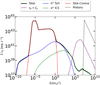 |
Fig. 12 Spectral energy distribution of NGC 1068 is analyzed by considering an emitting region with R = 100 Rs. The total photon spectrum originating from this region is shown by the solid black line. The solid red line represents the combined contribution of the corona and disk components (template adopted from Murase et al. 2020). Solid blue and green lines represent the synchrotron and ICS emission produced by the secondary particles, respectively. The neutrino spectrum is depicted by the purple line, and the black dashed line represents the injected luminosity of protons. |
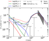 |
Fig. 13 γ-ray and neutrino emission of NGC 1068. Black symbols and grey arrows indicate γ-ray measurements by Fermi-LAT (Abdollahi et al. 2020) and upper limits by MAGIC (Acciari et al. 2019), respectively. Colored solid (dashed) lines represent the γ-ray spectrum produced by the electromagnetic cascade inside the corona with (without) γγ absorption respectively, for different choices of radius and magnetic field (see legend and text for details). The solid dark line represents the muon and anti-muon neutrino spectrum, and the grey-shaded region covers all power-law neutrino fluxes that are consistent with the IceCube data at 95% confidence level (IceCube Collaboration 2022). |
5 Conclusions
In this work, we have presented our newly developed code, LeHaMoC, which aims to describe the multi-messenger emission of non-thermal astrophysical sources. LeHaMoC solves the kinetic equations using an implicit scheme assuming that the particles occupy a spherical region and they are homogeneous. The highlights of our work include the comprehensive treatment of various non-thermal processes, the efficient computational times achieved for different scenarios, the inclusion of energy-conserving schemes, and the adiabatic expansion of the source.
These features make LeHaMoC a valuable tool for studying non-thermal sources and their associated emission mechanisms.
One of the notable achievements of LeHaMoC is the significant reduction in computation times compared to the ATHEvA code. We have demonstrated that LeHaMoC can solve steady-state problems, involving leptons inside the emission region, in approximately ~2–3 seconds which is a factor of 30100 shorter than ATHEvA. For proton-proton steady-state scenarios, LeHaMoC achieves computation times on the order of ~20 seconds, and for photohadronic steady-state scenarios, it takes approximately ~10 min (factor of 3 faster than ATHEvA). The improvement in the execution time can be attributed to the following factors. In comparison with LeHaMoC, the time discretization in ATHEvA is not user-configurable, instead, it is predefined within the algorithm5. It is established based on the most significant derivative encountered, considering all processes and grid points. As a result, if the initial conditions result in substantial derivatives, the time step becomes quite small, often extending the computation time required to reach a steady state. Typically, this results in computations taking a considerable amount of time, sometimes spanning the first few light-crossing times. On the contrary, the steady-state solutions are not sensitive to the choice of time step within the Chang & Cooper scheme employed in LeHaMoC; hence, larger time steps can be employed leading to faster computations for steady-state problems. Besides the different numerical schemes, there are discrepancies in the way certain processes are incorporated within each code. A more detailed explanation of the process implementation in LeHaMoC can be found in Appendix A. Notable distinctions are the injection rates of the Bethe-Heitler and the pho-topion processes. In the ATHEvA code the Bethe-Heitler pair production rates and photopion production rates are based on tabulated Monte-Carlo results from Protheroe & Johnson (1996) and Mücke et al. (2000), respectively (for the implementation in ATHEvA see Mastichiadis et al. 2005; Dimitrakoudis et al. 2012). In LeHaMoC we use instead the analytical parametriza-tions of Kelner & Aharonian (2008) for the energy distributions of secondary particles produced from photopion interactions and simplify the calculation of pair distribution from Bethe-Heitler production as described in Appendix A. The improved efficiency of LeHaMoC allows for more extensive simulations and understanding of the high-energy astrophysical sources.
The small computational time of LeHaMoC enables the application of advanced data fitting techniques, such as Markov chain Monte Carlo (MCMC) methods. Using emcee we have demonstrated the capability of LeHaMoC to fit the SED of a blazar, using two different scenarios and taking into account the observations in the X-rays and γ-rays. By employing MCMC techniques, we gain a deeper understanding of the underlying physical parameters and their associated uncertainties, enabling us to effectively reproduce the observed spectrum. Furthermore, our analysis revealed that the spread in fluxes across the electromagnetic spectrum can be larger than the systematic differences of 10% between radiative transfer codes, including the ATHEvA code. Additionally, our results emphasize the importance of dense sampling of the SED through multiwave-length observing campaigns to capture the full complexity of non-thermal sources.
Other significant aspects of the code are the inclusion of energy-conserving treatment between the particles and the photons and the consideration of photons that are produced from the secondary particles as targets for particle-photon interactions. This latter feature allows the study of optically thick environments where feedback effects are important for driving oscillatory (limit-cycle) behavior found in hadronic supercriti-calities (Petropoulou & Mastichiadis 2012; Mastichiadis et al. 2005, 2020). By accurately accounting for these interactions, LeHaMoC may provide a more comprehensive description of the photon spectra escaping such environments.
Despite the advancements achieved in LeHaMoC there are still challenges to be addressed. The computational time needed for photohadronic scenarios currently prohibits the MCMC fitting applied to high-energy astrophysical sources. Furthermore, small changes in the physical parameters may lead to different spectral characteristics due to the interplay of the physical processes. To overcome these challenges, one potential way to move forward is to explore the use of neural networks as an alternative to numerical codes. Neural networks have gained traction in various fields, such as astrophysics (Hezaveh et al. 2017), space weather forecasting (Camporeale 2019), and biology (Wang et al. 2019). Implementing neural networks in the analysis of high-energy astrophysical emission could provide a more efficient approach to fitting big data sets by reducing significantly the computation time while providing an accuracy comparable to the uncertainties of emission models.
Acknowledgements
We thank the anonymous referee for his/her useful feedback. We thank Kohta Murase for insightful discussions about NGC 1068. We also thank Stella Boula and Paolo Padovani for useful comments on the manuscript. S.I.S. and M.P. acknowledge support from the Hellenic Foundation for Research and Innovation (H.F.R.I.) under the “2nd call for H.F.R.I. Research Projects to support Faculty members and Researchers” through the project UNTRAPHOB (Project ID 3013). G.V. acknowledges support by H.F.R.I. through the project ASTRAPE (Project ID 7802).
Appendix A Radiative processes
Adiabatic losses
Particles inside an expanding spherical region of radius R will undergo energy losses as they do work. The energy losses of particle species i are related to the expansion rate and are proportional to the energy of the particle and are given by (Longair 2011):
 (A.1)
(A.1)
where ∈i = γi is the particle Lorentz factor of particle species i with rest mass energy mic2 (or frequency v for photons and neutrinos). Therefore, the loss term that appears in Eqs. 1, 2 and 3 can be expressed as follows
 (A.2)
(A.2)
Synchrotron emission
The synchrotron emissivity of a relativistic particle species i with rest mass mi, charge e, and differential number density ni(γi) = Ni(γi)/V (where V is the volume of the emitting region) is given by (Boettcher et al. 2012):
 (A.3)
(A.3)
where mi is the mass of the charged particle, Γ(x) is the Gamma function, UB = B2/8π is the magnetic energy density, and vc is the critical synchrotron frequency
 (A.4)
(A.4)
Given the above, we can now define the synchrotron source and loss terms that appear in Eqs. 1, 2, and 3 as
 (A.5)
(A.5)
 (A.6)
(A.6)
where dγi/dt are the energy losses of the particle species i due to synchrotron radiation
 (A.7)
(A.7)
Synchrotron self-absorption
Low-energy charged particles in the plasma can re-absorb some of the emitted synchrotron radiation. This process is known as synchrotron self-absorption. The synchrotron self-absorption coefficient (often denoted as αssα(v)) is a measure of how much of the radiation produced by a synchrotron source is absorbed by the emitting plasma itself, rather than being observed by an external observer. The coefficient for a charged particle with mass mi is given by (Dermer & Menon 2009):
![Mathematical equation: ${a_{v,ssa}} = - {1 \over {8\pi {m_i}{v^2}}}\int_1^\infty d \log {\gamma _i}\left[ {{{d{n_i}\left( {{\gamma _i}} \right)} \over {d\log {\gamma _i}}} - 2{n_i}\left( {{\gamma _i}} \right)} \right]{P_i}\left( {v,{\gamma _i}} \right),$](/articles/aa/full_html/2024/03/aa47277-23/aa47277-23-eq38.png) (A.8)
(A.8)
where Pi· is the synchrotron power spectrum emitted by a single particle (see Eq. 2.15 and Eq. 2.18 in Ghisellini & Svensson 1991) assuming only head-on collisions. We can then define the optical depth as follows
 (A.9)
(A.9)
The photon spectrum is strongly absorbed below a frequency at which the optical depth is above unity (τv,ssa ≥ 1). We then introduce the synchrotron self-absorption loss term in Eq. 3 as follows
 (A.10)
Inverse Compton scattering
Charged particles can also up-scatter photons via Inverse Comp-ton (IC) scattering. In this work, we consider only IC scattering by electrons (and positrons), since proton IC scattering is negligible for most astrophysical sources (Kelner & Aharonian 2008) (see, however, Gao et al. 2017).
In the general case, where we use the exact Klein-Nishina formula for the cross-section, the scattered photon spectrum per electron can be expressed using the frequency of the scattered photon in units of the initial electron energy (v1 = γemec2 Assuming that the photons undergo IC scattering by an electron population with differential number density ne(γe), then the emissivity of IC scattering is given by (Blumenthal & Gould 1970):
![Mathematical equation: $\matrix{ \hfill {{j_{{v_1}}} \equiv {{dN} \over {dtd{v_1}dV}} = {\sigma _T}c\int_1^\infty {{n_e}} \left( {{\gamma _e}} \right)\int_0^\infty {{{{n_\gamma }(v)} \over {4\gamma _e^2v}}} [2q\ln (q) + } \cr \hfill {\left. {(1 + 2q)(1 - q) + {1 \over 2}{{{{\left( {{\Gamma _}q} \right)}^2}} \over {1 + {\Gamma _}q}}(1 - q)} \right]dvd{\gamma _e},} \cr } $](/articles/aa/full_html/2024/03/aa47277-23/aa47277-23-eq41.png) (A.11)
(A.11)
where ne(γe) = dNe/dVdγe, nγ(v) = dNγ/dVdv, Γ∈ = 4hvγe/mec2, and q = E1/Γ∈(1 − E1).
We, therefore, introduce the inverse Compton scattering source term in Eq. 3 as follows
 (A.12)
We account only for energy losses that are occurring in the Thomson regime. The Lorentz factor of electrons undergoing IC scattering in this regime can be expressed as follows
 (A.13)
where Uph(γe) is given by (Mastichiadis & Kirk 1995):
 (A.14)
Therefore, the loss term that appears in Eq. 1 can be written as follows
 (A.15)
Photon-photon pair production
A process that acts as a sink of high-energy photons, and as a source term for relativistic electrons is photon-photon pair creation. We introduce the absorption coefficient for a given high energy photon with frequency v1 as follows
 (A.16)
where σγγ is the cross-section of the process, y = ∈∈1 with ∈ and ∈1 being the target and the γ-ray photon energies respectively normalized to the electron’s rest mass energy. We use an approximation for the cross section from (Coppi & Blandford 1990):
 (A.17)
where Θ(y) is the Heavyside function. We, therefore, introduce the γγ absorption loss term in Eq. 3 that reads
 (A.18)
The volumetric production rate of relativistic electrons (or positrons) of Lorentz factor γe is given by (Mastichiadis & Kirk 1995):
 (A.19)
where Rγγ is an approximation to reaction rate of the process (Mastichiadis & Kirk 1995). In the previous equation, all angle effects are neglected and we have assumed that the emerging pair has energy equal to that of the absorbed γ-ray. This leads to the following source term in Eq. 1
 (A.20)
Bethe-Heitler pair production
Bethe-Heitler pair production refers to the process of creating an electron-positron pair by a relativistic proton interacting with a low-energy photon. For ultra-relativistic protons γp ≫ 1, the pair spectrum is given by (Kelner & Aharonian 2008):
 (A.21)
where W(ω, E−, ξ) is the cross-section (Blumenthal 1970) and all energies above are normalized to the electron rest mass energy. The last integral in Eq. A.21, involving the cross-section, can be computationally challenging and can increase the computation time of a simulation significantly. To overcome this problem, we calculate the integral for various combinations of γe, γp, and ω, from a large sample, given the parameters of each simulation, and store them in an array. In Fig. A.1, we illustrate the third integral from Eq. A.21 for several values of  and E−,mαx = ω − 1. The upper panel of Fig. A.1 depicts the integral’s value when γp > γe, whereas the lower panel represents the scenario with the reverse condition. Notably, we observe a division of the integral into two distinct regions at the plane where γp = γe. By using interpolation, the desired integral values can be obtained efficiently, thus reducing the computational time by a factor of ~20 − 30.
In order to calculate the volumetric production rate of pairs coming from a proton distribution np(γp) = Np(γp)/V we use
 (A.22)
Therefore for the source term of relativistic electrons in Eq. 1 we use
 (A.23)
The energy loss rate of a high energy proton with Lorentz factor γp is given by (Blumenthal 1970):
 (A.24)
where αf is the fine structure constant and the function ϕ(ξ) is adopted from Fig. 2 of (Blumenthal 1970). The energy loss term in Eq. 2 can be then written as
 (A.25)
Photomeson production process
Photomeson interactions refer to the process by which low-energy photons interact with high-energy protons, resulting in the production of mainly π0 and π± mesons. The produced pions will decay in γ-rays and leptons. The production rate of a given type of particle with energy El, where l can be  , from a proton distribution np(Ep) = Np(Ep)/V is given by (Kelner & Aharonian 2008):
 (A.26)
where Ep = γpmpc2, e is the photon energy normalized to mec2, x is the ratio between the energy of the produced particle and the proton’s energy and Φl(η, x) is the energy distribution of the species l – see Eq. (31) and Tables I-III in Kelner & Aharonian (2008).
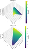 |
Fig. A.1 Third integral of Eq. A.19 for several values of the integration limits here denoted as E−,min and E−,max. The top panel shows the integral’s value for γp > γe, while the bottom panel shows the integral’s values for γp <γe. |
Therefore for the source term of relativistic particles with energy El in Equations 1, 3, and 4 we use
 (A.27)
The energy loss rate of a high energy proton with Lorentz factor γp are given by (Begelman et al. 1990):
 (A.28)
where  denotes the density of photons in the emission region’s frame of reference while all bared quantities are measured in the proton’s rest frame. The energy-dependent cross-section and the inelasticity of the process are represented as σpπ and kp and are adopted from (Morejon et al. 2019) and (Stecker 1968) respectively.
The energy loss term in Eq. 2 can then be written as
 (A.29)
Proton-proton (pp) inelastic collisions
High-energy protons may interact with non-relativistic (cold) protons in dense astrophysical environments. Inelastic proton-proton collisions lead to the production of secondary particles, γ-rays, pairs, and neutrinos. The production rate of a given type of particle with energy El, where l can be y,  , from a proton distribution np(Ep) = Np(Ep)/V is given by (Kelner et al. 2006):
 (A.30)
where Ep = ypmpc2, x = El/Ep, ng is the number density of cold protons in the ambient gas, and σpp,¡nel is the cross-section of inelastic pp interactions. The function Fl(x, El/x) is related to the energy distribution of particle species l. We use the empirical functions as described in (Kelner et al. 2006) for Ep > 0.1 TeV, and xl = El/Ep ≥ 10–3, while for values Ep < 0.1 TeV the spectra of γ-ray photons and other secondaries are computed to lower energies using the δ-function approximation for pion production as described in the same manuscript.
Therefore, the source term of relativistic particles with energy El in Eqs. 1, 3 and 4 is given by,
 (A.31)
The energy loss rate of a high energy proton with Lorentz factor γp ≫ 1 is given by (see Eq. 4.11 in Mannheim & Schlickeiser 1994):
 (A.32)
where Ep,th = γp,thmpc2 and γp,th= 1 + (mπ/mp)(1/2+ mπ/(2mp)).
The energy loss term in Eq. 2 can be written as
 (A.33)
Appendix B Kinetic Equations: number density versus particle number
In this section, we examine the results obtained by numerically solving the kinetic equation when this is expressed with respect to the particle number density or to the particle number. As the first example, we demonstrate the numerical solution of Test 3 using the number density in the kinetic equation instead of the number of particles. We can discretize Eq. 1 into time ti and Lorentz factor γj for the two cases. When the kinetic equation is written in terms of the particle number, the discretization reads
 (B.1)
(B.1)
where the coefficients are
 (B.2)
(B.2)
 (B.3)
(B.3)
 (B.4)
(B.4)
On the other hand, when we discretize the equation written in terms of the number density, we find
 (B.5)
(B.5)
where the coefficients are
 (B.6)
(B.6)
 (B.7)
(B.7)
 (B.8)
(B.8)
In Figure B.1, we depict the numerical solution obtained after solving Eq. (B.5) with two choices of the time step (represented by dotted and dashed-dotted lines). The only disparity between the coefficients in Eqs. (B.1) and (B.5) lies in the coefficient V2,j. When solving the kinetic equation utilizing the number density, an extra term emerges from the time derivative of the volume, specifically  . We observe that the numerical solution diverges by almost an order of magnitude in normalization from the analytical one when a large time step is chosen – the difference is smaller when the kinetic equation with respect to the number is solved (compare to Fig. 5). To ensure a better agreement with the analytical solution, the time step has to satisfy
  .
.
As a second example, we consider an expanding spherical source containing particles that undergo only adiabatic losses. We assume a constant injection of particles (e.g. electrons) with a power-law distribution of slope se between γmin and γmax. The source is expanding with velocity Vexp = 0.1c. This problem has no steady-state solution and is also ideal for examining the performance of a numerical solver in time-dependent scenarios.
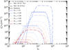 |
Fig. B.1 Comparison between numerical solutions (represented by dashed and dashed-dotted lines) and analytical solutions (represented by solid lines) using the same parameters as Test 3, using the number density in the kinetic equation. The numerical results were obtained with varying time steps, which are indicated in the legend. |
The analytical solution to the kinetic equation is given by the following expression
![Mathematical equation: ${N_e}(\gamma ,t) = K{{1 + {\beta _0}t} \over {{\beta _0}{s_e}}}\left[ {1 - {{\left( {1 + {\beta _0}t} \right)}^{ - {s_e}}}} \right]{\gamma ^{ - {s_e}}},{\gamma _{\min }} \le \gamma \le {\gamma _{\max }},$](/articles/aa/full_html/2024/03/aa47277-23/aa47277-23-eq78.png) (B.9)
(B.9)
where β0 = Vexp/R0 and K is a normalization constant.
The discretize Eq. 1 into time ti and Lorentz factor γj in terms of the particle number
 (B.10)
where the coefficients are given by Eqs. B.2, B.3 and B.4
On the other hand, when we discretize the equation written in terms of the number density, we find
 (B.11)
where the coefficients are given by Eqs. B.6, B.7 and B.8
Again the only difference between the coefficients in the equations above lies in the coefficient V2,j. When solving the kinetic equation using the number density, an additional term arises from the time derivative of the volume  . In figures B.2 and B.3, we display both the numerical and analytical solutions for the two cases, considering two different time steps for each scenario. Our findings reveal that when using the particle number approach, the numerical and analytical solutions exhibit the same behavior for both choices of Δt. However, when solving the kinetic equation using the number density of particles, we observe a discrepancy between the analytical and numerical solutions for larger time steps. It is important to note that this discrepancy arises when the chosen time step Δt > R0/(3Vexp). Consequently, we choose to solve the kinetic equation using the particle number rather than the number density, as it yields more accurate numerical solutions without the need for very small time steps.
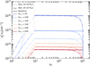 |
Fig. B.2 Comparison of numerical (dashed and dotted lines) resulted by solving Eq. B.1 and analytical (solid lines) solutions for adiabatic cooling electrons in an expanding blob with constant injection. Numerical solutions for two choices of the time step are shown as indicated in the legend. The evolution of the particle distribution in time is indicated by the different colors. |
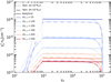 |
Fig. B.3 Comparison of numerical (dashed and dotted lines) resulted by solving eq. B.5 and analytical (solid lines) solutions for adiabatic cooling electrons in an expanding blob with constant injection. Each numerical result was calculated using a different time step as indicated in the legend. |
Appendix C Corner plots
We present corner plots showing the posterior distributions of parameters for an SSC and a proton-synchrotron model for blazar 3HSP J095507.9+355101. Inspection of the corner plot in Fig. C.1 shows that most parameters of the SSC model are well-constrained. However, the radius of the source cannot be pinned down by the SED fitting, suggesting that more information is needed. For example, knowledge of the variability timescale could help eliminate further the posterior distribution. To better understand why the posterior distribution of the radius is not very peaked, let us consider the following. Assuming that electrons are radiating away via synchrotron radiation their injected luminosity, then the synchrotron luminosity in the observer’s frame would scale as  . Given that the 68 % of values for δ and ℓe span a range of about 100.6 and 10 respectively, the radius should range within a factor of ~103.4 for a fixed observed luminosity. This range is roughly equal to the one used in the prior distribution of R, thus explaining the broad range of radii that yield acceptable fits to the data. Regarding the minimum electron Lorentz factor, its posterior distribution is bimodal, with most solutions favoring higher values. Stronger constraints on this parameter could be placed if observations at GHz frequencies and soft γ-rays (1021 – 1022 Hz) would be available, as these ranges probe the lower energy radiating electrons. When a model with more parameters is applied to the same data, larger uncertainty in the derived parameter values is expected. This is demonstrated in the corner plot for the PS model (Fig. C.2), where one can see that the posterior distributions for the parameters describing the proton distribution (e.g. γp,min, γp,min, sp) are very similar to their priors. Some solutions could be excluded a posteriori by implying physical constraints (e.g. by requiring the gyroradius of the maximum energy protons to be smaller than the source size). Nevertheless, it becomes clear that in physical models where the low- and high-energy components of the SED are produced by different particle populations, the parameter space that yields acceptable fits to the data is large.
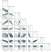 |
Fig. C.1 Corner plot showing the posterior distributions of the parameters of the SSC model of 3HSP J095507.9+355101. Dashed lines in the histograms indicate the median value of each parameter and the 68 % range of values. The parameter values used in model D from Petropoulou et al. (2020) are overplotted (magenta square) for comparison. |
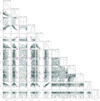 |
Fig. C.2 Corner plot showing the posterior distributions of the parameters of the PS model of 3HSP J095507.9+355101. Dashed lines in the histograms indicate the median value of each parameter and the 68 % range of values. The parameter values used in the PS from Petropoulou et al. (2020) are overplotted (magenta square) for comparison. |
References
- Aartsen, M. G., Ackermann, M., Adams, J., et al. 2020, Phys. Rev. Lett., 124, 051103 [Google Scholar]
- Abdollahi, S., Acero, F., Ackermann, M., et al. 2020, ApJS, 247, 33 [Google Scholar]
- Acciari, V. A., Ansoldi, S., Antonelli, L. A., et al. 2019, ApJ, 883, 135 [NASA ADS] [CrossRef] [Google Scholar]
- Aharonian, F. A. 2000, New Astron., 5, 377 [NASA ADS] [CrossRef] [Google Scholar]
- Bauer, F. E., Arévalo, P., Walton, D. J., et al. 2015, ApJ, 812, 116 [Google Scholar]
- Begelman, M. C., Rudak, B., & Sikora, M. 1990, ApJ, 362, 38 [Google Scholar]
- Biteau, J., Prandini, E., Costamante, L., et al. 2020, Nat. Astron., 4, 124 [Google Scholar]
- Blumenthal, G. R. 1970, Phys. Rev. D, 1, 1596 [NASA ADS] [CrossRef] [Google Scholar]
- Blumenthal, G. R., & Gould, R. J. 1970, Rev. Mod. Phys., 42, 237 [Google Scholar]
- Boettcher, M., Harris, D. E., & Krawczynski, H., eds. 2012, Relativistic Jets from Active Galactic Nuclei (Wiley) [CrossRef] [Google Scholar]
- Böttcher, M., Reimer, A., Sweeney, K., & Prakash, A. 2013, ApJ, 768, 54 [Google Scholar]
- Boula, S., & Mastichiadis, A. 2022, A&A, 657, A20 [NASA ADS] [CrossRef] [EDP Sciences] [Google Scholar]
- Camporeale, E. 2019, Space Weather, 17, 1166 [CrossRef] [Google Scholar]
- Cerruti, M., Zech, A., Boisson, C., & Inoue, S. 2015, MNRAS, 448, 910 [Google Scholar]
- Cerruti, M., Kreter, M., Petropoulou, M., et al. 2022, in 37th International Cosmic Ray Conference, 979 [Google Scholar]
- Chang, T., & Cooper, G. 1970, J. Comput. Phys., 6, 1 [CrossRef] [Google Scholar]
- Coppi, P. S., & Blandford, R. D. 1990, MNRAS, 245, 453 [NASA ADS] [Google Scholar]
- Dermer, C. D., & Menon, G. 2009, High Energy Radiation from Black Holes (Princeton, NJ: Princeton University Press) [CrossRef] [Google Scholar]
- Dermer, C. D., & Giebels, B. 2016, Comptes Rendus Physique, 17, 594 [NASA ADS] [CrossRef] [Google Scholar]
- Dimitrakoudis, S., Mastichiadis, A., Protheroe, R. J., & Reimer, A. 2012, A&A, 546, A120 [NASA ADS] [CrossRef] [EDP Sciences] [Google Scholar]
- Eichmann, B., Oikonomou, F., Salvatore, S., Dettmar, R.-J., & Tjus, J. B. 2022, ApJ, 939, 43 [NASA ADS] [CrossRef] [Google Scholar]
- Foreman-Mackey, D., Hogg, D. W., Lang, D., & Goodman, J. 2013, PASP, 125, 306 [Google Scholar]
- Gao, S., Pohl, M., & Winter, W. 2017, ApJ, 843, 109 [NASA ADS] [CrossRef] [Google Scholar]
- Gasparyan, S., Bégué, D., & Sahakyan, N. 2022, MNRAS, 509, 2102 [Google Scholar]
- Ghisellini, G., & Svensson, R. 1991, MNRAS, 252, 313 [NASA ADS] [CrossRef] [Google Scholar]
- Giommi, P., Padovani, P., Oikonomou, F., et al. 2020, A&A, 640, A4 [Google Scholar]
- Harrison, F. A., Craig, W. W., Christensen, F. E., et al. 2013, ApJ, 770, 103 [Google Scholar]
- Hezaveh, Y. D., Perreault Levasseur, L., & Marshall, P. J. 2017, Nature, 548, 555 [Google Scholar]
- IceCube Collaboration 2013, Science, 342, 1242856 [Google Scholar]
- IceCube Collaboration 2018, Science, 361, 147 [NASA ADS] [CrossRef] [Google Scholar]
- IceCube Collaboration 2020, GRB Coordinates Network, 26655 [Google Scholar]
- IceCube Collaboration, Fermi-LAT, MAGIC, et al. 2018, Science, 361, eaat1378 [NASA ADS] [CrossRef] [Google Scholar]
- IceCube Collaboration, Abbasi, R., Ackermann, M., et al. 2022, Science, 378, 538 [CrossRef] [PubMed] [Google Scholar]
- Inoue, S., & Takahara, F. 1996, ApJ, 463, 555 [Google Scholar]
- Inoue, S., Cerruti, M., Murase, K., & Liu, R.-Y. 2022, PRL, submitted [arXiv:2207.02097] [Google Scholar]
- Karaferias, A. S., Vasilopoulos, G., Petropoulou, M., et al. 2023, MNRAS, 520, 281 [NASA ADS] [CrossRef] [Google Scholar]
- Kardashev, N. S. 1962, Soviet Ast., 6, 317 [Google Scholar]
- Kelner, S. R., & Aharonian, F. A. 2008,Phys. Rev. D, 78, 034013; Erratum: 2010, 82, 099901 [NASA ADS] [CrossRef] [Google Scholar]
- Kelner, S. R., Aharonian, F. A., & Bugayov, V. V. 2006, Phys. Rev. D, 74, 034018 [Google Scholar]
- Kheirandish, A., Murase, K., & Kimura, S. S. 2021, ApJ, 922, 45 [NASA ADS] [CrossRef] [Google Scholar]
- Lenain, J. P., Ricci, C., Türler, M., Dorner, D., & Walter, R. 2010, A&A, 524, A72 [NASA ADS] [CrossRef] [EDP Sciences] [Google Scholar]
- Longair, M. S. 2011, High Energy Astrophysics, (Cambridge University Press) [Google Scholar]
- Madejski, G. G., & Sikora, M. 2016, ARA&A, 54, 725 [NASA ADS] [CrossRef] [Google Scholar]
- Mannheim, K. 1993, A&A, 269, 67 [NASA ADS] [Google Scholar]
- Mannheim, K., & Schlickeiser, R. 1994, A&A, 286, 983 [NASA ADS] [Google Scholar]
- Mastichiadis, A., & Kirk, J. 1995, A&A, 295, 613 [NASA ADS] [Google Scholar]
- Mastichiadis, A., Protheroe, R. J., & Kirk, J. G. 2005, A&A, 433, 765 [NASA ADS] [CrossRef] [EDP Sciences] [Google Scholar]
- Mastichiadis, A., Florou, I., Kefala, E., Boula, S. S., & Petropoulou, M. 2020, MNRAS, 495, 2458 [NASA ADS] [CrossRef] [Google Scholar]
- Meyer, M. J., Zwaan, M. A., Webster, R. L., et al. 2004, MNRAS, 350, 1195 [Google Scholar]
- Morejon, L., Fedynitch, A., Boncioli, D., Biehl, D., & Winter, W. 2019, J. Cosmol. Astropart. Phys., 2019, 007 [CrossRef] [Google Scholar]
- Mücke, A., & Protheroe, R. J. 2001, Astropart. Phys., 15, 121 [Google Scholar]
- Mücke, A., Engel, R., Rachen, J. P., Protheroe, R. J., & Stanev, T. 2000, Comput. Phys. Commun., 124, 290 [Google Scholar]
- Murase, K. 2022, ApJ, 941, L17 [NASA ADS] [CrossRef] [Google Scholar]
- Murase, K., Kimura, S. S., & Mészáros, P. 2020, Phys. Rev. Lett., 125, 011101 [Google Scholar]
- Neff, S. G., Fanelli, M. N., Roberts, L. J., et al. 1994, ApJ, 430, 545 [NASA ADS] [CrossRef] [Google Scholar]
- Paiano, S., Falomo, R., Padovani, P., et al. 2020, MNRAS, 495, L108 [Google Scholar]
- Paliya, V. S., Böttcher, M., Olmo-García, A., et al. 2020, ApJ, 902, 29 [NASA ADS] [CrossRef] [Google Scholar]
- Panessa, F., Bassani, L., Cappi, M., et al. 2006, A&A, 455, 173 [NASA ADS] [CrossRef] [EDP Sciences] [Google Scholar]
- Park, B. T., & Petrosian, V. 1996, ApJS, 103, 255 [Google Scholar]
- Petropoulou, M., & Mastichiadis, A. 2012, MNRAS, 421, 2325 [NASA ADS] [CrossRef] [Google Scholar]
- Petropoulou, M., Dimitrakoudis, S., Padovani, P., Mastichiadis, A., & Resconi, E. 2015, MNRAS, 448, 2412 [Google Scholar]
- Petropoulou, M., Vasilopoulos, G., & Giannios, D. 2017, MNRAS, 464, 2213 [NASA ADS] [CrossRef] [Google Scholar]
- Petropoulou, M., Oikonomou, F., Mastichiadis, A., et al. 2020, ApJ, 899, 113 [NASA ADS] [CrossRef] [Google Scholar]
- Protheroe, R. J., & Johnson, P. A. 1996, Astropart. Phys., 4, 253 [NASA ADS] [CrossRef] [Google Scholar]
- Reimer, A., Böttcher, M., & Postnikov, S. 2005, ApJ, 630, 186 [Google Scholar]
- Sawicki, M. 2012, PASP, 124, 1208 [NASA ADS] [CrossRef] [Google Scholar]
- Stecker, F. W. 1968, Phys. Rev. Lett., 21, 1016 [NASA ADS] [CrossRef] [Google Scholar]
- Thomas, L. H. 1949, Watson Scientific Computing Laboratory Report, DSIR O–L, (Columbia University, New York) [Google Scholar]
- Urry, C. M., & Padovani, P. 1995, PASP, 107, 803 [NASA ADS] [CrossRef] [Google Scholar]
- Wang, S., Fan, K., Luo, N., et al. 2019, Nat. Commun., 10, 4354 [NASA ADS] [CrossRef] [Google Scholar]
- Yang, G., Boquien, M., Buat, V., et al. 2020, MNRAS, 491, 740 [Google Scholar]
Blazars are a subclass of AGN with relativistic jets viewed at a small angle (Urry & Padovani 1995).
We determine the ssa frequency by numerically solving the equation,  , where
  is the ssa optical depth,
  is the absorption coefficient at this frequency and R is source radius (i.e. the distance traveled by the photon inside the source).
The low-energy component of these blazars typically peaks (in a vFv versus v plot) at frequencies exceeding 1016 Hz.
It is important to acknowledge that there is a degree of uncertainty regarding the values, which varies between 10.6 ± 3 Mpc (see references at NASA/IPAC Extragalactic Database.)
ATHEvA utilizes a PDE solver from the Fortran NAG library that employs a variable-order, variable-time step method implementing the backward differentiation formulae.
All Tables
Parameter values for scenarios used to test the accuracy and performance of LeHaMoC.
All Figures
|
Fig. 1 Impact of grid resolution on code execution time and luminosity balance. Top panel: Relation between the code execution time and the number of grid points per logarithmic decade in particle energy for three scenarios of fast cooling electrons described in the text (see Sect. 3.1). Colored triangles indicate three choices for the number of grid points per decade that are used for the results shown in Fig. 2. Bottom panel: Ratio of bolometric photon luminosity to electron injection luminosity versus the number of grid points per logarithmic decade. A ratio of one indicates the expected energy balance between electrons and photons. |
| In the text | |
|
Fig. 2 Analytical and numerical comparison of a synchrotron cooling problem and the impact of grid resolution. Top panel: comparison of numerical (solid colored lines) and analytical (dashed black line) solutions for synchrotron cooling electrons in a spherical blob with a constant magnetic field. Each numerical result was calculated using a different number of grid points per decade in the electron Lorentz factor (nppd) as indicated in the legend (see also markers in the top panel of Fig. 1). Bottom panel: Ratio χ between the numerical and the analytical solutions. |
| In the text | |
|
Fig. 3 Steady-state SSC model computed using ATHEvA and LeHaMoC codes. We show a comparison of (from top to bottom): the steady-state electron spectra, photon spectra, and production rate of pairs due to γγ absorption. The bottom panel of each plot shows the ratio χ of the spectra computed with ATHEvA and LeHaMoC. All displayed spectra are measured in the comoving frame of the blob. The parameters used for this test can be found in Table 2 under the column Test 1. |
| In the text | |
|
Fig. 4 Comparison of injection spectra of secondary particles computed using ATHEvA and LeHaMoC for the case of interactions of relativistic protons with a power-law photon field. From top left and in clockwise order: γ-ray spectra from neutral pion decay, pair spectra from charged pion decays, all-flavor neutrino spectra from charged pion decays, and pair spectra from the Bethe-Heitler process. The parameters used for this test can be found in Table 2 under the column Test 2. |
| In the text | |
|
Fig. 5 Comparison of numerical (dashed, dotted, and dashed-dotted lines) and analytical (solid lines) solutions for adiabatic cooling electrons in an expanding blob with a constant magnetic field. Each numerical result was calculated using a different time step as indicated in the legend. The parameters used for this test can be found in Table 2 under column Test 3. |
| In the text | |
|
Fig. 6 Evolution of the total number of particles Ne with time for the same case shown in Fig. 5. Different types of lines show Ne as derived from the numerical solutions for different choices of the time step (see inset legend). The black lines represent the number of particles calculated by considering all grid points, while the blue lines represent the integration of the particle distribution within the analytically expected range of Lorentz factors, i.e. γe,min(t) and γe,max(t). For comparison, the analytical solution yields Ne,tot = 4.9 × 1050 electrons. |
| In the text | |
|
Fig. 7 Evolution of the synchrotron-self absorption frequency vssa with time for the same case shown in Fig. 5. Different types of lines show vssa as derived from the numerical solutions for different choices of the time step (see inset legend). For comparison, we show the analytical prediction for the late-time (t ≫ R0 /Vexp) evolution of vssa with time. |
| In the text | |
|
Fig. 8 Comparison of the steady-state photon spectra of ATHEvA code and LeHaMoC for a leptohadronic scenario for blazar emission. All displayed spectra are measured in the comoving frame of the spherical blob. The colored dashed lines are used to indicate the contribution to the photon spectrum coming from the pairs (blue and red) and the decay of neutral pions (green) to γ-rays before attenuation. The parameters used for this test can be found in Table 2 under column Test 4. |
| In the text | |
|
Fig. 9 Comparison of the steady-state all-flavor neutrino spectra computed with ATHEvA and LeHaMoC codes for Test 4. |
| In the text | |
|
Fig. 10 SED of 3HSP J095507.9+355101 using data from Giommi et al. (2020). Black symbols indicate observations taken on January 11, 2020 (i.e. soon after the arrival of the neutrino alert). Magenta symbols show the time-integrated Fermi-LAT data over a period of 250 days prior to the neutrino alert. SSC spectra computed for a random sample of 100 points from the posterior distributions are overplotted (solid orange lines). For comparison, the SSC model from Petropoulou et al. (2020) is also shown (dashed blue line). Photon attenuation by the extragalactic background light (EBL) is not taken into account. |
| In the text | |
|
Fig. 11 Same as in Fig. 10 but for a proton synchrotron (PS) model of the SED. For comparison, the PS model from Petropoulou et al. (2020) is also shown (dashed blue line). |
| In the text | |
|
Fig. 12 Spectral energy distribution of NGC 1068 is analyzed by considering an emitting region with R = 100 Rs. The total photon spectrum originating from this region is shown by the solid black line. The solid red line represents the combined contribution of the corona and disk components (template adopted from Murase et al. 2020). Solid blue and green lines represent the synchrotron and ICS emission produced by the secondary particles, respectively. The neutrino spectrum is depicted by the purple line, and the black dashed line represents the injected luminosity of protons. |
| In the text | |
|
Fig. 13 γ-ray and neutrino emission of NGC 1068. Black symbols and grey arrows indicate γ-ray measurements by Fermi-LAT (Abdollahi et al. 2020) and upper limits by MAGIC (Acciari et al. 2019), respectively. Colored solid (dashed) lines represent the γ-ray spectrum produced by the electromagnetic cascade inside the corona with (without) γγ absorption respectively, for different choices of radius and magnetic field (see legend and text for details). The solid dark line represents the muon and anti-muon neutrino spectrum, and the grey-shaded region covers all power-law neutrino fluxes that are consistent with the IceCube data at 95% confidence level (IceCube Collaboration 2022). |
| In the text | |
|
Fig. A.1 Third integral of Eq. A.19 for several values of the integration limits here denoted as E−,min and E−,max. The top panel shows the integral’s value for γp > γe, while the bottom panel shows the integral’s values for γp <γe. |
| In the text | |
|
Fig. B.1 Comparison between numerical solutions (represented by dashed and dashed-dotted lines) and analytical solutions (represented by solid lines) using the same parameters as Test 3, using the number density in the kinetic equation. The numerical results were obtained with varying time steps, which are indicated in the legend. |
| In the text | |
|
Fig. B.2 Comparison of numerical (dashed and dotted lines) resulted by solving Eq. B.1 and analytical (solid lines) solutions for adiabatic cooling electrons in an expanding blob with constant injection. Numerical solutions for two choices of the time step are shown as indicated in the legend. The evolution of the particle distribution in time is indicated by the different colors. |
| In the text | |
|
Fig. B.3 Comparison of numerical (dashed and dotted lines) resulted by solving eq. B.5 and analytical (solid lines) solutions for adiabatic cooling electrons in an expanding blob with constant injection. Each numerical result was calculated using a different time step as indicated in the legend. |
| In the text | |
|
Fig. C.1 Corner plot showing the posterior distributions of the parameters of the SSC model of 3HSP J095507.9+355101. Dashed lines in the histograms indicate the median value of each parameter and the 68 % range of values. The parameter values used in model D from Petropoulou et al. (2020) are overplotted (magenta square) for comparison. |
| In the text | |
|
Fig. C.2 Corner plot showing the posterior distributions of the parameters of the PS model of 3HSP J095507.9+355101. Dashed lines in the histograms indicate the median value of each parameter and the 68 % range of values. The parameter values used in the PS from Petropoulou et al. (2020) are overplotted (magenta square) for comparison. |
| In the text | |
Current usage metrics show cumulative count of Article Views (full-text article views including HTML views, PDF and ePub downloads, according to the available data) and Abstracts Views on Vision4Press platform.
Data correspond to usage on the plateform after 2015. The current usage metrics is available 48-96 hours after online publication and is updated daily on week days.
Initial download of the metrics may take a while.