| Issue |
A&A
Volume 673, May 2023
|
|
|---|---|---|
| Article Number | A112 | |
| Number of page(s) | 16 | |
| Section | Interstellar and circumstellar matter | |
| DOI | https://doi.org/10.1051/0004-6361/202142539 | |
| Published online | 16 May 2023 | |
Paradigmatic examples for testing models of optical light polarization by spheroidal dust
1
European Southern Observatory,
Karl-Schwarzschild-Str. 2,
85748
Garching b. München,
Germany
e-mail: This email address is being protected from spambots. You need JavaScript enabled to view it.
2
Sterrenkundig Observatorium, Universiteit Gent,
Krijgslaan 281 S9,
9000
Gent,
Belgium
3
Institute for Solar-Terrestrial Physics, German Aerospace Center (DLR),
Kalkhorstweg 53,
17235
Neustrelitz,
Germany
Received:
28
October
2021
Accepted:
13
February
2023
Abstract
We present a general framework on how the polarization of radiation due to scattering, dichroic extinction, and birefringence of aligned spheroidal dust grains can be implemented and tested in 3D Monte Carlo radiative transfer (MCRT) codes. We derive a methodology for solving the radiative transfer equation governing the changes of the Stokes parameters in dust-enshrouded objects. We utilize the Müller matrix and the extinction, scattering, linear, and circular polarization cross sections of spheroidal grains as well as electrons. An established MCRT code is used, and its capabilities are extended to include the Stokes formalism. We compute changes in the polarization state of the light by scattering, dichroic extinction, and birefringence on spheroidal grains. The dependency of the optical depth and the albedo on the polarization is treated. The implementation of scattering by spheroidal grains both for random walk steps as well as for directed scattering (peel-off) are described. The observable polarization of radiation of the objects is determined through an angle binning method for photon packages that leaves the model space as well as through an inverse ray-tracing routine for the generation of images. We present paradigmatic examples for which we derive analytical solutions of the optical light polarization by spheroidal dust particles. These tests are suited for benchmark verification of MCPOL and other such codes and allow the numerical precision reached by these codes to be quantified. We demonstrate that MCPOL is in excellent agreement (within ~0.1%) of the Stokes parameters when compared to the analytical solutions.
Key words: polarization / radiative transfer / dust, extinction / methods: analytical / methods: numerical / scattering
© The Authors 2023
 Open Access article, published by EDP Sciences, under the terms of the Creative Commons Attribution License (https://creativecommons.org/licenses/by/4.0), which permits unrestricted use, distribution, and reproduction in any medium, provided the original work is properly cited.
This article is published in open access under the Subscribe to Open model. This email address is being protected from spambots. You need JavaScript enabled to view it. to support open access publication.
1 Introduction
Dust processes the radiation that astronomical objects emit. Ultraviolet to optical light is easily scattered or absorbed. The dust also emits radiation, mostly at infrared to sub-millimeter wavelengths. Nearly all astronomical objects are seen through dust shrouds, and their spectral energy distributions (SED) are altered by the dust. Dust also polarizes the radiation that is scattered, extinguished, or emitted by grains when passing through the medium. Observations have shown the polarization of radiation due to dust, for example, around active galactic nuclei (Miller & Goodrich 1990), around supernovae (Tran et al. 1997), around single stars (Forrest et al. 1975), and in the galactic interstellar medium (Serkowski et al. 1975) or other galaxies (Montgomery & Clemens 2014).
Dust clouds have complex morphologies and varying density profiles, and they contain nonpherical dust grains of various sizes and compositions that are partially aligned. An analytic description of the signatures of dust on the radiation field is only possible under the assumption of strong simplifications, which generally do not hold. A common numerical technique to account for all these different dependencies of the dust-photon interactions is the Monte Carlo radiative transfer (MCRT) approach. In this procedure, photon packages propagate along probabilistic paths through a simulation of the volume under study. Effects like absorption, scattering, and emission of photons are explicitly carried out in this approach, and the effects on the dust temperature are recorded. A vast body of theoretical work has been developed for MCRT (a starting point can be the review by Steinacker et al. 2013). A large number of radiative transfer (RT) codes based on the Monte Carlo technique are also available, and their scopes, sophistication, and application domains are extremely different.
The polarization of radiation influences how it interacts with dust, and the interaction with the dust influences the polarization. Several MCRT codes therefore started treating polarization in simplified schemes. A first step of implementing polarization is often to calculate the polarization that is due to scattering at spherical dust grains and electrons. The MCRT codes that include such polarization mechanisms have been presented by Voshchinnikov & Karjukin (1994), Bianchi et al. (1996), Harries (2000, TORUS), Watson & Henney (2001, Pinball), Pinte et al. (2006, MCFOST), Min et al. (2009, MCMAX), Robitaille (2011, HYPERION), Goosmann et al. (2014, STOKES), and Kataoka et al. (2015, RADMC-3D), to name a few. We also treat polarization due to scattering on dust as presented in Peest et al. (2017, hereafter called P17).
Very few MCRT codes implement additional and more sophisticated processes that can lead to the polarization of radiation by dust. Among those that do are codes developed by Whitney & Wolff (2002) and Lucas (2003), which treat scattering, dichroic extinction, and birefringence due to perfectly aligned spheroidal grains. The POLARIS code (Reissl et al. 2016) calculates the polarized emission, scattering, dichroic extinction, and birefringence due to (imperfectly) aligned oblate grains. The MCRT code by Bertrang & Wolf (2017) uses spherical grains in its first step for dust heating and scattering processes, and then it uses nonspherical grains aligned by radiative torques and magnetic fields for the dust emission phase. The MoCafe code (Lee et al. 2008; Seon 2018) uses spherical grains, including polarization by scattering and an empirical formula, to emulate dichroism based on optical depth and magnetic field alignment. Vandenbroucke et al. (2021) implemented polarized emission by partially aligned spheroidal grains in the SKIRT MCRT code (Camps & Baes 2020).
A code that implements or improves an established functionality can be verified by comparing its results with previous numerical computations. Such benchmark tests are available for dust RT models of unpolarized light by Ivezic et al. (1997), Pascucci et al. (2004), Pinte et al. (2009), and Gordon et al. (2017). They provide numerical proof of the scattering, extinction, and emission of radiation due to dust in various environments. For treatments of dust polarization, such tests are generally not accessible except one, which covers the case of scattering by spherical dust grains (Pinte et al. 2009). The test compares polarization images of a flared dust disk around a central star. The dust is spherical and extends optically thin above and below the optically thick disk. The geometry of the test provides mostly the accuracy of the polarization after single scattering events. As discussed in P17, when the various MCRT codes mentioned are applied to more general cases, they show significant differences without the correct results being known a priori. We therefore believe that flexible and easily reproducible tests are necessary to benchmark and verify the current and future implementations of polarization due to nonspherical dust.
In this paper, we present a simple and efficient implementation of the polarization of radiation due to scattering, dichroic, and birefringent extinction by spheroidal particles. We provide analytical test cases against which we verify our implementation and estimate the numerical accuracy of our code, which we call hereafter MCPOL. The goal of this paper is to provide test cases to other teams, enabling them to verify and estimate the numerical precision of their codes. This should allow groups from many different research areas to explore polarization, including estimated numerical uncertainty.
In Sect. 2, we present the basic equations governing dichroic extinction and scattering of radiation by spheroidal dust grains. We illustrate the functionality of MCPOL and detail how we implement these polarization mechanisms in Sect. 3. We describe the validation methods in Sect. 4, which are applied to confirm that the implementations work as desired. We discuss our results and present our conclusions in Sect. 6.
2 Radiative transfer with polarization
2.1 Stokes vector and Müller matrices
The RT equation describes the interaction of radiation with matter. For a medium that absorbs, scatters, and emits radiation, the basic RT equation is
 (1)
(1)
with I as the specific intensity of the radiation field1, n as the matter density, j as the anisotropic emissivity of radiation, Cext as the extinction cross section, Csca as the scattering cross section, and Φ as the phase function. The different quantities depend on the position in the medium, r, and the direction of the radiation, k.
However, this description is incomplete, as it does not consider the polarization of the radiation. Thus, we use the Stokes formalism instead where the radiation field is the 4D Stokes vector S,
 (2)
(2)
The first element describes the intensity of the radiation. The second and third elements describe the linear polarization, and the fourth describes the circular polarization (Stokes 1852). There are different conventions in the literature concerning the handedness (Hamaker & Bregman 1996; Peest et al. 2017), and we use the convention favored by the International Astronomical Union (IAU) (Contopoulos & Jappel 1974), which, for example, is not applied by Planck Collaboration Int. XIX. (2015).
Changes to the Stokes vector are described by 4 × 4 Müller matrices M,
 (3)
(3)
Linear polarization refers to a particular direction, which can be any direction perpendicular to the propagation direction. In analogy to observations, we call our choice of the reference direction “north,” dN, which shall not be confused with magnetic north. In our definition, north is “up” when looking at the propagation direction toward the source. In the plane of the sky, east is considered as “left” from the north, as is common in astronomy. The Stokes vector changes depending on the choice of north. When rotating the north direction by an angle β, the Stokes vector must be multiplied with a rotation matrix R(β)
 (4)
(4)
The ideal choice of reference direction depends on the phenomenon.
2.2 Scattering by spheroidal grains
For radiation that is scattered on spherical grains, the north direction is usually chosen in the plane of scattering, defined by the propagation direction before scattering k and the propagation direction of the photons after scattering k′ (see e.g., Chandrasekhar 1960). This allows for more efficient approaches when treating scattering events, as in the case of spherical grains, the 16 entries of the scattering matrix (see below) can be simplified to just four independent elements. This method is widely applied (e.g., Goosmann & Gaskell 2007).
For spheroidal grains, the Müller matrices typically have their simplest form when north is in the plane of incidence (Mishchenko et al. 2002), defined by the propagation direction before scattering and the grain symmetry axis (Fig. 1). Scattering events by spheroidal grains are described by the 4 × 4 Müller matrix denoted as Z and referred to as the “scattering matrix.” For each incoming photon k, Z(k, k′) provides the probability that it is scattered toward an outgoing direction k′. The matrix elements depend on the grain shape, size, porosity, and optical constants as well as the wavelength and direction of incoming and outgoing radiation. The calculation of Z can be simplified using symmetry arguments. In the case of spheroidal grains in Z only, seven of the 16 elements are independent (Bohren & Huffman 1998; Abhyankar & Fymat 1969). For spheroids, the separation of variables method has been established (Asano & Yamamoto 1975; Voshchinnikov & Farafonov 1993). For rotationally symmetric particles, the scattering matrix can be calculated using the so-called T-matrix method (Mishchenko et al. 1996; Mishchenko 1991; Vandenbroucke et al. 2020). For general nonspherical particles, Z can be calculated by binning the grains into a grid of dipoles (Purcell & Pennypacker 1973; Draine 1988; Draine & Flatau 1994). Several codes are publicly available or can be requested from the above-listed authors. The different methods provide consistent results when computing the cross sections up to a size parameter of x = 2πa/λ ~ 10 but encounter numerical problems at x ≳ 20 (Siebenmorgen & Peest 2019; Draine & Hensley 2021).
Because of the rotational symmetry of spheroids, the direction of the incoming radiation can be described by one angle: the angle of incidence. It is defined as the angle between the direction of propagation and the grain symmetry axis.
The scattering part of the RT equation (Eq. (1)) changes to a tensor equation when polarization is considered
 (5)
(5)
Following Whitney & Wolff (2002) and Mishchenko et al. (2002), we can calculate the total scattering cross section  . It is defined as the integral over all the scattered intensity I′ relative to the intensity I incident onto a spheroidal grain,
 (6)
(6)
The integrals over Z13 and Z14 are zero because the grains are rotationally symmetric, and we integrate over the entire unit sphere (Van De Hulst 1957, pp. 47–51). The “classical” scattering cross section for unpolarized radiation is Csca, while Csca,pol is the polarization scattering cross section, which complicates matters and becomes important for polarized impinging light. Hence, the probability that a photon is scattered by a spheroid depends on the polarization status of the photon.
2.3 Extinction by spheroidal grains
Extinction by spherical grains is very straightforward and fully described by a single quantity, the extinction cross section Cext. For spheroidal grains, the cross section also depends on the polarization status of the radiation. The relevant effects are called dichroism and birefringence. Dichroism describes that the extinction differs for differently polarized radiation, whereas birefringence describes that the travel speed of the photons through the medium depends on their polarization status.
The extinction term in the RT equation can be expanded to contain the dichroism and birefringence effects,
 (7)
(7)
with K as the extinction matrix. For spheroids with north in the plane of incidence, the extinction matrix has a block diagonal shape (Martin 1974; Mishchenko 1991; Whitney & Wolff 2002; Lucas 2003; Krügel 2008; Voshchinnikov 2012),
 (8)
(8)
The “classical” extinction cross section is Cext. The dichroism cross section Cpol describes how much more a radiation wave polarized parallel to the north direction is extincted than a radiation wave polarized parallel to the east direction. The birefringence cross section Ccpol represents how much more a north polarized wave is slowed down than an east polarized wave. All cross sections depend on the grain shape, size, porosity, and optical constants as well as the wavelength and the angle of incidence.
2.4 Radiative transfer equation
When polarization due to spheroids is considered, the basic RT equation (Eq. (1)) becomes the following partial integro-differential vector equation
 (9)
(9)
The goal of polarized RT is to derive the Stokes vector S at any position r and in any direction k for a given density n, emissivity j, and optical properties and alignment of the dust grains.
3 Monte Carlo solution of polarized radiative transfer
3.1 MCPOL
We implemented polarization in the MCRT code “MCPOL” developed by Krügel (2008). The efficiency of the code was significantly improved by Heymann & Siebenmorgen (2012), who vectorized it using graphical processing units and applied optically thin cells in the treatment by Lucy (1999) and optically thick cells in the method by Fleck & Canfield (1984). A ray-tracing routine allowed for the computation of images in areas of interest at any wavelength. MCPOL uses the scattering and absorption events treated in the simulation and enables the calculation of SEDs of sub-domains of the model. The code has been applied to describe the effective extinction curve when photons are scattering in and out of the observing beam (Krügel 2009). It has been used to investigate the structure of disks around T Tauri and Herbig Ae stars (Siebenmorgen & Heymann 2012), to create a two-phase AGN SED library (Siebenmorgen & Heymann 2012), to study the effects of a clumpy interstellar medium (ISM) on the extinction curve (Scicluna & Siebenmorgen 2015), and to examine the appearance of dusty filaments at different viewing angles (Chira et al. 2016). A time-dependent MCRT version was used to discuss the impact of a circumstellar dust halo on the photometry of supernovae la (Krügel 2015).
So far, polarization has not been considered in MCPOL We present an MCRT dust polarization implementation for spheroidal grains that keeps the code backward compatible. This means that the logical order of the processing steps remain as before and that all calculations required for the polarization are in a module separate from the main program. The most important change compared to the previous MCRT code is that we added the Stokes formalism. Each photon package in the original version of the code was characterized by its frequency, origin, and propagation direction. In the new version, the east direction dE and the Stokes Q, U, and V parameters are stored as well, as motivated in P17.
In the following subsections, we describe how the effect of scattering and extinction by spheroidal grains is implemented in MCPOL. First the Stokes vector of each photon package must be oriented so that north is in the plane of incidence for the aligned dust grains (Sect. 3.2). Then, the photon package propagates through a cloud of spheroids and continuously changes its Stokes vector (Sect. 3.3). The relationship between the physical path length through a cloud of aligned spheroids and the optical depth experienced by radiation is discussed in Sect. 3.4. If the radiation interacts with the dust, a part of the intensity is either scattered or absorbed following its albedo. The albedo of the dust depends on the polarization of the incoming radiation, which further complicates the problem (Sect. 3.5). If scattering takes place, the propagation direction of the photon after the scattering is obtained via rejection sampling of the scattering Müller matrix (Sect. 3.6). When the photon packets exit the model space, their polarization is recorded (Sect. 3.7). Additionally, we implement a routine to calculate the probability of directed scattering (peel-off, Sect. 3.8). Finally, a routine is presented that is capable of treating dichroism for inverse ray-tracing, which can be used for the generation of polarization maps (Sect. 3.9).
3.2 Orienting the Stokes vector
The polarization of the radiation changes as it propagates through the model space. As described in Sect. 2, these changes are encoded in Müller matrices. When dealing with aligned spheroidal grains, the Müller matrices have their simplest form when the north direction of the radiation is in the plane of incidence, which is defined by the propagation direction of the radiation k and the symmetry axis of the grains o.
The propagation direction k, the north direction dN, and the east directions dE are unit vectors and describe a right-handed coordinate system (Fig. 1),
 (10)
(10)
During the life cycle of a photon package, the orientation of the plane of incidence changes frequently. It changes either when the orientation of the grains changes (e.g., when a photon package enters a new cell where the grains are oriented in a different way from the previous cell), when the propagation direction changes (e.g., after a scattering event), or when a new photon is emitted by the dust. When either of these situations occurs, the Stokes vector must be rotated to ensure that the north direction is in the plane of incidence.
We computed the normal to the plane of incidence n from the propagation direction k and the grain symmetry axis o,
 (11)
(11)
We let β be the angle that describes the rotation so that the north direction is in the plane of incidence. Thus, β is also the angle such that the east direction is perpendicular to the plane of incidence. Therefore, β is the angle between dE and n. We calculated β from the two directions and the vector algebra relations,
 (12)
(12)
 (13)
(13)
We then rotated the Stokes vector S to the plane of incidence using β,
 (14)
(14)
We stress again that the plane of incidence and the angle of incidence depend on both k and o. The steps above must be repeated whenever either of them changes, that is, when the photon is scattered, when it enters a cell with a different grain orientation, or when a new photon is emitted. We note that Eq. (11) breaks down and cannot be applied when the angle of incidence is 0° or 180°, that is, when k and о are parallel or antiparallel. In this case, the photon path is oriented along the spheroid’s symmetry axis, and there is no preferential direction for the north or east direction. Consequently, any arbitrary direction perpendicular to k can be chosen as n.
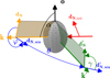 |
Fig. 1 Geometry of a scattering event used for the analytical validation in Sect. 4. A photon arrives from the right side of the grain with some initial north direction dN,init (red). Grain symmetry axis o and angle of incidence α are shown in black. The photon package initial direction k, the plane of incidence, and the north direction in the frame of the grain dN are shown in orange. Scattering angles θ and φ and north directions dN,sca, |

3.3 Propagating the photon package
The polarization of a photon changes when traveling through a dichroic or biréfringent medium. To mathematically describe this, we considered a beam of light propagating through such a medium. Without dust emission or scattering, the polarized RT Eq. (9) simplifies to
 (15)
(15)
As we assume that the density, grain orientation, and the optical properties within a single dust cell are constant, this linear differential matrix equation can be solved analytically within each individual cell. Using Eq. (8) we obtained two coupled systems, and their solution is (Lucas 2003; Whitney & Wolff 2002)
 (16)
(16)
The equation describes the change of the Stokes vector when the photon travels through a single cell in a dichroic or birefringent medium. The change of the Stokes vector S(s) needs to be considered in MCRT computation when the photon packets propagate by s in such a medium. We note that whenever the photon package entered a new cell where the grain orientation is different, we needed to apply a reorientation of the Stokes vector (Sect. 3.2) before we could continue the propagation.
3.4 Optical depth and path length
One necessary exercise in the MCRT treatments is computing the optical depth along the flight path of the photon package through the cell in order to determine whether and where it will interact with the dust. In MCPOL, the grid cells are cubes with a constant density n, and grains have a fixed alignment. The flight path of the photon packets goes along a straight line from the entry point into a cube up to either the interaction point or, in case of no interaction, up to the exit point of that cube.
Photon packets of unpolarized light in a nondichroic medium travel the distance from the entry point of a cube to the interaction point ∆s corresponding to an optical depth τ(∆s). This optical depth can be computed from a random exponential distribution such that the interaction of the photon package with dust in a cell follows a uniformly distributed random number ξ (Krügel 2008; Witt 1977; Lucy 1999; Steinacker et al. 2013),
 (17)
(17)
The optical depth along ∆s is
 (18)
(18)
In comparison to the unpolarized light, the photon packets of polarized light in a dichroic medium travel the distance from the entry point of a cube to the interaction point ∆spo1 and corresponding optical depth τpo1(∆spo1). We added the suffix “pol” for quantities that depend on polarization. Following Baes et al. (2019), a direct connection between the physical path length and the optical depth as given for unpolarized light was lost in media with dichroism and birefringence. Considering polarization in a dichroic medium, the optical depth cannot be calculated in a closed form as in Eq. (18). Diminishing of the polarized radiation needs to consider the change of the Stokes vector S when the photon packet travels through that cell and follows Eq. (16). In that solution, there are additional terms of the Stokes components noted between the brackets beside the extinction given by an exponential decay. We visualize in Fig. 2 that dichroism indeed complicates the relation between path length and optical depth. We chose two examples of the exact solution for polarized light of Eq. (16), adopting qo = Qo/Io = 0.5 and qo = −0.1, and we show the solution for unpolarized light given by exp (−τ). For better visualization, an extremely dichroic cell was adopted, with n = 0.0015, Cext = 1000, and Cpol = 300 (a.u.); hence, the extinction optical depth τ(1) = 1.5. We note that there are large differences between the interaction points ∆s and ∆spo1 calculated using the same optical depth, either τ or τpol, at the same random number ξ. The interaction points are at ∆spo1 = 0.47 for qo = 0.5, at ∆spo1 = 0.57 for qo = −0.1, and at ∆s = 0.54 for unpolarized light (Fig. 2).
To stress the fact that we dealt with dichroic extinction, we used the term polarization optical depth τpo1. We used the definition of an optical depth and inserted Eq. (16)
 (19)
(19)
 (20)
(20)
Except for special cases, the right-hand side of Eq. (20) cannot be simplified. For nonspherical dust particles, there is another complication regarding the orientation of the Stokes vector to the grain orientation. Hence, the dust cross sections needed to be considered. In MCPOL, the grain alignment in a cell is fixed, which simplifies computation of the angle of incidence α, which is the angle between the Stokes vector of the incoming photon and the grain orientation (Fig. 1). The Stokes vector of the incoming photon needs to be rotated to the plane of incidence, and Cext(α) and Cpol(α) are computed for that α. For clarity, the angle and frequency dependence was dropped in Eq. (20).
When taking dichroism into account, the polarization state changes along the flight path of the photon (Sect. 3.3), and an analytical solution for ∆spo1 does not exist. Baes et al. (2019) showed that the solution can be expressed by a Taylor expansion and that the extinction optical depth τ (i.e., the optical depth ignoring polarization) approximates the polarization optical depth τpo1 to the first order, hence
 (21)
(21)
The density n of the cube, the angle of incidence α, and Cext(α) are known. As indicated by the horizontal line in Fig. 2, the same optical depth for unpolarized and polarized light are chosen by the same random number, −1n(ξ) = τ(∆s) = τpo1(∆spo1), which leads to different path lengths ∆s ≠ ∆spo1. The distance ∆s is derived by inserting the quantities n, Cext, and τ(∆s) = −1n(ξ) into Eq. (17). This allows for the computing of τpo1(∆s) using Eq. (20). Hence, we derived the path length of the polarized light
 (22)
(22)
In the magnified examples of Fig. 2, the approximation of ∆spo1 (Eq. (22)) is within 0.3% of the correct solution. For typical ISM dust, Cpol is about a factor 100 smaller (Siebenmorgen 2023), and the uncertainty in ∆spo1 is below 10−4. Whenever possible, the grid in MCPOL is set up so that the total extinction optical depth of a cube or a sub-cube, when needed, is about τ ≲ 1. Radiation penetrating through a highly optically thick medium is challenging for MCRT codes (e.g., Min et al. 2009; Siebenmorgen & Heymann 2012; Gordon et al. 2017; Camps & Baes 2015). The MC applications that consider polarization treatments at path length τpo1 ≫ 1 can progressively solve the RT equation along the ray in each cube, as outlined by Baes et al. (2019). However, this results in an extraordinary increase in computing time and is not considered.
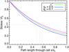 |
Fig. 2 Change of Stokes intensity along a flight path of a photon along a cell. The decay of the intensity is shown for unpolarized light (green) and polarized light (Eq. (16)) with qo = Qo/Io = 0.5 (blue) and qo = −0.1 (magenta). The interaction points of light with dust for random incidence ξ = 0.45 are indicated by the gray lines. |
3.5 Dust albedo of polarized light
When the radiation interacts with a dust grain, it is either scattered or absorbed. The ratio of scattered over extincted intensity defines the albedo Λ. We rotated the Stokes vector so that its component U = 0, applied Eqs. (6)–(8), and derived the albedo of a spheroid including polarization,
 (23)
(23)
This equation can be seen as a more general form of the albedo. For unpolarized radiation or if the polarization scattering cross section and the dichroism cross section are zero, Eq. (23) reduces to its common form. We also note that Eq. (23) is independent of Ccpol. This is consistent with the physical meaning of Ccpol, as it describes a differential phase shift (i.e., a delay) between the north and east polarized parts of the radiation. Such a delay does not reduce the intensity of the radiation.
3.6 Sampling the scattering Müller matrix
In the case of nonpolarized MCRT, simulating a scattering event is relatively straightforward. It essentially comes down to generating a random scattering angle θ from the scattering phase function Φ(θ). Based on the original propagation direction k of the photon package, this scattering angle can be converted into a new propagation direction k′, and this direction describes the scattering event. In polarized MCRT, computing a scattering event is more complicated. Not only is the random generation of a new propagation direction more complex, but the polarization status and the reference direction of the photon package must be updated.
Rather than a single scattering angle, a new pair of angles (θ, φ) must be determined. In this pair, θ is still the scattering angle, that is, the angle between the original propagation direction k and the new propagation direction k′. The angle φ is the azimuth of k′ in a coordinate system with k as the polar direction and the north direction as the reference direction with azimuth zero.
The appropriate probability distribution from which the random couple (θ, φ) needs to be generated is
 (24)
(24)
where
 (25)
(25)
This formula shows two characteristics. Firstly, the probability density function is a true bivariate distribution that depends explicitly on θ and φ in a nontrivial way. Secondly, it depends not only on the characteristics of the dust grains and the grain alignment but also on the polarization state of the photon package. To generate a random couple (θ, φ) from the bivariate probability distribution function of Eq. (24), we used the rejection sampling method (Von Neumann 1951). This method is comparatively simple and is readily applicable to multivariate probability density functions (Devroye 2013; Baes & Camps 2015). A scattering angle pair(θ, φ) is generated and accepted if a third random number ξ3 is lower than the probability P(θ, φ) of scattering in this particular direction (Fig. 3). A ceiling value υcei1 gives the maximum probability for any of the angles and is used to scale the third random number. The actual implementation begins with calculating two scattering angles based on uniform deviates ξi,
 (26)
(26)
 (27)
(27)
Importantly, we note that we uniformly sampled in θ, which means that we sampled more angles per surface area in the forward and backward directions. This was motivated by the fact that dust grains preferably scatter forward or backward. The sampling density had to be taken into account when we calculated the probability of scattering in the direction θ, φ. We calculated a ceiling value υceil, which is representative for the highest probability of scattering toward a direction φ, θ. Following Eq. (3), with the scattering matrix Z, the outgoing intensity I′ for an incoming photon with the Stokes vector S is
![Mathematical equation: ${\upsilon _{{\rm{ceil}}}}\, = \,\max \,\left[ {I\prime \left( {\theta ,\varphi } \right)\,\sin \theta } \right],$](/articles/aa/full_html/2023/05/aa42539-21/aa42539-21-eq30.png) (28)
(28)
![Mathematical equation: $ = \,\max \,\left[ {\left( {{Z_{11}}I\, + \,{Z_{12}}Q\, + \,{Z_{13}}U\, + \,{Z_{14}}V} \right)\sin \theta } \right],$](/articles/aa/full_html/2023/05/aa42539-21/aa42539-21-eq31.png) (29)
(29)
with Zij(λ, α, φ, θ) as the elements of the scattering matrix. The factor sin θ compensates for oversampling of the forward and backward regions and reduces the ceiling value υceil. The ceiling value needs to be recomputed for each scattering event where the Stokes parameters Q, U, and V; the angle of incidence α; or the wavelength λ change. The decision of whether the angle pair is accepted is based on the third random number,
 (30)
(30)
with 0 ≤ ξ3 ≤ 1. The angles φ and θ are accepted, if
 (31)
(31)
A low ceiling value υceil, increases the probability that an angle pair is accepted. Our method of changing the sampling density used a simple approach to reduce the average number of draws until a pair was accepted. There are more sophisticated methods utilizing the scattering behavior of the dust mixture used in the simulations.
After generating a random angle pair (θ, φ), we needed to update the characteristics of the photon package. The obvious characteristic to update was the propagation direction. The new propagation direction after scattering was calculated following Eq. (30) of P17,
 (32)
(32)
The polarization state of the photon package also needed to be updated since the scattering event affects the state. The new Stokes vector became
 (33)
(33)
where the factor between the brackets guarantees that the total intensity of the photon package is conserved during the scattering event. Finally, the east direction was also updated. The convention we used required that the new north direction be in the plane of departure after scattering. This plane is given by the direction after scattering k′ and the symmetry axis of the grain o, similar to the plane of incidence. Therefore, the east direction after scattering is
 (34)
(34)
If the outgoing direction and the symmetry axis are parallel or antiparallel, the photon package continues its path through the model space without the need to rotate the Stokes vector.
 |
Fig. 3 Visualization of the rejection sampling method. An arbitrary probability density function P(θ, φ) is shown in blue, and the ceiling value υcei1 is in yellow. An angle pair (θ, φ) is accepted if a third (0, υcei1) is smaller than P(θ, φ). For two-angle pairs, the segments in green and red visualize the ζ value leading to acceptance or rejection, respectively. The case where the green line is longer has a higher chance of being selected than the other case where the green line is shorter. For the selected case of the longer green line, P(θ, φ) becomes much larger than in the other case, as is expected. |
3.7 Detection of escaped photons
Eventually, the photon packages leave the model space. We recorded their exiting directions k and wavelengths. Photons that exited with the same wavelength and with similar angles to the simulation z-axis were binned together. For axisymmetric geometries, this method allowed for the quick calculation of the spectral energy distribution of the model under different viewing angles. The Stokes vector of the photon packages was rotated upon exit such that north was in the plane given by the escape direction and the z-axis of the model space. This permitted binning of the photon packages by adding their Stokes vectors and intensities.
3.8 Directed scattering (peel-off)
The MCRT codes commonly allow for viewing of the model space from (arbitrary) directions kobs. This simulates an observation by a distant observer. The chance of a photon scattering directly toward the observer is low. We therefore employed the peel-off method (Yusef-Zadeh et al. 1984) in which the probability of scattering toward the observer is calculated explicitly. During the model run for all scattering events, we stored the position, direction k, and Stokes vector S of the photon packages before scattering. After the simulation finished, we used the scattering matrix Z to calculate the Stokes vector Sobs of the radiation that would have scattered toward kobs,
 (35)
(35)
where  is used as a normalization factor (see below) and φobs and θobs are the angles by which the photon is scattered toward the observer. The scattering angle θobs was calculated from the direction before and after scattering,
 (36)
(36)
And the azimuth φobs from the east direction dE and the normal to the scattering plane were calculated from k and kobs,
 (37)
(37)
 (38)
(38)
The normalization  of the scattering matrix is essential for calculating the peel-off probability using Eq. (35). The scattering matrix was stored internally as a multidimensional array with Nθ and Nφ elements along the respective angles (θ, φ). Following Eq. (6), the sum of the Z11 elements over the unity sphere is Nθ Nφ Csca. As the scattering probability had already been considered during the MC run, we divided by Csca.
The intensity of the radiation that was scattered toward the observer was the first component of the Stokes vector resulting from Eq. (35). The intensity of the radiation that would reach the observer had to be reduced to account for (dichroic) extinction between the point of scattering and the observer. To apply this properly, we developed an inverse ray-tracing routine, which is discussed in the following section.
3.9 Inverse ray-tracing
An inverse ray tracer was developed to calculate the spatially resolved maps of the model space. For the ray tracer, it was necessary to know the optical depth of the scattering event toward the observer. We computed a Stokes map by sending rays in the direction −kobs from the observer to an area of the model. Along the path of a ray, the ray encounters cells that are numbered by i = 1, …, m. For each cell, we calculated the amount of radiation Ii that would be scattered and emitted toward kobs and attenuated this according to the optical depth τout from the present position to the entry point of the ray in the model space. The map was created by varying the position at which the ray enters the model and under the assumption that the complete model space was sampled (Heymann & Siebenmorgen 2012).
Without considering polarization, the intensity of the radiation leaving the simulation was determined by the optical depth to the edge of the model space, τout. By stepping through the system along −kobs, the optical depth increased. The ray crossed the cells 1, …, m, and in each cell i, the optical depth to the edge increased by the product of the extinction cross section of the dust Cext,i, its density ni, and the path length (∆s)i,
 (39)
(39)
The radiation that was scattered or emitted in cell i toward the observer with an intensity Ii, exited the model and reached the observer with the reduced intensity  .
.
When we took dichroism into account, the optical depth through cell i depended on the polarization of the radiation. In addition, the polarization of the radiation changed along kobs. Both effects are described by Eq. (16). We also had to consider the orientation of the grains, as they can be different for each cell. The Stokes vector S of the photon package changes on its way from cell i along direction kobs out of the model space. The change is given by an initial rotation into the frame of the cell, R, then an alternating application of a dichroic extinction step toward the edge of that cell followed by a rotation into the plane of incidence of the next cell and so forth until the photon package eventually leaves the model space. This can be written as a single equation by combining Eq. (16) and Eq. (4):
 (40)
(40)
For each cell j with 0 ≤ j ≤ i, the rotation into the cell j − 1 is Rj, and Robs is the rotation of north into the reference frame of the observer. The optical depth inside j is τext,j = Cext,j nj (∆s)j, and the dichroism and birefringence matrix is Ej,
 (41)
(41)
where for cell j, the dichroism and birefringent optical depths are given by
 (42)
(42)
 (43)
(43)
The ray-tracing equation, Eq. (40), assumes that the photon package is emitted or scattered at the edge between the cell i and cell i + 1. This is correct for optically thin cells (τ < 0.1). In the case of optically thicker cells, the emission is distributed along the path in cell i and needs to be integrated within cell i.
The advantage of Eq. (40) is that it can be evaluated while stepping along the pencil beam. Additionally, the product of the matrices of the previous cells is sufficient to calculate the Stokes vector of the next cell. For cell i, the matrix of the previous cell i − 1 is multiplied by  . One can also store the compound matrix that is updated when entering the next cell. Finally, the compounded exponential factor of Eq. (40) can be stored separately to keep the entries of the matrix closer to unity and to prevent numerical instabilities.
4 Validation
The MCRT codes need to be carefully validated. To do so, one can often use benchmark results from existing codes for comparison. However, as scattering, dichroism, and birefringence due to spheroidal dust grains are uncommon capabilities for MCRT codes, there are no such benchmarks to reproduce. In an ideal benchmark, the different functionalities are tested individually. Such a procedure simplifies the identification of potential shortcomings or even mistakes, and it enables codes with different sets of functionalities to reuse the same tests.
As advocated by P17, it is particularly advantageous to compare the results of our implementations to analytical solutions. Analytical solutions are easy to reproduce and can be used to estimate the errors of the numerical treatment. Analytical solutions are also of interest to other teams aiming to verify their MCRT codes. In this section, we develop analytical test cases to verify our numerical implementation of scattering, dichroism, and birefringence due to spheroidal dust. The MCRT treatment of scattering by spheroidal dust (Sect. 4) is confirmed using renewed versions of analytical test cases by P17 developed for spherical grains. Additional analytical test cases for estimating the numerical accuracy of MCRT codes that are treating dichroism and birefringence mechanisms are presented in Sect. 5.4.
In P17, we considered radiation scattering on spherical grains and developed several test cases to validate the numerical procedure for solving this RT problem of polarized light. The analytic solutions can only be expressed exactly because single scattering in a simplified geometry was considered (Fig. 4) and electrons with their uncomplicated Müller matrix were applied. Four test cases (TCs) are distinguished with analytical solutions given by P17 (Eqs. (44)–(63)). Circular polarization was not considered in TC 1–TC 3 (V = 0) but is treated in TC 4.
In the first TC scenario, a central point source emits unpolarized radiation. To test the peel-off scattering procedure, we selected two slabs of electrons. The photons scattered once at these optically and physically thin electron slabs that lie on the xy plane. A distant observer recorded the intensity, polarization degree, and polarization angle of the radiation scattered off the slabs. TC 1 verifies the polarization by single scattering and the peel-off mechanism.
In the next test scenarios (TC 2–TC 4), the central light source was replaced by a tiny cloud of electrons, and they were illuminated by a collimated beam. The analytical solutions of P17 were derived for photons that encounter a first scattering event at the center and a second scattering event at the slabs (Fig. 4).
In the second test case, TC 2, the direction of the collimated beam was in the same plane as the direction of the slabs. The second scattering was from the electron slab to the observer. In this configuration, scattering and the peel-off mechanism as well as a random walk step of the photons were tested.
In the third test case, TC 3, the initial beam direction was at an angle to the plane of the slabs. The plane of scattering of the initial scattering was rotated to the plane of scattering off the slabs. The rotation led to a variable polarization angle at the observer.
In the final test case, TC 4, the scattering properties of the particles were changed. The Müller matrix of the electrons was hypothetically changed so that radiation scattering on them could become circularly polarized. In particular, M34 ≠ 0 and M43 ≠ 0 (Eq. (3)), which are zero for electrons.
We expanded the test scenarios of P17 to cover the case of scattering at spheroidal dust particles. For spheres and sphere-like particles, the scattering matrix is most simple when north is in the scattering plane before and after the scattering event. In that case, the scattering matrix Z reduces to a block diagonal shape, which for electrons depends only on the scattering angle θ and is independent of φ, hence
 (44)
(44)
The geometry and our notation of the scattering process on spheroidal grains is shown in Fig. 1 and summarized in Table A.1. In contrast to spheres, for spheroidal particles, the scattering matrix is usually given for north in the plane of incidence before the scattering event and for north in the plane of departure after the scattering event.
In the test cases for spheroidal grains, we used spherical grains that were treated in the computations as if they were spheroids. Therefore, an orientation о was artificially assigned to these spherical grains. The orientation о can either be fixed or even chosen at random without altering the result of the scattering computation. In addition, the scattering matrix of the spheres was multiplied by two rotation matrices R to account for the different orientations of the north direction during the scattering process on spheroidal grains. These two rotations describe the change of the north direction from the plane of incidence to the plane of scattering by the angle φ and the rotation from the plane of scattering to the plane of departure by the angle γ (Fig. 1). The scattering matrix Zsph of the artificially assigned orientation of spherical particles is therefore
 (45)
(45)
 (46)
(46)
where x = cos 2γ, у = sin 2γ, p = cos 2φ, and q = sin 2φ. The angle γ was calculated using the angle of incidence α and the scattering angles θ and φ, as described in Appendix A.
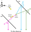 |
Fig. 4 Geometry of the analytical test cases. The z-axis is oriented toward the reader and −y toward the observer. TC 1: a central point source illuminates thin slabs of electrons that are slanted 45° toward the observer. For the other test cases, the central point source is replaced by a small cloud of electrons. TC 2: the cloud is illuminated by a collimated beam, which is located in the xy plane. TC 3-TC 4: the illuminating source is located below the xy plane. |
5 Results
5.1 Numerical setup
We verified the numerical treatment of the analytical test cases TC 1–TC 4 as implemented in MCPOL, while P17 verified them using SKIRT. The MC treatments of both codes differ in many aspects. In SKIRT, various acceleration methods, such as forced scattering and forced absorption, are included that are not implemented in MCPOL. In SKIRT (Camps & Baes 2015), a simplified Stokes formalism is used, which is derived from assuming spherical particles, whereas MCPOL treats spheroidal-shaped particles. Different vectorization technologies are used in SKIRT and MCPOL, and the model grids in both codes are also different. For their test cases, P17 used a grid of (601, 601, 60) cuboids with each having a length of (0.003, 0.003, 3 × 10⁻⁷) in arbitrary units, and for each cube, an electron cloud with an optical depth of τ = 10−3 was included. The MCPOL code uses a Cartesian coordinate system with cubes that can be divided into sub-cubes. For the test cases, we found a good MCPOL setup using (587, 587, 3) cubes with a side length of one for each cube. The cube in the center and the cubes of the slabs were filled by electrons at an optical depth of τ = 0.5, other cubes were free of electrons and had τ = 0. Hence, the probability of multiple scattering events in cells filled with electrons was unlikely but not zero. Photons that scattered a second time, either at the center or at the slabs, were ignored so that the numerical results could be compared with the analytical solutions. Therefore, the choice of τ was done with some care. A too-low value of τ reduces the scattering probability of the photons, while an increase of τ enhances the chance of multiple scattering and leads to photons that must be ignored.
The number of photon packets launched, unless otherwise stated, was Nγ = 2.5 × 10¹⁰. Results from decreasing or increasing the number of emitted photon packets and applying different sampling of the model space are discussed in Sect. 5.3. We repeated test cases TC 1–TC 3 of P17 using the scattering matrix Zsph and pretending that sphere-like grains had an orientation and therefore needed to be treated as spheroids. We chose the grain orientation along +êz.
5.2 Test cases 1–4
We compared the numerical results of MCPOL for the TCs 1–4 against the analytical solutions provided in Eqs. (44)–(63) by P17. The results are plotted in Figs. 5 and 6. The instrumental position x of the detector determines the scattering angle θ (see Fig. 4) through the relation derived in P17,
 (47)
(47)
The left column of Fig. 5 shows the results of the first test case (TC 1). The result of MCPOL jitters around the analytic solution. The middle graph shows the linear polarization degree computed using Eq. (3) in P17. The MCPOL code reproduces the analytic solution of TC 1 to better than ±0.1%rel. We attributed the residual deviations to sampling errors in the initial direction of the photons from the source and the finite size of the model grid. The analytical curves were calculated for an infinitesimal “height” of the slabs. In the numerical treatment, the photon packages that arrived at a given detector pixel took paths with a small but finite height. In the outer parts (‖x‖ > 0.3), these paths led to a lower average polarization degree. In the inner parts (‖x‖ < 0.3), they led to a higher average polarization degree. In the bottom graph of the left column, the polarization angle computed using Eq. (4) in P17 is compared to the analytic result, which is 0°. Here, MCPOL deviates from the analytical result in the very central region (‖x‖ < 0.1). Such inaccuracies cannot be avoided and are expected to be due to the setup of the numerical grid, namely, the finite height of the slabs, and the amplification of the noise for polarization degrees close to zero.
The middle column of Fig. 5 shows the result of the second test case (TC 2). The intensity curve includes the noise of several percent and is higher than the curve in TC 1. This is because the chance of scattering at the central cell is lower than unity. Some photons did not scatter, so fewer photons propagated toward the slabs. This led to a lower photon count at the detector. The polarization degree for TC 2 is correct to 0.1%rel (Fig. 5). As in the case of TC 1, we attributed the remaining differences to the resolution of the grid. The analytic solution of the polarization angle was zero and is shown together with the numerical solution by MCPOL at the bottom of Fig. 5.
The right column of Fig. 5 shows the result of the third test case (TC 3). The intensity curve is plotted in the first row. The model results follow the analytic solution. The noise in the numerical solution is comparable to the noise found in TC 2 and has the same explanations. The polarization degree derived by MCPOL for TC 3 is correct to well below 0.2%rel. As we noted in P17, the area around 0.6 ≤ ‖x‖ ≤ 0.7 is very difficult to treat with high precision. In this area, the scattering angle from the initial direction to the slabs changes only by 0.1°, whereas the polarization degree changes by ~40%abs. The scattering matrix was tabulated for integer scattering angles and was linearly interpolated for non-integer scattering angles. This comparatively sparse sampling is sufficient to calculate the correct result. In comparison to P17, we even attained greater precision. We attribute this to the fact that the scattering matrix for spheroids not only contains the scattering but also the rotations of the plane of scattering. In P17, we calculated the effect of the plane rotations separately. Variations of the polarization angle are shown in the third row of Fig. 5. The MCPOL code applied to this test case followed the analytic result to the high precision of 0.1%rel.
Scattering at electrons did not lead to circular polarization, as d(θ) = 0 in Eq. (44). In P17, we introduced a hypothetical particle for which
 (48)
(48)
 (49)
(49)
Otherwise, these test particles behave as electrons. Such particles lead to circular polarization. They were applied in TC 4, which uses the geometry of TC 3. In Fig. 6, the results of TC 4 are displayed for MCPOL launching the large number of Nγ = 2.5 × 10¹¹ photon packets. The intensity, the reduced Stokes parameters Q/I and U/I, the linear polarization degree, the polarization angle, and the circular polarization expressed as V/I are shown. The MCPOL code reproduced the analytic solutions of the Stokes parameters of TC 4 at high precision as well as those for the circular polarization to better than 0.03%rel.
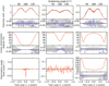 |
Fig. 5 Test cases 1 through 3 using the spheroid-like Müller matrix (Eq. (46)) with the assumed particle orientation along the z-axis. The different rows show the intensity (top row), linear polarization degree (middle row), and polarization angle (bottom row) of the observed radiation. The analytical solution is shown in black and the model results in orange. The bottom panels present the absolute differences (blue) and relative differences (shaded area) between the analytic solution and the model. The magnitude of the shaded area is given in every panel. |
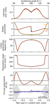 |
Fig. 6 Circular polarization test case from P17 using the spheroidlike Müller matrix (Eq. (46)) with assumed orientation of the particles along the z-axis. We show the intensity I, Stokes U/I and Q/I, the linear polarization degree and angle, and the circular polarization V/I. The analytic solution is indicated by the dashed lines in black and the MCPOL model results in red and orange. For the circular polarization we also plot the difference from the analytical solution in the lower panel. The absolute difference is shown in blue and a relative difference of σ (∆(x)) = ±3 × 10⁻⁴ (Eq. (50)) is shaded in grey. |
Precision of MCPOL for TC 4 tested by varying the number of sub-cubes and emitted photons..
5.3 Numerical precision
The precision of MCPOL was exemplified by varying the number of sub-cubes Nsub of cells along the x, y, and z coordinates and the number of emitted photons Nγ in computations of circular polarized light. The difference between the numerical model V/IMCpol and the analytical solution V/Iana (P17) was computed for the reduced Stokes parameter of the circular polarized light in TC 4
 (50)
(50)
The minimum, maximum, and standard deviations σ of that difference ∆ are given for the parameter variations in Table 1. For the minimum number of emitted photons (Nγ = 2.5 × 10⁹), an increase of Nsub from one to three did not improve the 1σ noise in the model. When launching ten times more photons, the noise in the model without sub-cubes (Nsub = 1) remained unchanged, whereas it improved by a factor of two for the Nsub = 3 and by almost a factor of four for the Nsub = 11 model. In models without sub-cubes, the location of the first scattering event (i.e., the blob of electrons in the center of the model space) was not well sampled. This caused a systematic error in backward scattering (θ ~ 180°) at x ~ 0. The effect was reduced by increasing the number of sub-cubes, and for Nsub = 11, it decreased to Δ (x ~ 0) < 10−3, as shown in the bottom panel of Fig. 6. Even for our choice of optically thin cubes, the detailed fine sampling impacted the precision that could be reached, and the precision could not be improved by simply increasing the photon statistics (Table 1). Obviously, with an even finer grid and more photons, the precision of MCPOL could be further improved, at the expense of significantly increased computational cost. In our server environment, the latter model took (already) ~200 h. Both codes show similar run times to reach similar precisions.
5.4 Dichroism and birefringence
In addition to the polarization due to scattering, we had to confirm the implementations of polarization due to dichroism and birefringence. For this, a spherical distribution of dust with density n and radius r around a central source were considered. The test was performed using hypothetical dust particles that dichroically absorb and slow radiation but do not scatter. The dust is tailored to remove any side effects from the scattering implementation. The hypothetical dust particles were chosen to be analytically simple,
 (51a)
(51a)
 (51b)
(51b)
 (51c)
(51c)
 (51d)
(51d)
 (51e)
(51e)
The angle α is the angle of incidence (Fig. 1), and the sine and cosine make it such that the transition is smooth for the sight lines around α = 0. When initially right-handed circular polarized radiation, S = (1, 0, 0, 1), travels through the dust cloud, its direction and the grain orientation have a constant angle of incidence α. Following Eq. (16), upon leaving the simulation area, the Stokes vector of the photon package is
 (52)
(52)
We note that in this scenario, the Stokes vector depends only on α. The analytic solutions for the reduced Stokes parameters are,
 (53a)
(53a)
 (53b)
(53b)
 (53c)
(53c)
 (53d)
(53d)
under the different viewing angles α toward the z-axis. We used this closed form to validate the implementation of dichroism and birefringence in MCPOL.
In Fig. 7, we compare the results of MCPOL with the analytic solutions. In the top panel, the observed Stokes parameters are plotted, using lines for the analytic solution and symbols for the numerical results achieved by MCPOL. The lower panel gives the relative error between the numerical and analytical solutions. As we binned the exiting photons using the cosine of their exit angles, there are more data points for large viewing angles than for small viewing angles. Generally, the analytic solution is reproduced to better than 5%rel. There are a few aliasing effects at 18°, 33°, 42°, and 61°, and U/I shows slightly more noise. We attributed this to sampling errors caused by the finite resolution of the grid.
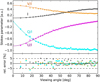 |
Fig. 7 Dichroism and birefringence test case. Intensity I (black), reduced Stokes Q/I (cyan), U/I (magenta), and circular polarization V/I (orange) for different viewing angles. Analytic solutions (Eq. (53)) are represented by lines and MCPOL results by symbols. The relative error of the numerical run against the analytic solution is shown in the bottom panel using the same color code. |
5.5 Albedo test case
The final test confirms the correct implementation of the albedo. The albedo of spheroids and spheroid-like particles depends on the polarization of the radiation interacting with the grains. The MCPOL code handles this interaction by using Eq. (23). The albedo connects the effects of scattering and extinction, and a test of the implementation must consider both effects simultaneously.
We set up a test in which a collimated beam of right-handed circular polarized radiation propagates along an elongated dust cloud of length r. The dust cloud dichroically extinguishes and scatters the radiation. The orientation о of the dust particles is perpendicular to the beam (α = 90°, Fig. 1), and no radiation scatters into the beam. The geometry of the albedo test case is illustrated in Fig. 8. We used an artificial dust grain that scatters isotropically while preserving the Stokes parameters. Mathematically, such a particle is obtained by using the 4D unity matrix as the scattering matrix,
 (54)
(54)
The cross sections are similar to the previous test (Eq. (51)), but in this case the scattering cross sections differ from zero:
 (55a)
(55a)
 (55b)
(55b)
The Stokes vector along 0 ≤ s ≤ r in radial direction r of the dust cloud before scattering is
 (56)
(56)
As the beam is collimated, the inverse square law does not apply here. The scattering probability is given by Eq. (6),
 (57)
(57)
The Stokes components of the radiation arriving at the detector are given by multiplying  with S(s),
 (58a)
(58a)
 (58b)
(58b)
 (58c)
(58c)
 (58d)
(58d)
The change of the Stokes components can be illustrated as follows: The component of the radiation that is polarized parallel to the orientation о of the grains (out of the plane of the paper in Fig. 8) is more strongly extincted than the component perpendicular to o. Along the path through the dust cloud, the remaining radiation is more polarized in the plane of the paper, hence Q < 0. Following Eq. (58d), the circular polarization degree V/I decreases along s (Fig. 8). As the incidence of the radiation is perpendicular to the alignment (α = π/2), the phase between the two components stays constant (Ccpol = 0), and the circular polarization does not turn into linear polarization (U ≡ 0).
In Fig. 9, we show the results of the albedo test case solved by MCPOL along with the analytic solutions. The intensity decreases by ~20% along the profile of the dust cloud. The circular polarization degree (V/I) of the radiation decreases from one to about 0.27. These effects follow the analytic expectation with high precision, and the relative error is below 0.3%. In summary, MCPOL reproduces the correct behavior of the analytic solution of the albedo test case, and the numerical imprecision of the Stokes vector is low (≲1%).
If the albedo would not favor reflecting radiation polarized perpendicular to the alignment, the reflected intensity would behave very differently. As an example, we show the analytic solution of the intensity for test particles having Csca,pol = 0. In that case, the total intensity of the beam decreases exponentially, as often applied in astronomy.
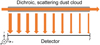 |
Fig. 8 Geometry of the albedo test case. A collimated beam passes along s from zero to r through a dichroic dust cloud. Some of the photons are scattered to a detector. The alignment of the dust grains о is pointing out of the page, towards the reader, and is perpendicular to the beam, α = 90°. |
6 Summary
We implemented polarization of radiation by spheroidal dust considering scattering, dichroic extinction, and birefringence in the MCRT code MCPOL. We provided a detailed description of the selected methodology: Stokes formalism. We developed paradigmatic examples for testing numerical polarization RT models using spheroidal dust against analytical solutions. These examples were used to verify the correct functionality of the MCPOL code, and they may be applied by other teams to verify their codes. Further, the comparison of MCPOL against the analytical solutions provided a means for estimating the numerical precision of the calculated polarization. We found a typical deviation of 0.1% between the MCPOL and the analytical solution regarding the intensity, the linear polarization degree, and angle. The circular polarization showed a deviation of 0.03%. However, at a small angle of incidence α ~ 0 or for backward scattering (θ ~ 180°), we noticed larger deviations that are due to sampling errors caused by the finite size of the applied grid of the model volume.
The analytical test cases are suitable for use by other teams to estimate the precision of their dust polarization treatments. So far, only a limited number of MCRT codes support polarization for particle geometries that are more complicated than spheres. This is despite the fact that extinction due to spheres cannot explain the well-established Serkowski curve (Serkowski et al. 1975) of the diffuse interstellar medium (ISM). We hope that the presented examples with their attached analytical solutions will ease the verification of MCRT codes that treat dust polarization for complex grain shapes, and thus increase the number of available codes.
In realistic applications, one needs to consider more appropriate dust geometries. For example, a starting point could be replacing spherical grain shapes with spheroidal grain shapes. For a mix of such particles made up of different kinds of carbon and silicate materials and spanning a range of particle sizes and grain porosity, their optical cross sections and corresponding scattering matrix would need to be computed. Furthermore, some type of grain alignment would need to be implemented. Using the algorithms presented in this paper, the MCPOL code is now capable of tracing the polarization due to spheroidal dust grains. The MCPOL code we presented and tested is openly available to the community. We are inviting collaborative efforts to apply it and other codes to realistic scenarios.
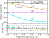 |
Fig. 9 Albedo test case. Elements of the reduced Stokes vector of photons scattered out of a cloud having spheroidal particles with Csca,pol = −0.1. Intensity using spheroids with Csca,pol = 0 is shown as a dashed line. Analytic solutions Eq. (58)) are represented by lines and MCPOL results by symbols. Intensities in black are multiplied by a factor of 11. The rest of the notation is the same as in Fig. 7 and Table A.1. |
Acknowledgements
CP and M.B. acknowledge the financial support from CHARM (Contemporary physical challenges in Heliospheric and Astrophysical Models), a Phase-VII Inter-university Attraction Pole program organized by BELSPO, the Belgian federal Science Policy Office.
Appendix A Calculation of the exit angle
We begin with the vectors of the symmetry axis of the grain o, the propagation direction before scattering k, and the normal to the plane of incidence n. By rotating n around k by φ, we obtained the normal to the scattering plane nscat. Rotating k around nscat by θ results in the propagation direction after scattering k′. The (as of yet unknown) exit angle γ was used to rotate nscat around k′ into the normal of the plane of departure n′. These rotations can be calculated with Euler’s finite rotation formula (Cheng & Gupta 1989) and simplified by taking into account that many pairs of these vectors are perpendicular. With the substitutions cx = cos x and sx = sin x, we can write
 (A.1)
(A.1)
This normal must be perpendicular to the symmetry axis of the grain, o · n′ = 0. This leads to
 (A.2)
(A.2)
which can be solved for γ,
 (A.3)
(A.3)
The arc-tangent function is undefined for 0/0. This happens if either sφ = 0 and α = θ or if sα = 0 and sθ = 0. The first case means that the scattering plane is the plane of incidence (because φ = 0). Therefore, the plane of scattering is the plane of departure as well, γ = 0 (or γ = π). In the second case, the propagation direction before scattering is (anti)parallel to the grain orientation, and the scattering plane will be the plane of departure, again γ = 0.
Notation
References
- Abhyankar, K. D., & Fymat, A. L. 1969, J. Math. Phys., 10, 1935 [CrossRef] [Google Scholar]
- Asano, S., & Yamamoto, G. 1975, Appl. Opt., 14, 29 [NASA ADS] [CrossRef] [Google Scholar]
- Baes, M., & Camps, P. 2015, Astron. Comput., 12, 33 [NASA ADS] [CrossRef] [Google Scholar]
- Baes, M., Peest, C., Camps, P., & Siebenmorgen, R. 2019, A&A, 630, A61 [NASA ADS] [CrossRef] [EDP Sciences] [Google Scholar]
- Bertrang, G. H.-M., & Wolf, S. 2017, MNRAS, 469, 2869 [NASA ADS] [CrossRef] [Google Scholar]
- Bianchi, S., Ferrara, A., & Giovanardi, C. 1996, ApJ, 465, 127 [NASA ADS] [CrossRef] [Google Scholar]
- Bohren, C. F., & Huffman, D. R. 1998, Absorption and Scattering of Light by Small Particles (New York (N.Y.): Wiley-Interscience) [CrossRef] [Google Scholar]
- Camps, P., & Baes, M. 2015, Astron. Comput., 9, 20 [Google Scholar]
- Camps, P., & Baes, M. 2020, Astron. Comput., 31, 100381 [NASA ADS] [CrossRef] [Google Scholar]
- Chandrasekhar, S. 1960, Radiative transfer (New York: Dover) [Google Scholar]
- Cheng, H., & Gupta, K. 1989, J. Appl. Mech., 56, 139 [NASA ADS] [CrossRef] [Google Scholar]
- Chira, R. A., Siebenmorgen, R., Henning, T., & Kainulainen, J. 2016, A&A, 592, A90 [NASA ADS] [CrossRef] [EDP Sciences] [Google Scholar]
- Contopoulos, G., & Jappel, A., 1974, Transactions of the IAU, 15B (Springer Netherlands), 166 [Google Scholar]
- Devroye, L. 2013, Non-Uniform Random Variate Generation (Springer New York) [Google Scholar]
- Draine, B. T. 1988, ApJ, 333, 848 [NASA ADS] [CrossRef] [Google Scholar]
- Draine, B. T., & Flatau, P. J. 1994, J. Opt. Soc. Am. A, 11, 1491 [NASA ADS] [CrossRef] [Google Scholar]
- Draine, B. T., & Hensley, B. S. 2021, ApJ, 919, 65 [NASA ADS] [CrossRef] [Google Scholar]
- Fleck, J. A., Jr., & Canfield, E. H. 1984, J. Comput. Phys., 54, 508 [NASA ADS] [CrossRef] [Google Scholar]
- Forrest, W. J., Gillett, F. C., & Stein, W. A. 1975, ApJ, 195, 423 [NASA ADS] [CrossRef] [Google Scholar]
- Goosmann, R. W., & Gaskell, C. M. 2007, A&A, 465, 129 [NASA ADS] [CrossRef] [EDP Sciences] [Google Scholar]
- Goosmann, R. W., Gaskell, C. M., & Marin, F. 2014, Adv. Space Res., 54, 1341 [NASA ADS] [CrossRef] [Google Scholar]
- Gordon, K. D., Baes, M., Bianchi, S., et al. 2017, A&A, 603, A114 [NASA ADS] [CrossRef] [EDP Sciences] [Google Scholar]
- Hamaker, J., & Bregman, J. 1996, A&AS, 117, 161 [NASA ADS] [CrossRef] [EDP Sciences] [Google Scholar]
- Harries, T. J. 2000, MNRAS, 315, 722 [NASA ADS] [CrossRef] [Google Scholar]
- Heymann, F., & Siebenmorgen, R. 2012, ApJ, 751, 27 [NASA ADS] [CrossRef] [Google Scholar]
- Ivezic, Z., Groenewegen, M. A. T., Men’shchikov, A., & Szczerba, R. 1997, MNRAS, 291, 121 [NASA ADS] [CrossRef] [Google Scholar]
- Kataoka, A., Muto, T., Momose, M., et al. 2015, ApJ, 809, 78 [Google Scholar]
- Krügel, E. 2008, An Introduction to the Physics of Interstellar Dust (IOP) [Google Scholar]
- Krügel, E. 2009, A&A, 493, 385 [NASA ADS] [CrossRef] [EDP Sciences] [Google Scholar]
- Krügel, E. 2015, A&A, 574, A8 [NASA ADS] [CrossRef] [EDP Sciences] [Google Scholar]
- Lee, D. H., Seon, K. I., Min, K. W., et al. 2008, ApJ, 686, 1155 [NASA ADS] [CrossRef] [Google Scholar]
- Lucas, P. 2003, J. Quant. Radiat. Transf., 79, 921 [CrossRef] [Google Scholar]
- Lucy, L. B. 1999, A&A, 344, 282 [NASA ADS] [Google Scholar]
- Martin, P. 1974, ApJ, 187, 461 [NASA ADS] [CrossRef] [Google Scholar]
- Miller, J. S., & Goodrich, R. W. 1990, ApJ, 355, 456 [NASA ADS] [CrossRef] [Google Scholar]
- Min, M., Dullemond, C. P., Dominik, C., de Koter, A., & Hovenier, J. W. 2009, A&A, 497, 155 [NASA ADS] [CrossRef] [EDP Sciences] [Google Scholar]
- Mishchenko, M. I. 1991, ApJ, 367, 561 [NASA ADS] [CrossRef] [Google Scholar]
- Mishchenko, M. I. 1991, J. Opt. Am. A, 8, 871 [NASA ADS] [CrossRef] [Google Scholar]
- Mishchenko, M. I., Travis, L. D., & Mackowski, D. W. 1996, JQSRT, 55, 535 [CrossRef] [Google Scholar]
- Mishchenko, M. I., Travis, L. D., & Lacis, A. A. 2002, Scattering, Absorption, and Emission of Light by Small Particles (Cambridge University Press) [Google Scholar]
- Montgomery, J. D., & Clemens, D. P. 2014, ApJ, 786, 41 [NASA ADS] [CrossRef] [Google Scholar]
- Pascucci, I., Wolf, S., Steinacker, J., et al. 2004, A&A, 417, 793 [NASA ADS] [CrossRef] [EDP Sciences] [Google Scholar]
- Peest, C., Camps, P., Stalevski, M., Baes, M., & Siebenmorgen, R. 2017, A&A, 601, A92 [NASA ADS] [CrossRef] [EDP Sciences] [Google Scholar]
- Pinte, C., Ménard, F., Duchêne, G., & Bastien, P. 2006, A&A, 459, 797 [NASA ADS] [CrossRef] [EDP Sciences] [Google Scholar]
- Pinte, C., Harries, T., Min, M., et al. 2009, A&A, 498, 967 [NASA ADS] [CrossRef] [EDP Sciences] [Google Scholar]
- Planck Collaboration Int. XIX. 2015, A&A, 576, A104 [NASA ADS] [CrossRef] [EDP Sciences] [Google Scholar]
- Purcell, E. M., & Pennypacker, C. R. 1973, ApJ, 186, 705 [NASA ADS] [CrossRef] [Google Scholar]
- Reissl, S., Wolf, S., & Brauer, R. 2016, A&A, 593, A87 [NASA ADS] [CrossRef] [EDP Sciences] [Google Scholar]
- Robitaille, T. P. 2011, A&A, 536, A79 [NASA ADS] [CrossRef] [EDP Sciences] [Google Scholar]
- Scicluna, P., & Siebenmorgen, R. 2015, A&A, 584, A108 [NASA ADS] [CrossRef] [EDP Sciences] [Google Scholar]
- Seon, K.-I. 2018, ApJ, 862, 87 [NASA ADS] [CrossRef] [Google Scholar]
- Serkowski, K., Mathewson, D. S., & Ford, V. L. 1975, ApJ, 196, 261 [NASA ADS] [CrossRef] [Google Scholar]
- Siebenmorgen, R. 2023, A&A, 670, A115 [NASA ADS] [CrossRef] [EDP Sciences] [Google Scholar]
- Siebenmorgen, R., & Heymann, F. 2012, A&A, 539, A20 [NASA ADS] [CrossRef] [EDP Sciences] [Google Scholar]
- Siebenmorgen, R., & Peest, C. 2019, in Astrophysics and Space Science Library, 460, Astronomical Polarisation from the Infrared to Gamma Rays, eds. R. Mignani, A. Shearer, A. Słowikowska, & S. Zane, 197 [NASA ADS] [CrossRef] [Google Scholar]
- Steinacker, J., Baes, M., & Gordon, K. D. 2013, ARA&A, 51, 63 [CrossRef] [Google Scholar]
- Stokes, G. G. 1852, Camb. Philos. Soc., 9, 399 [Google Scholar]
- Tran, H. D., Filippenko, A. V., Schmidt, G. D., et al. 1997, PASP, 109, 489 [CrossRef] [Google Scholar]
- Van De Hulst, H. C. 1957, Light Scattering by Small Particles (Courier Corporation) [Google Scholar]
- Vandenbroucke, B., Baes, M., & Camps, P. 2020, AJ, 160, 55 [NASA ADS] [CrossRef] [Google Scholar]
- Vandenbroucke, B., Baes, M., Camps, P., et al. 2021, A&A, 653, A34 [NASA ADS] [CrossRef] [EDP Sciences] [Google Scholar]
- Von Neumann, J. 1951, Appl. Math. Ser., 12, 3 [Google Scholar]
- Voshchinnikov, N. 2012, JQSRT, 113, 2334 [NASA ADS] [CrossRef] [Google Scholar]
- Voshchinnikov, N., & Farafonov, V. 1993, Astrophys. Space Sci., 204, 19 [NASA ADS] [CrossRef] [Google Scholar]
- Voshchinnikov, N., & Karjukin, V. 1994, A&A, 288, 883 [NASA ADS] [Google Scholar]
- Watson, A. M., & Henney, W. J. 2001, Rev. Mexicana Astron. Astrofis., 37, 221 [Google Scholar]
- Whitney, B. A., & Wolff, M. J. 2002, ApJ, 574, 205 [CrossRef] [Google Scholar]
- Witt, A. N. 1977, ApJS, 35, 1 [NASA ADS] [CrossRef] [Google Scholar]
- Yusef-Zadeh, F., Morris, M., & White, R. L. 1984, ApJ, 278, 186 [CrossRef] [Google Scholar]
In our notation, we do not write obvious wavelength dependencies (e.g., for the intensity and the cross sections).
All Tables
Precision of MCPOL for TC 4 tested by varying the number of sub-cubes and emitted photons..
All Figures
|
Fig. 1 Geometry of a scattering event used for the analytical validation in Sect. 4. A photon arrives from the right side of the grain with some initial north direction dN,init (red). Grain symmetry axis o and angle of incidence α are shown in black. The photon package initial direction k, the plane of incidence, and the north direction in the frame of the grain dN are shown in orange. Scattering angles θ and φ and north directions dN,sca, |
| In the text | |
|
Fig. 2 Change of Stokes intensity along a flight path of a photon along a cell. The decay of the intensity is shown for unpolarized light (green) and polarized light (Eq. (16)) with qo = Qo/Io = 0.5 (blue) and qo = −0.1 (magenta). The interaction points of light with dust for random incidence ξ = 0.45 are indicated by the gray lines. |
| In the text | |
|
Fig. 3 Visualization of the rejection sampling method. An arbitrary probability density function P(θ, φ) is shown in blue, and the ceiling value υcei1 is in yellow. An angle pair (θ, φ) is accepted if a third (0, υcei1) is smaller than P(θ, φ). For two-angle pairs, the segments in green and red visualize the ζ value leading to acceptance or rejection, respectively. The case where the green line is longer has a higher chance of being selected than the other case where the green line is shorter. For the selected case of the longer green line, P(θ, φ) becomes much larger than in the other case, as is expected. |
| In the text | |
|
Fig. 4 Geometry of the analytical test cases. The z-axis is oriented toward the reader and −y toward the observer. TC 1: a central point source illuminates thin slabs of electrons that are slanted 45° toward the observer. For the other test cases, the central point source is replaced by a small cloud of electrons. TC 2: the cloud is illuminated by a collimated beam, which is located in the xy plane. TC 3-TC 4: the illuminating source is located below the xy plane. |
| In the text | |
|
Fig. 5 Test cases 1 through 3 using the spheroid-like Müller matrix (Eq. (46)) with the assumed particle orientation along the z-axis. The different rows show the intensity (top row), linear polarization degree (middle row), and polarization angle (bottom row) of the observed radiation. The analytical solution is shown in black and the model results in orange. The bottom panels present the absolute differences (blue) and relative differences (shaded area) between the analytic solution and the model. The magnitude of the shaded area is given in every panel. |
| In the text | |
|
Fig. 6 Circular polarization test case from P17 using the spheroidlike Müller matrix (Eq. (46)) with assumed orientation of the particles along the z-axis. We show the intensity I, Stokes U/I and Q/I, the linear polarization degree and angle, and the circular polarization V/I. The analytic solution is indicated by the dashed lines in black and the MCPOL model results in red and orange. For the circular polarization we also plot the difference from the analytical solution in the lower panel. The absolute difference is shown in blue and a relative difference of σ (∆(x)) = ±3 × 10⁻⁴ (Eq. (50)) is shaded in grey. |
| In the text | |
|
Fig. 7 Dichroism and birefringence test case. Intensity I (black), reduced Stokes Q/I (cyan), U/I (magenta), and circular polarization V/I (orange) for different viewing angles. Analytic solutions (Eq. (53)) are represented by lines and MCPOL results by symbols. The relative error of the numerical run against the analytic solution is shown in the bottom panel using the same color code. |
| In the text | |
|
Fig. 8 Geometry of the albedo test case. A collimated beam passes along s from zero to r through a dichroic dust cloud. Some of the photons are scattered to a detector. The alignment of the dust grains о is pointing out of the page, towards the reader, and is perpendicular to the beam, α = 90°. |
| In the text | |
|
Fig. 9 Albedo test case. Elements of the reduced Stokes vector of photons scattered out of a cloud having spheroidal particles with Csca,pol = −0.1. Intensity using spheroids with Csca,pol = 0 is shown as a dashed line. Analytic solutions Eq. (58)) are represented by lines and MCPOL results by symbols. Intensities in black are multiplied by a factor of 11. The rest of the notation is the same as in Fig. 7 and Table A.1. |
| In the text | |
Current usage metrics show cumulative count of Article Views (full-text article views including HTML views, PDF and ePub downloads, according to the available data) and Abstracts Views on Vision4Press platform.
Data correspond to usage on the plateform after 2015. The current usage metrics is available 48-96 hours after online publication and is updated daily on week days.
Initial download of the metrics may take a while.