| Issue |
A&A
Volume 664, August 2022
|
|
|---|---|---|
| Article Number | A34 | |
| Number of page(s) | 14 | |
| Section | Stellar atmospheres | |
| DOI | https://doi.org/10.1051/0004-6361/202243276 | |
| Published online | 04 August 2022 | |
Measuring precise radial velocities on individual spectral lines
III. Dependence of stellar activity signal on line formation temperature★
1
Observatoire Astronomique de l’Université de Genève,
Chemin Pegasi 51,
1290
Versoix, Switzerland
e-mail: This email address is being protected from spambots. You need JavaScript enabled to view it.
2
Space Telescope Science Institute,
3700 San Martin Drive,
Baltimore, MD
21218, USA
Received:
6
February
2022
Accepted:
9
May
2022
Abstract
Context. To enable radial velocity (RV) precision on the order of ~0.1 m s−1 required for the detection of Earth-like exoplanets orbiting solar-type stars, the main obstacle lies in mitigating the impact of stellar activity.
Aims. This study investigates the dependence of derived RVs with respect to the formation temperature of spectral line segments.
Methods. Using spectral synthesis, we computed the stellar temperature below which 50% of the emergent flux originates for each observed wavelength point of unblended spectral lines. We then constructed RV time series for different temperature ranges using template matching.
Results. With HARPS-N solar data and HARPS α Cen B measurements, we demonstrate on time intervals of prominent stellar activity that the activity-induced RV signal has different amplitude and periodicity depending on the temperature range considered. We compare the solar measurements with simulated contributions from active surface regions seen in simultaneous images, and find that the suppression of convective motion is the dominant effect.
Conclusions. From a carefully selected set of spectral lines, we are able to measure the RV impact of stellar activity at various stellar temperatures ranges. We are able to strongly correlate the effect of convective suppression with spectral line segments formed in hotter temperature ranges. At cooler temperatures, the derived RVs exhibit oppositely directed variations compared to the average RV time series and stronger anticorrelations with chromospheric emission.
Key words: stars: activity / stars: individual: Sun / stars: individual: HD128621 / techniques: radial velocities / techniques: spectroscopic
A copy of the spectra is only available at the CDS via anonymous ftp to cdsarc.u-strasbg.fr (130.79.128.5) or via http://cdsarc.u-strasbg.fr/viz-bin/cat/J/A+A/664/A34
© K. Al Moulla et al. 2022
 Open Access article, published by EDP Sciences, under the terms of the Creative Commons Attribution License (https://creativecommons.org/licenses/by/4.0), which permits unrestricted use, distribution, and reproduction in any medium, provided the original work is properly cited.
This article is published in open access under the Subscribe-to-Open model. This email address is being protected from spambots. You need JavaScript enabled to view it. to support open access publication.
1 Introduction
In the past 25 years, the radial velocity (RV) technique has been highly successful in the search of planets orbiting other stars. Technical advancements have enabled the discovery of a wide range of exoplanetary types in stellar systems with architectures far different from that of our own Solar System. However, the endeavor to find smaller, Earth-like planets is currently impeded by stellar variability that drowns out potential planetary RV signals. The precision required to detect an Earth twin around a solar-like star is ~0.1ms−1, about one order of magnitude lower than present-day attainability using the best activity-mitigation techniques (e.g., Zhao et al. 2022).
By cross-correlating an observed stellar spectrum with a template of the laboratory wavelengths and expected strengths of absorption lines (depending on the spectral type of the star), RVs have traditionally been derived using the entire spectrum at once. Previous studies (Dumusque 2018; Cretignier et al. 2020a) showed that a careful selection of line-by-line (LBL) RVs can help mitigate the effects of stellar activity. Cretignier et al. (2020a) showed that the RVs of some lines are uncorrelated with respect to the mean RV of all available lines, and thus they seem to be less affected by stellar activity.
The effects of stellar variability on RVs manifest themselves in many different ways. In the structure of low-mass stars, convection in the envelope leads to stellar oscillations and granulation patterns on the stellar surface. Stellar oscillations are due to the propagation of acoustic waves in the convective envelope of late-type stars, which locally modify the stellar surface and can be measured using RVs (e.g., Kjeldsen & Bedding 1995; Arentoft et al. 2008). The granulation patterns, consisting of ascending hot-gas cells and descending cool-gas cells, form blueshifted granules and redshifted intergranulation lanes. Considering the spectral line contributions across a stellar disk, a component formed at the location of a granule would be slightly blueshifted and deeper (due to the higher intensity of granules) than if it were observed elsewhere (Nordlund et al. 2009). The larger coverage in area and the higher brightness of the granules lead to an observed net convective blueshift (CB) of disk-integrated lines, as well as to asymmetries induced by the more weakly redshifted contributions. These shifts and asymmetries, known as the third signature of granulation (Gray 2009), differ for different spectral lines; weak lines are affected most strongly (Reiners et al. 2016; Meunier et al. 2017a).
However, stellar oscillations and the variation in the granulation pattern induce RV perturbations on timescales shorter than a few days. These phenomena are therefore not responsible for the dominant RV perturbations that occur on timescales of several days and longer. Surface oscillations and granulation have both been shown to be relatively easy to mitigate with the choice of an appropriate observation strategy (Dumusque et al. 2011; Meunier et al. 2017b). This is done by choosing a longer exposure time and observing the target star multiple times per night with sufficient temporal gaps. On timescales longer than a few days, the dominant RV signal is induced by the impact of active regions, which are stellar surface features caused by concentrated magnetic fields (Schrijver & Zwaan 2000). These active regions can either be spots, which have a lower contrast than the inactive stellar surface, or faculae, which have a slightly higher contrast.
Active regions influence the RV precision mainly in two ways (Bauer et al. 2018). The first effect arises because spots and faculae break the flux balance between the two hemispheres, which have Doppler velocities of opposite signs due to rotation. This introduces quasi-sinusoidal variations with a periodicity of half the stellar rotation, imitating the Rossiter-McLaughlin effect caused by a transiting planet. They are somewhat dissimilar, however, because of spherical projection and because the filling factor varies at any given time as spots and faculae grow and decay while moving in and out of sight. The second effect arises when the same magnetically active regions inhibit underlying convective motion, which introduces a modulation with a period of the stellar rotation. Meunier et al. (2010) showed that the suppression of convective blueshift, which unlike the flux effect cannot balance itself out when the approaching and receding hemispheres are equally covered, is the dominating contribution in solar simulations. It reaches peak-to-peak variations of ~10m s−1.
This paper further investigates the selection of the spectral lines used to derive RVs by applying a diagnostic tool obtained through spectral synthesis. We implement a novel approach in which line segments that formed at different temperature ranges are thought to be more or less susceptible to stellar activity compared to their LBL averages. To test this, we explore whether RV perturbations are stronger in spectral intervals that formed deeper in the photosphere, where the contrast of radial flow velocities and temperature is stronger.
In Sect. 2 we describe the data we used in the following analysis. In Sect. 3 we describe our method of obtaining the average formation temperature of each sampled point of a stellar spectrum, and then we explain how the RV is measured for different temperature ranges. We apply our method to the Sun and α Cen B in Sect. 4 and demonstrate that the stellar activity signal changes as a function of temperature in the stellar atmosphere. We finally discuss the obtained results in Sect. 5.
2 Data
2.1 Observed Spectra
In this paper, we analyze spectra of the Sun and α Cen B that were obtained with HARPS-N and HARPS, respectively. The two instruments have very similar resolution, R = 115 000. More precisely, we analyze the echelle-order merged spectra produced by the HARPS and HARPS-N data reduction software. These spectra were interpolated on a common wavelength grid to facilitate the comparison of all spectra.
We are interested in the stellar activity signal that induces RV variations on the timescale of the rotational period, that is, dozens of days for Sun-like stars. We therefore daily binned the available spectra to increase the signal-to-noise ratio (S/N), which helps to derive more precise information at the level of spectral lines. The median S/N values for the daily binned spectra of the Sun and α Cen B are 890 and 590, respectively. We then corrected for the color of these daily binned spectra using RASSINE (Cretignier et al. 2020b) to obtain the same continuum level for all the spectra, and we post-processed them using YARARA (Cretignier et al. 2021) to remove telluric contamination and known instrumental systematics. To reach the highest possible S/N, a master spectrum was built by combining all available observations for each target. We note that the master spectrum was shifted to the stellar rest frames to facilitate a comparison of the spectral lines with line lists from the VALD31 database (Piskunov et al. 1995; Kupka et al. 2000; Ryabchikova et al. 2015).
Stellar parameters adopted for the spectral synthesis.
2.2 Synthesized Spectra
To obtain the average formation height in the stellar atmosphere for each sampled point of a spectrum, we took advantage of spectral synthesis to evaluate the formation contribution function. We performed one-dimensional (1D) local thermodynamic equilibrium (LTE) spectral synthesis using PySME2, a Python implementation of Spectroscopy Made Easy (SME; Valenti & Piskunov 1996; Piskunov & Valenti 2017). To model the spectra of the Sun and α Cen B, we used MARCS model atmospheres (Gustafsson et al. 2008) with different stellar parameters and line lists from VALD3. We set the line detection threshold to 1% in accordance with the chosen parameters in Table 1.
The synthesized spectra were computed on the same wavelength grid as the master spectra of the targets (see Sect. 2.1). For each target, two synthesized spectra were produced. The first was generated at the instrumental resolution and included micro-and macroturbulences together with rotational broadening using the projected rotational velocity. The goal of this synthesized spectrum is to model the observed spectra as precisely as possible. Another synthesis was generated without turbulence and rotational broadening at the highest possible resolution for the observed wavelength grid. This synthesis was used to detect line blends that are unresolved at the HARPS and HARPS-N resolution.
3 Methods
In this section, we describe how the stellar temperature below which 50% of the emergent flux originates can be computed for each spectral point in the master spectrum (see Sect. 3.1). We call this the average formation temperature. We then investigate whether the stellar activity signal depends on this average formation temperature by dividing each spectral line into a few bins with the average formation temperature and by measuring the RV for each of these bins. Finally, to reach the meter-per-second precision level in RV that is required to observe activity signals in the Sun and α Cen B, we combine the information of each bin with the average formation temperature that is obtained for all selected lines.
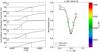 |
Fig. 1 Average formation temperature across a spectral line. Left: normalized cumulative contribution function as a function of temperature at five points across the spectral line shown in the right panel. The dashed line indicates the location of T1/2, i.e., where the contribution function is 50%. Right: line profile of one of the solar lines. The five points for which the contribution function is computed are indicated by large dots color-coded with the T1/2values. |
3.1 Computing the Average Formation Temperature
PySME automatically calculates the temperature profile, T (τ0), on a grid of optical depths, τ, where the zero subscript signifies a reference wavelength of 5000 Å. In order to evaluate other wavelengths, λ, the corresponding optical depth, τλ, is given by (Gray 2005)
 (1)
(1)
where κ is the sum of the line and continuum opacities. The cumulative contribution function, C(τλ), which provides the emergent flux at a certain depth, is proportional to the source function, S (τλ), according to the following integral:
 (2)
(2)
By evaluating the source function, which is also provided by PySME, for a discrete grid in optical depths, the integral in Eq. (2) becomes a summation, and the contribution function can be normalized by dividing with its last point. Finally, because the temperature profile and contribution function are computed on the same grid of optical depths for any given wavelength, a change of variable can be made to obtain the contribution function as a function of temperature. Because we implement a 1D plane-parallel model atmosphere, the optical depth and temperature are equivalent variables in the sense that they both monotonically increase with geometrical depth (although at different rates). However, we chose to convert into temperature as a more intuitive metric that can also easily be related to the commonly known stellar effective temperatures. We refrained from attempting to convert into geometrical depth because this involves the inclusion of wavelength-dependent stellar radii and their uncertainties.
As a diagnostic average formation, we extracted the temperature at which the cumulative contribution function was equal to 50%, denoted Τ1/2, which was obtained through a linear interpolation. Figure 1 shows Τ1/2 computed at five different points across one of the solar lines, demonstrating that points close to the continuum are formed in hotter (deeper) parts of the photosphere, whereas the line core is formed in cooler (shallower) regions. Although Fig. 1 only demonstrates the derived T1/2 value for five line points across a single spectral line, the calculations were repeated for every single observed wavelength point of the HARPS and HARPS-N spectra. The bottom panel of Fig. 2 shows the entire HARPS-N solar spectrum converted into units of Τ1/2 rather than flux. The formation temperature roughly traces the shapes of the spectral lines locally. The global decrease at longer wavelengths is due to the increase in continuum opacity, which in the optical wavelength range is dominated by the bound-free absorption of the negative hydrogen ion (Gray 2005).
3.2 Line Selection
In order to properly asses the average formation temperatures for each spectral point, we considered lines that are well modeled by the spectral synthesis. To identify spectral lines that are unblended and symmetric, we initially used the morphological parametrisation described in Appendix C of Cretignier et al. (2020a). Starting from this line selection, we then considered our two syntheses. For each spectral line, we verified whether the high-resolution profile contains multiple local minima, in which case we rejected the line due to blending. Additionally, we also measured the line-depth weighed χ2 between the instrumental-resolution profile and the observed profile, and rejected all the lines for which the χ2 is more than 4σ larger than the median value, which can occur due to faulty atomic parameters in the VALD3 database. Figure 3 demonstrates the comparison between observed and synthesized solar spectra for an accepted line, a line rejected because of hidden blends, and a line rejected because of a large discrepancy.
For each spectral line in the master spectrum, the CB was computed by fitting a second-order polynomial to the center-most seven points. The CB was derived from the difference between the fitted center and the laboratory wavelengths found from a cross-match with the VALD3 line list.
Figure 4 shows the solar CB versus Τ1/2 interpolated at the line cores; the errors were estimated from the uncertainties of the polynomial coefficients. The figure shows that our selection of unblended lines clearly accentuates the dependence of CB on certain line properties, as well as how the relation is transformed from nonlinear to linear when it is plotted against formation temperature as opposed to the more common line depth (see, e.g., Fig. 3 in Reiners et al. 2016). The CB of α Cen B, shown in Fig. B.1, follows the same relation, although with a smaller slope than for the Sun, which reflects the expected behavior of more extensive convective envelopes and thus smaller convective velocity gradients in stars with a later spectral type (e.g., Meunier et al. 2017b; Liebing et al. 2021). The CB of α Cen B does not reach near-zero values at low temperatures, however, which is likely due to the difficulty of constraining the gravitational redshift and orbital motion of the two main components in the α Centauri system (e.g., Pourbaix et al. 2002).
Although the linearity with temperature appears clearly when we only consider lines for which the estimated core formation temperature is assumed to be reliable, as in previous studies (e.g., Gray 2009; Reiners et al. 2016), we are unable to provide a physical explanation for its origin. To verify the interpretation of the trend, namely that the convective velocity increases linearly with the stellar temperature profile, it might be compared with more complex magnetohydrodynamical (MHD) stellar models that take convection into consideration. Such a model comparison is beyond the scope of this study, and we note that the following analysis is ultimately unaffected by the CB because our RV time series are derived with respect to a master spectrum, for which the absolute shift is of lesser importance. The CB, which provides the shift relative to laboratory measurements, is presented here to validate our line selection and derivation of the average formation temperature. By showing its inverse proportionality with respect to the core formation temperature, which increases with decreasing line depth on average, we are able to demonstrate consistency with the literature.
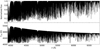 |
Fig. 2 HARPS-N solar spectrum. Top: in units of normalized flux. Bottom: converted into units of average formation temperature. |
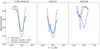 |
Fig. 3 Observed (black) and synthesized (green and blue) spectra shown at the position of three exemplary spectral lines. The synthesis including turbulence and rotational broadening and at the instrumental resolution is shown in green. The synthesis without turbulence and rotational broadening and at the highest resolution for the observational wavelength grid is shown in blue. Left: line considered unblended and included in our study. Middle: line rejected due to a blend seen in the unbroadened synthesis. Right: line rejected due to large discrepancy between the observation and the broadened synthesis. |
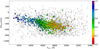 |
Fig. 4 Solar convective blueshift as a function of T1/2 at the line cores. Only lines that could be cross-matched with the VALD3 line list are displayed. The markers of lines from the final selection are color-coded, and the line depth is shown in the color bar. The other lines are shown in gray. The gravitational redshift of RVgrav= GM/Rc, where M and R are the solar mass and radius, has been subtracted. |
3.3 RV Per Temperature Bin for Individual Spectral Lines
After we calculated Τ1/2 for all points of the master spectrum (see Sect. 3.1), our goal was to measure the RV for different bins in average formation temperature as a function of time by measuring it for each individual spectrum from which the master was built. The RV was derived by template matching as described in Dumusque (2018) and Cretignier et al. (2020a), using the master spectrum as the template. We constructed the temperature bins by heuristically dividing the entire range of Τ1/2 values (for the entire spectrum) into Ν intervals of equal length, where Ν is a positive integer. For each line profile, we then measured the RVs of separate segments by identifying which points are formed within the unique temperature bins. We remark that each line was divided into Ν segments at most, but the majority of lines only have points in a subset of bins. Generally, the core will constitute the line segment formed at the coolest temperature bin, whereas hotter temperature bins will have nearly symmetrical contributions from the left and right wings. As an example, if we assume that the line in Fig. 1 is divided into three segments, then points near dot 3 are associated with a low-temperature bin, points near dots 2 and 4 are associated with a medium-temperature bin, and points nears dots 1 and 5 are associated with a high-temperature bin. Line segments with fewer than three points were discarded to have a good estimate of the flux derivative needed to compute the RVs (see Bouchy et al. 2001). The end product is an RV matrix with dimensions Nspec × Nline × Ntemp, where Nspec is the number of spectra in the time series, Nline is the number of spectral lines, and Ntemp is the selected number of temperature bins, for which some of the entries are empty due to a lack of line points. A matrix of equal size was created for the corresponding RV uncertainties. Averaging the RV measurement of all lines for a given temperature bin (see Sect. 3.4) allowed us to reach a high RV precision, and therefore to investigate whether the stellar activity signal dependends on the average formation temperature.
Identifying line segments on the master spectrum and then using those for each individual spectrum might raise concerns about different spectral sampling and Doppler shifts between the spectra. The first problem is not an issue as the master spectrum and the individual spectra are sampled on the same wavelength grid. Although the master spectrum and the individual spectra are all in the same restframe, stellar activity will induce peak-to-peak Doppler shifts of a few dozen meters per second at most for our target stars. These shifts represent less than a tenth of a pixel (~820 m s−1 for HARPS and HARPS-N), and therefore do not hamper the identification of line segments.
Although line profiles in units of average formation temperature closely resemble their flux counterparts, the idea behind using temperature bins rather than flux bins is that the two quantities are inherently different, both locally for single lines and globally for the entire spectrum. If two lines of equal line depths yet unequal atomic properties were compared (such as elemental species, ionization stage, or excitation energies), they would not necessarily be formed at the same temperature, which depends on the line opacity and hence on these individual properties. This is shown in Fig. 5, where the flux profiles of a few lines are color-coded with their Τ1/2 values. The cores of shallow lines are not colored in the same way as the wings of deeper lines at equal flux levels. Likewise, as was shown in Fig. 2, when the entire spectrum is considered, wavelength-dependent variations of the continuum opacity occur as well. Both of these effects motivate the usage of formation temperature as a preferred variable for probing photospheric height and the types of activity occurring at various heights.
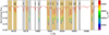 |
Fig. 5 15 Å spectral window color-coded according to the average formation temperature. The shaded areas indicate whether a spectral line is selected (beige) or rejected (gray). The labels above some spectral lines specify the element and ionization of identified lines. |
3.4 RV Per Temperature Bin for the Spectral Line Average
Before averaging line segments from the same formation temperature bin together to increase the RV precision, we curated the selection of line segments included in the averaging. For each RV time series per line and per temperature bin, we removed outliers in the RVs and their uncertainties through an iterative 4σ clipping (the clipping was only upper-ended for the uncertainties, i.e., we only removed points for which the uncertainty was 4 standard deviations larger than the median error bar). RV time series that contained more than 5% outliers were entirely rejected. In addition, time series with a z-score (defined as the RV root mean square (RMS) divided by the median uncertainty) lower than 2 were also excluded before we averaged, to reject time series without significant information. We note that for the four-bin configuration, the 5% outlier criterion rejects an average 5.5% of the RV time series, while the z-score criterion rejects 9.9% of them.
The average RV time series per temperature bin was then obtained by averaging the RVs of all remaining spectral line segments, weighting by their inverse variance at each time point. This results in an RV matrix with dimensions Nspec × Ntemp·
4 Results
4.1 Short-term RVs of the Sun
Short-term RV measurements of the Sun were performed on 105 daily binned spectra taken between June 20 and October 19, 2016, in order to cover a few solar rotational periods during an active-Sun phase. Figure 6 shows the inverse-variance weighted RV time series of all considered lines when the formation temperature was increasingly divided into one to four bins of equal length (see Sect. 3.3), denoted ΔΤ1/2(Ν, n), where Ν is the number of bins and 1 ≤ n ≤ Ν is the bin index. The figure also shows the corresponding normalized generalized Lomb-Scargle (GLS; Zechmeister & Kürster 2009) periodograms for each time series with the 1% false-alarm probability (FAP) indicated. The top left panel of Fig. 6, for the configuration of just one temperature bin (equivalent to no line segmentation based on formation temperature), therefore shows the same RV time series as other traditional methods of measurements would produce, that is, by measuring LBL RVs and averaging over all lines, or by cross-correlating with a spectral type mask. The periodogram in the top right panel also shows two expected peaks at the solar synodic rotation period of ~27 d and half of it (the first harmonic). As the RVs are separated into an increasingly larger number of temperature bins (second, third, and fourth rows in Fig. 6), we note the emergence of a signal in the coolest temperature bin that is anticorrelated with respect to the total signal and has a significantly stronger periodogram peak at half the rotation period.
Table 2 lists the temperature intervals we used for each bin configuration, the number of selected lines (which differs between configurations depending on the sigma-clipping and z-score criteria described above), and the RV RMS for each bin. For the configuration with four bins, the RMS verifies that the coolest and hottest bins, ΔT1/2(4,1) and ΔT1/2(4,4), show a larger dispersion than the intermediate bins. Even though the bin averages are calculated using a varying number of lines (because some bins only exist for a certain subset of lines), the z-score criteria ensures that larger uncertainties are only included when the RMS is upscaled by at least the same amount.
While Fig. 6 provides a visualisation of the collective (or rather, average) behavior of all considered lines over time, it does not inform us about the individual lines that contribute to each bin. Figure A.1 shows a corner plot of various line parameters in which each dot is an individual line. The dots are colored according to the temperature bin to which they belong for the configuration with four bins (same as the bottom panel of Fig. 6). For the distribution of the various line parameters and their covariances, we state the following remarks:
Central wavelength, λc: none of the bins except for the hottest bin (red) depend on chromaticity. The reason is that the gradient of the continuum opacity (see Fig. 2) causes the hottest bin to be biased toward shorter wavelengths.
Line depth, dc: all bins include lines of any line depth, except for the coolest (purple) bin, which primarily consists of the cores of the strongest lines.
Convective blueshift, RVcb : increases (i.e., approaches zero due to its negative nature) gradually with decreasing temperature. The line segments from the coolest bin are the least affected by CB.
RV RMS for the time interval in Fig. 6: similar distributions for all bins. Line segments with the smallest scatter originate from an intermediate (cyan) bin.
Pearson correlation between LBL RV and mean RV (i.e., average total RV without temperature binning, same as the upper panel of Fig. 6), ℛ(RV, 〈RV〉): most line segments are weakly correlated with the average RV, except for those from the coolest bin, which are evenly spread around zero correlation.
Pearson correlation between LBL RV and Ca II H&K S -index, ℛ(RV, S): most line segments are weakly correlated with the S -index, except for those from the coolest bin, which are mostly weakly anti-correlated.
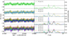 |
Fig. 6 Solar short-term RVs. Left: time series for one to four temperature bins. Each point is the weighted average of all spectral lines with RV values for a given bin. The shaded intervals represent the 16th to 84th percentile of all RVs at any given time point. Times are given in Barycentric Julian Date (BJD). Right: GLS periodograms of the time series shown in the left panels. The legend displays the temperature bin symbol (see main text and Table 2 for the definition). The dashed line indicates the 1% FAP level. |
4.2 Solar Simulations with SOAP–GPU
To enable the comparison between the temperature-binned RVs and the impact of different active regions, we implemented solar simulations for the same time interval as in Sect. 4.1 with the SOAP–GPU code (Zhao & Dumusque, in prep.), a GPU-based successor to the SOAP 2.0 code (Spot Oscillation And Planet, Dumusque et al. 2014). SOAP–GPU simulates RVs by modeling the observed solar disk as a grid of pixels. Each pixel is assigned a line-of-sight velocity from the combined contributions of rotation and CB. The code then injects each pixel with one of two spatially resolved solar spectra, either a quiet-Sun spectrum or a sunspot spectrum, which are Doppler shifted according to the velocity of each pixel. A disk-integrated spectrum is computed by summing all pixels, after scaling the intensity levels with limb darkening and lower or higher contrast for the pixels selected as spot or facula pixels.
From the Helioseismic and Magnetic Imager (HMI) instrument on board the Solar Dynamics Observatory (SDO)3, we retrieved continuum intensitygrams and magnetograms with a cadence of 720 s. We retrieved one frame at noon for every day available between the dates used in Sect. 4.1. We then followed the method in Haywood et al. (2016) to extract a threshold map of spot locations from the flattened intensitygrams and facula locations from the unsigned magnetograms. Spot pixels were identified as those where the intensity is below 89% of the quiet-Sun intensity, and faculae pixels are those where the unsigned magnetic field is stronger than three times its standard deviation. With a clustering algorithm, we searched for pixel clusters in the threshold maps to find the most prominent regions in each set of images. Isolated pixels were rejected due to possible fluctuations. Large faculae are defined as regions covering at least 20 µHem, and the remaining selected pixels were associated with the network that covers almost the entire disk. For each spot and large facula, the spherical coordinates and radius of the corresponding circle with equal area (see Fig. 7) were computed and given as the sole input to SOAP–GPU.
SOAP–GPU enables the total RV signal to be separated into the contributions of different active regions (i.e., spots, faculae or both combined) and effects (i.e., flux, convection, or both combined), shown in Fig. 8. We then linearly interpolated the simulated RVs onto the same time sampling as the observations and cross-correlated the temperature-binned RV time series with the simulated contribution of every combination of region and effect by computing the Pearson correlation coefficient for each configuration while allowing for a phase lag from −14 to 14 days (covering just over one rotational period) in steps of one day (see Fig. 9). The two hottest temperature bins are strongly correlated with the convective effect of faculae, the next-coolest bin is not strongly correlated with any type of contribution, and the coolest bin is ambiguously anticorrelated with faculae flux with a lag of minus one day or faculae convective inhibition with a lag of five days. It is intuitively difficult to argue why stellar activity signals would propagate from one temperature region to the next on a timescale of several days, therefore, it is more likely that the coolest bin in temperature is related to the flux effect induced by faculae.
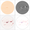 |
Fig. 7 Active regions on the solar surface. Top panels: flattened inten-sitygram (left) and magnetogram (right) of the Sun taken by SDO/HMI on July 17, 2016, at UT12:00:00. Bottom left panel: pixels identified as spots (blue) or faculae (red). Bottom right panel: circles representing the same area for spots (blue) and large faculae (red) as the left panel, used as SOAP–GPU input. |
4.3 Long-term RVs of the Sun
Long-term RV measurements of the Sun were performed on 607 daily binned spectra taken between July 29, 2015, and July 15, 2018, spanning almost three years near the end of solar cycle 24. In order to simultaneously visualize the variability that was observed on the short-term timescale in Sect. 4.1 over several similar intervals and the overall variability when considering the total available time span, we made use of a sliding periodogram, as shown in Fig. 10 for the configuration of four temperature bins. The sliding periodogram primarily consist of a color map in which each column represents the GLS periodogram of a fixed time window (here set to 100 days to equate a few solar rotation periods similar to the short-term interval). The window is slid one day for each column, and windows containing less than 75% of the expected number of data points (i.e., 75 points for our window size of 100 days) are left as blank columns. The color map therefore always has gaps of 25% of the window size on the farthest left and right edges, and its vertical extent (the maximum fitted period) is equal to the window size itself. The upper panel of the periodogram shows the entire RV time series, and its conventional periodogram is displayed in the right panel.
The sliding periodograms indicate that the 100-day windows show a consistent power distribution over approximately the first half of the covered time period, corresponding to the near end of the most recent solar cycle, during which the Sun showed significant levels of activity and active region coverage. In the overall time span, we find the most extreme temperature bins (the coolest and hottest) to be dominated by the long-term magnetic cycle, and they are apparently oppositely affected, similar to their short-term behaviors. The intermediate bins are less affected by low-frequency signals, but still show relatively strong amplitudes at half the solar rotation period.
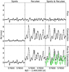 |
Fig. 8 SOAP–GPU generated RVs for the same time points as in Fig. 6, separated into active regions (spots, faculae, and both) and effects (flux, convection, and both). The green curve in the lower right panel is the observed RVs without temperature binning. |
4.4 RVs of α Cen B
RV measurements of α Cen B were performed on the 2010 observations, which have been studied extensively (see, e.g., Dumusque 2018; Cretignier et al. 2020a). The RV curation of α Cen Β followed the same steps as for the Sun, and the results are shown in Appendix B.
We find a similar behavior for the temperature-binned RVs; the coolest bin is even more strongly anticorrelated with the S -index. The main difference for α Cen B, however, is the lack of power in the periodograms at about half the rotation period. This could be explained by the stellar inclination of α Cen B, which is thought to be  (Dumusque 2014), which weakens the impact of the flux effect due to a decreased rotational velocity component along the line of sight. This inclination also causes active regions near the northern pole to remain visible during the entire rotation, which amplifies the signal at the rotation period, and not at half the period, like for the equator-on Sun.
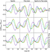 |
Fig. 9 Pearson correlation between observed and simulated RVs as a function of time lag. The four temperature bins are represented by the same colors as in Fig. 6. |
5 Discussion
The analysis performed in this paper implies that the activity-induced temporal RV signal is dependent on the formation temperature inside the stellar photosphere. We demonstrated that the measured time series differs in amplitude and periodicity when it is computed on line segments formed at various temperature ranges. From solar simulations on short timescales, we find that convection and its inhibition inside active regions due to strong magnetic fields is responsible for most of the observed effect. This dominant contribution is primarily measured in line segments formed at higher temperature ranges, that is, deeper parts of the photosphere where convective velocities are expected to be higher and their suppression more noticeable. However, for the lower-temperature ranges (high in the photosphere), we detect an effect that does not seem to be explained by convection and is likely due to a change of the physical conditions. Some indicators show that the signal in this cooler temperature range might stem from the flux effect of active regions (due to its stronger periodogram power at half the solar rotation period). Although this is not satisfactory supported by the simulated RV flux contributions without considering unexplained lags, we do not rule out that the simulated RV curves might not fully capture line shape variations that affect line segments formed at some temperatures more than other. The explanation by some other unaccounted-for physics driving the behavior is beyond the scope of this paper, but we point out a possible change in the contrast of either the active regions or the quiet-Sun granular pattern (e.g., Janssen & Cauzzi 2006; Cheung et al. 2007).
With the average formation temperature as a diagnostic tool, foreseeable improvements could still be made in its derivation for certain spectral portions. For example, the inclusion of non-LTE departure in the syntheses might enable us to model the strongest lines more accurately, whose line cores are the primary constituents of the coolest temperature ranges. By improving their synthesis and thus also their formation height, their primary source of variability might be more easily distinguished and the physical processes behind the source might be better understood.
We also note that in Sect. 4.2, although we compared the temperature-binned RVs to the SOAP–GPU simulations, it is not straightforward to which extent the comparison is valid when only segments of lines are considered. Even if SOAP–GPU were able to fully model the physics, the simulated velocities would always be averaging over all formation temperatures. Our assumption is that the isolated contributions still affect the entire lines in the same way as they would on the line segments in which they are most pronounced, although to a lesser extent when combined with the less sensitive segments. Although the magnitudes of the effects cannot be compared, the shapes and phases should therefore be comparable.
It is evident from the existing literature that the interplay between magnetic fields and multiscale convective motion indeed currently prevents RV precision from reaching the sub-m s−1 level. Although a careful selection of lines results in a higher RV precision for some temperature bins, it remains to be determined which partition strategy is the best. The trade-off between the number of bins and the number of lines per bin is so far arbitrary and should perhaps be physically motivated by stellar structure models and the instrumental noise level rather than by the circumstantial range of temperatures from the sample. In a future paper, we intend to explore this parameter space further, for instance, by investigating for which temperature interval a minimum dispersion is attained, and at which break-off temperature the strongest periodogram peak transitions between the fundamental and harmonic periodicities. We will also consider developing a mitigation technique in which a linear combination or gradient of the total RV measured in various temperature ranges can be used to distinguish the activity signals from a planet-induced pure Doppler signal, which should be of equal magnitude and be invariant between temperature bins.
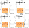 |
Fig. 10 Sliding periodogram of the temperature-binned RV time series of the Sun. Upper panels: total RV time series with the short-term interval used in Sect. 4.1 indicated by the gray shaded area. Right panels: GLS periodogram of the total time series, with the solar rotation period and its first harmonic indicated by the dashed lines. The columns of the central color maps show the GLS periodogram of every 100-day window, where darker colors indicate stronger power. The window is shifted in steps of one day, and gaps correspond to windows in which more than 25% of the data points are missing. |
6 Conclusions
We built further upon the technique of measuring RVs of individual spectral lines. By employing LTE spectral synthesis, we were able to estimate the average formation temperature of spectral line points as sampled by the HARPS-N and HARPS high-resolution spectrographs for the Sun and α Cen B, respectively.
With a careful selection of unblended symmetric lines and with the average formation temperate as a diagnostic tool, we investigated how various activity-related properties depend on the formation temperature. Our primary reasoning was that formation temperature is mapped more consistently with photospheric depth than with line depth, and should be a more suitable variable for probing different layers. We began by showing that the absolute convective blueshift of line cores becomes a linear function of formation temperature, instead of a nonlinear function of line depth. This is observed for the two target stars we studied.
We were furthermore able to demonstrate that spectral line segments that formed at different temperatures in the photosphere can be used to diagnose the impact of stellar activity on the measured RVs at both rotational (see Figs. 6 and B.2) and magnetic cycle timescales (see Fig. 10). Comparison with RV simulations covering a few rotations during which the Sun experienced heightened levels of active region coverage indicates that convection and its inhibition due to magnetic fields is the dominant effect and perturbs spectral parts that formed deeper in the photosphere (at higher temperatures). For both short and long timescales, the line segments that formed at cooler temperature ranges exhibit an inverted RV variation than the hotter temperature ranges. Measuring the RV for different temperatures in the photosphere could therefore be a powerful tool to differentiate between stellar activity signals and a planetary signal. It remains to be investigated whether different types of stellar activity can be entirely disentangled through partitioning of formation temperature as a proxy for photospheric depth, and if variations in RV with temperature can be used to mitigate the activity patterns and enhance potential planetary signals.
Acknowledgments
We thank the referee for useful comments which helped improve the clarity of the manuscript. We thank Lucia Kleint for interesting discussions. This work has been carried out within the framework of the NCCR PlanetS supported by the Swiss National Science Foundation. This project has received funding from the European Research Council (ERC) under the European Union’s Horizon 2020 research and innovation program (grant agreement SCORE No. 851555). This work has made use of the VALD database, operated at Uppsala University, the Institute of Astronomy RAS in Moscow, and the University of Vienna. This work has made use of the HARPS-N solar RVs as well as ESO public HARPS data.
Appendix A Corner plot for the Sun
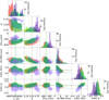 |
Fig. A.1 Corner plot of various line parameters of the Sun for four temperature bins. From left to right, we show the central wavelength, line depth, convective blueshift, the correlation between LBL RV and mean RV, and the correlation between LBL RV and S index. The dashed lines and contours indicate the medians and the ±1σ kernel densities, respectively. The color-coding is the same as in Fig. 6. |
Appendix B Figures and tables for α Cen Β
References
- Arentoft, T., Kjeldsen, H., Bedding, T. R., et al. 2008, ApJ, 687, 1180 [NASA ADS] [CrossRef] [Google Scholar]
- Bauer, F. F., Reiners, A., Beeck, B., et al. 2018, A&A, 610, A52 [NASA ADS] [CrossRef] [EDP Sciences] [Google Scholar]
- Bouchy, F., Pepe, F., & Queloz, D. 2001, A&A, 374, 733 [NASA ADS] [CrossRef] [EDP Sciences] [Google Scholar]
- Cheung, M. C. M., Schüssler, M., & Moreno-Insertis, F. 2007, A&A, 461, 1163 [NASA ADS] [CrossRef] [EDP Sciences] [Google Scholar]
- Cretignier, M., Dumusque, X., Allart, R., et al. 2020a, A&A, 633, A76 [NASA ADS] [CrossRef] [EDP Sciences] [Google Scholar]
- Cretignier, M., Francfort, J., Dumusque, X., et al. 2020b, A&A, 640, A42 [NASA ADS] [CrossRef] [EDP Sciences] [Google Scholar]
- Cretignier, M., Dumusque, X., Hara, N. C., et al. 2021, A&A, 653, A43 [NASA ADS] [CrossRef] [EDP Sciences] [Google Scholar]
- Dumusque, X. 2014, ApJ, 796, 133 [NASA ADS] [CrossRef] [Google Scholar]
- Dumusque, X. 2018, A&A, 620, A47 [NASA ADS] [CrossRef] [EDP Sciences] [Google Scholar]
- Dumusque, X., Udry, S., Lovis, C., et al. 2011, A&A, 525, A140 [NASA ADS] [CrossRef] [EDP Sciences] [Google Scholar]
- Dumusque, X., Boisse, I., & Santos, N. C. 2014, ApJ, 796, 132 [NASA ADS] [CrossRef] [Google Scholar]
- Gray, D. F. 2005, The Observation and Analysis of Stellar Photospheres, 3rd edn. (Cambridge: Cambridge University Press) [Google Scholar]
- Gray, D. F. 2009, ApJ, 697, 1032 [Google Scholar]
- Gustafsson, B., Edvardsson, B., Eriksson, K., et al. 2008, A&A, 486, 951 [NASA ADS] [CrossRef] [EDP Sciences] [Google Scholar]
- Haywood, R. D., Collier Cameron, A., Unruh, Y. C., et al. 2016, MNRAS, 457, 3637 [Google Scholar]
- Janssen, K., & Cauzzi, G. 2006, A&A, 450, 365 [NASA ADS] [CrossRef] [EDP Sciences] [Google Scholar]
- Kjeldsen, H., & Bedding, T. R. 1995, A&A, 293, 87 [NASA ADS] [Google Scholar]
- Kupka, F. G., Ryabchikova, T. A., Piskunov, N. E., et al. 2000, Balt. Astron., 9, 590 [NASA ADS] [Google Scholar]
- Liebing, F., Jeffers, S. V., Reiners, A., et al. 2021, A&A, 654, A168 [NASA ADS] [CrossRef] [EDP Sciences] [Google Scholar]
- Meunier, N., Desort, M., & Lagrange, A.-M. 2010, A&A, 512, A39 [NASA ADS] [CrossRef] [EDP Sciences] [Google Scholar]
- Meunier, N., Lagrange, A.-M., & Borgniet, S. 2017a, A&A, 607, A6 [NASA ADS] [CrossRef] [EDP Sciences] [Google Scholar]
- Meunier, N., Lagrange, A.-M., Mbemba Kabuiku, L., et al. 2017b, A&A, 597, A52 [NASA ADS] [CrossRef] [EDP Sciences] [Google Scholar]
- Morel, T. 2018, A&A, 615, A172 [NASA ADS] [CrossRef] [EDP Sciences] [Google Scholar]
- Nordlund, Å., Stein, R. F., & Asplund, M. 2009, Liv. Rev. Sol. Phys., 6, 2 [Google Scholar]
- Piskunov, N., & Valenti, J. A. 2017, A&A, 597, A16 [NASA ADS] [CrossRef] [EDP Sciences] [Google Scholar]
- Piskunov, N. E., Kupka, F., Ryabchikova, T. A., et al. 1995, A&AS, 112, 525 [NASA ADS] [Google Scholar]
- Pourbaix, D., Nidever, D., McCarthy, C., et al. 2002, A&A, 386, 280 [NASA ADS] [CrossRef] [EDP Sciences] [Google Scholar]
- Reiners, A., Mrotzek, N., Lemke, U., et al. 2016, A&A, 587, A65 [NASA ADS] [CrossRef] [EDP Sciences] [Google Scholar]
- Ryabchikova, T., Piskunov, N., Kurucz, R. L., et al. 2015, Phys. Scr., 90, 054005 [Google Scholar]
- Schrijver, C. J., & Zwaan, C. 2000, Solar and Stellar Magnetic Activity (Cambridge: Cambridge University Press) [Google Scholar]
- Valenti, J. A., & Fischer, D. A. 2005, ApJS, 159, 141 [Google Scholar]
- Valenti, J. A., & Piskunov, N. 1996, A&AS, 118, 595 [NASA ADS] [CrossRef] [EDP Sciences] [Google Scholar]
- Zechmeister, M., & Kürster, M. 2009, A&A, 496, 577 [CrossRef] [EDP Sciences] [Google Scholar]
- Zhao, L. L., Fischer, D. A., Ford, E. B., et al. 2022, AJ, 163, 171 [NASA ADS] [CrossRef] [Google Scholar]
VALD stands for Vienna Atomic Line Database.
Available at https://github.com/AWehrhahn/SME
Available at https://sdo.gsfc.nasa.gov
All Tables
All Figures
|
Fig. 1 Average formation temperature across a spectral line. Left: normalized cumulative contribution function as a function of temperature at five points across the spectral line shown in the right panel. The dashed line indicates the location of T1/2, i.e., where the contribution function is 50%. Right: line profile of one of the solar lines. The five points for which the contribution function is computed are indicated by large dots color-coded with the T1/2values. |
| In the text | |
|
Fig. 2 HARPS-N solar spectrum. Top: in units of normalized flux. Bottom: converted into units of average formation temperature. |
| In the text | |
|
Fig. 3 Observed (black) and synthesized (green and blue) spectra shown at the position of three exemplary spectral lines. The synthesis including turbulence and rotational broadening and at the instrumental resolution is shown in green. The synthesis without turbulence and rotational broadening and at the highest resolution for the observational wavelength grid is shown in blue. Left: line considered unblended and included in our study. Middle: line rejected due to a blend seen in the unbroadened synthesis. Right: line rejected due to large discrepancy between the observation and the broadened synthesis. |
| In the text | |
|
Fig. 4 Solar convective blueshift as a function of T1/2 at the line cores. Only lines that could be cross-matched with the VALD3 line list are displayed. The markers of lines from the final selection are color-coded, and the line depth is shown in the color bar. The other lines are shown in gray. The gravitational redshift of RVgrav= GM/Rc, where M and R are the solar mass and radius, has been subtracted. |
| In the text | |
|
Fig. 5 15 Å spectral window color-coded according to the average formation temperature. The shaded areas indicate whether a spectral line is selected (beige) or rejected (gray). The labels above some spectral lines specify the element and ionization of identified lines. |
| In the text | |
|
Fig. 6 Solar short-term RVs. Left: time series for one to four temperature bins. Each point is the weighted average of all spectral lines with RV values for a given bin. The shaded intervals represent the 16th to 84th percentile of all RVs at any given time point. Times are given in Barycentric Julian Date (BJD). Right: GLS periodograms of the time series shown in the left panels. The legend displays the temperature bin symbol (see main text and Table 2 for the definition). The dashed line indicates the 1% FAP level. |
| In the text | |
|
Fig. 7 Active regions on the solar surface. Top panels: flattened inten-sitygram (left) and magnetogram (right) of the Sun taken by SDO/HMI on July 17, 2016, at UT12:00:00. Bottom left panel: pixels identified as spots (blue) or faculae (red). Bottom right panel: circles representing the same area for spots (blue) and large faculae (red) as the left panel, used as SOAP–GPU input. |
| In the text | |
|
Fig. 8 SOAP–GPU generated RVs for the same time points as in Fig. 6, separated into active regions (spots, faculae, and both) and effects (flux, convection, and both). The green curve in the lower right panel is the observed RVs without temperature binning. |
| In the text | |
|
Fig. 9 Pearson correlation between observed and simulated RVs as a function of time lag. The four temperature bins are represented by the same colors as in Fig. 6. |
| In the text | |
|
Fig. 10 Sliding periodogram of the temperature-binned RV time series of the Sun. Upper panels: total RV time series with the short-term interval used in Sect. 4.1 indicated by the gray shaded area. Right panels: GLS periodogram of the total time series, with the solar rotation period and its first harmonic indicated by the dashed lines. The columns of the central color maps show the GLS periodogram of every 100-day window, where darker colors indicate stronger power. The window is shifted in steps of one day, and gaps correspond to windows in which more than 25% of the data points are missing. |
| In the text | |
|
Fig. A.1 Corner plot of various line parameters of the Sun for four temperature bins. From left to right, we show the central wavelength, line depth, convective blueshift, the correlation between LBL RV and mean RV, and the correlation between LBL RV and S index. The dashed lines and contours indicate the medians and the ±1σ kernel densities, respectively. The color-coding is the same as in Fig. 6. |
| In the text | |
 |
Fig. B.1 Same as Fig. 4, but for α Cen B. |
| In the text | |
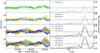 |
Fig. B.2 Same as Fig. 6, but for α Cen B. |
| In the text | |
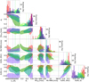 |
Fig. B.3 Same as Fig. A.1, but for α Cen B. |
| In the text | |
Current usage metrics show cumulative count of Article Views (full-text article views including HTML views, PDF and ePub downloads, according to the available data) and Abstracts Views on Vision4Press platform.
Data correspond to usage on the plateform after 2015. The current usage metrics is available 48-96 hours after online publication and is updated daily on week days.
Initial download of the metrics may take a while.