| Issue |
A&A
Volume 537, January 2012
|
|
|---|---|---|
| Article Number | A64 | |
| Number of page(s) | 14 | |
| Section | Cosmology (including clusters of galaxies) | |
| DOI | https://doi.org/10.1051/0004-6361/201117482 | |
| Published online | 10 January 2012 | |
Intracluster light in clusters of galaxies at redshifts 0.4 < z < 0.8⋆
1 LAM, OAMP, Pôle de l’Étoile Site de Château-Gombert, 38 rue Frédéric Joliot-Curie, 13388 Marseille Cedex 13 France
e-mail: This email address is being protected from spambots. You need JavaScript enabled to view it.
2 Núcleo de Astrofísica Teórica, Universidade Cruzeiro do Sul, R. Galvão Bueno 868, 01506–000 São Paulo, SP, Brazil
3 UPMC Université Paris 06, UMR 7095, Institut d’Astrophysique de Paris, 75014 Paris, France
4 CNRS, UMR 7095, Institut d’Astrophysique de Paris, 75014 Paris, France
5 Department Physics & Astronomy, Northwestern University, Evanston, IL 60208-2900, USA
6 Fermi National Accelerator Laboratory, PO Box 500, Batavia, IL 60510, USA
7 OCA, Cassiopée, Boulevard de l’Observatoire, BP 4229, 06304 Nice Cedex 4, France
8 INAF/Osservatorio Astronomico di Trieste, via G.B. Tiepolo 11, 34143 Trieste, Italy
9 Department of Physics and Astronomy, Ohio University, 251B Clippinger Lab, Athens, OH 45701, USA
10 Osservatorio Astrofisico di Arcetri, Largo Enrico Fermi 5, 50125 Firenze, Italy
11 Steward Observatory, University of Arizona, 933 N. Cherry Ave. Tucson, AZ 85721, USA
12 Department of Astronomy and Astrophysics, The University of Chicago, 5640 South Ellis Avenue, Chicago, IL 60615, USA
13 Leiden Observatory, Leiden University, Niels Bohrweg 2, 2333 CA Leiden, The Netherlands
14 Kavli Institute for Particle Astrophysics and Cosmology, Stanford University, 2575 Sand Hill Road, Menlo Park, CA 94025, USA
15 Observatorio do Valongo, UFRJ, Ladeira do Pedro Antonio 43, Saude, Rio de Janeiro 20080-090, Rio de Janeiro, Brazil
16 Dept. of Physics and Astronomy, University of Kansas, Lawrence, KS 66045, USA
17 Kavli Institute for Particle Astrophysics and Cosmology, Stanford University, 382 via Pueblo Mall, Stanford, CA 94305-4060, USA
Received: 15 June 2011
Accepted: 18 September 2011
Abstract
Context. The study of intracluster light (ICL) can help us to understand the mechanisms taking place in galaxy clusters, and to place constraints on the cluster formation history and physical properties. However, owing to the intrinsic faintness of ICL emission, most searches and detailed studies of ICL have been limited to redshifts z < 0.4.
Aims. To help us extend our knowledge of ICL properties to higher redshifts and study the evolution of ICL with redshift, we search for ICL in a subsample of ten clusters detected by the ESO Distant Cluster Survey (EDisCS), at redshifts 0.4 < z < 0.8, that are also part of our DAFT/FADA Survey.
Methods. We analyze the ICL by applying the OV WAV package, a wavelet-based technique, to deep HST ACS images in the F814W filter and to V-band VLT/FORS2 images of three clusters. Detection levels are assessed as a function of the diffuse light source surface brightness using simulations.
Results. In the F814W filter images, we detect diffuse light sources in all the clusters, with typical sizes of a few tens of kpc (assuming that they are at the cluster redshifts). The ICL detected by stacking the ten F814W images shows an 8σ detection in the source center extending over a ~50 × 50 kpc2 area, with a total absolute magnitude of −21.6 in the F814W filter, equivalent to about two L∗ galaxies per cluster. We find a weak correlation between the total F814W absolute magnitude of the ICL and the cluster velocity dispersion and mass. There is no apparent correlation between the cluster mass-to-light ratio (M/L) and the amount of ICL, and no evidence of any preferential orientation in the ICL source distribution. We find no strong variation in the amount of ICL between z = 0 and z = 0.8. In addition, we find wavelet-detected compact objects (WDCOs) in the three clusters for which data in two bands are available; these objects are probably very faint compact galaxies that in some cases are members of the respective clusters and comparable to the faint dwarf galaxies of the Local Group.
Conclusions. We show that the ICL is prevalent in clusters at least up to redshift z = 0.8. In the future, we propose to detect the ICL at even higher redshifts, to determine wether there is a particular stage of cluster evolution where it was stripped from galaxies and spread into the intracluster medium.
Key words: galaxies: clusters: intracluster medium / galaxies: clusters: general
Based on observations made at ESO Telescopes at the Paranal Observatory under programme ID 082.A-0374. Also based on the use of the NASA/IPAC Extragalactic Database (NED) which is operated by the Jet Propulsion Laboratory, California Institute of Technology, under contract with the National Aeronautics and Space Administration. Based on observations made with the NASA/ESA Hubble Space Telescope, obtained from the data archives at the Space Telescope European Coordinating Facility and the Space Telescope Science Institute, which is operated by the Association of Universities for Research in Astronomy, Inc., under NASA contract NAS 5-26555.
Alfred P. Sloan Fellow.
© ESO, 2012
1. Introduction
The search for intracluster light (hereafter ICL) provides a complementary way of determining the mechanisms occurring inside galaxy clusters, as well as constraining the properties and formation history of the ICL. These studies promise to yield possible answers to many fundamental questions about the formation and evolution of galaxy clusters and their constituent galaxies. In addition, it is important to determine how and when the ICL formed, and the connection between the ICL and the central brightest cluster galaxy (see e.g. González et al. 2005). Cosmological N-body and hydrodynamical simulations are beginning to predict the kinematics and origin of the ICL (see e.g. Dolag et al. 2010). The ICL traces the evolution of baryonic substructures in dense environments and can thus be used to constrain some aspects of cosmological simulations that are uncertain, such as the modeling of star formation and the mass distribution of the baryonic light-emitting component in galaxies. Da Rocha et al. (2005) clearly illustrated the significant presence of the ICL in groups, a result that is crucial if we assume that groups are the basic building blocks of clusters and able to bring their own ICL to the cluster-building process.
From a technical point-of-view, modern CCD cameras now allow us to study the properties of the diffuse light in clusters, i.e. its morphology, radial distribution, and colors, in a quantitative way (e.g. Uson et al. 1991; Bernstein et al. 1995; Gregg & West 1998; Mihos et al. 2005; Zibetti et al. 2005; González et al. 2007; Krick & Bernstein 2007; Rudick et al. 2010). However, accurate photometric measurements of the diffuse light are difficult to perform because its surface brightness is typically fainter than 1% of that of the night sky, and it can be difficult (especially at high redshift) to distinguish the extended outer halos of the brightest cluster galaxies (BCGs) in a cluster core from the stars floating freely in the cluster potential, i.e. the intracluster light component. Moreover, the dimming factor plays an important role in our study and makes it intrinsically difficult to detect ICL at high redshift. This cosmological surface-brightness dimming, which follows a (1 + z)4 law, places de facto an upper limit on the redshift to which the ICL can be practically studied, which depends on the image depth and the detection methods.
This explains why, until now, most studies of the ICL have been performed on galaxy clusters at redshifts below z ~ 0.3 (see e.g. Toledo et al. 2011). However, since it is crucial to understand how the evolution of galaxy clusters affects that of the ICL, we must study the ICL within a range of clusters at various redshifts. It would be ideal to investigate as comprehensively as possible the period between z = 0.3 and z ~ 2, and investigate clusters since their birth. We propose here to fill part of this gap in the 0.4 − 0.8 redshift range for a sample of ten clusters. This redshift range is sufficient to cover about half of the typical cluster lifetimes. To help us follow the cluster formation history, we also compare our ICL results in terms of the cluster orientations obtained here with those obtained with the Serna & Gerbal (1996) dynamical method.
Colors are useful for determining the evolution of galaxy clusters, and we were able to detect the ICL in two bands (the HST/ACS F814W-band and the ground-based VLT/FORS2 V-band) for the three lowest redshift clusters. In summary, we studied the diffuse light in ten different clusters in one band up to z ~ 0.8 based on deep HST ACS images and in three of them (up to z ~ 0.58) in two bands with FORS2 data. However, these deep data would have been insufficient if we were not using a very sensitive wavelet-detection technique, the ov_wav method (Pereira 2003; and Da Rocha et al. 2005), itself a variant of the à trous wavelet transform described by Starck et al. (1998; see also Starck et al. 2002). This method is independent of both the galaxy and star modeling, and of the sky level subtraction.
In Sect. 2, we describe the sample and observational data. In Sect. 3, we present the data analysis methods and detection efficiency estimates. In Sect. 4, we present our analysis for the F814W images. In Sect. 5, we discuss the nature of our detections, taking advantage of our V-band data. Finally, our main results are summarized in Sect. 6. Throughout the paper, we assume that H0 = 71 km s-1 Mpc-1, Ωm = 0.27, and ΩΛ = 0.73. All magnitudes are in the AB system.
2. Sample and observational data
2.1. The cluster sample
Our study is focused on ten clusters from the Las Campanas Distant Cluster Survey (hereafter LCDCS: González et al. 2001) observed in the HST/ACS F814W-band, and for three of these ten clusters also in the VLT/FORS2 V-band. The LCDCS sample consists of optically selected clusters in the z = [0.3, 1] range identified from fluctuations in the extragalactic background light. The LCDCS was a drift-scan imaging survey of a 130 deg2 strip of the southern sky. Selection criteria for the LCDCS survey were fully automated so it constitutes a well-defined homogeneous sample that can be used to address issues of cluster evolution and cosmology. Several studies have already been performed for these individual clusters (e.g. Halliday et al. 2004; and Milvang-Jensen et al. 2008).
The ten considered clusters are also part of the DAFT/FADA Survey, which consists of 91 distant clusters ranging from z = 0.4 to z = 0.9 and for which we have images in several bands 1.
These ten clusters were chosen because of the very deep HST/ACS F814W data available (prop. 9476, PI: J. Dalcanton), especially in a central ~2 × 2 arcmin2 area (see next section). We present in Table 1 the basic characteristics of these ten clusters, including the redshift, velocity dispersion, and mass-to-light ratio (M/L) from Clowe et al. (2006), and the total ICL F814W absolute magnitude.
Main characteristics of the ten clusters observed, and total ICL F814W absolute magnitudes.
2.2. Observational data
2.2.1. HST ACS data
We have at our disposal HST ACS F814W data, each image including four tiles (2 × 2 mosaic) of 2 ks and a central tile of 8 ks (Desai et al. 2007). The depth achieved for point sources at the 90% level is on the order of 28 mag for the deep parts and 26 mag for the shallow parts in F814W (see Guennou et al. 2010). These values are only estimates of the true completeness levels as the simulated objects do not perfectly reproduce the full range of real object profiles. In addition to the different exposure times, the different thresholds used in SExtractor for the shallow and deep regions also explain the two magnitude difference between the two completeness levels2. The full data reduction technique is described in Schrabback et al. (2010) but here we describe the salient points. The data were reduced using a modified version of the HAGGLeS pipeline, with careful background subtraction, improved bad pixel masking, and a proper image registration. Stacking and cosmic ray rejection were done with Multidrizzle (Koekemoer et al. 2002), taking the time-dependent field-distortion model from Anderson (2007) into account. The pixel scale was 0.05 arcsec and we used a Lanczos3 kernel. After aligning the exposures of each tile separately, we determined the shifts and rotations between the tiles from separate stacks by measuring the positions of objects in the overlap regions. As a final step, we created mosaic stacks by including all tiles for a given cluster.
2.2.2. FORS2 V-band data
FORS2 is a multi-mode (including an imaging-mode) optical instrument mounted on the ESO VLT/UT1 Cassegrain focus. The considered images had 0.25 arcsec pixels, covering a 6.8 × 6.8 arcmin2 field of view. Guennou et al. (2010) showed that the V-band images we selected were basically complete down to F814W ~ 26 for point sources. We refer the reader to White et al. (2005) for further details about the observations.
3. Methods
3.1. Wavelet analysis
Deep images are not always sufficient to detect ICL in distant clusters because of the dimming factor. We therefore applied the very sensitive detection ov_wav package (see e.g. Pereira 2003; and Da Rocha & Mendes de Oliveira 2005) to our HST F814W images and FORS2 V-band images. The method is a multi-scale vision model (e.g. Rué & Bijaoui 1997), and we now describe its main steps. After applying the wavelet transform (i.e. the à trous algorithm) to a given “sky image” (direct observation of the targeted cluster), a thresholding in the wavelet transform space is performed to identify the statistically significant pixels. These are grouped in connected fields by a scale by scale segmentation procedure, to define the object structures. An inter-scale connectivity tree is then established and the object identification procedure extracts each connected tree that contains connected fields of significant pixels across three or more scales and, by referring to the object definition, can be associated with the objects. Finally, an individual image can be recovered for each identified object, by applying an iterative reconstruction algorithm to the data contained in the corresponding tree. Both measurement and classification operations can then be carried out.
Since the images were by far too wide (8k × 8k) for the code to operate efficiently, we divided the total area to be analyzed into five subareas (see below).
In a first step, we detected high frequency objects in a two pass process. These objects were first detected in the sky image to produce our first object image. We used characteristic scales between 1 and 1024 pixels in the wavelet space. The first object image was then subtracted from the sky image to produce the first residual image. This first residual image therefore still includes objects larger than 1024 pixels (51.2 arcsec diameter), as well as several smaller previously hidden features. These hidden features are typically objects too faint to satisfy the wavelet first-pass thresholding conditions described in the following. We then detected objects in this residual image, on characteristic scales of between 1 and 128 pixels, to create a second object image still including objects larger than 128 pixels (6.4 arcsec diameter), as well as again several smaller previously hidden features. This second object image was then subtracted from the original sky image to produce a second residual image. The main parameter for the object detection in the wavelet method was a significance level of at least 5σ for each of the two passes.
At this point, most of the major compact objects were removed from the second residual image. Small-scale (radius smaller than 3.2 arcsec) bright diffuse-light sources also have been removed. At z ~ 0.6, this means that plume-like structures (see e.g. Gregg & West 1998) of smaller than ~40 kpc have been removed from the second residual image. In a similar way as in Adami et al. (2005), the third pass involves a search for what we call the real ICL sources, i.e. the most extended surface-brightness features in the second residual images. These features were detected by considering pixels where the signal was larger than 2.5σ (for each of the clusters), compared to an empty area of the residual image. Each of these sources was visually inspected before the removal of obvious residuals of bright saturated Galactic stars or defects due to image cosmetics (for example, areas of low signal-to-noise ratio). By definition, ICL sources do not include star residuals.
We show in Fig. 1 our results for the central area of LCDCS 0541. Objects detected in the first two passes are all compact and similar to either classical galaxies or stars. Also, a large part of them are detected by a SExtractor analysis, with the exception of several very faint objects that we later discuss and refer to as “wavelet-detected compact objects” (hereafter WDCOs). These WDCOs are wavelet-detected (during the two first passes) objects that would not have been detected by SExtractor.
Objects detected in the third pass are several tens of kpc wide; they are not compact objects such as galaxies, but are what we refer to as real ICL sources.
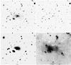 |
Fig. 1 1.1 × 1.1 arcmin2 images of the various steps of the wavelet analysis for LCDCS 0541. Upper left: sky image; upper right: first pass objects; lower left: second pass objects; lower right: final residual image. |
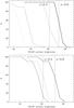 |
Fig. 2 Upper panel: percentage of recovered diffuse light sources in HST ACS images. Curves to the right are related to the wavelet detections. Curves to the left are relative to the SExtractor detections. Dotted curves are relative to shallow HST ACS image areas. Continuous curves are relative to deep HST ACS image areas. The two vertical lines show the brightest Coma cluster known diffuse light source (a ~ 60 kpc wide source) redshifted to z = 0.4 and z = 0.8. Lower panel: percentage of recovered diffuse light sources in FORS2 V-band images. The two vertical lines show the brightest known Coma cluster diffuse light source redshifted to z = 0.4 and z = 0.8. All curves correspond to the wavelet detection. The continuous curve represents very blue objects (V − F814W = 1), the dotted curve blue objects (V − F814W = 2.1), and the dashed curve red objects (V − F814W = 2.6). |
3.2. Detection efficiency
Before attempting any analysis of our detections, a crucial step is to assess the detection levels of our method as a function of the surface brightness of the diffuse-light sources. No diffuse light source catalog is available for the considered cluster sample, so we rely entirely on simulations to assess our ability to detect these sources. To achieve this, we employed a classical method where artificial sources are introduced into real images and then detected with our codes. The same method was applied for example in Adami et al. (2006) to estimate the detection levels of low surface brightness galaxies in the Coma cluster. Since both HST ACS and FORS2 V-band exposure times and observing conditions were similar for all the considered clusters (see e.g. Guennou et al. 2010), we arbitrarily selected the LCDCS 0541 cluster F814W and V images to perform our tests.
As a model of diffuse light sources, we chose a uniform disk with a radius of 25 pixels that we scaled to different surface brightnesses. These 25 pixels correspond to a ~20 kpc wide object at z ~ 0.8, which is typical of major-galaxy sizes. It is of intermediate size between the WDCOs and the real ICL sources. The predicted detection levels will therefore be intermediate between the WDCOs and the true detection rates of the ICL sources. Surface brightnesses were chosen in successive 0.5 mag wide bins between F814W = 21.5 and 28.5 mag/arcsec2. We used various V − F814W colors to include these objects in the V-band images, namely V − F814W = 1, 2.1, and 2.6. These values are typical of very blue, blue, and red objects (see Fig. 2).
For each magnitude bin, we repeated the exercise ten times to compute a mean detection rate. We were unable to repeat this 100 times as in Adami et al. (2006) because the wavelet detection algorithm would have required a prohibitively long computing time. The whole process was performed in various places in both the deep (10 ks) and the wide (2 ks) HST ACS image areas. In Fig. 2, we display our results and compare them with the detection levels achieved using a classical SExtractor detection (Bertin & Arnouts 1996, with a 1.8σ detection threshold and a minimum significant area of 4 pixels) instead of the wavelet technique.
We clearly see that SExtractor detections are basically impossible for objects fainter than F814W ~ 24 mag/arcsec2, even when considering the deepest parts of the HST ACS images. The use of the wavelet technique allows a magnitude gain of at least 3.5 (at a cost of a factor of nearly 1000 in computing time).
We roughly estimated whether these detection levels are sufficient to detect typical diffuse light sources redshifted to the considered cluster distances. We selected the brightest diffuse light source detected in Coma (source 3 of Adami et al. 2005) and estimated its F814W surface brightness by using the colors given in Fukugita et al. (1995) and applying (1 + z)4 cosmological dimming. This source is very similar to the ICL sources listed in Table 1, with a diameter of ~60 kpc, no significantly peaked surface brightness profile, and a mean surface brightness of RVega ~ 25 at z = 0.023. The deduced F814W surface brightnesses at z = 0.4 and z = 0.8 (extreme redshift values of our cluster sample) are shown in Fig. 2 as the two vertical lines. However, we must keep in mind that these vertical lines are valid for very extended ICL sources, while the detection levels shown in Fig. 2 are for smaller (25 arcsec radius) objects. It appears that the shallow parts of the HST ACS images are insufficiently deep to allow diffuse light source detections for a large part of our cluster sample, even when using the wavelet detection technique. We therefore consider only the deepest parts of the HST ACS images.
For the FORS2 V-band images, Fig. 2 shows that we can only expect to detect blue to very blue objects and not at redshifts significantly higher than 0.4. We therefore chose to consider only the three clusters in the sample at z ≤ 0.58 to attempt the detection of diffuse light sources (WDCOs) in the V-band.
Finally, we verified our ability to recover the true surface brightness value after applying the wavelet detection process. Figure 3 shows the mean error in the surface brightness estimate as a function of surface brightness. This error was calculated to be the mean difference between the chosen surface brightness of the artificial diffuse light sources and the measured one. We see that our estimated uncertainty is smaller than 0.25 mag over the entire magnitude range considered. This value is taken to be the typical magnitude uncertainty in the following.
4. F814W diffuse light detections
4.1. Stacked images
The first two passes of the wavelet process essentially provide detections of faint compact objects, the WDCOs. These objects are not diffuse light sources but rather compact galaxies (or stars) that were too faint to be detected by SExtractor. In Sect. 5.2, we discuss the WDCOs that were detected in both the F814W and the V-band images.
Here, we concentrate on the third pass objects, which are much larger in size and represent the real ICL sources. These objects are very similar to those detected in Coma (Adami et al. 2005) and A2667 (Covone et al. 2006a), and extend over several tens of kpc. In Fig. 4, we show examples of these objects detected at the 3σ level at the LCDCS 0541 center. None of these objects (when obvious residuals from bright saturated Galactic stars are removed) can be stars.
To establish whether all of the detected large-scale diffuse light sources are located at the cluster centers, we applied a stacking technique similar to the one employed by Zibetti et al. (2005). We rescaled all the second residual images in units of kpc and added them together using the EDISCS cluster centers as reference nodes. Results are shown in Fig. 5.
These diffuse light sources have typical sizes of a few tens of kpc. This implicitly assumes that the detected diffuse light sources are at the cluster redshifts, a hypothesis that does not seem unreasonable given the characteristics of these sources. Figure 5 shows a very clear 8σ detection (at the source center) extending over a ~50 × 50 kpc2 area. The total absolute magnitude of this source is − 21.6 in the F814W filter, which is equivalent to about two L∗ galaxies for each of the ten clusters (assuming the L∗ values of Ilbert et al. 2006).
Total absolute magnitudes were measured first evaluating the apparent magnitude of the diffuse light sources. This was done by measuring the total flux in the second residual image inside a circle immediately surrounding the considered source (limited by the 2.5σ external coutour, typically slightly more than 200 pixels). Background was estimated in a 10 pixel (5 arcsec) wide concentric annulus surrounding the measurement circle and starting 50 pixels after the measurement circle radius. Star residuals were not included in the computation in this annulus.
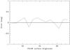 |
Fig. 3 Mean error in the surface brightness estimate as a function of the F814W surface brightness. |
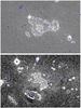 |
Fig. 4 Upper panel: F814W HST ACS image of the central area of LCDCS 0541, showing the third wavelet pass residuals. White contours correspond to levels starting at 2.5σ and increasing by 0.5σ. Blue ellipses show the classical SExtractor-detected objects (not visible since they are removed by the first two wavelet passes). The image is 1.6 × 1.6 arcmin2 wide. Lower panel: same as before using only the 1 orbit exposures. This image is zoomed on the central ICL source. The first white contour is at the 1.5σ level. |
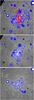 |
Fig. 5 Stacked F814W HST ACS second residual images of all ten considered clusters (upper figure), of the z ≤ 0.65 clusters (middle figure: 5 clusters taken into account), and of the z ≥ 0.70 clusters (lower figure: 5 clusters taken into account). Images are 200 × 200 kpc2 wide. The upper figure also shows as red circles the positions of the brightest cluster galaxies of the stacked clusters. |
Then we, as previously, assumed the diffuse light source to be part of the considered cluster in order to compute a distance modulus with the adopted cosmology. Finally, we k-corrected the computed absolute magnitudes with the values listed in Sect. 4.5, assuming elliptical-like colors.
Figure 5 also shows the brightest cluster galaxies of the stacked clusters. This allows us to see that the detected diffuse light sources are most of the time close to these galaxies, but not always centered on these positions.
We divided our sample into low and high redshift clusters and produced two stacked residual images for clusters at z ≤ 0.65 and z ≥ 0.70. This permitted 6σ and 8σ detections in both redshift bins (see Fig. 5). The absolute magnitudes of the diffuse light sources detected at z ≤ 0.65 and z ≥ 0.70 (−20.9 and −21.3, respectively, in the F814W filter) correspond to about two L∗ galaxies for each of the individual clusters. It is not easy, however, to express the amount of ICL as a percentage of the total cluster light, because it requires a measurement of the total cluster light. In the considered redshift range, we were only able to use photometric redshifts to define cluster membership, and the relatively large photometric redshift uncertainties ( ± 0.1: see Guennou et al. 2010) would have in turn created too large an uncertainty in the measurement of the total cluster light.
We note that in the LCDCS detection technique the clusters are detected as positive surface brightness fluctuations in the background sky. If the amount of diffuse light detected were greater than the galaxy contribution, then the detection method would preferentially identify clusters with a large amount of diffuse light. Given the moderate amount of diffuse light, this bias, even if present, should not have a strong effect.
4.2. Superflat residuals?
We verify in two ways that our ICL detections are not artefacts of the numerical image reduction. Superflat defaults may produce these sources.
A good method for verifying this is to try to redetect our ICL sources in HST F814W ACS images where they physically lie in different CCD regions. This would be possible only using the external one orbit tiles to generate the central image. This means that we would exclude the central four orbit tile and that the area where the ICL source is present will not be affected in the same way by the possible numerical artefacts. The problem is that we showed that the one orbit images are not deep enough to efficiently detect ICL sources in the most distant of our clusters. We therefore only selected LCDCS 0541, which is one of the closest structures in our sample (z = 0.54) and the structure with the second brightest detected ICL source. We analyzed for this cluster the one orbit images in the same way as the full depth image. We show the result in Fig. 4. We redetect the ICL source, as expected at a lower signal-to-noise ratio (SNR) of 1.5. The magnitude of this source is − 19.6, which is fainter than the − 20.4 value predicted by the full depth image. This is not surprising because we do not detect the external part of the ICL source with images taken during only one orbit.
Another test is to search for diffuse light in places where it is not supposed to be present. For this, we selected all the central areas (1000 × 1000 pixels) of the external one orbit tiles. These areas only cover the cluster outskirts, where we did not detect any significant ICL sources. We then added together these images disregarding their astrometry and produced in this way a very deep fake image assumed to be free of ICL sources. This image consist of 40 one-orbit tiles and provides an image quality similar to that of the full depth central images. Analyzing this fake field in the same way as previously, we produced a residual map that contains almost no significant ICL source (see Fig. 6). Numerical artefacts therefore do not seem to be a problem in our analysis.
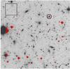 |
Fig. 6 Fake image built with the 40 external one-orbit tiles. We only show the area of 1000 × 1000 pixel2. Red contours correspond to levels starting at 2.5σ and increasing in 0.5σ intervals. The large black square represents the typical size of ICL sources detected in real images. The black circle is the only diffuse light source detected in this fake image, which is not a star residual. |
4.3. Anisotropic ICL distribution?
The stacked images presented in the previous section were obtained by assuming random orientations of the clusters. The images of the ICL were therefore, by definition, isotropic. To determine whether any preferential orientation could be identified in the spatial distribution of the ICL, we chose to rely on another measurement of the orientation, based on the substructures potentially populating the clusters (we could also have relied on the brightest cluster galaxy orientation but the goal of the present paper is not a detailed study of these galaxy characteristics). As shown in several studies (e.g. Adami et al. 2009), these substructures are good indicators of the directions in which matter is being accreted from the cosmic web, and when they are detected they appear as special orientations of the clusters.
We therefore analyzed the inner structure of the ten clusters using the Serna-Gerbal method (Serna & Gerbal 1996), which allows us to both find and study substructures in galaxy clusters based on dynamical arguments. This method adopts a hierarchical clustering analysis to determine the relationship between galaxies based on their relative binding energies (see Serna & Gerbal 1996, for a complete description of the method). To determine whether a given galaxy is part of a given cluster substructure or not, we need to know its projected position, its magnitude, and its spectroscopic redshift (see Table 1 for the number of available redshifts along the considered lines of sight). We considered only substructures containing at least three galaxies and within a redshift interval of ± 0.012 from the cluster redshift (this is ± 3 times the maximal velocity dispersion for a cluster). For two of the ten clusters, no substructures were detected. This does not mean that these clusters are fully relaxed: it is possible that our spectroscopic sampling was insufficient to detect potential substructures. For eight clusters, significant substructures were detected and we show their spatial distributions in Fig. 7.
The comparison of these subtructures with the study of Halliday et al. (2004) (based on the Dressler-Shectman test) is not straightforward. However, limiting our analysis to the clusters in common, we note that clusters with no subtructures detected with the Serna & Gerbal method are found to have no significant substructure in the Dressler-Shectman test. Conversely, all clusters for which substructures are detected with the Dressler-Shectman test also exhibit subtructures according to the Serna & Gerbal method.
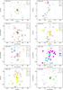 |
Fig. 7 Maps of the detected cluster substructures with different symbols and colors representing the different structures. The symbol numbers refer to each detected substructure. |
To help identify any cluster orientations, we computed histograms of the angular positions of the galaxies found to be part of substructures in the cluster (see Fig. 8). We also tried to infer the orientations directly from the ICL emission. However, these sources are quite faint and any orientation estimate has a very large uncertainty (of typically ± 70 deg). Similarly, we could have considered the orientation of the brightest cluster galaxy, but the choice of this galaxy is not always obvious. We therefore decided to rely only on the Serna-Gerbal results. Clear preferential directions appear for LCDCS 0110 (300 deg), LCDCS 0130 (220 deg), LCDCS 0172 (295 deg), LCDCS 0504 (240 deg), and LCDCS 0853 (25 deg). The orientation of LCDCS 0110 is attributed mainly to the substructure 1 (see Fig. 7). The cluster LCDCS 0130 has a principal orientation of about 130 deg mainly caused by substructures 2 and 3, and there is a secondary orientation corresponding to substructure 1 around 100 deg. The most likely orientations of LCDCS 0172 and LCDCS 0504 are produced by all their substructures. Finally, the orientation of LCDCS 0853 is mainly driven by substructure 2.
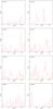 |
Fig. 8 Histograms of the angular positions of the galaxies associated with substructures in the clusters analyzed. Preferential directions appear for LCDCS 0110, LCDCS 0130, LCDCS 0172, LCDCS 0504, and LCDCS 0853 (see text). Angles are computed anticlockwise from the west. |
Adopting the orientation directions determined by the Serna-Gerbal method, we stacked the second residual images computed with the wavelet code using these same directions, and compared our results with those for the randomly oriented stack. The ratio of these two image stacks does not vary by more than 5%, which means that, there is no significant detected orientation in the ICL source distribution.
4.4. Amount of ICL as a function of cluster velocity dispersion
An obvious question is whether the amount of diffuse light detected is related to the cluster properties. We now consider ICL detections in individual clusters. The magnitudes quoted in Table 1 are obviously lower limits, only characteristic of the diffuse light we are able to detect given our instrumental configuration. We show in Fig. 9 the relation between the cluster velocity dispersions (from Halliday et al. 2004; and Milvang-Jensen et al. 2008) and the amount of diffuse light (see Table 1). We note here that these velocity dispersions are reasonably close to the Clowe et al. (2006) estimates. We see a modest increase in the F814W absolute magnitude of the diffuse light with the velocity dispersion, a trend that is mainly controlled by the two highest velocity dispersion clusters in the considered sample. In Fig. 10, we similarly show the relation between the amount of diffuse light and the cluster mass. We estimated the mass (see Table 1) using the velocity dispersions and Eq. (6) of Evrard et al. (2008). We still see a modest increase in the total F814W absolute magnitude of the diffuse light with mass, mainly because of the two highest mass clusters. We attempted to identify any obvious relation between the cluster M/L and the amount of ICL. We were unable to find any clear trend (see Fig. 11) and simply note that the amount of dark matter in a cluster does not appear to strongly influence the amount of material expelled from galaxies that probably forms the ICL (see also below). This is in good agreement with the simulations of Dolag et al. (2010), which do not predict any significant relation between the cluster mass and the fraction of diffuse light in clusters.
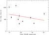 |
Fig. 9 Relation between the cluster velocity dispersions from Halliday et al. (2004) and Milvang-Jensen et al. (2008) and the amount of diffuse light in the F814W band. The red line has a slope of − 85 km s-1 mag-1. This figure does not show the low redshift clusters seen in Fig. 12. |
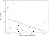 |
Fig. 10 Relation between the cluster M200 mass computed from velocity dispersions from Table 1 and the amount of diffuse light in the F814W-band. The red line has a slope of − 1.85. This figure does not show the two low-redshift clusters seen in Fig. 12. |
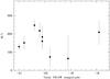 |
Fig. 11 Relation between the cluster M/L from Clowe et al. (2006) and the total magnitude of the diffuse light in the F814W-band. This figure does not show the low redshift clusters seen in Fig. 12. |
4.5. Comparison with low redshift detections
We now place our results in perspective with our previous studies of less distant clusters, namely Coma and A2667 (see Adami et al. 2005; and Covone et al. 2006a, respectively). The detection of diffuse light in these two structures has been made with the same wavelet method and the results are therefore directly comparable. In Coma (z = 0.023), Adami et al. detected diffuse light sources equivalent to a − 22.6 galaxy in the F814W filter. This value was estimated by translating the Adami et al. (2005) R band Vega value to an F814W AB value using the Fukugita et al. (1995) k-corrections (0.05 mag at the Coma cluster redshift) and elliptical galaxy colors. In A2667 (z = 0.233), we detected diffuse light sources equivalent to a − 21.12 galaxy in the F814W filter (adopted k-correction: 0.25 mag).
These values allow us to search for any evolution in the amount of ICL in clusters between z ~ 0.8 and z = 0. Before trying to plot the amount of ICL in clusters as a function of redshift, we must correct for the dependence on velocity dispersion and mass discernible in Figs. 9 and 10. The best-fit relation between the velocity dispersion σv (respectively the mass) and the absolute magnitude of the diffuse light in the F814W filter is  and
and  If we assume that the same relation applies to Coma and A2667 (adopting velocity dispersions of 1200 km s-1 for Coma from Adami et al. 2009; and 960 km s-1 for A2667 from Covone et al. 2006b), we can correct for the differences in velocity dispersion between all the clusters considered here. Adopting the cluster masses of Kubo et al. (2007) and Ota & Mitsuda (2004) for Coma and A2667, we can also correct for any dependence on mass. We show in Fig. 12 the variation in the total (rest-frame) ICL magnitude versus redshift. We see no strong variation in the amount of ICL for the clusters between z = 0 and z = 0.8, especially when considering the mass-corrected values, besides perhaps a modest increase with redshift.
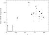 |
Fig. 12 Relation between the total magnitude of the diffuse light in the F814W band and the cluster redshift. Filled symbols are raw values. Open circles are the ICL total F814W magnitudes corrected for the effects of velocity dispersion. Crosses are the values corrected for the effects of mass. The large square at the bottom left of the figure represents the locus occupied by intracluster light detected in the González et al. (2005) low-redshift clusters (see text). |
Several other studies have been performed at low redshift, some of which are based on galaxy subtraction via their shape modeling (e.g. González et al. 2007; Krick & Bernstein 2007; Rudick et al. 2010). These studies sometimes predict more diffuse light in structures than the studies based on the wavelet method (e.g. Adami et al. 2005; Covone et al. 2006a; Da Rocha et al. 2008).
For example, we can use the results of González et al. (2005) to make this comparison. By fitting several profiles of the brightest galaxies of 24 z = [0.03, 0.13] galaxy clusters, these authors estimated the total magnitude included within several radii. This definition differs from the one adopted here (we do not use, for example, any parametric model of the diffuse light). However, we can adapt these values by removing the amount of light included in the 10 kpc radius from the value included in the 50 kpc radius of González et al. (2005) (see their Table 6). Assuming a k-correction factor of 0.07 (González et al. 2005), a F814W-I of 0.04 (Fukugita et al. 1995), and an AB-Vega correction factor of 0.46, we then plot in Fig. 12 the locus occupied by the González et al. (2005) clusters. The diffuse light values are somewhat brighter than our present detections, perhaps because our typical ICL sources radii are close to 20 kpc, hence less extended than the 50 kpc radii of González et al. (2005).
5. Nature of the wavelet-detected sources
5.1. ICL sources
An important question is whether the diffuse light that we have detected consists of either stars or diffuse gas. A common assumption is that it consist of old stars expelled from disrupted or partially disrupted galaxies. For example, Adami et al. (2005) discuss this and show that the diffuse light in Coma has colors that closely agree with those of quite old stellar populations. However, could this diffuse light be produced by hot intra-cluster diffuse gas?
The bremsstrahlung emission of the hot gas commonly detected in X-rays might also be detectable at optical wavelengths. It is therefore interesting to compare the surface brightness we have observed for the ICL with the predicted value for hot gas in a cluster with an X-ray luminosity similar to that of our sample. We selected the Coma cluster and carried out an order of magnitude estimate based on Lutovinov et al. (2008). Within a 10 arcmin radius, they found about half the total X-ray luminosity (total flux = 4.4 × 10⁻¹⁰ erg cm-2 s-1). We then used the PIMMs code (see http://heasarc.nasa.gov/docs/software/tools/pimms.html) to convert the 50% total luminosity to 2.5 − 3 eV (approximately B band) and a 10 arcmin radius to derive a surface brightness of about 1.13 × 10⁻¹⁶ erg cm-2 s-1 for an area of 300 arcmin2. We then converted this to AB B magnitudes using IDL to obtain a value of about 34 mag (AB)/arcsec-2 (the typical values of our ICL sources are ~27 mag/arcsec2). We also found similar values for the V and I bands, for which brightnesses are much fainter than those we can detect. Therefore, the optical tail of the thermal bremsstrahlung responsible for the cluster X-ray emission cannot account for the ICL emission that we measure.
Hence, the most likely interpretation is that we observe stars expelled from cluster galaxies located at the bottom of the cluster potential well.
Additional arguments for the ICL consisting of stars are firstly that the intracluster supernova rates are consistent with the size of this population of stars (Sand et al. 2011), where the baryon budget is close to the WMAP universal value if one adopts a standard stellar M/L for this light (including stars in galaxies and hot plasma; cf. González et al. 2007), and secondly that stars (PNe and red giants) have been detected in-between galaxies in clusters (cf. Arnaboldi et al. 2010). We also note that our V-band images are deep enough to detect WDCOs (see next section) for not too distant clusters, but are insufficiently deep and have an unadapted background subtraction to detect ICL sources. We therefore do not have access to the colors of the ICL sources detected in our F814W images.
5.2. Wavelet-detected compact objects (WDCOs)
During its first two passes, the wavelet detection process appears to detect very faint objects in the HST ACS F814W images, that are sometimes not detected by classical SExtractor searches (unless we use very low thresholds (as low as 0.3), which would lead to numerous fake detections). These faint objects could be fake detections, and even if real cannot be characterised reliably using data in a single band. To check whether these objects are real and investigate their nature, we analyzed the three lowest redshift clusters in our LCDCS sample for which our ground-based V-band images are deep enough. We then selected only WDCOs detected in both the V and F814W images. These WDCOs are most probably real and not caused by random background fluctuations.
To see whether these objects are peculiarly distributed in color − magnitude plots (see Fig. 13), we have to compare them with deep sky catalogs. These catalogs must include V and F814W-like magnitudes in order not to be biased by different bands, thus excluding for example deep fields observed with SDSS filters. They must also be deep enough to be comparable with our own V and F814W data. We chose to use the VIRMOS deep imaging survey two-hours field (see e.g. McCracken et al. 2003). This field was observed in the B, V (very close to our own V band), R, and I bands at the CFHT telescope with the CFH12K camera. Our F814W band can easily be mimicked by the I band at the cost of a ~0.1 mag shift, which is nearly constant as a function of redshift and galaxy type (Fukugita et al. 1995). Moreover, the VIRMOS deep imaging survey two-hours field is one of the very rare fields deep enough to be comparable with our data. Figure 9 of McCracken et al. (2003) shows that the detection rate is still non-negligible at I ~ 26.5/27, even though beyond the 90% completeness magnitude. We therefore plot in Fig. 13 the mean V − F814W color of the VIRMOS deep imaging survey field as well as its 3σ uncertainty, between F814W = 24 and 27. The involved color ranges are in perfect agreement with most of the WDCOs.
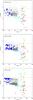 |
Fig. 13 Color–magnitude diagram V − F814W versus F814W for the three considered clusters. Black dots represent the SExtractor-detected objects along the considered lines of sight. Blue-filled hexagons are the SExtractor-detected objects in each cluster according to their spectroscopic redshift. Triangles are WDCOs with a χ2 lower than 8, crosses with a χ2 between 8 and 10, pentagons with a χ2 between 10 and 15, and small dots with higher χ2 values. For these last four classes, red is the color for WDCOs detected in the first pass and green in the second pass. The red lines limit the space in which the objects are likely to belong to the cluster. The large cyan filled-circles with error bars are the locus of galaxies in the VIRMOS field (see text). The values of these four cyan circles were computed (from left to right) with 29 689, 35 804, 4788, and 511 galaxies. The large cyan open-triangles with error bars represent the galaxies in the VIRMOS field with mean surface brightness typical of the first pass WDCOs. The large cyan crosses without error bars are the galaxies in the VIRMOS field with mean surface brightnesses typical of the second pass WDCOs. |
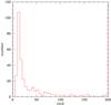 |
Fig. 14 Histogram of the reduced χ2 values obtained by merging the results for the three clusters. |
However, the objects in the VIRMOS deep images may occupy a different locus in a mean surface brightness versus total magnitude plane compared to our WDCOs. We estimated the mean surface brightnesses of our first and second pass WDCOs in the same way as the surface brightnesses computed for the VIRMOS deep imaging survey two-hour field. This was done by setting a low detection threshold in SExtractor and by keeping only the detections occupying on the WDCO positions. We then computed the mean surface brightnesses of these objects with the parameters estimated by SExtractor in an area defined by three times the minor and major axes. First (resp. second) pass WDCOs then have SExtractor-estimated mean surface brightnesses of 25.2 ± 0.53 (resp. 25.6 ± 0.45). We applied these two surface brightness selections to the VIRMOS deep imaging survey two hour field catalog before recomputing the V − F814W colors. Figure 13 shows that WDCOs still do not appear to have atypical colors.
However, the VIRMOS deep imaging survey field does not include very massive clusters (see e.g. Adami et al. 2011). To compare the WDCO colors with very faint galaxies of massive clusters, we defined an approximate locus for the red-sequence in the WDCO regime assuming the mean V − F814W color from faint cluster member galaxies defined in a deep Coma-cluster spectroscopic redshift catalog (see Adami et al. 2009). We assumed a 1σ red envelope width of 0.7 at magnitudes between F814W = 26 and 28 (leading to a 3σ width of ± 2.1), based on the typical cluster red-sequence 1σ width for Coma at R = 22 being close to 0.5 (see Adami et al. 2009). Given the lack of knowledge of the red-sequence width at F814W ≥ 26, we adopted the simplest approach of considering a horizontal envelope for the red sequence. We see in Fig. 13 that part of the WDCOs are also located on the red-sequence defined above. The WDCOs with colors consistent with the cluster red-sequence could therefore be small, very faint, compact galaxies and members of the considered clusters (at least part of them).
We also note that most of the WDCOs are more than one magnitude fainter than the SExtractor detection limit, and remarkably, nearly none of them are brighter than this limit. Therefore, they appear to be an independent population in the three considered clusters or might also be atypically faint Galactic stars. We cannot use SExtractor to make a classification since these WDCOs are by definition not detected by this code. We are similarly unable to place the WDCOs in a central magnitude versus total magnitude plot because WDCOs usually have very irregular brightness profiles, hence a reliable computation of the central brightness is impossible. We therefore fitted a two-dimensional Gaussian with an added constant background to each of the WDCO images. We assumed that the full-width at half maximum (FWHM) of the Gaussian was the HST ACS spatial resolution and only allowed the level of the background and the amplitude of the Gaussian to vary. We show in Fig. 14 the histogram of the reduced χ2 computed for the best fits.
All objects have quite large reduced χ2 values, making them very unlikely to be faint stars. Even the lowest reduced χ2 values are on the order of 8, much too high for this population to be dominated by objects limited by the instrumental resolution.
We now consider the redshifts of these WDCOs: are they part of the considered clusters? It is obviously impossible to measure their spectroscopic redshifts with the telescopes presently available. Photometric redshifts are also impossible to compute because these objects are only detected in two bands and our photometry in the other optical bands is insufficiently deep. Beyond the color − magnitude relations already discussed, another way to investigate the cluster membership of these objects is then to study their spatial distribution. If cluster members in part, WDCOs should at least partially follow the light of the cluster potential well. Figure 15 clearly displays this behavior. To generate this figure, we used an adaptive kernel technique (e.g. Adami et al. 1998) and computed the projected density map on the sky of all the detected WDCOs along the line of sight. We selected a structure-free area and computed the 1σ variation in the WDCO density. Dividing the original WDCO density map by this value, this produced Fig. 15, which is expressed in units of this 1σ variation. We clearly see a central concentration on a scale typical of a cluster (we used the mean redshift of the considered clusters to give Fig. 15 in units of kpc). If WDCOs are real, this implies that these objects are cluster members.
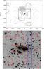 |
Fig. 15 Upper figure: stacked physical spatial map of the WDCOs detected in the clusters analyzed in both V and F814W bands. Density contours start at the 3σ level and are in steps of 1σ. The area limited by the inner square is shown in the lower figure. Lower figure: stacked and rescaled images of LCDCS 0110, LCDCS 0340, and LCDCS 0541 (see text). Red circles are the detected WDCOs. The two blue lines delimit a lower signal to noise region. |
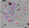 |
Fig. 16 Example of external area around LCDCS 0110. The field shown is 1.65′ wide and represents a physical area similar to Fig. 15 (bottom). Red circles are the detected WDCOs. Blue contours show the WDCO surface density, starting at the 3σ level and are in steps of 1σ. |
Although the considered WDCOs are detected in two different bands observed with two different instruments, it could be argued that because they are such low SNR detection they could well be purely noise at least partly occurring at the edges of bright objects and/or in noisy regions. We would then naturally expect these “spurious” detections to be located close to the haloes of bright objects. They would then follow the cluster profile and this could explain why their spatial distribution is centrally concentrated. However, we first note that the spatial distribution of WDCOs is not exactly centered on the cluster centers: a ~200 kpc shift is seen in Fig. 15. Second, Fig. 15 also shows the location of the WDCOs in the stacked central cluster regions. We made the sum of the images of LCDCS 0110, LCDCS 0340, and LCDCS 0541 after centering each image on the cluster center and rescaling to physical units (kpc). While a few of the WDCOs are indeed located in the vicinity of bright objects and may well be spurious objects, the vast majority of WDCOs appears to be far from any bright object. Moreover, the higher noise part of images shown in Fig. 15 exhibits only two WDCOs. It is therefore very likely that the vast majority of our WDCOs are not of spurious detections.
We made a last test: in the external parts of our deep HST images of LCDCS 0110, we considered a region populated with bright objects (including stars), but without any known cluster. If WDCOs were spurious objects wrongly detected at the edges of bright objects, we should then detect significant concentrations of WDCOs in these areas around bright objects, despite the absence of any cluster. Figure 16 clearly shows that we have no specific correlation of WDCOs with bright objects (stars or bright galaxies). The density of WDCOs in this area is globally lower than in the central regions: the most significant concentrations detected in this area are found at the 5σ level, while Fig. 15 shows concentrations at the 10σ level.
We therefore believe that our WDCOs are most probably not spurious detections and that some of them are likely to be cluster members.
Finally, we compared these WDCOs with some very faint galaxies in the Local Group (e.g. Massey et al. 2007) to check whether these galaxies have similar stellar populations. The Massey et al. Local Group dwarf galaxies have typical V-band magnitudes between − 13 and − 14, in good agreement with the dwarf absolute magnitudes computed from our color − magnitude plots when we assume that WDCOs on the red-sequence are part of the considered clusters. It is therefore likely that some of these WDCOs are dwarf galaxies similar to faint Local Group dwarfs.
6. Summary
To help us analyse the mechanisms taking place in galaxy clusters, and place constraints on their formation history and physical properties, we have searched for intracluster light (ICL) in ten galaxy clusters at redshifts 0.4 < z < 0.8. For the first time, we have detected significant diffuse light sources in an unprecedentedly high redshift bin z = [0.4, 0.8] based on very deep HST ACS images to which we have applied a very sensitive wavelet detection method. Until now, most searches and detailed studies of ICL emission have been limited to redshifts z < 0.4 because of the intrinsic faintness of ICL emission, so our study represents a significant step forward in measuring any ICL evolution with redshift.
Our analysis has applied a wavelet code (see e.g. Pereira 2003; and Da Rocha & Mendes de Oliveira 2005) to deep HST ACS images in the F814W filter and V-band VLT/FORS2 images (for three of the ten clusters). Detection levels have been assessed as a function of the surface brightnesses of the diffuse light sources via simulations.
In the F814W filter, we have detected diffuse light sources in all the clusters with typical sizes of a few tens of kpc (assuming that the diffuse light sources are at the cluster redshifts). The ICL detected by stacking the ten F814W images shows a very clear 8σ detection at the source center extending over a ~50 × 50 kpc2 area. The total absolute magnitude of this source is −21.6 in the F814W filter, equivalent to about two L∗ galaxies for each of the ten clusters.
We have also discussed the possible anisotropy of the ICL distribution and the existence of substructures in the inner regions of the clusters. We have found a weak correlation between the total F814W absolute magnitude of the ICL and both the velocity dispersion and the mass. No correlation was found between the cluster M/L and the amount of ICL (in agreement with Dolag et al. 2010), and there is no evidence of any special orientation in the ICL source distributions. We have found no strong variation in the amount of ICL between z = 0 and z = 0.8, besides perhaps a modest increase.
Finally, besides the extended ICL, we have also found wavelet-detected compact objects (WDCOs). Since these sources are very faint, we only considered those detected in both the HST/ACS/F814W and FORS2/V-band filters, in the three clusters for which sufficiently deep data in both bands are available. The fit of a two-dimensional Gaussian plus a constant background on each of the WDCO images suggests that they are very unlikely to be faint Galactic stars. On the other hand, some of the WDCOs are located on the cluster red-sequences in color − magnitude diagrams and their spatial distribution also suggests that they could be very faint compact galaxies belonging to the considered clusters and comparable to faint Local Group dwarfs.
See http://cencos.oamp.fr/DAFT/ and Guennou et al. (2010) for details.
This is based on total magnitudes and an analysis performed at the 1.8σ and 3σ SExtractor levels, respectively, for the deep and shallow parts to limit fake object detections.
Acknowledgments
The authors thank the referee for useful and constructive comments. We thank the French PNCG/CNRS for support in 2010. We also
thank A. Cappi, J.G. Cuby, C. Ferrari, J. P. Kneib, R. Malina, S. Maurogordato, and C. Schimd for their help. T.S. acknowledges support from the Netherlands Organization for Scientific Research (NWO), from NSF through grant AST-0444059-001, and from the Smithsonian Astrophysics Observatory through grant GO0-11147A.
References
- Adami, C., Mazure, A., Katgert, P., & Biviano, A. 1998, A&A, 336, 63 [NASA ADS] [Google Scholar]
- Adami, C., Slezak, E., Durret, F., et al. 2005, A&A, 429, 39 [NASA ADS] [CrossRef] [EDP Sciences] [Google Scholar]
- Adami, C., Scheidegger, R., Ulmer, M. P., et al. 2006, A&A, 459, 679 [NASA ADS] [CrossRef] [EDP Sciences] [Google Scholar]
- Adami, C., Le Brun, V., Biviano, A., et al. 2009, A&A, 507, 1225 [NASA ADS] [CrossRef] [EDP Sciences] [Google Scholar]
- Adami, C., Mazure, A., Pierre, M., et al. 2011, A&A, 526, A18 [NASA ADS] [CrossRef] [EDP Sciences] [Google Scholar]
- Anderson, J. 2007, Instrument Science Rep. ACS 2007-08 (Baltimore: STScI), http://www.stsci.edu/hst/acs/documents/isrs/isr0708.pdf, Variation of the Distortion Solution of the WFC [Google Scholar]
- Arnaboldi, M., & Gerhard, O. 2010, HiA, 15, 97 [Google Scholar]
- Bernstein, G. M., Nichol, R. C., Tyson, J. A., et al. 1995, AJ, 110, 1507 [NASA ADS] [CrossRef] [Google Scholar]
- Bertin, E., & Arnouts, S. 1996, A&A, 117, 393 [Google Scholar]
- Clowe, D., Schneider, P., Aragon-Salamanca, A., et al. 2006, A&A, 451, 395 [NASA ADS] [CrossRef] [EDP Sciences] [Google Scholar]
- Covone, G., Adami, C., Durret, F., et al. 2006a, A&A, 460, 381 [NASA ADS] [CrossRef] [EDP Sciences] [Google Scholar]
- Covone, G., Kneib, J. P., Soucail, G., et al. 2006b, A&A, 456, 409 [NASA ADS] [CrossRef] [EDP Sciences] [Google Scholar]
- Da Rocha, C., & Mendes de Oliveira, C. 2005, MNRAS, 364, 1069 [NASA ADS] [CrossRef] [Google Scholar]
- Desai, V., Dalcanton, J. J., Aragón-Salamanca, A., et al. 2007, ApJ, 660, 1151 [NASA ADS] [CrossRef] [Google Scholar]
- Dolag, K., Murante, G., & Borgani, S. 2010, MNRAS, 405, 1544 [NASA ADS] [Google Scholar]
- Evrard, A. E., Bialek, J., Busha, M., et al. 2008, ApJ, 672, 122 [NASA ADS] [CrossRef] [Google Scholar]
- Fukugita, M., Shimasaku, K., & Ichikawa, T. 1995, PASP, 107, 945 [NASA ADS] [CrossRef] [Google Scholar]
- González, A. H., Zaritsky, D., Dalcanton, J. J., & Nelson, A. 2001, ApJS, 137, 117 [NASA ADS] [CrossRef] [Google Scholar]
- González, A. H., Zabludoff, A. I., & Zaritsky, D. 2005, ApJ, 618, 195 [Google Scholar]
- González, A. H., Zaritsky, D., & Zabludoff, A. I. 2007, ApJ, 666, 147 [NASA ADS] [CrossRef] [Google Scholar]
- Gregg, M. D., & West, M. J. 1998, Nature, 396, 549 [NASA ADS] [CrossRef] [Google Scholar]
- Guennou, L., Adami, C., Ulmer, C., et al. 2010, A&A, 523, A21 [NASA ADS] [CrossRef] [EDP Sciences] [Google Scholar]
- Halliday, C., Milvang-Jensen, B., Poirier, S., et al. 2004, A&A, 427, 397 [NASA ADS] [CrossRef] [EDP Sciences] [Google Scholar]
- Ilbert, O., Arnouts, S., McCracken, H. J., et al. 2006, A&A, 457, 841 [NASA ADS] [CrossRef] [EDP Sciences] [Google Scholar]
- Koekemoer, A. M., Fruchter, A. S., Hook, R. N., & Hack, W. 2002, The 2002 HST Calibration Workshop, ed. S. Arribas, A. Koekemoer, & B. Whitmore (Baltimore: STScI), 337 [Google Scholar]
- Krick, J. E., & Bernstein, R. A. 2007, AJ, 134, 466 [Google Scholar]
- Kubo, J. M., Stebbins, A., Annis, J., et al. 2007, ApJ, 671, 1466 [NASA ADS] [CrossRef] [Google Scholar]
- Lutovinov, A. A., Vikhlinin, A., Churazov, E. M., Revnivtsev, M. G., & Sunyaev, R. A. 2008, ApJ, 687, 968 [NASA ADS] [CrossRef] [Google Scholar]
- Massey, P., Olsen, K. A. G., Hodge, P. W., et al. 2007, AJ, 133, 2393 [NASA ADS] [CrossRef] [MathSciNet] [Google Scholar]
- McCracken, H. J., Radovich, M., Bertin, E., et al. 2003, A&A, 410, 17 [NASA ADS] [CrossRef] [EDP Sciences] [Google Scholar]
- Mihos, J. C., Harding, P., Feldmeier, J., & Morrison, H. 2005, ApJ, 631, L41 [NASA ADS] [CrossRef] [Google Scholar]
- Milvang-Jensen, B., Noll, S., Halliday, C., et al. 2008, A&A, 482, 419 [NASA ADS] [CrossRef] [EDP Sciences] [Google Scholar]
- Ota, N., & Mitsuda, K. 2004, A&A, 428, 757 [NASA ADS] [CrossRef] [EDP Sciences] [Google Scholar]
- Pereira, D. N. E. 2003, Undergraduate thesis, Univ. Federal do Rio de Janeiro, Brazil [Google Scholar]
- Rudick, C. S., Mihos, J. C., Harding, P., et al. 2010, ApJ, 720, 569 [NASA ADS] [CrossRef] [Google Scholar]
- Rué, F., & Bijaoui, A. 1997, Exp. Astron., 7, 129 [Google Scholar]
- Sand, D. J., Graham, M. L., Bildfell, C., et al. 2011, ApJ, 729, 142S [NASA ADS] [CrossRef] [Google Scholar]
- Schrabback, T., Hartlap, J., Joachimi, B., et al. 2010, A&A, 516, A63 [NASA ADS] [CrossRef] [EDP Sciences] [Google Scholar]
- Serna, A., & Gerbal, D. 1996, A&A, 309, 65 [NASA ADS] [Google Scholar]
- Starck, J.-L., & Murtagh, F. D. 2002, Astronomical Image and Data Analysis (Springer) [Google Scholar]
- Starck, J.-L., Murtagh, F. D., & Bijaoui, A. 1998, Image Processing and Data Analysis (Cambridge, UK: Cambridge University Press) [Google Scholar]
- Toledo, I., Melnick, J., Selman, F., et al. 2011, MNRAS, 414, 602 [NASA ADS] [CrossRef] [Google Scholar]
- Uson, J. M., Boughn, S. P., & Kuhn, J. R. 1991, ApJ, 369, 46 [NASA ADS] [CrossRef] [Google Scholar]
- White, S. D. M., Clowe, D. I., Simard, L., et al. 2005, A&A, 444, 365 [NASA ADS] [CrossRef] [EDP Sciences] [Google Scholar]
- Zibetti, S., White, S. D. M., Schneider, D. P., & Brinkmann, J. 2005, MNRAS, 358, 949 [Google Scholar]
All Tables
Main characteristics of the ten clusters observed, and total ICL F814W absolute magnitudes.
All Figures
|
Fig. 1 1.1 × 1.1 arcmin2 images of the various steps of the wavelet analysis for LCDCS 0541. Upper left: sky image; upper right: first pass objects; lower left: second pass objects; lower right: final residual image. |
| In the text | |
|
Fig. 2 Upper panel: percentage of recovered diffuse light sources in HST ACS images. Curves to the right are related to the wavelet detections. Curves to the left are relative to the SExtractor detections. Dotted curves are relative to shallow HST ACS image areas. Continuous curves are relative to deep HST ACS image areas. The two vertical lines show the brightest Coma cluster known diffuse light source (a ~ 60 kpc wide source) redshifted to z = 0.4 and z = 0.8. Lower panel: percentage of recovered diffuse light sources in FORS2 V-band images. The two vertical lines show the brightest known Coma cluster diffuse light source redshifted to z = 0.4 and z = 0.8. All curves correspond to the wavelet detection. The continuous curve represents very blue objects (V − F814W = 1), the dotted curve blue objects (V − F814W = 2.1), and the dashed curve red objects (V − F814W = 2.6). |
| In the text | |
|
Fig. 3 Mean error in the surface brightness estimate as a function of the F814W surface brightness. |
| In the text | |
|
Fig. 4 Upper panel: F814W HST ACS image of the central area of LCDCS 0541, showing the third wavelet pass residuals. White contours correspond to levels starting at 2.5σ and increasing by 0.5σ. Blue ellipses show the classical SExtractor-detected objects (not visible since they are removed by the first two wavelet passes). The image is 1.6 × 1.6 arcmin2 wide. Lower panel: same as before using only the 1 orbit exposures. This image is zoomed on the central ICL source. The first white contour is at the 1.5σ level. |
| In the text | |
|
Fig. 5 Stacked F814W HST ACS second residual images of all ten considered clusters (upper figure), of the z ≤ 0.65 clusters (middle figure: 5 clusters taken into account), and of the z ≥ 0.70 clusters (lower figure: 5 clusters taken into account). Images are 200 × 200 kpc2 wide. The upper figure also shows as red circles the positions of the brightest cluster galaxies of the stacked clusters. |
| In the text | |
|
Fig. 6 Fake image built with the 40 external one-orbit tiles. We only show the area of 1000 × 1000 pixel2. Red contours correspond to levels starting at 2.5σ and increasing in 0.5σ intervals. The large black square represents the typical size of ICL sources detected in real images. The black circle is the only diffuse light source detected in this fake image, which is not a star residual. |
| In the text | |
|
Fig. 7 Maps of the detected cluster substructures with different symbols and colors representing the different structures. The symbol numbers refer to each detected substructure. |
| In the text | |
|
Fig. 8 Histograms of the angular positions of the galaxies associated with substructures in the clusters analyzed. Preferential directions appear for LCDCS 0110, LCDCS 0130, LCDCS 0172, LCDCS 0504, and LCDCS 0853 (see text). Angles are computed anticlockwise from the west. |
| In the text | |
|
Fig. 9 Relation between the cluster velocity dispersions from Halliday et al. (2004) and Milvang-Jensen et al. (2008) and the amount of diffuse light in the F814W band. The red line has a slope of − 85 km s-1 mag-1. This figure does not show the low redshift clusters seen in Fig. 12. |
| In the text | |
|
Fig. 10 Relation between the cluster M200 mass computed from velocity dispersions from Table 1 and the amount of diffuse light in the F814W-band. The red line has a slope of − 1.85. This figure does not show the two low-redshift clusters seen in Fig. 12. |
| In the text | |
|
Fig. 11 Relation between the cluster M/L from Clowe et al. (2006) and the total magnitude of the diffuse light in the F814W-band. This figure does not show the low redshift clusters seen in Fig. 12. |
| In the text | |
|
Fig. 12 Relation between the total magnitude of the diffuse light in the F814W band and the cluster redshift. Filled symbols are raw values. Open circles are the ICL total F814W magnitudes corrected for the effects of velocity dispersion. Crosses are the values corrected for the effects of mass. The large square at the bottom left of the figure represents the locus occupied by intracluster light detected in the González et al. (2005) low-redshift clusters (see text). |
| In the text | |
|
Fig. 13 Color–magnitude diagram V − F814W versus F814W for the three considered clusters. Black dots represent the SExtractor-detected objects along the considered lines of sight. Blue-filled hexagons are the SExtractor-detected objects in each cluster according to their spectroscopic redshift. Triangles are WDCOs with a χ2 lower than 8, crosses with a χ2 between 8 and 10, pentagons with a χ2 between 10 and 15, and small dots with higher χ2 values. For these last four classes, red is the color for WDCOs detected in the first pass and green in the second pass. The red lines limit the space in which the objects are likely to belong to the cluster. The large cyan filled-circles with error bars are the locus of galaxies in the VIRMOS field (see text). The values of these four cyan circles were computed (from left to right) with 29 689, 35 804, 4788, and 511 galaxies. The large cyan open-triangles with error bars represent the galaxies in the VIRMOS field with mean surface brightness typical of the first pass WDCOs. The large cyan crosses without error bars are the galaxies in the VIRMOS field with mean surface brightnesses typical of the second pass WDCOs. |
| In the text | |
|
Fig. 14 Histogram of the reduced χ2 values obtained by merging the results for the three clusters. |
| In the text | |
|
Fig. 15 Upper figure: stacked physical spatial map of the WDCOs detected in the clusters analyzed in both V and F814W bands. Density contours start at the 3σ level and are in steps of 1σ. The area limited by the inner square is shown in the lower figure. Lower figure: stacked and rescaled images of LCDCS 0110, LCDCS 0340, and LCDCS 0541 (see text). Red circles are the detected WDCOs. The two blue lines delimit a lower signal to noise region. |
| In the text | |
|
Fig. 16 Example of external area around LCDCS 0110. The field shown is 1.65′ wide and represents a physical area similar to Fig. 15 (bottom). Red circles are the detected WDCOs. Blue contours show the WDCO surface density, starting at the 3σ level and are in steps of 1σ. |
| In the text | |
Current usage metrics show cumulative count of Article Views (full-text article views including HTML views, PDF and ePub downloads, according to the available data) and Abstracts Views on Vision4Press platform.
Data correspond to usage on the plateform after 2015. The current usage metrics is available 48-96 hours after online publication and is updated daily on week days.
Initial download of the metrics may take a while.