| Issue |
A&A
Volume 638, June 2020
|
|
|---|---|---|
| Article Number | A19 | |
| Number of page(s) | 17 | |
| Section | Interstellar and circumstellar matter | |
| DOI | https://doi.org/10.1051/0004-6361/202037774 | |
| Published online | 03 June 2020 | |
Submillimetre water masers at 437, 439, 471, and 474 GHz towards evolved stars
APEX observations and radiative transfer modelling★
1
Department of Space, Earth and Environment, Chalmers University of Technology, Onsala Space Observatory,
43992
Onsala,
Sweden
e-mail: per.bergman@chalmers.se
2
European Southern Observatory,
Karl-Schwarzschild-Str. 2,
85748
Garching,
Germany
e-mail: ehumphre@eso.org
3
Joint ALMA Observatory,
Av. Alonso de Cordova 3107,
Vitacura,
Santiago, Chile
Received:
19
February
2020
Accepted:
28
March
2020
Aims. Here we aim to characterise submillimetre water masers at 437, 439, 471, and 474 GHz towards a sample of evolved stars.
Methods. We used the Atacama Pathfinder Experiment (APEX1) to observe submillimetre water transitions and the CO (4–3) line towards 11 evolved stars. The sample included semi-regular and Mira variables, plus a red supergiant star. We performed radiative transfer modelling for the water masers. We also used the CO observations to determine mass loss rates for the stars.
Results. From the sample of 11 evolved stars, 7 display one or more of the masers at 437, 439, 471, and 474 GHz. We therefore find that these masers are common in evolved star circumstellar envelopes. The fact that the maser lines are detected near the stellar velocity indicates that they are likely to originate from the inner circumstellar envelopes of our targets. We tentatively link the presence of masers to the degree of variability of the target star, that is, masers are more likely to be present in Mira variables than in semi-regular variables. We suggest that this indicates the importance of strong shocks in creating the necessary conditions for the masers. Typically, the 437 GHz line is the strongest maser line observed among those studied here. We cannot reproduce the above finding in our radiative transfer models. In general, we find that maser emission is very sensitive to dust temperature in the lines studied here. To produce strong maser emission, the dust temperature must be significantly lower than the gas kinetic temperature. In addition to running grids of models in order to determine the optimum physical conditions for strong masers in these lines, we performed smooth wind modelling for which we cannot reproduce the observed line shapes. This also suggests that the masers must originate predominantly from the inner envelopes.
Key words: stars: AGB and post-AGB / masers / submillimeter: stars / stars: winds, outflows
Based on observations with the Atacama Pathfinder EXperiment (APEX) telescope under programme IDs 091.F-9329, 093.F-9315, and 095.F-9313. APEX is a collaboration between the Max Planck Institute for Radio Astronomy, the European Southern Observatory, and the Onsala Space Observatory. Swedish observations on APEX are supported through Swedish Research Council grant number 2017−00648.
© ESO 2020
1 Introduction
Single-dish telescopes and radio interferometers have been used to perform detailed studies of circumstellar water masers at 22 GHz towards evolved stars. Observations show that 22 GHz masers typically probe regions in which stellar wind formation and acceleration is taking place (e.g. Bains et al. 2003; Richards et al. 2012), and that they are common towards oxygen-rich evolved stars. Surveys at 183, 321, 325, and 658 GHz (Menten & Melnick 1991; Menten & Young 1995; Yates et al. 1995; Yates & Cohen 1996; Gonzalez-Alfonso et al. 1998; Hunter et al. 2007; Humphreys et al. 2017; Baudry et al. 2018) indicate that millimetre and submillimetre H2O masers are also common in circumstellar envelopes (CSEs) of evolved stars, namely asymptotic giant branch (AGB) stars and red supergiants. Submillimetre water maser observations may therefore help in the determination of quantities needed to understand the AGB mass-loss process such as gas temperature and density, kinematics, and magnetic field estimation. The first subarcsecond imaging of submillimetre water masers at 321, 325, and 658 GHz towards an evolved star, the red supergiant VY CMa, was performed by Richards et al. (2014).
The water maser frequencies selected for observation here are those at 437, 439, 471, and 474 GHz. To date, these maser lines have not been widely studied. Maser emission in the 439 and 471 GHz transitions was discovered by Melnick et al. (1993) using the Caltech Submillimeter Observatory towards three star-forming regions G34.3-0.2, W49N, and Sgr B2, and an evolved star, the AGB star U Her. The 437 GHz line was additionally detected towards U Her, but not towards the star-forming regions. The 474 GHz line was detected towards VY CMa and the AGB star W Hya using the APEX FLASH receiver (Menten et al. 2008). For extragalactic objects, Humphreys et al. (2005) made a tentative detection of the 439 GHz maser towards the active galactic nuclei (AGN) and starburst galaxy NGC 3079 using the James Clerk Maxwell Telescope. New observations therefore constitute pathfinder observations for evolved stars and AGNs using the Atacama Large Millimeter/submillimeter Array Band 8 receiver.
The 437, 439, 471, and 474 GHz lines are potentially of high interest for the investigation of CSEs if common and strong. Whereas masers at 22, 183, and 325 GHz originate from the water ‘back-bone’ levels, masers at 437, 439, 471, and 474 GHz originate from the so-called water “transposed back-bone” (Fig. 1). While it is generally accepted that the back-bone water masers are predominantly collisionally pumped followed by radiative decay, this is not necessarily the case for the transposed back-bone masers. Yates et al. (1997) find a significant radiative pumping component for these masers that makes them stronger in the presence of warm dust (Tdust> 250 K). The evolved star water maser model of Gray et al. (2016) predicts significant inversions for the maser lines at 439 and 474 GHz, but not those at437 and 471 GHz.
Here, we report the results of observations of a pilot survey of submillimetre water masers and CO (4–3) toward a sample of 11 evolved stars using APEX (Güsten et al. 2006). The source selection criteria selected stars that have previous detections of water masers at 22 GHz, and most of the sample have also been searched for 321 and 325 GHz maser emission by Yates et al. (1995). We observed some targets at multiple epochs to begin determining variability characteristics. We also attempt to understand the physical conditions needed for strong maser emission at 437, 439, 471, and 474 GHz using water maser radiative transfer modelling.
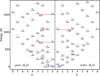 |
Fig. 1 Water energy level diagram for the lower portion of the vibrational ground state. As indicated, para levels are shown to the left and ortho levels are shown to the right. The state energy is given in Kelvin and is shown as a function of quantum number
Kc. Near each level, the quantum numbers |

2 Observations
Observations were made using the Swedish Heterodyne Facility Instrument (SHFI) APEX-3 receiver (Vassilev et al. 2008; Belitsky et al. 2006) between May 8 2013 and May 20 2015. SHFI APEX-3 was a double-side-band (DSB) heterodyne receiver covering the frequency range 385-500 GHz. The rest frequencies of the target lines (Table 1) were covered by two tunings, one centred near 439 GHz and the other at 472.8 GHz. For the latter tuning, the CO 4–3 line emerging from the image band appears in between the two water lines. The two tunings were observed on the same night towards any given target (Table 2) such that the observations are quasi-simultaneous. The high-frequency tuning also includes lines from SO and SiO; see Table 1.
The instantaneous back-end bandwidth for each tuning was 4 GHz, as made up from two partly overlapping 2.5 GHz Fast Fourier Transform Spectrometers (FFTS) of 32 768 channels (Klein et al. 2012). Observations were made in beam-switching mode with an azimuthal throw of 100 arcsec and with a switching frequency of 0.5 Hz to reduce the impact of atmospheric fluctuations.
Weather conditions were always good during our observations. In 2013 the precipitable water vapour column was around 0.3 mm while in 2014 and 2015 it was typically in the range 0.3–0.45 mm. Pointing observations in the CO 4–3 line were made towards the science targets themselves providing the CO line was strong enough; otherwise nearby carbon-rich CSEs were used. The APEX full half-power beam width at 460 GHz is 13 arcsec.
Between March 20 and June 13, 2014, the APEX-3 receiver response to the calibration loads was not linear and for a subset of our observations additional re-calibration factors had to be applied1 to the data. Also, the normal calibration factors for the DSB receiver APEX-3 are those given at the centre of each FFTS 2.5 GHz segment for the signal band. In the APEX-3 frequency band, the atmospheric transmission can vary substantially over our bands. As a result, spectral lines coming from the image band, like CO(4–3) in our case, have to be recalibrated due to the different atmospheric optical depths at signal and image frequencies. This latter recalibration was done for all sources and all epochs. The main beam efficiency for APEX-3 is ηmb = 0.60 and the adopted Jansky-to-Kelvin conversion factor was 48 Jy∕K2. The typical calibration uncertainty is 10–15%.
Observed lines.
3 Results
The CO and water observations are displayed in Figs. 2–12. In addition, blended SO with 29SiO, and SiO serendipitous detections are shown. The CO, SO, and 29SiO observationsare reported in main beam temperature scale. In some cases, a function proportional to  has been fitted to the CO spectrato obtain an estimate of the gas terminal velocity ve. The water and SiO v = 1 observationsare reported in flux density. The visualised thermal line spectra have been resampled to a resolution of 0.5 km s−1 while the maser lines are shown with a velocity resolution of 0.25 km s−1. The detections and their characteristics are reported in Tables A.1–A.11, using a velocity resolution of 0.25 km s−1.
Stellar sample and water maser detections.
 |
Fig. 2 APEX-3 observations towards VX Sgr. The observations of CO, SO, and 29SiO are reported in main beam temperature using a velocity resolution of 0.5 km s−1. Observations of the water lines and SiO v = 1 are reported in flux density and are shown with a spectral resolution of 0.25 km s−1. |
4 Water maser detections
In the discussion that follows, we consider maser lines to be detected (“Y” in Table 2) when peak or integrated emission values exceed 3σ, see Tables A.1–A.11.
There are some caveats to consider when drawing general conclusions from the maser results. Firstly, the masers are time-variable and for the majority of targets we only have information at one or two epochs (with the exception of semi-regular variable R Crt, for which five epochs of data were obtained). In addition, the upper limits in the observations are relatively high, and differ between targets and observation epochs. Nevertheless, with the above cautions we tentatively note the following:
VX Sgr and U Her
These are the highly variable (ΔV > 7.0) longest-period pulsators (P > 400 days). Strong emission from all four lines is detected. The maser at 437 GHz is significantly stronger than those at 439, 471, and 474 GHz.
RR Aql, W Hya, R Hya, RS Vir, R Leo, and R Aql
These are the medium-period pulsators (200 <P < 400 days) with a magnitude variation of ΔV > 4.0. There are a mixture of detections and non-detections towards these targets. When detected, the 437 GHz maser is usually the strongest line. However, for W Hya (lowest visual variation in the group) this is not the case. At the first epoch, detected maser lines have very similar peak strength and at the second epoch the 474 GHz line is the strongest. W Hya generally seems to be different from the other targets in that at both epochs it displays 29SiO v = 0 J = 11−10 emission. At the second epoch, it also displays SiO v = 1 J = 11−10 maser emission.
R Dor, R Crt, and RT Vir
These are the semi-regular variables with periods of less than 200 days and a magnitude variation of ΔV < 2.0. The targets in this category appear to be the least likely to host strong water maser emission at 437, 439, 471, and 474 GHz. R Crt was observed at five epochs with no detections and RT Vir at two epochs with no detections. Towards R Dor, there is a marginal detection of the 471 GHz line only.
5 Water maser radiative transfer modelling
We performed two different types of radiative transfer modelling. The first approach was to run a grid of homogeneous models designed to determine the parameter space in which 437, 439, 471, and 474 GHz maser emission occurs. This approach provides a good indication of the optimum combination of physical conditions needed to yield strong maser emission in the lines. The second approach was to model water maser emission from the CSE of a star with a smooth stellar wind and a range of mass loss rates. This approach provides a good approximation of the conditions in the outer CSE. We performed the smooth wind maser modelling to confirm our interpretation of the grid results and understand the effect of different mass loss rates on maser emission from the outer CSE. In a future study, we intend to explore this model more thoroughly by including line overlaps and to treat the inner envelope more accurately with the inclusion of shocks.
The water maser radiative transfer modelling and the CO modelling (see Appendix B) are based on an Accelerated Lambda Iteration (ALI) code specifically developed for handling the large positive and negative optical depths encountered when studying the water emission from molecular clouds and CSEs. The ALI scheme adopted here is based on the formalism described by Rybicki & Hummer (1991). Also, we include a dust continuum in the radiative transfer following the approach as outlined in Rybicki & Hummer (1992). Although Rybicki & Hummer (1992) also fully describe how to include line overlap in their ALI formalism, we have not enabled this feature in any of our models presented here. This particular ALI code, adapted to spherically symmetric geometry, has been used extensively since the work by Justtanont et al. (2005) and was tested against other radiative transfer codes by Maercker et al. (2008). Normally, the iterative procedure starts with a number of lambda iterations (LIs) to provide a good starting point for subsequent accelerated iterations. This procedure was adopted in the homogeneous models but not for the CSE models (see Sect. 5.2) in which accelerated iterations were employed from the first iteration. Other numerical improvements to the convergence and stability of level population changes over iterations can be invoked if needed. These are Ng-accelerations (Ng 1974) or a simple reduction in the amount of level population change between iterations. As demonstrated by Yates et al. (1997) in their ALI plane-parallel code, one can ensure convergence even in the case of negative optical depths by sufficiently reducing the step-size. Here, we adopt a slightly different strategy, limiting the acceleration for those transitions that show substantial negative optical depths (typically if the optical depth < −1 across a shell). This is implemented in the code by not including parts of a line where the optical depth is below this limit when integrating the averaged approximate lambda operator over angles and frequencies. That is, for those relatively few strongly inverted transitions, we use this modified ALI scheme which would be equal to the standard LI scheme if there were no contributionat all to the averaged approximate lambda operator. This step is performed at every iteration when the ALI scheme is employed in order to improve the numerical stability. Using this strategy, the number of radial points can be lower, but the number of shells should still be large enough to describe the radial behaviour of the physical conditions in CSEs reasonably well.
The radiative transfer modelling is done separately for the ortho and para symmetries of water. For o-water, we can include up to 411 levels and 7597 radiative transitions. The same numbers for p-water are 413 and 7341, respectively.These numbers of levels correspond to an upper energy of about 7200 K and include vibrational levels from both the excited bending mode ν2 and the symmetric stretching mode ν1. For the H2−H2O collisional data we use the coefficients of Faure & Josselin (2008) which are tabulated at 11 kinetic temperatures in the range from 200 K to 5000 K. Linear interpolation of downward rates is used for temperatures in between the tabulated values. If the temperature is below 200 K we scale the downward collisional rates at 200 K with (T/200 K)1/2. All upward collisional rates are subsequently calculated from the downward rates by detailed balance.
5.1 Physical conditions for 437, 439, 471, and 474 GHz water maser emission
We first investigate the physical circumstances in which we obtain maser emission for our 400 GHz target lines. As the homogeneous model cloud, we use a spherical cloud with a radius of R = 1014 cm, a water abundance of  , and an ortho-to-para ratio of three. This high water abundance is close to the maximum possible large-scale water abundance (as limited by the availability of oxygen atoms). By reducing the water abundance, one can increase the cloud radius to obtain essentially the same result. The turbulent velocity is 1 km s−1 and no systematic velocity field is used. Although we adopt constant physical conditions throughout the model cloud we still divide the cloud into 15 concentric shells of equal thickness to allow for radial excitation variations. Optionally, we can include a central source (a black body of a certain luminosity and temperature). The number of frequency points is 17 and the number of angles (over which the radiation field is integrated) is increased from 12 in the innermost shell to 16 for the outermost shell. The mean intensity for all transitions at each radial point includes contribution from the line itself emerging from other parts of the cloud, and thus saturation effects are always included for inverted transitions. Normally, we include a dust component in each shell, with a dust temperature independent of the gas kinetic temperature and a certain gas-to-dust mass ratio (typically Rgd = 100). For the study presented here, a very simple dust model is adopted with a dust opacity that varies with frequency according to ν2 and a mass absorption coefficient of κ250 μm = 10 cm2 g−1. In addition, the model clouds are always exposed to the 2.7 K black body radiation field from the outside.
The ALI code is run over a grid of values. We vary the kinetic temperature, Tkin, from 120 to 5000 K and the H2 density, n(H2), is varied from 106 to 3 × 1010 cm−3. For each setof parameters, we compute a line profile for several different transitions, always adopting a beam size equal to the cloud diameter. Our main aim here is to investigate how strong the 437, 439, 471, and 474 GHz maser emissions can become. To visualise this, we normalise the integrated intensity, Iν, of each line to that of the 557 GHz ortho line (i.e. we compute the base-10 logarithm of Iν ∕I557). The results for the case where Rgd = 100 and Tdust = Tkin without a central source are shown in Fig. 13. Besides our 400 GHz lines we also include the results for the 22 GHz and 183 GHz water lines for comparison. As can be seen, the 439 and 474 GHz lines are weakly masing while the 437 and 471 GHz lines show no masers.
The inclusion of dust has a strong impact on the maser activity (Yates et al. 1997). In Fig. 14, we show the previous model set but this time not including any dust (or central source). If we compare with the results in Fig. 13, we see that the inclusion of dust (with Tdust = Tkin) has a clear quenching effect on the maser action.
Following the results of Yates et al. (1997), in that some masers become stronger when Tdust < Tkin, we ran the models in Fig. 13 but this time with Tdust = Tkin∕2 and 3Tkin∕2. We also ran models with Rgd = 50 and 200 for the case where Tdust = Tkin∕2. These four model runs are displayed in Fig. 15. Allowing for Tdust = Tkin∕2 leads to a remarkable increase of the maser line intensities by several orders of magnitude. Increasing the amount of dust with Rgd = 50 only leads to a moderate increase in the 400 GHz maser line intensity. The 22 GHz maser intensity behaves differently and is strongly dependent on the amount of dust. This is also valid for the 183 GHz maser intensity but to a lesser extent.
The key factor here for strong masers seems to be that the dust temperature is lower than the kinetic temperature. In fact, in the case of our model, setting Tdust ~ Tkin∕3 maximises the maser action. On the other hand, for Tdust≳Tkin the maser action is rather quenched. In our homogeneous models we have not seen any marked deviations from I437 ≲I471≲I474≲I439. For the latter pair of lines, we conclude that although the maximum peak temperature is normally somewhat higher for the 439 GHz line than for the 474 GHz line, the density–temperature region over which masers occur is slightly different in the 474 GHz case than in the 439 GHz case (see Fig. 15). As a result, line ratios of these maser transitions may behave differently depending on the exact nature of any gradients in the physical parameters.
We also tested the effect of the inclusion of a central black body with a radius of r = 0.1 R and black body temperatures up to 4000 K, but only see minor changes to the intensities of the 400 GHz masers.
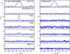 |
Fig. 9 APEX-3 observations towards R Aql. The CO 4–3 features at +20, +30, and +80 km s−1 are due to ISM contamination. |
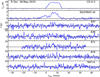 |
Fig. 10 APEX-3 observations towards R Dor. |
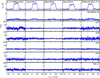 |
Fig. 11 APEX-3 observations towards R Crt. |
5.2 Circumstellar smooth-wind maser modelling
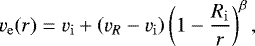
To model the water emission from CSEs we divided our model cloud with radius R into a larger number of shells (typically 60 with logarithmic spacing). Both for ortho and para species, only levels below 4000 K are included. A few test runs with a larger number of shells (120) and higher energy limit (6000 K) resulted in minor changes: less than 5% variation in maser peak intensities for the targeted 400 GHz lines. The innermost radius, Ri, is given by the luminosity and temperature of the star (see Table 2). The kinetic temperature is always set to 33 K at the cloud surface (as the water radius is only 0.6 of the CO radius where Tkin = 20 K) and to the stellar temperature at Ri. The kinetic temperature decline in the shells then follows r−α with α near 1 (0.68 for U Her and 0.83 for W Hya). The H2 density radial dependence is entirely given here via the continuity equation; by an adopted mass loss rate, Ṁ, and a radial gas expansion velocity according to
 (1)
(1)
where vi is the radial gas velocity at Ri and vR is the terminal gas velocity. Following Maercker et al. (2016), here we set vi = 3 km s−1 and use β = 3∕2. As in the homogeneous models, the turbulent velocity width is 1 km s−1.
The water abundance due to photo-dissociation in the interstellar radiation field (cf. Netzer & Knapp 1987; Maercker et al. 2016) can be described by
 (2)
(2)
where X(0) is the water abundance near the centre and re is the e-folding radius describing the relatively sharp decline of water molecules due to photo-dissociation in the outer part of the CSE. Here, as in the previous section, we set X(0) to 5× 10⁻⁴ and re = 0.8 R. Also, we use CSE CO radius R = R1∕2 (see Appendix B and Table B.2) as the outer water radius. For comparison we also include the modelled profiles for re = 0.1R. This latter re is more in line with the water photo-dissociation radius as formulated by Maercker et al. (2016) and based on the work by Netzer & Knapp (1987). We use a relatively large value of X(0) here because we want to explore conditions in which water maser activity is most prone to occur. In our water modelling, we mainly vary the mass loss rate from 3 × 10⁻⁸ to 10−4 M⊙ yr−1 and we adopt the same dust properties as in the previous section, except that we use Rgd= 200 and Tdust(r) = Tkin(r)∕2.
Two model cases were run. The sources selected were U Her and W Hya because they both show 400 GHz masers while having quitedifferent sizes for their CSEs; see Table B.2.
The U Her model results, R = 1.3 × 1016 cm (see Table B.2), are shown in Fig. 16 for different mass loss rates. The model cloud spectra haven been convolved with Gaussian beams appropriate for the APEX telescope. The masers (for 439 and 474 GHz) appear only for mass loss rates around (1−10) × 10−6 M⊙ yr−1. Here the blueshifted peak is stronger than the redshifted peak since much of the redshifted amplification path at approximately + ve is obscured by the central opaque source and the stellar radiation is amplified for approximately − ve (González-Alfonso & Cernicharo 1999). The radius range, in which the radial optical depths in the 439 GHz line are negative, is [0.006 R, 0.081 R] for a mass loss of 3 × 10⁻⁶ M⊙ yr−1 at which the 439 GHz line is the strongest line (having a peak intensity around 250 Jy at the blueshifted peak). For other mass loss rates the 474 GHz transition is the dominant line.
The mass loss rate for U Her determined by the CO modelling is 2.0 × 10⁻⁷ M⊙ yr−1; see Table B.2. No strong 400 GHz masers at ± ve are expected for this massloss rate, even with re = 0.8 R. The expected 474 GHz peak intensity for the non-masing line at Ṁ = 3 × 10⁻⁷ M⊙ yr−1 is around 1 Jy which is below the observed rms level for U Her (see Table A.2).
Figure 17 shows the W Hya model 400 GHz spectra for the same set of mass loss rates as for U Her. The W Hya CSE, at 5 × 1015 cm, is smaller than that of U Her but its mass loss rate, at 3.2 × 10⁻⁷ M⊙ yr−1, is similar to that of U Her. The masers show the same behaviour for W Hya as in the case of our U Her models. For a mass loss rate of 1 × 10⁻⁶ M⊙ yr−1, the 439 GHz maser activity is maximised and the radial range over which the radial optical depths are negative is [0.006 R, 0.11 R].
For our homogeneous models in Sect. 5.1, we find that the peak brightness of the 439 GHz line is usually stronger than that of the 474 GHz line. On the other hand, in the case of the U Her and W Hya models, we see that the 439 GHz line is as bright as the 474 GHz line, albeit only at a specific mass loss rate (3 × 10⁻⁶ M⊙ yr−1 for U Her and 1 × 10⁻⁶ M⊙ yr−1 for W Hya). Nevertheless, the 474 GHz maser activity extends over a larger range of mass loss rates. From the results in Fig. 15 we see that the optimum combination for 439 GHz masers to occur is given by  . If we adopt this kinetic temperature behaviour at each radius of our model cloud we obtain much stronger masers (in all 400 GHz lines). Likewise, if we start with our kinetic temperature relation T0(r/R)α and use the optimum maser relation to determine the H2 density, we obtain essentially the same result.
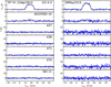 |
Fig. 12 APEX-3 observations towards RT Vir. |
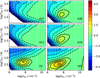 |
Fig. 13 Homogeneous cloud water grid models with Rgd = 100 and Tdust = Tkin and no central source. The white dots indicate the grid points for which models were run. The transition frequency is shown in each panel in gigahertz. The line intensities for each line are described by a base-10 logarithmic contour and colour scale which is normalised to the 557 GHz line intensity (Iν ∕I557). The green area depicts the region where the line in question has a similar strength to the 557 GHz line. The maximum intensity of the 183 GHz line, which occurs around Tkin = 300 K and n(H2) = 3 × 107 cm−3, is about 102 times stronger than the 557 GHz line intensity. |
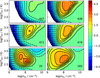 |
Fig. 14 Homogeneous cloud water models without a dust component and no central source. Scales and contours are as in Fig. 13. |
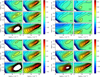 |
Fig. 15 Homogeneous cloud water models for different dust properties. Top left: Rgd = 100 and Tdust = Tkin∕2. Top right: Rgd = 100 and Tdust = 3Tkin∕2. Bottom left: Rgd = 50 and Tdust = Tkin∕2. Bottom right: Rgd = 200 and Tdust = Tkin∕2. Scales and contours are as in Fig. 13. In the 22 GHz maser case, intensity ratios, I22 ∕I557, are sometimes in excess of 105 (central white areas). The strongest 22 GHz maser in these four cases occurs in the bottom left panel for Tkin = 700 K and n(H2) = 1010 cm−3. Here the integrated intensity ratio is about 107. |
6 Discussion
Out of our sample of 11 evolved stars, 7 display one or more of the maser lines studied here at 437, 439, 471, and 474 GHz. We therefore find that these masers are common in CSEs of evolved stars. Moreover, we note our study is only sensitive to masers of peak flux density ≳15 Jy, and so they may be even more common at for example the 1 Jy level. As noted earlier in Sect. 4, we tentatively find that the presence of strong masers in these lines correlates with the variability in the magnitude of the star during the pulsation cycle. This could indicate that shocks are needed to create the pumping conditions for the masers. It is plausible that one must provide a better physical description of the inner part of the CSE, where dust particles form and help accelerate the gas, to understand the appearance of 400 GHz water masers. This is most likely coupled to the pulsation of the central star, and models like those investigated by Bladh et al. (2019) could provide further insight in this area.
One of the more striking observational results is that the 437 GHz maser line is typically by far the strongest. However, this transition is not found to be significantly inverted in the work of Gray et al. (2016), which predicts many other of the common masers. It is also not found to be strongly masing in the current work, despite the fact that the grid of physical conditions covers all those expected for the likely location of the masers (the masers are unlikely to predominantly originate in the outer wind region because the line shapes would then be double-peaked and bracket the stellar velocity). We therefore speculate that some other ingredient must be necessary for the production of strong maser emission in this line. We suggest line overlap may be the cause and therefore we plan to perform a systematic investigation of this in future work. Gray et al. (2016) did include line overlap within the of para and ortho water species separately, but it may be that overlap between the species is also of importance here. One such overlap involves the rotational transitions  (o) and 66,0 −55,1 (p) which are within 3.6 km s−1 of each other around 33.0 μm. Interestingly, this particular line overlap is directly coupled to three of our four 400 GHz maser transitions (see Table 1). Another para and ortho overlap involving the lower 437 GHz level is the
  (p) and 77,0 −66,1 (o) transitions at 28.6 μm. This line overlap corresponds to 0.4 km s−1. We also note that there is an overlap at 6.63 μm of three ro-vibrational transitions within 10.4 km s−1 that are related to the 437 GHz transition. These are the ν2 = 1 to 0 transitions 65,2−66,1 (o), 65,1 −66,0 (p), and 75,3−76,2 (p). We used frequencies listed in the high-resolution transmission molecular absorption database (HITRAN, Gordon et al. 2017) to calculate the line overlap distances. Since the ortho-species is likely to be more abundant than the para-species (3:1 at thermal equilibrium), the line overlap between the species could generally be more important for para lines. However, for individual lines, the exact details of the overlap, such as for example the amount of overlap (including velocity field) and A-coefficients of involved transitions, will be paramount. We note that the velocities of up to > 10 km s−1 required for the overlaps may explain why the 437 GHz maser has not yet been found to be associated with star-forming regions. In any event, a more detailed investigation of possible line overlaps for water may be of importance to better understand the mechanism(s) giving rise to 437 GHz masers.
An interesting feature of these masers is the significance of dust, which was previously indicated by the work of Yates et al. (1997). Figures 13 and 14 indicate that the maser lines in general become stronger when there is no dust, compared with when there is dust present at the same temperature as that of the gas and the maser action is quenched. Figure 15 displays the line intensities for four different dust temperatures, showing that maser emission is strong when the dust temperature is lower than that of the gas temperature. The optimum situation for strong maser emission is when the dust temperature is about one-third of the gas temperature for our homogeneous cloud models. The amount of dust also affects maser activity for the 400 GHz masers, although the impact is smaller than that on the 22 GHz maser; see Fig. 15. Lowering the gas-to-dust ratio from 200 to 50 seems to slightly increase the maser activity for the 439 GHz and 474 GHz maser lines while 437 GHz and 471 GHz maser activity goes in the opposite direction and is slightly diminished.
For water masers at 22 and 183 GHz (Gonzalez-Alfonso et al. 1998), it is known that in objects of relatively low mass loss rate, the maser emission is tangentially beamed from the inner CSE where radial velocity gradients are too high to meet the so-called velocity coherence required for maser amplification. For objects of higher mass loss rate, the physical conditions needed to pump themasers can be found further from the star where the radial velocity gradients are lower. Towards these objects, the maser line shapes are no longer predominantly single peaked at the stellar velocity, but have a double-peaked structure bracketing the stellar velocity at up to the terminal velocity for the object. In some cases, the redshifted emission is obscured by the star, so only the blueshifted peak is observed at a velocity offset from the stellar velocity.
For our sample, all of the observed 400 GHz lines appear to be originating predominantly from the inner CSE (the acceleration zone region), that is, they occur near the velocity centroid of the CO emission. This is quite the opposite to what is indicated bythe smooth wind modelling. The smooth wind modelling indicates that emission can, as at 22 and 183 GHz and perhaps for all water masers, originate from the outer wind; see for example González-Alfonso & Cernicharo (1999). From our U Her and W Hya modelling (assuming the preferable conditions for maser emission: high water abundance of 5 × 10⁻⁴ and Tdust(r) = Tkin(r)∕2), a strong and double-peaked maser profile is achieved for the 437 and 474 GHz lines when the mass loss rate is in the range of about 10−6−10−5 M⊙ yr−1. For a higher mass loss rate, the maser action becomes quenched. With the exception of VX Sgr and possibly R Aql, none of our targets has such a high mass loss rate.
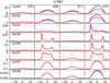 |
Fig. 16 Model water spectra of the 400 GHz lines in the case of U Her. The frequency is shown in the top row spectra in gigahertz. Each row of spectra corresponds to the mass loss rate indicated in the leftmost spectrum. The blue profiles correspond to re = 0.8 R and the red profiles to re = 0.1 R. The vertical scale, in Janskys, is different for each mass loss rate. The horizontal scale is in velocity (km s−1). The strongest maser activity is found for Ṁ = 3 × 10⁻⁶ M⊙ yr−1 and is absent for the highest mass loss rates. The mass loss rate derived from the CO lines is 2 × 10⁻⁷ M⊙ yr−1. |
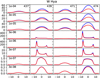 |
Fig. 17 Model water spectra of the 400 GHz lines for W Hya. The layout and scales are as in Fig. 16. The strongest maser activity is found for Ṁ = (1−3) × 10−6 M⊙ yr−1. The mass loss rate derived from the CO lines is 5 × 10⁻⁷ M⊙ yr−1. |
7 Summary and conclusions
We performed observations at the water maser frequencies of 437, 439, 471, and 474 GHz using APEX towards 11 stars. Our findings can be summarised as follows.
-
The masers are common and strong towards Mira variables. We suggest that the masers are either less strong or are highly variable and absent towards semi-regular variables for some part of the stellar pulsation cycle.
-
The line shapes of the observed maser lines are approximately centred at the stellar velocity rather than being double-peaked and bracketing the stellar expansion velocity. This likely indicates that the masers originate predominantly from the wind acceleration zone of the CSEs rather than from the outer wind.
-
The 437 GHz line is typically by far the strongest line in the observations. We cannot reproduce this behaviour with radiative transfer models. In our homogenous models, there is never significant deviation from I437≲I471≲I474≲I439. In our CSE models, the maser activity of the 474 GHz line occurs over a larger range of mass loss rates than the 439 GHz maser activity. Also, no strong maser activity in the 437 and 471 GHz transitions is seen in our CSE models.
-
We speculate that line overlap both within and between the ortho and para water species may need to be incorporated to reproduce observations of the 437 GHz line. Purely rotational overlaps around 30 μm and ro-vibrational overlaps at 6.63 μm may be the key.
-
We find that dust temperature plays an important role in the production of strong masers in these lines. The optimum dust temperature for strong maser emission is around Tkin∕3 for homogeneous models. It is clear that the gas and dust interplay is important for these masers and therefore detailed characteristics of the dust properties and the heating and cooling processes of the gas may be important to gain a better understanding of the 400 GHz water masers.
-
Our smooth wind CSE modelling confirms that it is possible to achieve double-peaked water maser emission for the 439 and 474 GHz lines as is the case for the 22 and 183 GHz water masers. However, it requires a high water abundance in the region where the expansion velocity is near the terminal velocity; a mass loss rate in the range of about 10−6−10−5 M⊙ yr−1 seems tobe needed for this to happen. We cannot reproduce the observed line shapes in the smooth wind modelling, namely single-peaked maser lines at the stellar velocity. We suggest that this is another indicator that the masers originate from the inner envelopes of our targets and require the presence of strong shocks.
Acknowledgements
We thank the OSO observing teams, aided by the APEX staff, for performing these observations, which were part of the APEX Swedish queue. We are also very grateful to Hans Olofsson for discussions and comments on an earlier version of this paper. We acknowledge with thanks the variable star observations from the AAVSO International Database contributed by observers worldwide and used in this research.
Appendix A Observational results
In this appendix, we present the observational measurements towards each target. The measurements and stellar phases at the different epochs have been entered in Tables A.1–A.11. If the 437 GHz line is the strongest line in any source and epoch, its tabulated intensity value is set using a boldfaced font. All peak and channel rms values relate to a velocity resolution of 0.25 km s−1.
VX Sgr results.
U Her results.
RR Aql results.
W Hya results.
R Hya results.
RS Vir results.
R Leo results.
R Aql results.
R Dor results.
R Crt results. It was not possible to determine the stellar phases for these observations.
RT Vir results.
Appendix B Mass loss rate determination
We also performed CO line modelling using the CO(4–3) data in this paper, as well as additional CO line data listed in Table B.1 to determine the stellar mass loss rates. We use the same ALI code as used for our water modelling in Sect. 5. For CO and H2 collisions weuse the coefficients calculated by Yang et al. (2010). We adopt a density radial model as given by the mass loss rate and a constant expansion velocity as determined from the width of our observed CO 4–3 lines, and a kinetic temperature profile as outlined in Sect. 5.2. The CO abundance used is 5 × 10⁻⁴ near the centre and is half that at r = R1∕2 and declines exponentially out to the cloud radius at about R = R1∕2∕0.6 where the envelope is truncated. Here we construct a grid by varying mass loss rate Ṁ and CO radius R1∕2 and display our fitting results by means of a reduced  value calculated from observed line intensities and modelled ones using appropriate beam sizes. For each source, between three and seven integrated line intensities are used (see Table B.1). In the case where the CO 4–3 line was observed at different epochs, the integrated intensity obtained at the date with smallest uncertainty was used. The grid results for our targeted stars are displayed in Figs. B.1–B.3. In each of the figures, a line is shown corresponding to the relation between the mass loss rate and the CO photo-dissociation radius (and expansion velocity) found by Mamon et al. (1988). The modelling results are summarised in Table B.2.
In all of the figures, the region where the models are in closest agreement with the observations (dark blue areas) show a similar shape for all our sources. Reasonable fits can often occur for a range of mass loss rates, but only when adopting the corresponding size. The fitting is done by comparing integrated line intensities and not by fitting the shape of the line profiles. The latter would have been preferable but we do not have access to the spectral information of most other CO lines than those presented here. Typically there is a difference in line profiles over the range of acceptable combinations of Ṁ and R1∕2. For larger mass loss rates and smaller R1∕2, the CO 4–3 profile is parabolic while for lower mass loss rates the shape starts to become flat-topped and even double-peaked. This is a resolution effect in that for Ṁ and large R1∕2, the CSE emission is more likely to be resolved by the adopted beam size (Olofsson et al. 1982). The Mamon et al. (1988) relation tends to agree better with the results of the stars with lower mass loss rates (Ṁ ≲10−6 M⊙ yr−1). The best-fit results of Ṁ and R1∕2 are shown in Table B.2, along with best-fit values corresponding to the Mamon et al. (1988) size–mass loss rate dependence (the position along the line in Figs. B.1–B.3 where it crosses the dark blue area). For most of our sources (8 out of 11), the CO size determined by the free fit is smaller than that determined by the Mamon et al. (1988) relation. This is in agreement with the recent work by Saberi et al. (2019) who suggest that the CO size due to photodissociation (and including shielding effects) is smaller that the size reported by Mamon et al. (1988). The determined mass loss rates are in reasonable agreement with earlier estimates (e.g. De Beck et al. 2010).
CO line intensities, in K km s−1, used in the modelling.
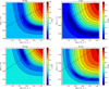 |
Fig. B.1 Grid of mass loss rate modelling for VX Sgr, U Her, RR Aql, and W Hya. The contours represent the base-10 logarithm of the reduced |

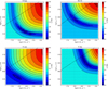 |
Fig. B.2 Grid of mass loss rate modelling for R Hya, RS Vir, R Leo, and R Aql. Scales are as in Fig. B.1. |
CO modelling results.
References
- Bains, I., Cohen, R. J., Louridas, A., et al. 2003, MNRAS, 342, 8 [NASA ADS] [CrossRef] [Google Scholar]
- Baudry, A., Humphreys, E. M. L., Herpin, F., et al. 2018, A&A, 609, A25 [NASA ADS] [CrossRef] [EDP Sciences] [Google Scholar]
- Belitsky, V., Lapkin, I., Monje, R., et al. 2006, SPIE Conf. Ser., 6275, 62750G [Google Scholar]
- Bladh, S., Liljegren, S., Höfner, S., Aringer, B., & Marigo, P. 2019, A&A, 626, A100 [NASA ADS] [CrossRef] [EDP Sciences] [Google Scholar]
- Chen, X., Shen, Z.-Q., & Xu, Y. 2007, Chin. J. Astron. Astrophys., 7, 531 [Google Scholar]
- De Beck, E., Decin, L., de Koter, A., et al. 2010, A&A, 523, A18 [NASA ADS] [CrossRef] [EDP Sciences] [Google Scholar]
- Faure, A., & Josselin, E. 2008, A&A, 492, 257 [NASA ADS] [CrossRef] [EDP Sciences] [Google Scholar]
- González-Alfonso, E., & Cernicharo, J. 1999, ApJ, 525, 845 [NASA ADS] [CrossRef] [Google Scholar]
- Gonzalez-Alfonso, E., Cernicharo, J., Alcolea, J., & Orlandi, M. A. 1998, A&A, 334, 1016 [NASA ADS] [Google Scholar]
- Gordon, I. E., Rothman, L. S., Hill, C., et al. 2017, J. Quant. Spectr. Rad. Transf., 203, 3 [Google Scholar]
- Gray, M. D., Baudry, A., Richards, A. M. S., et al. 2016, MNRAS, 456, 374 [NASA ADS] [CrossRef] [Google Scholar]
- Groenewegen, M. A. T., Baas, F., Blommaert, J. A. D. L., et al. 1999, A&AS, 140, 197 [NASA ADS] [CrossRef] [EDP Sciences] [Google Scholar]
- Güsten, R., Nyman, L. Å., Schilke, P., et al. 2006, A&A, 454, L13 [NASA ADS] [CrossRef] [EDP Sciences] [Google Scholar]
- Haniff, C. A., Scholz, M., & Tuthill, P. G. 1995, MNRAS, 276, 640 [NASA ADS] [CrossRef] [Google Scholar]
- Humphreys, E. M. L., Greenhill, L. J., Reid, M. J., et al. 2005, ApJ, 634, L133 [NASA ADS] [CrossRef] [Google Scholar]
- Humphreys, E. M. L., Immer, K., Gray, M. D., et al. 2017, A&A, 603, A77 [NASA ADS] [CrossRef] [EDP Sciences] [Google Scholar]
- Hunter, T. R., Young, K. H., Christensen, R. D., & Gurwell, M. A. 2007, IAU Symp., 242, 481 [NASA ADS] [CrossRef] [Google Scholar]
- Josselin, E., Loup, C., Omont, A., et al. 1998, A&AS, 129, 45 [NASA ADS] [CrossRef] [EDP Sciences] [Google Scholar]
- Justtanont, K., Bergman, P., Larsson, B., et al. 2005, A&A, 439, 627 [NASA ADS] [CrossRef] [EDP Sciences] [Google Scholar]
- Kerschbaum, F., & Olofsson, H. 1999, A&AS, 138, 299 [NASA ADS] [CrossRef] [EDP Sciences] [Google Scholar]
- Klein, B., Hochgürtel, S., Krämer, I., et al. 2012, A&A, 542, L3 [NASA ADS] [CrossRef] [EDP Sciences] [Google Scholar]
- Knapp, G. R., Pourbaix, D., Platais, I., & Jorissen, A. 2003, A&A, 403, 993 [NASA ADS] [CrossRef] [EDP Sciences] [Google Scholar]
- Maercker, M., Schöier, F. L., Olofsson, H., Bergman, P., & Ramstedt, S. 2008, A&A, 479, 779 [NASA ADS] [CrossRef] [EDP Sciences] [Google Scholar]
- Maercker, M., Danilovich, T., Olofsson, H., et al. 2016, A&A, 591, A44 [Google Scholar]
- Mamon, G. A., Glassgold, A. E., & Huggins, P. J. 1988, ApJ, 328, 797 [NASA ADS] [CrossRef] [Google Scholar]
- Melnick, G. J., Menten, K. M., Phillips, T. G., & Hunter, T. 1993, ApJ, 416, L37 [NASA ADS] [CrossRef] [Google Scholar]
- Menten, K. M., Lundgren, A., Belloche, A., Thorwirth, S., & Reid, M. J. 2008, A&A, 477, 185 [NASA ADS] [CrossRef] [EDP Sciences] [Google Scholar]
- Menten, K. M., & Melnick, G. J. 1991, ApJ, 377, 647 [NASA ADS] [CrossRef] [Google Scholar]
- Menten, K. M., & Young, K. 1995, ApJ, 450, L67 [NASA ADS] [CrossRef] [Google Scholar]
- Netzer, N., & Knapp, G. R. 1987, ApJ, 323, 734 [NASA ADS] [CrossRef] [Google Scholar]
- Ng, K. C. 1974, J. Chem. Phys., 61, 2680 [NASA ADS] [CrossRef] [Google Scholar]
- Olofsson, H., Johansson, L. E. B., Hjalmarson, A., & Nguyen-Quang-Rieu. 1982, A&A, 107, 128 [NASA ADS] [Google Scholar]
- Olofsson, H., Lindqvist, M., Nyman, L. A., & Winnberg, A. 1998, A&A, 329, 1059 [NASA ADS] [Google Scholar]
- Richards, A. M. S., Etoka, S., Gray, M. D., et al. 2012, A&A, 546, A16 [NASA ADS] [CrossRef] [EDP Sciences] [Google Scholar]
- Richards, A. M. S., Impellizzeri, C. M. V., Humphreys, E. M., et al. 2014, A&A, 572, L9 [Google Scholar]
- Rybicki, G. B., & Hummer, D. G. 1991, A&A, 245, 171 [NASA ADS] [Google Scholar]
- Rybicki, G. B., & Hummer, D. G. 1992, A&A, 262, 209 [NASA ADS] [Google Scholar]
- Saberi, M., Vlemmings, W. H. T., & De Beck, E. 2019, A&A, 625, A81 [NASA ADS] [CrossRef] [EDP Sciences] [Google Scholar]
- Teyssier, D., Hernandez, R., Bujarrabal, V., Yoshida, H., & Phillips, T. G. 2006, A&A, 450, 167 [NASA ADS] [CrossRef] [EDP Sciences] [Google Scholar]
- van Leeuwen, F. 2007, A&A, 474, 653 [NASA ADS] [CrossRef] [EDP Sciences] [Google Scholar]
- Vassilev, V., Meledin, D., Lapkin, I., et al. 2008, A&A, 490, 1157 [NASA ADS] [CrossRef] [EDP Sciences] [Google Scholar]
- Vlemmings, W. H. T., & van Langevelde, H. J. 2007, A&A, 472, 547 [NASA ADS] [CrossRef] [EDP Sciences] [Google Scholar]
- Whitelock, P. A., Feast, M. W., & Van Leeuwen, F. 2008, MNRAS, 386, 313 [NASA ADS] [CrossRef] [Google Scholar]
- Yang, B., Stancil, P. C., Balakrishnan, N., & Forrey, R. C. 2010, ApJ, 718, 1062 [NASA ADS] [CrossRef] [Google Scholar]
- Yates, J. A., & Cohen, R. J. 1996, MNRAS, 278, 655 [NASA ADS] [CrossRef] [Google Scholar]
- Yates, J. A., Cohen, R. J., & Hills, R. E. 1995, MNRAS, 273, 529 [NASA ADS] [CrossRef] [Google Scholar]
- Yates, J. A., Field, D., & Gray, M. D. 1997, MNRAS, 285, 303 [NASA ADS] [Google Scholar]
- Young, K. 1995, ApJ, 445, 872 [NASA ADS] [CrossRef] [Google Scholar]
- Zhang, B., Zheng, X., Reid, M. J., et al. 2017, ApJ, 849, 99 [NASA ADS] [CrossRef] [Google Scholar]
All Tables
R Crt results. It was not possible to determine the stellar phases for these observations.
All Figures
|
Fig. 1 Water energy level diagram for the lower portion of the vibrational ground state. As indicated, para levels are shown to the left and ortho levels are shown to the right. The state energy is given in Kelvin and is shown as a function of quantum number
Kc. Near each level, the quantum numbers |
| In the text | |
|
Fig. 2 APEX-3 observations towards VX Sgr. The observations of CO, SO, and 29SiO are reported in main beam temperature using a velocity resolution of 0.5 km s−1. Observations of the water lines and SiO v = 1 are reported in flux density and are shown with a spectral resolution of 0.25 km s−1. |
| In the text | |
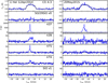 |
Fig. 3 As for Fig. 2 but for U Her. |
| In the text | |
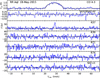 |
Fig. 4 As for Fig. 2 but for RR Aql. |
| In the text | |
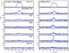 |
Fig. 5 As for Fig. 2 but for W Hya. |
| In the text | |
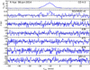 |
Fig. 6 As for Fig. 2 but for R Hya. |
| In the text | |
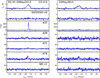 |
Fig. 7 As for Fig. 2 but for RS Vir. |
| In the text | |
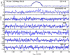 |
Fig. 8 As for Fig. 2 but for R Leo. |
| In the text | |
|
Fig. 9 APEX-3 observations towards R Aql. The CO 4–3 features at +20, +30, and +80 km s−1 are due to ISM contamination. |
| In the text | |
|
Fig. 10 APEX-3 observations towards R Dor. |
| In the text | |
|
Fig. 11 APEX-3 observations towards R Crt. |
| In the text | |
|
Fig. 12 APEX-3 observations towards RT Vir. |
| In the text | |
|
Fig. 13 Homogeneous cloud water grid models with Rgd = 100 and Tdust = Tkin and no central source. The white dots indicate the grid points for which models were run. The transition frequency is shown in each panel in gigahertz. The line intensities for each line are described by a base-10 logarithmic contour and colour scale which is normalised to the 557 GHz line intensity (Iν ∕I557). The green area depicts the region where the line in question has a similar strength to the 557 GHz line. The maximum intensity of the 183 GHz line, which occurs around Tkin = 300 K and n(H2) = 3 × 107 cm−3, is about 102 times stronger than the 557 GHz line intensity. |
| In the text | |
|
Fig. 14 Homogeneous cloud water models without a dust component and no central source. Scales and contours are as in Fig. 13. |
| In the text | |
|
Fig. 15 Homogeneous cloud water models for different dust properties. Top left: Rgd = 100 and Tdust = Tkin∕2. Top right: Rgd = 100 and Tdust = 3Tkin∕2. Bottom left: Rgd = 50 and Tdust = Tkin∕2. Bottom right: Rgd = 200 and Tdust = Tkin∕2. Scales and contours are as in Fig. 13. In the 22 GHz maser case, intensity ratios, I22 ∕I557, are sometimes in excess of 105 (central white areas). The strongest 22 GHz maser in these four cases occurs in the bottom left panel for Tkin = 700 K and n(H2) = 1010 cm−3. Here the integrated intensity ratio is about 107. |
| In the text | |
|
Fig. 16 Model water spectra of the 400 GHz lines in the case of U Her. The frequency is shown in the top row spectra in gigahertz. Each row of spectra corresponds to the mass loss rate indicated in the leftmost spectrum. The blue profiles correspond to re = 0.8 R and the red profiles to re = 0.1 R. The vertical scale, in Janskys, is different for each mass loss rate. The horizontal scale is in velocity (km s−1). The strongest maser activity is found for Ṁ = 3 × 10⁻⁶ M⊙ yr−1 and is absent for the highest mass loss rates. The mass loss rate derived from the CO lines is 2 × 10⁻⁷ M⊙ yr−1. |
| In the text | |
|
Fig. 17 Model water spectra of the 400 GHz lines for W Hya. The layout and scales are as in Fig. 16. The strongest maser activity is found for Ṁ = (1−3) × 10−6 M⊙ yr−1. The mass loss rate derived from the CO lines is 5 × 10⁻⁷ M⊙ yr−1. |
| In the text | |
|
Fig. B.1 Grid of mass loss rate modelling for VX Sgr, U Her, RR Aql, and W Hya. The contours represent the base-10 logarithm of the reduced |
| In the text | |
|
Fig. B.2 Grid of mass loss rate modelling for R Hya, RS Vir, R Leo, and R Aql. Scales are as in Fig. B.1. |
| In the text | |
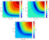 |
Fig. B.3 Grid of mass loss rate modelling for R Dor, R Crt, and RT Vir. Scales are as in Fig. B.1. |
| In the text | |
Current usage metrics show cumulative count of Article Views (full-text article views including HTML views, PDF and ePub downloads, according to the available data) and Abstracts Views on Vision4Press platform.
Data correspond to usage on the plateform after 2015. The current usage metrics is available 48-96 hours after online publication and is updated daily on week days.
Initial download of the metrics may take a while.