| Issue |
A&A
Volume 629, September 2019
|
|
|---|---|---|
| Article Number | A146 | |
| Number of page(s) | 19 | |
| Section | Interstellar and circumstellar matter | |
| DOI | https://doi.org/10.1051/0004-6361/201834717 | |
| Published online | 18 September 2019 | |
IRC + 10°216 mass loss properties through the study of λ3 mm emission
Large spatial scale distribution of SiO, SiS, and CS★
1
Department of Space, Earth and Environment, Chalmers University of Technology, Onsala Space Observatory,
439 92
Onsala,
Sweden
e-mail: This email address is being protected from spambots. You need JavaScript enabled to view it.
2
Instituto de Física Fundamental (IFF–CSIC),
Serrano 123,
Madrid,
CP 28006,
Spain
3
Institut de Radioastronomie Millimétrique,
300 Rue de la Piscine,
38406
Saint-Martin d’Hères,
France
Received:
26
November
2018
Accepted:
6
July
2019
Abstract
Low-mass evolved stars are major contributors to interstellar medium enrichment as a consequence of the intense mass-loss process these stars experience at the end of their lives. The study of the gas in the envelopes surrounding asymptotic giant branch (AGB) stars through observations in the millimetre wavelength range provides information about the history and nature of these molecular factories. Here we present ALMA observations at subarsecond resolution, complemented with IRAM-30 m data, of several lines of SiO, SiS, and CS towards the best-studied AGB circumstellar envelope, IRC + 10°216. We aim to characterise their spatial distribution and determine their fractional abundances mainly through radiative transfer and chemical modelling. The three species display extended emission with several enhanced emission shells. CS displays the most extended distribution reaching distances up to approximately 20′′. SiS and SiO emission have similar sizes of approximately 11′′, but SiS emission is slightly more compact. We have estimated fractional abundances relative to H2, which on average are equal to f(SiO) ~10−7, f(SiS) ~10−6, and f(CS) ~10−6 up to the photo-dissociation region. The observations and analysis presented here show evidence that the circumstellar material displays clear deviations from an homogeneous spherical wind, with clumps and low density shells that may allow UV photons from the interstellar medium (ISM) to penetrate deep into the envelope, shifting the photo-dissociation radius inwards. Our chemical model predicts photo-dissociation radii compatible with those derived from the observations, although it is unable to predict abundance variations from the starting radius of the calculations (~10 R*), which may reflect the simplicity of the model. We conclude that the spatial distribution of the gas proves the episodic and variable nature of the mass loss mechanism of IRC + 10°216, on timescales of hundreds of years.
Key words: stars: AGB and post-AGB / circumstellar matter / stars: individual: IRC+10216
The reduced datacubes are only available at the CDS via anonymous ftp to cdsarc.u-strasbg.fr (130.79.128.5) or via http://cdsarc.u-strasbg.fr/viz-bin/cat/J/A+A/629/A146
© ESO 2019
1 Introduction
Circumstellar envelopes (CSEs) around low to intermediate mass stars are some of the most active sites of molecular and dust formation in the Galaxy. They have a major impact on synthesising material and enriching the interstellar medium (ISM) for subsequent galactic evolution (see Habing & Olofsson 2003, for a general review on asymptotic giant branch (AGB) stars). This has stimulated a large number of studies aimed at searching for and characterising the molecular emission of AGB stars since the opening of the (sub-)millimetre wavelength window (e.g. Solomon et al. 1971; Turner 1971; Olofsson et al. 1982; Cernicharo et al. 1986). But as in other different domains of the electromagnetic spectrum, the limited spatial resolution achieved by single-dish radio telescopes prevented astronomers from drawing solid conclusions about relevant questions such as AGB wind and mass-loss nature or about the formation processes of dust particles and molecules (e.g. Cernicharo et al. 1989; Velilla Prieto et al. 2017). Here we provide new observational constraints to the molecular emission of IRC + 10°216 impinging on the nature of its mass-loss history and photo-dissociation processes, thanks to the spatial resolution and excellent sensitivity provided by the Atacama Large Millimetre/submillimetre Array (ALMA).
After decades of research and intensive observational efforts, IRC + 10°216 is still probably one of the most attractive objects for molecular study in the context of AGB CSEs. CW Leo is the central star of the object, classified as the 216th object in the +10° declination band of the infrared catalogue (Neugebauer & Leighton 1969). It is located at ~120 pc away from us (Groenewegen et al. 2012) and its molecular envelope has been formed as a result of intense mass loss (2–4 × 10⁻⁵ M⊙ yr−1, Guélin et al. 2018,and references therein) of this C-rich Mira variable (period ~630 days, Menten et al. 2012). The systemic velocity of the source with respect to the local standard of rest (LSR), v*, is −26.5 ± 0.3 km s−1 and the terminal expansion velocity of the circumstellar gas (v∞) is 14.5 ± 0.2 km s−1 (Cernicharo et al. 2000).
In terms of molecular content, it is the richest AGB CSE with a total of ~80 different species detected (along with many other of their isotopologues), representing almost half of the total molecules found in the interstellar and circumstellar medium. IRC + 10°216 is also a primetarget for studies of carbon dust formation in AGBs (Martin & Rogers 1987; Groenewegen 1997; Cernicharo et al. 2000, 2017). Several diatomic molecules are efficiently formed in the atmosphere of the star, such as CO, CS, or SiS, where the chemistry is controlled mainly by thermodynamical equilibrium (TE), as well as by shocks due to the pulsation of the star (Agúndez & Cernicharo 2006; Fonfría et al. 2008; Agúndez et al. 2012; Velilla Prieto et al. 2015, and references therein). In particular, SiS and CS are predicted to be very abundant in the inner layers of C-rich AGB CSEs by TE models (with average values of ~10−6 relative to H2, Agúndez et al. 2012), and even higher in the case of SiS if the effect of periodic shocks are considered in the models (Cherchneff 2012). The case of SiO is particularly interesting, since most oxygen in C-rich stars is thought to be locked into the stable molecule CO while it is detected with significant abundances in the inner region of IRC + 10°216 (Agúndez et al. 2012; Fonfría et al. 2014). TE models predict almost negligible abundances for SiO in the atmospheres of these C-stars, while higher abundances (up to ~10−5) are predicted at distances of ~5 R* (Agúndez et al. 2012). Shock-induced chemistry due to the pulsation of the star may also play a role in the abundance of SiO and other molecules in the dust-formation region (Cherchneff 2012). Other scenarios may also contribute to the production of O-bearing species in the CSEs of C-rich stars and vice versa, such as an enhanced photo-induced chemistry due to clumpiness, as explored by Agúndez et al. (2010), or Van de Sande & Millar (2019), or additionally if the extra source of UV radiation is a hotter binary companion. SiS and SiO, as refractory molecules for the temperatures found in the region between 1 and 20 R*, should have an important role in the condensation and growth of dust grains (see e.g. Gail & Sedlmayr 1986, 2013; Gail et al. 2013, and references therein).
From previous observational studies of rotational lines, including highly excited vibrational states, it is concluded that CS and SiS have typical abundances of ~3 × 10⁻⁶ in the innermost layers of IRC + 10°216 decreasing down to ~10−6 at 10–20 R* and then disappearing from the gas phase at ~600 R* in the case of SiS and at ~1000 R* for CS (Agúndez et al. 2012). These authors also derived a constant SiO abundance of ~10−7 from the inner layers up to distances of ~500 R*. The spatial distribution of these three molecules has also been traced with interferometric observations, showing roughly compact distributions extended up to ~10–12′′, equivalent to ~520–630 R* for SiS, ~350–520 R* for SiO, and ~850–1000 R* for CS (Lucas et al. 1992, 1995; Bieging & Tafalla 1993; Patel et al. 2011). These observations were obtained with a spatial resolution of ~3–5′′ with the Institut de Radioastronomie Millimétrique (IRAM) Plateau de Bure Interferometer (PdBI), the Berkeley-Illinois-Maryland Array (BIMA), and the Submillimetre Array (SMA). It is worth noting that due to the lack of short-spacing observations the sizes listed beforemay be strictly considered as lower limits, although this should have a limited impact in the case of compact distributions (see the discussion for the case of SiS in Bieging & Tafalla 1993). Large-scale flux is provided by short-space observations, thus, single-dish observations must be considered if the aim is to study the complete molecular emission of an extended object.
In this paper we present our latest results from the study of several emission lines of SiS, SiO, and CS isotopologues detected in the 3 mm wavelength spectrum of IRC + 10°216 using ALMA at subarsecond spatial resolution. The observations and reduction methods are described in Sect. 2. The observational results are presented in Sect. 3. In Sect. 4 we present radiative transfer models aimed at deriving the radial abundance distribution of the three molecules studied. In Sect. 5 we present an updated analysis of the chemistry of the studied species. A consolidating discussion of the results is presented in Sect. 6. Finally, in Sect. 7 we present the conclusions of this work.
2 Observations
The data presented here belong to observations completed with the ALMA and the IRAM-30 m telescopes. We carried out ALMA observations in band 3, corresponding to a λ 3 mm spectral line survey of IRC + 10°216 covering the frequency range ~84.0–115.5 GHz during Cycle 2. The total frequency coverage was achieved by using five different spectral setups with an effective spectral resolution of 0.488 MHz (channel spacing 0.244 MHz). We used the C34-7 and C34-2 configurations (extended and compact, respectively). The extended configuration encompassed baselines up to ~1600 m, resulting in synthesised beam sizes as small as ~0.″6. The compact configuration provided baselines as low as 13 m and up to 390 m, resulting into maximum recoverable scales in the range of ~23′′ up to ~32′′ depending on the frequency. The observations were taken during several runs on December 4, 2014, and on June 29, July 4, 5, and 19, 2015. We did an initial calibration of the ALMA data with the Common Astronomy Software Applications (CASA, McMullin et al. 2007) by using the scripts provided by the ALMA team. To calibrate the gain (for phases and amplitudes) J0854+2006 or J0854+201 were observed. The quasar J1058+0133 was consistently used for the bandpass calibration. In half of the tracks, observations of Ganymede or Callisto were performed to calibrate absolute amplitudes, as their Butler-JPL-Horizons-2012 models were integrated in CASA and used as reference. For the other tracks, fluxes stored in the ALMA database for other calibrators (J0854+201, J1058+015, and J0854+2006) were used. From the differences obtained at the end for the fluxes of different calibrators and dates, we estimate an accuracy in the flux calibration better than 15%. Finally, for every track the standard phase calibration was improved by self-calibrating with the very compact source continuum emission, by using the Grenoble Image and Line Data Analysis System (GILDAS) software package. A single pointing was done towards the source position, with coordinates J2000.0 RA = 9h47m57.s446 and Dec = 13°16′43.″86 according to the position of the λ 1 mm continuum emission peak (Cernicharo et al. 2013). A complete description of these ALMA observations will be presented elsewhere (Cernicharo, in prep.).
IRAM-30 m on-the-fly (OTF) observations were carried out on June 7–11, 2015, in order to recover the flux filtered out by ALMA. With this purpose, we obtained OTF maps of 96′′ × 96′′ in the frequency range of ~80–116 GHz, with an average nominal sensitivity of 5 mK and a velocity resolution of 1.5 km s−1. These maps were observed in position-switching mode with a position throw of ~240′′ off-source. Standard procedures of calibration, including pointing and focus on strong and nearby sources, were followed regularly during the observing runs.
Final data cubes were produced by merging the ALMA and IRAM-30 m data after continuum subtraction. This was done by using the UVSHORT task in the GILDAS software package that uses the pseudo-visibility technique to produce visibilities from single-dish maps, merge them to interferometric visibilities, and use adapted deconvolution algorithms to properly image the emission detected at several spatial scales (see Pety & Rodríguez-Fernández 2010, and references therein for more details). The relative amplitude calibration between ALMA and 30 m OTF data was particularly checked in the uv-plane, in the interface between the different visibilities, before image synthesis.
Two final data cubes were generated for every spectral window. The first was produced with a lower spatial resolution by using the natural visibility weights. In this case, we obtain optimum point-source sensitivity with moderated spatial resolution. A second data cube was obtained by using a robustness factor of 0.5 during the deconvolution process to adapt the visibility weights in order to reach a higher angular resolution, though with a slight decrease in sensitivity. In both cases, the Steer-Dewdney-Ito algorithm (SDI, Steer et al. 1984) was used during the cleaning process, given that Högbom (1974) can introduce artificial clumpiness when generating images of objects that have extended emission. In all the cases a comparison was made between the different cleaning methods to ensure the consistency and quality of our results. A list of the emission lines observed and the corresponding synthesised beams is given in Table 1.
Summary of parameters for observed lines.
3 Results
In this section we present the observational results derived from the analysis of the brightness distribution and the moment 0 maps for the detected lines of the main isotopologues of SiO, SiS, and CS, which are shown in Figs. 1–4, and their corresponding position-velocity (PV) diagrams shown in Fig. 5. We present spectra of the four emission lines towards the position of the star extracted from the central pixel of the merged (ALMA plus 30 m OTF) observations in Fig. 6. Azimuthal averages of the brightness distribution of the ALMA-30 m merged data of the channel corresponding to the systemic velocity of IRC + 10°216 are presented inFig. 7. We also present the OTF spectra of the four emission lines towards the position of the star in Fig. 8. Maps of the brightness distribution and PV diagrams corresponding to the rest of the detected isotopologues are presented in Appendices A and B.
3.1 SiO
We detected emission from the J = 2–1 lines of SiO, 29SiO, and 30SiO. The spatial distribution of these emission lines is compatible with a roughly spherical CSE, which extends up to approximately 11′′ or equivalently ~600 R* (R* = 0.″019 ± 0.003, Ridgway & Keady 1988). This CSE is radially expanding, as seen in Fig. 5, with a v∞ consistent with previous measurements (14.5 km s−1, see Sect. 1).
SiO emission displays an inhomogeneus spatial distribution, with arcs and clumps (see Fig. 1). The bulk of the emission arising from the most compact and inner shells, that is r ≲ 5′′, seems to be elongated along the north-east-south-west (NE-SW) direction (Fonfría et al. 2014), with the brightness distribution peak towards the position of the continuum peak. From the position of the star, the brightness starts to decrease outwards along the radial direction, (as can be seen in the brightness distribution of the emission at the channel corresponding to v − v* = 0 km s−1) decreasing by a factor of two at r2 ~0.″86 (~45 R*) and by a factor of e at re ~3′′ (~160 R*). Irregular enhancements of the emission along the radial direction are clearly seen in Fig. 7. The most noticeable enhancements or bumps appear at approximately 1.″8 (~90 R*) and 7.″8 (~410 R*), and some structures evoke the aspect of circular arms, such as the two structures seen at r ~8′′ between PA ~ [90–180°] and PA ~ [270–360°], and the two at r ~10′′ between PA ~ [135–180°] and PA ~ [315–360°] (see Fig. 1).
Self-absorption and/or absorption of the continuum emission arising from the inner layers of the CSE is observed at negative velocities for the gas located in front of the star. This can be noticed in the different brightness temperatures at the most extreme blue and redshifted velocities of the line spectrum towards the position of the star in Fig. 6. From this spectrum, we also observe that emission at the horns, and in particular the redshifted horn, is more prominent than emission at the line center. This difference, a priori, could be a consequence of the higher opacity of the gas expanding at the terminal velocity.
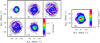 |
Fig. 1 SiO J = 2–1 maps extracted from high spatial-resolution data cube. Left: flux density (Sν) maps at different offset velocities with respect to the systemic velocity of the source (v* ~ −26.5 km s−1, Cernicharo et al. 2000) in LSR scale. The central velocity offset of each channel is shown at the bottom-left corner of each panel in kilometres per second. The width of each velocity channel is approximately 1 km s−1. The coordinates are given as offsets from the source position in arcseconds (see Sect. 2). The size and orientation of the synthetic beam are shown at the top-left corner inside the first panel. The contours shown in black correspond to 5σ, 2, 10, 50, and 90% of the peak flux density (see Table 1). Right: moment zero map. The contours shown correspond to 10, 25, 50, 75, and 90% of the peak emission (see Table 1). |
3.2 SiS
We detectedemission of the J = 5–4 and 6–5 lines of SiS, 29SiS, 30SiS, and Si34S. The spatial distribution of emission of these lines is similar to that of SiO.
SiS emission is also characterised by an inhomogeneus spatial distribution, displaying clumpy structures and arcs (see Figs. 2 and 3). The bulk of the emission arising from the most compact and inner shells (r ≲ 5′′) is essentially spherical. The emission peak at the systemic velocity coincides with the position of the continuum peak. The brightness distribution observed in this velocity channel displays spatial inhomogeneities that are more clearly seen for the J = 6–5 emission line (Fig. 3). As for SiO, the flux density falls outwards along the radial direction from the position of the star (see Fig. 7). However, the azimuthal average of the flux density of the SiS J = 5–4 line displays a decrease of a factor of two at r2 ~1.″1 (~60 R*) and of a factor e at re ~ 1.″7 (~90 R*), while that of the J = 6–5 line shows r2 ~ 0.″8 (~40 R*) and re ~ 0.″9 (~50 R*). The analysisof the azimuthal average of the flux density of both SiS lines leads to the identification of several density enhancements located at approximately 4.″3 (~225 R*), 5.″9 (~310 R*), and 8.″1 (~425 R*) for the SiS J = 5–4 line, and at 2.″8 (~150 R*), 4.″7 (~245 R*), and 7.″9 (~420 R*) in the case of the J = 6–5 line. The brightness distribution of the J = 6–5 emission line at the channel corresponding to the systemic velocity of the source also shows the presence of bright arcs appearing at r ~ 8′′ between PA ~ [270–360°] and also at r ~ 5′′ between PA ~ [20–180°] (see Fig. 3).
The SiS line profiles shown in Fig. 6 display strong differences between them. Emission at velocities close to the systemic velocity of the source is similar for the two lines, J = 6–5 and J = 5–4. However, the intense horns seen at terminal velocities in the SiS J = 5–4 line profile are not visible in the J = 6–5 line profile. This anti-correlation between the line wing emission of the two lines was previously reported by Carlström et al. (1990). The redshifted peak of the SiS J = 5–4 line is approximately ten times stronger than its counterpart in the J = 6–5 line. The difference in the intensity of the two horns of the SiS J = 5–4, and also between the blue and redshifted wings of the J = 6–5 line, may beinterpreted as self-absorption and/or absorption of the continuum emission emitted by the inner layers of the CSE, as was the case for SiO (see Sect. 3.1 and Fig. 6).
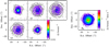 |
Fig. 4 As in Fig. 1, but for CS J = 2–1. We note that there is a change of the spatial scale compared to that of Figs. 1–3. |
3.3 CS
We detect emission of the J = 2–1 lines of CS, 13CS, C34S, and C33S. The emission of the main isotopologue (Figs. 4 and 5) is compatible with a radially expanding spherical CSE, which extends up to approximately 20′′ (~1000 R*) from the star, that is much more extended than SiO and SiS emission. From the PV diagram the v∞ is compatible with previous estimates for the source.
CS emission is remarkably clumpy with sub-structures arranged in the form of concentric shells or circular arcs, as can be seen in Fig. 4. The bulk of the emission arising from the innermost shells (r ≲ 5′′) is also circular, as is the case for SiS. The emission peak at the systemic velocity is on the continuum source. For this velocity channel, we observe a high degree of clumpiness for distances r >10′′ (≳520 R*) with several thin shells clearly evident in the azimuthal average of the flux density (see Fig. 7). In particular, seven density enhancements were identified through the analysis of the brightness distribution at the systemic velocity, peaking at 2.″9 (150 ~ R*), 4.″7 (250 ~ R*), 6.″0 (315 ~R*), 8.″2 (430 ~R*), 10.″7 (565 ~R*), 14.″2 (750 ~R*), and 15.″8 (830 ~R*) from the central star. The radius where the flux density has decreased by a factor of two is r2 ~ 0.″6 (~30 R*) and of a factor of e at re ~ 0.″8 (~40 R*).
From the spectrum towards the stellar position in Fig. 6, we observe, as for SiO, that emission at the horns is more prominent than emission at the line center. Particularly, the most extreme redshifted emission is ≳1.5 times more intense than emission at any other velocity component, possibly as a consequence of the higher opacity of the gas expanding at the terminal velocity. As for SiO and SiS, CS-blueshifted emission presents an emission deficit, which could be due to self-absorption and/or absorption of the continuum emission emitted by the inner layers of the CSE (see Sect. 3.1 and Fig. 6).
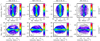 |
Fig. 5 Position–velocity (PV) diagrams of detected lines of SiO, SiS, and CS main isotopologues. The contours shown in black correspond to 5σ, 2, 10, 50, and 90% of the peak emission (see Table 1 for details). Top: PV diagram of the flux density is shown corresponding to a plane with a declination offset (see Sect. 2) equal to zero. Bottom: PV diagram of the flux density is shown corresponding to a plane with a right ascension offset (see Sect. 2) equal to zero. |
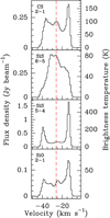 |
Fig. 6 Spectrum of the four lines towards the central pixel (0.″1 × 0.″1). This coincides with the position of the star (see Sect. 2) obtained from the ALMA-OTF merged observations (see also Table 1 for the basic parameters of the lines). The dashed red line represents the systemic velocity of the source (v* ~ −26.5 km s−1, Cernicharo et al. 2000)relative to the LSR. |
4 Radiative transfer modelling
In this section we present the method and results for the radiative transfer modelling of the SiO J = 2–1, SiS J = 5–4 and 6–5, and CS J = 2–1 emission. We aim to determine the radial abundance distribution of these molecules in the CSE of IRC + 10°216.
We carried out radiative transfer models using the code that is described in detail in Agúndez et al. (2012). The code computes the radiation field and the level populations of a certain molecule by solving the statistical equilibrium equations coupled to the radiation transfer problem following an iterative classical process under the large velocity gradient (LVG) approximation (Sobolev 1960; Castor 1970; Goldreich & Kwan 1974). The emergent line profiles are calculated by ray-tracing across the envelope.
The CSE is modelled as a spherical circumstellar gas and dust envelope expanding at a constant velocity. It is divided according to a spherical shell gridding of 100 shells evenly spaced on a logarithmic scale for the radius. The physical model of the CSE is essentially an updated revision of the models in Agúndez et al. (2012) and Cernicharo et al. (2013). The updated parameters are the kinetic temperature radial profile and the mass-loss rate, which have been recently estimated in Guélin et al. (2018). The fixed parameters of the model are presented in Table 2. The code uses as input the radial abundance profiles that are presented in Fig. 9.
The collisional rates taken into account to solve the statistical equilibrium equations consider only collisions with H2. Mass correction was applied when necessary. The rates used are the following: (i) for SiO we used the values from Dayou & Balança (2006) and Balança & Dayou (2017), including ro(tational)-vibrational transitions up to v = 1, and for the lowest 50 rotational levels; (ii) for SiS we used the values from Kłos & Lique (2008) and Toboła et al. (2008) (see also Velilla Prieto et al. 2015), including ro-vibrational transitions up to v = 2, and for the lowest 70 rotational levels; (iii) for CS we used the values from Denis-Alpizar et al. (2018), including ro-vibrational transitions up to v = 1 and for the lowest 30 rotational levels. A higher number of vibrational and rotational levels were considered during the modelling but we report only levels that are up to those values from which significant differences do not arise by increasing the number of levels. Specific tests of the impact that infrared (IR) pumping could have in our models are described in the following section.
Our purpose is to derive the radial abundance profiles that reproduce the azimuthal averages observed, at least up to a level where model predictions are on average compatible with the observations. A fine-tuning of the model in order to fit each detail seen in the azimuthal averages would require a significant increase of the gridding points of the model, not in line with the spatial resolution achieved (poorer than ~0.″6 or ~30 R*), which would also lead to a significant increase of the computing time. Additionally, it can be argued that a perfect fitting could be achieved by modifying the density, the input abundances, and the excitation conditions as a function of radius in different combinations. Such a degeneracy can lead to misinterpreting the results, moreover, if we consider that chemistry is an additional factor playing a major role. Therefore, we will give comments on the general aspects seen in the models while keeping in mind this degeneracy, and leaving the physical interpretation for the discussion in Sect. 6.
The results from the radiative transfer modelling can be seen in Fig. 7, where they are compared with the azimuthal averages, and in Fig. 8, where they are compared with the spectra towards the position of the star as observed with the IRAM-30 m telescope. The half-power beam width (HPBW) of the 30 m telescope as a function of the frequency (ν) can be calculated as: HPBW[′′] ~2460/ν[GHz]1.
The fit to the azimuthal averages of the brightness distribution of the channel corresponding to the systemic velocity of the source is reasonably well achieved by using the radial abundance profiles presented in Fig. 9. For a radially expanding envelope at constant velocity, the emission in this channel is representative of the gas approximately distributed over the plane of the sky, and whose movement is contained within this plane since its velocity component parallel to the line of sight is equal to zero when referenced to the systemic velocity of the source.
From the observations and the radiative transfer models, the first molecule to disappear from the gas phase is SiS (at ~600 R*), then SiO (at ~700–800 R*), and significantly farther, CS (at ~1000 R*). These values are consistent with those reported in previous studies, where the authors reported sharp cutoffs in the radial distribution at ~500–750 R* (for SiS and SiO) and ~900–1000 R* (Bieging & Tafalla 1993; Agúndez et al. 2012). The fractional abundances of SiO and CS seem to have a mild decrease in the intermediate CSE (between ~100 and 300 R*) compared to their abundances in the innermost CSE. For SiO, we derive a fractional abundance of ~10−7, which is in good agreement with the values reported by Agúndez et al. (2012). Several studies of SiO emission have reported higher fractional abundances in the innermost CSE of IRC + 10°216 complemented by the analysis of IR ro-vibrational lines (Keady & Ridgway 1993; Schöier et al. 2006). However, Fonfría et al. (2014) reported a lower abundance of an order of magnitude (~10−8) very close to the star (r < 5 R*) based on theanalysis of the SiO J = 6–5 emission asobserved with high-angular resolution (~0.″25) with the Combined Array for Research in Millimetre-wave Astronomy (CARMA). In the case of CS, we derive an average fractional abundance of ~10−6 in the innermost CSE, decreasing down to ~5 × 10⁻⁷ between ~100 and 300 R*, and then keeping this value in the outermost CSE. The abundance profile derived in the current work is in good agreement with that derived by Agúndez et al. (2012), who also detected an abundance decline in the intermediate envelope. However, our abundance close to the star is a factor of two higher than theirs. We note that these authors considered the first 50 rotational levels within the vibrational states v = 0–3, while we have considered only the first 30 rotational levels in v = 0–1. For SiS, we find an average abundance of ~1–2 × 10⁻⁶ in the region up to ~70–100 R*, mildly decreasing from that point by less than a factor of two up to the cutoff radius (~600 R*). Previous studies of SiS emission towards IRC + 10°216 reported radial abundance distributions compatible with our results (Bieging & Tafalla 1993; Agúndez et al. 2012; Fonfría et al. 2015).
In order to reproduce some of the emission enhancement shells seen in the azimuthal average of the four lines, the fractional abundance has to be increased locally at certain radii from the star. As we have noted before, this can also be achieved by increasing the total gas density without a significant increase of the fractional abundance of the given molecule. At this point, we cannot conclude which of the two scenarios is more realistic until our results are also tested against chemical predictions (Sect. 5). We also want to note that our study is based solely on the analysis of just a single line in the cases of SiO and CS, and two lines in the case of SiS, which prevents us from drawing more solid conclusions on the physical conditions of the CSE and the spatial distribution of the three species. Dedicated subarsecond resolution observations of different rotational lines, probing different excitation conditions, would be required to derive a more realistic model.
Following the fitting procedure of the radial brightness distribution of the line emission representing the gas expanding in the plane of the sky, we tested the accuracy of the model to predict the observed spectrum of the emission lines towards IRC + 10°216 as observed with the IRAM-30 m antenna. The results obtained from this model are presented in Fig. 8. In this case, the gas producing the spectrum corresponds to the gas distributed along the line of sight within the telescope beam. For a radially expanding spherical CSE with the velocity gradient given in Table 2, the gas directly behind the star should be moving away from us, thus, it is seen in the red part of the spectrum, while the gas in front of the star should be moving towards us, and is therefore seen in the blue part of the spectrum. The synthetic spectra of the SiO J = 2–1, SiS J = 5–4, and CS J = 2–1 reproduce (on average) the intensity of the observed lines at central velocities (v < v∞) using the same radial abundance profile as the one we used for the azimuthal averages. In the case of the SiS J = 6–5 line, the synthetic spectrum shows on average adifference of ~20% in the intensity compared to the observed line at central velocities (v < v∞). At terminal velocities, the differences between the observed and synthetic line profiles are more noticeable.
There isa clear difference between the amount of gas probed by the azimuthal average and the amount of gas probed by the 30 m spectrum. In the latter case, the column density of the gas is much higher, which could explain the differences observed between the two cases. Moreover, since all the gas located between the dust condensation region (~20 R*) and the outermost parts of the CSE is expanding at the terminal expansion velocity along the line of sight, most of this gas emission will lie either at the most extreme red or blue velocities in the spectra towards the position of the star. This means that in this case the spatial resolution is significantly hampered, which also explains up to a certain degree the discrepancies seen in the horns of the lines. Likewise, Bieging & Tafalla (1993) reported difficulties when simultaneously fitting the SiS J = 6–5 radial average profile and the line-of-sight spectrum convolved to the beam of a single-dish telescope with a single abundance profile. Nevertheless, we want to recall that our model is, on average and within uncertainties, satisfactory.
We tested the impact that IR pumping has on the computed intensities in our model. Through this mechanism, the population of rotational levels may deviate from what they would have in the absence of the IR radiation emitted by the star and the dust. Moreover, considering the variable nature of AGB stellar emission, this effect iscoupled to the stellar phase, although, this may have a limited impact on optically thick, low J lines (Cernicharo et al. 2014). In our model we eliminated all sources of continuum radiation, that is the star and the dust, to test this scenario. In the case of the azimuthal average of the brightness distribution of the ALMA-30 m channel map at the velocity equal to the systemic velocity of the source, moderate effects are observed. In the case of SiO, the predicted emission is overestimated by ≲15% in the region between ~100 and 300 R* with respect to the model including sources of IR radiation. In the outermost layers (≳400 R*) the predicted emission is understimated by ≲10%. For CS, the predicted emission of the non-IR scenario is overestimated by ≲10% between ~100 and 300 R*. For SiS, the predicted emission would be ≲20% overestimated from ~100 R* up to the cutoff radius.
We also compared the synthetic spectra obtained from our non-IR model with the observed spectra towards IRC + 10°216 with the IRAM-30 m telescope (see Fig. 8). In terms of average intensity, predicted emission for CS is very similar to that of the scenario where sources of IR radiation are included. However, SiO and SiS synthetic lines produced with the non-IR model are overestimated by a factor of ~1.3.
According to our calculations, the excitation conditions for the four transitions are dominated by collisions in the innermost region of the CSE (≲10 R*). From that point, the excitation temperatures increase above the kinetic temperature and then change to sub-thermal for SiO (at ~250 R*), CS (at ~300 R*), and SiS (at ~600 R*). In the case that IR pumping is not considered, the four transitions become sub-thermal at approximately the same distances except for the SiS transitions, which change to sub-thermal at much closer distances to the star (~200 R*). In terms of opacities, our models predict moderate to high opacities throughout the envelope for the four lines analysed.
The case of the excitation of the two SiS transitions, J = 5–4 and 6–5, is particularly interesting, moreover considering the significant differences between the two line profiles in Fig. 6. Our model does not include line overlaps from other abundant species at IR wavelengths, and we limited the calculations to the lowest 70 rotational levels in the vibrational levels v = 0, 1, and 2. Therefore, we cannot assert to what extent the IR line overlaps, nor if the variability of IR stellar light contributes to the excitation of the SiS lines analysed here. However, the line profiles shown in Fig. 6 suggest that the J = 5 level is involved in a particular excitation mechanism that makes J = 5–4 emission at terminal velocities considerably intense, while it is suppressed at the same velocities for the J = 6–5 line. The most plausible explanation for this scenario is maser emission of the J = 5–4 line, probably as a consequence of an IR line overlap as we discuss below.
SiS excitation has been investigated by other authors in the context of the observational study of SiS emission towards IRC + 10°216 (Olofsson et al. 1982; Sahai et al. 1984; Carlström et al. 1990; Bieging & Tafalla 1993; Fonfría Expósito et al. 2006; Fonfría et al. 2018, and references therein). Olofsson et al. (1982) reported observations of the SiS J = 5–4 line with the Onsala-20 m telescope (HPBW ~ 42′′), showing a double-peaked U-shaped profile similar to that seen in Fig. 8. Sahai et al. (1984) observed SiS J = 6–5 emission with the Number Two 10.4 m telescope of the Owens Valley Radio Observatory (OVRO) with a HPBW of ~64′′ and the J = 5–4 emission with the 14 m telescope of the Five College Radio Astronomy Observatory (FCRAO) with a HPBW of ~58′′. From the analysis of the data, Sahai et al. (1984) found that a population inversion occurred for the J = 5–4 transition inthe inner regions of the CSE, due to IR pumping. Sahai et al. (1984) argued that the horns shown in the double-peaked J = 5–4 profile reported by Olofsson et al. (1982), contrary to the rounded profiles that Sahai et al. (1984) reported for the rest of the SiS lines they analysed, was a consequence of weak maser emission observed at maximum stellar phase with the smallest beam among all the observations reported so far at that time. Sahai et al. (1984) also investigated the impact of IR line overlaps on the excitation of SiS that could overexcite the J = 5–4 line, in particular due to the overlap of HCN and C2 H2 with SiS ro-vibrational lines. This line overlapping scenario was also discussed by Bieging & Tafalla (1993), but they found no obvious lines of HCN or C2 H2 overlapping SiS lines that could have a significant impact on the population of low J SiS levels. Carlström et al. (1990) carried out time monitoring of the SiS J = 4–3, 5–4, and 6–5 emission towards IRC + 10°216 with the 20 m telescope in Onsala. They reported that there was correlation between the IR flux and the line shape of the J = 5–4 and 6–5 lines, with the relative intensity of the J = 6–5 line decreasing at stellar maximum, while that of the J = 5–4 line increased at the same stellar phase. However, they did not find correlation for the J = 4–3 line. This would indicate that the population of the J = 5 level varies in phase with the IR light curve. Fonfría Expósito et al. (2006) reported the first detection of high J maser emission and they proposed that this is produced due to line-overlapping between SiS ro-vibrational lines and mid-IR lines of C2 H2 and HCN. Fonfría et al. (2018) reported observations of several SiS lines towards IRC + 10°216, including a time monitoring of the J = 5–4 and 6–5 lines with the IRAM-30 m telescope. Fonfría et al. (2018) showed that the SiS J = 5–4 line displays narrow peaks at high expansion velocities, which vary strongly with the pulsation phase, while the J = 6–5 line shows no intense peaks with a nearly constant profile over the stellar period. The occurrence of these varying peaks in the J = 5–4 line and their lack in the J = 6–5 line leads these authors to conclude that the peaks are masers in nature.
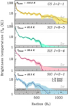 |
Fig. 7 Azimuthal average of brightness distribution of four main isotopologue lines detected of CS (yellow line), SiS (green and red lines), and SiO (blue line). The flux density has been converted to brightness temperature, and the verticalscale is shown in logarithmic scale to improve the visualisation of the plot. The uncertainty intervals (3σ) are also shown in each curve with similar colours. The spatial scale is shown in units of the stellar radius and we also included an additional axis showing the angular scale in the bottom box. The equivalence between both scales is 1 R* ≃ 0.″019 (Ridgway & Keady 1988). On each box, the 5σ-level detection limit is shown in grey. We also indicate the maximum value of the brightness temperature for each distribution, which in all cases corresponds to the central pixel. We marked the levels in which the temperature decreased by half and by a factor of e of its maximum value. The results from the radiative transfer models (see Sect. 4) are shown as dashed black lines in each box. |
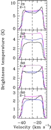 |
Fig. 8 Spectrum of four lines (black histogram) towards star position as observed with IRAM-30 m telescope. The HPBW for the different frequencies is 20.″3 for SiO J = 2–1, 27.″1 for SiS J = 5–4, 22.″6 for SiS J = 6–5, and 25.″1 for CS J = 2–1. The coloured curves represent different synthetic spectra created with our radiative transfer code by using different input radialabundance profiles (see Sect. 4). The blue curves represent the model with which we used the radial abundance profiles shown in Fig. 9 (solid lines in that figure) as input, that is, the best fit profiles to the azimuthal average of the brightness distribution of the emission at the systemic velocity of the source from the ALMA and OTF-30 m merged data. The curves in magenta represent the model with which we used the same input abundance profile but without including any source of continuum radiation in the model, in order to evaluate the impact that IR radiative pumping, produced by the star and the dust, may have in the models. |
Stellar and circumstellar parameters of IRC + 10°216.
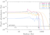 |
Fig. 9 Radial abundance profiles (solid lines) used as input to model azimuthal averages in Fig. 7. The spatial scale is shown in units of the stellar radius and we also included an additional axis showing the angular scale. The equivalence between both scales is 1 R* ≃ 0.″019 ± 0.″003 (Ridgway & Keady 1988). The different radial profiles are created by using Gaussian components but due to conversion from logarithmic radial sampling the profiles display some abrupt changes. We note thatwe have used two different input abundance profiles for SiS, one for each of the lines (J = 5–4 and J = 6–5), aimed at obtaining two independent fits. Both profiles are very similar, and the true and single radial distribution of SiS may be between both profiles. The results from the chemical models described in Sect. 5 are represented by dashed lines of the same colours, except for the SiS line where both magenta and green colours are used. The fractional abundance value is relative to H2. |
Abundances of parent species in chemical model.
5 Chemistry
In this section we present the chemical model we created aimed at testing the observational and radiative transfer results. The model considers a spherical CSE expanding isotropically in the radial direction at constant velocity (equal to v∞) from an initial radius equal to 2 × 1014 cm. Several molecules are used as input for the model, in particular, the parent species listed in Table 3, which are abundant species formed in the innermost layers of the CSE that will determine the subsequent chemistry. The abundances taken for these species are presented in Table 3, which are the values used in Agúndez et al. (2017) after updating the abundances of CS, SiO, and SiS according to our results from the radiative transfer analysis. The chemical network encompasses about 8000 gas-phase, photo-induced, and cosmic-ray reactions, with rate constants taken from the literature and from the UMIST and KIDA databases (McElroy et al. 2013; Wakelam et al. 2015). We assume that the CSE is externally illuminated by the local UV radiation field (Draine 1978). The adopted cosmic-ray ionisation rate of H2 is 1.2 × 10⁻¹⁷ s−1 (Agúndez & Cernicharo 2006). In this work we have adopted a NH /Av value that is 1.5 times lower than the classical value determined for the local ISM (1.87 × 10⁻²¹ cm−2 mag−1, Bohlin et al. 1978). This assumption has been made on the basis of reproducing the interferometer observations of the region where photochemistry occurs (Agúndez et al. 2017, and references therein). Particularly for the three species analysed in this work, we updated two important reactions in the chemistry of SiS according to Zanchet et al. (2018), which are the destruction of SiS with atomic oxygen and the reaction between Si and SO. For the photo-dissociation rates of the studied species we took the values from Pattillo et al. (2018) for CS and from Heays et al. (2017) for SiO. In the case of SiS, there are no estimates of its photo-dissociation rate, thus as an educated guess, we assumed the same value than that of SiO.
The predictions from the chemical model are presented in Fig. 9. The most extended distribution is that of CS, while SiO and SiS abundances fall at similar distances from the star given that we use the same photo-dissociation rate for both molecules. These predictions are qualitatively similar to the observations and the results from the radiative transfer analysis (see Figs. 7 and 9), in terms of the order of the abundance fall-off of the three species. There are relatively small discrepancies in the values of the distance where the abundances of these molecules start to decrease as predicted by the chemical models. In particular, these predictions are on average below a factor of 1.5, being the fall-off distances of the chemical models larger than the observational measurements. As we discuss below, these discrepancies emerge mainly from the simplicity of the chemical model, while the calibration uncertainties and the choice of a robust weighting factor of 0.5 in the imaging process (Sect. 2) have only a limited impact.
The chemical model fails in reproducing the observed high-density shells, with the three species essentially keeping frozen-out abundances until they are photo-dissociated at the outer CSE. It can be argued that the simplicity of the model is probably the main factor responsible for the inconsistencies found between the observations and the chemical models. First, the interaction between the gas and the dust particles is not considered, which has an important impact in the depletion of the gas from the dust condensation region outwards, as well as in other chemical processes throughout the whole CSE. There is also an important source of uncertainty in the choice of the UV field and the NH /Av factor. This ratio has been fixed to be a factor of 1.5 lower than the value by Bohlin et al. (1978), in order to reproduce the results obtained for other molecules such as the carbon chains presented in Agúndezet al. (2017). Higher values of the UV field illuminating the CSE or lower values of the NH /Av ratio than those considered in the models would shift the photo-dissociation radius of the three species to inner regions of the CSE. As we discuss in Sect. 6, this latter consideration could also describe the evolution of mass loss from the star.
There is also another important source of uncertainty, which is the adopted value for the photo-dissociation rate of SiS, which was assumed to be equal to that of SiO. In the case of the abundance fall-off distance of SiO compared to that of CS, the observational results are consistent with the adopted values for the photo-dissociation rates (1.6 × 10⁻⁹ exp(−2.66 Av) and 3.7 × 10⁻¹⁰ exp(−2.32 Av) in s−1 for SiO and CS, respectively; Heays et al. 2017; Pattillo et al. 2018) predicting that SiO should photo-dissociate closer to the star than CS. If the observed fall-off distances respond to a pure photo-dissociation process, then the observations may support that the photo-dissociation rate of SiS should be a bit higher than that of SiO. This observational constraint should be considered in future research aiming to derive accurate SiS photo-dissociation rates.
6 Discussion
The brightness distribution of the different lines we have analysed display important characteristics, such as the arcs and shells seen or the differences in their extension. For this difference we provide an interpretation based primarily on our radiative transfer and chemical modelling results.
6.1 Arcs and shells: episodic and isotropic mass loss?
As noted in Sect. 2, the spatial distribution of the four lines here studied present deviations from how an homogeneous spherical wind should appear. Different arcs and shells are seen in the brightness distributions shown in Figs. 1–4, which could be a consequence of different physico-chemical factors. The azimuthal average of the four brightness distributions at the systemic velocity channel (see Fig. 7) also display several brightness enhanced shells. Someof these shells appear at almost equal distances for the four lines studied, in particular, one is clearly seen at ~8.″0 (~420 R*), and others are seen in some of the azimuthal averages at ~2.″8 (~150 R*), 6.″0 (~315 R*), and 10.″6 (~560 R*). These brightness enhanced shells may seem not exactly coincidental when comparing the four lines displaying small radial shifts that could be due to non-strict circularity of the shells and also possible excitation or optical thickness effects. For the shells appearing at ~420 R*, ruling out excitation effects after the radiative transfer analysis, two different interpretations may be given: it is either a chemical effect or the effect of an enhancement of the gas density in a shell.
The chemistry in this region is mainly driven by gas-phase chemistry, photo-induced chemistry due to UV interstellar radiation field, cosmic-ray interaction, and gas-dust interaction. Our models, which do not take into account gas-dust chemistry, do not predict a particular enhancement in this region. The lack of a detailed model including surface chemistry in dust grains prevents us from assessing the importance that a chemical effect may have in the formation of a chemical enhancement at ~420 R*. However, there is no observational evidence for a critical physical process occurring at this distance modifying the subsequent chemistry, for example a significant increase of the temperature that may enhance thermal desorption from the dust grains. Therefore, it is reasonable to suppose that the gas-dust interaction should behave in a similar way in the region where the shells appear than immediately near inter-shell regions. The second and most likely scenario would be an enhancement of the gas and dust density, maybe as a consequence of an enhanced mass-loss event in the past. Considering an average expansion velocity of the gas equal to v∞ and the distance to the star, the kinematical age for a shell located at ~420 R* would be ~365 yr.
Episodic mass loss from central stars in the AGB phase is known to occur for several C-stars (Olofsson et al. 1996), including IRC + 10°216 (Mauron & Huggins 1999, 2000; Cernicharo et al. 2015). Mauron & Huggins (1999) reported the presence of dust arcs and shells that might be tracing over-dense regions. These authors also discussed the spatial coincidence of dust and gas shells and arcs occurring at distances of r ~10′′, 15′′ and 20′′ (see Fig. 10), with a clear double-ring structure to the north-west of the star. We compared the structures seen in our observations with those traced by dust as seen in the visible scattered light (Mauron & Huggins 1999; Leão et al. 2006) and by other molecules such as CO (Guélin et al. 2018), and the species C2 H, C4 H, C6 H, CN, C3 N, HC3N, and HC5N (Agúndez et al. 2017).
The time lapse between the observations in Mauron & Huggins (1999) and ours is about 16.5 yr, which would account for a ~0.″4 radial shift due to the expansion of the circumstellar material at a constant velocity equal to v∞. Ruling out this small shift, the distribution of the dust shells reported by Mauron & Huggins (1999) is remarkably coincident with that of the gas astraced by the lines reported in our work (see Fig. 10). Several shell structures seen in CS emission at r ~ 15′′ and 20′′ to the north-west, and at r ~ 15′′ and 20′′ to the east clearly match with the shells traced by the dust. The same occurs for SiO emission at distances r ≲ 10′′, where several structures of gas and dust are spatially coincident. The same spatial correlation is seen for the outermost shells of CS, CN, and C3 N emission (Fig. 10). These structures were also seen as spatially coherent in more recent observations of CO emission and other carbon-chains listed before (Agúndez et al. 2017; Guélin et al. 2018). Therefore, the existence of over-dense shells of gas and dust surrounding IRC + 10°216 seems to be the most plausible explanation to the brightness enhanced shells seen in the brightness distributions of SiO, SiS and CS.
Additionally, the presence of a binary companion to IRC + 10°216 has been proposed in previous works (Guélin et al. 1993; Cernicharo et al. 2015). This could result in enhanced episodes of mass loss motivated by the orbital motion of the system when passing through the periastron, as discussed by these authors. The effect of a binary companion would also cause anisotropies and inhomogeneities in the spatial distribution of the dust and the gas. Other authors have also pointed out the possible importance of the action of different instabilities leading to the formation of incomplete dust arcs and clumps (Woitke 2006).
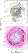 |
Fig. 10 Top: comparison between the gas spatial distribution of the J = 2–1 CS and SiO emission in orange and blue contours, respectively, and the dust distribution reported in Mauron & Huggins (1999) as seen in V +B, where the dark arcs and shells trace the location of the dust (background image in black and white colour scale). The small crosses in the image are also from Mauron & Huggins (1999), and represent the emission peaks of other molecular tracers, namely CN, HNC, and HC3 N reported in Lucas et al. (1995) and Lucas & Guélin (1999). Bottom: same contours representing J = 2–1 CS and SiO emission, with J = 2–1 CS contours in red (changed to improve the visualisation) and J = 2–1 SiO in blue, plotted over C3N N = 10–9 (black contours) and CN N = 1–0 (background image in pink colour scale) as reported by Agúndez et al. (2017). We note that the spatial scale between both figures is different. |
6.2 Emission and photo-dissociation size
The size of the molecular envelope associated with an AGB star depends on the resilience that molecules have against dissociation, which in the case of the outermost layers of the CSE is driven by photo-dissociation by UV photons from the ISM. The results from our work indicate that the observed sizes are slightly smaller compared to the predictions from our chemical model but within uncertainties. Beyond all the simplifications made in the model, which have been commented on in Sect. 5, there is also a physical explanation to the incompatibilities that emerged from the analysis. The photo-dissociation radius would shift inwards in the case that the envelope is less dense than that of the model and also if it has a clumpy structure, or if the UV field is more intense than the value we have adopted (see Sect. 5). To our knowledge, there is no evidence that would suggest that IRC + 10°216 is immersed in a region with a UV field stronger than the average UV interstellar radiation field (Mauron et al. 2003).
Following our discussion in the previous section, all the results would be consistent with episodic mass loss from IRC + 10°216 together with a clumpy structure. According to this scenario, UV photons from the ISM could penetrate deeper in the envelope. This will activate photo-induced processes at distances closer to the star than those expected with an homogeneous CSE, that is a CSE created with a constant mass-loss rate. Periods of low mass-loss activity followed by enhanced episodes would explain the inconsistencies described in Sect. 5, where we considered a constant mass-loss rate. According to the radial abundance profiles presented in Fig. 9, brightness enhanced shells are fitted by enhancing the fractional abundance by a factor ~2–3. Without a complete chemical model that includes gas-dust interaction we cannot affirm to what extent the chemistry contributes to this effect, or even if any chemical contribution is made at all.
7 Conclusions
The observations and analyses we have presented pose strong evidences of a variable mass-loss process acting on IRC + 10°216 with timescales of hundreds of years. In particular, several shells or at least partial shells are seen in the maps obtained with ALMA and the IRAM-30 m telescope (Figs. 1–4) as well as in the azimuthal average of the emission from the velocity channel equal to the systemic velocity of the object (Fig. 7). Several episodes of enhanced mass loss may have occurred to create these dense shells.
We derived the radial profiles of the fractional abundances of SiO, SiS, and CS, which present oscillations that probably reflect the episodic mass-loss of the star. On average, the fractional abundances estimated are f(SiO) ~10−7, f(SiS) ~10−6 and f(CS) ~10−6. With these results from the radiative transfer analysis, we have created a standard chemical model based on gas-phase, photo-induced, and cosmic-ray induced processes. As parent molecules, the three species analysed keep roughly constant abundances within the intermediate CSE until they are photo-dissociated in the more external layers of the envelope. Our model is able to predict a photo-dissociation radii spatial sequence that is consistent with the observationsand the radiative transfer analysis. This means that SiS is photo-dissociated closer to the star; SiO photo-dissociates slightly farther away but very close to SiS; and CS, which presents the most extended distribution, photo-dissociates much farther away from the star. However, the chemical model predicts fall-off distances ~1.5 times larger than those derived from the observations and radiative transfer analysis, and does not predict oscillations in the chemical abundances of the three species in the intermediate envelope, which is probably a consequence of the simplicity of the physical and chemical model. The local departures from the average fractional abundances have to be considered carefully when making a detailed, spatial-scale analysis, until a complete chemical model that includes surface chemistry is considered.
Further research is required in order to understand the processes that lead to the formation of the different shells and clumps observed in the molecular gas of IRC + 10°216. From the observational point of view, high-angular resolution observations with ALMA aiming to a resolution equivalent to ≲5 R* would be necessary to resolve the innermost regions of the CSE. From the theoretical side, future efforts should be directed to improve the chemical networks available by adding gas-dust interaction.
Acknowledgements
We want to thank the referee, J. Bieging, for his careful revision of the manuscript which substantially helped improving the quality of this study. Our team acknowledges the support given by ERC through the grant ERC-2013-Syg-610 256 “NANOCOSMOS”, the Spanish MINECO through the grants AYA2012-32 032 and AYA2016-75 066-C2-1-P and the CONSOLIDER-Ingenio program “ASTROMOL” CSD 2009-00038. L.V.P. acknowledges support from the Swedish Research Council and the ERC consolidator grant 614 264. This work is based on observations carried out under projects numbers 014-13 and 055-15 with the IRAM-30 m telescope. IRAM is supported by INSU/CNRS (France), MPG (Germany) and IGN (Spain). This paper makes use of the following ALMA data: ADS/JAO.ALMA#2013.1.00432.S. ALMA is a partnership of ESO (representing its member states), NSF (USA) and NINS (Japan), together with NRC (Canada) and NSC and ASIAA (Taiwan), in cooperation with the Republic of Chile. The Joint ALMA Observatory is operated by ESO, AUI/NRAO and NAOJ. This research has made use of NASA’s Astrophysics Data System. This work has made use of GILDAS2 and CASA3 softwares to reduce and analyse data.
Appendix A Brightness distribution for the rest of the isotopologues
Here we present the brightness distribution and moment zero images for the rest of the detected lines of isotopologues: the J = 2–1 line of 29SiO and 30SiO; the J = 5–4 and 6–5 lines of 29SiS, 30SiS, and Si34S; and the J = 2–1 line of 13CS, C34S, and C33S.
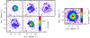 |
Fig. A.1 29SiO J = 2–1 maps extracted from low spatial-resolution data cube. Left: flux density (Sν) maps at different offset velocities with respect to the systemic velocity of the source (v* ~ −26.5 km s−1, Cernicharo et al. 2000) in LSR scale. The central velocity offset of each channel is shown at the bottom-left corner of each panel in kilometres per second. The width of each velocity channel is approximately 1 km s−1. The coordinates are given as offsets from the source position in arcseconds (see Sect. 2). The size and orientation of the synthetic beam are shown at the top-left corner inside the first panel. The contours shown in black correspond to 5σ, 25, 50, and 90% of the peak flux density (see Table 1). Right: moment zero map. The contours shown correspond to 10, 25, 50, 75, and 90% of the peak emission (see Table 1). |
Appendix B PV diagrams for the rest of the isotopologues
In this section we present the PV diagrams for the rest of the detected lines of isotopologues: the J = 2–1 line of 29SiO and 30SiO; the J = 5–4 and 6–5 lines of 29SiS, 30SiS, and Si34S; and the J = 2–1 line of 13CS, C34S, and C33S.
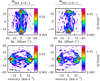 |
Fig. B.1 PV diagrams for the detected lines of the rest of SiO isotopologues. The contours shown in black correspond to 5σ, 25, 50, and 90% of the peak emission (see Table 1). Top: PV diagram of the flux density corresponding to a plane with a declination offset (see Sect. 2) equal to zero. Bottom: PV diagram of the flux density corresponding to a plane with a right ascension offset (see Sect. 2) equal to zero. |
References
- Agúndez, M., & Cernicharo, J. 2006, ApJ, 650, 374 [NASA ADS] [CrossRef] [Google Scholar]
- Agúndez, M., Cernicharo, J., & Guélin, M. 2007, ApJ, 662, L91 [NASA ADS] [CrossRef] [Google Scholar]
- Agúndez, M., Cernicharo, J., & Guélin, M. 2010, ApJ, 724, L133 [NASA ADS] [CrossRef] [Google Scholar]
- Agúndez, M., Fonfría, J. P., Cernicharo, J., et al. 2012, A&A, 543, A48 [NASA ADS] [CrossRef] [EDP Sciences] [Google Scholar]
- Agúndez, M., Cernicharo, J., Decin, L., Encrenaz, P., & Teyssier, D. 2014, ApJ, 790, L27 [NASA ADS] [CrossRef] [Google Scholar]
- Agúndez, M., Cernicharo, J., Quintana-Lacaci, G., et al. 2017, A&A, 601, A4 [NASA ADS] [CrossRef] [EDP Sciences] [Google Scholar]
- Balança, C., & Dayou, F. 2017, MNRAS, 469, 1673 [NASA ADS] [CrossRef] [Google Scholar]
- Bieging, J. H., & Tafalla, M. 1993, AJ, 105, 576 [NASA ADS] [CrossRef] [Google Scholar]
- Bohlin, R. C., Savage, B. D., & Drake, J. F. 1978, ApJ, 224, 132 [NASA ADS] [CrossRef] [Google Scholar]
- Carlström, U., Olofsson, H., Johansson, L. E. B., et al. 1990, From Miras to Planetary Nebulae: Which Path for Stellar Evolution? (France: Editions Frontieres), 170 [Google Scholar]
- Castor, J. I. 1970, MNRAS, 149, 111 [NASA ADS] [Google Scholar]
- Cernicharo, J., Kahane, C., Gomez-Gonzalez, J., & Guelin, M. 1986, A&A, 164, L1 [NASA ADS] [Google Scholar]
- Cernicharo, J., Gottlieb, C. A., Guelin, M., Thaddeus, P., & Vrtilek, J. M. 1989, ApJ, 341, L25 [NASA ADS] [CrossRef] [Google Scholar]
- Cernicharo, J., Guélin, M., & Kahane, C. 2000, A&AS, 142, 181 [NASA ADS] [CrossRef] [EDP Sciences] [Google Scholar]
- Cernicharo, J., Waters, L. B. F. M., Decin, L., et al. 2010, A&A, 521, L8 [NASA ADS] [CrossRef] [EDP Sciences] [Google Scholar]
- Cernicharo, J., Daniel, F., Castro-Carrizo, A., et al. 2013, ApJ, 778, L25 [Google Scholar]
- Cernicharo, J., Teyssier, D., Quintana-Lacaci, G., et al. 2014, ApJ, 796, L21 [NASA ADS] [CrossRef] [Google Scholar]
- Cernicharo, J., Marcelino, N., Agúndez, M., & Guélin, M. 2015, A&A, 575, A91 [NASA ADS] [CrossRef] [EDP Sciences] [Google Scholar]
- Cernicharo, J., Agúndez, M., Velilla Prieto, L., et al. 2017, A&A, 606, L5 [NASA ADS] [CrossRef] [EDP Sciences] [Google Scholar]
- Cherchneff, I. 2012, A&A, 545, A12 [NASA ADS] [CrossRef] [EDP Sciences] [Google Scholar]
- Dayou, F., & Balança C. 2006, A&A, 459, 297 [NASA ADS] [CrossRef] [EDP Sciences] [Google Scholar]
- De Beck, E., Lombaert, R., Agúndez, M., et al. 2012, A&A, 539, A108 [NASA ADS] [CrossRef] [EDP Sciences] [Google Scholar]
- Decin, L., Agúndez, M., Barlow, M. J., et al. 2010, Nature, 467, 64 [NASA ADS] [CrossRef] [PubMed] [Google Scholar]
- Denis-Alpizar, O., Stoecklin, T., Guilloteau, S., & Dutrey, A. 2018, MNRAS, 478, 1811 [NASA ADS] [CrossRef] [Google Scholar]
- Draine, B. T. 1978, ApJS, 36, 595 [NASA ADS] [CrossRef] [Google Scholar]
- Fonfría Expósito, J. P., Agúndez, M., Tercero, B., et al. 2006, ApJ, 646, L127 [NASA ADS] [CrossRef] [Google Scholar]
- Fonfría, J. P., Cernicharo, J., Richter, M. J., & Lacy, J. H. 2008, ApJ, 673, 445 [NASA ADS] [CrossRef] [Google Scholar]
- Fonfría, J. P., Fernández-López, M., Agúndez, M., et al. 2014, MNRAS, 445, 3289 [NASA ADS] [CrossRef] [Google Scholar]
- Fonfría, J. P., Cernicharo, J., Richter, M. J., et al. 2015, MNRAS, 453, 439 [NASA ADS] [CrossRef] [Google Scholar]
- Fonfría, J. P., Hinkle, K. H., Cernicharo, J., et al. 2017, ApJ, 835, 196 [NASA ADS] [CrossRef] [Google Scholar]
- Fonfría, J. P., Fernández-López, M., Pardo, J. R., et al. 2018, ApJ, 860, 162 [NASA ADS] [CrossRef] [Google Scholar]
- Gail, H.-P., & Sedlmayr, E. 1986, A&A, 166, 225 [NASA ADS] [Google Scholar]
- Gail, H.-P., & Sedlmayr, E. 2013, Physics and Chemistry of Circumstellar Dust Shells, eds. H.-P. Gail, & E. Sedlmayr (Cambridge, UK: Cambridge University Press), 2013 [Google Scholar]
- Gail, H.-P., Wetzel, S., Pucci, A., & Tamanai, A. 2013, A&A, 555, A119 [NASA ADS] [CrossRef] [EDP Sciences] [Google Scholar]
- Goldreich, P., & Kwan, J. 1974, ApJ, 189, 441 [NASA ADS] [CrossRef] [Google Scholar]
- Groenewegen, M. A. T. 1997, A&A, 317, 503 [NASA ADS] [Google Scholar]
- Groenewegen, M. A. T., Barlow, M. J., Blommaert, J. A. D. L., et al. 2012, A&A, 543, L8 [NASA ADS] [CrossRef] [EDP Sciences] [Google Scholar]
- Guélin, M., Lucas, R., & Cernicharo, J. 1993, A&A, 280, L19 [NASA ADS] [Google Scholar]
- Guélin, M., Patel, N. A., Bremer, M., et al. 2018, A&A, 610, A4 [NASA ADS] [CrossRef] [EDP Sciences] [Google Scholar]
- Habing, H. J.,& Olofsson, H. 2003, Asymptotic Giant Branch Stars, Astronomy and Astrophysics Library, eds., H. J. Habing, & H. Olofsson (New York: Springer), 2003 [Google Scholar]
- Hasegawa, T. I., Kwok, S., Koning, N., et al. 2006, ApJ, 637, 791 [NASA ADS] [CrossRef] [Google Scholar]
- Heays, A. N., Bosman, A. D., & van Dishoeck, E. F. 2017, A&A, 602, A105 [NASA ADS] [CrossRef] [EDP Sciences] [Google Scholar]
- Högbom, J. A. 1974, A&AS, 15, 417 [Google Scholar]
- Keady, J. J., & Ridgway, S. T. 1993, ApJ, 406, 199 [NASA ADS] [CrossRef] [Google Scholar]
- Kłos, J., & Lique, F. 2008, MNRAS, 390, 239 [NASA ADS] [CrossRef] [Google Scholar]
- Leão, I. C., de Laverny, P., Mékarnia, D., de Medeiros, J. R., & Vandame, B. 2006, A&A, 455, 187 [NASA ADS] [CrossRef] [EDP Sciences] [Google Scholar]
- Lucas, R., & Guélin, M. 1999, Asymptotic Giant Branch Stars, 191, 305 [NASA ADS] [Google Scholar]
- Lucas, R., Bujarrabal, V., Guilloteau, S., et al. 1992, A&A, 262, 491 [NASA ADS] [Google Scholar]
- Lucas, R., Guélin, M., Kahane, C., Audinos, P., & Cernicharo, J. 1995, Ap&SS, 224, 293 [NASA ADS] [CrossRef] [Google Scholar]
- Martin, P. G.,& Rogers, C. 1987, ApJ, 322, 374 [NASA ADS] [CrossRef] [Google Scholar]
- Mauron, N., & Huggins, P. J. 1999, A&A, 349, 203 [NASA ADS] [Google Scholar]
- Mauron, N., & Huggins, P. J. 2000, A&A, 359, 707 [NASA ADS] [Google Scholar]
- Mauron, N., de Laverny, P., & Lopez, B. 2003, A&A, 401, 985 [NASA ADS] [CrossRef] [EDP Sciences] [Google Scholar]
- McElroy, D., Walsh, C., Markwick, A. J., et al. 2013, A&A, 550, A36 [NASA ADS] [CrossRef] [EDP Sciences] [Google Scholar]
- McMullin, J. P., Waters, B., Schiebel, D., Young, W., & Golap, K. 2007, Astronomical Data Analysis Software and Systems XVI (San Francisco: ASP), 376, 127 [NASA ADS] [Google Scholar]
- Menten, K. M., Reid, M. J., Kamiński, T., & Claussen, M. J. 2012, A&A, 543, A73 [NASA ADS] [CrossRef] [EDP Sciences] [Google Scholar]
- Neugebauer, G., & Leighton, R. B. 1969, NASA SP, Washington: NASA, 1969 [Google Scholar]
- Olofsson, H., Johansson, L. E. B., Hjalmarson, A., & Nguyen-Quang-Rieu 1982, A&A, 107, 128 [NASA ADS] [Google Scholar]
- Olofsson, H., Bergman, P., Eriksson, K., & Gustafsson, B. 1996, A&A, 311, 587 [NASA ADS] [Google Scholar]
- Patel, N. A., Young, K. H., Gottlieb, C. A., et al. 2011, ApJS, 193, 17 [NASA ADS] [CrossRef] [Google Scholar]
- Pattillo, R. J., Cieszewski, R., Stancil, P. C., et al. 2018, ApJ, 858, 10 [NASA ADS] [CrossRef] [Google Scholar]
- Pety, J., & Rodríguez-Fernández, N. 2010, A&A, 517, A12 [NASA ADS] [CrossRef] [EDP Sciences] [Google Scholar]
- Ridgway, S., & Keady, J. J. 1988, ApJ, 326, 843 [NASA ADS] [CrossRef] [Google Scholar]
- Sánchez Contreras, C., Velilla Prieto, L., Agúndez, M., et al. 2015, A&A, 577, A52 [NASA ADS] [CrossRef] [EDP Sciences] [Google Scholar]
- Sahai, R., Wootten, A., & Clegg, R. E. S. 1984, ApJ, 284, 144 [NASA ADS] [CrossRef] [Google Scholar]
- Schöier, F. L., Fong, D., Olofsson, H., Zhang, Q., & Patel, N. 2006, ApJ, 649, 965 [NASA ADS] [CrossRef] [Google Scholar]
- Skinner, C. J., Justtanont, K., Tielens, A. G. G. M., et al. 1999, MNRAS, 302, 293 [NASA ADS] [CrossRef] [Google Scholar]
- Sobolev, V. V. 1960, Moving Envelopes of Stars (Cambridge: Harvard University Press) [CrossRef] [Google Scholar]
- Solomon, P., Jefferts, K. B., Penzias, A. A., & Wilson, R. W. 1971, ApJ, 163, L53 [NASA ADS] [CrossRef] [Google Scholar]
- Steer, D. G., Dewdney, P. E., & Ito, M. R. 1984, A&A, 137, 159 [NASA ADS] [Google Scholar]
- Toboła, R., Lique, F., Kłos, J., & Chałasiński, G. 2008, J. Phys. B At. Mol. Phys., 41, 155702 [CrossRef] [Google Scholar]
- Turner, B. E. 1971, ApJ, 163, L35 [NASA ADS] [CrossRef] [Google Scholar]
- Van de Sande, M., & Millar, T. J. 2019, ApJ, 873, 36 [NASA ADS] [CrossRef] [Google Scholar]
- Velilla Prieto, L., Cernicharo, J., Quintana-Lacaci, G., et al. 2015, ApJ, 805, L13 [NASA ADS] [CrossRef] [Google Scholar]
- Velilla Prieto, L., Sánchez Contreras, C., Cernicharo, J., et al. 2017, A&A, 597, A25 [NASA ADS] [CrossRef] [EDP Sciences] [Google Scholar]
- Wakelam, V., Loison, J.-C., Herbst, E., et al. 2015, ApJS, 217, 20 [NASA ADS] [CrossRef] [Google Scholar]
- Woitke, P. 2006, A&A, 452, 537 [NASA ADS] [CrossRef] [EDP Sciences] [Google Scholar]
- Zanchet, A., Roncero, O., Agúndez, M., & Cernicharo, J. 2018, ApJ, 862, 38 [NASA ADS] [CrossRef] [Google Scholar]
All Tables
All Figures
|
Fig. 1 SiO J = 2–1 maps extracted from high spatial-resolution data cube. Left: flux density (Sν) maps at different offset velocities with respect to the systemic velocity of the source (v* ~ −26.5 km s−1, Cernicharo et al. 2000) in LSR scale. The central velocity offset of each channel is shown at the bottom-left corner of each panel in kilometres per second. The width of each velocity channel is approximately 1 km s−1. The coordinates are given as offsets from the source position in arcseconds (see Sect. 2). The size and orientation of the synthetic beam are shown at the top-left corner inside the first panel. The contours shown in black correspond to 5σ, 2, 10, 50, and 90% of the peak flux density (see Table 1). Right: moment zero map. The contours shown correspond to 10, 25, 50, 75, and 90% of the peak emission (see Table 1). |
| In the text | |
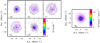 |
Fig. 2 As in Fig. 1, but for SiS J = 5–4. |
| In the text | |
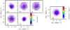 |
Fig. 3 As in Fig. 1, but for SiS J = 6–5. |
| In the text | |
|
Fig. 4 As in Fig. 1, but for CS J = 2–1. We note that there is a change of the spatial scale compared to that of Figs. 1–3. |
| In the text | |
|
Fig. 5 Position–velocity (PV) diagrams of detected lines of SiO, SiS, and CS main isotopologues. The contours shown in black correspond to 5σ, 2, 10, 50, and 90% of the peak emission (see Table 1 for details). Top: PV diagram of the flux density is shown corresponding to a plane with a declination offset (see Sect. 2) equal to zero. Bottom: PV diagram of the flux density is shown corresponding to a plane with a right ascension offset (see Sect. 2) equal to zero. |
| In the text | |
|
Fig. 6 Spectrum of the four lines towards the central pixel (0.″1 × 0.″1). This coincides with the position of the star (see Sect. 2) obtained from the ALMA-OTF merged observations (see also Table 1 for the basic parameters of the lines). The dashed red line represents the systemic velocity of the source (v* ~ −26.5 km s−1, Cernicharo et al. 2000)relative to the LSR. |
| In the text | |
|
Fig. 7 Azimuthal average of brightness distribution of four main isotopologue lines detected of CS (yellow line), SiS (green and red lines), and SiO (blue line). The flux density has been converted to brightness temperature, and the verticalscale is shown in logarithmic scale to improve the visualisation of the plot. The uncertainty intervals (3σ) are also shown in each curve with similar colours. The spatial scale is shown in units of the stellar radius and we also included an additional axis showing the angular scale in the bottom box. The equivalence between both scales is 1 R* ≃ 0.″019 (Ridgway & Keady 1988). On each box, the 5σ-level detection limit is shown in grey. We also indicate the maximum value of the brightness temperature for each distribution, which in all cases corresponds to the central pixel. We marked the levels in which the temperature decreased by half and by a factor of e of its maximum value. The results from the radiative transfer models (see Sect. 4) are shown as dashed black lines in each box. |
| In the text | |
|
Fig. 8 Spectrum of four lines (black histogram) towards star position as observed with IRAM-30 m telescope. The HPBW for the different frequencies is 20.″3 for SiO J = 2–1, 27.″1 for SiS J = 5–4, 22.″6 for SiS J = 6–5, and 25.″1 for CS J = 2–1. The coloured curves represent different synthetic spectra created with our radiative transfer code by using different input radialabundance profiles (see Sect. 4). The blue curves represent the model with which we used the radial abundance profiles shown in Fig. 9 (solid lines in that figure) as input, that is, the best fit profiles to the azimuthal average of the brightness distribution of the emission at the systemic velocity of the source from the ALMA and OTF-30 m merged data. The curves in magenta represent the model with which we used the same input abundance profile but without including any source of continuum radiation in the model, in order to evaluate the impact that IR radiative pumping, produced by the star and the dust, may have in the models. |
| In the text | |
|
Fig. 9 Radial abundance profiles (solid lines) used as input to model azimuthal averages in Fig. 7. The spatial scale is shown in units of the stellar radius and we also included an additional axis showing the angular scale. The equivalence between both scales is 1 R* ≃ 0.″019 ± 0.″003 (Ridgway & Keady 1988). The different radial profiles are created by using Gaussian components but due to conversion from logarithmic radial sampling the profiles display some abrupt changes. We note thatwe have used two different input abundance profiles for SiS, one for each of the lines (J = 5–4 and J = 6–5), aimed at obtaining two independent fits. Both profiles are very similar, and the true and single radial distribution of SiS may be between both profiles. The results from the chemical models described in Sect. 5 are represented by dashed lines of the same colours, except for the SiS line where both magenta and green colours are used. The fractional abundance value is relative to H2. |
| In the text | |
|
Fig. 10 Top: comparison between the gas spatial distribution of the J = 2–1 CS and SiO emission in orange and blue contours, respectively, and the dust distribution reported in Mauron & Huggins (1999) as seen in V +B, where the dark arcs and shells trace the location of the dust (background image in black and white colour scale). The small crosses in the image are also from Mauron & Huggins (1999), and represent the emission peaks of other molecular tracers, namely CN, HNC, and HC3 N reported in Lucas et al. (1995) and Lucas & Guélin (1999). Bottom: same contours representing J = 2–1 CS and SiO emission, with J = 2–1 CS contours in red (changed to improve the visualisation) and J = 2–1 SiO in blue, plotted over C3N N = 10–9 (black contours) and CN N = 1–0 (background image in pink colour scale) as reported by Agúndez et al. (2017). We note that the spatial scale between both figures is different. |
| In the text | |
|
Fig. A.1 29SiO J = 2–1 maps extracted from low spatial-resolution data cube. Left: flux density (Sν) maps at different offset velocities with respect to the systemic velocity of the source (v* ~ −26.5 km s−1, Cernicharo et al. 2000) in LSR scale. The central velocity offset of each channel is shown at the bottom-left corner of each panel in kilometres per second. The width of each velocity channel is approximately 1 km s−1. The coordinates are given as offsets from the source position in arcseconds (see Sect. 2). The size and orientation of the synthetic beam are shown at the top-left corner inside the first panel. The contours shown in black correspond to 5σ, 25, 50, and 90% of the peak flux density (see Table 1). Right: moment zero map. The contours shown correspond to 10, 25, 50, 75, and 90% of the peak emission (see Table 1). |
| In the text | |
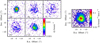 |
Fig. A.2 As in Fig. A.1, but for 30SiO J = 2–1. |
| In the text | |
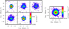 |
Fig. A.3 As in Fig. A.1, but for 29SiS J = 5–4. |
| In the text | |
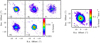 |
Fig. A.4 As in Fig. A.1, but for 29SiS J = 6–5. |
| In the text | |
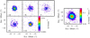 |
Fig. A.5 As in Fig. A.1, but for 30SiS J = 5–4. |
| In the text | |
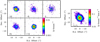 |
Fig. A.6 As in Fig. A.1, but for 30SiS J = 6–5. |
| In the text | |
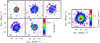 |
Fig. A.7 As in Fig. A.1, but for Si34S J = 5–4. |
| In the text | |
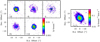 |
Fig. A.8 As in Fig. A.1, but for Si34S J = 6–5. |
| In the text | |
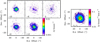 |
Fig. A.9 As in Fig. A.1, but for 13CS J = 2–1. |
| In the text | |
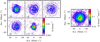 |
Fig. A.10 Asin Fig. A.1, but for C34S J = 2–1. |
| In the text | |
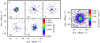 |
Fig. A.11 Asin Fig. A.1, but for C33S J = 2–1. |
| In the text | |
|
Fig. B.1 PV diagrams for the detected lines of the rest of SiO isotopologues. The contours shown in black correspond to 5σ, 25, 50, and 90% of the peak emission (see Table 1). Top: PV diagram of the flux density corresponding to a plane with a declination offset (see Sect. 2) equal to zero. Bottom: PV diagram of the flux density corresponding to a plane with a right ascension offset (see Sect. 2) equal to zero. |
| In the text | |
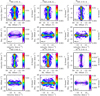 |
Fig. B.2 As in Fig. B.1, but for the SiS isotopologues. |
| In the text | |
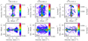 |
Fig. B.3 As in Fig. B.1 but for the CS isotopologues. |
| In the text | |
Current usage metrics show cumulative count of Article Views (full-text article views including HTML views, PDF and ePub downloads, according to the available data) and Abstracts Views on Vision4Press platform.
Data correspond to usage on the plateform after 2015. The current usage metrics is available 48-96 hours after online publication and is updated daily on week days.
Initial download of the metrics may take a while.