| Issue |
A&A
Volume 623, March 2019
|
|
|---|---|---|
| Article Number | A141 | |
| Number of page(s) | 18 | |
| Section | Interstellar and circumstellar matter | |
| DOI | https://doi.org/10.1051/0004-6361/201833001 | |
| Published online | 21 March 2019 | |
Multiwavelength study of the G345.5+1.5 region★
1
Aix-Marseille Université, CNRS, LAM, Laboratoire d’Astrophysique de Marseille, Marseille,
France
2
National Centre for Nuclear Research, ul. Hoża 69,
00-681 Warszawa, Poland
e-mail: This email address is being protected from spambots. You need JavaScript enabled to view it.
3
Joint ALMA Observatory (JAO), Alonso de Córdova 3107, Vitacura, Santiago, Chile
4
Departamento de Astronomía, Universidad de Chile,
Casilla 36-D,
Santiago, Chile
5
Jodrell Bank Centre for Astrophysics, School of Physics & Astronomy, University of Manchester,
Oxford Road,
Manchester M13 9PL, UK
6
Instituto Argentino de Radioastronomía, CONICET,
CCT-La Plata. C.C.5.,
1894 Villa Elisa, Argentina
7
European Southern Observatory, Alonso de Córdova 3107,
Vitacura, Santiago, Chile
Received:
11
March
2018
Accepted:
26
January
2019
Abstract
Context. The star formation process requires the dust and gas present in the Milky Way to self-assemble into dense reservoirs of neutral material where the new generation of stars will emerge. Star-forming regions are usually studied in the context of Galactic surveys, but dedicated observations are sometimes needed when the study reaches beyond the survey area.
Aims. A better understanding of the star formation process in the Galaxy can be obtained by studying several regions. This allows increasing the sample of objects (clumps, cores, and stars) for further statistical works and deeper follow-up studies. Here, we studied the G345.5+1.5 region, which is located slightly above the Galactic plane, to understand its star formation properties.
Methods. We combined Large Apex BOlometer CAmera (LABOCA) and 12CO(4−3) transition line (NANTEN2) observations complemented with the Hi-GAL and Spitzer-GLIMPSE surveys to study the star formation toward this region. We used the Clumpfind algorithm to extract the clumps from the 870 μm and 12CO(4−3) data. Radio emission at 36 cm was used to estimate the number of H II regions and to remove the contamination from the free–free emission at 870 μm. We employed color–color diagrams and spectral energy distribution (SED) slopes to distinguish between prestellar and protostellar clumps. We studied the boundedness of the clumps through the virial parameter. Finally, we estimated the star formation efficiency (SFE) and star formation rate (SFR) of the region and used the Schmidt–Kennicutt diagram to compare its ability to form stars with other regions of the Galactic plane.
Results. Of the 13 radio sources that we found using the MGPS-2 catalog, 7 are found to be associated with H II regions corresponding to late-B or early-O stars. We found 45 870 μm clumps with diameters between 0.4 and 1.2 pc and masses between 43 M⊙ and 3923 M⊙, and 107 12CO clumps with diameters between 0.4 and 1.3 pc and masses between 28 M⊙ and 9433 M⊙. More than 50% of the clumps are protostellar and bounded and are able to host (massive) star formation. High SFR and SFR density (ΣSFR) values are associated with the region, with an SFE of a few percent.
Conclusions. With submillimeter, CO transition, and short-wavelength infrared observations, our study reveals a population of massive stars, protostellar and bound starless clumps, toward G345.5+1.5. This region is therefore actively forming stars, and its location in the starburst quadrant of the Schmidt–Kennicutt diagram is comparable to other star-forming regions found within the Galactic plane.
Key words: ISM: clouds / HII regions / ISM: general
The LABOCA and CO maps, and Tables A.1–A.3 are also available at the CDS via anonymous ftp to cdsarc.u-strasbg.fr (130.79.128.5) or via http://cdsarc.u-strasbg.fr/viz-bin/qcat?J/A+A/623/A141
© ESO 2019
1 Introduction
Giant molecular clouds (GMCs) are huge and massive reservoirs of cold molecular gas. These objects are hierarchically structured into clumps (~0.2 to ~1 pc), cores (~0.2 pc), and filaments (~0.1 pc width, Arzoumanian et al. 2011) in which star formation is taking place. For instance, the Taurus B211 filament was found to undergo gravitational collapse with an associated supercritical mass per unit length, and is fragmented into several prestellar and protostellar cores (Palmeirim et al. 2013). Toward the Aquila complex, up to 75% of the prestellar core sample are found inside filaments (Könyves et al. 2015). The large star-forming complexes of our Galaxy within − 2° < b < 1° are found tohost 75% of ATLASGAL sources in which star formation activity has been detected (Csengeri et al. 2014). The abundance of gas and dust as well as the environmental conditions of these complexes are ideal for the formation of high-mass stars. This type of stars is very important because they can dictate the evolution of galaxies, and they dynamically and chemically regulate the interstellar medium (ISM) through powerful feedback (Krumholz et al. 2014). These mechanisms complicate our understanding of star formation since they affect the molecular cloud in which the stars are born. Stellar feedback such as outflows and jets is able to remove part of the material in the cluster, which slows down the accretion of the other stars (Wang et al. 2010; Murray et al. 2018) or adds some turbulence that halts the contraction of the cloud (Maury et al. 2009). More powerful feedback, such as photoionization or supernovae (SN) explosions, can strongly modify the cloud structure, favoring or stopping the formation of stars in it (Dale et al. 2013, 2015; Geen et al. 2016). Detailed studies about H II regions (Rivera-Ingraham et al. 2013; Figueira et al. 2017; Liu et al. 2017; Tigé et al. 2017)were obtained with the HOBYS program (Motte et al. 2010), which allowed us to better understand the properties of young stellar objects (YSOs) around these structures. In particular, massive dense cores (MDCs, M > 75 M⊙) are found atthe edges or in the filamentary parts of these regions, and they are good candidates for high-resolution observations (Figueira et al. 2018; Louvet et al. 2019).
While almost all the studies of star formation focus on regions in the Galactic plane that are covered by most of the surveys (|b| < 1°), other interesting star-forming regions are also found above and below. There are different advantages to extending a study to beyond the Galactic plane. First, the foreground and background dust emission that is unrelated to the region is less abundant1 (Anderson et al. 2014), and the estimation of physical parameters, such as the mass or the column density, is more accurate. Second, the superimposition of sources that lie at a different distances along the line of sight cannot be easily treated in general, and this difficulty is less frequently encountered when observing regions away from the Galactic plane. Finally, since these regions are not covered by most of surveys, they need dedicated observations and are therefore less well studied. Until now, only López et al. (2011) and López-Calderón et al. (2016) have conducted specifical studies of G345.5+1.5.
In this work, we present submillimeter and molecular observations of this region, which is located just above the Galactic plane, to better understand its star-forming properties and compare them to other known star-forming regions. Section 2 presents theG345.5+1.5 region. In Sect. 3 we detail the observations and the reduction process for the 870 μm and 12CO(4−3) observations, Sect. 4 presents the analysis made on the kinematic distance of the region, the Hα and radio continuum emission, and the properties of clumps that we extracted from the observations. Section 5 discusses the star-forming properties of the G345.5+1.5 structure. Finally, Sect. 6 presents the conclusions of this work.
2 G345.5+1.5 region
The G345.5+1.5 region is composed of two dusty ring-like structures referred to as G345.45+1.5 and G345.10+1.35 (see Fig. 1) and classified as H II regions (Caswell & Haynes 1987; Anderson et al. 2014). They are part of the GMC G345.5+1.0 (344.5° < ℓ < 346.5°, 1° < b < 1.8°). The region is associated with molecular gas emission observed between a local standard of rest velocity (VLSR) of −33 and −2 km s−1 with a peak at −13.6 km s−1, according to the Columbia University− Universidad de Chile 12CO(1−0) Survey of the Southern Galaxy (Bronfman et al. 1989). Using the rotation curve from Alvarez et al. (1990), López et al. (2011) estimated the near kinematic distance of 1.8 kpc to be most probable since the region would be at 262 pc above the Galactic plane if the far distance were chosen, 4.4 times the half-width at half-maximum (HWHM) of the Galactic molecular disk (Bronfman et al. 2000). At 1.2 mm, the GMC is composed of 201 clumps with diameters ranging from 0.2 to 0.6 pc, masses ranging from 3 M⊙ to 1.3 × 10³ M⊙, and a star formation efficiency (SFE) of 2% (López et al. 2011). The smallest ring, G345.45+1.5, mapped using APEX in the 13 CO(3−2) emission line by López-Calderón et al. (2016), could have been created by a SN explosion represented by the 36.6 cm source J165920-400424 in its center and expanding at a velocity of 1 km s−1. Because only 20% of the clumps are associated with infrared (IR) counterparts (López et al. 2011), this GMC seems to have a low stellar activity. Several clump candidates are starless, but they only contain 28% of the total mass forming clumps in the GMC.
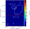 |
Fig. 1 1.2 mm emission map of the GMC G345.5+1.0 (López et al. 2011). The white ellipses represent the two rings of the region: G345.45+1.50 and G345.10+1.35. The area above the red dashed line represents the region we studied here. |
3 Observations and data reduction
3.1 870 μm APEX-LABOCA
The 870 μm continuum observations were carried out with the Large Apex BOlometer CAmera (LABOCA)2. LABOCA isa 295-pixel bolometer array developed by the Max-Planck-Institut für Radioastronomie (Siringo et al. 2007). Observations were carried out using the on-the-fly (OTF) mode to map four rectangular regions of δℓ × δb ~ 0.63° × 2.66° in size, fora total area of δℓ × δb ~ 2.15° × 2.66° in size, centered on (ℓ,b) = (345.4585°, 1.30413°). During the observations, the amount of precipitable water vapor (PWV) varied between 0.16 and 0.24 mm. Absolute flux calibrations were achieved through observations of Mars as primary calibrator and the stars N207 11R and VY CMa as secondary calibrators. The uncertainty due to flux calibration was estimated to be ~20%. The telescope focus and pointing were checked using the star η Carinae. Observations were smoothed down to a beam of 21.8′′. The data were reduced using the Comprehensive Reduction Utility for SHARC-2 software package (CRUSH-23 ; Kovács 2008) following the standard procedure, and this resulted in a rms of 0.2 Jy beam−1.
3.2 12CO(4−3) NANTEN2
Observations of the 12CO(4−3) transition line at 461.041 GHz were performed with the 4m NANTEN2 Telescope at Pampa La Bola between May and July 20124. The KOSMA SMART receiver is a dual-frequency, 2 × 8 pixel array receiver operating between 460 and 880 GHz. The half-power beam width (HPBW) at 461.041 GHz is 40′′ (0.35 pc at 1.8 kpc) and the velocity resolution is 0.7 km s−1. The smallest zones corresponding to 320′′ × 160′′ in size were observed using the OTF mode with a total observed area of 0.37° × 0.37° in size, centered on (ℓ,b) = (345.2194°, 1.30554°) and a grid size of 8.5′′ × 8.5′′. Each spectrum was observed for three seconds, giving a total observing time of 6.6 h. The data reduction was made with the IRAM software GILDAS/CLASS5. First, the data were filtered by opacity and noise temperature. Then, polynomial baselines of order three were subtracted from each spectrum and were then filtered by the RMS temperature of the fit. If needed, higher-order baselines were subtracted manually. After eliminating bad spectra (noisy and coupled signals, and holes), the data cube was produced by convolution with a Gaussian kernel with a grid of 20′′ × 20′′, giving a final rms of 0.24 K.
3.3 Ancillary data
Our study is complemented with near-IR, mid-IR, and centimetric data. We used the 2MASS6 (1.25−2.15 μm, Skrutskie et al. 2006) and Spitzer GLIMPSE7 (3.6−8 μm, Benjamin et al. 2003) observations to study the IR content of the region. The Supercosmos Hα Survey (SHS, Parker et al. 2005) and the Molonglo Galactic Plane Survey at 36 cm (MGPS, Murphy et al. 2007) are useful to study H II regions (Hα and free–free emission), which are powered by massive stars as well as the free–free contamination, which can affect the 870 μm observations. Herschel data from the Hi-GAL survey (Molinari et al. 2010a; Elia et al. 2017) between 70 (8′′) and 500 μm (36.6′′) were used to study the evolutionary stages of the clumps as well as the large-scale temperature and column density in the region.
4 Data analysis
4.1 Kinematic distance
López et al. (2011) rejected the far kinematic distance because it gives an elevation above the Galactic plane of 262 pc and a mass of 4.4 × 10⁷ M⊙. Using NH3, N2 H+, and CS emission lines coupled with H I absorption and self-absorption, Wienen et al. (2015) resolved the kinematic distance ambiguity (KDA) for the ATLASGAL clumps. Kinematic distances from 1.86 to 1.95 kpc were assigned to the clumps of the G345.5+1.5 region, but only up to b = 1° because the survey is limited in latitude. In Table 1 we summarize the different masers found toward the region and the different near kinematic distance computed from the central peak velocity using the Bayesian model of Reid et al. (2014). The typical uncertainty for the distance is ±0.6 kpc. Since the masers are distributed within different parts of the regions and the near kinematic distance agrees with the analysis of Wienen et al. (2015), the entire region should be located at approximately 1.8 kpc. Finally, in order to confirm whether the near kinematic distance is correct for G345.5+1.5, we show in Fig. 2 the J-band image from 2MASS of G345.5+1.5. This figure shows that the 1.2 mm emission is well correlated with the extinction structures, suggesting that the region lies on the near side of the Galaxy (Russeil et al. 2011).
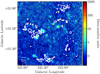 |
Fig. 2 2MASS J-band image of G345.5+1.5 with the 1.2 mm emission superimposed as a white contour at 0.1 Jy beam−1. |
4.2 Large-scale Hα emission around G345.5+1.5
Figure 3 presents an image from SHS. This shows that G345.5+1.5 is observed toward a large Hα emission structure. To determine whether the large-scale emission of ionized gas is associated with the region, we used the Wisconsin H-Alpha Mapper Sky Survey (WHAM-SS, Haffner et al. 2003)8 data with a spatial resolution of 1° and a velocity resolution of 2 km s−1. Figure 4a presents the Hα emission from SHS with the 8 μm emission and the integrated WHAM-SS. The spectroscopic data agree with the continuum because the inner white contour is centered on the main Hα emission region from SHS. By spatially averaging the datacube, we plot in Fig. 4b the integrated intensity versus VLSR together with the Gaussian fit to the data. The peak is located at −17.4 km s−1, which gives a near kinematic distance of 2.16 kpc. This is close to the distances found using the maser velocities (see Table 1). If the Hα emission were clearly associated with G345.5+1.5, we would have observed a correlation between the Hα and dust emission through extinction features. Nonetheless, Fig. 4a shows that the dust emission at 8 μm seems to be mostly uncorrelated with the Hα cloud and should be located behind it, the uncertainty being ~0.6 kpc for each kinematic distance. We searched in the public databases Vizier and SIMBAD for planetary nebulae, SN remnants, SN, white dwarfs, Wolf-Rayet stars, and novae to understand the presence of this Hα emission. We found Nova Sco 1437 (indicated by a black star in Fig. 3). Unfortunately, we found no additional information on this nova, and its relation with the large Hα structure, if any, is beyond the scope of this paper. No particular Hα spatial distribution is found toward the G345.10+1.35 structure, whose ring morphology might be explained by the expansion of an H II region powered by a cluster of OB stars toward its center.
Masers detected toward G345.5+1.5.
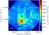 |
Fig. 3 Hα image from the SHS. The black rectangle represents the location of G345.5+1.5 as shown in Fig. 4a, and the black star represents the location of Nova Sco 1437. |
4.3 H II regions and radio emission
To determine if H II regions are associated with G345.5+1.5, we used the WISE catalog of Anderson et al. (2014). This catalog contains 8399 objects divided into known H II regions (detected radio recombination line, and/or Hα emission), H II region candidates (coincident with radio continuum emission), group candidates (coincident with radio continuum emission and found within an H II complex), and the radio-quiet sample (no radio continuum emission detected). Toward G345.5+1.5, 19 objects are found in the catalog, with five known H II regions, eight group candidates, and six radio-quiet objects. To confirm possible H II regions found in the candidate and radio-quiet samples, we used the 36 cm radio emission from the MGPS-2 survey (Murphy et al. 2007), the Hα emission from SHS, and the 8 μm emission from Spitzer. Emission at radio wavelength is less strongly affected by absorption than Hα emission, and G345.5+1.5 is covered by a huge Hα cloud. Moreover, it is a good tracer of H II regions because it represents the free–free process that is caused by the bremsstrahlung. Figure 5 presents the radio continuum emission at 843 MHz. In the catalog, we found five compact radio sources toward the region, but some very clearly visible compact radio sources were not included in the catalog. They were probably filtered out by the algorithm. We added them manually after checking that the peak brightness was higher than 5σMGPS (~10 mJy). Eight compact sources were added to the catalog, and they are presented in Fig. 5 and Table 2. The integrated flux of these radio sources was computed using aperture photometry and subtracting a background taken close to the radio source, but devoid of emission. In the following, we list the radio compact sources and estimate the spectral type of the star that is responsible for this radio emission if it has a clear effect on the surrounding medium seen at 8 μm.
Radio source 1
This source is listed as a radio-quiet object in the WISE catalog but presents a counterpart in MGPS-2 and at 8 μm. However, it could be a radial spike due to large brightness of radio source 8, and we did not consider it due to this uncertainty.
Radio source 2
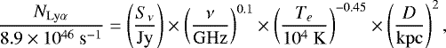
This radio source is correlated with an H II complex (Anderson et al. 2011) and is part of the group sample because it is spatially coincident with two known H II regions: G345.324+1.022 and G345.235+1.408, the first one being associated with radio source 7. Two layers of gas seen at 8 μm could represent dust pushed away by the expansion of the H II region. This radio source is also correlated with Hα emission, whose central stars are clearly visible in the SHS image. To determine the spectral type of the ionizing source, we computed the number of Lyα continuum photons from the MGPS-2 flux. We used the formula of Mezger & Henderson (1967):
 (1)
(1)
where Sν is the integrated flux, ν is the frequency of the observation, Te is the electron temperature (of about 104 K, Kurtz et al. 1999), D is the distance to the region, and NLy α is the ionization rate. The integrated flux at 843 MHz given in the MGPS-2 catalog for this source is 103.7 mJy. We found that NLy α = 2.9 × 1046 s−1, which corresponds to a B0.5V star according to Panagia (1973). Because of the correlation with Hα and 8 μm, this group object is considered as an H II region.
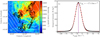 |
Fig. 4 Panel a: Hα image from the SHS toward the G345.5+1.5 region. The black contours represent the 8 μm emission (100, 300, 500 mJy sr−1), and the white contours represent the integrated Hα emission (from 35 to 530 R km s−1 with 55 R km s−1 steps) from the WHAM-SS. Panel b: spatially integrated Hα emission where the star-points represent the data and the red curve represents the Gaussian fit to the data. |
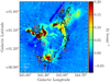 |
Fig. 5 Radio continuum map at 843 MHz. The 8 μm contours at 40 Jy beam−1 are superimposed. Red circles represent the compact radio sources. |
Radio source 3
The surrounding emission does not seem to be modified by this radio source, and no IR source is correlated with it. It is therefore possible that this source is located in the background, or might be an artifact because of the high ratio of its major to minor axis. Additionally, no particular emission in Hα is seen toward this source, and no counterpart is detected in the WISE catalog.
Radio source 4
This source presents no IR counterpart and has been proposed by López-Calderón et al. (2016) to be the remnant of a SN explosion causing the G345.45+1.5 bubble to expand at a velocity of 1 km s−1.
Detected 36 cm radio sources toward G345.5+1.5.
Radio source 5
This source, together with radio source 13, is enclosed in a WISE radio-quiet object. Nonetheless, a 843 MHz counterpart is detected and could represent a very young H II region, as identified by the QUaD Galactic Plane Survey (Culverhouse et al. 2011). The Hα cloud in the foreground does not allow us to see the Hα emission associated with this compact source. A curved 8 μm emission is seen around it and is probably due to the ionization pressure acting on the molecular material. This radio source has an integrated flux of 119.7 mJy, which corresponds to a B0.5V star (Panagia 1973).
Radio source 6
This source is listed in the group sample of the WISE catalog and has a counterpart at 843 MHz. Moreover, we clearly see a Hα counterpart in the form of a disk surrounded by 8 μm emission. Therefore this source is considered as an H II region. From the integrated intensity of 326.8 mJy, the corresponding spectral type of the ionizing star is a B0.5III star.
Radio source 7
This radio source is correlated with a far-IR source whose colors are characteristic of an ultra-compact (UC) H II region and CS(2−1) emission is detected toward it (Bronfman et al. 1996). It is part of a known H II region from Anderson et al. (2014), but no convincing Hα emission is seen toward this source, probably because of the contamination of the foreground Hα cloud. The integrated flux of the radio source is similar to that of radio source 6, giving a similar spectral type, B0.5III, for the ionizing star.
Radio source 8
This is the brightest radio source of the region with an integrated flux of 4.7 Jy and associated with an H II region in the WISE catalog. We have to note that a smaller radio-quiet object in the WISE catalog is present at the same location, but the low resolution of MGPS-2 does not allow for its detection. The radio source indicates that an O9V star could be the ionizing source. Observations of H II regions using atomic carbon C i[3P1 →3P0] toward this region reveals a velocity of −15.7 km s−1 (2 kpc, Huang et al. 1999), which is associated with a cluster of stars and CS(2−1) emission at the same velocity (Bronfman et al. 1996). Spectroscopy in the K band with the VLT toward strongly reddened sources embedded in UCH II regions reveals an early B, B0.5V, or O9V star (depending on the method used), which is part of a cluster with another O8V-BIV star (Bik et al. 2006), but at a distance of 1 kpc.
Radio source 9
This radio source is part of the WISE group sample. The integrated flux of 152.6 mJy corresponds to a B0.5V star and is correlated with Hα emission and an 8 μm curved emission arc. The star responsible for this radio source could be the −12.4 km s−1 IRAS source. A cluster of stars is also detected in this area, but at a velocity of −18.7 km s−1 (Kharchenko et al. 2013).
Radio sources 10, 11, and 12
These sources have no effect on their surrounding, and no Hα emission is associated with them. Since these sources were added to the catalog based on a visual inspection of the MGPS-2 map, they can be either artifacts, or foreground or background radio sources.
Radio source 13
This source is associated with a Red MSX Source (RMS) candidate (Lumsden et al. 2013), and the spectral type of the star responsible for this radio emission is B0.5V for a flux of 84.7 mJy. As discussed before, this radio source is close to radio source 5 and part of the WISE radio-quiet bubble sample (Anderson et al. 2014).
To summarize, three H II region candidates of the group sample (MGPS sources 2, 6, and 9) and one radio-quiet object (containing the MGPS sources 5 and 13) in the WISE catalog are considered as H II regions because of the distortion of the dust emission seen around them and/or associated Hα emission. MGPS source 1, associated with a radio-quiet object, can be an H II region or a radial spike artifact. The 5 remaining H II candidates of the group sample, despite the high probability of being an H II region (Anderson et al. 2014), could not be confirmed. Finally, 7 H II regions (up to 12, considering the group sample) are found toward G345.5+1.5, five MGPS sources are not related to H II regions, and it is possible that one of them represents a SN remnant (López-Calderón et al. 2016). Mosaics of these sources at 8 μm, 22 μm, Hα, and 36 cm are presented in Fig. B.1.
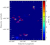 |
Fig. 6 APEX-LABOCA 870 μm emission map of G345.5+1.5 at 3σ (~0.6 Jy beam−1). The red polygons represent the 45 clumps detected using the Clumpfind algorithm. |
4.4 870 μm clumps detection
The G345.5+1.5 region is, as shown by López et al. (2011) with 1.2 mm data, fragmented into several clumps. Since the region extends up to a latitude of 1.9°, the ATLASGAL catalogs (Contreras et al. 2013; Csengeri et al. 2014) could not be used, and we had to extract the clumps independently. We used the CUPID implementation of the Clumpfind algorithm, fully described in Williams et al. (1994), to extract the clumps in the 870 μm continuum emission map. Clumpfind searches for emission peaks in the map and tracks them down until a contour level Clow with a contour step of Δinc, these parameters being provided by the user. In this method, a pixel can only belong to one clump. During the extraction, clumps whose size is smaller than the beam are rejected and the clump size is deconvolved in quadrature. For this study, we chose a Δinc of 2.5σ and a Clow of 3σ and also excluded the stripes seen in the map, which could lead to false detections. With this method and these initial parameters, we found a sample of 45 clumps, whose contours are superimposed on the 870 μm map in Fig. 6.
4.5 870 μm clump properties
4.5.1 Contamination by radio emission sources
Submillimeter emission is usually dominated by dust, but in star-forming regions, free–free or synchrotron emission can significantly contaminate this wavelength range and affect the computation of the physical parameters. Because we found 7–12 H II regions toward G345.5+1.5, we assumed that the contaminating radio emission comes entirely from the free–free process. To quantify this contamination, we compared the clump emission at 870 μm with the emission from MGPS-2 extrapolated at the same wavelength with a spectral index αff equal to − 0.1, which is characteristic of the free–free emission in diffuse H II regions (Mezger & Henderson 1967; Rumble et al. 2016). The 870 μm map was first convolved to the MGPS-2 resolution so that both observations could be compared. The percentage of contamination by the free–free emission is on average equal to 4% in our sample of 45 870 μm clumps, with a peak at 25%. While a close and strong radio source can highly contaminate a clump, low-mass clumps can be more affected than higher mass clumps even if the clump in question is not close to a radio source. For instance, six clumps present a contamination percentage higher than 10%. Three of these (clumps 3, 14, and 43) are found toward the H II region that is represented by the brightest radio source 8, and the three others (clumps 15, 22, and 24, associated with the contamination peak) are found toward the small ring G345.45+1.5, where most of the H II candidates are observed.
4.5.2 Physical parameters
The Clumpfind algorithm directly provides us physical parameters of the clumps, such as the standard deviation of the Gaussian, σc, that was used to defined the clump, as well as the integrated flux. As stated before, an automatic quadratic deconvolution was performed, and the flux was scaled accordingly. The physical diameter Dc of the clumps was taken to be the FWHM computed as 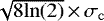 . The integrated intensity was corrected for the free–free contamination to obtain better estimates of the mass, column density, and volume density values. The mass was computed using the formula of Hildebrand (1983):
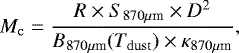 (2)
(2)
where R is the gas-to-dust ratio, S870μm is the integrated flux, D is the distance to the region, B870μm(Tdust) is the blackbody flux at 870 μm and at a temperature Tdust, and κ870μm is the opacity factor. We chose a value of Tdust = 20 K based on Deharveng et al. (2009) and Csengeri et al. (2017) at the same wavelength. We do not expect the temperatureto be lower than this, and the resulting mass can be considered as an upper limit. The parameter R is uncertain, but a value of 100 is commonlyused (Motte et al. 2010; Palmeirim et al. 2013; Csengeri et al. 2017). We followed the opacity law given in Ossenkopf & Henning (1994), 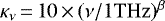 , with a spectral index β of 2, and a value of 1.18 cm2 g−1 was adopted at 870 μm. The value of the opacity factor is still debated because it depends on the dust environment and thus gives rise to an uncertainty of up to a factor of ~2 for the clump mass (Deharveng et al. 2012). We also have to note that ground-based telescopes filter the large-scale emission during the data reduction, and consequently, a fraction of the mass is lost (Csengeri et al. 2016). The average column and volume density werecomputed following
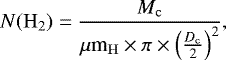 (3)
(3)
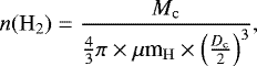 (4)
(4)
where μ is the mean molecular weight per hydrogen molecule set to 2.8 (Kauffmann et al. 2008), mH is the hydrogen mass, Mc is the clump mass, and Dc is the clump diameter. Table A.1 lists all the parameters for each of the 45 870 μm clumps corrected for the free–free emission, together with early class YSOs (see Sect. 4.7).
The clump extraction was also performed by López et al. (2011) using the 1.2 mm SIMBA observations and the Clumpfind algorithm. Because the observed region in their work is larger (see Fig. 1), the sample of 201 1.2 mm clumps was reduced to 166 in order to match the area observed by APEX. Therefore, they detected between three and four times more clumps than at 870 μm. This difference cannot be fully explained by the different resolution and the extraction method because the resolution is approximately the same and the extraction was made in the same way. When we assume that the dust emission behaves as a modified blackbody (Eq. (5)), the emission at 870 μm should be higher than at 1.2. mm and we should have recovered more clumps. However, the rms at 870 μm and 1.2 mm differs by a factor of 10 (σ1.2mm = 0.02 Jy beam−1), and the higher flux expected at 870 μm is not enough to compensate for this difference in the rms. Therefore, most of the weak emission clumps were completely removed during the extraction down to 3σ. Clumps whose emission peak was higher than 3σ but whose size was reduced because of the threshold were removed if they were smaller than the beam. This can be seen by comparing Figs. 1 and 6, where the ring part of G345.1+1.35 at ℓ = 344.9° is above 3σ1.2mm but below 3σ870μm. In this area, 42 clumps at 1.2 mm are detected, but we only recovered 2 of them at 870 μm. The same statement can be made for the northern part of G345.45+1.5, where 15 clumps could not be recovered, and around the concentration of clumps seen toward (b = 1.04°, 1.5°, 1.8°), where low-emission clumps are lost. When we use the integrated emission at 1.2 mm (see Table 5 of López et al. 2011)and Eq. (2), the total mass of the 1.2 mm clumps that are also found in this work is 2.1 × 10⁴ M⊙, and this agrees with the total dust mass of 2.2 × 10⁴ M⊙ at 870 μm. The total mass of clumps that are not recovered in our observation is equal to 4.1 × 10³ M⊙. This is about 17% of the total mass. The average clump mass that we do not detect is about 48 M⊙.
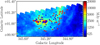 |
Fig. 7 Herschel 160 μm map with protostellar (blue) and prestellar sources (red) superimposed. |
4.6 Spatial distribution and properties of Herschel sources
To analyze the star formation around G345.5+1.5, we also used the catalog from the Hi-GAL survey (Molinari et al. 2010b; Elia et al. 2017). The extraction, made with the Cutex algorithm (Molinari et al. 2011) and the 70, 160, 250, 350, 500 μm bands from PACS (Poglitsch et al. 2010) and SPIRE (Griffin et al. 2010), is limited in latitude since PACS observations only reach ~1.2°. Toward the southern part of G345.5+1.5, 79 sources were extracted from the catalog together with their associated physical parameters (see Fig. 7). However, the distance chosen to compute the mass and the bolometric luminosity was not necessarily accurate (Traficante et al. 2018) and not given for 25 sources (set to an arbitrary value of 1 kpc in that case). To be consistent, the distance-dependent parameters were scaled to the G345.5+1.5 distance of 1.8 kpc. The diameter of the sources is equal to the deconvolved FWHM of the source footprints at 250 μm, and following the scheme of Bergin & Tafalla (2007), 21 sources are classified as cores (D < 0.2 pc) and 58 as clumps (0.2 pc ≤ D ≤ 3 pc). If a source was associated with an IR counterpart (see Sect. 4.7), it was included in the computation of the bolometric luminosity. Explanations about the spectral energy distribution (SED) fitting method and the computation of the physical parameters can be found in Elia et al. (2017). The uncertainty on the temperature and the envelope mass was derived from the SED fitting, and the uncertainty on the bolometric luminosity followed from them. The parameters of the Hi-GAL clumps are listed in Table A.2.
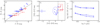 |
Fig. 8 Panel a: J−H vs. H−K color–color diagram. The line represents the location of an O9V star depending on the reddening (Tokunaga 2000). Blue and red crosses represent the IR counterparts that are considered Class III YSO or stars and early YSOs (from Class 0 to Class II). Panel b: [3.6]− [4.5] vs. [5.8]−[8.0] color–colordiagram. The blue ellipse and red box represent the location of Class III YSO or stars and YSOs following the models of Allen et al. (2004). Red crosses represent Class II (or earlier) YSOs located right of the blue dashed line that delineates the Class II and Class III stars. Panel c: SED from 3.6 μm to 8 μm. |
4.7 Association with IR sources
To characterize the star formation occurring in G345.5+1.5, we searched for IR counterparts in the GLIMPSE 3D (Churchwell et al. 2009)merged with the 2MASS Point Sources Catalog (PSC, Skrutskie et al. 2006) for each of the clumps detected at 870 μm and applied different criteria to the sources in order to exclude stars and keep the YSOs. We only kept sources with a close source flag of 0 (no sources within 3′′) to prevent contamination by other sources during the photometry step. Depending on their evolution, these sources can be grouped into different classes (André et al. 2000): main accretion phase (Class 0), late accretion phase (Class I), pre-main sequence (PMS) stars with protoplanetary disks (Class II), and PMS stars with debris disks (Class III). We used three different indicators: the J− H versus H−K, the [3.6]−[4.5] versus [5.8]−[8.0] color–color diagrams where YSOs and stars are expected to be at different locations, and the value of the SED slope from 3.6 to 8 μm, which can also be linked to the evolutionary class of the source (Lada 1987).
Figure 8 shows an example of the three indicators that we used for one clump. By assuming AV = 7.5AK with RV = 5 (Cardelli et al. 1989), where AV, AK, and RV are the visual extinction, the K-band extinction, and the visual extinction to color excess ratio, respectively, all the sources were dereddened with a visual extinction corresponding to the column density of the hosting clump that was computed with the relation of Bohlin et al. (1978). Following the extinction law of Indebetouw et al. (2005), we plotted on the J−H versus H−K color–color diagram the location of an O9V star (Tokunaga 2000) along a line representing the extinction due to the clump (Fig. 8a). Sources above this line are expected to represent mostly stars, while YSOs (Class 0-I-II) populate the bottom right corner of the plot as a result of the IR excess that originated in the circumstellar dusty layers. Following the disk and envelope models of Allen et al. (2004), the location of sources in the [3.6]−[4.5] versus [5.8]−[8.0] color–color diagram (Fig. 8b) is also representative of their class. Stars and Class III YSOs should be located within the blue ellipse centered on the origin, while Class II and Class I objects are found toward the red rectangle and above it, respectively. We selected the early YSOs as all the sources located to the right of the dashed blue line that defines the separation between Class III stars and Class 0-I-II objects. To avoid doubtful classifications, we excluded the YSOs that were classified differently following color–color diagrams. To confirm the class of the selected YSOs, we computed the slope of the SED between 3.6 and 8 μm (Fig. 8c). Each of the sources classified as Class 0–II has a slope higher than −1.5, the limit forClass II objects (Lada 1987; André et al. 2000). Class 0–II YSOs were found toward 26 of the 45 clumps (~58%) of the sample. However, it is possible that some sources are located in the foreground and not associated with the region, while others remain undetected if they are deeply embedded. We note that a high free–free contamination does not necessarily mean that the clump hosts IR counterparts because we searched for early class YSOs, while the high-mass stars emitting the ionizing flux are late class YSOs or stars. As explained in Sect. 4.5.1, a high free–free contamination can also be due to the low mass of a clump.
For the Hi-GAL sources, IR counterparts at 21 μm (MSX), 22 μm (WISE), and/or 24 μm (MIPSGAL) were considered only if a 70 μm source was found in the 250 μm emission footprint. To ensure the presence or absence of it, Elia et al. (2017) performed another extraction using a lower threshold than was used for the general extraction. If no 70 μm detection was found in this new extraction, no IR counterparts at 21, 22, or 24 μm were associated with the source. This method is fully described in Elia et al. (2017). In the sample of 79 Hi-GAL sources, 37 are prestellar and 42 are protostellar. Figure 7 shows the prestellar and protostellar sources superimposed on the 160 μm image. The densest parts and the inner parts of the region host more protostellar than prestellar sources, but a few sources contradict this tendency. The temperature of these protostellar clumps given by their SED is found to be higher than that of the prestellar clumps (Ragan et al. 2012; Liu et al. 2017) because of the ongoing star-formation that occurs inside, even if the temperature given by the SED is an average over the clump and does not indicate the temperature of the inner parts. The distribution is shown in Fig. 9, where the temperature of the prestellar clumps ranges from 8 to 18 K and peaks at (14 ± 0.9) K, while for protostellar clumps, it ranges from 10 to 30 K and peaks at (16 ± 1.2) K (Ohashi et al. 2016; Olmi et al. 2016; Elia et al. 2017). When we compared the 870 μm clumps and Hi-GAL sources below b = 1.2° with respect to their IR counterpart, we observed a good agreement between the distribution of star-forming (protostellar) and non-star-forming (prestellar) clumps, where only one of them is classified as protostellar with the Hi-GAL criteria and as prestellar with 870 μm.
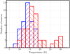 |
Fig. 9 Histogram of the source temperatures derived from the SED. Prestellar sources are plotted in blue and protostellar sources in red. |
4.8 Temperature and column density maps
Using the Hi-GAL data, we created the temperature and column density maps for the G345.5+1.5 region using a pixel-to-pixel SED fitting from 160 μm onward. The observations were convolved tothe resolution of the 500 μm map (36.6′′) and resampled to 14′′ pix−1. The pixel-to-pixel fitting was performed using a modified blackbody model:
 (5)
(5)
where the parameters are the same as for Eq. (2). The resulting temperature and column density maps are shown in Figs. 10a and 10b. However, the spatial area observed with PACS extends to b = 1°, which limitsthe spatial coverage of the temperature and column density maps. To fully exploit the spatial coverage of Herschel, we also constructed them using SPIRE bands alone, which extends the spatial coverage to b = 1.5°. These new maps give more spatial information at the expense of loosing accuracy in the obtained SEDs, and they are shown in Figs. 10c and 10d with the same color scale. To understand how these maps differ according to the number of bands used, we plot in Fig. 11 the temperature and column density obtained using SPIRE bands only versus those obtained using PACS and SPIRE bands, respectively. The obtained Pearson correlation coefficient for the linear least-squares regression is 0.92 and 0.98 for the temperature and the column density, respectively, which shows that the two sets of maps are in good agreement. When using SPIRE bands alone, the temperature is higher by less than 5 K. The peak of the SED occurs generally around 160 μm in our case, and using this band allows us to better constrain its peak and therefore the temperature. When only SPIRE bands are used, the peak will tend to be less well constrained as the temperature increases. Consequently, there is a significant deviation by 10−15 K for a few pixels when TPACS > 32 K. Concerning the column density maps, the differences are lower than a factor of 2. Three areas of high temperature (>27 K) are observed: one toward the small ring G345.5+1.45 (difficult to analyze because of its proximity to the edge of the survey), corresponding to bright radio emission and H II candidates, and the other two around b = 1°, corresponding to known H II regions. The temperature of 25−30 K is in agreement with other temperatures found around H II regions (Anderson et al. 2012; Liu et al. 2017). The other part of the ring has a temperature of 22 K, while the temperature outside the region is 18 K. Some very cold areas are found at 16 K and are correlated with high-column density (> 5 × 1022 cm−2) areas and with emission observed at 870 μm and 1.2 mm.
4.9 12CO emission spectrum
In Fig. 12 we show the spatially averaged main-beam temperature (TMB) of the 12CO(4−3) emission line over the entire observed area with respect to VLSR. We observed the two-component velocity structure along the GMC, first seen in the 12CO(1−0) line by Bronfman et al. (1989), in the CS(2−1) line (main component only) by Bronfman et al. (1996) and more recently in the 12CO(3−2) and 13 CO(3−2) for G345.45+1.5 by López-Calderón et al. (2016). Using a Gaussian fitting, we found the main and second peak to be located at −12.8 and −24.1 km s−1. Figure 13a represents the integrated emission around the main peak, between −21 and 1.4 km s−1, where the two rings, G345.45+1.5 and G345.10+1.35, are clearly visible. Figure 13b displays the integrated emission around the secondary peak, between −32.2 and −21.7 km s−1. The velocityaveraged TMB around the secondary peak is so weak that the emission over the entire range of velocity is similar to that of the main peak. This weak 12CO emission mainly arises around G345.45+1.5 (López-Calderón et al. 2016), and no counterparts in the dust emission seen by Herschel as well as extinction features in the near-IR are observed. When the model of Reid et al. (2014) is assumed, this gas is located either at a distance of 2.6±0.5 or 14.1±0.5 kpc and is therefore not associated with G435.5+1.5. The emission peak of the map is located at (ℓ,b) = (345.19°,1.03°) with an intensity of 26.9 K, a line width of 4.9 km s−1, and an integrated intensity of 220 K km s−1 corresponding to a known H II region of the WISE catalog associated with the brightest radio source 8. Another peak is also seen toward the H II regions and radio sources 2 and 7. A bright area is seen towards G345.45+1.5, corresponding to the maximum line width of 12.8 km s−1 and is associated with a young high-mass star (Guzmán et al. 2014). Both rings are composed of several clumps where the largest concentration is found for G345.45+1.5 (López-Calderón et al. 2016) and to the south of G345.10+1.35.
4.10 12CO clump detection and properties
To extract the clumps detected in the 12CO observations, we used the same algorithm as for the 870 μm clump extraction with a lowest level of detection at 3σ and an increment step of 2σ. From the 416 CO clumps extracted from the whole data cube, we removed those touching the edges of the map and whose temperature peak was lower than 5σ. We ended up with a sample of 107 12CO clumps, whose histogram is presented in Fig. 12 together with the spectra integrated over the entire cube. As expected, we found the same behavior between the spectrum and the histogram. The blue line divides the histogram at −21.7 km s−1, where 12 clumps belongs to the second peak range (−32.2 to −21.7 km s−1) and 95 clumps to the main peak range (−21 to 1.4 km s−1). Only this latter group of clumps, associated with G345.5+1.5, was considered. As for the previous extraction, the Clumpfind output catalog gives us the standard deviation of the Gaussian representing the clump as well as the integrated flux. In order to compute the mass of the clumps, we scaled their emission to that of the 12CO(1−0) and used a CO-to-H2 conversion factor (XCO) of 2 × 1020 cm−2 (K km s−1)−1, the value recommended by Bolatto et al. (2013), with an uncertainty of ±30%. To compute this scale factor, the 12CO(1−0) and 12CO(4−3) data were integrated over the spatial area and main peak velocity range. The ratio between the two transition levels is equal to 0.15, which is comparable to the Orion-A GMC (Ishii et al. 2016, see their Fig. 11a). We have to note that the mass of the region is different from the mass given in López et al. (2011) because of the different XCO value used and the larger spatial coverage, which corresponds to the G345.5+1.0 GMC, while only a fraction of this region is studied in the present work. At 3σ, we estimate the completeness limit to be equal to ~7 M⊙. The parameters of the 95 12CO(4−3) clumps are listed in Table A.3. The mass and the diameter of the clumps extend from 28 to 9432 M⊙, with a median of 795 M⊙, and from 0.35 to 1.34 pc, with a median of 0.7 pc.
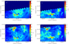 |
Fig. 10 Temperature and column density maps using the 160 μm and SPIRE bands (panels a and b) and SPIRE bands alone (panels c and d). |
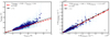 |
Fig. 11 Panel a: temperature obtained with SPIRE bands alone vs. PACS and SPIRE bands. Panel b: column density obtained with SPIRE bands alone vs. PACS and SPIRE bands. The black continuous line is the one-to-one relation, and the red dashed line is the linear fit to the data. |
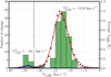 |
Fig. 12 Averaged spectra of the 12CO(4−3) data. The red and blue curves correspond to the best Gaussian fitting for the main and weakest component, respectively. Histogram of the 107 CO-clump velocities, where the blue line at −21.7 km s−1 represents the edge between the main peak and the secondary peak. |
5 Discussion
5.1 Star-forming clumps in G345.5+1.5
In Sects. 4.4 and 4.6 we showed that the dust emission is distributed into several cores and clumps where star formation is taking place depending on the association with IR counterparts. Because the agreement with IR counterparts found for the 870 μm clumps and Hi-GAL sources in the same area (b < 1.2°) is good, we are confident about the IR counterparts found for the 870 μm clumps, where no Herschel data are available. The percentage of star-forming clumps for the 870 μm clumps or Hi-GAL sources (58 and 53%, respectively) shows that G345.5+1.5 is an active star-forming region, in agreement with the numerous known and candidate H II regions found toward it. Part of the remaining starless clumps where no IR counterparts are found might be future sites of star formation under the condition that they are gravitationally bound. As in Elia et al. (2017) or Palmeirim et al. (2017), we considered a clump as bound when its mass was higher than MBal > 460 M⊙ × r1.9, with r in parsec (Larson 1981). We found 34 bound and three unbound prestellar clumps in the Hi-GAL sample, while all 870 μm clumps without an IR counterpart are bound. This result is in agreement with Ward-Thompson et al. (2016), who found that SCUBA-2 (850 μm) prestellar cores are mostly located in the region of the mass versus FWHM diagram where bound cores are found, while Herschel cores can also be found below, in the unbound core region. This is related to the fact that SCUBA-2 mostly detects high-surface brightness sources that tend to be bound, while Herschel can detect lower brightness structures. Therefore, many sources seem to be able to form stars in the future. Because G345.5+1.5 appears to have several H II regions, we also used the criteria of Baldeschi et al. (2017) to predict whether high-mass star formation can occur in the future. According to their work, the mass limit at which a clump is able to form high-mass stars is given by Mlim > 1282 M⊙ × r1.42, with r in parsec. We found that 15 of the 45 870 μm clumps and 32 of the Herschel bound sources are good candidates. These objects are located toward parts of the region where the high-density and low temperature conditions are ideal for the formation of massive stars.
Based on the submillimetric to bolometric luminosity ratio (Lsub/Lbol where 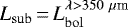 ), which is linked to the evolutionary stage, we found that this ratio is lower than 1% in only five Herschel sources (André et al. 2000, 1993), corresponding to Class I objects at least. One corresponds to the YSO represented by radio source 6 (and to an H II bubble), two correspond to sources found toward radio source 8, and the two last ones are found in the south of the region. In total, 94% are Class 0 sources toward G345.5+1.5 (up to b = 1.2°), showing that a new generation of stars is currently under formation. We also plotted the sample of Hi-GAL sources in the Lbol versus Menv diagram together with the evolutionary paths of Saraceno et al. (1996) and Molinari et al. (2008). In this model, the paths are composed of an accelerating accretion phase and an envelope clean-up phase based on the turbulent core model of McKee & Tan (2003). Figure 14 shows the Hi-GAL sources superimposed on the evolutionary diagram according to their protostellar and prestellar nature. As expected, the majority of the sources are found in the accelerating accretion phase, and the sources having an IR counterpart are found in a later evolutionary stage than starless sources. This is expected because Herschel wavelengths characterize the early stages of star formation.
5.2 Gravitational stability of the clumps
In order to determine whether the 12CO clumps we extracted in Sect. 4.10 can form stars, we studied their gravitational stability through their virial parameter α (Bertoldi & McKee 1992). This is defined as the kinetic (EK) to the gravitational energy (EG) ratio, which also translates as
 (6)
(6)
where σv is the line width of the clump spectrum, R is the radius of the clump, and G is the Newton constant. Depending on the value of α, clumps are either supercritical (α < 1, collapsing), critical (α = 1, in equilibrium), or subcritical (α > 1, unbound). Figure 15 shows the virial parameter for the sample of clouds with respect to their mass. The virial ratio of more than two-thirds of the clumps (76%) is below the critical value, and they are localized in the south of G345.45+1.5 (where several H II region candidates are found) and along the G345.5+1.35 ring, while the unbound clumps are found around these structures where the density is lower. This indicates that roughly half of the clumps are collapsing/will collapse in the future if no external effects counteracting the gravitation are at work. The magnetic field could play this role, as proposed by Kauffmann et al. (2013). Several low α clumps were found toward the ring at b = 344.9°, but no H II regions (known, candidates, or radio-quiet regions) were found in the WISE catalog (Anderson et al. 2014), suggesting that this part of the G435.5+1.5 region is not actively forming stars at the moment but is expected to do so in the future. The median value of α in the region is 0.94 and is on the same order of magnitude as the value found for the southern Galactic plane sample of ATLASGAL clumps by Wienen et al. (2018). Additionally, a decreasing virial parameter with increasing clump mass was observed and follows a power law of the form α = γ × Mβ. This behavior of the virial parameter was also reported by Lada et al. (2008) and Foster et al. (2009), which implies that the massive clumps tend to have a low virial parameter. It has also been reported that the value of the exponent in this power law is enclosed between −1 and 0 in different studies (Pillai et al. 2011; Lada et al. 2008; Wienen et al. 2018; Tan et al. 2013). For our sample of clumps, the fit gives γ = 9.9 ± 0.1 and β = − 0.38 ± 0.04. Therefore, the exponent found for G345.5+1.5 is in the common range of exponent values observed toward low- and high-mass star-forming regions. As explained by Kauffmann et al. (2013), this implies that the mass-size and line width-size relations here are also similar to that of their samples.
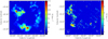 |
Fig. 13 Integrated emission over −21 and 1.4 km s−1 (panel a) and −32.2 and −21.7 km s−1 (panel b). |
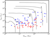 |
Fig. 14 Lbol–Menv diagram with the evolutionary tracks of Molinari et al. (2008) and the sample of sources superimposed on it. Protostellar sources (with a 70 μm counterpart)are shown in blue and prestellar sources (without a 70 μm counterpart) in red. |
5.3 Star formation rate and star formation efficiency of G345.5+1.5
Based on the number of compact radio sources identified at 843 MHz and on the analysis of their surroundings, G345.5+1.5 contains at least seven high-mass stars. This number is a lower limit because we considered that the resulting H II regions come from a single star, and we did not consider candidate H II regions either. Moreover, the absorption of the Lyα continuum radiation by the surrounding dust can also contribute to lower the true ionizing rate and therefore the number of massive stars in this region. We made another computation to determine the approximate number of high-mass stars by taking into account all the radio continuum emission present within the G345.5+1.5. Using aperture photometry, we found a total integrated intensity of 39 Jy with an average background emission of 0.001 Jy beam−1 estimated inan empty region. Because the H II regions are powered by O9/B0.5 stars (see Table 2), we assumed an average spectral type O9.5 for all the ionizing stars. Based on the calibrations of Martins et al. (2005), their mass is approximately equal to 20 M⊙ with NLy α = 1048.5 s−1. We estimatethat 27 O9.5 stars are responsible for the free–free emission in the region. To compute the star formation properties of this region, namely the star formation rate (SFR) and the SFE, we assumed that the distribution of stellar mass followed the Kroupa initial mass function (IMF, Kroupa 2002):
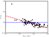 |
Fig. 15 Virial parameter of the 12CO clumps withrespect to their mass. The blue line represents the value for a cloud in equilibrium. |
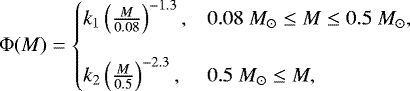 (7)
(7)
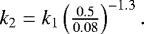 (8)
(8)
The normalization constant k2 was computed assuming that the number of stars with a mass from 8 to 20 M⊙ corresponds to the number of O9.5V stars found. The total stellar mass is obtained from 0.08 to 20 M⊙. We assumed a typical massive protostellar lifetime, t* = 0.2 Myr (Duarte-Cabral et al. 2013), the SFE as SFE = M*/(MG345 + M*), and the SFR as SFR = M*/t*, where M* is the expected total stellar mass equal to  and MG345 is the mass of the region equal to 1.2 × 10⁵ M⊙. The values are reported in Table 3. Compared to W43-MM1 and RCW 106 (Louvet et al. 2014; Nguyen et al. 2015), where the resulting SFE was computed with the Kroupa (from 0.08 to 150 M⊙, second approach) and Salpeter IMF (from 0.08 to 50 M⊙), respectively, the SFE of G345.5+1.5 is found to lie in between. The SFR, computed in each case with the same t*, is equal to 0.25 and 0.006 M⊙ yr−1 for RCW 106 and W46 MM1, respectively. The SFR of G345.5+1.5 is in between the value of these two regions, which have the potential to become starburst regions. In agreement with the H II regions and protostellar sources found within it, G345.5+1.5 will continue to actively form stars in the future.
A better way to characterize the star formation occurring in a GMC is by computing the SFR density (ΣSFR), which is independent of the area. However, ΣSFR is dependent on the way the surface is chosen. In the case of a ring structure, we could choose either to enclose the whole cloud or to enclose the ring alone because the interior is mostly devoid of emission (see Figs. 1, 6, 10d). We chose the latter method, and the area corresponding to the emission ring is 265 pc2. The ΣSFR is six times higher than the value of RCW 106, but 200 times lower than for W43 MM1. This latter region couldbe in a process of collision, which would drastically increase the high-mass star formation (Motte et al. 2003; Nguyen-Luong et al. 2013) and could explain this high value. Despite this difference, G345.5+1.5 also has a high ΣSFR for a star-forming region. Another way to compute the SFR is by using a scaling relation, as was done in Nguyen-Luong et al. (2016), who compared different star-forming regions with regard to different parameters. They made use ofradio continuum emission at 1.42 GHz to determine the SFR of these regions extracted from the 12CO(1−0) survey (Bronfman et al. 1989) through the relation of Murray & Rahman (2010). In that case, the SFR of G345.5+1.5 drops to 3.5 × 10⁻⁴ M⊙ yr−1 using their method and is lower by an order of magnitude at least compared to the massive molecular cloud complexes (MCC) listed in their work, such as W 51 or Cygnus-X. However, this value is comparable to the SFR values computed by Veneziani et al. (2017) using Monte Carlo procedures with Hi-GAL and 12CO observations toward four GMCs of the fourth quadrant for approximately the same mass of gas (see their Table 4). The values for ΣSFR range from approximately 10−2 to 10 M⊙ yr−1, G345.5+1.5 being comparable to Cygnus-X or or W 48. Finally, to determine whether the region is really efficient at forming stars, the SFR of the region needs to be compared to the available quantity of gas. In the Schmidt–Kennicutt diagram, log (ΣSFR) versus log (Σgas), the region is located in the starburst quadrant (see Fig. 6 of Nguyen-Luong et al. 2016), which confirms that it is an active star-forming region, as is also clear from the several H II regions and the H II region candidates (Anderson et al. 2014) as well as from the protostellar and bound sources found in the Hi-GAL survey.
Properties of different star-forming regions.
6 Conclusions
We used the APEX-LABOCA 870 μm and NANTEN2 12CO(4−3) molecular line, complemented with 2MASS, Spitzer, and Herschel Hi-GAL observations, to study the G345.5+1.5 region. The large-scale distribution of Hα emission that is found spatially close to the region is also close in distance and probably mainly in front because very few extinction features are observed in Hα despite the kinematic distance that is assigned. An analysis of the radio-compact sources at 36 cm in association with the WISE catalog of H II regions confirmed the presence of seven late-B and early-O high-mass stars, which could increase to 12. The region is composed of 45 870 μm clumps, and 79 Hi-GAL sources are found in the south (b < 1.2°). The high percentage, more than 50%, of IR counterparts found toward these clumps indicates that a new generation of stars will emerge. In particular, high-mass stars are able to form in most of the clumps because their mass is above the limit proposed in the literature. The boundedness of the prestellar clumps also indicates that most of them will be able to host star formation in the future. This is in agreement with the high percentage of bound 12CO clumps and its SFR and ΣSFR, which are comparable to other well-known star-forming regions of the Galaxy. Located in the starburst quadrant of the Schmitt–Kennicutt diagram, G345.5+1.5 is currently actively forming stars and is therefore an interesting region that merits follow-up studies to better understand star formation.
Acknowledgements
L.B. acknowledges support from CONICYT project Basal AFB-170002.
Appendix A Properties of the 870 μm, Hi-GAL, and 12CO clumps
Properties of the 45 870 μm clumps.
Properties of the Hi-GAL sources toward G345.5+1.5.
Properties of the 95 12CO(4−3) clumps extracted from the cube that belong to the main peak.
Appendix B H II region images
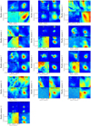 |
Fig. B.1 Mosaic of the radio sources discussed in Sect. 4.3 that were observed with Spitzer 8 μm, WISE 22 μm, SHS Hα, and MGPS 36 cm. |
References
- Allen, L. E., Calvet, N., D’Alessio, P., et al. 2004, ApJS, 154, 363 [NASA ADS] [CrossRef] [Google Scholar]
- Alvarez, H., May, J., & Bronfman, L. 1990, ApJ, 348, 495 [NASA ADS] [CrossRef] [Google Scholar]
- Anderson, L. D., Bania, T. M., Balser, D. S., & Rood, R. T. 2011, ApJS, 194, 32 [NASA ADS] [CrossRef] [Google Scholar]
- Anderson, L. D., Zavagno, A., Deharveng, L., et al. 2012, A&A, 542, A10 [NASA ADS] [CrossRef] [EDP Sciences] [Google Scholar]
- Anderson, L. D., Bania, T. M., Balser, D. S., et al. 2014, ApJS, 212, 1 [NASA ADS] [CrossRef] [Google Scholar]
- André, P., Ward-Thompson, D., & Barsony, M. 1993, ApJ, 406, 122 [NASA ADS] [CrossRef] [Google Scholar]
- André, P., Ward-Thompson, D., & Barsony, M. 2000, Protostars and Planets IV (Tucson, AZ: University of Arizona Press), 59 [Google Scholar]
- Arzoumanian, D., André, P., Didelon, P., et al. 2011, A&A, 529, L6 [Google Scholar]
- Baldeschi, A., Elia, D., Molinari, S., et al. 2017, MNRAS, 466, 3682 [NASA ADS] [CrossRef] [Google Scholar]
- Benjamin, R. A., Churchwell, E., Babler, B. L., et al. 2003, PASP, 115, 953 [NASA ADS] [CrossRef] [Google Scholar]
- Bergin, E. A., & Tafalla, M. 2007, ARA&A, 45, 339 [NASA ADS] [CrossRef] [Google Scholar]
- Bertoldi, F., & McKee, C. F. 1992, ApJ, 395, 140 [NASA ADS] [CrossRef] [Google Scholar]
- Bik, A., Kaper, L., & Waters, L. B. F. M. 2006, A&A, 455, 561 [NASA ADS] [CrossRef] [EDP Sciences] [Google Scholar]
- Bohlin, R. C., Savage, B. D., & Drake, J. F. 1978, ApJ, 224, 132 [NASA ADS] [CrossRef] [Google Scholar]
- Bolatto, A. D., Wolfire, M., & Leroy, A. K. 2013, ARA&A, 51, 207 [Google Scholar]
- Bronfman, L., Alvarez, H., Cohen, R. S., & Thaddeus, P. 1989, ApJS, 71, 481 [NASA ADS] [CrossRef] [Google Scholar]
- Bronfman, L., Nyman, L.-Å., & May, J. 1996, A&AS, 115, 81 [NASA ADS] [Google Scholar]
- Bronfman, L., Casassus, S., May, J., & Nyman, L.-Å. 2000, A&A, 358, 521 [NASA ADS] [Google Scholar]
- Cardelli, J. A., Clayton, G. C., & Mathis, J. S. 1989, ApJ, 345, 245 [NASA ADS] [CrossRef] [Google Scholar]
- Caswell, J. L. 2004, MNRAS, 349, 99 [NASA ADS] [CrossRef] [Google Scholar]
- Caswell, J. L., & Haynes, R. F. 1983, Aust. J. Phys., 36, 361 [NASA ADS] [CrossRef] [Google Scholar]
- Caswell, J. L., & Haynes, R. F. 1987, A&A, 171, 261 [NASA ADS] [Google Scholar]
- Caswell, J. L., & Vaile, R. A. 1995, MNRAS, 273, 328 [NASA ADS] [CrossRef] [Google Scholar]
- Caswell, J. L., Batchelor, R. A., Forster, J. R., & Wellington, K. J. 1983, Aust. J. Phys., 36, 401 [NASA ADS] [CrossRef] [Google Scholar]
- Caswell, J. L., Vaile, R. A., & Forster, J. R. 1995a, MNRAS, 277, 210 [NASA ADS] [Google Scholar]
- Caswell, J. L., Vaile, R. A., Ellingsen, S. P., & Norris, R. P. 1995b, MNRAS, 274, 1126 [NASA ADS] [Google Scholar]
- Caswell, J. L., Vaile, R. A., Ellingsen, S. P., Whiteoak, J. B., & Norris, R. P. 1995c, MNRAS, 272, 96 [NASA ADS] [CrossRef] [Google Scholar]
- Churchwell, E., Babler, B. L., Meade, M. R., et al. 2009, PASP, 121, 213 [NASA ADS] [CrossRef] [Google Scholar]
- Cohen, R. J., Masheder, M. R. W., & Caswell, J. L. 1995, MNRAS, 274, 808 [NASA ADS] [Google Scholar]
- Contreras, Y., Schuller, F., Urquhart, J. S., et al. 2013, A&A, 549, A45 [NASA ADS] [CrossRef] [EDP Sciences] [Google Scholar]
- Csengeri, T., Urquhart, J. S., Schuller, F., et al. 2014, A&A, 565, A75 [NASA ADS] [CrossRef] [EDP Sciences] [Google Scholar]
- Csengeri, T., Weiss, A., Wyrowski, F., et al. 2016, A&A, 585, A104 [NASA ADS] [CrossRef] [EDP Sciences] [Google Scholar]
- Csengeri, T., Bontemps, S., Wyrowski, F., et al. 2017, A&A, 600, L10 [NASA ADS] [CrossRef] [EDP Sciences] [Google Scholar]
- Culverhouse, T., Ade, P., Bock, J., et al. 2011, ApJS, 195, 8 [NASA ADS] [CrossRef] [Google Scholar]
- Dale, J. E., Ngoumou, J., Ercolano, B., & Bonnell, I. A. 2013, MNRAS, 436, 3430 [NASA ADS] [CrossRef] [Google Scholar]
- Dale, J. E., Haworth, T. J., & Bressert, E. 2015, MNRAS, 450, 1199 [NASA ADS] [CrossRef] [Google Scholar]
- Deharveng, L., Zavagno, A., Schuller, F., et al. 2009, A&A, 496, 177 [NASA ADS] [CrossRef] [EDP Sciences] [Google Scholar]
- Deharveng, L., Zavagno, A., Anderson, L. D., et al. 2012, A&A, 546, A74 [NASA ADS] [CrossRef] [EDP Sciences] [Google Scholar]
- Duarte-Cabral, A., Bontemps, S., Motte, F., et al. 2013, A&A, 558, A125 [NASA ADS] [CrossRef] [EDP Sciences] [Google Scholar]
- Elia, D., Molinari, S., Schisano, E., et al. 2017, MNRAS, 471, 100 [NASA ADS] [CrossRef] [Google Scholar]
- Figueira, M., Zavagno, A., Deharveng, L., et al. 2017, A&A, 600, A93 [NASA ADS] [CrossRef] [EDP Sciences] [Google Scholar]
- Figueira, M., Bronfman, L., Zavagno, A., et al. 2018, A&A, 616, L10 [NASA ADS] [CrossRef] [EDP Sciences] [Google Scholar]
- Forster, J. R.,& Caswell, J. L. 1989, A&A, 213, 339 [NASA ADS] [Google Scholar]
- Foster, J. B., Rosolowsky, E. W., Kauffmann, J., et al. 2009, ApJ, 696, 298 [NASA ADS] [CrossRef] [Google Scholar]
- Geen, S., Hennebelle, P., Tremblin, P., & Rosdahl, J. 2016, MNRAS, 463, 3129 [NASA ADS] [CrossRef] [Google Scholar]
- Griffin, M. J., Abergel, A., Abreu, A., et al. 2010, A&A, 518, L3 [Google Scholar]
- Guzmán, A. E., Garay, G., Rodríguez, L. F., et al. 2014, ApJ, 796, 117 [NASA ADS] [CrossRef] [Google Scholar]
- Haffner, L. M., Reynolds, R. J., Tufte, S. L., et al. 2003, ApJS, 149, 405 [NASA ADS] [CrossRef] [Google Scholar]
- Hildebrand, R. H. 1983, QJRAS, 24, 267 [NASA ADS] [Google Scholar]
- Huang, M., Bania, T. M., Bolatto, A., et al. 1999, ApJ, 517, 282 [NASA ADS] [CrossRef] [Google Scholar]
- Indebetouw, R., Mathis, J. S., Babler, B. L., et al. 2005, ApJ, 619, 931 [NASA ADS] [CrossRef] [Google Scholar]
- Ishii, S., Seta, M., Nagai, M., et al. 2016, PASJ, 68, 10 [NASA ADS] [CrossRef] [Google Scholar]
- Kauffmann, J., Bertoldi, F., Bourke, T. L., Evans, II, N. J., & Lee, C. W. 2008, A&A, 487, 993 [NASA ADS] [CrossRef] [EDP Sciences] [Google Scholar]
- Kauffmann, J., Pillai, T., & Goldsmith, P. F. 2013, ApJ, 779, 185 [NASA ADS] [CrossRef] [Google Scholar]
- Kharchenko, N. V., Piskunov, A. E., Schilbach, E., Röser, S., & Scholz, R.-D. 2013, A&A, 558, A53 [NASA ADS] [CrossRef] [EDP Sciences] [Google Scholar]
- Könyves, V., André, P., Men’shchikov, A., et al. 2015, A&A, 584, A91 [NASA ADS] [CrossRef] [EDP Sciences] [Google Scholar]
- Kovács, A. 2008, SPIE Conf. Ser., 7020, 45 [NASA ADS] [CrossRef] [Google Scholar]
- Kroupa, P. 2002, Science, 295, 82 [NASA ADS] [CrossRef] [PubMed] [Google Scholar]
- Krumholz, M. R., Bate, M. R., Arce, H. G., et al. 2014, Protostars and Planets VI (Tucson, AZ: University of Arizona Press), 243 [Google Scholar]
- Kurtz, S. E., Watson, A. M., Hofner, P., & Otte, B. 1999, ApJ, 514, 232 [NASA ADS] [CrossRef] [Google Scholar]
- Lada, C. J. 1987, in Star Forming Regions, eds. M. Peimbert & J. Jugaku, IAU Symp., 115, 1 [NASA ADS] [CrossRef] [Google Scholar]
- Lada, C. J., Muench, A. A., Rathborne, J., Alves, J. F., & Lombardi, M. 2008, ApJ, 672, 410 [NASA ADS] [CrossRef] [Google Scholar]
- Larson, R. B. 1981, MNRAS, 194, 809 [NASA ADS] [CrossRef] [Google Scholar]
- Liu, H.-L., Figueira, M., Zavagno, A., et al. 2017, A&A, 602, A95 [NASA ADS] [CrossRef] [EDP Sciences] [Google Scholar]
- López, C., Bronfman, L., Nyman, L.-Å., May, J., & Garay, G. 2011, A&A, 534, A131 [NASA ADS] [CrossRef] [EDP Sciences] [Google Scholar]
- López-Calderón, C., Bronfman, L., Nyman, L.-Å., et al. 2016, A&A, 595, A88 [NASA ADS] [CrossRef] [EDP Sciences] [Google Scholar]
- Louvet, F., Motte, F., Hennebelle, P., et al. 2014, A&A, 570, A15 [NASA ADS] [CrossRef] [EDP Sciences] [Google Scholar]
- Louvet, F., Neupane, S., Garay, G., et al. 2019, A&A, 622, A99 [NASA ADS] [CrossRef] [EDP Sciences] [Google Scholar]
- Lumsden, S. L., Hoare, M. G., Urquhart, J. S., et al. 2013, ApJS, 208, 11 [NASA ADS] [CrossRef] [Google Scholar]
- Martins, F., Schaerer, D., & Hillier, D. J. 2005, A&A, 436, 1049 [NASA ADS] [CrossRef] [EDP Sciences] [Google Scholar]
- Maury, A. J., André, P., & Li, Z.-Y. 2009, A&A, 499, 175 [NASA ADS] [CrossRef] [EDP Sciences] [Google Scholar]
- McKee, C. F.,& Tan, J. C. 2003, ApJ, 585, 850 [NASA ADS] [CrossRef] [MathSciNet] [Google Scholar]
- Menten, K. M. 1991, ApJ, 380, L75 [NASA ADS] [CrossRef] [Google Scholar]
- Mezger, P. G., & Henderson, A. P. 1967, ApJ, 147, 471 [NASA ADS] [CrossRef] [Google Scholar]
- Molinari, S., Pezzuto, S., Cesaroni, R., et al. 2008, A&A, 481, 345 [NASA ADS] [CrossRef] [EDP Sciences] [Google Scholar]
- Molinari, S., Swinyard, B., Bally, J., et al. 2010a, PASP, 122, 314 [NASA ADS] [CrossRef] [Google Scholar]
- Molinari, S., Swinyard, B., Bally, J., et al. 2010b, A&A, 518, L100 [NASA ADS] [CrossRef] [EDP Sciences] [Google Scholar]
- Molinari, S., Schisano, E., Faustini, F., et al. 2011, A&A, 530, A133 [NASA ADS] [CrossRef] [EDP Sciences] [Google Scholar]
- Motte, F., Schilke, P., & Lis, D. C. 2003, ApJ, 582, 277 [NASA ADS] [CrossRef] [Google Scholar]
- Motte, F., Zavagno, A., Bontemps, S., et al. 2010, A&A, 518, L77 [NASA ADS] [CrossRef] [EDP Sciences] [Google Scholar]
- Murphy, T., Mauch, T., Green, A., et al. 2007, MNRAS, 382, 382 [NASA ADS] [CrossRef] [Google Scholar]
- Murray, N., & Rahman, M. 2010, ApJ, 709, 424 [NASA ADS] [CrossRef] [Google Scholar]
- Murray, D., Goyal, S., & Chang, P. 2018, MNRAS, 475, 1023 [NASA ADS] [CrossRef] [Google Scholar]
- Nguyen, H., Nguyen Lu’o’ng, Q., Martin, P. G., et al. 2015, ApJ, 812, 7 [NASA ADS] [CrossRef] [Google Scholar]
- Nguyen-Luong, Q., Motte, F., Carlhoff, P., et al. 2013, ApJ, 775, 88 [NASA ADS] [CrossRef] [Google Scholar]
- Nguyen-Luong, Q., Nguyen, H. V. V., Motte, F., et al. 2016, ApJ, 833, 23 [NASA ADS] [CrossRef] [Google Scholar]
- Ohashi, S., Sanhueza, P., Chen, H.-R. V., et al. 2016, ApJ, 833, 209 [NASA ADS] [CrossRef] [Google Scholar]
- Olmi, L., Cunningham, M., Elia, D., & Jones, P. 2016, A&A, 594, A58 [NASA ADS] [CrossRef] [EDP Sciences] [Google Scholar]
- Ossenkopf, V., & Henning, T. 1994, A&A, 291, 943 [NASA ADS] [Google Scholar]
- Palmeirim, P., André, P., Kirk, J., et al. 2013, A&A, 550, A38 [NASA ADS] [CrossRef] [EDP Sciences] [Google Scholar]
- Palmeirim, P., Zavagno, A., Elia, D., et al. 2017, A&A, 605, A35 [NASA ADS] [CrossRef] [EDP Sciences] [Google Scholar]
- Panagia, N. 1973, AJ, 78, 929 [NASA ADS] [CrossRef] [Google Scholar]
- Parker, Q. A., Phillipps, S., Pierce, M. J., et al. 2005, MNRAS, 362, 689 [NASA ADS] [CrossRef] [Google Scholar]
- Pillai, T., Kauffmann, J., Wyrowski, F., et al. 2011, A&A, 530, A118 [NASA ADS] [CrossRef] [EDP Sciences] [Google Scholar]
- Poglitsch, A., Waelkens, C., Geis, N., et al. 2010, A&A, 518, L2 [NASA ADS] [CrossRef] [EDP Sciences] [Google Scholar]
- Ragan, S., Henning, T., Krause, O., et al. 2012, A&A, 547, A49 [NASA ADS] [CrossRef] [EDP Sciences] [Google Scholar]
- Reid, M. J., Menten, K. M., Brunthaler, A., et al. 2014, ApJ, 783, 130 [Google Scholar]
- Rivera-Ingraham, A., Martin, P. G., Polychroni, D., et al. 2013, ApJ, 766, 85 [NASA ADS] [CrossRef] [Google Scholar]
- Rumble, D., Hatchell, J., Pattle, K., et al. 2016, MNRAS, 460, 4150 [NASA ADS] [CrossRef] [Google Scholar]
- Russeil, D., Pestalozzi, M., Mottram, J. C., et al. 2011, A&A, 526, A151 [NASA ADS] [CrossRef] [EDP Sciences] [Google Scholar]
- Saraceno, P., André, P., Ceccarelli, C., Griffin, M., & Molinari, S. 1996, A&A, 309, 827 [NASA ADS] [Google Scholar]
- Siringo, G., Weiss, A., Kreysa, E., et al. 2007, The Messenger, 129, 2 [NASA ADS] [Google Scholar]
- Skrutskie, M. F., Cutri, R. M., Stiening, R., et al. 2006, AJ, 131, 1163 [NASA ADS] [CrossRef] [Google Scholar]
- Tan, J. C., Kong, S., Butler, M. J., Caselli, P., & Fontani, F. 2013, ApJ, 779, 96 [NASA ADS] [CrossRef] [Google Scholar]
- Tigé, J., Motte, F., Russeil, D., et al. 2017, A&A, 602, A77 [NASA ADS] [CrossRef] [EDP Sciences] [Google Scholar]
- Tokunaga, A. T. 2000, Allen’s Astrophysical Quantities, ed. A. N. Cox (New York: Springer), 143 [Google Scholar]
- Traficante, A., Duarte-Cabral, A., Elia, D., et al. 2018, MNRAS, 477, 2220 [NASA ADS] [CrossRef] [Google Scholar]
- Veneziani, M., Schisano, E., Elia, D., et al. 2017, A&A, 599, A7 [NASA ADS] [CrossRef] [EDP Sciences] [Google Scholar]
- Wang, P., Li, Z.-Y., Abel, T., & Nakamura, F. 2010, ApJ, 709, 27 [NASA ADS] [CrossRef] [Google Scholar]
- Ward-Thompson, D., Pattle, K., Kirk, J. M., et al. 2016, MNRAS, 463, 1008 [NASA ADS] [CrossRef] [Google Scholar]
- Wienen, M., Wyrowski, F., Menten, K. M., et al. 2015, A&A, 579, A91 [NASA ADS] [CrossRef] [EDP Sciences] [Google Scholar]
- Wienen, M., Wyrowski, F., Menten, K. M., et al. 2018, A&A, 609, A125 [NASA ADS] [CrossRef] [EDP Sciences] [Google Scholar]
- Williams, J. P., de Geus, E. J., & Blitz, L. 1994, ApJ, 428, 693 [NASA ADS] [CrossRef] [Google Scholar]
A map of the Galactic plane is available at http://astro.phys.wvu.edu/wise/
APEX is a collaboration between the Max-Planck-Institut für Radioastronomie, the European Southern Observatory, and the Onsala Space Observatory.
NANTEN is a collaboration between Nagoya and Osaka Universities, Seoul National University, Universität zu Köln, Argelander-Institut Universität Bonn, ETH Zürich, University of New South Wales and Universidad de Chile.
All Tables
Properties of the 95 12CO(4−3) clumps extracted from the cube that belong to the main peak.
All Figures
|
Fig. 1 1.2 mm emission map of the GMC G345.5+1.0 (López et al. 2011). The white ellipses represent the two rings of the region: G345.45+1.50 and G345.10+1.35. The area above the red dashed line represents the region we studied here. |
| In the text | |
|
Fig. 2 2MASS J-band image of G345.5+1.5 with the 1.2 mm emission superimposed as a white contour at 0.1 Jy beam−1. |
| In the text | |
|
Fig. 3 Hα image from the SHS. The black rectangle represents the location of G345.5+1.5 as shown in Fig. 4a, and the black star represents the location of Nova Sco 1437. |
| In the text | |
|
Fig. 4 Panel a: Hα image from the SHS toward the G345.5+1.5 region. The black contours represent the 8 μm emission (100, 300, 500 mJy sr−1), and the white contours represent the integrated Hα emission (from 35 to 530 R km s−1 with 55 R km s−1 steps) from the WHAM-SS. Panel b: spatially integrated Hα emission where the star-points represent the data and the red curve represents the Gaussian fit to the data. |
| In the text | |
|
Fig. 5 Radio continuum map at 843 MHz. The 8 μm contours at 40 Jy beam−1 are superimposed. Red circles represent the compact radio sources. |
| In the text | |
|
Fig. 6 APEX-LABOCA 870 μm emission map of G345.5+1.5 at 3σ (~0.6 Jy beam−1). The red polygons represent the 45 clumps detected using the Clumpfind algorithm. |
| In the text | |
|
Fig. 7 Herschel 160 μm map with protostellar (blue) and prestellar sources (red) superimposed. |
| In the text | |
|
Fig. 8 Panel a: J−H vs. H−K color–color diagram. The line represents the location of an O9V star depending on the reddening (Tokunaga 2000). Blue and red crosses represent the IR counterparts that are considered Class III YSO or stars and early YSOs (from Class 0 to Class II). Panel b: [3.6]− [4.5] vs. [5.8]−[8.0] color–colordiagram. The blue ellipse and red box represent the location of Class III YSO or stars and YSOs following the models of Allen et al. (2004). Red crosses represent Class II (or earlier) YSOs located right of the blue dashed line that delineates the Class II and Class III stars. Panel c: SED from 3.6 μm to 8 μm. |
| In the text | |
|
Fig. 9 Histogram of the source temperatures derived from the SED. Prestellar sources are plotted in blue and protostellar sources in red. |
| In the text | |
|
Fig. 10 Temperature and column density maps using the 160 μm and SPIRE bands (panels a and b) and SPIRE bands alone (panels c and d). |
| In the text | |
|
Fig. 11 Panel a: temperature obtained with SPIRE bands alone vs. PACS and SPIRE bands. Panel b: column density obtained with SPIRE bands alone vs. PACS and SPIRE bands. The black continuous line is the one-to-one relation, and the red dashed line is the linear fit to the data. |
| In the text | |
|
Fig. 12 Averaged spectra of the 12CO(4−3) data. The red and blue curves correspond to the best Gaussian fitting for the main and weakest component, respectively. Histogram of the 107 CO-clump velocities, where the blue line at −21.7 km s−1 represents the edge between the main peak and the secondary peak. |
| In the text | |
|
Fig. 13 Integrated emission over −21 and 1.4 km s−1 (panel a) and −32.2 and −21.7 km s−1 (panel b). |
| In the text | |
|
Fig. 14 Lbol–Menv diagram with the evolutionary tracks of Molinari et al. (2008) and the sample of sources superimposed on it. Protostellar sources (with a 70 μm counterpart)are shown in blue and prestellar sources (without a 70 μm counterpart) in red. |
| In the text | |
|
Fig. 15 Virial parameter of the 12CO clumps withrespect to their mass. The blue line represents the value for a cloud in equilibrium. |
| In the text | |
|
Fig. B.1 Mosaic of the radio sources discussed in Sect. 4.3 that were observed with Spitzer 8 μm, WISE 22 μm, SHS Hα, and MGPS 36 cm. |
| In the text | |
Current usage metrics show cumulative count of Article Views (full-text article views including HTML views, PDF and ePub downloads, according to the available data) and Abstracts Views on Vision4Press platform.
Data correspond to usage on the plateform after 2015. The current usage metrics is available 48-96 hours after online publication and is updated daily on week days.
Initial download of the metrics may take a while.