| Issue |
A&A
Volume 612, April 2018
|
|
|---|---|---|
| Article Number | A48 | |
| Number of page(s) | 37 | |
| Section | Interstellar and circumstellar matter | |
| DOI | https://doi.org/10.1051/0004-6361/201731873 | |
| Published online | 20 April 2018 | |
Circumstellar ammonia in oxygen-rich evolved stars★,★★,★★★,★★★★
1
Max-Planck-Institut für Radioastronomie,
Auf dem Hügel 69,
53121 Bonn,
Germany
e-mail: This email address is being protected from spambots. You need JavaScript enabled to view it.
2
Present address: Institut de Radioastronomie Millimétrique,
300 rue de la Piscine,
38406 Saint-Martin-d’Hères,
France
e-mail: This email address is being protected from spambots. You need JavaScript enabled to view it.
3
Harvard-Smithsonian Center for Astrophysics,
60 Garden Street,
Cambridge,
MA 02138,
USA
4
Department of Astronomy, University of Texas,
Austin,
TX 78712,
USA
5
Southwest Research Institute,
6220 Culebra Road,
San Antonio,
TX 78238,
USA
Received:
31
August
2017
Accepted:
3
October
2017
Abstract
Context. The circumstellar ammonia (NH3) chemistry in evolved stars is poorly understood. Previous observations and modelling showed that NH3 abundance in oxygen-rich stars is several orders of magnitude above that predicted by equilibrium chemistry.
Aims. We would like to characterise the spatial distribution and excitation of NH3 in the oxygen-rich circumstellar envelopes (CSEs) of four diverse targets: IK Tau, VY CMa, OH 231.8+4.2, and IRC +10420.
Methods. We observed NH3 emission from the ground state in the inversion transitions near 1.3 cm with the Very Large Array (VLA) and submillimetre rotational transitions with the Heterodyne Instrument for the Far-Infrared (HIFI) aboard Herschel Space Observatory from all four targets. For IK Tau and VY CMa, we observed NH3 rovibrational absorption lines in the ν2 band near 10.5 μm with the Texas Echelon Cross Echelle Spectrograph (TEXES) at the NASA Infrared Telescope Facility (IRTF). We also attempted to search for the rotational transition within the excited vibrational state (v2 = 1) near 2 mm with the IRAM 30m Telescope. Non-LTE radiative transfer modelling, including radiative pumping to the vibrational state, was carried out to derive the radial distribution of NH3 in the CSEs of these targets.
Results. We detected NH3 inversion and rotational emission in all four targets. IK Tau and VY CMa show blueshifted absorption in the rovibrational spectra. We did not detect vibrationally excited rotational transition from IK Tau. Spatially resolved VLA images of IK Tau and IRC +10420 show clumpy emission structures; unresolved images of VY CMa and OH 231.8+4.2 indicate that the spatial-kinematic distribution of NH3 is similar to that of assorted molecules, such as SO and SO2, that exhibit localised and clumpy emission. Our modelling shows that the NH3 abundance relative to molecular hydrogen is generally of the order of 10−7, which is a few times lower than previous estimates that were made without considering radiative pumping and is at least ten times higher than that in the carbon-rich CSE of IRC +10216. NH3 in OH 231.8+4.2 and IRC +10420 is found to emit in gas denser than the ambient medium. Incidentally, we also derived a new period of IK Tau from its V-band light curve.
Conclusions. NH3 is again detected in very high abundance in evolved stars, especially the oxygen-rich ones. Its emission mainly arises from localised spatial-kinematic structures that are probably denser than the ambient gas. Circumstellar shocks in the accelerated wind may contribute to the production of NH3. Future mid-infrared spectroscopy and radio imaging studies are necessary to constrain the radii and physical conditions of the formation regions of NH3.
Key words: stars: AGB and post-AGB / circumstellar matter / supergiants / stars: winds, outflows / ISM: molecules / stars: mass-loss
Herschel is an ESA space observatory with science instruments provided by European-led Principal Investigator consortia and with important participation from NASA.
Based on observations carried out under project numbers 216-09, 212-10, and 052-15 with the IRAM 30m Telescope. IRAM is supported by INSU/CNRS (France), MPG (Germany) and IGN (Spain).
Based on observations with ISO, an ESA project with instruments funded by ESA Member States (especially the PI countries: France, Germany, The Netherlands and the United Kingdom) and with the participation of ISAS and NASA.
All the spectra used in the article are only available at the CDS via anonymous ftp to cdsarc.u-strasbg.fr (130.79.128.5) or via http://cdsarc.u-strasbg.fr/viz-bin/qcat?J/A+A/612/A48
Member of the International Max Planck Research School (IMPRS) for Astronomy and Astrophysics at the Universities of Bonn and Cologne.
Permanent e-mail address: This email address is being protected from spambots. You need JavaScript enabled to view it.
Visiting Astronomer at the Infrared Telescope Facility, which is operated by the University of Hawaii under contract NNH14CK55B with the National Aeronautics and Space Administration.
© ESO 2018
1 Introduction
Ammonia (NH3) was the firstdiscovered interstellar polyatomic molecule (Cheung et al. 1968) and is a ubiquitous component of the interstellar medium. NH3 has been detected in a wide variety of astronomical environments such as cold and infrared dark clouds (IRDCs; e.g. Cheung et al. 1973; Pillai et al. 2006), molecular clouds (e.g. Harju et al. 1993; Mills & Morris 2013; Arai et al. 2016), massive star-formingregions (e.g. Urquhart et al. 2011; Wienen et al. 2012), and, recently, in an interacting region between an IRDC and the nebula of a luminous blue variable candidate (Rizzo et al. 2014), a stellar merger remnant candidate (Kamiński et al. 2015), and a protoplanetary disc (Salinas et al. 2016). It is also an important species in the atmosphere of gas-giant (exo)planets(e.g. Betz 1996; Madhusudhan et al. 2016) and is considered to be one of the possible reactants in the synthesis of prebiotic organic molecules such as amino acids in interstellar space (McCollom 2013, and references therein).
NH3 has also been detected in the circumstellar envelopes (CSEs) around a variety of evolved stars. The first detection of the molecule was based on mid-infrared (MIR; 10 μm) absorption spectra in the rovibrational (hereafter, ν2) band from the high-mass-loss carbon-rich asymptotic giant branch (AGB) star IRC +10216 (Betz et al. 1979) and several oxygen-rich (super)giants belonging to very different mass and luminosity regimes, including o Ceti, VY Canis Majoris, VXSagittarii, and IRC +10420 (McLaren & Betz 1980; Betz & Goldhaber 1985). Vibrational ground-state inversion transitions near 1.3 cm (the radio K band) have also been detected from the AGB stars IRC +10216 and IK Tauri (e.g. Bell et al. 1980; Menten & Alcolea 1995), several (pre-)planetary nebulae (CRL 2688, OH 231.8+4.2, CRL 618) (Nguyen-Q-Rieu et al. 1984; Morris et al. 1987; Truong-Bach et al. 1988, 1996; Martin-Pintado & Bachiller 1992a,b; Martin-Pintado et al. 1993, 1995), and the hypergiant IRC +10420 (Menten & Alcolea 1995). More recently, submillimetre observations with space observatories have detected rotational transitions of NH3 from evolved stars of all chemical types, including the C-rich star IRC +10216 (C/O > 1; Hasegawa et al. 2006; Schmidt et al. 2016), several O-rich stars (C/O < 1; Menten et al. 2010; Teyssier et al. 2012), and the S-type star W Aquilae (C/O ≈ 1; Danilovich et al. 2014).
Ever since the initial discoveries of NH3 in evolved stars, it has been known that its abundance in circumstellar environments is much higher, by several orders of magnitude, than that predicted by chemical models assuming dissociative and local thermodynamical equilibria (hereafter, equilibrium chemistry). Under equilibrium chemistry, most of the nitrogen nuclei in the photosphere of cool giants and supergiants (Teff ≲ 3000 K) are locked in molecular nitrogen (N2) and few are left to form NH3. As a result, the photospheric NH3 abundance of cool (super)giants is typically estimated to be about 10−12–10−10 relative to molecular hydrogen (H2) (e.g. Tsuji 1964; Dolan 1965; Fujita 1966; Tsuji 1973; McCabe et al. 1979; Johnson & Sauval 1982). On the other hand, the abundance derived from observations ranges from 10−8 to 10−6 (e.g. Betz et al. 1979; Kwok et al. 1981; Martin-Pintado & Bachiller 1992a; Menten & Alcolea 1995). Furthermore, circumstellar chemical models have to “inject” NH3 at a high abundance (~ 10−6–10−5; as derived from observations) in the inner CSE (r < 1016 cm) in order to explain the observed abundances of NH3 and other nitrogen-bearing molecules (e.g. Nercessian et al. 1989; Willacy & Millar 1997; Gobrecht et al. 2016; Li et al. 2016).
There are a few possible explanations for the overabundance problem of circumstellar ammonia. Pulsation-driven shocks in the inner wind may dissociate molecular N2, thereby releasing free N atoms to form NH3. However, theoretical models including shock-induced chemistry within the dust condensation zone have failed to produce a significantly higher NH3 abundance than yielding from equilibrium chemistry. In the carbon-rich chemical model of Willacy & Cherchneff (1998), even strong shocks with velocity as high as 20 km s−1 are not able to enhance the NH3 abundance by even an order of magnitude; in the inner wind of O-rich stars, NH3 can only be produced at an abundance of ~ 10−10–10−9 under shock-induced chemistry (Duari et al. 1999; Gobrecht et al. 2016). In the recent model of Gobrecht et al. (2016), NH3 may form at an abundance ~10−9 only if the shock radius is very close to the star and the shock velocity is very high (rshock = 1 R⋆ and V shock = 32 km s−1 in their adopted model). A shock at an outer radius or with a lower velocity would result in lower post-shock gas densities, under which the formation of other N-bearing molecules, such as HCN and PN, are favoured over NH3 (Gobrecht 2017, priv. comm.). The chemical models predict that the NH3 abundance drops rapidly at radii outside of the shock (Duari et al. 1999; Gobrecht et al. 2016), because the molecule is converted to species such as HCN and NO (Gobrecht 2017, priv. comm.). The amount of shock-generated NH3 remaining beyond the dust condensation zone is vanishingly small (Gobrecht et al. 2016).
Alternatively, ultraviolet (UV) photons from the interstellar radiation field may dissociate N2 molecules in the inner CSE. Decin et al. (2010a) have suggested that a clumpy CSE may allow deep penetration of UV radiation into the inner radii (<1014 cm), thus triggering photochemistry that would have only occurred in the outer envelopes. Detailed chemical models have shown that the NH3 abundance could reach a few times 10−8 in the clumpy CSE of high-mass-loss AGB stars (≳10−6 M⊙ yr−1; Decin et al. 2010a; Agúndez et al. 2010), which is consistent with the refined value of the observed NH3 abundance in the carbon star IRC +10216 (Schmidt et al. 2016). On the other hand, if the CSE is smooth, nitrogen molecules at the inner radii may be shielded from dissociative photons by dust, H, H2 , CO, and N2 itself (Li et al. 2013). Recent calculations by Li et al. (2016) have shown that self-shielding of N2 may shift its photodissociation region by about seven times further, to r ~ 1017 cm in O-rich CSEs. The CO imaging survey by Castro-Carrizo et al. (2010) has indicated a certain degree of clumpiness in AGB stellar winds.
In addition to NH3, several N-bearing molecules (such as NO, NS, PN) have been detected in O-rich objects, starting with HCN (Deguchi & Goldsmith 1985; Deguchi et al. 1986; Nercessian et al. 1989). These O-rich sources towards which N-bearing molecules other than HCN have been detected include OH 231.8+4.2 (Velilla Prieto 2015; Sánchez Contreras et al. 2015), IRC +10420 (Quintana-Lacaci et al. 2013, 2016), and IK Tau (Velilla Prieto et al. 2017). This may suggest that there could be a general enhancement of the production of 14 N from stellar nucleosynthesis (e.g. Sánchez Contreras et al. 2015; Quintana-Lacaci et al. 2016). For intermediate-mass AGB stars between 4 and 8 solar masses, this could happen due to hot bottom burning (e.g. Karakas & Lattanzio 2014); in A- to F-type supergiants, nitrogen may be enriched by a factor of a few due to rotationally induced mixing (e.g. Lyubimkov et al. 2011). However, chemical models assuming a high 14 N-enrichment by a factor of 40 in the pre-planetary nebula OH 231.8+4.2 do not seem to reproduce the observed abundances of N-bearing molecules (Velilla Prieto et al. 2015; Sánchez Contreras et al. 2015).
The NH3 emission in the radio inversion transitions from IK Tau and IRC +10420 has been modelled by Menten & Alcolea (1995). In their models, which assumed local thermodynamic equilibrium (LTE) excitation of the molecule, a high NH3 abundance1 of 4 × 10⁻⁶ is required for both stars to explain the observed inversion line intensities. This NH3 abundance pertains over the accelerated circumstellar wind from an inner radius of approximately 10–20 R⋆ to ~1300 R⋆ from IK Tauand ~8600 R⋆ from IRC +10420. Statistical equilibrium calculations by Menten et al. (2010) have also shown that a similarly high NH3 abundance of ~ 3 × 10⁻⁷–3 × 10⁻⁶ is required to reproduce the strong submillimetre ground-state rotational transition JK = 10–00 from ortho-NH3. In their models, however, the radio inversion transitions from para-NH3 in IK Tau and IRC +10420 can only be explained by an abundance lower by a factor of ~ 2.5–3.0 (Menten et al. 2010). Hence, the derived ortho-to-para NH3 ratio seems to deviate from the equilibrium value of unity expected for warm circumstellar gas (see Sect. 2). They noted that their non-LTE models only included energy levels within the vibrational ground state of NH3 and hence infrared radiative excitation, which may be important in populating the rotational energy levels, was not considered. The recent radiative transfer modelling by Schmidt et al. (2016) on submillimetre NH3 rotational emission from IRC +10216 has confirmed that MIR pumping near 10 μm of the molecule from the ground state (v = 0) to the lowest vibrationally excited state, v2 = 1, is necessary to reconcile the discrepancy between the derived ortho- and para-NH3 abundances. In IRC +10216, the inclusion of MIR excitation also reduces the derived NH3 abundance for the rotational transitions from a high value of 1 × 10⁻⁶ (Hasegawa et al. 2006) to ~3 × 10⁻⁸ (Schmidt et al. 2016).
In this study, we present multi-wavelength observations and radiative transfer modelling of NH3 from four oxygen-rich stars of different masses that are at different stages of post-main sequence stellar evolution in order to improve our knowledge of the abundance and spatial distribution of the NH3 molecule in O-rich circumstellar environments. The lists of observed NH3 transition lines can be found in Tables 1 and 2. Basic information on our target stars, along with the modelling results, can be found in Table 3. In Sect. 2, we discuss the molecular physics of ammonia and observable transitions at various wavelengths. In Sect. 3, we describe our observations at radio, (sub)millimetre, and infrared wavelengths, whereas details of the radio and submillimetre observations are also summarised in Appendices A and B. In Sect. 4, we explain the general set-up of our radiative transfer modelling. Since the four targets in our study differ from each other in terms of the structure of their CSEs and the amount of available NH3 data, and hence the considerations in the input physical models for modelling, we shall present and discuss the observational results and radiative transfer models for each target separately in Sect. 5. In addition, we also derive the new period and phase-zero date of IK Tau’s pulsation in Appendix C because the pulsation phase of IK Tau is important for our discussion. We summarise our results in Sect. 6.
Observations of 14NH3 lines in the radio and submillimetre wavelengths.
2 The ammonia molecule
In its equilibrium configuration, NH3 is a symmetric top molecule and the nitrogen atom at one of the equilibrium positions can tunnel through the plane formed by the three hydrogen atoms to the other equilibrium position. The inverting (non-rigid) NH3 molecule corresponds to the molecular symmetry point group D3h (Longuet-Higgins 1963). There are six fundamental modes of vibration for this type of molecule, namely, the symmetric stretch (ν1 : near 3.0 μm), the symmetric bend or the “umbrella” mode (ν2: near 10.3 μm and 10.7 μm), the doubly degenerate asymmetric stretch ( : near 2.9 μm), and the doubly degenerate asymmetric bend (
 : near 6.1 μm) (Howard & Bright Wilson 1934; Herzberg 1945). Schmidt et al. (2016) have recently shown that, in AGB CSEs, only the ground vibrational state (v = 0) and the lowest vibrationally excited state (v2 = 1) play dominant roles in populating the most important energy levels in the ground vibrational state. In this study, therefore, we only consider the energy levels in the ground and v2 = 1 states of themolecule as done by Schmidt et al. (2016).
The rotational energy levels of NH3 are characterised by several quantum numbers, including J and K, which represent the total angular momentum and its projection along the axis of rotational symmetry, respectively. The existence of two equilibria leads to a symmetric (s, +) and an asymmetric (a, −) combination of the wave functions (e.g. Sect. II, 5(d) of Herzberg 1945). Therefore, each of the rotational (J, K) levels is split into two inversion levels, except for the levels of the K = 0 ladder in which half of the energy levels are missing due to the Pauli exclusion principle (e.g. Sect. 3-4 of Townes & Schawlow 1955). Dipole selection rules dictate a change in symmetric/asymmetric combination, that is, + ↔− (e.g. Chap. 12 of Bunker 1979), in any transition of the NH3 molecule. In the ground state, transition between the two inversion levels within a (J, K) state (where K≠0) corresponds to a wavelength of about 1.3 cm (a frequency of around 24 GHz) and many (J, K) inversion lines can be observed in the radio K band. Modern digital technology allows a large instantaneous bandwidth, meaning that the newly upgraded Karl G. Jansky Very Large Array (VLA) and the Effelsberg 100 m Radio Telescope (Wieching 2014) allow simultaneous observations of a multitude of NH3 inversion lines (see, e.g., Fig. A1 of Gong et al. 2015).
Rotational transitions follow the selection rule ΔJ = 0, ±1, except for K = 0 for which ΔJ = ±1 only. In each K-ladder, energy levels with J > K are known as non-metastable levels because they decay rapidly to the metastable level (J = K) via ΔJ = −1 transitions in the submillimetre and far-infrared wavelengths. In the ground state, important low-J rotational transitions include JK = 10–00, 2K –1K, and 3K –2K near the frequencies of 572 GHz, 1.2 THz, and 1.8 THz, respectively, frequencies that are inaccessible to ground-based telescopes primarily due to tropospheric water vapour absorption (e.g. Yang et al. 2011). Hence these lines can only be observed with space telescopes or airborne observatories. In the v2 = 1 state, the two important transitions at (sub)millimetre wavelengths are JK = 00–10 at 466.246 GHz and 21 –11 at 140.142 GHz. These two vibrationally excited lines have previously been detected from a few star-forming regions in the Galaxy (Schilke et al. 1990, 1992), but searches had been unsuccessful in the carbon-rich AGB star IRC +10216 (Mauersberger et al. 1988; Schilke et al. 1990).
Since the axis of rotational symmetry is also along the direction of the molecule’s electric dipole moment, no torque exists along this axis and theprojected angular momentum does not change upon rotations. In other words, rotational transitions follow the selection rule ΔK= 0 (e.g. Oka 1976) and radiative transitions between different K-ladders of NH3 are generally forbidden2 . Transitions between the metastable levels between K-ladders are only possible via collisions (Ho & Townes 1983).
Absorption of an infrared photon leads to radiative vibrational excitation of NH3 (v2 = 1 ← 0). The strongest transitionsare in the MIR N band near 10 μm. The rovibrational transitions are classified as P, Q, or R branches if J(v2 = 1) − J(ground) = − 1, 0, or + 1, respectively (e.g. Herzberg 1945). Individual transitions are labelled by the lower (ground-state) level and the upper level can be inferred through selection rules (e.g. Tsuboi et al. 1958). For example, aR(0, 0) represents the transition between v = 0 JK = 00(a) and v2 = 1 JK = 10(s), while sP(1, 0) represents the transition between v = 0 JK = 10(s) and v2 = 1 JK = 00(a). The letters “a” and “s” represent the asymmetric and symmetric states, respectively.
Each hydrogen atom in the NH3 molecule can take the nuclear spin of + 1∕2 or − 1∕2, and hence the total nuclear spin can either be I = 1∕2 or 3∕2. Since radiation and collisions in interstellar gas in general do not change the spin orientation, transitions between ortho-NH3 (I = 3∕2; K = 0, 3, 6, …) and para-NH3 (I = 1∕2; K = 1, 2, 4, 5, …) are highly forbidden (Cheung et al. 1969; Ho & Townes 1983). Therefore, the energy levels in ortho- and para-NH3 should be treated separately in excitation analyses. Faure et al. (2013) found that the ortho-to-para abundance ratio of NH3 deviates from unity if the molecule is formed in cold interstellar gas of temperature below 30 K. In circumstellar environments where the gas temperatures are generally much higher than 100 K, the ortho- and para-NH3 abundances are expected to be identical.
Figure 1 shows the energy level diagram of NH3 in the ground (v = 0) and first excited vibrational state (v2 = 1). Important transitions in this article are annotated with their frequencies or transition names. Observations of these transitions are discussed in the following section.
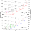 |
Fig. 1 Energy level diagram of NH3
showing the ground (v = 0;
lower half) and the first excited vibrational (v2 = 1;
upper half) states. The truncated vertical axes on the left and right show the energy from the ground
(E∕k;
K) and the corresponding wavenumber ( |

3 Observations
We observed various NH3 transitions in four oxygen-rich stars of different evolutionary stages: IK Tau, a long-period variable (LPV) with a high mass-loss rate; OH 231.8+4.2, a bipolar pre-planetary nebula (PPN) around an OH/IR star; VY CMa, a red supergiant (RSG); and IRC +10420, a yellow hypergiant (YHG). These targets sample both the low-/intermediate-mass (LPV/PPN) and the high-mass (RSG/YHG) regimes of post-main sequence stellar evolution. They are also among the most chemically rich and the most studied objects of their classes. All four targets exhibited strong NH3 emission in previous observations (e.g. Menten & Alcolea 1995; Menten et al. 2010).
In the following subsections, we discuss the multi-wavelength observations of NH3 emission and absorption in the CSEs of these four targets. For an overview, Table 1 lists all the radio inversion and (sub)millimetre rotational lines and Table 2 lists all the MIR vibrational transitions that are included in our study.
List of MIR NH3 ν2 transitions searched with the TEXES instrument at the NASA IRTF under the programme 2016B064 and their previous detection in evolved stars.
3.1 Radio inversion transitions
Table A.1 summarises all the relevant VLA observations and the corresponding spectral setups in this study. The two ground-state metastable inversion transitions of NH3, (J, K) = (1, 1) and (2, 2), were observed with the NRAO3 VLA in 2004 for IK Tau and IRC +10420 (legacy ID: AM797). The observations were performed in the D configuration, which is the most compact one, with the correlator in the 2AD mode. The two inversion lines were observed at their sky frequencies simultaneously in individual IF channels of different circular polarisations. Polarisations are irrelevant in our analysis. The total bandwidth of each IF channel is 12.5 MHz (~ 160 km s−1) with a spectral resolution of 390.625 kHz (~ 5 km s−1).
The absolute flux calibrators during the observations of IK Tau and IRC +10420 were 3C 48 (J0137+3309) and 3C 286 (J1331+3030), respectively. Based on the time-dependent coefficients determined by Perley & Butler (2013), the flux densities of 3C 48 and 3C 286 during the observations were 1.10 Jy and 2.41 Jy, respectively. The interferometer phase of IK Tau was referenced to the gain calibrator J0409+1217 and that of IRC +10420 was referenced to J1922+1530. Both calibrators are about 4° from the respective targets.
The inversion spectra of both stars have been published by Menten et al. (2010). In this study, we repeated the data reduction and radiative transfer modelling of the same VLA dataset. The data were reduced by the Astronomical Image Processing System (AIPS; version 31DEC14). Part of the observations of IK Tau suffered from poor phase stability, probably due to bad weather, so the later half of the observation (time ranging between 16:15:00 and 19:16:00) had to be discarded. The rest of the calibration and imaging were done in the standard manner. We imaged the data with the CLEAN algorithm under natural weighting to minimise the rms noise and restored the final images with a circular beam of 3.″7 in full width at half maximum (FWHM), which is approximately the geometric mean of the FWHMs of the major and minor axes of the raw beam.
With the new wideband correlator, WIDAR4, the upgraded VLA can cover multiple NH3 inversion lines simultaneously in the radio K band, particularly around 22−25 GHz. We performed three 2 GHz K-band surveys towards VY CMa, OH 231.8+4.2, and IK Tau with different array configurations and frequency coverages. VY CMaand OH 231.8+4.2 were observed on 2013 April 05 in the D configuration under the project VLA/13A-325. The correlator was tuned to cover the six lowest metastable transitions from (1, 1) to (6, 6). 3C 147 (J0542+498) was observed as the absolute flux calibrator, J0731-2341 and J0748-1639 were observed as the gain (relative amplitude and phase) calibrators of VY CMa and OH 231.8+4.2, respectively. We used CASA5 version 4.2.2 to manually calibrate and image the dataset (McMullin et al. 2007). Spectral line calibration and continuum subtraction were performed in the standard manner similar to that presented in the CASA tutorial6 . For both targets, we used natural weighting to image all six inversion lines. The rms noise in each channel map (ΔV = 3 km s−1) is roughly 0.8 mJy beam−1 and the restoring beam is about 4″ in FWHM. We also tried imaging under uniform weighting with a beam of ~ 3″ , but the NH3 emission was still not clearly resolved. We restored all the images with a common circular beam of 4.″0, which is the upper limit of the geometric means of the FWHMs of the major and minor axes of the raw beam of the six transitions.
IK Tauwas also observed in 2015 and 2016 with D, C, and B configurations with baselines ranging from 35 m to ~ 11 km under the projects VLA/15B-167 and VLA/16A-011. The absolute flux (3C 48) and gain calibrators (J0409+1217) were the same as in the 2004 observations. We conducted the line surveys at lower frequencies to search for non-metastable NH3 emission and to cover the strong water masers near 22.235 GHz. The highest covered metastable line is NH3 (4, 4) (see Table A.1). All data were processed in CASA version 4.6.0. For each day of observations, we first performed standard phase-referenced calibration, then used the strong H2 O maser to self-calibrate the science target7. The last observation of IK Tau on 2016 July 01 suffered from very poor phase stability and the rms noises of the visibility data were at least ten times higher than for any other observation. This dataset is therefore excluded from our imaging and analysis. All other visibility data of the metastable lines (from (1, 1) to (4, 4)) were then continuum subtracted, concatenated, and imaged using natural weighting. The images were restored with a common, circular beam with a FWHM of 0.″45. For better visualisation, we further smoothed the images with a 0.″7-FWHM Gaussian kernel and the resultant beam has a FWHM of 0.″83.
The continuum data of the ~2 GHz windows of IK Tau, VY CMa, and OH 231.8+4.2 were also imaged in the similar manner. The images were fitted with a single Gaussian component. Table A.2 presents the results of the continuum measurements of the three targets.
3.2 Submillimetre rotational transitions
NH3 rotational transitions were observed with the HIFI8 instrument aboard the ESA Herschel Space Observatory (Pilbratt et al. 2010). The detection of the lowest rotational line, JK = 10–00, towards three O-rich targets (except OH 231.8+4.2) in our study has already been reported and analysed by Menten et al. (2010) using spectra exclusively from the Herschel Guaranteed Time Key Programme HIFISTARS (Bujarrabal et al. 2011). After the successful detection of the 10 –00 line, follow-up observations were carried out to cover higher transitions, that is, J = 2–1 and J = 3–2. In addition to the HIFISTARS data, we also include the data of all available NH3 rotational transitions of our targets in the Herschel Science Archive (HSA; v8.0)9 to extend the coverage of NH3 transitions and to improve the signal-to-noise (S/N) ratio of the transitions covered by HIFISTARS.
Table B.1 summarises the HIFI spectra, which are all double sideband (DSB) spectra, used in this study. All but one observation were carried out in dual beam switch (DBS) mode. In DBS mode, ON-OFF subtraction is done twice by first chopping the HIFI beam between the science target and an emission-free reference with one being the ON position and the other being OFF, and then swapping the ON/OFF roles of the target and reference positions (Sect. 8.1.1 of de Graauw et al. 2010). This method helps reducing the baseline ripple caused by standing waves. The spectrum with the Observation ID (OBSID) of 1342190840 was taken in frequency switch mode, which results in significant baseline ripple. However, the frequency range of the NH3 JK = 10–00 line is small compared to that of the ripple and the S/N ratio of the line is quite high, allowing decent baseline removal.
Since there are no User Provided Data Products (UPDPs) for the observations other than those of HIFISTARS, we use the pipeline-processed products of all data, including those from HIFISTARS observations, to ensure uniform data processing among the spectra. We downloaded the Level 2 data products from the HSA via the Herschel Interactive Processing Environment (HIPE; v15.0.0) software (Ott 2010). All products have been processed with the Herschel Standard Product Generation (SPG) pipeline (v14.1.0) during the final bulk reprocessing of the HSA. Apart from the flux differences caused by the adopted main-beam efficiencies as discussed below, there are no significant differences between the UPDPs and pipeline products of the HIFISTARS observations.
For each data product, we averaged the signals from the H and V polarisation channels and stitched the spectrometer subbands together. The spectra in antenna temperature ( ) scale were then exported to FITS format by the hiClass task and loaded in CLASS10 of the GILDAS package11 (Pety 2005), where further processing including polynomial baseline removal, main-beam efficiency correction, and noise-weighted averaging ofspectra from different observations were carried out.
The antenna temperature scale of the spectra was converted to main-beam temperature (Tmb) by the relation
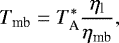 (1)
(1)
where ηl = 0.96 is the forward efficiency (Roelfsema et al. 2012) and ηmb is the main-beam efficiency. The main-beam efficiency for each NH3 line frequency is the average of ηmb, H and ηmb, V for both polarisations, which are evaluated from the parameters reported by Mueller et al. (2014) in October 2014. Their ηmb values are consistently smaller (by 10−20%) than and supersede those reported by Roelfsema et al. (2012) assuming Gaussian beam shape. Previous publications that include some of our NH3 spectra were based on the old ηmb values (e.g. Menten et al. 2010; Bujarrabal et al. 2012; Justtanont et al. 2012; Teyssier et al. 2012; Alcolea et al. 2013).
By combining the calibration uncertainty budget in Roelfsema et al. (2012) in quadrature, we estimate the calibration uncertainties to be about 10% for NH3 J = 1–0 (band 1) and 15% for J = 2–1 and J = 3–2 (bands 5 and 7). The sizes of the NH3-emitting regions of our targets as constrained by VLA observations are ≲ 4″ , much smaller than the FWHM of the telescope beam, which ranges from about 12″ (J = 3–2) to 37″ (J = 1–0).
3.3 Millimetre rotational transition within the v2 =1 state
We searched for the JK = 21–11 rotational transition within the vibrationally excited state v2 = 1 at 140.142 GHz (2.14 mm) from IK Tauwith the IRAM12 30m Telescope on Pico Veleta. The frequency range of interest was covered by an earlier line survey (IRAM projects 216-09 and 212-10; PI: C. Sánchez Contreras), which has subsequently been published by Velilla Prieto et al. (2016, 2017), and no NH3 line was detected at the rms noise in Tmb scale of 1.8 mK at the velocity resolution of 4.3 km s−1. In order to obtain a tighter constraint, we conducted a deep integration at the frequency of the 2 mm rotational line in August 2015 under the project 052-15.
We observed IK Tau with the Eight MIxer Receiver (EMIR) in the 2 mm (E150) band (Carter et al. 2012). ON-OFF subtraction was done with the wobbler switching mode with a throw of ± 120″. Pointing was checked regularly every ~1 h with Uranus or a nearby quasar (J0224+0659 or J0339-0146, selected by a compromise between angular distance and 2 mm flux density), and focus was checked with Uranus every ~ 3 h and after sunrise. The total ON-source integration time is about 10.1 h. The data were calibrated with the MIRA13 software in GILDAS. We adopt the main-beam and forward efficiencies to be ηmb = 0.74 and ηl = 0.93, respectively, which are the characteristic values at 145 GHz (Kramer et al. 2013). The rms noise near 140 GHz in Tmb scale is 0.61 mK at the velocity resolution of 5.0 km s−1. By comparing the line detection from other molecules, our spectrum is consistent with that presented by Velilla Prieto et al. (2017) within the noise.
3.4 Mid-infrared rovibrational transitions
The ν2 band (v2 = 1 ← 0) of ammonia absorbs MIR N-band radiation from the central star and its circumstellar dust shells. Previous observations have detected multiple NH3 absorption lines from the carbon star IRC +10216 and a few O-rich (super)giants (see Table 2). The highest spectral resolutions were achieved by the Berkeley infrared heterodyne receiver at the then McMath Solar Telescope of Kitt Peak National Observatory14 (Betz 1975) and the MPE15 10-micron heterodyne receivers at various telescopes (Schrey et al. 1985; Rothermel et al. 1986) with a resolving power of R = λ∕Δλ ≈ 1–6 × 10⁶. Other old MIR observations made use of the Berkeley heterodyne receiver at the Infrared Spatial Interferometer (Monnier et al. 2000c) and the Fourier Transform Spectrometer at the Kitt Peak Mayall Telescope (Keady & Ridgway 1993) with R ~ 105.
In order to obtain a broader coverage of ν2 absorption lines from evolved stars, we performed new MIR observations of IK Tau, VY CMa, and the archetypal eponymous Mira variable o Cet with the Texas Echelon Cross Echelle Spectrograph (TEXES; Lacy et al. 2002) at the 3.0 m NASA IRTF16 under the programme 2016B064. The targets were observed on (UT) 2016 December 22 and 23 in high-resolution mode with a resolving power of R ~ 105 (Lacy et al. 2002). Each resolution element is sampled by 4 pixels and the width of each spectral pixel is about 0.003 cm −1. In this article, we present the spectra of IK Tau and VY CMa in three wavelength (wavenumber) settings near 10.3 (966), 10.5 (950) and 10.7 μm (930 cm −1), covering in total 14 rovibrational transitions as listed in Table 2. The width of the slit is 1.″4. The on-source time for each target in each setting was about 10 min and the total observing time per setting was about 3 h. The dwarf planet Ceres was observed as the telluric calibrator for the setting near 10.7 μm (930 cm −1) and the asteroid Vesta was observed for the rest.
The FWHM of the IRTF’s point-spread function in these settings is about 0.″9. The visual seeing during our observations was ≲ 1.″017, which corresponds to about 0.″6 at 10 μm (e.g. van den Ancker et al. 2016). Hence, our observations are diffraction-limited.
The data were processed with a procedure similar to the TEXES data reduction pipeline (Lacy et al. 2002), except that telluric lines were removed by a separate fitting routine. In the pipeline, the calibration frame (flat field) was the difference between the black chopper blade and sky measurements, Sν (black −sky), which partially removes telluric lines (see Eq. (3) of Lacy et al. 2002). In our processing, the data spectra were flat-fielded with the black measurements and the intermediate source intensity is given by
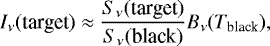 (2)
(2)
where Sν and Bν are the measured signal and the Planck’s law at the frequency ν. Each intermediate spectrum was then normalised and divided by a modelled telluric transmission spectrum. The parameters of the telluric transmission model were chosen to make the divided spectrum as flat as possible and to fit the observed Sν (black −sky), with the atmospheric temperatures and humidities constrained by weather balloon data. Finally, each target spectrum was divided by a residual spectrum smoothed with a Gaussian kernel of 60 km s−1 in FWHM. The last division was necessary to remove broad wiggles due to the echelon blaze function and interference fringes, but may also have removed or created broad wings on the observed circumstellar lines.
We verified the wavenumber scale of the calibrated data by comparing the minima of atmospheric transmission with the rest wavenumbers of strong telluric lines in the GEISA spectroscopic database18 (2015 edition; Jacquinet-Husson et al. 2016). Almost all strong telluric lines are identified as due to CO2, except for the H2O line at 948.262881 cm−1. The differences between the transmission minima and telluric lines do not exceed 4 km s−1 in radio local standard of rest (LSR) velocity. The uncertainties of the rest wavenumbers of our targeted NH3 lines (Table 2) correspond to velocities of <0.002 km s−1.
We converted the wavenumber (frequency) axis from topocentric to LSR frame of reference using the ephemeris software GILDAS/ASTRO19. In order to remove local wiggles in the normalised spectra of the targets, for IK Tau in particular, we performed polynomial baseline subtraction for some NH3 spectra in GILDAS/CLASS. The removal of telluric line contamination was not perfect. Hence, the residual baseline was not always stable within the possible width of the lines and for some spectra it was difficult to identify the continuum. Although the strong absorption features were not severely affected, any much weaker emission features (if they exist at all) may be lost.
We also compare the old aR(0, 0) and aQ(2, 2) spectra of VY CMaand the aR(0, 0) spectrum of IRC +10420 as detected with the Berkeley heterodyne receiver at the McMath Solar Telescope. These spectra were digitised from the scanned paper of McLaren & Betz (1980, © AAS. Reproduced with permission) with the online application WebPlotDigitizer20 (version 3.10; Rohatgi & Stanojevic 2016). We did not detect NH3 absorption from o Cet; therefore weonly briefly discuss its non-detection in Sect. 5.5.
4 Radiative transfer modelling
We modelled the NH3 spectra with the one-dimensional (1D) radiative transfer code RATRAN21 (version 1.97; Hogerheijde & van der Tak 2000), assuming that the distribution of NH3 is spherically symmetric. RATRAN solves the coupled level population and radiative transfer equations with the Monte Carlo method and produces an output image cube for each modelled transition. We then convolved the model image cubes with the same telescope point-spread function or restoring beam as that of the observed data. We processed the modelled images and spectra with the Miriad software package22 (Sault et al. 1995). We explain the molecular data files and input dust temperature profiles in the following subsections, and discuss the input physical models for each target in Sect. 5.
4.1 NH3 molecular data
4.1.1 Energy levels and radiative transitions
As discussed in Sect. 2, the energy levels of ortho- (K = 0, 3, 6, … ) and para-NH3 (K = 1, 2, 4, 5, …) are essentially independent and the two species have to be modelled separately. We obtained the molecular data files of ortho- and para-NH3 from Schmidt et al. (2016). The energy levels and transition line strengths were taken from the “BYTe” hot NH3 line list23 (Yurchenko et al. 2011). The data files for our modelling consist of all the energy levels up to the energy corresponding to 3300 cm −1 (or 4750 K) in the ground vibrational state and the v2 = 1 state. There are 172 energy levels (up to J = 15) and 1579 radiative transitions for ortho-NH3, and 340 levels and 4434 transitions for para-NH3.
4.1.2 Collisional rate coefficients
In the model of Schmidt et al. (2016), the collisional rate coefficients used for the ground vibrational state of NH3 were calculated by Danby et al. (1988) for the collisions with para-H2 (j = 0) at temperatures 15 K≤ Tkin ≤ 300 K and were extrapolated to higher temperature assuming that they are proportional to  , where Tkin is the kinetic temperatureof para-H2. These rate coefficients were computed in the transitions involving energy levels up to Jortho = 6 (Eup∕k < 600 K) for ortho-NH3 and Jpara = 5 (Eup∕k < 450 K) for para-NH3. Hence, higher energy levels are populated via radiative transitions only. By adopting some constant rate coefficients for other transitions, Schmidt et al. (2016) found that the collisional transitions involving higher ground-state levels or vibrationally excited levels were not important.
Bouhafs et al. (2017) reported new calculations on the rate coefficients of the collisions between NH3 and atomic hydrogen (H), ortho-H2, and para-H2 at temperatures up to 200 K and in transitions involving energy levels up to Eup∕k = 600 K (Jortho ≤ 6 and Jpara ≤ 7). Their calculations were based on the full-dimensional (9D) NH3–H potential energy surface (PES) of Li & Guo (2014) and the five-dimensional (5D) NH3–H2 PES of Maret et al. (2009) with an ad hoc approximation of the inversion wave functions using the method of Green (1976). The rate coefficients of NH3–para-H2 are thermalised over j = 0 and 2 and they are consistent with those of Danby et al. (1988) within a factor of 2. We do not consider the collisions with H in our models. The coefficients of NH3 with ortho- and para-H2 at 200 K are consistent within a factor of ~ 2 (up to 4). We weight the coefficients of the two H2 species by assuming a thermal H2 ortho-to-para ratio of 3 (Flower & Watt 1984). Since the coefficients for most low-J and small-ΔJ transitions do not vary much with temperature (e.g. Fig. 2 of Bouhafs et al. 2017), we apply constant extrapolation of the coefficients from 200 K to higher temperatures. Vibrations were not included in the 5D PES of NH3–H2. Quantum dynamics calculations have shown that vibrationally elastic (Δv = 0; purely rotational) excitation of linear molecules by collisions with noble gases (e.g. helium) is almost independent of the vibrational state v (Roueff & Lique 2013; Balança & Dayou 2017, and references therein). This also appears to be valid in the elastic (Δv2 = 0) transitions of the H2 O–H2 collision system (Faure & Josselin 2008); therefore, we assume the elastic (rotation-inversion) transitions within the v2 = 1 state to have the same rate coefficients as the “corresponding elastic transitions”24 within the ground state. For vibrationally inelastic transitions (v2 = 1 → 0), we scale the coefficients of the “corresponding elastic transitions” within the ground state by a constant factor of 0.05 (Faure 2017, priv. comm.; Faure & Josselin 2008), taking detailed balance into account. For all other transitions, that is, vibrationally elastic (within v2 = 1) or inelastic (v2 = 1 → 0) transitions that do not have a “corresponding elastic transition” within the ground vibrational state, we adopt a constant rate coefficient of 2 × 10⁻¹¹ cm3 s−1 for vibrationally elastic transitions and 1 × 10⁻¹² cm3 s−1 for vibrationally inelastic transitions.
Our extrapolations in temperature and rovibrational transition are admittedly quite crude but they are necessary to make. Similar to the analysis of Schmidt et al. (2016, their Sect. 3), we compare the synthesised spectra of the transitions discussed in this article using the above-mentioned extended coefficients with those using only the coefficients of either Danby et al. (1988) or Bouhafs et al. (2017). Neglecting collisional transitions of high-J and v2 -excited levels, the coefficients of Danby et al. (1988) and Bouhafs et al. (2017) do not produce qualitatively different spectra. While the spectra of IK Tau are insensitive to the presence of the extended rate coefficients, those of the other targets are noticeably affected, especially in the rotational transitions (< 50% in the peak intensity). Future quantum dynamics calculations, which require a full-dimensional (12D) PES of NH3–H2, are necessary to determine the complete set of rate coefficients for circumstellar NH3 modelling.
4.2 Dust continuum emission
The thermal continuum emission from dust is related to the emission and absorption coefficients. In RATRAN, the absorption coefficient is given by
 (3)
(3)
where u is the atomic mass unit, d/g is the dust-to-gas mass ratio, and  is the number density of molecular H2 (Hogerheijde & van der Tak 2000). The code assumes that the gas consists of 80% H2 and 20% Heby number. The emission coefficient can then be computed with the knowledge of the dust temperature, Tdust,
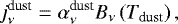 (4)
(4)
where Bν(T) is the Planck function.
We produce the dust temperature profiles of IK Tau, VY CMa, and IRC +10420 by modelling their spectral energy distributions (SEDs) with the continuum radiative transfer code DUSTY (Ivezić et al. 1999). We constrain the MIR fluxes of IK Tau by the IRAS25 Low Resolution Spectra corrected by Volk & Cohen (1989) and Cohen et al. (1992) and those of VY CMa and IRC +10420 by the ISO26 SWS27 data processed by Sloan et al. (2003). The FIR fluxes of these three stars are constrained by the ISO LWS28 data processed by Lloyd et al. (2013).
We only modelled the SEDs with cool oxygen-rich interstellar silicates of which the optical constants were computed by Ossenkopf et al. (1992). The comparison of Suh (1999) shows that the opacity functions and optical constants of the cool silicates from Ossenkopf et al. (1992) are consistent with those of other silicates in the literature. The optical constants of silicates mainly depend on the contents of magnesium and iron in the assumed chemical composition (Dorschner et al. 1995). The dust emissivity function (and hence the dust opacity, κν ) of cool silicates from Ossenkopf et al. (1992) are readily available in the RATRAN package, therefore allowing us to employ a dust temperature profile that describes the SED self-consistently. Our SED models are primarily based on that presented in Maercker et al. (2008, 2016) for IK Tau and those in Shenoy et al. (2016) for VY CMa and IRC +10420. The derived dust temperature profiles of IK Tau and IRC +10420 agree very well with the optically thin model for dust temperature (Sopka et al. 1985),
 (5)
(5)
where p has a typical value of 1 (Olofsson 2003).
MIR images of OH 231.8+4.2 by Lagadec et al. (2011) have revealed a bright, compact core and an extended halo around the star. The MIR-emitting circumstellar material is dusty (Jura et al. 2002; Matsuura et al. 2006). The MIR emission of OH 231.8+4.2 near the wavelengths of silicate bands extends to FWHM sizes of 2.″6 × 4.″3 at 9.7 μm and 5.″4 × 9.″9 at 18.1 μm (Lagadec et al. 2011), covering most if not all of the NH3-emitting region. Juraet al. (2002) were able to explain the MIR emission from the compact core at 11.7 μm and 17.9 μm by an opaque, flared disc with an outer radius of 0.″25 and outer temperature of 130 K. This temperature is about 45% of that expected from the optically thin dust temperature model as shown in Eq. (5). For simplicity, therefore, we scale Eq. (5) by a factor of 0.45 and adopt p = 1 as the dust temperature profile of OH 231.8+4.2 in the NH3-emitting region, which is beyond the opaque disc model of Jura et al. (2002).
5 Results and discussion
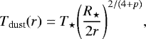
With the VLA, we detect all covered metastable (J = K) inversion transitions from all four targets, including (J, K) = (1, 1) to (4, 4) for IK Tau, (1, 1) to (6, 6) for VY CMa and OH 231.8+4.2, and (1, 1) and (2, 2) for IRC +10420. However, no non-metastable inversion emission from IK Tau is securely detected. Ground-state rotational line emission is also detected in all available Herschel/HIFI spectra. These include up to J = 3–2 towards IK Tau, VY CMa, and OH 231.8+4.2; and up to J = 2–1 towards IRC +10420. We do not detect the 140 GHz rotational transition in the v2 = 1 state towards IK Tau from the IRAM 30m observations. In the MIR spectra, all 14 rovibrational transitions from IK Tau and 12 unblended transitions from VY CMa are detected in absorption. Figure 2 shows the full IRTF spectra of both stars in three wavelength settings. There are no strong emission components in these spectra. We note that, however, the spectra are susceptible to imperfect telluric line removal and baseline subtraction as mentioned in Sect. 3.4.
In Sects. 5.1–5.4, we discuss the observational and modelling results for each target separately; in Sect. 5.5, we summarise the modelling results and discuss the possible origin of circumstellar ammonia. We made use of the IPython shell29 (version 5.1.0; Pérez & Granger 2007) and the Python libraries including NumPy30 (version 1.11.2; van der Walt et al. 2011), SciPy31 (version 0.18.1; Jones et al. 2001), matplotlib32 (version 1.5.3; Hunter 2007; Matplotlib Developers 2016), and Astropy33 (version 1.3; Astropy Collaboration et al. 2013) in computing and plotting the results in this article.
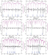 |
Fig. 2 NASA IRTF/TEXES spectra (in black) of IK Tau (left) and VY CMa (right) near the wavelengths (wavenumbers) of 10.7 μm (930 cm −1 ; top), 10.5 μm (950 cm −1 ; middle), and10.3 μm (966 cm −1 ; bottom). The wavenumber axes are in the topocentric frame of reference. The target spectra are normalised and zoomed. The normalised calibrator spectra are plotted in magenta and the fractional atmospheric transmissions are shown in grey. Only the target data with atmospheric transmission greater than 0.8 are plotted. The dark blue dotted lines in each spectrum indicate the positions of the labelled NH3 rovibrational transitions in the stellar rest frame and the green solid lines indicatethe telluric lines (in the observatory frame) that blend with the NH3 lines of VY CMa. We assume the systemic velocities of IK Tau and VY CMa to be 34 km s −1 and 22 km s−1, respectively. |
5.1 IK Tau
5.1.1 VLA observations of IK Tau
Figure 3 shows the integrated intensity maps of all four metastable inversion lines (J = K) over the LSR velocity range 34 ± 21 km s−1. These images combined the data from our 2016 observations with the B and C arrays of the VLA. The native resolution was about 0.″45 in FWHM and we smoothed the images to the final resolution of 0.″83 for better visualisation. NH3 emission is detected at rather low S/N (≲6). The imagesfrom the D-array observations in 2004 do not resolve the NH3 emission and are not presented. Figure 4 shows the flux density spectra, integrated over the regions specified in the vertical axes, of all VLA observations.
Comparing the NH3 (1, 1) (top row) and (2, 2) (middle row) spectra taken at two epochs, the (1, 1) line emission in 2004 was predominantly in the redshifted velocities while that in 2016 was mainly blueshifted. This may indicate temporal variations in the NH3 emission at certain LSR velocities, but is not conclusive because of the low S/N of the spectra. The total fluxes of the 2004 spectra within a 10″ × 10″ box are consistent with those of the 2016 spectra within a 2″-radius aperture centred at the stellar radio continuum. Hence, most of the NH3 inversion line emission is confined within a radius of ~2″. In the full-resolution images, the strongest emission is generally concentrated within ~ 0.″7 from the star – but not exactly at the continuum position – and appears to be very clumpy. Individual channel maps show localised, outlying emission up to ~2″ from the centre.
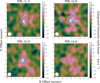 |
Fig. 3 Integrated intensity maps of the four lowest NH3 inversion lines from IK Tau as observed with the VLA in B and C configurations over the LSR velocity range of [13, 55] km s−1 (relative velocity between ±21 km s−1 to the systemic). Horizontal and vertical axes represent the offsets (arcsec) relative to the fitted centre of the continuum in the directions of right ascension and declination, respectively. The circular restoring beam of 0.″83 is indicated in the bottom-left corner of each map. The contour levels for the NH3 lines are drawn at 3, 4, 5, 6σ, where σ = 5.4 mJy beam−1 km s−1. |
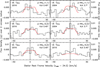 |
Fig. 4 NH3 inversion line spectra of IK Tau. Black lines show the VLA spectra in flux density and red lines show the modelled spectra. NH3 (1, 1) and(2, 2) were observed in 2004 (top right and middle right) with D configuration and 2016 (top left and middle left) with both B and C configurations. The 2004 spectra were integrated over a 10″ × 10″ box and the 2016 spectra were integrated over a 2″-radius circle. |
5.1.2 Herschel/HIFI observations of IK Tau
The Herschel/HIFI spectra of IK Tau are shown in Fig. 5. Except for the blended transitions JK = 30–20 and 31 –21, the rotational spectra appear to be generally symmetric with a weak blueshifted wing near the relative velocity between − 21 and − 16 km s−1 from the systemic. This weakness of the blueshifted wing may be a result of weak self-absorption. The central part of the profiles within the relative velocity of ± 10 km s−1 is relatively flat. Since the NH3-emitting region is unresolved within the Herschel/HIFI beams, the flat-topped spectra suggest that the emission only has a small or modest optical thickness. In the high-S/N spectrum of 10 –00, the central part also shows numerous small bumps, suggesting the presence of substructures of various kinematics in the NH3-emitting regions. Since the line widths of NH3 spectra resemble those from other major molecular species (e.g. CO, HCN; Decin et al. 2010b), the bulk of NH3 emission comes from the fully accelerated wind in the outer CSE with a maximum expansion velocity of 17.7 km s−1 (Decin et al. 2010b).
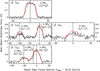 |
Fig. 5 NH3 rotational line spectra of IK Tau. Black lines show the observed spectra from Herschel/HIFI and red lines show the modelled spectra. |
5.1.3 IRAM observations of IK Tau
We did not detect the rotational transition v2 = 1 JK = 21–11 near 140 GHz within the uncertainty of 0.61 mK per 5.0 km s−1. If we assume the line-emitting region of this transition is also located in the fully accelerated wind with an expansion velocity of Vexp = 17.7 km s−1, as for the ground-state rotational transitions, then the rms noise of the velocity-integrated spectrum would be ~ 0.24 mK (over 35.4 km s−1) in Tmb.
Our observations repeated the detection of PN near 141.0 GHz (De Beck et al. 2013) and H2 CO near 150.5 GHz (Velilla Prieto et al. 2017) at higher S/N. We also detected NO near 150.18 and 150.55 GHz that were not reported in Velilla Prieto et al. (2017), in which the higher NO transitions near 250.5 GHz were detected. In the context of circumstellar environments and stellar merger remnants, NO has only been detected elsewhere towards IRC +10420 (Quintana-Lacaci et al. 2013), OH 231.8+4.2 (Velilla Prieto et al. 2015), and CK Vulpeculae (Nova Vul 1670; Kamiński et al. 2017)thus far.
5.1.4 IRTF observations of IK Tau
Figure 2 shows the normalised IRTF spectra of IK Tau in three wavelength settings prior to baseline subtraction. All 14 targeted NH3 rovibrational transitions are clearly detected in absorption. Figures 6–8 present the baseline-subtracted spectra in the stellar rest frame. The maximum absorption of all MIR transitions appear near the LSR velocities in the range of 16–17 km s−1, which corresponds to the blueshifted velocity between − 18 and − 17 km s−1 and is consistent with the terminal expansion velocity of 17.7 km s−1 as determined by Decin et al. (2010b). Blueshifted absorption near terminal velocity is consistent with the scenario that the NH3-absorbing gas is moving towards us in the fully accelerated outflow in front of the background MIR continuum.
The MIR NH3 absorption in IK Tau cannot come from the inner wind. First of all, our SED modelling (Sect. 4.2) shows that the optical depth of the circumstellar dust is about 1.3 at 11 μm. Continuum emission from dust grains would probably fill the line absorption near 10.5 μm had it originated beneath the dust shells. Furthermore, the visual phase of IK Tau in our IRTF observations is about 0.35, which is based on our recalculations of its visual light curve using modern photometric data (see Fig. C.2). Mira variables at this phase, including IK Tau (Hinkle et al. 1997), show CO second overtone (Δv= 3) absorption, which samples the deep pulsating layers down to ~1 R⋆, close to the stellar systemic velocity or in the redshifted (infall) velocities (Lebzelter & Hinkle 2002; Nowotny et al. 2010; Liljegren et al. 2017). If NH3 was produced in high abundance close to the stellar surface, we would see the absorption features in much redder (more positive) velocities; if it was abundant at the distance of a few stellar radii from the star, the observed velocity blueshifted by about 18 km s−1 from the systemic would be too high for the gas in the inner wind of Mira variables (e.g. Höfner et al. 2016; Wong et al. 2016). As a result, we only consider NH3 in the dust-accelerated regions of the CSE in our subsequent modelling (Sect. 5.1.5) even though we cannot exclude the presence of NH3 gas in the inner wind based on the available MIR spectra.
Amongthe same series of rotationally elastic transitions (aQ or sQ), the absorption profiles are slightly broader in higher-J transitions. For NH3, the thermal component of the line broadening is below 1 km s−1 when  is lower than 1000 K, so the observed line widths of several up to ~10 km s−1 are mainly contributed by the microturbulent velocity of the circumstellar gas. This suggests that the higher-J levels are more readily populated in more turbulent parts of the CSE.
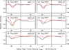 |
Fig. 6 Q-branch NH3 rovibrational spectra of IK Tau. These transitions connect the lower energy levels of the ground-state inversion doublets and the upper levels in the vibrationally excited state. Black lines show the observed spectra from the NASA IRTF and red lines show the modelled spectra. Each modelled spectrum was divided by a smoothed version of itself as in the real data (see Sect. 3.4) in order to induce the similar distortion in the line wings. |
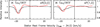 |
Fig. 7 NH3 rovibrational spectra of IK Tau in the transitions aR(0, 0) and sP(1, 0). Black lines show the observed spectra from the NASA IRTF and red lines show the modelled spectra. Each modelled spectrum was divided by a smoothed version of itself as in the real data (see Sect. 3.4) in order to induce the similar distortion in the line wings. |
5.1.5 NH3 model of IK Tau
Decin et al. (2010b) presented detailed non-LTE radiative transfer analysis of molecular line emission from the CSE of IK Tau. In particular, the gas density and thermodynamic structure, including the gas kinetic temperature and expansion velocity, of the CSE have been constrained by modelling multiple CO and HCN spectra observed by single-dish telescopes. Therefore, we adopt the same density, kinetic temperature and expansion velocity profiles as in model 3 of Decin et al. (2010b). The gas density of the CSE is given by the conservation of mass in a uniformly expanding outflow,
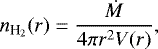 (6)
(6)
where Ṁ = 8 × 10⁻⁶ M⊙ yr−1 is the average gas mass-loss rate, and V (r) is the expansion velocity at radius r. We use the classical β-law to describe the radial velocity field, that is,
 (7)
(7)
where Vin = 3 km s−1 is the inner wind velocity, Vexp = 17.7 km s−1 is the terminal expansion velocity, Rwind = 12 R⋆ is the radius from which wind acceleration begins, and β = 1 (Decin et al. 2010b).
The gas kinetic temperature is described by two power laws which approximate the profile computed from the energy balance equation (Decin et al. 2010b),
 (8)
(8)
where
 (9)
(9)
We parametrise the radial distribution of NH3 abundance with a Gaussian function, that is,
![Mathematical equation: \begin{equation*} \displaystyle f(r) = f_0 \exp\left[-\left(\frac{r}{\refd}\right)^{2}\right] \quad \text{if \begin{inlinestripns}{si479}$r > \rin$](/articles/aa/full_html/2018/04/aa31873-17/aa31873-17-eq16.png) (10)
(10)
where f(r) and f0 are the fractional abundance of NH3 relative to H2 at radius r and at its maximum value, respectively; Re is the e-folding radius at which the NH3 abundance drops to 1∕e of the maximum value presumably due to photodissociation. We did not parametrise the formation of NH3 in the inner CSE with a smoothly increasing function of radius. Instead, we introduce an inner radius, R in, for the distribution of NH3 at which its abundance increases sharply from the “default” value of 10−12 to the maximum. We assume the dust-to-gas mass ratio to be d/g = 0.002, a value typical for IK Tau and also AGB stars in general (e.g. Gobrecht et al. 2016). In order to reproduce the broad IRTF rovibrational spectra (Sect. 5.1.4), we have to adopt a high Doppler-b parameter of bDopp = 4 km s−1.
We are able to fit the spectra with Rin = 75 R⋆ = 0.″3, R e = 600 R⋆ = 2.″3, and f0 = 6 × 10⁻⁷. Both choices of Rin and Re are motivated by the inner and outer radii of the observed inversion line emission from the VLA images (Sect. 5.1.1). We note, however, that a smaller Re (~ 500 R⋆ = 1.″9) and a higher f0 (~ 7 × 10⁻⁷) can also reproduce fits of similar quality to the available spectra. On the other hand, a very small Re would reduce the line intensity ratios between higher and lower rotational transitions because the lower transitions come from the outer part of the NH3 distribution.
The inner radius is not tightly constrained because the small volume of the line-emitting region only contributes to a relatively small fraction of the emission. Although the predicted intensities of the rotational transitions within the v2 = 1 state (near 140.1 and 466.2 GHz) are sensitive to the adopted value of Rin in our test models, they are very weak compared to the noise levels achievable by (sub)millimetre telescopes with the typical amount of observing time. In the presented model of IK Tau, the peak brightness temperature of the v2 = 1 JK = 21–11 transition is ~0.03 mK, much lower than the rms noise of our observation (Sect. 5.1.3). High rotational transitions from J = 4–3 (~ 125μm; 2.4 THz) up to J = 9–8 (~ 57μm; 5.3 THz) were covered by the Herschel/PACS34 instrument. Most of them were not detected except for J = 4–3. We did not include the PACS data35 in our detailed modelling because the spectral resolutions are too coarse for detailed analysis. The predicted total flux of the blended J = 4–3 lines by our model is consistent, within 30%, with the PACS spectra. In this study, we can only conclude that the inner boundary of the NH3 distribution is ≲100 R⋆. Figure 9 shows the radial profiles of the input density, abundance, dust and gas temperatures, and expansion velocity.
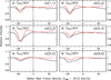 |
Fig. 8 Q-branch NH3 rovibrational spectra of IK Tau. These transitions connects the upper energy levels of the ground-state inversion doublets and the lower levels in the vibrationally excited state. Black lines show the observed spectra from the NASA IRTF and red lines show the modelled spectra. Each modelled spectrum was divided by a smoothed version of itself as in the real data (see Sect. 3.4) in order to induce the similar distortion in the line wings. |
 |
Fig. 9 Modelfor IK Tau. Left: input gas density and NH3 abundance profiles. Only the radii with abundance >10−10 are plotted. Middle: input gas and dust temperature profiles. Right: input expansion velocity profile. |
5.2 VY CMa
5.2.1 VLA observations of VY CMa
The radio inversion line emission from the CSE of VY CMa is not clearly resolved by the VLA beam of ~ 4″ . Figures 10 and 11 show the integrated intensity maps and flux density spectra, respectively, of all transitions covered in our VLA observation. The strongest emission is detected in NH3 (3, 3) and (2, 2), which also show somewhat extended emission up to ~ 4″ –6″ in the maps. Adopting the trigonometric parallax derived distance of 1.14 kpc (Choi et al. 2008, see also Zhang et al. 2012) and the stellar radius of 1420 R⊙ (Wittkowski et al. 2012), NH3 could maintain a moderate abundance out to ~700 R⋆ (4″ ).
A closeinspection on the maps reveals that the emission peaks at ≲ 1″ to the south-west from the centre of the radio continuum, which was determined by fitting the images combining all line-free channels near the NH3 spectra. This offset in peak molecular emission has also been observed under high angular resolution (~ 0.″9) with the Submillimeter Array (SMA) in multiple other molecules, including dense gas tracers such as CS, SO, SO2 , SiO, and HCN (Fig. 8 of Kamiński et al. 2013). Kamiński et al. (2013) noted that the spatial location of the peak emission may be associated with the “Southwest Clump” (SW Clump) as seen in the infrared images from the Hubble Space Telescope (HST; Smith et al. 2001; Humphreys et al. 2007). Since SW Clump was only seen in the infrared filter but not in any visible filters, Humphreys et al. (2007) suggested that the feature is very dusty and obscures all the visible light. However, submillimetre continuum emission from SW Clump has never been detected (Kamiński et al. 2013; O’Gorman et al. 2015), which cannot be explained by typical circumstellar grains with a small spectral emissivity index (O’Gorman et al. 2015). From K I spectra near 7700 Å, Humphreys et al. (2007) found that SW Clump is likely moving away from us with a small line-of-sight velocity of ~ 2.5 km s−1. Molecules from SW Clump, however, do not always emit from the same redshifted velocity. For example, the H2 S and CS emission appears over a wide range of velocities (Sect. 3.1.4 of Kamiński et al. 2013); TiO2 appears to emit in blueshifted velocities only (Fig. 2 of De Beck et al. 2015); NaCl emission peaks at the redshifted velocity of 3 kms−1 (Sect. 3.3 of Decin et al. 2016), similar to the velocity determined from the K I spectra. In our VLA images, we see the south-west offset of NH3 emission from much-higher-redshifted velocities between ~9 and 30 km s−1 relative to our adopted systemic LSR velocity (22 km s−1). The peak of the south-west emission is seen near 20–25 km s−1. If the peak NH3 emission is indeed associated with the infrared SW Clump, then NH3 may trace a distinct kinematic component in this possibly dusty and dense feature.
The spectra show relatively flat profiles, with two weakly distinguishable peaks near the LSR velocities of about − 5–0 km s−1 and 40–45 km s−1. These features correspond to the relative velocities of roughly − 25 km s−1 and 20 km s−1, respectively. As we show in the following subsection, the NH3 JK = 10(s)–00(a) rotational transition, but not the higher ones, also shows similar peaks in its high-S/N spectrum. Furthermore, high-spectral-resolution spectra of SO and SO2 also show prominent peaks near the same velocities of the NH3 features (e.g. Tenenbaum et al. 2010a; Fu et al. 2012; Adande et al. 2013; Kamiński et al. 2013).
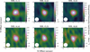 |
Fig. 10 Integrated intensity maps of the six lowest NH3 inversion lines from VY CMa as observed with the VLA over the LSR velocity range of [−17, 85] km s−1 (relative velocity between ±51 km s−1). Horizontal and vertical axes represent the offsets (arcsec) relative to the fitted centre of the continuum in the directions of right ascension and declination, respectively. The circular restoring beam of 4.″ 0 is indicated in the bottom-left corner of each map. The contour levels for the NH3 lines are drawn at: 3, 6, 9, 12, 15σ for (1, 1); 3, 6, 12, 18, 24σ for (2, 2) and(3, 3); 3, 6, 9, 12σ for (4, 4) to (6, 6), where σ = 14.2 mJy beam−1 km s−1. |
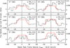 |
Fig. 11 NH3 inversion line spectra of VY CMa. Black lines show the VLA spectra in flux density and red lines show the modelled spectra. All transitions were observed in 2013 with D configuration. The spectra were integrated over an 8″ -radius circle. |
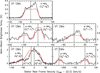 |
Fig. 12 NH3 rotational line spectra of VY CMa. Black lines show the observed spectra from Herschel/HIFI and red lines show the modelled spectra. |
5.2.2 Herschel/HIFI observations of VY CMa
Figure 12 shows all rotational spectra of VY CMa. The NH3 rotational transitions JK = 10(s)–00(a) and JK = 3K(s)–2K(a) (K = 0, 1, 2) observed under the HIFISTARS Programme have already been published by Menten et al. (2010) and Alcolea et al. (2013). Other transitions were covered in the spectral line survey of the proposal ID “OT1_jcernich_5” (PI: J. Cernicharo). VY CMais the only target in this study with complete coverage of ground-state rotational transitions up to Jup = 3.
The full width (at zero power) of the NH3 10 (s )–00(a) and 20 (a )–10(s) spectra spans the relative velocity range of almost ±50 km s−1. The expansion velocity of the CSE of VY CMa is about 35 km s−1 (Decin et al. 2006); and therefore the expected total line width should not exceed 70 km s−1 if the NH3 emission arises from a single, uniformly expanding component of the circumstellar wind. Huge line widths have also been observed in other abundant molecules (e.g. CO, SiO, H2O, HCN, CN, SO, and SO2; Tenenbaum et al. 2010a,b; Alcolea et al. 2013; Kamiński et al. 2013). Some of the optically thin transitions even show multiple peaks in the spectra (e.g. Fig. 7 of Kamiński et al. 2013), suggesting the presence of multiple kinematic components moving at various line-of-sight velocities.
As already discussed by Alcolea et al. (2013, their Sect. 3.3.1), the line profiles of 10 (s )–00(a) and 30 (s )–20(a) are distinctly different, with the former showing significantly stronger emission in the redshifted velocities and the latter showing only one main component at the centre. With the new spectra, which show profiles that are somewhat intermediate between the two extremes, we find that the line shapes mainly depend on the relative intensities between the central component and the redshifted component near + 20–21 km s−1 relative to the systemic velocity. The redshifted component is stronger than the central in lower transitions, such as 10 (s )–00(a) and 21 (s )–11(a), but becomes weaker and less noticeable in higher transitions. The peak velocity of this redshifted component is also consistent with that of the south-west offset structure as seen in our VLA images, especially in NH3 (2, 2) and (3, 3). Therefore, at least part of the enhanced redshifted emission may originate from the local NH3-emitting region to the south-west of the star.
The 10 (s )–00(a) spectrum, which has the highest S/N, shows five peaks at the relative velocities of approximately − 25, − 11, 1, 13, and 21 km s−1. Similar spectra showing multiple emission peaks are also seen in CO, SO, and SO2 (e.g. Muller et al. 2007; Ziurys et al. 2007; Tenenbaum et al. 2010a; Fu et al. 2012; Adande et al. 2013; Kamiński et al. 2013). The most prominent peaks in these molecules occur at LSR velocities of − 7, 20–25, and 42 km s−1, corresponding to the relative velocities of − 29, − 2– + 3, and + 20 km s−1, respectively.High-angular-resolution SMA images and position-velocity diagrams of these molecules show complex geometry and kinematics of the emission; accordingly, dense and localised structures were introduced to explain individual velocity components (Muller et al. 2007; Fu et al. 2012; Kamiński et al. 2013). Except for the high-spectral-resolution spectrum of SO JN = 76–65, which also shows a peak near the relative velocity of 12 km s−1 (Fig. 6 in Tenenbaum et al. 2010a), no other molecules seem to exhibit the same peaks at intermediate relative velocities ( − 11 and 13 km s−1) as in NH3.
The NH3 inversion (Sect. 5.2.1) and rotational lines show spectral features at similar velocities to the SO and SO2 lines, suggesting that all these molecules may share similar kinematics and spatial distribution. High-angular-resolution SMA images show that SO and SO2 emission is extended by about 2–3″ (Fig. 8 of Kamiński et al. 2013). Hence, the strongest NH3 emission is likely concentrated within a radius of ~2″.
High rotational transitions including J = 4–3 (~ 125μm) and, possibly, J = 6–5 (~ 84μm) have been detected by Royer et al. (2010) with Herschel/PACS. However, line confusion from other molecular species (e.g. H2 O) and the low spectral resolution of PACS spectra prevented detailed analysis of the NH3 lines (Fig. 1 of Royer et al. 2010).
5.2.3 IRTF observations of VY CMa
Figure 2 shows the normalised IRTF spectra of VY CMa prior to baseline subtraction. Except for the two transitions blended by telluric lines, all 12 other targeted NH3 rovibrational transitions are detected in absorption. The normalised spectra in the stellar rest frame are shown in Figs. 13–15 along with the modelling results. Figure 14 additionally shows the old aR(0, 0) and aQ(2, 2) spectra observed with the McMath Solar Telescope, which are reproduced from Fig. 1 of McLaren & Betz (1980).
The absorption minima of the MIR transitions appear in the LSR velocities between − 7 and − 4 km s−1, which correspond to the blueshifted velocities of 26–29 km s−1. The positions of our aR(0, 0) and aQ(2, 2) absorption profiles are consistent with the old heterodyne spectra taken by McLaren & Betz (1980), Goldhaber (1988), and Monnier et al. (2000b) within the spectral resolution of the TEXES instrument (~ 3 km s−1). The velocities of the absorption minima of these MIR spectra are consistent with that of the prominent blueshifted emission peak in the 10 (s )–00(a) spectrum (Fig. 12). Assuming the expansion velocity of 35 km s−1 (Decin et al. 2006), the bulk of the NH3-absorbing gas may come from the wind acceleration zone or from a distinct component (along the line of sight through the slit) of which the kinematics is not represented by the presumed uniform expansion.
Similar to IK Tau, we see slightly more broadening of the line profiles towards the less blueshifted wing (i.e. higher LSR velocities) in higher-J transitions. This trend may be indicative of the formation of NH3 in the accelerating wind where the hotter gas expands at a lower velocity than the outer, cooler gas. In their data of better velocity resolution (~ 1 km s−1; Monnier et al. 2000c), Monnier et al. (2000b) found a slight shift in the core of absorption to a lower blueshifted velocity in the higher transition and interpreted – with additional support from the fitting to the visibility data – that NH3 probably formed near the outer end of the accelerating part of the CSE, that is, at the radius of ~ 70 R⋆ (460 AU)36 .
5.2.4 NH3 model of VY CMa
We model the NH3 emission from VY CMa in a similar manner as for IK Tau (Sect. 5.1.5). In our 1D model, we assume that the bulk of the NH3-emitting material comes from the fully accelerated wind at the expansion velocity of 35 km s−1 with a relatively large turbulence width so as to explain the broad rotational lines (Sect. 5.2.2). However, this velocity does not agree with that of the MIR line absorption, which are blueshifted by ≲ 30 km s−1 (Sect. 5.2.3). In addition, our model would not reproduce individual velocity components in the observed spectra. The CSE of VY CMais particularly complex and inhomogeneous and our simple model is far from being realistic in describing the kinematics of the NH3-carrying gas.
The gas density of the NH3-emitting CSE is givenby Eq. (6) with Ṁ ≈ 2 × 10⁻⁴ M⊙ yr−1 in order to fit the line intensity ratios of the central components of the rotational transitions. The velocity is described by Eq. (7) with Vin = 4 km s−1, Vexp = 35 km s−1, Rwind = 10 R⋆, and β =0.5 (similar to Decin et al. 2006). The gas temperature is described by a power law,
 (11)
(11)
where T⋆ = 3490 K and R⋆ = 1420 R⊙ = 9.88 × 1013 cm are both adopted from Wittkowski et al. (2012).
We assume a typical d/g of 0.002. Assuming that Vexp = 35 km s−1, we need a very high Doppler-b parameter, of ~7.5 km s−1, to explain the broad line profiles as seen in almost all observed spectra (except the high-J rotational lines and a few rovibrational lines). We used the same description of NH3 abundance as in Eq. (10) and found that Rin = 60 R⋆ = 0.″35, R e = 350 R⋆ = 2″, and f0 = 7 × 10⁻⁷. The NH3 inner radius is mainly constrained by the relative intensity ratios of the rovibrational transitions. If we adopted a smaller R in, the higher-J absorption profiles would become much stronger than the lower ones. The profiles of gas density and molecular abundance, gas and dust temperatures, and outflow velocity are plotted in Fig. 16.
In general, the model is able to fit the central velocity component of most rotational transitions. However, there is a large excess of predicted flux in the spectrum of the blended 3–2 transitions (lower-left panel of Fig. 12). In our model, we did not consider radiative transfer between the blended NH3 transitions. The modelled line flux at each velocity is simply the sum of fluxes contributed from the blending lines. For the inversion transitions (Fig. 11), our model tends to overestimate the flux densities of higher transitions. Increasing the adopted Rin could reduce the discrepancies, but would also underestimate the line absorption in high-J rovibrational transitions.
Better fitting to the MIR absorption profiles (Figs. 13–15) would have been obtained had we adopted an expansion velocity of ≈ 30 km s−1, which was also the value adopted by Goldhaber (1988, Sect. VII.1.2.B) to fit the MIR lines; however, such velocity cannot explain the broad rotational and inversion spectra with our single-component model (e.g. Figs. 11 and 12) and is not consistent with the commonly adopted terminal expansion velocity as derived from more abundant molecules (35–45 km s−1; e.g. Decin et al. 2006; Muller et al. 2007; Ziurys et al. 2007). The origin of MIR NH3 absorption may be close to the end of the wind acceleration as already suggested by Monnier et al. (2000b).
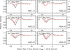 |
Fig. 13 Q-branch NH3 rovibrational spectra of VY CMa. These transitions connect the lower energy levels of the ground-state inversion doublets and the upper levels in the vibrationally excited state. Black lines show the observed spectra from the NASA IRTF and red lines show the modelled spectra. Each modelled spectrum was divided by a smoothed version of itself as in the real data (see Sect. 3.4) in order to induce the similar distortion in the line wings. The transition sQ(2, 2) is contaminated by a telluric CO2 absorption line and therefore a large part of its absorption profile is discarded. |
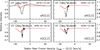 |
Fig. 14 NH3 rovibrational spectra of VY CMa in the transitions aR(0, 0) (top) and aQ(2, 2) (bottom). The black line in the top-left panel shows the observed spectrum from the NASA IRTF while those in other panels show the old spectra from the McMath Solar Telescope, as reproduced from Fig. 1 of McLaren & Betz (1980, © AAS. Reproduced with permission). Red lines show the modelled spectra in all panels. The modelled spectrum in the top-left panel was divided by a smoothed version of itself as in the real data (see Sect. 3.4) in order to induce the similar distortion in the line wings. |
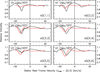 |
Fig. 15 Q-branch NH3 rovibrational spectra of VY CMa. These transitions connect the upper energy levels of the ground-state inversion doublets and the lower levels in the vibrationally excited state. Black lines show the observed spectra from the NASA IRTF and red lines show the modelled spectra. Each modelled spectrum was divided by a smoothed version of itself as in the real data (see Sect. 3.4) in order to induce the similar distortion in the line wings. |
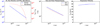 |
Fig. 16 Model for VY CMa. Left: input gas density and NH3 abundance profiles. Only the radii with abundance >10−10 are plotted. Middle: input gas and dust temperature profiles. Right: input expansion velocity profile. |
5.3 OH 231.8+4.2
OH 231.8+4.2 (also known as Rotten Egg Nebula or Calabash Nebula) is a bipolar pre-planetary nebula (PPN) hosting the Mira-type AGB star QX Pup. This object is believed to be evolving into a planetary nebula (Sánchez Contreras et al. 2004). In this study, we assume a distance of 1.54 kpc (Choi et al. 2012) and a systemic LSR velocity of 34 km s−1 (Alcolea et al. 2001). The average estimates of its luminosity and effective temperature are, respectively, ~ 104 L⊙ and ~ 2300 K (Cohen 1981; Kastner et al. 1992; Sánchez Contreras et al. 2002). Using the Stefan-Boltzmann law, L⋆ ∝ R⋆2T⋆4, the stellar radius is estimated to be ~4.4 × 1013 cm = 2.9 AU. High-resolution images of molecular emission of the nebula reveal a very clumpy bipolar outflow with a clear axis of symmetry at the position angle (PA) of about 21° and a plane-of-sky-projected, global velocity gradient (∇V ) of about 6.5 km s−1 arcsec−1 from the north-east to the south-west (e.g. Sánchez Contreras et al. 2000; Alcolea et al. 2001). The fact that the CO emission is very compact (≲ 4″) within each velocity channel of width 6.5 km s−1 suggests that the molecular outflow is highly collimated (Alcolea et al. 2001). Most of the mass (~ 70%) as derived from molecular emission concentrates at the central velocity component, which is known as “I3”, between the LSR velocities of + 10 and + 55 km s−1. This component spatially corresponds to the central molecular clump within a radius of ≲ 4″ from the continuum centre (Alcolea et al. 1996, 2001). The circumstellar material is thought to have been suddenly accelerated about 770 years ago, resulting in a Hubble-like outflow with a constant velocity gradient, ∇V (Alcolea et al. 2001).
At the core of clump I3, the velocity gradient of SO is opposite in direction (i.e. velocity increasing from the south to the north) to the global ∇V as traced by CO, HCO+, and H13 CN within a radius of about 2″ and up to a velocity of about 10 km s−1 relative to our adopted systemic velocity (Sánchez Contreras et al. 2000). In the position-velocity (PV) diagram of SO along the axis of symmetry (Fig. 6 in Sánchez Contreras et al. 2000), there are two regions of enhanced SO emission: one peaks at about 1″ to the north-east and ~5 km s−1 redshifted to the systemic and the other peaks around the zero offset and ~ 5 km s−1 blueshifted to the systemic. Sánchez Contreras et al. (2000) suggested that the peculiar velocity gradient of the core SO emission could indicate the presence of a disc-like structure that is possibly expanding.
5.3.1 VLA observation of OH 231.8+4.2
Our 2013 VLA observation of OH 231.8+4.2 detected all the six covered metastable inversion lines. In each 3 kms−1-wide velocity channel, the NH3 emission is not resolved by the 4″ beam. This is consistent with the compact channel-by-channel CO emission as observed by Alcolea et al. (2001) assuming that the NH3 emission also originates from the collimated bipolar outflow or the central clump I3. Figure 17 shows the integrated intensity maps of all the inversion lines over the LSR velocity range 34 ± 54 km s−1. The NH3 (1, 1) transition shows the most extended spatial distribution of typically ~ 6″ (up to ~9″ along the north-eastern part of the outflow) and the widest velocity range of ± 50 km s−1 relative to the systemic velocity. All other transitions show emission well within the above limits. Therefore, the vast majority of the ammonia molecules are situated in clump I3 as identified by Alcolea et al. (1996, 2001).
Although the emission is not spatially resolved by channels, we see a systematic shift of the emission centroid from the north-east to the south-west with increasing LSR velocity. In Fig. 18, we show the PV diagrams of all six NH3 transitions extracted along the symmetry axis at PA = 21°. A straight line of ∇V = 6.5 km s−1 arcsec−1 is also drawn in each diagram to indicate the global velocity gradient as traced by CO (Alcolea et al. 2001). NH3 (1, 1) is the only transition that somehow follows the global ∇V in its extended (≳2″) emission. Within 2″, however, the intensity of the PV diagram is dominated by a component of enhanced emission at around 0″ –1″ north-east and with the redshifted velocities of 0–15 km s−1. Even more intriguing is the fact that other inversion lines, from (2, 2) to (5, 5) (and perhaps also (6, 6)), show an enhancement near zero offset and in blushifted velocities; but none of them show the distinct redshifted feature at the same position-velocity coordinates in the diagram of (1, 1).
The redshifted and blueshifted components of the NH3-emitting region probably have different kinetic temperatures. Assuming that all inversion lines are optically thin, we can compute the rotational temperatures using the line ratios of different line combinations by the following formula, which is Eq. (1) of Menten & Alcolea (1995):
![Mathematical equation: \begin{equation*} T_{JJ'} = \frac{ \displaystyle \frac{E_{\text{low}} (J, K)}{k} - \frac{E_{\text{low}} (J', K')}{k} }{ \displaystyle \ln \left[ \frac{\int T_{\text{mb}} (J, K) \,\text{d}{v}}{\int T_{\text{mb}} (J',K') \,\text{d}{v}} \frac{J(J+1)}{J'(J'+1)} \frac{K'^2(2J'+1)}{K^2(2J+1)} \frac{{\varg}_{\text{op}} (K')}{{\varg}_{\text{op}} (K)} \right] } ,\end{equation*}](/articles/aa/full_html/2018/04/aa31873-17/aa31873-17-eq18.png) (12)
(12)
where Elow(J, K)∕k (in Kelvin) is the lower energy level and ∫ Tmb (J, K) d v is the velocity-integrated main-beam brightness temperature of the inversion line (J, K). The weighting op(K) is equal to 2 for ortho-NH3 (K = 3, 6, …) and equals 1 for para-NH3 (K = 1, 2, 4, 5, …). We compute the rotational temperatures for the redshifted and blueshifted components separately. From the binned spectra presented in the following subsection, we get the main-beam brightness temperature of the two components from the relative velocity ranges of [7.5, 13.5] km s−1 (where (1, 1) peaks) and [−10.5, −4.5] km s−1 (where other lines peak). The rotational temperature T12 for the redshifted component is 20 K and that of the blueshifted component is 37 K. The upper limits of T14 and T24 for the redshifted component (<41 K and <58 K) are also consistently smaller that the derived values for the blueshifted (54 K and 63 K). We do not show the rotational temperatures involving both ortho- and para-NH3 lines, which are of limited meaning because the conversion between the two species is extremely slow and is not primarily determined by the present temperature (Sect. 2, see also Ho et al. 1979).
As already predicted by Menten & Alcolea (1995) based on single-dish inversion spectra of NH3, the (2, 2) and (3, 3) lines probably exclusively trace the warm material that is close to the central star, while the (1, 1) line (among other molecules) traces the cooler part of the circumstellar gas and the high-velocity outflow. From our analysis of the VLA data, we are able to distinguish the spatial and kinematic components that emit at different inversion lines. NH3 (1, 1) emission predominantly comes from the cool material in the bulk of the clump I3, the inner part of the bipolar outflow up to ~ 6″ –9″, and the redshifted component of enhanced emission, which is possibly part of a disc-like structure, as traced by the inner SO emission. On the other hand, most if not all emission of the higher transitions originates from the warm, blueshifted component of the inner SO emission. This component is spatially close to the centre of the radio continuum.
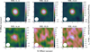 |
Fig. 17 Integrated intensity maps of the six lowest NH3 inversion lines from OH 231.8+4.2 as observed with the VLA over the LSR velocity range of [−20, 88] km s−1 (relative velocity between ±54 km s−1). Horizontal and vertical axes represent the offsets (arcsec) relative to the fitted centre of the continuum in the directions of right ascension and declination, respectively. The circular restoring beam of 4.″ 0 is indicated in the bottom-left corner of each map. The contour levels for the NH3 lines are drawn at: 5, 15, 50, 100, 150σ for (1, 1); 5, 15, 30, 50, 70σ for (2, 2); 5, 15, 30, 45σ for (3, 3); and 3, 6, 9σ for (4, 4) to (6, 6), where σ = 14.6 mJy beam−1 km s−1. |
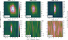 |
Fig. 18 Position-velocity (PV) diagrams of the six lowest NH3 lines as observed with the VLA cutting along the axis of symmetry of OH 231.8+4.2. Vertical axes represent offsets (arcsec) in the north-east direction at the position angle of 21° and horizontal axes represent the LSR velocity ( km s−1). In each PV diagram, the global velocity gradient of ∇V = 6.5 km s−1 arcsec−1 is indicated by the straight line passing through the continuum centre (i.e. zero offset) and the systemic LSR velocity (34 km s −1) of OH 231.8+4.2. |
5.3.2 Herschel/HIFI observations of OH 231.8+4.2
The NH3 JK = 10–00 spectrum ofOH 231.8+4.2 clearly shows two components: a strong, narrow component within ± 20–25 km s−1 relative to the systemic velocity and a weaker, broad component that is only apparent in the redshifted velocity range between ~ 18 km s−1 and ~ 45 km s−1. Both components are asymmetric with signs of self-absorption in blueshifted velocities. Due to poor S/N, higher transitions only show the narrow component but not the broad one. The relative velocity range of the narrow component is consistent with that of the clump I3 (Alcolea et al. 1996), therefore suggesting that most of the rotational line emission originates from this clump within the radius of ~ 4″ .
5.3.3 NH3 model of OH 231.8+4.2
From the above discussion, the NH3 distribution reveals at least two distinguishable parts: (1) a central core containing a possible disc-like structure and (2) an outer outflow following a Hubble-like expansion with a constant velocity gradient. Since the VLA images do not resolve the structure of the possible disc and our code is only 1D, we can only assume spherical symmetry and uniform distribution of the molecule (without any substructures).
We adopt the expansion velocity profile as
 (13)
(13)
The gas density distribution of the nebula is not known. We use again Eq. (6) to describe the density by assuming the conservation of mass. As in the models of Sánchez Contreras et al. (2015) and Velilla Prieto et al. (2015), we adopt a constant mass-loss rate of Ṁ = 1 × 10⁻⁴ M⊙ yr−1 and a characteristic velocity of ⟨Vexp⟩ = 20 km s−1. However, wefound that such density is too low to reproduce the observed intensities of the rotational lines. We have to introduce a density enhancement factor of 3.5 to fit all the spectra. We use the similar abundance profile as in Eq. (10) with R in = 20 R⋆, R e = 2100 R⋆ ≈ 4″, and f0 = 5 × 10⁻⁷. The gas temperature in our model is described by a simple power-law
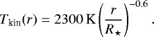 (14)
(14)
Figure 21 shows the radial profiles of our input parameters.
Figures 19 and 20 show the VLA and Herschel/HIFI spectra, respectively. In general, our model is able to predict the observed emission from all available spectra. However, the fitting to the redshifted part of the spectra is unsatisfactory, especially in the (J, K)=(1, 1) and JK = 10–00 lines. As discussed in Sect. 5.3.1, we speculate that some of the redshifted emission comes from a cool component that is shifted to the north-east of the outflow and predominantly emits in (1, 1). Our 1D model assumes the density of the outflow at those velocities to be ~ 104–105 cm−3, while the critical density of the 10 –00 transition is about 1 × 107 cm−3; therefore, this component is likely to be significantly denser than the ambient gas.
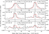 |
Fig. 19 NH3 inversion line spectra of OH 231.8+4.2. Black lines show the VLA spectra in flux density and red lines show the modelled spectra. All transitions were observed in 2013 with D configuration. The spectra were integrated over an 8″ -radius circle. |
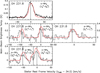 |
Fig. 20 NH3 rotational line spectra of OH 231.8+4.2. Black lines show the observed spectra from Herschel/HIFI and red lines show the modelled spectra. |
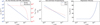 |
Fig. 21 Model for OH 231.8+4.2. Left: input gas density and NH3 abundance profiles. Only the radii with abundance >10−10 are plotted. Middle: input gas and dust temperature profiles. Right: input expansion velocity profile. |
5.4 IRC +10420
5.4.1 VLA observation of IRC +10420
Figure 22 shows the images of NH3 (1, 1) and (2,2) emission from IRC +10420 as observed with the VLA in 2004, before major upgrade of the interferometer. We binned the image cube every 4.9 km s−1 to produce the channel maps. We adopt the systemic velocity to be VLSR = 75 km s−1 (Castro-Carrizo et al. 2007). The two right panels in Fig. 23 show the observed spectra of the flux density over the same 14″ box as displayed in the VLA images (Fig. 22) together with the synthesised spectra as discussed in Sect. 5.4.4.
The NH3 emission appears to be resolved by the restoring beam of FWHM = 3.″7 and appears to be distributed primarily along the east-west directions. The radius of 3σ detection extends up to about 7″ for (1, 1) and 5″ for (2, 2). In general, the spatial distributions of the emission from NH3 (1, 1) and (2, 2) are very similar, with the (1, 1) line being slightly stronger than (2, 2). Most of the NH3 emission is offset to the west/south-west in the VLSR range of ~ 40–70 km s−1, while the emission is shifted to the east in extreme redshifted velocities near 95–105 km s−1. A similar trend of the velocity gradient is also seen in the rotational emission of 13 CO and SO as observed with the SMA by Dinh-V-Trung et al. (2009a).
A close,channel-by-channel comparison of the interferometric images finds that the spatial distribution of the NH3 inversion emission, especially that in the (2, 2) line, is strikingly similar to that of rotational emission in SO JK = 65−54 (Fig. 6 of Dinh-V-Trung et al. 2009a). Both molecules appear to trace the similar clumpy structures in the CSE at various velocities, suggesting that both molecules share the similar kinematics and abundance distribution. The chemical models of Willacy & Millar (1997) for O-rich AGB stars suggest that SO is produced when S, S+ , or HS is produced from ion-neutral reactions or photodissociation and reacts with OH or O. Therefore, most of the SO molecules form in the gas-phase chemistry of the CSE. If the spatial distribution of NH3 is similar to that of SO, then NH3 has to be produced in the CSE rather than the inner wind, as presumed in existing chemical models for lower-mass stars. The apparent lack of centrally peaked emission in our VLA images is consistent with such a scenario.
There is a bright component emitting in both NH3 lines at the radius of ~2″ to the west of the star. This component is the most prominent in the VLSR range of 50–75 km s−1, particularly near 65 km s−1, that is, a blueshifted velocity of 10 km s−1. The high-resolution CO images of IRC +10420 also show a similar bright component between 60 and 75 km s−1, elongated along a PA of 75° (Fig. 6 of Castro-Carrizo et al. 2007). The peaks of the CO-enhanced component are about 4″ and 1″ south-west of the star in the CO J = 1–0 and J = 2–1 transitions, respectively. At VLSR = 65 km s−1, the brightest CO emission arises from an offset of ~2″.
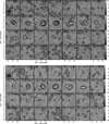 |
Fig. 22 VLA images of NH3 (1, 1) (top) and (2, 2) (bottom) emission from IRC +10420. In each panel, the LSR velocity is shown and the position of IRC +10420 is marked by a cross. The circular restoring beam with a FWHM of 3.″7 is indicated in the bottom-left corner of the first panel. The contour levels for the NH3 lines are drawn at: 3, 4, 5, 6, 7, 8σ, where σ = 0.69 mJy beam−1 for (1, 1) andσ = 0.68 mJy beam−1 for (2, 2). |
5.4.2 Herschel/HIFI observations of IRC +10420
Herschel/HIFI spectra of IRC +10420 are only available for the JK = 10(s)–00(a), 20 (a )–10(s), and 21 (a )–11(s) transitions. The spectra are shown in the top-left and middle-left panels of Fig. 23. The 10 –00 line has the highest S/N and clearly shows asymmetry. The brightness of this line – and perhaps also that of 20 –10 – peaks at VLSR = 65 km s−1, which is the same “peak velocity” as in the VLA data. Therefore, this spectral feature likely corresponds to the bright clump at ~ 2″ west of the star in the VLA images. Additionally, there is a weaker, broad spectral component spanning up to the expansion velocity of ~ 37 km s−1 (e.g. Castro-Carrizo et al. 2007).
By comparing the NH3 10 –00 spectrum with other Herschel/HIFI spectra of IRC +10420 in Teyssier et al. (2012), the NH3 spectral features resemble those of the ortho-H2O and perhaps OH transitions, especially o-H2O  –31,2 and 31,2 –22,1. Teyssier et al. (2012) suggested that both water and ammonia abundances may be enhanced by shock-induced chemistry in the CSE of IRC +10420.
5.4.3 Old McMath observations of IRC +10420
The bottom panel of Fig. 23 shows the MIR aR(0, 0) spectrum reproduced from Fig. 3 of McLaren & Betz (1980). In this spectrum taken in 1979, there are two absorption components at the LSR velocities of ~ 40 km s−1 and ~ 46 km s−1, which correspond to the relative velocities of approximately − 35 km s−1 and − 29 km s−1, respectively, to the systemic velocity. While the more-blueshifted component probably arose from the gas moving towards us at the terminal expansion velocity (as in the cases of IK Tau and VY CMa), the intermediate-velocity component is more intriguing. Owing to the coincidence of their velocities, McLaren & Betz (1980) associated this NH3 absorption component with the 1612 MHz OH maser spots imaged by Benson et al. (1979). Nedoluha & Bowers (1992) interpreted the 1612 MHz OH masers as coming from a shell of radius ~ 8000–9000 AU (~ 1.″5), which was slightly smaller than the MIR continuum of IRC +10420 as imaged by Shenoy et al. (2016). Hence, the NH3 component at VLSR ~ 46 km s−1 could have come from the expanding shell at some offset from the line of sight towards the star, thus causing it to absorb the extended background continuum at a projected line-of-sight velocity.
5.4.4 NH3 model of IRC +10420
IRC +10420 is a yellow hypergiant with an extremely high and variable mass-loss rate (~ 10−4–10−3 M⊙ yr−1, e.g. Shenoy et al. 2016). The CSE of the IRC +10420 is expanding at a maximum speed of about 37 km s−1 (Castro-Carrizo et al. 2007), which is the value we adopt as the constant expansion velocity of the NH3-carrying gas. The gas density and temperature of the CSE have been studied in detail by modelling multiple CO rotational transitions (Teyssier et al. 2012). The CO emission can be well explained by two distinct mass-loss episodes with a period of very low global mass loss in between (Castro-Carrizo et al. 2007; Dinh-V-Trung et al. 2009a).
In our NH3 models, however, we found that the gas density profiles derived from such a mass-loss history are unable to explain the NH3 emission, especially near the radii of 2″ –4″ where there is a low-density “gap” separating the two dominant gas shells. A higher density in the inter-shell region is required in our model. We assume that the density profile of this region corresponds to a uniformly expanding shell with an equivalent mass-loss rate being the average of the inner and outer shells of the model of Castro-Carrizo et al. (2007), that is,
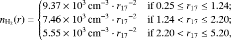 (15)
(15)
where
 (16)
(16)
The gas temperature profile is based on that derived by Teyssier et al. (2012). We assume the gas temperature in the inter-shell region to follow the same power-law as the outer shell, that is,
 (17)
(17)
We found that infrared pumping by dust grains has significant influence on the intensity of the rotational transitions. Assuming a typical dust-to-gas mass ratio of d/g = 0.005 (Oudmaijer et al. 1996), the modelled rotational line intensities are significantly higher than the observed. We had to adopt a lower d/g in order to reduce the contribution of radiative excitation from dust. The following NH3 abundance distribution is found to be able to reproduce the radial intensity profiles of NH3(1, 1) and NH3(2, 2) at the peak velocity (VLSR = 65 km s−1):
 (18)
(18)
Figure 23 shows our model fitting to all available spectra with two different d/g ratios based on the above model. Our modelled aR(0, 0) spectrum does not reproduce the absorption component at the intermediate velocity near − 29 km s−1 because our model does not consider an extended MIR continuum; therefore, line absorption can only occur along the central line of sight and hence at theblueshifted expansion velocity. The radio inversion lines are not affected by the adopted d/g ratio. Our model predicts the inversion lines to be optically thin and show flat-topped spectra. The observed VLA profiles, however, are far from being flat. The synthesised absorption profile at the terminal blueshifted velocity is much deeper than the observed, so is the emission profile in NH3(1, 1). Since our model adopts the oversimplified assumption of a smooth and uniform distribution of NH3 in the CSE, the discrepancies are probably due to the non-uniform distribution of the molecule, particularly in the outer, cooler part of the CSE, which dominates NH3(1, 1) emission and aR(0, 0) absorption.
The input parameters, together with the resultant radial intensity profiles at VLSR = 65 km s−1 and at the systemic velocity (VLSR = 75 km s−1), are plotted in Fig. 24. At VLSR = 65 km s−1, while this model is able to fit the radial intensity profiles within uncertainties, it tends to underestimate the line intensity ratio of NH3(2, 2)/NH3(1, 1). The model cannot produce a satisfactory fit to the radial intensity profiles at the systemic velocity.
The NH3 abundance of ~10−6 is significantly higher, by a factor ranging from 5 to 12.5, than that derived for the inversion lines by Menten et al. (2010). In their model, they used a much higher density which corresponds to a constant mass-loss rate of 2 × 10⁻³ M⊙ yr−1 and is approximately seven times higher than our assumed density. Similar models requiring high gas density to explain molecular line emission have also been reported by Wong (2013) and Quintana-Lacaci et al. (2016) for the SiO molecule. The modelling exercises of Wong (2013) found that it was impossible to explain the SiO emission, in particular the radial intensity profiles, with the model of two disconnected gas shells from Castro-Carrizo et al. (2007). Indeed, a higher gas density throughout the entire SiO-emitting region is required (Wong 2013; Quintana-Lacaci et al. 2016). Therefore, it is speculated that the SiO emission originates from localised clumpy structures, possibly created by shocks, that are notrepresented by the global mass-loss history as traced by CO emission (Wong 2013; Dinh-V-Trung et al. 2017).
Assuming that the dense gas associated with SiO emission is distinct from the diffuse gas producing the bulk of the CO emission, Wong (2013) introduced two models of density and abundance stratification both different from those based on CO. The “three-zone model” retains the shell boundaries in the model of Castro-Carrizo et al. (2007), but adopts an at least four times highergas density throughout the modelled region (Sect. 5.4 of Wong 2013); whereas the “two-zone model” consists of two bordering zones with a higher SiO abundance in the inner one and has the gas density following a single power-law at a shallower gradient than a uniformly expanding envelope (Sect. 6.4 of Wong 2013). The gas density of the two-zone model is generally higher than the CO-based density from Castro-Carrizo et al. (2007) except at the innermost radii (≲ 5 × 1016 cm).
We consider the gas density from the two-zone model as the high-end estimate for IRC +10420’s CSE and derive the minimum NH3 abundance from the optically thin inversion lines. Our adopted gas density profile is slightly modified from that of Wong (2013) and is described as
 (19)
(19)
By fitting the radial intensity profiles at the systemic velocity, we obtain the following NH3 abundance distribution:
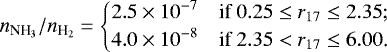 (20)
(20)
Figure 25 shows our model fitting with two different d/g ratios to all available spectra and Fig. 26 shows the plots of the input parameters and the resultant radial intensity profiles. The quality of the fitting and the effects of the d/g ratio are similar to our first model, but the NH3 abundance has been reduced by at least one order of magnitude. Because of the ambiguity of the gas density and abundance, we are unable to conclusively determine the NH3 abundance in the CSE of IRC +10420, which is likely in the range ~ 10−7–10−6. In any case, the density of NH3-emitting gas cannot be the same as that of the ambient medium as traced by CO for a considerable range of radii; we therefore speculate that NH3 emission probably also comes from the dense, localised clumps throughout IRC +10420’s CSE.
Similar to IK Tau, Herschel/PACS observations37 also covered higher rotational transitions from J = 3–2 up to J = 9–8. The only detected features are the J = 3–2 lines. In both of our models, the total flux of the blended lines is within the range of the predicted fluxes spanned by the two adopted d/g ratios.
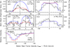 |
Fig. 23 NH3 spectra of IRC +10420. Black lines show the observed spectra; red and blue lines show the modelled spectra from the first model (low density, high abundance) assuming a dust-to-gas mass ratio of 0.001 and 0.005, respectively. The top-left and middle-left spectra are Herschel/HIFI spectra of IRC +10420. The two spectra on the right are VLA spectra showing the flux density integrated over a 14″ × 14″ box centred at IRC +10420, that is, the same region as shown in Fig. 22. The black spectrum in the bottom panel shows the old aR(0, 0) spectrum from the McMath Solar Telescope, as reproduced from Fig. 3 of McLaren & Betz (1980, © AAS. Reproduced with permission). |
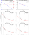 |
Fig. 24 First model for IRC +10420 with low gas density and high NH3 abundance. Top left: input gas density and NH3 abundance profiles. Only the radii with abundance >10−10 are plotted. Top right: input gas and dust temperature profiles. Middle: the radial intensity profiles of NH3 (1, 1) (left) and NH3(2, 2) (right) at the velocity channel VLSR = 65 km s−1, which show the strongest emission in both rotational and inversion transitions. Bottom: the radial intensity profiles of NH3 (1, 1) (left) and NH3(2, 2) (right) at the velocity channel VLSR = 75 km s−1, which is the systemic velocity of IRC +10420. In the radial intensity profiles, black points indicate the binned data points from the VLA images and red curves show the modelled profiles. |
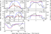 |
Fig. 25 NH3 spectra of IRC +10420. Black lines show the observed spectra; red and blue lines show the modelled spectra from the second model (high density, low abundance) assuming a dust-to-gas mass ratio of 0.001 and 0.005, respectively. The top-left and middle-left spectra are Herschel/HIFI spectra of IRC +10420. The two spectra on the right are VLA spectra showing the flux density integrated over a 14″ × 14″ box centred at IRC +10420, that is, the same region as shown in Fig. 22. The black spectrum in the bottom panel shows the old aR(0, 0) spectrum from the McMath Solar Telescope, as reproduced from Fig. 3 of McLaren & Betz (1980, © AAS. Reproduced with permission). |
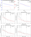 |
Fig. 26 Second model for IRC +10420 with high gas density and low NH3 abundance. Top left: input gas density and NH3 abundance profiles. Only the radii with abundance >10−10 are plotted. Top right: input gas and dust temperature profiles. Middle: radial intensity profiles of NH3 (1, 1) (left) and NH3(2, 2) (right) at the velocity channel VLSR = 65 km s−1, which showthe strongest emission in both rotational and inversion transitions. Bottom: radial intensity profiles of NH3 (1, 1) (left) and NH3(2, 2) (right) at the velocity channel VLSR = 75 km s−1, which is the systemic velocity of IRC +10420. In the radial intensity profiles, black points indicate the binned data points from the VLA images and red curves show the modelled profiles. |
5.5 Ammonia chemistry
Table 3 summarises the adopted parameters and results of our NH3 models. In general, the NH3 abundance required to explain the spectral line data is of the order of 10−7, except for IRC +10420 where this value is a lower limit due to the ambiguous gas density of the CSE. The abundances in IK Tau and VY CMaare a few times lower than those obtained by Menten et al. (2010), in which MIR radiative pumping of the molecule to the v2 = 1 state was not considered. The decrease in the inferred abundance upon the inclusion of infrared pumping has also been reported by Schmidt et al. (2016) for the carbon star IRC +10216, which exhibits a peak abundance of about 3 × 10⁻⁸.
The inner boundaries of the NH3 abundance distribution are <100 R⋆ for IK Tau, VY CMa, and OH 231.8+4.2. The values of Rin are chosen to reproduce the observed line ratios and depend heavily on our assumptions of the gas density and temperature profiles. The MIR profilesof IK Tau, VY CMa, and IRC +10420 appear near the terminal expansion velocities, suggesting that the MIR-absorbing NH3 is in the outer, accelerated part of the CSEs.
None of the four targets in this study show a significant amount of NH3 at radii close to the stellar photosphere, where pulsation-driven shocks dominate the chemistry. Spatially resolved images of IK Tau and IRC +10420 show NH3-emitting clumps thatare offset from the star; unresolved images of VY CMa and OH 231.8+4.2 also show slight departure of the peak emission from the stellar continuum. Furthermore, had NH3 been produced at smaller radii where both density and temperature are very high, emission from higher-J transitions would have been much stronger than the lower ones and the inversion line profiles would have shown narrow features at the outflow or infall velocities during the time of observations. Hence, we conclude that NH3 does not form near the stellar photosphere or in the pulsation-driven shocks in our targets even though tight constraints of Rin could not be determined from available data38.
Parameters of our NH3 models.
Earlier detection of NH3 MIR absorption from O-rich AGB stars includes the Mira variables o Cet and, less likely, R Leo(see Table 2). Betz & Goldhaber (1985) reported large velocity variation in the absorption profiles observed towards o Cet in 1981–1982. At some epochs, NH3 even exhibited redshifted absorption, which is indicative of infall and has never been seen in the NH3 spectra of any other evolved stars. The NH3 absorption up to 20% of the continuum intensity was very strong. In their unpublished spectra, the velocity of the absorption relative to the systemic could reach ~30 km s−1 at its utmost (Betz & Goldhaber 1985). Modern dynamic atmosphere models of Mira variables predict that such strongly varying and high-velocity motions occur in the vicinity of the infrared photosphere (~ 1 R⋆; e.g. Ireland et al. 2008, 2011; Freytag et al. 2017). Chemical modelling suggests that a strong shock of velocity ≳ 30 km s−1 at 1.0 R⋆ could produce a considerable amount of NH3 (Gobrecht et al. 2016). Hence, the MIR lines detected towards o Cet in 1981–1982 likely came from the pulsating wind. However, NH3 detection in o Cet is only sporadic. Our IRTF/TEXES observations in 2016 did not detect NH3 absorption above ~ 5% of the continuum intensity; the Herschel/HIFI observation39 in 2010 also did not find any emission in the rotational transition J = 1–0. In any case, o Cet does not show evidence of high NH3 abundance in the outer CSE and, therefore, it has a very different ammonia chemistry from the targets of this study. The main difference between o Cet and IK Tau is the mass-loss rate (and hence the gas density), which is much lower in o Cet than in IK Tau by a factor of ~30 (Ryde & Schöier 2001; Decin et al. 2010b). High gas density may be one of the criteria of efficient NH3 production.
The photodissociation models of Decin et al. (2010a) and Agúndez et al. (2010) suggest that a significant amount of NH3 could be produced if the CSE were clumpy enough to allow deep penetration of interstellar UV photons. Assuming that one fourth of the solid angle of the incoming UV flux was unattenuated, Agúndez et al. (2010) predicted a high peak NH3 abundance of nearly 10−7 in an O-rich star with the mass-loss rate of IK Tau (~10−5 M⊙ yr−1). This abundance is only a few times lower than our derived value. On the other hand, another consequence of the deep UV photodissociation is the rapid formation of methane (CH4) due to the availability of free carbon atoms. Photochemical models suggest that a substantial amount of CH4 would lead to the formation of excess methanol (CH3OH) and ethynyl radical (C2H) (Charnley et al. 1995); however, the latter two molecules have never been detected towards “typical” O-rich AGB stars40 like IK Tau (e.g. Latter & Charnley 1996a,b; Charnley & Latter 1997; Marvel 2005; Gómez et al. 2014).
Enhanced nitrogen production by stellar nucleosynthesis has been proposed to explain the nitrogen-rich chemistry of some of our targets (Sect. 1). However, nitrogen enhancement alone cannot be the solution of the NH3 abundance problem. Hot bottom burning (HBB) in intermediate-mass AGB stars (M = 4–8 M⊙) can enhance the surface nitrogen abundance at the end of the AGB evolution by up to an order of magnitude (Karakas & Lattanzio 2014; Ventura et al. 2017). In massive stars (M ≳ 8 M⊙), nitrogen is primarily produced in the CN branch of the CNO cycles (Henry et al. 2000) and the surface nitrogen abundance in A-type supergiants could increase by a factor of a few (< 10) compared to the solar value due to partial mixing of the CN-cycled gas (Venn 1995). Optical spectroscopy of the massive hypergiant IRC +10420 also found a similar nitrogen enhancement factor to A-type supergiants (Klochkova et al. 1997). The enhancement of nitrogen by a factor of ≲10 is insufficient to explain the nitrogen chemistry of our targets. For example, nitrogen in IRC +10420 has to be enriched by at least 20 times the solar abundance in order to explain the NO emission (Quintana-Lacaci et al. 2013); the abundance of N-bearing molecules could not be explained even if nitrogen was enhanced by 40 times in the chemical models of Velilla Prieto et al. (2015) and Sánchez Contreras et al. (2015). The line surveys of Tenenbaum et al. (2010a) and Kamiński et al. (2013) did not findnitrogen-rich chemistry in VY CMa, even though the supergiant shows the brightest NH3 rotational emission among our targets. On the other hand, the low-mass AGB star IK Tau is not expected to be enriched in elemental nitrogen abundance by HBB or CNO cycles, yet it shows signs of N-rich chemistry (Sect. 5.1.3 and Velilla Prieto et al. 2017). Furthermore, our observations do not find significant production of NH3 near the stellar photosphere. The effects of nitrogen enrichment on the NH3 abundance are therefore insignificant.
Our modelling shows that NH3 emission probably arises from denser and more turbulent gas than the ambient medium. We find that the turbulence parameters of the NH3-emitting gas in IK Tau and VY CMa have to be significantly higher than the typical values in the bulk of the circumstellar gas so as to fit the broad emission wings in the rotational transitions; our model of OH 231.8+4.2 suggests that a density enhancement of about three to four times is required to fit the spectral lines (Sect. 5.3.3); the strongest NH3 emission of VY CMaand OH 231.8+4.2 comes from localised spatial-kinematic features (in the outer CSE) that could be associated with molecules such as SO and SO2 (Sects. 5.2.1, 5.2.2, and 5.3.1). We note that the abundance of sulphur oxides is yet another mystery in circumstellar chemistry of O-rich stars (e.g. Yamamura et al. 1999; Fu et al. 2012; Adande et al. 2013; Danilovich et al. 2016; Velilla Prieto et al. 2017). Our results may be indicative of some violent processes, such as shocks, in the formation of NH3. A similar interpretation has also been suggested to explain the high abundance and clump distributions of NH3 observed towards the carbon-rich PPNs CRL 2688 (Egg Nebula) and CRL 618 (Martin-Pintado & Bachiller 1992a; Martin-Pintado et al. 1993, 1995; Truong-Bach et al. 1996; Dinh-V-Trung et al. 2009b).
While circumstellar shocks may play a role in producing the excess amount of NH3, the formation mechanism of the molecule in such a scenario is still unknown. In particular, shocks cannot explain the source of free nitrogen atoms. The bond dissociation energy of N2 exceeds 110 000 K and is much higher than that of NH3 (by about 60 000 K; Darwent 1970) because of the N≡N triple bond. Strong shocks are likely to be present near the stellar photosphere, but our observations and chemical models do not find much NH3 in those radii. In addition, the non-detection of emission in the non-metastable (J > K) inversion transitions or rotational transitions within the vibrationally excited state from IK Tau argues against the presence of very dense and hot NH3-emitting gas in the CSE, which would be expected if NH3 formed in shocked gas right after collisional dissociation of the parent species N2 .
IRC +10420 is a peculiar target with a known history of episodic mass loss. The NH3 emission from this star is very far away from the centre of the CSE compared to other targets of this study. Because of the resemblance of NH3’s kinematics and radial intensity distribution to other molecules that are associated with photochemistry (e.g. SO; Willacy & Millar 1997) or shock chemistry (e.g. SiO; Wong 2013; Dinh-V-Trung et al. 2017), the formation of NH3 in IRC +10420 is probably linked to photodissociation or shocks, or both. It is unclear whether the internal UV radiation field from the star is strong enough to dissociate N-bearing parent species in the inner envelope. The CSE of IRC +10420 is highly obscured by dust and no X-rays or UV emission was detected (De Becker et al. 2014). We note that the lack of central NH3 emission has also been observed in CRL 2688. Dinh-V-Trung et al. (2009b) found that NH3 in CRL 2688 mainly traces warm molecular gas in four distinct spatial-kinematic components/lobes, which are associated with shocked gas as traced by CO and near-infrared H2 emission; therefore, the authors suggested that the NH3 abundance in the nebula could be enhanced by shocks.
6 Conclusions and prospects
We present multi-wavelength observations of NH3 emission or absorption in the circumstellar environments of four carefully selected oxygen-rich post-main sequence stars, the AGB star IK Tau , the red supergiant VY CMa, the pre-planetary nebula OH 231.8+4.2, and the yellow hypergiant IRC +10420. These targets were selected because of their diversity in evolutionary stages, previous detection of NH3, and the availability of radiative transfer and chemical models. We detected emission in multiple inversion transitions in the radio K band (~ 1.3 cm) with the VLA and ground-state rotational transitions in the submillimetre wavelengths with Herschel/HIFI from all four targets. We did not detect the rotational transition in the first vibrationally excited state (v2 = 1) near 140 GHz (2.14 mm) from IK Tau. In addition, we detected multiple NH3 rovibrational absorption lines from IK Tauand VY CMa in the MIR N band (~ 10μm) with the TEXES instrument at IRTF.
The VLA images show that NH3 in IK Tau forms quite close to the star at radii within 100 R⋆. In VY CMa , the angular resolution is not enough to clearly resolve the distribution of the gas; however, there are some indications that the strongest NH3 emission is slightly displaced from the stellar continuum by ≲1″ to the south-west and is apparently associated with the SW Clump. The NH3 emission from OH 231.8+4.2 predominantly arises from the central clump, I3. Some fraction of NH3 in OH 231.8+4.2 resides in the bipolar outflow and a distinct kinematic feature (possibly a disc-like structure).
Herschel/HIFI spectra show broad emission lines in all four targets. In IK Tau, VY CMa, and IRC +10420, the line widths are close to or slightly exceed the terminal expansion velocities of the respective targets; therefore, the bulk of the line-emitting gas is located in the fully accelerated CSEs. IRTF spectra show blueshifted absorption close to (IK Tau) or smaller than (VY CMa ) the expansion velocity. Hence, the MIR-absorbing gas in VY CMa is probably near the end of the wind acceleration zone.
We performed radiative transfer modelling on all available spectra. MIR excitation of the molecule to the first vibrationally excited state (v2 = 1) is included. The NH3 abundance is generally of the order of 10−7, which is a few times lower than previous results without MIR pumping (e.g. Menten et al. 2010). Comparing our results with those of IRC +10216 (Schmidt et al. 2016), the NH3 abundance in O-rich CSEs is more than ten times higher than in C-rich CSEs. Both studies find that the inclusion of radiative pumping of NH3 by the MIR continuum from the star and dust shells is important to correctly estimate the molecular abundance: the revised abundances in both environments are significantly lower than previously thought.
We speculate that the high NH3 abundance in circumstellar environments is possibly associated with shock-induced chemistry and photodissociation. However, detailed theoretical models including both shock- and photo-chemistry are not available. Furthermore, the origins of free nitrogen atoms or ions cannot be identified. Free nitrogen is required to trigger successive hydrogenation which leads to the formation of NH3 (e.g. Willacy & Millar 1997; Decin et al. 2010a).
Future imaging of the NH3 inversion line emission with the VLA at sub-arcsecond resolutions would be useful to constrain the inner radius and the spatial-kinematic distribution of the NH3 emission, especially for the strong emission detected in OH 231.8+4.2 and IRC +10420. In addition, simultaneous coverage of SO2 transitions in the radio K band would allow us to verify the association of NH3 with SO2 as seen in some targets. The envisioned next generation Very Large Array (ngVLA; Isella et al. 2015; ngVLA Science Advisory Council 2017) will be useful in searching for non-metastable (J > K) inversion lines, which exclusively trace the densest part (≳108 cm−3) of the NH3-carrying gas (Sweitzer et al. 1979; Ho & Townes 1983). In the (sub)millimetre wavelengths, it is also important to compare the spatial distribution and kinematics of NH3 with other species associated with shocks and photodissociation (such as CS, SO, SO2) and species in the nitrogen network (such as NO, N2 H+) under high angular resolutions. Shocked-excited H2 emission can be observed in the near-infrared to verify the speculation of circumstellar shocks.
The rovibrational absorption profiles provide important constraints on the radii of NH3 molecules by comparing the line absorption velocity and the CSE expansion velocity. There are indications that NH3 forms close to the end of the wind acceleration zone (VY CMa) or exhibits temporal variations in abundance and absorption velocity (o Cet). Additional MIR N-band observationsof other massive stars and Mira variables (such as IRC +10420, VX Sgr, R Leo) at high spectral resolution (R~ 105) are necessary to fully understand the formation of the molecule in evolved stars.
Above v2 = 1, the next lowest vibrationally excited levels are v2 = 2 (s-state only) at 1597.47 cm−1 and v4 = 1 (both states) at 1626.28 and 1627.38 cm−1 (e.g. Yu et al. 2010). These vibrational states are connected to the ground state (0 and 0.79 cm−1) by MIR photons of wavelengths between 6.1 and 6.3 μm. In this study, we assumed that these energy levels are not significantly populated by the MIR radiation of the star and dust. Verification of the assumption by modelling is extremely computationally expensive because the number of transitions increases exponentially. Observations with MIR instruments near 6 μm, such as TEXES at ground-based telescopes or EXES41 aboard the airborne telescope of SOFIA42, would be useful to examine the extent of vibrational excitation of NH3.
Acknowledgements
We thank the anonymous referee for the useful comments. We thank M. R. Schmidt for kindly providing the molecular data files of ortho- and para-NH3. We are grateful to A. Faure for the collisional rate coefficients of ortho- and para-NH3 with ortho-H2, para-H2, and H (Bouhafs et al. 2017); and for the useful comments of the extrapolation methods of the rate coefficients. We are indebted to D. Gobrecht for the insightful discussions of the chemical models of IK Tau (Gobrecht et al. 2016). We would like to express our gratitude to M. J. Richter for the assistance in the preparation of the IRTF proposal and data analysis. We appreciate the generosity of R. A. McLaren and A. L. Betz for giving us the consent and IOP Publishing Ltd. for granting us the permission to reproduce the NH3 spectra as shown in Figs. 1 and 3 of McLaren & Betz (1980). This research has made use of the VizieR catalogue access tool, CDS, Strasbourg, France. The original description of the VizieR service was published in Ochsenbein et al. (2000). We thank Velilla Prieto et al. (2016) for the millimetre spectra of IK Tau and Tenenbaum et al. (2010b) for the table of emission lines in VY CMadeposited in the VizieR database. This research has made use of NASA’s Astrophysics Data System Bibliographic Services. This research has made use of the SIMBAD database, operated at CDS, Strasbourg, France. We acknowledge with thanks the variable star observations from the AAVSO International Database contributed by observers worldwide and used in this research. The Herschel spacecraft was designed, built, tested, and launched under a contract to ESA managed by the Herschel/Planck Project team by an industrial consortium under the overall responsibility of the prime contractor Thales Alenia Space (Cannes), and including Astrium (Friedrichshafen) responsible for the payload module and for system testing at spacecraft level, Thales Alenia Space (Turin) responsible for the service module, and Astrium (Toulouse) responsible for the telescope, with in excess of a hundred subcontractors. HIFI has been designed and built by a consortium of institutes and university departments from across Europe, Canada andthe United States under the leadership of SRON Netherlands Institute for Space Research, Groningen, The Netherlands and with major contributions from Germany, France and the US. Consortium members are: Canada: CSA, U. Waterloo; France: CESR, LAB, LERMA, IRAM; Germany: KOSMA, MPIfR, MPS; Ireland, NUI Maynooth; Italy: ASI, IFSI-INAF, Osservatorio Astrofisico di Arcetri-INAF; Netherlands: SRON, TUD; Poland: CAMK, CBK; Spain: Observatorio Astronómico Nacional (IGN), Centro de Astrobiología (CSIC-INTA). Sweden: Chalmers University of Technology – MC2, RSS & GARD; Onsala Space Observatory; Swedish National Space Board, Stockholm University – Stockholm Observatory; Switzerland: ETH Zurich, FHNW; USA: Caltech, JPL, NHSC. HIPE is a joint development by the Herschel Science Ground Segment Consortium, consisting of ESA, the NASA Herschel Science Center, and the HIFI, PACS and SPIRE consortia. This research has made use of the NASA/IPAC Infrared Science Archive, which is operated by the Jet Propulsion Laboratory, California Institute of Technology, under contract with the National Aeronautics and Space Administration. The version of the ISO data presented in this article correspond to the Highly Processed Data Product (HPDP) sets called “Uniformly processed LWS L01 spectra” by C. Lloyd, M. Lerate, and T. Grundy; and “A uniform database of SWS 2.4–45.4 micron spectra” by G. C. Sloan et al., available for public use in the ISO Data Archive. This research is partly based on observationsat Kitt Peak National Observatory, National Optical Astronomy Observatory (NOAO), which is operated by the Association of Universities for Research in Astronomy (AURA) under cooperative agreement with the National Science Foundation. This research made use of Astropy, a community-developed core Python package for Astronomy (Astropy Collaboration et al. 2013). PyFITS is a product of the Space Telescope Science Institute, which is operated by AURA for NASA. K. T. Wongwas supported for this research through a stipend from the International Max Planck Research School (IMPRS) for Astronomy and Astrophysics at the Universities of Bonn and Cologne and also by the Bonn-Cologne Graduate School of Physics and Astronomy (BCGS).
Appendix A VLA observations
A.1 Observing log
Table A.1 lists all the VLA K-band observations that are relevant to this study and the covered NH3 ground-state inversion lines.
VLA observing log.
Radio continuum
Table A.2 lists the radio continuum measurements of our targets.
Radio continuum measurements.
Appendix B Herschel/HIFI observations
Table B.1 lists all the Herschel/HIFI observations of NH3 ground-state rotational lines used in this study.
Summary of Herschel/HIFI observations.
Appendix C Light curve and period of IK Tau
The most commonly quoted pulsation period of IK Tau is 470 ± 5 days, which was determined by curve-fitting the near-infrared (NIR) flux variation of the star at 1.04 μm (Wing & Lockwood 1973). Wing & Lockwood (1973) suggested the luminosity phase of IK Tau to be represented by
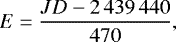 (C.1)
(C.1)
where the integral and fractional parts of E are the number of complete cycles counting from the optical V -band maximum in 1966 Nov. (Cannon 1967) and the visual phase in the cycle, respectively. Hale et al. (1997) also derived the same period of 470 ± 5 days from the (sparsely sampled) MIR fluxes of IK Tau at 11.15 μm. On the other hand, Le Bertre (1993) determined a different period of  days from Fourier analysis of the multi-band NIR (1.24–4.64 μm) light curves of IK Tau.
Since the periods of long-period pulsating variable stars are known to be stochastically variable (Templeton & Karovska 2009), the period of IK Tauderived ≳20 years ago may no longer be valid. To reduce the accumulated errors in the stellar phases, the time of IK Tau’s visual maximum in recent cycles is needed. Based on the photometric data from the American Association of Variable Star Observers (AAVSO) International Database, the relatively well-sampled optical V -band maxima of IK Tau occured in 2007–2009. The difference in periods of 8 days per cycle would lead to a phase difference of about 0.1 in our VLA observations of 2015–2016. In this Appendix, we present a new analysis of the V -band light curve of IK Tau in order to improve the estimates of its pulsation period and phase zero date.
From the AAVSO Database, we only select the V -band observations by the end of 2016 and exclude those without reported uncertainties. These criteria allow observations between 2002 Aug. 10 and 2016 Oct. 07. Figure C.1 shows the V -band light curve of IK Tau and the corresponding time at which NH3 observations were performed. We then carry out time-series analyses using the Lomb-Scargle (LS) periodogram (Lomb 1976; Scargle 1982) in different Python implementations, including the standard LS periodogram in Astropy (version 1.3; Astropy Collaboration et al. 2013), the generalised LS periodogram in astroML (VanderPlas et al. 2012; VanderPlas & Ivezić 2015), and the Bayesian formalism of the generalised LS periodogram (BGLS; Mortier et al. 2015a,b).
The output of BGLS is a probability distribution of period, which allows us to compute the standard deviation straightforwardly. In the Astropy implementation of the standard LS periodogram, we compute the uncertainty from the standard deviation of all the LS peakperiods derived from a set of 10 000 simulated light curves, assuming that the uncertainties of the nominal V -band magnitude obey Gaussian distribution. All the periodograms of the observed V -band light curve show a prominent peak corresponding to the period of 460.05 days. The standard deviations of the period from the BGLS probability and from simulations are 0.02 and 0.06 days, respectively. Therefore, we report the V -band period of IK Tauas 460.05 ± 0.06 days.
We thenphase the V -band light curve with the period of 460.05 days and smooth it with a Savitzky-Golay filter (Savitzky & Golay 1964). We find that the phase zero date of JD 2 454 824 (2008 Dec. 23) can produce an alignment of phase zero with the peak of the smoothed light curve. Figure C.2 shows the phased V -band data and the smoothed light curves. We search the phase zero date around the year 2009.0 because this peak is relatively well-sampled compared to more recent ones.
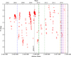 |
Fig. C.1 V -band light curve of IK Tau in 2002–2016. The red points are the observations from the AAVSO International Database. We only include the observations with V magnitude uncertainties. The black vertical line indicates the date of V maximumon JD 2 454 824 (2008 Dec. 23) as determined from the smoothed light curve as displayed in Fig. C.2. Other coloured vertical lines represent the dates of NH3 observations with the VLA D-array (blue: 2004; dark blue: 2015–2016), C-array (purple), B-array (magenta), Herschel/HIFI (green), IRAM 30m (orange), and the IRTF/TEXES instrument (red). |
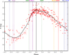 |
Fig. C.2 Phased V -band light curve of IK Tau in 2002–2016. Red points are the observations from the AAVSO International Database and the black curve is the smoothed light curve with a Savitzky-Golay filter. The phases of relevant NH3 observationsare labelled by vertical lines and on the top axis, with the same colour scheme as Fig. C.1. The label “VLA” represents the 2004 VLA observation. The numerals after “D”, “C”, and “B” are the ordinal numbers representingthe dates of VLA observations in 2015–2016 with the corresponding arrays (“B4” is discarded, see Tables A.1 and A.2). |
References
- Adande, G. R., Edwards, J. L., & Ziurys, L. M. 2013, ApJ, 778, 22 [NASA ADS] [CrossRef] [Google Scholar]
- Agúndez, M., Cernicharo, J., & Guélin, M. 2010, ApJ, 724, L133 [NASA ADS] [CrossRef] [Google Scholar]
- Alcolea, J., Bujarrabal, V., & Sánchez Contreras C. 1996, A&A, 312, 560 [NASA ADS] [Google Scholar]
- Alcolea, J., Bujarrabal, V., Sánchez Contreras, C., Neri, R., & Zweigle, J. 2001, A&A, 373, 932 [NASA ADS] [CrossRef] [EDP Sciences] [Google Scholar]
- Alcolea, J., Bujarrabal, V., Planesas, P., et al. 2013, A&A, 559, A93 [NASA ADS] [CrossRef] [EDP Sciences] [Google Scholar]
- Arai, H., Nagai, M., Fujita, S., et al. 2016, PASJ, 68, 76 [NASA ADS] [CrossRef] [Google Scholar]
- Astropy Collaboration, Robitaille, T. P., Tollerud, E. J et al. 2013, A&A, 558, A33 [NASA ADS] [CrossRef] [EDP Sciences] [Google Scholar]
- Balança, C., & Dayou, F. 2017, MNRAS, 469, 1673 [NASA ADS] [CrossRef] [Google Scholar]
- Bell, M. B., Kwok, S., & Feldman, P. A. 1980, in Interstellar Molecules, ed. B. H. Andrew, IAU Symp., 87, 495 [Google Scholar]
- Belov, S. P., Urban, Š., & Winnewisser, G. 1998, J. Mol. Spectr., 189, 1 [NASA ADS] [CrossRef] [Google Scholar]
- Benson, J. M., Mutel, R. L., Fix, J. D., & Claussen, M. J. 1979, ApJ, 229, L87 [NASA ADS] [CrossRef] [Google Scholar]
- Betz, A. 1975, Space Sci. Rev., 17, 677 [NASA ADS] [CrossRef] [Google Scholar]
- Betz, A. L. 1996, in Amazing Light, ed. R. Y. Chiao, 73 [CrossRef] [Google Scholar]
- Betz, A. L., & Goldhaber, D. M. 1985, in Mass Loss from Red Giants, eds. M. Morris, & B. Zuckerman, ASSL, 117, 83 [Google Scholar]
- Betz, A. L., & McLaren, R. A. 1980, in Interstellar Molecules, ed. B. H. Andrew, IAU Symp., 87, 503 [NASA ADS] [Google Scholar]
- Betz, A. L., McLaren, R. A., & Spears, D. L. 1979, ApJ, 229, L97 [NASA ADS] [CrossRef] [Google Scholar]
- Bouhafs, N., Rist, C., Daniel, F., et al. 2017, MNRAS, 470, 2204 [NASA ADS] [CrossRef] [Google Scholar]
- Bujarrabal, V., HIFISTARS & SUCCESS Teams 2011, in Why Galaxies Care about AGB Stars II: Shining Examples and Common Inhabitants, eds. F. Kerschbaum, T. Lebzelter, & R. F. Wing, ASP Conf. Ser., 445, 577 [Google Scholar]
- Bujarrabal, V., Alcolea, J., Soria-Ruiz, R., et al. 2012, A&A, 537, A8 [NASA ADS] [CrossRef] [EDP Sciences] [Google Scholar]
- Bunker, P. R. 1979, Microwave Symmetry and Spectroscopy (New York: Academic Press, Inc.) [Google Scholar]
- Cannon, R. D. 1967, The Observatory, 87, 231 [NASA ADS] [Google Scholar]
- Carter, M., Lazareff, B., Maier, D., et al. 2012, A&A, 538, A89 [NASA ADS] [CrossRef] [EDP Sciences] [Google Scholar]
- Castro-Carrizo, A., Quintana-Lacaci, G., Bujarrabal, V., Neri, R., & Alcolea, J. 2007, A&A, 465, 457 [NASA ADS] [CrossRef] [EDP Sciences] [Google Scholar]
- Castro-Carrizo, A., Quintana-Lacaci, G., Neri, R., et al. 2010, A&A, 523, A59 [NASA ADS] [CrossRef] [EDP Sciences] [Google Scholar]
- Cazzoli, G., Dore, L., & Puzzarini, C. 2009, A&A, 507, 1707 [NASA ADS] [CrossRef] [EDP Sciences] [Google Scholar]
- Charnley, S. B., & Latter, W. B. 1997, MNRAS, 287, 538 [NASA ADS] [CrossRef] [Google Scholar]
- Charnley, S. B., Tielens, A. G. G. M., & Kress, M. E. 1995, MNRAS, 274, L53 [NASA ADS] [CrossRef] [Google Scholar]
- Chen, P., Pearson, J. C., Pickett, H. M., Matsuura, S., & Blake, G. A. 2006, J. Mol. Spectr., 236, 116 [NASA ADS] [CrossRef] [Google Scholar]
- Cheung, A. C., Rank, D. M., Townes, C. H., Thornton, D. D., & Welch, W. J. 1968, Phys. Rev. Lett., 21, 1701 [Google Scholar]
- Cheung, A. C., Rank, D. M., Townes, C. H., Knowles, S. H., & Sullivan, III, W. T. 1969, ApJ, 157, L13 [NASA ADS] [CrossRef] [Google Scholar]
- Cheung, A. C., Chui, M. F., Matsakis, D., Townes, C. H., & Yngvesson, K. S. 1973, ApJ, 186, L73 [NASA ADS] [CrossRef] [Google Scholar]
- Choi, Y. K., Hirota, T., Honma, M., et al. 2008, PASJ, 60, 1007 [NASA ADS] [Google Scholar]
- Choi, Y. K., Brunthaler, A., Menten, K. M., & Reid, M. J. 2012, in Cosmic Masers – from OH to H0, eds. R. S. Booth, W. H. T. Vlemmings, & E. M. L. Humphreys, IAU Symp., 287, 407 [Google Scholar]
- Clegg, P. E., Ade, P. A. R., Armand, C., et al. 1996, A&A, 315, L38 [NASA ADS] [Google Scholar]
- Cohen, M. 1981, PASP, 93, 288 [NASA ADS] [CrossRef] [Google Scholar]
- Cohen, M., Witteborn, F. C., Carbon, D. F., et al. 1992, AJ, 104, 2045 [NASA ADS] [CrossRef] [Google Scholar]
- Cordiner, M. A., Boogert, A. C. A., Charnley, S. B., et al. 2016, ApJ, 828, 51 [NASA ADS] [CrossRef] [Google Scholar]
- Danby, G., Flower, D. R., Valiron, P., Schilke, P., & Walmsley, C. M. 1988, MNRAS, 235, 229 [NASA ADS] [CrossRef] [Google Scholar]
- Danilovich, T., Bergman, P., Justtanont, K., et al. 2014, A&A, 569, A76 [NASA ADS] [CrossRef] [EDP Sciences] [Google Scholar]
- Danilovich, T., De Beck, E., Black, J. H., Olofsson, H., & Justtanont, K. 2016, A&A, 588, A119 [NASA ADS] [CrossRef] [EDP Sciences] [Google Scholar]
- Darwent, B. deB. 1970, National Standard Reference Data Series, 31, DOI: 10.6028/NBS.NSRDS.31 [Google Scholar]
- De Beck, E., Kamiński, T., Patel, N. A., et al. 2013, A&A, 558, A132 [NASA ADS] [CrossRef] [EDP Sciences] [Google Scholar]
- De Beck, E., Vlemmings, W., Muller, S., et al. 2015, A&A, 580, A36 [NASA ADS] [CrossRef] [EDP Sciences] [Google Scholar]
- De Becker, M., Hutsemékers, D., & Gosset, E. 2014, New Astron., 29, 75 [NASA ADS] [CrossRef] [Google Scholar]
- Decin, L., Hony, S., de Koter, A., et al. 2006, A&A, 456, 549 [NASA ADS] [CrossRef] [EDP Sciences] [Google Scholar]
- Decin, L., Agúndez, M., Barlow, M. J., et al. 2010a, Nature, 467, 64 [NASA ADS] [CrossRef] [PubMed] [Google Scholar]
- Decin, L., Justtanont, K., De Beck, E., et al. 2010b, A&A, 521, L4 [Google Scholar]
- Decin, L., Richards, A. M. S., Millar, T. J., et al. 2016, A&A, 592, A76 [NASA ADS] [CrossRef] [EDP Sciences] [Google Scholar]
- de Graauw, T., Haser, L. N., Beintema, D. A., et al. 1996, A&A, 315, L49 [NASA ADS] [Google Scholar]
- de Graauw, T., Helmich, F. P., Phillips, T. G., et al. 2010, A&A, 518, L6 [NASA ADS] [CrossRef] [EDP Sciences] [Google Scholar]
- Deguchi, S., & Goldsmith, P. F. 1985, Nature, 317, 336 [NASA ADS] [CrossRef] [Google Scholar]
- Deguchi, S., Claussen, M. J., & Goldsmith, P. F. 1986, ApJ, 303, 810 [NASA ADS] [CrossRef] [Google Scholar]
- Dinh-V-Trung, Muller, S., Lim, J., Kwok, S., & Muthu, C. 2009a, ApJ, 697, 409 [NASA ADS] [CrossRef] [Google Scholar]
- Dinh-V-Trung, Chiu, P. J., & Lim, J. 2009b, ApJ, 700, 86 [NASA ADS] [CrossRef] [Google Scholar]
- Dinh-V-Trung, Wong, K. T., & Lim, J. 2017, ApJ, 851, 65 [NASA ADS] [CrossRef] [Google Scholar]
- Dolan, J. F. 1965, ApJ, 142, 1621 [NASA ADS] [CrossRef] [Google Scholar]
- Dorschner, J., Begemann, B., Henning, T., Jaeger, C., & Mutschke, H. 1995, A&A, 300, 503 [Google Scholar]
- Duari, D., Cherchneff, I., & Willacy, K. 1999, A&A, 341, L47 [NASA ADS] [Google Scholar]
- Faure, A., & Josselin, E. 2008, A&A, 492, 257 [NASA ADS] [CrossRef] [EDP Sciences] [Google Scholar]
- Faure, A., Hily-Blant, P., Le Gal, R., Rist, C., & Pineau des Forêts, G. 2013, ApJ, 770, L2 [NASA ADS] [CrossRef] [Google Scholar]
- Flower, D. R., & Watt, G. D. 1984, MNRAS, 209, 25 [NASA ADS] [Google Scholar]
- Fonfría, J. P., Hinkle, K. H., Cernicharo, J., et al. 2017, ApJ, 835, 196 [NASA ADS] [CrossRef] [Google Scholar]
- Freytag, B., Liljegren, S., & Höfner, S. 2017, A&A, 600, A137 [NASA ADS] [CrossRef] [EDP Sciences] [Google Scholar]
- Fu, R. R., Moullet, A., Patel, N. A., et al. 2012, ApJ, 746, 42 [NASA ADS] [CrossRef] [Google Scholar]
- Fujita, Y. 1966, Vistas Astron., 7, 71 [NASA ADS] [CrossRef] [Google Scholar]
- Gobrecht, D., Cherchneff, I., Sarangi, A., Plane, J. M. C., & Bromley, S. T. 2016, A&A, 585, A6 [NASA ADS] [CrossRef] [EDP Sciences] [Google Scholar]
- Goldhaber, D. M. 1988, Ph.D. Dissertation, University of California at Berkeley, available via subscription at https://search.proquest.com/docview/303689762 [Google Scholar]
- Gómez, J. F., Uscanga, L., Suárez, O., Rizzo, J. R., & de Gregorio-Monsalvo I. 2014, Rev. Mexicana Astron. Astrofis., 50, 137 [NASA ADS] [Google Scholar]
- Gong, Y., Henkel, C., Spezzano, S., et al. 2015, A&A, 574, A56 [NASA ADS] [CrossRef] [EDP Sciences] [Google Scholar]
- Green, S. 1976, J. Chem. Phys., 64, 3463 [NASA ADS] [CrossRef] [Google Scholar]
- Hale, D. D. S., Bester, M., Danchi, W. C., et al. 1997, ApJ, 490, 407 [NASA ADS] [CrossRef] [Google Scholar]
- Harju, J., Walmsley, C. M., & Wouterloot, J. G. A. 1993, A&AS, 98, 51 [NASA ADS] [Google Scholar]
- Hasegawa, T. I., Kwok, S., Koning, N., et al. 2006, ApJ, 637, 791 [NASA ADS] [CrossRef] [Google Scholar]
- Henry, R. B. C., Edmunds, M. G., & Köppen, J. 2000, ApJ, 541, 660 [NASA ADS] [CrossRef] [Google Scholar]
- Herzberg, G. 1945, Molecular Spectra and Molecular Structure, II: Infrared and Raman Spectra of Polyatomic Molecules, 13th print, 1968 (Princeton: D. Van Nostrand Company, Inc.) [Google Scholar]
- Hinkle, K. H., Lebzelter, T., & Scharlach, W. W. G. 1997, AJ, 114, 2686 [NASA ADS] [CrossRef] [Google Scholar]
- Ho, P. T. P., & Townes, C. H. 1983, ARA&A, 21, 239 [NASA ADS] [CrossRef] [Google Scholar]
- Ho, P. T. P., Barrett, A. H., Myers, P. C., et al. 1979, ApJ, 234, 912 [NASA ADS] [CrossRef] [Google Scholar]
- Höfner, S., Bladh, S., Aringer, B., & Ahuja, R. 2016, A&A, 594, A108 [NASA ADS] [CrossRef] [EDP Sciences] [Google Scholar]
- Hogerheijde, M. R., & van der Tak, F. F. S. 2000, A&A, 362, 697 [NASA ADS] [Google Scholar]
- Holler, C. 1999, Diplomarbeit (Master’s Thesis), Ludwig-Maximilians-Universität München, quoted in Monnier et al. (2000b) [Google Scholar]
- Howard, J. B., & Bright Wilson Jr. E. 1934, J. Chem. Phys., 2, 630 [NASA ADS] [CrossRef] [Google Scholar]
- Humphreys, R. M., Helton, L. A., & Jones, T. J. 2007, AJ, 133, 2716 [NASA ADS] [CrossRef] [Google Scholar]
- Hunter, J. D. 2007, Comput. Sci. Eng., 9, 90 [Google Scholar]
- Ireland, M. J., Scholz, M., & Wood, P. R. 2008, MNRAS, 391, 1994 [NASA ADS] [CrossRef] [Google Scholar]
- Ireland, M. J., Scholz, M., & Wood, P. R. 2011, MNRAS, 418, 114 [NASA ADS] [CrossRef] [Google Scholar]
- Isella, A., Hull, C. L. H., Moullet, A., et al. 2015, Next Generation Very Large Array Memos Series, 6 [arXiv:1510.06444] [Google Scholar]
- Ivezić, Ž., Nenkova, M., & Elitzur, M. 1999, ArXiv e-prints [arXiv:astro-ph/9910475], University of Kentucky Internal Report, accessible at http://www.pa.uky.edu/moshe/dusty/ [Google Scholar]
- Jacquinet-Husson, N., Armante, R., Scott, N. A., et al. 2016, J. Mol. Spectr., 327, 31 [NASA ADS] [CrossRef] [Google Scholar]
- Johnson, H. R., & Sauval, A. J. 1982, A&AS, 49, 77 [NASA ADS] [Google Scholar]
- Jones, T. J., Humphreys, R. M., Gehrz, R. D., et al. 1993, ApJ, 411, 323 [NASA ADS] [CrossRef] [Google Scholar]
- Jones, E., Oliphant, T., Peterson, P., et al. 2001, SciPy: Open source scientific tools for Python, https://www.scipy.org/ [Google Scholar]
- Jura, M., Chen, C., & Plavchan, P. 2002, ApJ, 574, 963 [NASA ADS] [CrossRef] [Google Scholar]
- Justtanont, K., Khouri, T., Maercker, M., et al. 2012, A&A, 537, A144 [NASA ADS] [CrossRef] [EDP Sciences] [Google Scholar]
- Kamiński, T., Gottlieb, C. A., Young, K. H., Menten, K. M., & Patel, N. A. 2013, ApJS, 209, 38 [NASA ADS] [CrossRef] [Google Scholar]
- Kamiński, T., Menten, K. M., Tylenda, R., et al. 2015, Nature, 520, 322 [NASA ADS] [CrossRef] [PubMed] [Google Scholar]
- Kamiński, T., Menten, K. M., Tylenda, R., et al. 2017, A&A, 607, A78 [NASA ADS] [CrossRef] [EDP Sciences] [Google Scholar]
- Karakas, A. I., & Lattanzio, J. C. 2014, PASA, 31, e030 [NASA ADS] [CrossRef] [Google Scholar]
- Kastner, J. H., Weintraub, D. A., Zuckerman, B., et al. 1992, ApJ, 398, 552 [NASA ADS] [CrossRef] [Google Scholar]
- Keady, J. J., & Ridgway, S. T. 1993, ApJ, 406, 199 [NASA ADS] [CrossRef] [Google Scholar]
- Kessler, M. F., Steinz, J. A., Anderegg, M. E., et al. 1996, A&A, 315, L27 [NASA ADS] [Google Scholar]
- Klochkova, V. G., Chentsov, E. L., & Panchuk, V. E. 1997, MNRAS, 292, 19 [NASA ADS] [CrossRef] [Google Scholar]
- Kramer, C., Peñalver, J., & Greve, A. 2013, Improvement of the IRAM 30m telescope beam pattern, v8.2, available at http://www.iram.es/IRAMES/mainWiki/CalibrationPapers [Google Scholar]
- Kukolich, S. G. 1967, Phys. Rev., 156, 83 [NASA ADS] [CrossRef] [Google Scholar]
- Kukolich, S. G., & Wofsy, S. C. 1970, J. Chem. Phys., 52, 5477 [NASA ADS] [CrossRef] [Google Scholar]
- Kwok, S., Bell, M. B., & Feldman, P. A. 1981, ApJ, 247, 125 [NASA ADS] [CrossRef] [Google Scholar]
- Lacy, J. H., Richter, M. J., Greathouse, T. K., Jaffe, D. T., & Zhu, Q. 2002, PASP, 114, 153 [NASA ADS] [CrossRef] [Google Scholar]
- Lagadec, E., Verhoelst, T., Mékarnia, D., et al. 2011, MNRAS, 417, 32 [NASA ADS] [CrossRef] [Google Scholar]
- Latter, W. B., & Charnley, S. B. 1996a, ApJ, 463, L37 [NASA ADS] [CrossRef] [Google Scholar]
- Latter, W. B., & Charnley, S. B. 1996b, ApJ, 465, L81 [NASA ADS] [CrossRef] [Google Scholar]
- Le Bertre T. 1993, A&AS, 97, 729 [NASA ADS] [Google Scholar]
- Lebzelter, T., & Hinkle, K. H. 2002, in Radial and Nonradial Pulsationsn as Probes of Stellar Physics, eds. C. Aerts, T. R. Bedding, & J. Christensen-Dalsgaard, IAU Colloq., 185, ASP Conf. Ser., 259, 556 [NASA ADS] [Google Scholar]
- Li, J., & Guo, H. 2014, Phys. Chem. Chem. Phys., 16, 6753 [CrossRef] [Google Scholar]
- Li, X., Heays, A. N., Visser, R., et al. 2013, A&A, 555, A14 [NASA ADS] [CrossRef] [EDP Sciences] [Google Scholar]
- Li, X., Millar, T. J., Heays, A. N., et al. 2016, A&A, 588, A4 [NASA ADS] [CrossRef] [EDP Sciences] [Google Scholar]
- Liljegren, S., Höfner, S., Eriksson, K., & Nowotny, W. 2017, A&A, 606, A6 [NASA ADS] [CrossRef] [EDP Sciences] [Google Scholar]
- Lloyd, C., Lerate, M. R., & Grundy, T. W. 2013, The LWS LO1 Pipeline, Version 1, available at http://ida.esac.esa.int:8080/hpdp/technical_reports/technote34.html [Google Scholar]
- Lomb, N. R. 1976, Ap&SS, 39, 447 [NASA ADS] [CrossRef] [Google Scholar]
- Longuet-Higgins, H. C. 1963, Mol. Phys., 6, 445 [NASA ADS] [CrossRef] [Google Scholar]
- Lyubimkov, L. S., Lambert, D. L., Korotin, S. A., et al. 2011, MNRAS, 410, 1774 [NASA ADS] [Google Scholar]
- Madhusudhan, N., Agúndez, M., Moses, J. I., & Hu, Y. 2016, Space Sci. Rev., 205, 285 [NASA ADS] [CrossRef] [Google Scholar]
- Maercker, M., Schöier, F. L., Olofsson, H., Bergman, P., & Ramstedt, S. 2008, A&A, 479, 779 [NASA ADS] [CrossRef] [EDP Sciences] [Google Scholar]
- Maercker, M., Danilovich, T., Olofsson, H., et al. 2016, A&A, 591, A44 [Google Scholar]
- Maret, S., Faure, A., Scifoni, E., & Wiesenfeld, L. 2009, MNRAS, 399, 425 [NASA ADS] [CrossRef] [Google Scholar]
- Martin-Pintado, J., & Bachiller, R. 1992a, ApJ, 391, L93 [NASA ADS] [CrossRef] [Google Scholar]
- Martin-Pintado, J., & Bachiller, R. 1992b, ApJ, 401, L47 [NASA ADS] [CrossRef] [Google Scholar]
- Martin-Pintado, J., Gaume, R., Bachiller, R., & Johnson, K. 1993, ApJ, 419, 725 [NASA ADS] [CrossRef] [Google Scholar]
- Martin-Pintado, J., Gaume, R. A., Johnston, K. J., & Bachiller, R. 1995, ApJ, 446, 687 [NASA ADS] [CrossRef] [Google Scholar]
- Marvel, K. B. 2005, AJ, 130, 261 [NASA ADS] [CrossRef] [Google Scholar]
- Matplotlib Developers 2016, matplotlib v1.5.3, DOI: 10.5281/zenodo.61948 [Google Scholar]
- Matsuura, M., Chesneau, O., Zijlstra, A. A., et al. 2006, ApJ, 646, L123 [NASA ADS] [CrossRef] [Google Scholar]
- Mauersberger, R., Henkel, C., & Wilson, T. L. 1988, A&A, 205, 235 [NASA ADS] [Google Scholar]
- McCabe, E. M., Smith, R. C., & Clegg, R. E. S. 1979, Nature, 281, 263 [NASA ADS] [CrossRef] [Google Scholar]
- McCollom, T. M. 2013, Annu. Rev. Earth Planet. Sci., 41, 207 [NASA ADS] [CrossRef] [Google Scholar]
- McLaren, R. A., & Betz, A. L. 1980, ApJ, 240, L159 [NASA ADS] [CrossRef] [Google Scholar]
- McMullin, J. P., Waters, B., Schiebel, D., Young, W., & Golap, K. 2007, in Astronomical Data Analysis Software and Systems XVI, eds. R. A. Shaw, F. Hill, & D. J. Bell, ASP Conf. Ser., 376, 127 [Google Scholar]
- Menten, K. M., & Alcolea, J. 1995, ApJ, 448, 416 [NASA ADS] [CrossRef] [Google Scholar]
- Menten, K. M., Wyrowski, F., Alcolea, J., et al. 2010, A&A, 521, L7 [NASA ADS] [CrossRef] [EDP Sciences] [Google Scholar]
- Mills, E. A. C., & Morris, M. R. 2013, ApJ, 772, 105 [NASA ADS] [CrossRef] [Google Scholar]
- Monnier, J. D., Danchi, W. C., Hale, D. S., et al. 2000a, ApJ, 543, 861 [NASA ADS] [CrossRef] [Google Scholar]
- Monnier, J. D., Danchi, W. C., Hale, D. S., Tuthill, P. G., & Townes, C. H. 2000b, ApJ, 543, 868 [NASA ADS] [CrossRef] [Google Scholar]
- Monnier, J. D., Fitelson, W., Danchi, W. C., & Townes, C. H. 2000c, ApJS, 129, 421 [NASA ADS] [CrossRef] [Google Scholar]
- Morris, M., Guilloteau, S., Lucas, R., & Omont, A. 1987, ApJ, 321, 888 [NASA ADS] [CrossRef] [Google Scholar]
- Mortier, A., Faria, J. P., Correia, C. M., Santerne, A., & Santos, N. C. 2015a, A&A, 573, A101 [NASA ADS] [CrossRef] [EDP Sciences] [Google Scholar]
- Mortier, A., Faria, J. P., Correia, C. M., Santerne, A., & Santos, N. C. 2015b, Astrophysics Source Code Library [record ascl:1504.020] [Google Scholar]
- Mueller, M., Jellema, W., Olberg, M., Moreno, R., & Teyssier, D. 2014, The HIFI Beam: Release 1, Release Note for Astronomers, Tech. Rep. HIFI-ICC-RP-2014-001, v1.1, HIFI-ICC, available at http://herschel.esac.esa.int/twiki/pub/Public/HifiCalibrationWeb/HifiBeamReleaseNote_Sep2014.pdf [Google Scholar]
- Muller, S., Dinh-V-Trung, Lim, J., et al. 2007, ApJ, 656, 1109 [NASA ADS] [CrossRef] [Google Scholar]
- Nakashima, J.-i., Sobolev, A. M., Salii, S. V., et al. 2015, PASJ, 67, 95 [NASA ADS] [CrossRef] [Google Scholar]
- Nakashima, J.-i., Ladeyschikov, D. A., Sobolev, A. M., et al. 2016, ApJ, 825, 16 [NASA ADS] [CrossRef] [Google Scholar]
- Nedoluha, G. E., & Bowers, P. F. 1992, ApJ, 392, 249 [NASA ADS] [CrossRef] [Google Scholar]
- Nercessian, E., Omont, A., Benayoun, J. J., & Guilloteau, S. 1989, A&A, 210, 225 [NASA ADS] [Google Scholar]
- Neugebauer, G., Habing, H. J., van Duinen, R., et al. 1984, ApJ, 278, L1 [Google Scholar]
- Nguyen-Q-Rieu, Graham, D., & Bujarrabal, V. 1984, A&A, 138, L5 [NASA ADS] [Google Scholar]
- ngVLA Science Advisory Council 2017, Next Generation Very Large Array Memos Series, 19, available at https://library.nrao.edu/public/memos/ngvla/NGVLA_19.pdf [Google Scholar]
- Nowotny, W., Höfner, S., & Aringer, B. 2010, A&A, 514, A35 [NASA ADS] [CrossRef] [EDP Sciences] [Google Scholar]
- Ochsenbein, F., Bauer, P., & Marcout, J. 2000, A&AS, 143, 23 [NASA ADS] [CrossRef] [EDP Sciences] [Google Scholar]
- O’Gorman, E., Vlemmings, W., Richards, A. M. S., et al. 2015, A&A, 573, L1 [NASA ADS] [CrossRef] [EDP Sciences] [Google Scholar]
- Oka, T. 1976, in Molecular Spectroscopy: Modern Research, Vol. II, ed. K. N. Rao (New York: Academic Press, Inc.), 229 [Google Scholar]
- Oka, T., Shimizu, F. O., Shimizu, T., & Watson, J. K. G. 1971, ApJ, 165, L15 [NASA ADS] [CrossRef] [Google Scholar]
- Olofsson, H. 2003, in Asymptotic giant branch stars, eds. H. J. Habing, & H. Olofsson (New York: Springer Science+Business Media), 325 [Google Scholar]
- Olofsson, H., Vlemmings, W. H. T., Bergman, P., et al. 2017, A&A, 603, L2 [NASA ADS] [CrossRef] [EDP Sciences] [Google Scholar]
- Ossenkopf, V., Henning, T., & Mathis, J. S. 1992, A&A, 261, 567 [NASA ADS] [Google Scholar]
- Ott, S. 2010, in Astronomical Data Analysis Software and Systems XIX, eds. Y. Mizumoto, K.-I. Morita, & M. Ohishi, ASP Conf. Ser., 434, 139 [Google Scholar]
- Oudmaijer, R. D., & de Wit W. J. 2013, A&A, 551, A69 [NASA ADS] [CrossRef] [EDP Sciences] [Google Scholar]
- Oudmaijer, R. D., Groenewegen, M. A. T., Matthews, H. E., Blommaert, J. A. D. L., & Sahu, K. C. 1996, MNRAS, 280, 1062 [NASA ADS] [CrossRef] [Google Scholar]
- Pérez, F., & Granger, B. E. 2007, Comput. Sci. Eng., 9, 21 [Google Scholar]
- Perley, R. A., & Butler, B. J. 2013, ApJS, 204, 19 [NASA ADS] [CrossRef] [Google Scholar]
- Pety, J. 2005, in SF2A-2005: Semaine de l’ Astrophysique Francaise, eds. F. Casoli, T. Contini, J. M. Hameury, & L. Pagani, 721 [Google Scholar]
- Pickett, H. M., Poynter, R. L., Cohen, E. A., et al. 1998, J. Quant. Spec. Radiat. Transf., 60, 883 [Google Scholar]
- Pilbratt, G. L., Riedinger, J. R., Passvogel, T., et al. 2010, A&A, 518, L1 [CrossRef] [EDP Sciences] [Google Scholar]
- Pillai, T., Wyrowski, F., Carey, S. J., & Menten, K. M. 2006, A&A, 450, 569 [NASA ADS] [CrossRef] [EDP Sciences] [Google Scholar]
- Poglitsch, A., Waelkens, C., Geis, N., et al. 2010, A&A, 518, L2 [NASA ADS] [CrossRef] [EDP Sciences] [Google Scholar]
- Poynter, R. L., & Kakar, R. K. 1975, ApJS, 29, 87 [NASA ADS] [CrossRef] [Google Scholar]
- Poynter, R. L., & Margolis, J. S. 1983, Mol. Phys., 48, 401 [NASA ADS] [CrossRef] [Google Scholar]
- Quintana-Lacaci, G., Agúndez, M., Cernicharo, J., et al. 2013, A&A, 560, L2 [NASA ADS] [CrossRef] [EDP Sciences] [Google Scholar]
- Quintana-Lacaci, G., Agúndez, M., Cernicharo, J., et al. 2016, A&A, 592, A51 [NASA ADS] [CrossRef] [EDP Sciences] [Google Scholar]
- Richter, M. J., Lacy, J. H., Jaffe, D. T., et al. 2006, in Ground-based and Airborne Instrumentation for Astronomy, Proc. SPIE, 6269, 62691H [CrossRef] [Google Scholar]
- Richter, M. J., Ennico, K. A., McKelvey, M. E., & Seifahrt, A. 2010, in Ground-based and Airborne Instrumentation for Astronomy III, Proc. SPIE, 7735, 77356Q [NASA ADS] [CrossRef] [Google Scholar]
- Rizzo, J. R., Palau, A., Jiménez-Esteban, F., & Henkel, C. 2014, A&A, 564, A21 [NASA ADS] [CrossRef] [EDP Sciences] [Google Scholar]
- Roelfsema, P. R., Helmich, F. P., Teyssier, D., et al. 2012, A&A, 537, A17 [NASA ADS] [CrossRef] [EDP Sciences] [Google Scholar]
- Rohatgi, A., & Stanojevic, Z. 2016, WebPlotDigitizer: Version 3.10 of WebPlotDigitizer, DOI: 10.5281/zenodo.51157 [Google Scholar]
- Rothermel, H., Schrey, U., Kaufl, H. U., & Drapatz, S. 1986, in Instrumentation and Research Programmes for Small Telescopes, eds. J. B. Hearnshaw, & P. L. Cottrell, IAU Symp., 118, 431 [NASA ADS] [Google Scholar]
- Roueff, E., & Lique, F. 2013, Chem. Rev., 113, 8906 [CrossRef] [PubMed] [Google Scholar]
- Royer, P., Decin, L., Wesson, R., et al. 2010, A&A, 518, L145 [NASA ADS] [CrossRef] [EDP Sciences] [Google Scholar]
- Ryde, N., & Schöier, F. L. 2001, ApJ, 547, 384 [NASA ADS] [CrossRef] [Google Scholar]
- Salinas, V. N., Hogerheijde, M. R., Bergin, E. A., et al. 2016, A&A, 591, A122 [NASA ADS] [CrossRef] [EDP Sciences] [Google Scholar]
- Contreras, C., Bujarrabal, V., Neri, R., & Alcolea, J. 2000, A&A, 357, 651 [NASA ADS] [Google Scholar]
- Sánchez Contreras, C., Desmurs, J. F., Bujarrabal, V., Alcolea, J., & Colomer, F. 2002, A&A, 385, L1 [NASA ADS] [CrossRef] [EDP Sciences] [Google Scholar]
- Sánchez Contreras, C., Gil de Paz, A., & Sahai, R. 2004, ApJ, 616, 519 [NASA ADS] [CrossRef] [Google Scholar]
- Sánchez Contreras, C., Velilla Prieto, L., Agúndez, M., et al. 2015, A&A, 577, A52 [NASA ADS] [CrossRef] [EDP Sciences] [Google Scholar]
- Sault, R. J., Teuben, P. J., & Wright, M. C. H. 1995, in Astronomical Data Analysis Software and Systems IV, eds. R. A. Shaw, H. E. Payne, & J. J. E. Hayes, ASP Conf. Ser., 77, 433 [Google Scholar]
- Savitzky, A., & Golay, M. J. E. 1964, Anal. Chem., 36, 1627 [NASA ADS] [CrossRef] [Google Scholar]
- Scargle, J. D. 1982, ApJ, 263, 835 [NASA ADS] [CrossRef] [Google Scholar]
- Schilke, P., Walmsley, C. M., Wilson, T. L., & Mauersberger, R. 1990, A&A, 227, 220 [NASA ADS] [Google Scholar]
- Schilke, P., Guesten, R., Schulz, A., Serabyn, E., & Walmsley, C. M. 1992, A&A, 261, L5 [NASA ADS] [Google Scholar]
- Schmidt, M. R., He, J. H., Szczerba, R., et al. 2016, A&A, 592, A131 [NASA ADS] [CrossRef] [EDP Sciences] [Google Scholar]
- Schrey, U. 1986, Dissertation (Ph.D. Dissertation), Technische Universität München, MPE Report 198, translated abstract is available at https://ntrl.ntis.gov/NTRL/dashboard/searchResults/titleDetail/N8715040.xhtml [Google Scholar]
- Schrey, U., Rothermel, H., Käufl, H. U., & Drapatz, S. 1985, in Proc. of the URSI Int. Symp. on Millimeter and Submillimeter Wave Radio Astronomy, Granada, ed. J. Gómez-González, 213 [Google Scholar]
- Shenoy, D., Humphreys, R. M., Jones, T. J., et al. 2016, AJ, 151, 51 [NASA ADS] [CrossRef] [Google Scholar]
- Sloan, G. C., Kraemer, K. E., Price, S. D., & Shipman, R. F. 2003, ApJS, 147, 379 [NASA ADS] [CrossRef] [Google Scholar]
- Smith, N., Humphreys, R. M., Davidson, K., et al. 2001, AJ, 121, 1111 [NASA ADS] [CrossRef] [Google Scholar]
- Sopka, R. J., Hildebrand, R., Jaffe, D. T., et al. 1985, ApJ, 294, 242 [NASA ADS] [CrossRef] [Google Scholar]
- Suh, K.-W. 1999, MNRAS, 304, 389 [NASA ADS] [CrossRef] [Google Scholar]
- Sweitzer, J. S., Palmer, P., Morris, M., Turner, B. E., & Zuckerman, B. 1979, ApJ, 227, 415 [NASA ADS] [CrossRef] [Google Scholar]
- Temi, P., Marcum, P. M., Young, E., et al. 2014, ApJS, 212, 24 [NASA ADS] [CrossRef] [Google Scholar]
- Templeton, M. R., & Karovska, M. 2009, ApJ, 691, 1470 [NASA ADS] [CrossRef] [Google Scholar]
- Tenenbaum, E. D., Dodd, J. L., Milam, S. N., Woolf, N. J., & Ziurys, L. M. 2010a, ApJS, 190, 348 [NASA ADS] [CrossRef] [MathSciNet] [Google Scholar]
- Tenenbaum, E. D., Dodd, J. L., Milam, S. N., Woolf, N. J., & Ziurys, L. M. 2010b, Vizier Online Data Catalog: J/ApJS/190/348 [Google Scholar]
- Teyssier, D., Quintana-Lacaci, G., Marston, A. P., et al. 2012, A&A, 545, A99 [NASA ADS] [CrossRef] [EDP Sciences] [Google Scholar]
- Townes, C. H., & Schawlow, A. L. 1955, Microwave Spectroscopy (New York: Dover Publications, Inc.) [Google Scholar]
- Truong-Bach, Nguyen-Q-Rieu, & Graham, D. 1988, A&A, 199, 291 [NASA ADS] [Google Scholar]
- Truong-Bach, Graham, D., & Nguyen-Q-Rieu. 1996, A&A, 312, 565 [NASA ADS] [Google Scholar]
- Tsuboi, M., Shimanouchi, T., & Mizushima, S. 1958, Spectrochim. Acta, 13, 80 [NASA ADS] [CrossRef] [Google Scholar]
- Tsuji, T. 1964, Ann. Tokyo Astron. Obs., 9, 1 [Google Scholar]
- Tsuji, T. 1973, A&A, 23, 411 [NASA ADS] [Google Scholar]
- Urquhart, J. S., Morgan, L. K., Figura, C. C., et al. 2011, MNRAS, 418, 1689 [NASA ADS] [CrossRef] [Google Scholar]
- van den Ancker, M. E., Asmus, D., Hummel, C., et al. 2016, in Observatory Operations: Strategies, Processes, and Systems VI, Proc. SPIE, 9910, 99102T [Google Scholar]
- VanderPlas, J. T., & Ivezić, Ž. 2015, ApJ, 812, 18 [NASA ADS] [CrossRef] [Google Scholar]
- VanderPlas, J., Connolly, A. J., Ivezić, Z., & Gray, A. 2012, in Proc. Conf. on Intelligent Data Understanding (CIDU), 47, DOI: 10.1109/CIDU.2012.6382200 [Google Scholar]
- van der Walt, S., Colbert, S. C., & Varoquaux, G. 2011, Comput. Sci. Eng., 13, 22 [CrossRef] [Google Scholar]
- Velilla Prieto, L., Sánchez Contreras, C., Cernicharo, J., et al. 2015, A&A, 575, A84 [NASA ADS] [CrossRef] [EDP Sciences] [Google Scholar]
- Velilla Prieto, L., Sánchez Contreras, C., Cernicharo, J., et al. 2016, Vizier Online Data Catalog: J/A&A/597/A25 [Google Scholar]
- Velilla Prieto, L., Sánchez Contreras, C., Cernicharo, J., et al. 2017, A&A, 597, A25 [NASA ADS] [CrossRef] [EDP Sciences] [Google Scholar]
- Venn, K. A. 1995, ApJ, 449, 839 [NASA ADS] [CrossRef] [Google Scholar]
- Ventura, P., Stanghellini, L., Dell’Agli, F., & García-Hernández, D. A. 2017, MNRAS, 471, 4648 [NASA ADS] [CrossRef] [Google Scholar]
- Volk, K., & Cohen, M. 1989, AJ, 98, 1918 [NASA ADS] [CrossRef] [Google Scholar]
- Watson, J. K. G. 1971, J. Mol. Spectr., 40, 536 [NASA ADS] [CrossRef] [Google Scholar]
- Wieching, G. 2014, in Effelsberg Newslett., Vol. 5, issue 1, ed. B. Hutawarakorn Kramer, avaialble at https://issuu.com/effelsbergnewsletter/docs/effnews-jan14-final [Google Scholar]
- Wienen, M., Wyrowski, F., Schuller, F., et al. 2012, A&A, 544, A146 [NASA ADS] [CrossRef] [EDP Sciences] [Google Scholar]
- Willacy, K., & Cherchneff, I. 1998, A&A, 330, 676 [NASA ADS] [Google Scholar]
- Willacy, K., & Millar, T. J. 1997, A&A, 324, 237 [NASA ADS] [Google Scholar]
- Wing, R. F., & Lockwood, G. W. 1973, ApJ, 184, 873 [NASA ADS] [CrossRef] [Google Scholar]
- Winnewisser, G., Belov, S. P., Klaus, Th., & Urban, Š. 1996, Z. Nat. A, 51, 200 [NASA ADS] [Google Scholar]
- Wittkowski, M., Hauschildt, P. H., Arroyo-Torres, B., & Marcaide, J. M. 2012, A&A, 540, L12 [NASA ADS] [CrossRef] [EDP Sciences] [Google Scholar]
- Wong, K. T. 2013, MPhil Thesis, University of Hong Kong, available at http://hub.hku.hk/handle/10722/195970 [Google Scholar]
- Wong, K. T., Kamiński, T., Menten, K. M., & Wyrowski, F. 2016, A&A, 590, A127 [NASA ADS] [CrossRef] [EDP Sciences] [Google Scholar]
- Yamamura, I., de Jong, T., Onaka, T., Cami, J., & Waters, L. B. F. M. 1999, A&A, 341, L9 [NASA ADS] [Google Scholar]
- Yang, Y., Shutler, A., & Grischkowsky, D. 2011, Opt. Express, 19, 8830 [NASA ADS] [CrossRef] [Google Scholar]
- Young, E. T., Becklin, E. E., Marcum, P. M., et al. 2012, ApJ, 749, L17 [NASA ADS] [CrossRef] [Google Scholar]
- Yu, S., Pearson, J. C., Drouin, B. J., et al. 2010, J. Chem. Phys., 133, 174317 [NASA ADS] [CrossRef] [PubMed] [Google Scholar]
- Yurchenko, S. N., Barber, R. J., & Tennyson, J. 2011, MNRAS, 413, 1828 [NASA ADS] [CrossRef] [Google Scholar]
- Zhang, B., Reid, M. J., Menten, K. M., & Zheng, X. W. 2012, ApJ, 744, 23 [NASA ADS] [CrossRef] [Google Scholar]
- Ziurys, L. M., Milam, S. N., Apponi, A. J., & Woolf, N. J. 2007, Nature, 447, 1094 [Google Scholar]
All abundances discussed in this article are in fractions of the abundance of molecular hydrogen (H2).
Radiative transitions with ΔK = ±3 are weakly allowed due to centrifugal distortion, in which the molecular rotation induces a small dipole moment in the direction perpendicular to the principal axis of NH3 (Watson 1971; Oka 1976). However, these transitions are important only under very low gas density (~200 cm−3; Oka et al. 1971). In circumstellar environments, ΔK = ±3 transitions are dominated by collisions.
The National Radio Astronomy Observatory is a facility of the National Science Foundation operated under cooperative agreement by Associated Universities, Inc.
Wideband Interferometer Digital Architecture.
Common Astronomy Software Applications.
Heterodyne Instrument for the Far-Infrared (de Graauw et al. 2010).
Continuum and Line Analysis Single-dish Software.
Grenoble Image and Line Data Analysis Software; http://www.iram.fr/IRAMFR/GILDAS/
Institut de Radioastronomie Millimétrique.
Multichannel Imaging and Calibration Software for Receiver Arrays.
Currently as the McMath-Pierce Solar Telescope of National Solar Observatory, operated by the Association of Universities for Research in Astronomy, Inc. (AURA), under cooperative agreement with the National Science Foundation.
Max Planck Institute for Extraterrestrial Physics.
The Infrared Telescope Facility is operated by the University of Hawaii under contract NNH14CK55B with the National Aeronautics and Space Administration.
From the Mauna Kea Atmospheric Monitor, available at http://mkwc.ifa.hawaii.edu/current/seeing/index.cgi
Gestion et Étude des Informations Spectroscopiques Atmosphériques [Management and Study of Atmospheric Spectroscopic Information], http://ara.abct.lmd.polytechnique.fr/
A Software To pRepare Observations.
The transition of the same ΔJ, ΔK, and change in symmetry.
Infrared Astronomical Satellite (Neugebauer et al. 1984).
Infrared Space Observatory (Kessler et al. 1996).
Short Wavelength Spectrometer (de Graauw et al. 1996).
Long Wavelength Spectrometer (Clegg et al. 1996).
The Photodetector Array Camera and Spectrometer (Poglitsch et al. 2010).
Herschel OBSIDs: 1342203679, 1342203680, 1342203681, 1342238942.
The NH3 formation radius was reported as 40 R⋆′ in Monnier et al. (2000b), where R⋆′ = 0.″4 = 69.1 R ⋆ (Monnier et al. 2000a).
Herschel OBSIDs: 1342208886, 1342208887.
(Sub)millimetre rotational transitions within the v2 = 1 state near 140 GHz and 466 GHz from would be detected in emission towards VY CMa with on-source time of ~ 10 h with the IRAM 30m Telescope or the APEX 12 m telescope (Atacama Pathfinder EXperiment) if NH3 reached a high abundance near the stellar photosphere. Given a velocity law, the predicted line profiles of these transitions are sensitive to the inner radius. However, no such observations exist to our knowledge.
Herschel OBSID: 1342200904.
CH3OH has only been detected (recently) towards two evolved stars and one evolved star candidate thus far, including the post-AGB object HD 101584 (Olofsson et al. 2017), the YHG IRC +10420 at marginal S/N ratios (Quintana-Lacaci et al. 2016), and the peculiar object IRAS 19312+1950 (Nakashima et al. 2015), which is located in a complex region that contains dense interstellar gas (see also Nakashima et al. 2016; Cordiner et al. 2016).
Echelon-Cross-Echelle Spectrograph (Richter et al. 2006, 2010).
Stratospheric Observatory For Infrared Astronomy (Young et al. 2012; Temi et al. 2014).
All Tables
List of MIR NH3 ν2 transitions searched with the TEXES instrument at the NASA IRTF under the programme 2016B064 and their previous detection in evolved stars.
All Figures
|
Fig. 1 Energy level diagram of NH3
showing the ground (v = 0;
lower half) and the first excited vibrational (v2 = 1;
upper half) states. The truncated vertical axes on the left and right show the energy from the ground
(E∕k;
K) and the corresponding wavenumber ( |
| In the text | |
|
Fig. 2 NASA IRTF/TEXES spectra (in black) of IK Tau (left) and VY CMa (right) near the wavelengths (wavenumbers) of 10.7 μm (930 cm −1 ; top), 10.5 μm (950 cm −1 ; middle), and10.3 μm (966 cm −1 ; bottom). The wavenumber axes are in the topocentric frame of reference. The target spectra are normalised and zoomed. The normalised calibrator spectra are plotted in magenta and the fractional atmospheric transmissions are shown in grey. Only the target data with atmospheric transmission greater than 0.8 are plotted. The dark blue dotted lines in each spectrum indicate the positions of the labelled NH3 rovibrational transitions in the stellar rest frame and the green solid lines indicatethe telluric lines (in the observatory frame) that blend with the NH3 lines of VY CMa. We assume the systemic velocities of IK Tau and VY CMa to be 34 km s −1 and 22 km s−1, respectively. |
| In the text | |
|
Fig. 3 Integrated intensity maps of the four lowest NH3 inversion lines from IK Tau as observed with the VLA in B and C configurations over the LSR velocity range of [13, 55] km s−1 (relative velocity between ±21 km s−1 to the systemic). Horizontal and vertical axes represent the offsets (arcsec) relative to the fitted centre of the continuum in the directions of right ascension and declination, respectively. The circular restoring beam of 0.″83 is indicated in the bottom-left corner of each map. The contour levels for the NH3 lines are drawn at 3, 4, 5, 6σ, where σ = 5.4 mJy beam−1 km s−1. |
| In the text | |
|
Fig. 4 NH3 inversion line spectra of IK Tau. Black lines show the VLA spectra in flux density and red lines show the modelled spectra. NH3 (1, 1) and(2, 2) were observed in 2004 (top right and middle right) with D configuration and 2016 (top left and middle left) with both B and C configurations. The 2004 spectra were integrated over a 10″ × 10″ box and the 2016 spectra were integrated over a 2″-radius circle. |
| In the text | |
|
Fig. 5 NH3 rotational line spectra of IK Tau. Black lines show the observed spectra from Herschel/HIFI and red lines show the modelled spectra. |
| In the text | |
|
Fig. 6 Q-branch NH3 rovibrational spectra of IK Tau. These transitions connect the lower energy levels of the ground-state inversion doublets and the upper levels in the vibrationally excited state. Black lines show the observed spectra from the NASA IRTF and red lines show the modelled spectra. Each modelled spectrum was divided by a smoothed version of itself as in the real data (see Sect. 3.4) in order to induce the similar distortion in the line wings. |
| In the text | |
|
Fig. 7 NH3 rovibrational spectra of IK Tau in the transitions aR(0, 0) and sP(1, 0). Black lines show the observed spectra from the NASA IRTF and red lines show the modelled spectra. Each modelled spectrum was divided by a smoothed version of itself as in the real data (see Sect. 3.4) in order to induce the similar distortion in the line wings. |
| In the text | |
|
Fig. 8 Q-branch NH3 rovibrational spectra of IK Tau. These transitions connects the upper energy levels of the ground-state inversion doublets and the lower levels in the vibrationally excited state. Black lines show the observed spectra from the NASA IRTF and red lines show the modelled spectra. Each modelled spectrum was divided by a smoothed version of itself as in the real data (see Sect. 3.4) in order to induce the similar distortion in the line wings. |
| In the text | |
|
Fig. 9 Modelfor IK Tau. Left: input gas density and NH3 abundance profiles. Only the radii with abundance >10−10 are plotted. Middle: input gas and dust temperature profiles. Right: input expansion velocity profile. |
| In the text | |
|
Fig. 10 Integrated intensity maps of the six lowest NH3 inversion lines from VY CMa as observed with the VLA over the LSR velocity range of [−17, 85] km s−1 (relative velocity between ±51 km s−1). Horizontal and vertical axes represent the offsets (arcsec) relative to the fitted centre of the continuum in the directions of right ascension and declination, respectively. The circular restoring beam of 4.″ 0 is indicated in the bottom-left corner of each map. The contour levels for the NH3 lines are drawn at: 3, 6, 9, 12, 15σ for (1, 1); 3, 6, 12, 18, 24σ for (2, 2) and(3, 3); 3, 6, 9, 12σ for (4, 4) to (6, 6), where σ = 14.2 mJy beam−1 km s−1. |
| In the text | |
|
Fig. 11 NH3 inversion line spectra of VY CMa. Black lines show the VLA spectra in flux density and red lines show the modelled spectra. All transitions were observed in 2013 with D configuration. The spectra were integrated over an 8″ -radius circle. |
| In the text | |
|
Fig. 12 NH3 rotational line spectra of VY CMa. Black lines show the observed spectra from Herschel/HIFI and red lines show the modelled spectra. |
| In the text | |
|
Fig. 13 Q-branch NH3 rovibrational spectra of VY CMa. These transitions connect the lower energy levels of the ground-state inversion doublets and the upper levels in the vibrationally excited state. Black lines show the observed spectra from the NASA IRTF and red lines show the modelled spectra. Each modelled spectrum was divided by a smoothed version of itself as in the real data (see Sect. 3.4) in order to induce the similar distortion in the line wings. The transition sQ(2, 2) is contaminated by a telluric CO2 absorption line and therefore a large part of its absorption profile is discarded. |
| In the text | |
|
Fig. 14 NH3 rovibrational spectra of VY CMa in the transitions aR(0, 0) (top) and aQ(2, 2) (bottom). The black line in the top-left panel shows the observed spectrum from the NASA IRTF while those in other panels show the old spectra from the McMath Solar Telescope, as reproduced from Fig. 1 of McLaren & Betz (1980, © AAS. Reproduced with permission). Red lines show the modelled spectra in all panels. The modelled spectrum in the top-left panel was divided by a smoothed version of itself as in the real data (see Sect. 3.4) in order to induce the similar distortion in the line wings. |
| In the text | |
|
Fig. 15 Q-branch NH3 rovibrational spectra of VY CMa. These transitions connect the upper energy levels of the ground-state inversion doublets and the lower levels in the vibrationally excited state. Black lines show the observed spectra from the NASA IRTF and red lines show the modelled spectra. Each modelled spectrum was divided by a smoothed version of itself as in the real data (see Sect. 3.4) in order to induce the similar distortion in the line wings. |
| In the text | |
|
Fig. 16 Model for VY CMa. Left: input gas density and NH3 abundance profiles. Only the radii with abundance >10−10 are plotted. Middle: input gas and dust temperature profiles. Right: input expansion velocity profile. |
| In the text | |
|
Fig. 17 Integrated intensity maps of the six lowest NH3 inversion lines from OH 231.8+4.2 as observed with the VLA over the LSR velocity range of [−20, 88] km s−1 (relative velocity between ±54 km s−1). Horizontal and vertical axes represent the offsets (arcsec) relative to the fitted centre of the continuum in the directions of right ascension and declination, respectively. The circular restoring beam of 4.″ 0 is indicated in the bottom-left corner of each map. The contour levels for the NH3 lines are drawn at: 5, 15, 50, 100, 150σ for (1, 1); 5, 15, 30, 50, 70σ for (2, 2); 5, 15, 30, 45σ for (3, 3); and 3, 6, 9σ for (4, 4) to (6, 6), where σ = 14.6 mJy beam−1 km s−1. |
| In the text | |
|
Fig. 18 Position-velocity (PV) diagrams of the six lowest NH3 lines as observed with the VLA cutting along the axis of symmetry of OH 231.8+4.2. Vertical axes represent offsets (arcsec) in the north-east direction at the position angle of 21° and horizontal axes represent the LSR velocity ( km s−1). In each PV diagram, the global velocity gradient of ∇V = 6.5 km s−1 arcsec−1 is indicated by the straight line passing through the continuum centre (i.e. zero offset) and the systemic LSR velocity (34 km s −1) of OH 231.8+4.2. |
| In the text | |
|
Fig. 19 NH3 inversion line spectra of OH 231.8+4.2. Black lines show the VLA spectra in flux density and red lines show the modelled spectra. All transitions were observed in 2013 with D configuration. The spectra were integrated over an 8″ -radius circle. |
| In the text | |
|
Fig. 20 NH3 rotational line spectra of OH 231.8+4.2. Black lines show the observed spectra from Herschel/HIFI and red lines show the modelled spectra. |
| In the text | |
|
Fig. 21 Model for OH 231.8+4.2. Left: input gas density and NH3 abundance profiles. Only the radii with abundance >10−10 are plotted. Middle: input gas and dust temperature profiles. Right: input expansion velocity profile. |
| In the text | |
|
Fig. 22 VLA images of NH3 (1, 1) (top) and (2, 2) (bottom) emission from IRC +10420. In each panel, the LSR velocity is shown and the position of IRC +10420 is marked by a cross. The circular restoring beam with a FWHM of 3.″7 is indicated in the bottom-left corner of the first panel. The contour levels for the NH3 lines are drawn at: 3, 4, 5, 6, 7, 8σ, where σ = 0.69 mJy beam−1 for (1, 1) andσ = 0.68 mJy beam−1 for (2, 2). |
| In the text | |
|
Fig. 23 NH3 spectra of IRC +10420. Black lines show the observed spectra; red and blue lines show the modelled spectra from the first model (low density, high abundance) assuming a dust-to-gas mass ratio of 0.001 and 0.005, respectively. The top-left and middle-left spectra are Herschel/HIFI spectra of IRC +10420. The two spectra on the right are VLA spectra showing the flux density integrated over a 14″ × 14″ box centred at IRC +10420, that is, the same region as shown in Fig. 22. The black spectrum in the bottom panel shows the old aR(0, 0) spectrum from the McMath Solar Telescope, as reproduced from Fig. 3 of McLaren & Betz (1980, © AAS. Reproduced with permission). |
| In the text | |
|
Fig. 24 First model for IRC +10420 with low gas density and high NH3 abundance. Top left: input gas density and NH3 abundance profiles. Only the radii with abundance >10−10 are plotted. Top right: input gas and dust temperature profiles. Middle: the radial intensity profiles of NH3 (1, 1) (left) and NH3(2, 2) (right) at the velocity channel VLSR = 65 km s−1, which show the strongest emission in both rotational and inversion transitions. Bottom: the radial intensity profiles of NH3 (1, 1) (left) and NH3(2, 2) (right) at the velocity channel VLSR = 75 km s−1, which is the systemic velocity of IRC +10420. In the radial intensity profiles, black points indicate the binned data points from the VLA images and red curves show the modelled profiles. |
| In the text | |
|
Fig. 25 NH3 spectra of IRC +10420. Black lines show the observed spectra; red and blue lines show the modelled spectra from the second model (high density, low abundance) assuming a dust-to-gas mass ratio of 0.001 and 0.005, respectively. The top-left and middle-left spectra are Herschel/HIFI spectra of IRC +10420. The two spectra on the right are VLA spectra showing the flux density integrated over a 14″ × 14″ box centred at IRC +10420, that is, the same region as shown in Fig. 22. The black spectrum in the bottom panel shows the old aR(0, 0) spectrum from the McMath Solar Telescope, as reproduced from Fig. 3 of McLaren & Betz (1980, © AAS. Reproduced with permission). |
| In the text | |
|
Fig. 26 Second model for IRC +10420 with high gas density and low NH3 abundance. Top left: input gas density and NH3 abundance profiles. Only the radii with abundance >10−10 are plotted. Top right: input gas and dust temperature profiles. Middle: radial intensity profiles of NH3 (1, 1) (left) and NH3(2, 2) (right) at the velocity channel VLSR = 65 km s−1, which showthe strongest emission in both rotational and inversion transitions. Bottom: radial intensity profiles of NH3 (1, 1) (left) and NH3(2, 2) (right) at the velocity channel VLSR = 75 km s−1, which is the systemic velocity of IRC +10420. In the radial intensity profiles, black points indicate the binned data points from the VLA images and red curves show the modelled profiles. |
| In the text | |
|
Fig. C.1 V -band light curve of IK Tau in 2002–2016. The red points are the observations from the AAVSO International Database. We only include the observations with V magnitude uncertainties. The black vertical line indicates the date of V maximumon JD 2 454 824 (2008 Dec. 23) as determined from the smoothed light curve as displayed in Fig. C.2. Other coloured vertical lines represent the dates of NH3 observations with the VLA D-array (blue: 2004; dark blue: 2015–2016), C-array (purple), B-array (magenta), Herschel/HIFI (green), IRAM 30m (orange), and the IRTF/TEXES instrument (red). |
| In the text | |
|
Fig. C.2 Phased V -band light curve of IK Tau in 2002–2016. Red points are the observations from the AAVSO International Database and the black curve is the smoothed light curve with a Savitzky-Golay filter. The phases of relevant NH3 observationsare labelled by vertical lines and on the top axis, with the same colour scheme as Fig. C.1. The label “VLA” represents the 2004 VLA observation. The numerals after “D”, “C”, and “B” are the ordinal numbers representingthe dates of VLA observations in 2015–2016 with the corresponding arrays (“B4” is discarded, see Tables A.1 and A.2). |
| In the text | |
Current usage metrics show cumulative count of Article Views (full-text article views including HTML views, PDF and ePub downloads, according to the available data) and Abstracts Views on Vision4Press platform.
Data correspond to usage on the plateform after 2015. The current usage metrics is available 48-96 hours after online publication and is updated daily on week days.
Initial download of the metrics may take a while.