| Issue |
A&A
Volume 523, November-December 2010
|
|
|---|---|---|
| Article Number | A62 | |
| Number of page(s) | 9 | |
| Section | Interstellar and circumstellar matter | |
| DOI | https://doi.org/10.1051/0004-6361/201014163 | |
| Published online | 17 November 2010 | |
Radio and IR study of the massive star-forming region IRAS 16353−4636
1
Instituto Argentino de Radioastronomía, CCT – La Plata (CONICET), C.C.5, (1894)
Villa Elisa,
Argentina
e-mail: This email address is being protected from spambots. You need JavaScript enabled to view it.
; This email address is being protected from spambots. You need JavaScript enabled to view it.
; This email address is being protected from spambots. You need JavaScript enabled to view it.
2
Facultad de Cs. Astronómicas y Geofísicas,
UNLP, Paseo del Bosque s/n,
(1900)
La Plata,
Argentina
e-mail: This email address is being protected from spambots. You need JavaScript enabled to view it.
; This email address is being protected from spambots. You need JavaScript enabled to view it.
3
Departament d’Astronomia i Meteorologia and Institut de Ciènces
del Cosmos (ICC), Universitat de Barcelona (IEEC – UB), Martí i Franquès 1, 08028
Barcelona,
Spain
e-mail: This email address is being protected from spambots. You need JavaScript enabled to view it.
4
Laboratoire AIM (UMR 7158 CEA/DSM-CNRS-Université Paris
Diderot), Irfu/Service
d’Astrophysique, Centre de Saclay, Bât. 709, 91191
Gif-sur-Yvette Cedex,
France
e-mail: This email address is being protected from spambots. You need JavaScript enabled to view it.
5
Australia Telescope National Facility, CSIRO,
PO Box 76, Epping, NSW
1710,
Australia
e-mail: This email address is being protected from spambots. You need JavaScript enabled to view it.
6
Instituto de Astronomía y Física del Espacio
(IAFE), C.C. 67, Suc.
28, ( 1428 )
Buenos Aires,
Argentina
email: This email address is being protected from spambots. You need JavaScript enabled to view it.
7
Centro de Radioastronomía y Astrofísica, Universidad Nacional
Autónoma de México, Morelia
58089,
México
e-mail: This email address is being protected from spambots. You need JavaScript enabled to view it.
8
IALP, UNLP-CONICET,
Argentina
e-mail: This email address is being protected from spambots. You need JavaScript enabled to view it.
Received:
29
January
2010
Accepted:
19
July
2010
Abstract
Context. With the latest infrared surveys, the number of massive protostellar candidates has increased significantly. New studies have posed additional questions on important issues about the formation, evolution, and other phenomena related to them. Complementary to infrared data, radio observations are a good tool to study the nature of these objects, and to diagnose the formation stage.
Aims. Here we study the far-infrared source IRAS 16353–4636 with the aim of understanding its nature and origin. In particular, we search for young stellar objects (YSOs), possible outflow structure, and the presence of non-thermal emission.
Methods. Using high-resolution, multi-wavelength radio continuum data obtained with the Australia Telescope Compact Array⋆, we image IRAS 16353–4636 and its environment from 1.4 to 19.6 GHz, and derive the distribution of the spectral index at maximum angular resolution. We also present new JHKs photometry and spectroscopy data obtained at ESO NTT⋆⋆. 13CO and archival H i line data, and infrared databases (MSX, GLIMPSE, MIPSGal) are also inspected.
Results. The radio continuum emission associated with IRAS 16353–4636 was found to be extended (~10 arcsec), with a bow-shaped morphology above 4.8 GHz, and a strong peak persistent at all frequencies. The NIR photometry led us to identify ten near-IR sources and classify them according to their color. We used the H i line data to derive the source distance, and analyzed the kinematical information from the CO and NIR lines detected.
Conclusions. We have identified the source IRAS 16353−4636 as a new protostellar cluster. In this cluster we recognized three distinct sources: a low-mass YSO, a high-mass YSO, and a mildly confined region of intense and non-thermal radio emission. We propose the latter corresponds to the terminal part of an outflow.
Key words: stars: early-type / radio continuum: stars / radiation mechanisms: non-thermal
The Australia Telescope Compact Array is funded by the Commonwealth of Australia for operation as a National Facility by CSIRO.
Based on observations collected at the European Organisation for Astronomical Research in the Southern Hemisphere, Chile (ESO Programme 073.D-0339, PI S. Chaty).
© ESO, 2010
1. Introduction
The availability, in recent years, of infrared survey products like the MSX (Price et al. 2001) and succesive catalogs have provided an extremely rich database to look for massive young stellar objects. Programs such as the Red MSX Survey (RMS; Lumsden et al. 2002; Hoare et al. 2005) have been successful in finding thousands of candidates. The goals of these surveys have been to confirm the evolutionary status of luminous, embedded sources, to perform a statistical analysis of these objects on galactic scales, and to look for efficient mechanisms for massive star formation.
Observations of star forming regions and associated outflows at radio wavelengths can be used to further our understanding of massive star formation, a topic which is still not completely understood. However, such studies require high angular resolution and sensitivity, because massive young stars are often found at kilo-parsec distances and are usually associated with densely populated clusters of intermediate and low mass stars.
Up to now, only a few massive young stellar objects (massive YSOs or MYSOs) are related to collimated jets mapped at the radio range, such as the Serpens sources (Rodríguez et al. 1989), HH 80-81 (Martí et al. 1993), and IRAS 16547−4247 (Garay et al. 2003). Garay et al. found this last object to be a triple quasi-linear radio source, that shows non-thermal indices at the lobes. The source could be associated with a molecular core. The authors have proposed that it is a MYSO ejecting a collimated wind that interacts with the surrounding interstellar medium, producing shocks and consequent radio emission. In recent years, near-IR and (sub)millimeter line studies have proved very valuable in supplying more information on (M)YSOs; see, for example, Varricatt et al. (2010) and references therein.
We have found an intense infrared source, IRAS 16353−4636 (l,b = 337.99°,0.08°) which seems to share some characteristics with IRAS 16547−4247, the object observed by Garay et al. (2003). The source IRAS 16353−4636 has been cataloged as a star-forming region by Avedisova (2002), based on its IRAS colors, and studied for the first time by Combi et al. (2004). Although the available multi-wavelength data from radio to high-energy gamma rays suggested it could be a microquasar candidate, later X-ray observations with XMM-Newton provided a more precise position that was away from the IRAS source and its radio counterpart (Bodaghee et al. 2006). In fact, the X-ray source has been found to be an accreting X-ray pulsar.
The main goal of this study is to establish the nature of IRAS 16353−4636. Section 2 describes the already known sources in the target field, and details the observation and reduction processes we have carried out. In Sect. 3 we present the results. A discussion is given in Sect. 4 and the conclusions are stated in Sect. 5.
2. Observations and data reduction
2.1. The field of IRAS 16353−4636
The infrared source is centered at (α,δ) [J2000 ] = 16h39m3.52s, −46°42'28.28''. The uncertainty ellipse major and minor axes and position angle are 14'' × 4'', 97° (Beichman et al. 1988). Mid-IR and Far-IR fluxes are given in Table 1. Sources from other catalogs are found in the neighborhood and we plotted them in Fig. 1. The MSX6C catalog (Egan et al. 2003) lists the source G337.9947 + 00.0770, which coincides with IRAS 16353−4636 and is detected at the four MSX bands (Table 1).
In the frame of the RMS Survey, Urquhart et al. (2007) have detected 13CO (J = 1−2) emission lines from the MSX source, using the Mopra Telescope (angular resolution: 20'', velocity resolution: 0.2 km s-1, and noise temperature: 0.1 K). Very recently, Mottram et al. (2010) have estimated the MIPSGal 70 μm flux of the RMS source (Table 1).
In addition, there are two Spitzer-GLIMPSE point sources (SSTGLMC G337.9986 + 0.0758 and G337.9907 + 0.0733, Benjamin et al. 2003; Churchwell et al. 2009) in the vicinity of our target, though neither of them is positionally coincident with IRAS 16353−4636.
The X-ray source IGR J16393−4643 (Bodaghee et al. 2006; Chaty et al. 2008; Corbet et al. 2010), which is of X-ray pulsar origin, is also plotted in Fig. 1. The region also hosts a low-frequency radio source, J163903.9−464215.55, detected with the Giant Millimetre Radio Telescope (GMRT; Pandey et al. 2006) at 610 MHz. There is no spatial correlation between IRAS 16353−4636 and the X-ray and GMRT-radio sources.
Relevant infrared sources in the field.
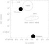 |
Fig. 1 IRAS 16353−4636 (ellipse) and other sources in its field. Spitzer-GLIMPSE point sources: filled circles (Benjamin et al. 2003); MSX6C G337.9947 + 00.0770: square, GMRT-610 MHz J163903.9−464215.55 (Pandey et al. 2006): hollow circle; IGR J16393−4643 (Bodaghee et al. 2006): larger cross. Smaller cross: observations of 13CO line (Urquhart et al. 2007). |
2.2. ATCA
We have carried out radio continuum observations toward the source IRAS 16353−4636, with the Australia Telescope Compact Array (ATCA), at the frequencies 1.384, 2.368, 4.800, 8.640, 17.344, and 19.648 GHz.
Observations in the cm range.
The data were taken in 2004 January 11, in the 6A configuration, at full synthesis (16:00−4:00 UT). The field was observed interleaving simultaneous observations at two frequency pairs: 1.384/2.368 GHz and 4.800/8.640 GHz. PKS 1934−638 served as the flux calibrator, and the nearby source 1646−50 was observed for phase calibration. The total bandwidth at these four frequencies was 128 MHz over 32 channels. The total time on source at each frequency resulted in 247 min at 1.384 and 2.368 GHz, and 201 min at 4.800 and 8.640 GHz.
Observations in the mm range.
We observed simultaneously at 17.344 and 19.648 GHz in 2006 March 29, using ATCA in the 6C configuration (13:00–0.30 UT). The sources PKS 1934−638, 1253−055 and 1646−50 were used as flux, bandpass, and phase calibrators, respectively. The total bandwidth was 128 MHz over 32 channels. The total time on source was 528 min. The high phase stability allowed us to perform 12-min target source scans.
All six data sets were reduced and analyzed with the miriad package. The calibrated visibilities were Fourier-transformed using “natural”, “uniform”, and “robust” weightings. The robust weighted images combine the “natural” lower noise and the “uniform” higher angular resolution (Briggs 1995). The robustness parameter was set to R = 0 for the 6A (cm) data, and to +2 for the 6C (mm) data1. The resulting synthesized beams and rms are given in Table 2.
ATCA observational parameters, and integrated flux density at each frequency.
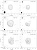 |
Fig. 2 ATCA radio continuum images of IRAS 16353−4636. A: image at 1.4 GHz; contour levels of −3, 3, 5, 10, 18, 30, and 45 times the rms noise of 1.0 mJy beam-1. B: image at 2.4 GHz; contour levels of −3, 3, 5, 10, 18, 30, and 45 times the rms noise of 0.5 mJy beam-1. C: image at 4.8 GHz; contour levels of −3, 3, 6, 9, 12, 20, 30, 45 and 60 times the rms noise of 0.14 mJy beam-1. D: image at 8.64 GHz; contour levels of −3, 3, 6, 9, 12, 20, 24 and 28 times the rms noise of 0.09 mJy beam-1. E: image at 17.344 GHz; contour levels of −3, 3, 5, 8, 11, 14, 17, 19, and 20 times the rms noise of 0.10 mJy beam-1. F: image at 19.648 GHz; contour levels of −3, 3, 5, 8, 11, 14, 17, 19, and 20 times the rms noise of 0.09 mJy beam-1. Synthesized beams are plotted at bottom left corners. North is up and east is to the left |
2.3. VLA data
We searched for data in the VLA archives and found observations centered relatively close
to IRAS 16353−4636, taken in 2001 February 1 at 20 cm in the BnA configuration. The data
were taken with one IF centered at the rest frequency of the hyperfine transition of
H i (1420.406 MHz), with 127 channels over a total bandwidth of 1.56 GHz,
giving a width of 12.2 kHz (or 2.58 km s-1) per channel. After Hanning
smoothing, this resulted in a velocity resolution of 5.16 km s-1 per channel.
The spectral observations were centered at
vLSR = 0 km s-1. The data were edited,
calibrated, and imaged using the software package Astronomical Image Processing System
(AIPS) of NRAO2. The resulting synthesized beam was
 .
.
2.4. NTT NIR
We conducted photometric (J, H and
Ks filters) and spectroscopic (0.9−2.5 μm)
NIR observations of IRAS 16353−4636 on 2004 July
10 with the spectro-imager SofI, installed on the ESO New Technology Telescope (NTT). The
large field imaging of SofI’s detector was used, giving an image scale of
0″̣288 pixel-1 and a field of view of  .
.
We repeated a set of photometric observations for each filter with 9 different 30″ offset positions including IRAS 16353−4636, with an integration time of 90 s for each exposure, following the standard jitter procedure that allows a clean subtraction of the blank sky emission in NIR.
The IRAF (Image Reduction and Analysis Facility package) suite was used to perform the data reduction, which included flat-fielding and NIR sky subtraction. For the three images, one in each filter, we obtained an astrometric solution by using more than 400 coincident 2MASS objects, with a final rms of 0″̣07 in each coordinate.
We carried out aperture photometry and transformed the instrumental magnitudes into apparent magnitudes with the standard relation: magapp = maginst − Zp − ext × AM, where magapp and maginst are respectively the apparent and instrumental magnitudes, Zp is the zero-point, ext the extinction, and AM the airmass. The observations were performed through an airmass close to 1.
The spectroscopic observation consisted of 12 spectra with the Blue and Red grisms of 1000 resolution, and a wavelength coverage of 9000 to 25 000 Å. The position of IRAS 16353−4636 in the slit was offset 30″ in half of the exposures to subtract the blank NIR sky. The total integration time was 240 s in each grism. We took Xe lamp exposures to perform the wavelength calibration. The 5'-long slit was centered at one of the most intense NTT sources that overlaps the radio emission (α,δ[J2000 ] = 16h39m3.18s, −46°42'31.48''). The NTT source was labeled #5 (see Sect. 3.3 and Fig. 5). The position angle of the slit was +15° (positive from north to east), and its width, 1''.
The NIR spectra were reduced with IRAF by flat-fielding, correcting the geometrical distortion using the arc frame, shifting the individual images using the jitter offsets, combining these images, and finally extracting the spectra. The analysis of SofI spectroscopic data, and more precisely the sky subtraction, was difficult due to a variable sky, mainly in the red part of the blue grism, causing some wave patterns. We observed a photometric standard star Hip084636 (G3 V) from the Catalog of Persson et al. (1998), to correct for telluric absorption. The spectra were finally shifted to the lsr rest frame.
3. Results
3.1. ATCA
The continuum images built with the ATCA data are shown in Fig. 2. The angular resolutions range from ~8″, at the lowest radio frequency, to less than 1″ at the highest one. The radio source is detected at all frequencies. The position of the peak flux (PFP) at all frequencies agrees among position uncertainties. At the highest angular resolution (19.6 GHz) we measure (α,δ)PFP [ J2000 ] = 16h39m3.53s, −46°42'29.3''. The integrated flux density Sint is derived summing all the flux above the 3σ contour (1σ = image rms). We adopted an error in the integrated flux density equal to the absolute difference between the integrated flux above 1σ and Sint. Table 2 lists the results. Throughout the text we have followed the convention Sν ∝ να, i.e. a spectral index α > 0 for thermal emission, and α < 0 for non-thermal emission.
At the lowest frequency – 1.4 GHz, and the largest beam – no structure is appreciated. At 2.4 GHz extended emission is detected toward the N-W, though it is better defined at 4.8 GHz. The detections from 4.8 to 19.6 GHz show rather elongated sources, in the direction SW-NE. The images at 17.3 and 19.6 GHz reveal a clumpy structure.
The estimate of the spectral index can help to characterize the radiation regime and, eventually, can lead to a firm identification of the astrophysical source. We build a spectral index map at the highest angular resolution possible, i.e., using the data at 17.3 and 19.6 Ghz. To attain the same angular resolution at the two frequencies we restore the images to the same Gaussian beam size (1'' × 1'') for both data sets.
We consider only pixels with signal-to-noise ≥5. In Fig. 3 we present the resultant spectral index map. It displays fine-scale structure on size scales comparable to the NTT infrared sources, as shown by the Ks contours superimposed on to the spectral index map in Fig. 3.
In general, the index is negative (non-thermal) towards the radio peak seen in Fig. 2, and towards the south of the infrared cluster associated with IRAS 16353−4636, and is positive (thermal) towards the north and west.
Radio observations from massive YSOs have revealed both thermal (as in Martí et al. 1995) and non-thermal outflows or jets (like in Rodríguez et al. 1989). Strong shocks can occur at the end points of the jets, giving rise to diffusive shock particle acceleration which, in turn, will produce non-thermal emission of synchrotron origin (see, for instance, Romero 2010, and references therein).
The rough matching of the 17.3/19.6 GHz spectral index distribution with the NTT image in Fig. 3 shows that (i) the strongest of the southern sources (here called #5, see below) is superimposed on a radio emitting region with α ≪ 0; (ii) at the position of the strongest of the eastern sources (#8, see below), α > 0; and (iii) a negative spectral index corresponds to the pfp radio maximum.
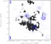 |
Fig. 3 Spectral index map derived for the 17.344 GHz/19.648 GHz ATCA data, in grayscale: black is −1, white is +1. The NTT Ks-band emission is superimposed as contours of 25, 50, 100, 150, 200, 300, and 400 Jy. The lighter (largest) contour corresponds to 3σ level continuum emission at 17.344 GHz. NTT sources here named 5 and 8 are marked (see text). |
3.2. VLA
We produce a continuum image at 1.42 GHz using the line-free channels in the +5 to +152 km s-1 range. It basically matches the ATCA image obtained at 1.384 GHz, thus confirming the results of the ATCA observations albeit with pointing differences. These are probably due to poor phase referencing at low elevations for the VLA.
From the VLA data set, we also obtain H i spectra toward the peak in these radio data. The center of the box region over which the H i emission was averaged coincides with star #5 in our near-IR observations (see below). However, due to the larger angular resolution of the VLA data, the region encompassed all the near-IR sources relevant here. The H i spectrum of the target is presented in Fig. 4, Hanning-smoothed to a resolution of 5.2 km s-1. At negative velocities there is broad absorption down to −100 km s-1, followed by a detached feature spread over 4 channels, centered at a velocity of approximately −120 km s-1.
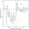 |
Fig. 4 21-cm H i absorption spectrum for the target, plotted as a function of lsr radial velocity. The measured spectrum is divided by the continuum level and represents e−τ, where τ is the optical depth. The horizontal dashed line is drawn at Sline/Scontinuum = 1 and the vertical dashed line is drawn at an lsr radial velocity of 0 km s-1. |
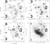 |
Fig. 5 Upper left panel: J-band image of the region toward IRAS 16353−4636, obtained with the NTT on 2004 July 10. Levels: 1, 3, 5, 10, 20, ..., 100, 120, 150, 190, 250, 320, and 400 Jy. The uncertainty in the position of the IRAS source is indicated by an ellipse. Upper right panel: the same as the upper left panel but in the H band. Levels: 5, 10, 20, ..., 400 Jy. We show the position and size of the slit used for spectroscopic purposes. Lower left panel: the same as the upper left panel but in the Ks band. Levels: 20, 30, ..., 400 Jy. The extended emission appears more clearly than in the J- and H-band images. Several point-like sources are visible, and labeled with numbers as in Table 3, at increasing right ascension. Lower right panel: continuum emission at 17.344 GHz in greyscale and grey contours, superimposed on to black contours corresponding to strongest near-IR Ks sources. North is up and east is to the left. |
3.3. NTT NIR
We show the final J, H and Ks band images in Fig. 5; we also compare our 17.3 GHz radio map with the Ks band image in this figure. Besides diffuse NIR emission, there are several point-like objects. We have identified the brightest ones, and numbered them from 1 to 9 at increasing right ascension (labeled in Fig. 5, bottom left panel).
The daophot package in the IRAF suite has been used to extract all the sources in the crowded field through PSF fitting. The aperture has been adapted from 4 to 10 pixels, up to the Airy’s ray if possible, to each source, only to take into account the stellar flux, subtracting the nebula flux. At the end of the extraction process, we apply an aperture correction so as to finally use the same aperture photometry for all of the sources. An adjacent annulus of 1 pixel outer radius is used to estimate the sky background. The results are quoted in Table 3. The magnitudes of the whole extended emission (point-like sources and diffuse emission) are J = 13.1 ± 0.5, H = 11.9 ± 0.2 and Ks = 10.7 ± 0.2.
The NTT photometry is used to build a color − color (C–C) plot. (J−H) versus (H−Ks) colors are plotted in Fig. 6. As a reference, we have included the loci of dwarf, giant and supergiant stars, following the intrinsic colors listed by Tokunaga (2000). Straight dotted lines show the reddening vectors for these stars, and define a band where stars with normal colors, only affected by reddening, are expected to be found in the diagram. All the objects lying to the right of this band show an infrared excess in their H−Ks colors and are presumably young stars still undergoing some form of accretion.
From a global point of view, all the objects in Fig. 6 seem to share a common amount of reddening, equivalent to 8 to 10 mag of extinction in the visual band. The colors of objects #1, 2, 3, and 4 are characteristic of reddened normal stars like foreground objects. The rest of the sources shows an infrared excess at Ks-band; they could represent an embedded cluster of YSOs. We have examined in particular the two brightest Ks sources with colors of protostellar objects (stars #5 and #8). We use NTT spectroscopy, and SED fitting to study #5 and #8, respectively. Notably, source 8 lies close to the IRAS and MSX peak in this region, and is the most extreme outlier in the C–C diagram. Source 8 also coincides with a region of positive spectral index in our radio data (Fig. 3). This is consistent with thermal radio emission which could be associated with a thermal radio jet or optically thick HII region (Martí et al. 1993). Source 8 is therefore potentially the best candidate for an intermediate or even high-mass YSO in the cluster. Source 5, on the other hand, coincides with non-thermal radio emission, as one might expect if this source was also a YSO associated with an outflow (see for example Bosch-Ramon et al. 2010 for theoretical considerations). It is unlikely, however, that source 5 is a UCHII region, since UCHII regions are usually associated with thermal emission (Wood & Churchwell 1989).
Figure 5, bottom right panel, shows the correlation of near-IR emission (Ks band) with radio emission at 17.3 GHz. The radio peak has no near-IR counterpart. The comparison tells us that the spectral index/NTT sources coincidences evident in Fig. 3 must be taken with caution, since the radio emission associated with NIR sources 5 and 8 appears to be swamped by extended emission associated with the radio peak itself. Sources 5 and 8 are not discretely resolved in the radio data. So its not entirely clear that the negative and positive spectral indices observed around sources 5 and 8 are really linked to these NIR point sources. The bulk of the radio emission may be unrelated to the NIR sources.
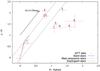 |
Fig. 6 Near-infrared color − color plot (J−H) vs. (H−Ks) derived using the magnitudes measured by us with the NTT, listed in Table 3. The dotted curves show the loci of dwarf, giant and supergiant stars, based on the intrinsic colors by Tokunaga (2000). The straight dotted lines represent the reddening vectors for these stars (see text). |
3.4. Individual sources
Source #5.
Our NTT spectrum of source 5 reveals the presence of H i emission lines and absorption in the CO vibrational bands (12CO and 13CO, Δv = 2 and 3), typical of pre-main sequence stars (see Nisini et al. 2005, and references therein). Figure 7 shows the spectrum with individual lines identified in the J, H, and Ks bands3.
We find the following spectral lines: Paβ, Paδ, 12CO lines and bands, 13CO bands, Brγ, and possibly Br10, Br11. All of them are characteristic of star-forming regions. Many lines peak at velocities close to or more negative than the H i absorption feature at −120 km s-1. Table 4 lists the suggested line identifications, measured wavelengths, rest wavelengths, and measured lsr central velocities. A standard Galactic rotation circular model, such as Brand & Blitz (1993), assigns a minimum velocity of about −125 km s-1 to the gas at the tangent point. Table 4 indicates that the velocity shifts are extremely widespread.
Errors in the determination of radial velocities are strongly dependent on the signal of the individual lines measured and the wavelength resolution of the spectrum. For relatively strong emission lines, such as Brγ, the uncertainty in the estimation of the centroid of the Gaussian profile is expected to be about 1/10 of a pixel, which is equivalent to about 14 km s-1. The uncertainty grows for less intense profiles and largely increases for the CO lines, for which no profile fitting is possible as we are dealing with unresolved absorption bands.
Besides identifying hydrogen emission and CO absorption features that are typical of pre-main-sequence (PMS) interaction, we were also able to identify a few absorption lines, which can be attributed to the PMS star itself. As shown in Fig. 7, Mg I (1.71 μm) and Na I (2.20 μm) seem to be present in our NIR spectrum, although somewhat noisy, with equivalent widths of ~3 Å and ≥2 Å, respectively. Notwithstanding the presence of spectral veiling from the circumstellar disk, we can perform a first-order approximation of the stellar spectral type, making use of the atlas of Rayner et al. (2009) and its discussion in Bik et al. (2010). From the cool star atlas, we find that the present combination of equivalent widths can only be found in a late (K5-M0) dwarf star.
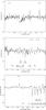 |
Fig. 7 Near-infrared spectrum of the central region of IRAS 16353−4636, acquired with the NTT on 2004 July 10. The identified emission lines are indicated, most notably Paβ, Paδ, 12CO lines and bands, 13CO bands, Brγ, and possibly Br10, and Br11. Upper panel: NIR J-band spectrum. Central panel: NIR H-band spectrum. Lower panel: NIR Ks-band spectrum. |
Source #8.
The position of the MSX source G337.9947+ 0.0770 (Sect. 2) corresponds to NTT source
#8. Mottram and co-workers (2010) have measured the 70-μm flux toward
this MSX source, from the Spitzer-MIPSGal data, also noting that IRAS 60 and
100-μm fluxes can be considered upper limit fluxes of the same
source. We use these mid-infrared fluxes, together with our near-infrared photometry, as
inputs for the SED builder and fitting tool by Robitaille et al. (2007)4. The authors have built
a grid of precomputed radiative transfer models that use a fast
χ2 minimization algorithm. If N is the
number of data points (excluding the upper limits), we select the two models for which
 . In Fig. 8 we plot the best model
that fulfills the last condition. The SED has been built with the NTT
JHKs fluxes, the MSX fluxes, the
70 μm-Spitzer-MIPS flux, and the IRAS 60 and 100 μm
fluxes as upper limits. We have set a distance range from 6 to 10 kpc (see Sect. 4), and
an interstellar visual absorption range from 5 to 12 (Sect. 3.3).
. In Fig. 8 we plot the best model
that fulfills the last condition. The SED has been built with the NTT
JHKs fluxes, the MSX fluxes, the
70 μm-Spitzer-MIPS flux, and the IRAS 60 and 100 μm
fluxes as upper limits. We have set a distance range from 6 to 10 kpc (see Sect. 4), and
an interstellar visual absorption range from 5 to 12 (Sect. 3.3).
4. Discussion
The H i-line self-absorption technique is a useful tool when deriving distances (see, for instance, Busfield et al. 2006). In this way, we measure the most negative absorption feature of the VLA-data spectrum on IRAS 16353−4636 (Fig. 4) at vneg ~ −120 km s-1. The Galactic rotation model of Brand & Blitz (1993) provides two kinematical distances: 6.8 and 9 kpc. The presence of absorption at −120 km s-1 indicates that the source is located at or beyond the sub-central point at a distance of ~8 kpc. At such a distance, 1″ corresponds to 0.04 pc, and the ~10″ size of the radio source, to 0.4 pc. These are typical values for the size of a molecular cloud in the process of contraction to form stars (e.g. Garay et al. 2003). The lack of H i absorption at positive velocities implies that the source is not beyond the solar circle, which sets an upper limit of ≤15 kpc to its distance.
The 13CO line results from Urquhart et al. (2007) confirm that there is molecular gas with v = vneg, at least related to NTT source #8. The Mopra profile shows five emission lines, with lsr-velocities from −122.7 to −38.6 km s-1. Table 5 lists the components, widths, and kinematic distances derived from them (Urquhart et al. 2007). The central velocity of the strongest line is in very good agreement with the extreme H i absorption feature at −120 km s-1. The rest of the detected 13CO lines can be explained, for example, if additional gas clouds are present in the direction of IRAS 16353−4636. Observations with better angular resolution can help to clarify this issue.
Near-IR spectral lines detected in our NTT spectrum of source #5.
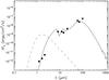 |
Fig. 8 SED fit, using the web tool as explained in Robitaille et al. (2007). The dots represent flux values from NTT source #8 (this work), MSX6C and 70 μm Spitzer-MIPSGal. The triangles represent 60 and 100 μm IRAS data. |
The velocities measured from the near-IR emission and absorption lines in Table 4 are generally consistent with the large negative velocities measured in 13CO. Note in particular that the strongest emission line, Brγ, peaks at an lsr velocity of −137 km s-1 (i.e. within 15 km s-1 the most negative 13CO component).
The bolometric luminosity of IRAS 16353−4636, derived using the IRAS flux values, is
which is a typical value for massive YSOs (Garay et al. 2003).
On the other hand, if we assume that the continuum emission from NTT source #8 has an optically-thin free-free component with flux in the cm wavelengths of the order of 10 mJy (the total flux of the entire radio source at 6 cm is ~80 mJy), and an electron temperature of 104 K for the ionized gas, we find that an ionizing photon flux of Ni ~ 5 × 1047 s-1 (Carpenter et al. 1990) is required to maintain the ionization. This ionizing photon flux can be provided by an O9.5 ZAMS star (Panagia 1973). The luminosity of such a star is 3.8 × 10⁴L⊙, within a factor or two of the bolometric luminosity estimated from the IRAS fluxes. Although the FIR colors could be compatible with an ultracompact H ii region, the source does not appear in the CS survey by Bronfman et al. (1996).
The good fit of the SED model (Fig. 8) of the infrared spectrum of source #8, together with its location in the NIR C–C diagram (Fig. 6), and the agreement with the coordinates of the IRAS and MSX sources in the region, make it the most promising candidate for a MYSO in this cluster. The best fit for an object at ~8 kpc, with AV ~ 10, is achieved for a model source of ~23 solar masses, ~90 solar radius, ~9000 K effective temperature, and 5000 yr of age.
5. Conclusions
From the multi-frequency study presented here on IRAS 16353−4636, we have found strong evidence that supports its nature as a star-forming region. The H i absorption spectrum indicates that the source is located at or beyond the sub-central point at a distance of ~8 kpc. At such a distance, the size of the radio source agrees with typical values for the size of a molecular cloud in the process of contraction to form stars. The region harbors, at least, two pre-main sequence stars or YSOs (NTT sources #5 and #8), plus three YSO candidates (NTT sources #6, #7, and #9). Our photometry shows that these five point sources have infrared excess. NIR spectra obtained from one of these (#5) indicate that it is a low-mass pre-main sequence star, whilst the combination of near- and mid-infrared data suggests that another one (#8) is a massive young stellar object.
The broad H i absorption feature and multiple CO emission lines seen at various velocities along the line of sight towards the region studied here suggest the presence of multiple cloud components.
The radio results reveal that the region is complex, with fine-scale structure seen at the highest frequencies. The results of a spectral index analysis at mm wavelengths are indicative of different physical conditions varying according to position. From 1.4 to 19.6 GHz, the radio emission presents a peak, characterized with a negative spectral index. This can be explained if the peak represents the terminal point of an outflow.
Obtaining NIR spectra for the remaining sources in this region will allow us to improve our knowledge of the whole star forming region, as high-quality spectra provide both physical insight into their sources and kinematical information necessary to disentangle projection effects. Higher angular resolution and better sensitivity observations at low radio frequencies to search for polarized emission, combined with molecular line and continuum studies, are needed to deepen our investigation of this interesting source.
The Australia Telescope Compact Array is funded by the Commonwealth of Australia for operation as a National Facility by CSIRO.
Based on observations collected at the European Organisation for Astronomical Research in the Southern Hemisphere, Chile (ESO Programme 073.D-0339, PI S. Chaty).
“Robust” weights are a function of local u−v weight density: in regions where the weight is low [high], the effective weighting is natural [uniform]. The optimal value thus depends strongly on the configuration. Larger values of R can produce beams that have nearly the same point source sensitivity as the naturally weighted beam, but with enhanced resolution.
The National Radio Astronomy Observatory is a facility of the National Science Foundation operated under cooperative agreement by Associated Universities, Inc.
We checked the lines at http://www.jach.hawaii.edu/UKIRT/astronomy/calib/spec_cal/lines.html
Available on-line at http://caravan.astro.wisc.edu/protostars/
Acknowledgments
We thank the referee, Dr. C.J. Davis, for insightful and constructive comments throughout the paper. We are grateful to the English Department at FCAG-UNLP for the English review. This research has made
use of the NASA’s Astrophysics Data System Abstract Service, and of the SIMBAD database, operated at CDS, Strasbourg, France. The work was supported by grants PICT 2007-00848, Préstamo BID (ANPCyT), FCAG-UNLP project 11/G093, the Centre National d’Etudes Spatiales (CNES), and based on observations obtained through MINE: the Multi-wavelength INTEGRAL Network. M.R., J.A.C., and G.E.R. acknowledge support by DGI of the Spanish Ministerio de Educación y Ciencia (MEC) under grants AYA2007-68034-C03-01/2, FEDER funds and Plan Andaluz de Investigación, Desarrollo e Innovación (PAIDI) of Junta de Andalucía as research group FQM322. M.R. acknowledges financial support from MEC and European Social Funds through a Ramón y Cajal fellowship.
References
- Avedisova, V. S. 2002, Astron. Rep., 46, 3, 193 [NASA ADS] [CrossRef] [Google Scholar]
- Beichman, C. A., Neugebauer, G., Habing, H. J., et al. 1988, IRAS Explanatory Supplement [Google Scholar]
- Benjamin, R. A., Churchwell, E., Babier, B. L., et al. 2003, PASP, 115, 953 [NASA ADS] [CrossRef] [Google Scholar]
- Bik, A., Puga, E., Waters, L. B. F. M., et al. 2010, ApJ, 713, 883 [NASA ADS] [CrossRef] [Google Scholar]
- Bodaghee, A., Walter, R., Zurita Heras, J. A., et al. 2006, A&A, 447, 1027 [NASA ADS] [CrossRef] [EDP Sciences] [Google Scholar]
- Bonnell, I. A., Bate, M. R., & Zinnecker, H. 1998, MNRAS, 298, 93 [NASA ADS] [CrossRef] [Google Scholar]
- Bosch-Ramon, V., Romero, G. E., Araudo, A. T., & Paredes, J. M. 2010, A&A, 511, 8 [Google Scholar]
- Brand, J., & Blitz, L. 1993, A&A, 275, 67 [NASA ADS] [Google Scholar]
- Briggs, D. S. 1995, BAAS, 27, 1444 [NASA ADS] [Google Scholar]
- Bronfman, L., Nyman, L.-A., & May, J. 1996, A&AS, 115, 81 [NASA ADS] [Google Scholar]
- Busfield, A. L., Purcell, C. R., Hoare, M. G., et al. 2006, MNRAS, 366, 1096 [NASA ADS] [CrossRef] [Google Scholar]
- Carpenter, J. M., Snell, R. L., & Schloerb, F. P. 1990, ApJ, 362, 147 [NASA ADS] [CrossRef] [Google Scholar]
- Chaty, S., Rahoui, F., Foellmi, C., et al. 2008, A&A, 484, 783 [NASA ADS] [CrossRef] [EDP Sciences] [Google Scholar]
- Churchwell, E., Babler, B. L., Meade, M. R., et al. 2009, PASP, 121, 213 [NASA ADS] [CrossRef] [Google Scholar]
- Combi, J. A., Ribó, M., Mirabel, I. F., & Sugizaki, M. 2004, A&A, 422, 1031 [NASA ADS] [CrossRef] [EDP Sciences] [Google Scholar]
- Corbet, R. H. D, Krimm, H. A., & Barthelmy, S. D. 2010, ATel, 2570 [Google Scholar]
- Egan, M. O., Price, S. D., & Kraemer, K. E. 2003, AAS, 203, 5708 [NASA ADS] [Google Scholar]
- Garay, G., Brooks, K. J., Mardones, D., & Norris, R. P. 2003, ApJ, 587, 739 [NASA ADS] [CrossRef] [Google Scholar]
- Hoare, M. G., Lumsden, S. L., Oudmaijer, R. D., et al. 2005, IAU Symp., 227, 370 [Google Scholar]
- Lumsden, S. L., Hoare, M. G., Oudmaijer, R. D., & Richards, D. 2002, MNRAS, 336, 621 [NASA ADS] [CrossRef] [Google Scholar]
- Martí, J., Rodríguez, L. F., & Reipurth, B. 1993, ApJ, 416, 208 [NASA ADS] [CrossRef] [Google Scholar]
- Martí, J., Rodríguez, L. F., & Reipurth, B. 1995, ApJ, 449, 184 [NASA ADS] [CrossRef] [Google Scholar]
- McKee, C., & Tan, J. C. 2002, Nature, 416, 59 [NASA ADS] [CrossRef] [PubMed] [Google Scholar]
- Mottram, J. C., Hoare, M. G., Lumsden, S. L., et al. 2010, A&A, 510, 89 [Google Scholar]
- Nisini, B., Antonucci, S., Gianini, T., & Lorenzetti, D. 2005, A&A, 429, 543 [NASA ADS] [CrossRef] [EDP Sciences] [Google Scholar]
- Osorio, M., Lizano, S., & D’Alessio, P. 1999, ApJ, 525, 808 [NASA ADS] [CrossRef] [Google Scholar]
- Panagia, N. 1973, AJ, 78, 929 [NASA ADS] [CrossRef] [Google Scholar]
- Pandey, M., Rao, A. P., Manchada, R., et al. 2006, A&A, 453, 83 [NASA ADS] [CrossRef] [EDP Sciences] [Google Scholar]
- Persson, S. E., Murphy, D. C., Krzeminski, W., Roth, M., & Rieke, M. J. 1998, AJ, 116, 2475 [NASA ADS] [CrossRef] [Google Scholar]
- Price, S. D., Egan, M. P., Carey, S. J., et al. 2001, AJ, 121, 2819 [NASA ADS] [CrossRef] [Google Scholar]
- Rayner, J. T., Cushing, M. C., & Vacca, W. D. 2009, ApJS, 185, 289 [NASA ADS] [CrossRef] [Google Scholar]
- Robitaille, T.P., Whitney, B. A., Indebetouw, R., et al. 2007, ApJS, 167, 256 [Google Scholar]
- Rodríguez, L. F., & Mirabel, I. F. 1998, A&A, 340, L47 [NASA ADS] [Google Scholar]
- Rodríguez, L. F., Curiel, S., Moran, J. M., et al. 1989, ApJ, 346, L85 [NASA ADS] [CrossRef] [Google Scholar]
- Romero, G. E. 2010, Mem.SAI, 81, 181 [Google Scholar]
- Shu, F. H., Adams, F. C., & Lizano, S. 1987, ARA&A, 25, 23 [Google Scholar]
- Shu, F. H., Najita, J., Galli, D., Ostriker, E., & Lizano, S. 1993, Protostars and Planets III, ed. E. H. Levy & J. I. Lunine (Tuscon: Univ. Arizona Press) [Google Scholar]
- Tokunaga, A. T. 2000, in Allen’s Astrophysical Quantities, ed. A. N. Cox, 143 [Google Scholar]
- Urquhart, J. S., Busfield, A. L., Hoare, M. G., et al. 2007, A&A, 474, 891 [NASA ADS] [CrossRef] [EDP Sciences] [Google Scholar]
- Varricatt, W. P., Davis, C. J., Ramsay, S., & Todd, S. P. 2010, MNRAS, 404, 661 [NASA ADS] [CrossRef] [Google Scholar]
- Wood, D. O. S., & Churchwell, E. 1989, ApJS, 69, 831 [NASA ADS] [CrossRef] [Google Scholar]
All Tables
All Figures
|
Fig. 1 IRAS 16353−4636 (ellipse) and other sources in its field. Spitzer-GLIMPSE point sources: filled circles (Benjamin et al. 2003); MSX6C G337.9947 + 00.0770: square, GMRT-610 MHz J163903.9−464215.55 (Pandey et al. 2006): hollow circle; IGR J16393−4643 (Bodaghee et al. 2006): larger cross. Smaller cross: observations of 13CO line (Urquhart et al. 2007). |
| In the text | |
|
Fig. 2 ATCA radio continuum images of IRAS 16353−4636. A: image at 1.4 GHz; contour levels of −3, 3, 5, 10, 18, 30, and 45 times the rms noise of 1.0 mJy beam-1. B: image at 2.4 GHz; contour levels of −3, 3, 5, 10, 18, 30, and 45 times the rms noise of 0.5 mJy beam-1. C: image at 4.8 GHz; contour levels of −3, 3, 6, 9, 12, 20, 30, 45 and 60 times the rms noise of 0.14 mJy beam-1. D: image at 8.64 GHz; contour levels of −3, 3, 6, 9, 12, 20, 24 and 28 times the rms noise of 0.09 mJy beam-1. E: image at 17.344 GHz; contour levels of −3, 3, 5, 8, 11, 14, 17, 19, and 20 times the rms noise of 0.10 mJy beam-1. F: image at 19.648 GHz; contour levels of −3, 3, 5, 8, 11, 14, 17, 19, and 20 times the rms noise of 0.09 mJy beam-1. Synthesized beams are plotted at bottom left corners. North is up and east is to the left |
| In the text | |
|
Fig. 3 Spectral index map derived for the 17.344 GHz/19.648 GHz ATCA data, in grayscale: black is −1, white is +1. The NTT Ks-band emission is superimposed as contours of 25, 50, 100, 150, 200, 300, and 400 Jy. The lighter (largest) contour corresponds to 3σ level continuum emission at 17.344 GHz. NTT sources here named 5 and 8 are marked (see text). |
| In the text | |
|
Fig. 4 21-cm H i absorption spectrum for the target, plotted as a function of lsr radial velocity. The measured spectrum is divided by the continuum level and represents e−τ, where τ is the optical depth. The horizontal dashed line is drawn at Sline/Scontinuum = 1 and the vertical dashed line is drawn at an lsr radial velocity of 0 km s-1. |
| In the text | |
|
Fig. 5 Upper left panel: J-band image of the region toward IRAS 16353−4636, obtained with the NTT on 2004 July 10. Levels: 1, 3, 5, 10, 20, ..., 100, 120, 150, 190, 250, 320, and 400 Jy. The uncertainty in the position of the IRAS source is indicated by an ellipse. Upper right panel: the same as the upper left panel but in the H band. Levels: 5, 10, 20, ..., 400 Jy. We show the position and size of the slit used for spectroscopic purposes. Lower left panel: the same as the upper left panel but in the Ks band. Levels: 20, 30, ..., 400 Jy. The extended emission appears more clearly than in the J- and H-band images. Several point-like sources are visible, and labeled with numbers as in Table 3, at increasing right ascension. Lower right panel: continuum emission at 17.344 GHz in greyscale and grey contours, superimposed on to black contours corresponding to strongest near-IR Ks sources. North is up and east is to the left. |
| In the text | |
|
Fig. 6 Near-infrared color − color plot (J−H) vs. (H−Ks) derived using the magnitudes measured by us with the NTT, listed in Table 3. The dotted curves show the loci of dwarf, giant and supergiant stars, based on the intrinsic colors by Tokunaga (2000). The straight dotted lines represent the reddening vectors for these stars (see text). |
| In the text | |
|
Fig. 7 Near-infrared spectrum of the central region of IRAS 16353−4636, acquired with the NTT on 2004 July 10. The identified emission lines are indicated, most notably Paβ, Paδ, 12CO lines and bands, 13CO bands, Brγ, and possibly Br10, and Br11. Upper panel: NIR J-band spectrum. Central panel: NIR H-band spectrum. Lower panel: NIR Ks-band spectrum. |
| In the text | |
|
Fig. 8 SED fit, using the web tool as explained in Robitaille et al. (2007). The dots represent flux values from NTT source #8 (this work), MSX6C and 70 μm Spitzer-MIPSGal. The triangles represent 60 and 100 μm IRAS data. |
| In the text | |
Current usage metrics show cumulative count of Article Views (full-text article views including HTML views, PDF and ePub downloads, according to the available data) and Abstracts Views on Vision4Press platform.
Data correspond to usage on the plateform after 2015. The current usage metrics is available 48-96 hours after online publication and is updated daily on week days.
Initial download of the metrics may take a while.