| Issue |
A&A
Volume 677, September 2023
|
|
|---|---|---|
| Article Number | A53 | |
| Number of page(s) | 22 | |
| Section | Astrophysical processes | |
| DOI | https://doi.org/10.1051/0004-6361/202345958 | |
| Published online | 01 September 2023 | |
Flavor composition of neutrinos from choked gamma-ray bursts
Instituto de Investigaciones Físicas de Mar del Plata (IFIMAR – CONICET), and Departamento de Física, Facultad de Ciencias Exactas y Naturales, Universidad Nacional de Mar del Plata, Funes 3350, (7600) Mar del Plata, Argentina
e-mail: This email address is being protected from spambots. You need JavaScript enabled to view it.
Received:
20
January
2023
Accepted:
25
June
2023
Abstract
The nature of the astrophysical sources responsible for producing the observed high energy neutrinos have yet to be unveiled. Choked gamma-ray bursts (CGRBs) are sources that have been proposed as being capable of generating the flux detected by IceCube, since no accompanying gamma-ray signal is expected from them, as required by observations. We focus on obtaining the neutrino flux and flavor composition corresponding to CGRBs under different assumptions for the target photon density and the magnetic field of the emission region. We consider the injection of both electrons and protons into the internal shocks of CGRBs, and using a steady-state transport equation, we account for all the relevant cooling processes. In particular, we include as a target for pγ interactions the usually adopted background of soft photons, which is a fraction of the thermalized emission originated at the shocked jet head. Additionally, we consider the synchrotron photons emitted by the electrons co-accelerated with the protons at the internal shocks in the jet. We also obtain the distribution of charged pions, kaons, and muons using the transport equation to account for the cooling effects due not only to synchrotron emission but also interactions with the soft photons in the ambient. We integrate the total diffuse flux of neutrinos of different flavors and compute the flavor ratios to be observed on Earth. As a consequence of the losses suffered mainly by pions and muons, we find these ratios to be dependent on the energy: for energies above ∼(105 − 106) GeV (depending on the magnetic field, proton-to-electron ratio, and jet power), we find that the electron flavor ratio decreases and the muon flavor ratio increases, while the tau flavor ratio increases only moderately. Our results are sensitive to the mentioned key physical parameters of the emitting region of CGRBs. Hence, the obtained flavor ratios are to be contrasted with cumulative data from ongoing and future neutrino instruments in order to assess the contribution of these sources to the diffuse flux of astrophysical neutrinos.
Key words: astroparticle physics / neutrinos / gamma-ray burst: general
© The Authors 2023
 Open Access article, published by EDP Sciences, under the terms of the Creative Commons Attribution License (https://creativecommons.org/licenses/by/4.0), which permits unrestricted use, distribution, and reproduction in any medium, provided the original work is properly cited.
This article is published in open access under the Subscribe to Open model. This email address is being protected from spambots. You need JavaScript enabled to view it. to support open access publication.
1. Introduction
Since 2014, neutrinos of astrophysical origin have been detected by IceCube in the energy range 104 GeV ≲ Eν ≲ 106 GeV (IceCube Collaboration 2014). However, the sources corresponding most of these neutrinos could not be directly associated with any known sources, such as the typically proposed active galactic nuclei (AGN; e.g., Stecker et al. 1991), gamma-ray bursts (GRBs; e.g., Waxman & Bahcall 1997), tidal disruption events (TDEs; e.g., Dai & Fang 2017), and starburst galaxies (e.g., Loeb & Waxman 2006). The few exceptions are as follows: First, the neutrino event IC-170922A was associated with the blazar TXS 0506+056, which was almost simultaneously detected in gamma rays by Fermi, VERITAS, and MAGIC (IceCube Collaboration 2018). Second, another AGN, the Seyfert galaxy NGC 1028, was recently detected by IceCube without a gamma-ray counterpart (IceCube Collaboration 2022). And third, the TDEs AT2019dsg (Stein et al. 2021) and AT2019fdr (Reusch et al. 2022) were detected in the optical/UV bands by the Zwicky Transient Facility, and they are very plausibly the IceCube counterparts of the muon track events IC191001A and IC200530A, respectively.
Still, the origin of a great majority of the observed astrophysical neutrinos cannot be identified yet, and it can only be recognized that the sources should be extragalactic, given that the incoming directions in the sky are consistent with an isotropic emission. Among the candidate sources, choked gamma-ray bursts (CGRBs) arise as an interesting possibility. A CGRB is generated when a jet launched inside a collapsing massive star fails to emerge from the stellar mantle, yielding no gamma-ray counterpart. This phenomenon is expected to take place in some core-collapse supernovae (SNe), such as those of the types II (MacFadyen et al. 2001) and Ib/c. Although the fraction of such sources presenting jets is still uncertain (Piran et al. 2019), the link between SNe and CGRBs is conjectured in a similar manner to the case of the confirmed connection between type Ib/c SNe and long GRBs with flat spectrum after the observation of several SNe at the same location previously detected as long GRB (Hjorth & Bloom 2012).
Similar to the proposed scenarios of neutrino production in GRB jets (e.g., Waxman & Bahcall 1997; Murase & Nagataki 2006; Petropoulou et al. 2014), the study of CGRBs as hidden neutrino sources has been realized under different considerations (Mészáros & Waxman 2001; Razzaque et al. 2004; Murase & Ioka 2013; Senno et al. 2016; He et al. 2018; Fasano et al. 2021). Recently, Chang et al. (2022) performed a statistical analysis using data from observed SNe Ib/c, and although they found no significant correlation with IceCube data regarding muon track events, they concluded that choked jets in SNe can still be the main contributors to the diffuse neutrino flux.
We therefore have the relevant physical scenario well-established and we explore it to study the flavor composition of the emitted neutrinos from CGRBs in more detail and with the aim of obtaining specific signatures consistent with their assumed description. In general, it has been recognized that analyzing the flavor composition of the neutrino fluxes can be useful (Beacom et al. 2003; Bustamante et al. 2015), and particularly in highly magnetized sources, the synchrotron cooling of muons can gradually modify the emitted flavor ratio (fe : fμ : fτ)s from (1 : 2 : 0) to (0 : 1 : 0) at high energies (Lipari et al. 2007; Baerwald et al. 2012). Along this line, a detailed statistical analysis was performed in Bustamante & Tamborra (2020) using the available neutrino data along with a generic description of the neutrino sources, characterized by their comoving magnetic field B and Lorentz factor Γ. In Fiorillo et al. (2021), they also studied the effect of different distributions of target photons and the impact on the flavor ratios for different benchmark parameters describing typical sources.
In this work, we focus on the particular case of CGRBs and consider different aspects that we believe can play a role and should be taken into account in the neutrino production model. First, we solve a stationary transport equation for primary electrons as well as for protons, which are both supposed to be injected in the region with internal shocks of the outflow. The synchrotron emission of these electrons is an additional contribution to the soft photon background that serves as a target for the high energy particles. The other contribution is the commonly assumed one, i.e., the thermalized emission of another electron population, which is accelerated by the reverse shocks at the jet head. A fraction of these photons is considered to escape to the internal shock region and also serve as targets for the high energy particles there. Specifically, the possible interactions with the background photons include: pγ interactions (which produce pions and kaons) and inverse Compton (IC) interactions with electrons as well as with muons from the decay of pions. Taking these cooling processes into account, plus the synchrotron one, we also solve a transport equation to obtain the distributions of pions, muons, and kaons. This allows us to finally compute the neutrino emission consistently with the cooling processes affecting all the particle species involved in the production process. Hence, the generated neutrino flux is sensitive to important physical parameters, such as the jet power, magnetic field, and proton-to-electron ratio. Although the values of the latter, as well as that of the energy budget (Eichler et al. 2010), are uncertain, we aim to explore plausible combinations of them in order to determine their effect on the neutrino emission and flavor ratios.
In particular, for energies above ∼105 − 106 GeV, the electron flavor ratio to be observed on Earth gradually decreases, the muon flavor ratio increases, and the tau one increases only slightly. Experimental data from present and future detectors will therefore help in determining whether CGRBs, as they are normally conceived, can significantly contribute to the diffuse neutrino flux.
The rest of the manuscript is organized as follows. In Sect. 2, we present the basic scenario of the model adopted, and in Sect. 3 we describe the method of calculation used to characterize the particle distributions and neutrino emissivity. In Sect. 4, we present our results for the neutrino flux and flavor ratios as a function of the energy and also integrated over the energy. Finally, in Sect. 5, we conclude with a discussion.
2. Basic scenario
In this section, we briefly describe the model applied, which is based in the same set of assumptions adopted for CGRBs in several works (e.g., Mészáros & Waxman 2001; Murase & Ioka 2013; Senno et al. 2016; Fasano et al. 2021). In particular, our basic scenario is the same as in Fasano et al. (2021), since we assume similar values for the jet power, Lorentz factor, and the density of the stellar envelope. The main differences arise in the treatment applied to describe the high-energy particles involved in the neutrino production process, which in our case implies the use of a transport equation to account for the cooling processes, including πγ and muon IC interactions. Additionally, as mentioned above, we also include high energy electrons as a population of particles that is co-accelerated with protons by the internal shock.
Typically, the jet of a CGRB has a Lorentz factor Γ ∼ 100 − 300 and a half-opening angle θop ≈ 0.2 rad, and it carries a power Lj, which corresponds to an isotropic equivalent power
 (1)
(1)
Fixing a variability timescale δt, the distance from the central black hole (BH) to the position where internal shocks develop is
 (2)
(2)
where Γ2 = Γ/100 and δt−2 = δt/(0.01 s). There, the comoving number density of cold protons is
 (3)
(3)
The jet is magnetized, and the magnetic energy density is usually taken to be a fraction ϵB of the kinetic energy density  , that is:
 (4)
(4)
We also consider the case of equipartition, ϵB = 1, to explore a situation with a higher magnetic field and the consequences for neutrino production.
As the jet propagates through the massive star, inside the extended hydrogen envelope up to a radius rext ≈ 1013.5 cm, a forward shock and a reverse shock develop, and the jet can be stalled. This has been studied through simulations and analytically by Bromberg et al. (2011) and Mizuta & Ioka (2013). Specifically, the part of the jet that is affected by the reverse shock is usually called the “jet head”, and in the present context, it has been found that the Lorentz factor of this region is Γh ≃ 1 (e.g., He et al. 2018), and its position is given by (e.g., Mizuta & Ioka 2013; Murase & Ioka 2013)
 (5)
(5)
Here, the lifetime of the jet is tj, with tj, 3 = tj/(1000 s), and the density of the envelope ρext at rext appears scaled with respect to the typical value, that is, ρext, −7 = ρext/(10−7g cm−3). Before reaching the jet head, the jet is expected to stop expanding and become collimated, keeping a cylindrical shape up to the position of the jet head rh. In these conditions, a collimation shock is generated at a distance from the BH (Bromberg et al. 2011; Mizuta & Ioka 2013)
 (6)
(6)
It is then assumed that a population of electrons in the shocked jet head emits synchrotron and IC radiation that thermalizes due to a high optical depth (e.g., He et al. 2018),
 (7)
(7)
where Γrel ≈ Γ/(2Γh) is the Lorentz factor of the jet head with respect to the jet. Specifically, a fraction ϵe ≈ 0.1 of the kinetic energy of the flow in the jet head is supposed to be carried by electrons so that the total radiation density of the thermalized emission is (e.g., Mészáros & Waxman 2001; He et al. 2018):
 (8)
(8)
which implies that
![Mathematical equation: $$ \begin{aligned} T_{\rm h}= \left[\epsilon _{\rm e}(\Gamma _{\rm rel}+ 3)(\Gamma _{\rm rel}-1) \left(\frac{L_{\rm iso}}{a\,\pi \Gamma ^2 r_{\rm h}^2 c}\right)\right]^\frac{1}{4}. \end{aligned} $$](/articles/aa/full_html/2023/09/aa45958-23/aa45958-23-eq10.gif) (9)
(9)
Hence, the distribution of these photons in the jet head frame is
![Mathematical equation: $$ \begin{aligned} N_{\rm ph,h}(E_{\rm ph,h})= \frac{2 E_{\rm ph,h}^2}{(hc)^3\left[\exp \left(\frac{E_{\rm ph,h}}{kT_\gamma }\right)-1\right]} \ [\mathrm {erg}^{-1}\mathrm {cm}^{-3}sr^{-1}], \end{aligned} $$](/articles/aa/full_html/2023/09/aa45958-23/aa45958-23-eq11.gif) (10)
(10)
and it is normally assumed that a fraction fesc = 1/τh of them escape to the internal shock region. However, instead of making the approximation that all the escaping photons carry the same boosted energy ≈Γrel(2.8kBT) in the internal shock frame, we transform the photon distribution to the internal shock frame and integrate on a solid angle element, as we describe in the next paragraph.
In the internal shock frame, the photon energy Eph is such that Eph, h = ΓrelEph(1 − βrelx), where x is the cosine of the angle between the relative velocity of the flow, βrelc, and the photon momentum in the internal shock frame. Considering the Lorentz invariant (Dermer & Schlickeiser 2002),
 (11)
(11)
we can obtain the distribution of photons in the internal shock frame as
![Mathematical equation: $$ \begin{aligned} N_{\rm ph}(E_{\rm ph},x)= \frac{N_{\rm ph,h}(\Gamma _{\rm rel}E_{\rm ph}(1-\beta _{\rm rel}x))}{\Gamma _{\rm rel}^2(1-\beta _{\rm rel}x)^2} \ [\mathrm {erg}^{-1}\mathrm {cm}^{-3}sr^{-1}]. \end{aligned} $$](/articles/aa/full_html/2023/09/aa45958-23/aa45958-23-eq13.gif) (12)
(12)
We then obtain the differential photon density as
![Mathematical equation: $$ \begin{aligned} n_{\rm ph}(E_{\rm ph})=2\pi \int _{-1}^{x_{\rm is}}\mathrm{d}x N_{\rm ph}(E_{\rm ph},x) \ [\mathrm {erg}^{-1}\mathrm {cm}^{-3}], \end{aligned} $$](/articles/aa/full_html/2023/09/aa45958-23/aa45958-23-eq14.gif) (13)
(13)
where we perform the integration on the solid angle subtended by the internal shock region with respect to the jet head position (where the thermal photons are produced), ΔΩis = 2π(xis + 1). Here, xis = cos(π − ξ), with the angle ξ being such that (see Fig. 1)

 |
Fig. 1. Schematic view (not to scale) of the jet propagating inside a star. |
Therefore, the differential photon density of Eq. (13) characterizes the external photon background that could be relevant, in particular, for the neutrino producing pγ interactions of the protons accelerated by the internal shocks.
3. High energy particles and their interactions
Particle acceleration is normally expected to take place at the internal shocks mentioned above, provided they do not become radiation dominated. As discussed by Murase & Ioka (2013), this can be satisfied if the comoving size of the shocked region ris/Γ is smaller than the photon interaction length  , that is, if
 (14)
(14)
and this condition is fulfilled in the cases considered in the present work, namely, for Γ = 100 and Γ = 300, as can be seen in the left panel of Fig. 2. In the figure, we plot the optical depth as a function of Γ in the cases of L0 = 1050 erg s−1 and L0 = 1051 erg s−1 for both δt = 0.001 s and δt = 0.01 s. In particular, for the typically adopted value Γ = 100, the optical depth is less than one for both L0 = 1050 erg s−1 and L0 = 1051 erg s−1, and the variability timescale is δt = 0.01 s. If this timescale is shorter, such as δt = 0.001 s (e.g., Senno et al. 2016), and setting L0 = 1051 erg s−1, we obtain low optical depths for higher values of Γ.
 |
Fig. 2. Left panel: optical depth at the internal shock region as a function of the Lorentz factor of the jet for (L0, δt)=(1050 erg s−1, 0.001 s) and (L0, δt)=(1051 erg s−1, 0.01 s), both marked by the black curve, while the blue line corresponds to (L0, δt)=(1050 erg s−1, 0.01 s) and the orange one to (L0, δt)=(1051 erg s−1, 0.001 s). Right panel: positions of the jet head (rh) as a function of the Lorentz factor of the jet for L0 = 1050 erg s−1 and L0 = 1051 erg s−1 marked by long-dashed blue and orange lines, respectively. Solid blue and orange lines correspond to the positions of collimation shock (rcs) for L0 = 1050 erg s−1 and L0 = 1051 erg s−1, respectively. The positions of the internal shocks (ris) for δt = 0.001 s and δt = 0.01 s are indicated with black short-dashed and solid lines, respectively. |
As an additional condition to avoid radiation dominated shocks, we required that the position where the particles are accelerated by internal shocks be placed inside the collimation shock, that is, ris < rcs, as the post-shock region would otherwise be dominated by radiation (Murase & Ioka 2013). As can be seen in the right panel of Fig. 2, this condition can be satisfied for a range of values of Γ that depend on jet power and other parameters, such as envelope density and jet duration. Adopting typical values for these parameters (e.g., Fasano et al. 2021), tj = tj, 3, ρext = ρext, −7, we observe that the internal shock region is inside the collimation shock, in particular for Γ = 100 and δt = 0.01 s as well as for Γ = 300 along with δt = 0.001 s. Hence, we retain these two combinations of basic parameters, which are consistent with an efficient particle acceleration, and we explore the impact of different values of other key physical parameters, such as jet power, proton-to-electron ratio, and jet magnetization, on neutrino production.
We therefore assume the particle acceleration rate to be
 (15)
(15)
where i = {e, p} stands for the primary electrons and protons, respectively, and we consider the acceleration efficiency coefficient to take a high value, namely, η = 0.1. In addition, we assume that the accelerated particles carried a power Lp + Le = ϵrelLk, that is, a fraction ϵrel ≈ 0.1 of the total kinetic power carried by the jet. As mentioned above, we explore two different possibilities for the proton-to-ratio aep = Lp/Le: an equal power injected for both protons and electrons (aep = 1) and a situation similar to what is inferred for the cosmic-ray flux arriving on Earth (aep = 100).
The key parameters of the model and the values assumed in the present work are shown in Table 1. We remark that given the adopted typical duration of a CGRB event, tj = 1000 s, a higher energy budget is clearly required in the case of L0 = 1051 erg s−1. However, such conditions can still be attained, for instance, in blue supergiant (BSG) progenitors, where the corresponding jet breakout time can be estimated as (Murase & Ioka 2013)
 (16)
(16)
Parameters of the CGRB model.
Since this value is well above the assumed jet duration time, the jet would effectively be choked.
We proceed, then, by computing the injection of primary particles in the comoving frame as
 (17)
(17)
where  is a maximum energy obtained by the balance of the acceleration rate with the energy loss rate, which we describe below. The normalizing constant Ki is therefore obtained from the following relation:
 (18)
(18)
where  is the volume of the region with internal shocks, and Δd ≃ cδtv is the corresponding thickness in the central BH rest frame. The injection in this frame is obtained by taking into account that

is a Lorentz invariant (Dermer & Schlickeiser 2002) and that the energy in the comoving frame is related to the one in the BH frame by the usual Lorentz transformation  , where μ = cos θi is the cosine of the angle between the particle momentum and the jet velocity in the BH frame. As for the minimum energy of the accelerated particles, our results are not very sensitive to its exact value, but we fixed it at
  in the comoving frame, as this accounts for the fact that diffusive shock acceleration is effective only for suprathermal particles, that is, particles with energies well above those corresponding to the mean energy of the thermal distribution (Bosch-Ramon et al. 2006).
We obtain the particle distribution by solving the steady-state transport equation
![Mathematical equation: $$ \begin{aligned} \frac{\mathrm{d}\left[b^{\prime }_{i,\mathrm {loss}}(E^{\prime }_i) N^{\prime }_i(E^{\prime }_i)\right]}{\mathrm{d}E^{\prime }_i}+ \frac{N^{\prime }_i(E^{\prime }_i)}{T_{i,\mathrm {esc}}}= Q^{\prime }_i(E^{\prime }_i), \end{aligned} $$](/articles/aa/full_html/2023/09/aa45958-23/aa45958-23-eq27.gif) (19)
(19)
where the  is the total energy loss for particles of the type i, which is related to the sum of the cooling rates
  corresponding to all the processes j as
 (20)
(20)
The escape timescale is conservatively considered to be the Bohm diffusion time corresponding to the size Δd′, such that
 (21)
(21)
This escape rate is generally well below the cooling rates involved, which are presented in the next subsection.
The solution of Eq. (19) is formally given by
![Mathematical equation: $$ \begin{aligned}&N^{\prime }_i(E^{\prime }_i) = \frac{1}{b_{i,\mathrm {loss}}(E^{\prime }_i)}\int _{E^{\prime }_i}^\infty \mathrm{d}E^{\prime }Q^{\prime }_i(E^{\prime }) \nonumber \\&\qquad \qquad \times \exp \left[-\int _{E^{\prime }_i}^{E^{\prime }}\frac{\mathrm{d}E^{\prime \prime }}{T_{\rm esc}(E^{\prime \prime })b_{i,\mathrm {loss}}(E^{\prime \prime })}\right] \end{aligned} $$](/articles/aa/full_html/2023/09/aa45958-23/aa45958-23-eq32.gif) (22)
(22)
and is applied to the different particle species (e, p, π±, μ±) while taking into account the corresponding cooling processes and injections in each case.
3.1. Cooling processes
In this section, we discuss the interactions and corresponding cooling rates for the high energy charged particles at the internal shock region. As discussed above, there is background of external soft photons (i.e., produced outside the internal shock region). These photons, characterized by the differential density of Eq. (13), enter the internal shock zone and can serve as targets for IC and pγ interactions. In this work, we also account for the possible interaction of high energy particles with synchrotron photons emitted by electrons in the internal shock zone itself.
In general, for any charged particle of mass mi, the synchrotron cooling rate is given by
 (23)
(23)
We apply this equation to electrons, protons, pions, and muons in order to obtain their corresponding particle distribution in the internal shock zone.
The differential density of synchrotron photons is computed as
 (24)
(24)
where Δd′=Δd/Γ is the comoving thickness of the internal shock region, and ϵsyn is the power per unit volume per unit energy of the photons,
 (25)
(25)
Here, Psyn(Eph) is defined as in Blumenthal & Gould (1970), and τSSA stands for the optical depth given by Rybicki & Lightman (2004).
The synchrotron emission of electrons in the internal shock region can provide an additional target for IC interactions of the electrons themselves, that is, the so-called synchrotron self-Compton (SSC) interactions. We also note that IC interactions of muons can be relevant, since they provide an additional cooling process (which may become even more significant than the synchrotron one) that decreases the neutrino output at high energies, as we show below in the next subsection. The IC cooling rate for a charged lepton of mass ml is computed following the standard expressions of Blumenthal & Gould (1970), which can account for both the Thomson and the Klein-Nishina regimes:
![Mathematical equation: $$ \begin{aligned}&t_{\rm IC}^{-1}(E^{\prime }_l) = \frac{3m_l^2c^4\sigma _{\rm T}}{4E^3} \int _{E_{\rm ph}^\mathrm{(min)}}^{E} \frac{\mathrm{d}E_{\rm ph}}{E_{\rm ph}} n_{\rm ph}(E_{\rm ph}) \nonumber \\&\qquad \quad \qquad \times \int _{E_{\rm ph}}^{\frac{\Gamma _l}{\Gamma _l + 1}E}\mathrm{d}E_\gamma F_{\rm IC}(q) \left[E_\gamma - E_{\rm ph}\right], \end{aligned} $$](/articles/aa/full_html/2023/09/aa45958-23/aa45958-23-eq36.gif) (26)
(26)
where  is the lowest energy of the available background of target photons, q = Eγ(Γl(El − Eγ)), with
  , and the function FIC(q) is given by
 (27)
(27)
In Fig. 3, we present the obtained acceleration and cooling rates for the injected primary electrons in the cases of L0 = 1050erg s−1 in the left panels and of L0 = 1051erg s−1 in the right panels. The top panels correspond to Γ = 100 and the bottom ones to Γ = 300. Except for the IC cooling rate due to the external photons, the rest of the rates are sensitive to the magnetic field, for which we consider three different values determined by fixing the parameter ϵB at 0.01, 0.1, and 1.
 |
Fig. 3. Cooling and acceleration rates for electrons at the internal shocks of CGRBs for L0 = 1050 erg s−1 and L0 = 1051 erg s−1 in the left and right panels, respectively. Top panels correspond to Γ = 100 and the bottom ones to Γ = 300. The different processes are indicated with the following curves: Dashed lines are for ϵB = 1, solid lines for ϵB = 0.1, and short-dashed lines for ϵB = 0.01. The blue curves refer to acceleration, orange ones to synchrotron, and green ones to external IC. The circles refer to SSC with (aep = 1, ϵB = 0.1) and squares to SSC with (aep = 100, ϵB = 0.1). With dashed gray lines, we also show the auxiliary results used to obtain the SSC rate with the iterative method mentioned in the text. |
As for the SSC process, since the density of the target synchrotron photons depends on the electron distribution, the SSC cooling rate does as well. It is therefore a non-trivial issue to address this process self-consistently through a single expression for the cooling rate (e.g., Schlickeiser 2009, in the Thomson regime). To handle this situation, we obtain a first approximation of the electron distribution  while assuming a nil value for the SSC cooling rate. With
  we compute a first approximation of the SSC cooling rate
  using Eq. (26), and we use it to obtain a second approximation for the electron distribution,
  , and then
  . We repeatd this iterative method several times until the ratio between
  and
and  was reduced to less than a few percent at low energies. For illustration of this, we include in Fig. 3 our successive approximations of the SSC cooling rate obtained in the case of ϵB = 0.1, using short-dashed gray lines for aep = 1 and long-dashed gray lines for aep = 100. As can be seen in the figure, for a higher injected power in electrons and Γ = 100 (i.e., in the top-right panel), the SSC becomes dominant as compared to the external IC rate, and more iterations are necessary, particularly for aep = 1. In the cases of Γ = 300, the external IC rate is higher than for Γ = 100. This is due to an increased boosting effect of the corresponding target density of photons.
For protons, we compute the pγ cooling rate as (Atoyan & Dermer 2003):
 (28)
(28)
where  , Eth = 2mec2 is the threshold energy corresponding to e+e-pairs (Bethe-Heitler process), or Eth ≃ 150 MeV in the case of pion production. The corresponding cross sections σpγ and inelasticity coefficients Kpγ are taken as in Begelman et al. (1990).
For completeness, we also consider the cooling due to pp interactions with a rate
 (29)
(29)
where the cross section σpp is taken from Kelner et al. (2006). In turn, the adiabatic cooling rate, which can be estimated as

gives a generally negligible effect for high energy protons in the present context.
In Fig. 4, we show the obtained acceleration and cooling rates for protons in the cases of L0 = 1050erg s−1 and L0 = 1051erg s−1 in the left and right panels, respectively. Again, the top panels correspond to Γ = 100 and the bottom ones to Γ = 300. As can be seen in the figure, the pγ interactions are always the dominant process. In the plots, we also include the contributions to the cooling rate due to the external photons produced in the jet head and the contribution due to the synchrotron emission of electrons in the internal shock region for ϵB = 0.1. It can also be seen that the pγ interactions with external photons are dominant for Γ = 300, while for Γ = 100, the interactions with electron synchrotron photons can become relevant only for very high energy protons if aep = 1.
 |
Fig. 4. Cooling and acceleration rates for protons at the internal shocks of CGRBs for L0 = 1050 erg s−1 and L0 = 1051 erg s−1 in the left and right panels, respectively. Top panels correspond to Γ = 100 and the bottom ones to Γ = 300. The different processes are indicated with the following curves: dashed lines are for ϵB = 1, solid lines for ϵB = 0.1, and short-dashed lines for ϵB = 0.01. The blue curves refer to acceleration, orange ones to synchrotron, magenta ones to pp interactions, and black ones to adiabatic cooling. With green, we mark the pγ cooling rates corresponding to a target of external photons (solid lines) and to internal pγ interactions with electron synchrotron photons as targets for aep = 1 (long-short dashed lines) and aep = 100 (long-short-short dashed lines). |
We show in Figs. 5 and 6 the obtained electron and proton distributions for L0 = 1050erg s−1 and L0 = 1051erg s−1. The top and bottom panels correspond to Γ = 100 and Γ = 300, respectively. In the figures, it can be seen that the electron distributions decrease with ϵB. This is because the synchrotron cooling becomes more relevant as the magnetic field increases. The maximum electron energy also decreases with the magnetic field, since the acceleration rate grows with B, but the synchrotron cooling rate grows with B2. For Γ = 300 and L0 = 1050 erg s−1, the cases with different aep only differ by a constant factor, reflecting only the fact that a different power is injected in the electrons since the SSC process does not play a significant role. In the other cases, SSC can be relevant for aep = 1 and high electron energies.
 |
Fig. 5. Electron distributions for L0 = 1050 erg s−1 (left panel) and L0 = 1051 erg s−1 (right panel). The top panels correspond to Γ = 100 and the bottom ones to Γ = 300. The green, orange, and blue curves refer to the cases of ϵB = 0.01, ϵB = 0.1, and ϵB = 1, respectively. The dashed curves correspond to aep = 1 and the solid ones to aep = 100. |
 |
Fig. 6. Proton distributions for L0 = 1050 erg s−1 (left panel) and L0 = 1051 erg s−1 (right panel). The top panels correspond to Γ = 100 and the bottom ones to Γ = 300. The green, orange, and blue curves refer to the cases of ϵB = 0.01, ϵB = 0.1, and ϵB = 1, respectively. The dashed curves correspond to aep = 1 and the solid ones to aep = 100. |
For protons, the synchrotron cooling is not so relevant, and the effect of increasing the magnetic field leads to a faster acceleration rate. Only in the cases with L0 = 1051 erg s−1 and Γ = 100 can this be compensated by a faster cooling via pγ interactions with an increased target of photons due significant electron synchrotron emission, particularly for aep = 1. In the rest of the cases, such additional interactions do not play a relevant role.
3.2. Pions, muons, and kaons
Pions are produced mainly through pγ interactions, and we compute the corresponding injection following Hümmer et al. (2010):
 (30)
(30)
where the interaction channels “it” refers to are the low and high energy resonances (LR and HR). The corresponding parameters χLR, HR and  are listed in Hümmer et al. (2010). Additionally, charged kaons are produced in pγ collisions, although with a subdominant contribution at high energies. The injection of K+ can be computed as
 (31)
(31)
where χK = 0.35 and Eth, K = 1 GeV. For the negative pions K−, we make the approximation QK− ≈ 0.5QK+, which yields results consistent with the ones obtained by Lipari et al. (2007). The neutral kaons KL are also produced at an intermediate level between the K− and the K+ injections. However, we neglected the KL contribution, since they only decay to neutrinos via three body channels, which implies that the neutrino energy is low and therefore the corresponding emissivity is expected to be negligible compared to those of the rest of the channels (see the discussion in Hümmer et al. 2010; Petropoulou et al. 2014).
Charged pions can also interact with matter and photons. In the former case, we obtain  making the simple approximation that
  , which is inspired by the fact that while protons are made up of three valence quarks, pions are formed by only two of them (Gaisser 1990). As for pion-photon interactions, we adopt an approach similar to Lipari et al. (2007) and consider the production of the resonances ρ[770], a1[1260], a2[1320], and b1[1235], since they all have a possible decay channel to πγ according to the Particle Data Group (PDG) review (Particle Data Group 2022). Therefore, for low values of center-of-mass energies,
  , we describe the cross section as the sum of the corresponding contributions using the Breit-Wigner expression for the mentioned resonances (Wigner 1946). For higher values of s, we adopted the general parametrization derived for hadronic interactions (Block & Halzen 2004) along with the fitting constants derived in the PDG review (Particle Data Group 2016) to account for the total cross sections for the processes pp, pγ, and πp. These can be related to the πγ cross section if we apply the factorization relation that follows from the Regge theory (e.g., Gribov 2023)
 (32)
(32)
where we also use  . The resulting cross section is shown in Fig. 7, and it was adopted to estimate the πγ cooling rate with an expression analogous to that of Eq. (28) for pγ interactions, taking Kπγ ≈ 0.5 for the inelasticity.
 |
Fig. 7. Pion-photon cross section adopted to obtain |

We show all the obtained cooling rates for pions in Fig. 8, with L0 = 1050 erg s−1 and L0 = 1051 erg s−1 in the left and right panels, respectively, and Γ = 100 in the top panels and Γ = 300 in the bottom ones. In these plots, the decay is shown to be faster than the cooling for energies  for Γ = 100, and for
  for Γ = 300. As for the pion cooling, we unified the πγ cooling rate in the figure and present the sum of the contribution due to collisions with internal photons from the synchrotron emission of electrons in the internal shock zone as well as the one corresponding to external photons produced in the jet head. These πγ interactions provide the dominant cooling mechanism for high energy pions regardless of the value of aep, except for the cases with Γ = 100 and L0 = 1051 erg s−1 at energies greater than 105 GeV, which is where pion synchrotron can dominate. We note that πγ interactions actually refer to inelastic collisions characterized by the cross section obtained in Eq. (32). For high energies, where the pion decay rate becomes subdominant, such pγ interactions give the dominant cooling rate as compared to the corresponding pion-IC interactions. The latter take place at a rate similar to the muon IC cooling rate, and refer to the elastic case where there is only a pion and a photon in the final state.
 |
Fig. 8. Pion decay and cooling rates for L0 = 1050 erg s−1 (left panel) and L0 = 1051 erg s−1 (right panel). The top panels correspond to Γ = 100 and the bottom ones to Γ = 300. The blue curves correspond to the pion decay rate, and the green curves represent the πγ interaction with external and internal photons with aep = 1 (dashed lines) and with aep = 100 (solid lines). The pion synchrotron cooling is marked with orange curves for ϵB = 0.01 (short-dashed lines), ϵB = 0.1 (solid lines), and ϵB = 1 (long-dashed lines). The solid black curves mark the adiabatic cooling rate. |
The case of the charged kaons is quite similar to that of the pions. They decay about twice as fast as pions, and the K±γ interactions are assumed to occur at the same rate as for pions. However, the synchrotron cooling rate for kaons is a factor (mπ/mK)3 ≃ 2.3 × 10⁻² lower than the one for pions.
Muons are produced by the decay of pions, and we compute their injection  as in Reynoso & Romero (2009), making use of the formulas of Lipari et al. (2007), which depend on the distributions of pions
  and account for the kinematics of the decay. The relevant cooling rates for muons are shown in Fig. 9 for L0 = 1050 erg s−1 and L0 = 1051 erg s−1, with Γ = 100 in the top panels and Γ = 300 in the bottom ones. In the figure, it can be seen that decay takes place faster than the cooling for
  , while for higher energies, the synchrotron and IC become significant. It can also be seen that the IC cooling of muons at high energies is sensitive to the value of aep, except for the cases with Γ = 300 and L0 = 1050 erg s−1.
 |
Fig. 9. Muon decay and cooling rates for L0 = 1050 erg s−1 (left panel) and L0 = 1051 erg s−1 (right panel). The top panels correspond to Γ = 100 and the bottom ones to Γ = 300. The blue curves correspond to the muon decay rate, and the green curves represent the IC interaction with external and internal photons with aep = 1 (dashed lines) and with aep = 100 (solid lines). The muon synchrotron cooling is marked with orange curves for ϵB = 0.01 (short-dashed lines), ϵB = 0.1 (solid lines), and ϵB = 1 (long-dashed lines). The solid black curves mark the adiabatic cooling rate. |
The pion, muon, and kaon distributions are obtained using Eq. (22), making the replacement  where the decay timescales for each of these particle types are
 (33)
(33)
 (34)
(34)
 (35)
(35)
We show the obtained  ,
,  , and
, and  in the top, middle, and bottom panels of Fig. 10 for Γ = 100 and of Fig. 11 for Γ = 300. When comparing the resulting pion distributions, we observe that the different outcomes are sensitive to the proton distribution corresponding to each case as well as to the relevance of both πγ and synchrotron emission at high energies. The same goes for the muon distributions, which directly depend on the corresponding pion distribution, and since they have a slower decay rate, the IC and synchrotron losses affect their distribution at lower energies than for pions.
 |
Fig. 10. Distributions of pions (top), muons (middle), and charged kaons (bottom) for Γ = 100. The left plots correspond to L0 = 1050 erg s−1 and the right plots to L0 = 1051 erg s−1. The green, orange, and blue curves refer to the cases of ϵB = 0.01, ϵB = 0.1, and ϵB = 1, respectively. The dashed curves correspond to aep = 1 and the solid curves to aep = 100. |
 |
Fig. 11. Distributions of pions (top), muons (middle), and charged kaons (bottom) for Γ = 300. The left plots correspond to L0 = 1050 erg s−1 and the right plots to L0 = 1051 erg s−1. The green, orange, and blue curves refer to the cases of ϵB = 0.01, ϵB = 0.1, and ϵB = 1, respectively. The dashed curves correspond to aep = 1 and the solid ones to aep = 100. |
We note that for Γ = 100 and L0 = 1051 erg s−1, the synchrotron cooling can be important at high energies for muons and even pions. Specifically, in the top-right panel of Fig. 10, the obtained pion distributions for ϵB = 1 and ϵB = 0.1 extend up to similar energies despite the fact that in the former case, protons are accelerated to higher energies, but this is compensated by more efficient pion synchrotron losses than in the latter case. Similarly, in the middle-right panel of the same figure, the muon distributions extend to lower energies as ϵB increases, as a consequence of more severe synchrotron losses. These losses are also significant for Γ = 100 and ϵB = 1, as can be seen in the middle-left panel of Fig. 10.
In the other cases, since synchrotron cooling of pions or muons does not dominate, increasing ϵB just leads to a distribution that extends to higher energies due to a more efficient acceleration of parent protons. As for kaons, their distributions peak at higher energies than for pions, in agreement with Hümmer et al. (2010), and K±γ interactions are the most relevant cooling mechanism. Therefore, even for Γ = 100, L0 = 1051 erg s−1, and ϵB = 1, synchrotron cooling does not significantly affect their distribution, as can be seen for aep = 100 in the bottom-right panel of Fig. 10. If aep = 1, instead, the cases with ϵB = 0.1 and ϵB = 1 become similar because the increase of the magnetic field is compensated by faster Kγ interactions with photons of the electron synchrotron emission. We also note that different values of the proton-to-electron ratio affect the muon distributions more significantly if Γ = 100, but only slightly for Γ = 300 and L0 = 1051 erg s−1.
3.3. Neutrinos
Once the pion, muon, and kaon distributions are obtained, we can compute the injection or emissivity of neutrinos plus antineutrinos, as we are interested in studying the overall flavor composition. The contribution to the emissivity of muon neutrinos and antineutrinos resulting from the pion decays π+ → μ+νμ and  can be computed as (e.g., Lipari et al. 2007):
 (36)
(36)
where  , with rπ = (mμ/mπ)2. A similar expression corresponds to the kaon decays K+ → μ+νμ and
  weighted by the branching ratio BrK → μνμ ≃ 0.63, making the replacements
  , Tπ,d → TK,d, and rπ → rK.
The contribution to the muon flavor at the production stage generated by the decays of muons  and
and  is accounted by the following emissivity (Lipari et al. 2007):
![Mathematical equation: $$ \begin{aligned}&Q^{\prime }_{\mu \rightarrow \nu _\mu }(E^{\prime }_\nu ) = \sum _{i=1}^4\int _{E^{\prime }_\nu }^{\infty }\frac{\mathrm{d}E_\mu }{E_\mu }\frac{N^{\prime }_{\mu _i}(E_\mu )}{T_{\mu ,\mathrm d}(E_\mu )} \nonumber \\&\qquad \qquad \quad \times \left[\frac{5}{3}-3x^2+\frac{4}{3}x^3+ \left(3x^2-\frac{1}{3}-\frac{8x^3}{3}\right)h_i\right], \end{aligned} $$](/articles/aa/full_html/2023/09/aa45958-23/aa45958-23-eq79.gif) (37)
(37)
where  , and the i index refers to the different muons depending on their charge and helecity (i.e.,
  ,
,  ), with h1, 2 = −h3, 4 = −1. Similarly, the injection of electron neutrinos and antineutrinos can be computed as:
![Mathematical equation: $$ \begin{aligned}&Q^{\prime }_{\mu \rightarrow \nu _{\rm e}}(E^{\prime }_\nu ) = \sum _{i=1}^4\int _{E^{\prime }_\nu }^{\infty }\frac{\mathrm{d}E_\mu }{E_\mu }\frac{N^{\prime }_{\mu _i}(E_\mu )}{T_{\mu ,\mathrm d}(E_\mu )} \nonumber \\&\qquad \quad \quad \times \left[2-6x^2+4x^3+ \left( 2-12x+18x^2-8x^3 \right)h_i\right]. \end{aligned} $$](/articles/aa/full_html/2023/09/aa45958-23/aa45958-23-eq83.gif) (38)
(38)
In Figs. 12 and 13, we show the different contributions to neutrino emissivities for L0 = 1050 erg s−1 and L0 = 1051 erg s−1, respectively, both for aep = 1. In these figures, the left panels correspond to Γ = 100 and the ones on the right to Γ = 300. The cases with ϵB = {0.01, 0.1, 1} are shown in the top, middle, and bottom panels, respectively, and the dashed lines refer to the outcomes that would be obtained if losses of pions, muons, and kaons were neglected. It can be seen that even in the cases of low magnetic field (i.e., Fig. 12 for L0 = 1050 erg s−1, ϵB = 0.01, and Γ = 300), the neutrino emission is reduced at high energies due to interactions of the parent particles with the soft photon background, as mentioned above. In the cases of higher magnetic fields, synchrotron losses generate further depletion of the neutrino emissivity at high energies. In particular, the muon contribution is the most affected. Kaons are only moderately affected, and the neutrinos resulting from their decays give a small correction at the highest energies, similarly to what has been obtained in other previously studied cases (e.g., Hümmer et al. 2010, 2012).
 |
Fig. 12. Emissivities of muon neutrinos and antineutrinos from the decay of pions (blue curves), muons (orange curves), and kaons (green curves) for L0 = 1050 erg s−1. The dashed curves represent the obtained output if all losses of the parent particles are neglected, while the solid curves mark the results if all the losses discussed are considered. The left plots correspond to aep = 1 and the right plots to aep = 100. |
 |
Fig. 13. Emissivities of muon neutrinos and antineutrinos from the decay of pions (blue curves), muons (orange curves), and kaons (green curves) for L0 = 1051 erg s−1. The dashed curves represent the obtained output if all losses of the parent particles are neglected, while the solid curves mark the results if all the losses discussed are considered. The left plots correspond to aep = 1 and the right plots to aep = 100. |
4. Diffuse neutrino flux and flavor ratios
After considering in detail the cooling effect of the parent particles that generate the neutrinos, we are next interested in obtaining the diffuse neutrino flux produced by the cumulative CGRBs taking place at different redshifts in the universe. This would allow us to assess the contribution of these sources to the total neutrino flux that reaches the Earth, as well as their flavor composition. We assume that the generation rate of CGRBs RCGRB(z) is proportional to the star formation rate ρ⋆(z) (e.g., He et al. 2018; Fasano et al. 2021):
 (39)
(39)
where ACGRB is a normalization constant. Following Madau & Dickinson (2014), we adopt
![Mathematical equation: $$ \begin{aligned} \rho _\star (z)= 0.015\,M_\odot \,\mathrm{yr}^{-1}\,\mathrm{Mpc}^{-3}\frac{(1+z)^{2.7}}{1+[(1+z)/2.9]^{5.6}}. \end{aligned} $$](/articles/aa/full_html/2023/09/aa45958-23/aa45958-23-eq85.gif) (40)
(40)
The source evolution function RCGRB(z) is used to weight the neutrino spectrum produced by a single typical CGBRB,
 (41)
(41)
where Eν, z = Eν(1 + z) is the local neutrino energy at redshift z corresponding to an energy Eν for an observer on Earth. We introduce the ratio ΔΩ/(4π) to account for the fact that these sources are beamed, and we use an isotropic equivalent luminosity to obtain the neutrino emissivity  at the comoving frame of source. The latter is then transformed to the local frame according to
 (42)
(42)
Given that the comoving neutrino density can be expressed as (e.g., Murase 2007)
 (43)
(43)
and considering that the differential neutrino flux at z = 0 is  , it follows that
![Mathematical equation: $$ \begin{aligned}&\varphi _{\nu _\alpha }(E_\nu ) = \frac{c}{4\pi \,H_0}\int _{0}^{z_{\rm max}}\frac{\mathrm{d}z \,R_{\rm CGRB}(z)}{\sqrt{\Omega _\Lambda +\Omega _{\rm m}(1+z)^3}}\nonumber \\&\qquad \qquad \quad \left[\frac{\mathrm{d}N_{\nu _{\rm e},z}(E_\nu (1+z)}{\mathrm{d}E_{\nu ,z}}P_{\rm e\alpha }+ \frac{\mathrm{d}N_{\nu _\mu ,z}(E_\nu (1+z)}{\mathrm{d}E_{\nu ,z}}P_{\mu \alpha } \right]. \end{aligned} $$](/articles/aa/full_html/2023/09/aa45958-23/aa45958-23-eq91.gif) (44)
(44)
Here, we adopt H0 = 70 km s−1 Mpc−1, and we also include the effect of neutrino oscillation during their propagation by multiplying the emitted neutrino spectrum of the flavors e and μ by Peα and Pμα, which represent the probabilities of oscillation to the flavor of interest to be observed on Earth, α = {e,μ,τ}. These probabilities depend on three mixing angles (θ12, θ23, θ13) and a phase (δcp) that characterize that the mixing matrix Uαβ. We adopt the following values obtained by Esteban et al. (2020) through global fits to data from neutrino baseline experiments:
 (45)
(45)
 (46)
(46)
 (47)
(47)
 (48)
(48)
and they yield the following values for the oscillation probabilities: Pee ≃ 0.552, Peμ ≃ 0.171, Peτ ≃ 0.276, and Pμτ ≃ 0.375.
In Fig. 14, we show the resulting muon neutrino and antineutrino fluxes for L0 = 1050 erg s−1 and L0 = 1051 erg s−1, with Γ = 100 in the left panels and Γ = 300 in the right ones. We include the cases of different values of the magnetic fields and of the proton-to-electron ratio aep in the figure. The shape and relative importance of the resulting fluxes for the different cases studied can be understood by looking at the distributions of the pions, muons and kaons corresponding to each case.
 |
Fig. 14. Diffuse flux of muon neutrinos and antimuons for L0 = 1050 erg s−1 (top panels) and L0 = 1051 erg s−1 (bottom panels). The results obtained with Γ = 100 and Γ = 300 are shown in the left and right panels, respectively. The green, orange, and blue curves refer to the cases of ϵB = 0.01, ϵB = 0.1, and ϵB = 1, respectively. The dashed curves correspond to aep = 1 and the solid ones to aep = 100. |
The normalizing constant mentioned above is fixed at  for L0 = 1051 erg s−1,
  for L0 = 1050 erg s−1 and Γ = 100, and
  for L0 = 1050 erg s−1 and Γ = 300. These values were obtained in order to have our resulting illustrative fluxes for aep = 100 at the level of the fit obtained with IceCube 10-year data for muon tracks (Stettner 2019).
We note that even for  , the corresponding local rate of choked jet events is RCGRB(z = 0)≈12 yr−1Gpc−3, which is within the range of plausible values when taking into account that a certain fraction fjet of the total core-collapse SNe harbor jets (see, e.g., Senno et al. 2016; Denton & Tamborra 2018; He et al. 2018; Fasano et al. 2021). The precise fraction is actually unknown, but it plays a crucial role in establishing a link between CGRBs and such SNe and therefore in associating the location of neutrino events to a possible location of an SN. Recent studies in this area (e.g., Guetta et al. 2020; Chang et al. 2022) suggest that the mentioned fraction should be low, fjet ≲ 0.1, and although no correlation was confirmed for SNe and neutrino events, CGRBs can still be the dominant sources of the detected diffuse neutrino flux.
To make a comparison of the neutrino fluxes of the different flavors, it is useful to obtain the energy dependent flavor ratios,

This includes all the effects of energy losses suffered by the parent particles. We plot the corresponding ratios in Figs. 15 and 16 for Γ = 100 and Γ = 300, respectively. We also consider, for reference, the standard estimate derived from the fact that for pion decays, a ratio of 2 : 1 of muon neutrinos to electron neutrinos is produced at the sources, and neglecting all losses and without considering the decay spectra of the different particles, it follows that
 (49)
(49)
 (50)
(50)
 (51)
(51)
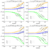 |
Fig. 15. Energy dependent neutrino flavor ratios for L0 = 1050 erg s−1 (left panels) and L0 = 1051 erg s−1 (right panels) for Γ = 100. The top plots correspond to aep = 1 and the bottom ones to aep = 100. The green, orange, and blue curves correspond to the electron, muon, and tau flavor ratios, respectively. The long-dashed, solid, and short-dashed lines refer to the results for ϵB = 0.01, ϵB = 0.1, and ϵB = 1, respectively. The flavor ratios expected without considering losses are indicated with gray dotted lines for the electron flavor, gray long-dashed lines for the muon flavor, and gray long-short dashed lines for the tau flavor. |
 |
Fig. 16. Energy dependent neutrino flavor ratios for L0 = 1050 erg s−1 (left panels) and L0 = 1051 erg s−1 (right panels). Both plots are for Γ = 300. The green, orange, and blue curves correspond to the electron, muon, and tau flavor ratios, respectively. The long-dashed, solid, and short-dashed lines refer to the results for ϵB = 0.01, ϵB = 0.1, and ϵB = 1, respectively. The flavor ratios expected without considering losses are indicated with gray dotted lines for the electron flavor, gray long-dashed lines for the muon flavor, and gray long-short dashed lines for the tau flavor. |
This estimate gives roughly (fe, 0 : fμ, 0 : fτ, 0)∝(1 : 1 : 1) (e.g., Bustamante & Ahlers 2019; Bustamante & Tamborra 2020). Therefore, it can be seen in the mentioned figures that as the neutrino energy increases, the flavor ratios obtained as a result of our full calculation differ more from the expected outcome if losses are neglected. Specifically, the losses discussed (interactions with soft photons, and synchrotron emission) cause the electron flavor ratio to decrease to ≈0.17, the muon ratio to increase up to ≈0.45, and the tau flavor to increase slightly to 0.36. The smooth transition to these values takes place at different energies for the different cases considered.
For L0 = 1051 erg s−1 in particular, the flavor ratios are modified at energies lower than for L0 = 1050 erg s−1, given that the interaction rates are higher in the former cases than in the latter ones. When comparing the top and lower panels of Fig. 15 for Γ = 100, the flavor ratios are shown to be affected at slightly lower energies for aep = 1 than for aep = 100, and it is the interactions with more electron synchrotron radiation that makes the difference.
As discussed above, for Γ = 100 and L0 = 1051 erg s−1, synchrotron cooling of pions and muons become more relevant for higher values of ϵB, and this affects the flavor ratios at lower energies. However, for Γ = 100 and L0 = 1050 erg s−1, synchrotron cooling of muons is only relevant if ϵB = 1, and therefore the cases with lower magnetic fields have similar flavor ratios (long dashed and solid lines in left panels of Fig. 15) and are affected mostly by pion and muon interactions with soft photons.
As for the cases with Γ = 300, the flavor ratios we present in Fig. 16 refer to aep = 1. A different situation arises in the cases with L0 = 1050 erg s−1 shown in the left panel as compared those with L0 = 1051 erg s−1 shown in the right panel. In the former cases, unlike the rest of the cases studied, the corresponding muon distributions extend only to energies below ∼105 GeV (see Fig. 11, middle-left panel), and cooling is mostly dominated by the muon IC process, even for the case of ϵB = 1. In fact, at high energies, the IC cooling rate is in the Klein-Nishina regime (i.e., decreasing with the energy). This implies that increasing ϵB only increases the acceleration rate and therefore the maximum energy of the parent protons and of the produced pions and muons. However, since muons cool more slowly at higher energies in these particular cases (for Γ = 300 and L0 = 1050 erg s−1), the resulting curves for the flavor ratios for low values of ϵB appear slightly more affected by interactions at high energies as compared those for higher magnetic fields. This situation is different for Γ = 300 and L0 = 1051 erg s−1 as wells as in the rest of the cases studied, as the IC cooling of muons does not always dominate if the magnetic field is increased because synchrotron cooling can become important at high energies, and this results in similar flavor ratios to the obtained, for instance, using Γ = 100 and L = 1051 erg s−1.
Given the relatively low number of detected neutrino events of astrophysical origin, a more useful observable to be extracted from experiments may be the flavor ratios of the integrated fluxes. Depending on the energy range of integration, the effects discussed for the energy dependent ratios may also be appreciated in these flavor ratios. If we integrate the fluxes on the neutrino energy above a minimum energy Eν,min
the corresponding flavor ratios can be obtained as
 (52)
(52)
We plot the results in Figs. 17 and 18. The plots show that the effects of cooling can be better observed by concentrating on the neutrino fluxes of the different flavors at energies higher than ∼5 × 10⁵ GeV. Otherwise, the more abundant events of lower energies tend to mask the departure from the standard values of the flavor ratios corresponding to no cooling of the secondary particles.
 |
Fig. 17. Flavor ratios of the integrated fluxes of neutrinos with energy above Eν,min for L0 = 1050 erg s−1 (left panels) and L0 = 1051 erg s−1 (right panels). All plots are for Γ = 100. The top plots correspond to aep = 1 and the bottom ones to aep = 100. The green, orange, and blue curves correspond to the electron, muon, and tau flavor ratios, respectively. The long-dashed, solid, and short-dashed lines refer to the results for ϵB) = 0.01, ϵB = 0.1, and ϵB = 1, respectively. The flavor ratios expected without considering losses are indicated with gray dotted lines for the electron flavor, gray long-dashed lines for the muon flavor, and gray long-short dashed lines for the tau flavor. |
5. Discussion
We have studied in detail the processes leading to the production of high energy neutrinos in CGRBs by making use of steady-state kinetic equations to account for the cooling mechanisms of all the intervening particle populations, namely, electrons, protons, pions, kaons, and muons. Typically, the target photons considered for protons accelerated at the internal shocks are those that escape from the shocked jet head. In the present work, we also considered as targets the synchrotron photons emitted by electrons accelerated at the internal shocks as well as the protons. This implies a rise in the pγ cooling rate only in the cases with a powerful jet L0 = 1051 erg s−1 and Γ = 100, and therefore means a decrease in the maximum proton energy.
We have accounted for IC cooling to obtain the particle distributions of electrons as well as of muons. Pions and kaons produced in pγ interactions are also affected by interactions with the mentioned target of soft photons. We found that these interactions can indeed cause important losses of the mentioned particles and therefore a decrease in the neutrino flux at high energies, even in the cases where the magnetic field is relatively low and no significant losses by synchrotron emission are expected. As a consequence of these losses, the flavor ratios become modified: The electron flavor ratio decreases, and the muon flavor ratio increases. This effect gradually manifests in the energy dependent flavor ratios at high energies, as can be seen in Figs. 15–18, where the different curves represent possible signatures of key physical conditions in the jets of CGRBs, such as the magnetic field, proton-to-electron ratio, Lorentz factor, and the jet power. For these parameters, we adopted typically plausible values, according to several works describing the same general context. In particular, by requiring the flow to be optically thin at the internal shock region and that this region be placed inside the collimation shock, we made sure that the sets of parameters we used would imply shocks that are not mediated by radiation, since that allows for efficient particle acceleration.
 |
Fig. 18. Flavor ratios of the integrated fluxes of neutrinos with energy above Eν,min for L0 = 1050erg s−1 (left panels) and L0 = 1051 erg s−1 (right panels). Both plots are for Γ = 100. The green, orange, and blue curves correspond to the electron, muon, and tau flavor ratios, respectively. The long-dashed, solid, and short-dashed lines refer to the results for ϵB) = 0.01, ϵB = 0.1, and ϵB = 1, respectively. The flavor ratios expected without considering losses are indicated with gray dotted lines for the electron flavor, gray long-dashed lines for the muon flavor, and gray long-short dashed lines for the tau flavor. |
A treatment like the present one could be applied to other compact sources, such as tidal disruption events, where the magnetic field can be high and therefore significant cooling of pions and/or muons can take place (e.g., Senno et al. 2017). The cores of AGN could also be studied by adapting the present model, such as in the case of NGC 1068. As described by Murase (2022), the possible neutrino emission site could be relatively close to the central BH (e.g., in a corona). Another possibility is that it is located further away where protons would be accelerated through shocks generated by a wind from the accretion disk (Lamastra et al. 2016). In this latter case, a sub-gauss magnetic field would yield the expected no-loss flavor ratios, ≈(1 : 1 : 1), while in the case of a corona, the magnetic field would be expected to be higher (possibly B ≳ 1000 G), leading to flavor ratios that would depart from the no-loss result for high neutrino energies.
Still, in order to be able to measure the energy dependent flavor ratios, as well as the flavor ratios of the integrated fluxes for different minimum energies, more observation time and larger neutrino telescopes are necessary. In general, such resources would allow important information on the physical conditions at the neutrino sources to be obtained. In the specific case of CGRBs, these data would help probe the consequences of the generation of such explosive, gamma-ray hidden events, with the physical conditions normally expected for them, providing new clues as to whether these types of sources can indeed contribute significantly to the diffuse neutrino flux.
Acknowledgments
We thank ANCyT and Universidad Nacional de Mar del Plata for their financial support through grants PICT 2021-GRF-T1-00725 and EXA1102/22, respectively.
References
- Atoyan, A. M., & Dermer, C. D. 2003, ApJ, 586, 79 [Google Scholar]
- Baerwald, P., Hümmer, S., & Winter, W. 2012, Astropart. Phys., 35, 508 [NASA ADS] [CrossRef] [Google Scholar]
- Beacom, J. F., Bell, N. F., Hooper, D., et al. 2003, Phys. Rev. D, 68, 093005 [NASA ADS] [CrossRef] [Google Scholar]
- Begelman, M. C., Rudak, B., & Sikora, M. 1990, ApJ, 362, 38 [Google Scholar]
- Block, M. M., & Halzen, F. 2004, Phys. Rev. D, 70, 091901 [NASA ADS] [CrossRef] [Google Scholar]
- Blumenthal, G. R., & Gould, R. J. 1970, Rev. Mod. Phys., 42, 237 [Google Scholar]
- Bosch-Ramon, V., Romero, G. E., & Paredes, J. M. 2006, A&A, 447, 263 [NASA ADS] [CrossRef] [EDP Sciences] [Google Scholar]
- Bromberg, O., Nakar, E., & Piran, T. 2011, ApJ, 739, L55 [NASA ADS] [CrossRef] [Google Scholar]
- Bustamante, M., & Ahlers, M. 2019, Phys. Rev. Lett., 122, 241101 [CrossRef] [Google Scholar]
- Bustamante, M., & Tamborra, I. 2020, Phys. Rev. D, 102, 123008 [NASA ADS] [CrossRef] [Google Scholar]
- Bustamante, M., Beacom, J. F., & Winter, W. 2015, Phys. Rev. Lett., 115, 161302 [NASA ADS] [CrossRef] [Google Scholar]
- Chang, P.-W., Zhou, B., Murase, K., & Kamionkowski, M. 2022, ArXiv e-prints [arXiv:2210.03088] [Google Scholar]
- Dai, L., & Fang, K. 2017, MNRAS, 469, 1354 [NASA ADS] [CrossRef] [Google Scholar]
- Denton, P. B., & Tamborra, I. 2018, ApJ, 855, 37 [NASA ADS] [CrossRef] [Google Scholar]
- Dermer, C. D., & Schlickeiser, R. 2002, ApJ, 575, 667 [NASA ADS] [CrossRef] [Google Scholar]
- Eichler, D., Guetta, D., & Pohl, M. 2010, ApJ, 722, 543 [CrossRef] [Google Scholar]
- Esteban, I., Gonzalez-Garcia, M. C., Maltoni, M., et al. 2020, JCAP, 2020, 178 [Google Scholar]
- Fasano, M., Celli, S., Guetta, D., et al. 2021, JCAP, 2021, 044 [CrossRef] [Google Scholar]
- Fiorillo, D. F. G., van Vliet, A., Morisi, S., et al. 2021, JCAP, 2021, 028 [CrossRef] [Google Scholar]
- Gaisser, T. K. 1990, Cambridge and New York (Cambridge University Press), 53 [Google Scholar]
- Gribov, V. 2023, Strong Interactions of Hadrons at High Energies, by Vladimir Gribov (Cambridge, UK: Cambridge University Press), 2023 [Google Scholar]
- Guetta, D., Rahin, R., Bartos, I., et al. 2020, MNRAS, 492, 843 [CrossRef] [Google Scholar]
- He, H.-N., Kusenko, A., Nagataki, S., et al. 2018, ApJ, 856, 119 [NASA ADS] [CrossRef] [Google Scholar]
- Hjorth, J., & Bloom, J. S. 2012, in Gamma-Ray Burst-Supernova Connection, eds. C. Kouveliotou, R. A. M. J. Wijers, & S. Woosley (Cambridge: Cambridge Univ. Press), 169 [CrossRef] [Google Scholar]
- Hümmer, S., Rüger, M., Spanier, F., et al. 2010, ApJ, 721, 630 [CrossRef] [Google Scholar]
- Hümmer, S., Baerwald, P., & Winter, W. 2012, Phys. Rev. Lett., 108, 231101 [CrossRef] [Google Scholar]
- IceCube Collaboration (Aartsen, M. G., et al.) 2014, Phys. Rev. Lett., 113, 101101 [CrossRef] [PubMed] [Google Scholar]
- IceCube Collaboration (Aartsen, M. G., et al.) 2018, Science, 361, eaat1378 [NASA ADS] [Google Scholar]
- IceCube Collaboration (Abbasi, R., et al.) 2022, Science, 378, 538 [CrossRef] [PubMed] [Google Scholar]
- Kelner, S. R., Aharonian, F. A., & Bugayov, V. V. 2006, Phys. Rev. D, 74, 034018 [Google Scholar]
- Lamastra, A., Fiore, F., Guetta, D., et al. 2016, A&A, 596, A68 [NASA ADS] [CrossRef] [EDP Sciences] [Google Scholar]
- Lipari, P., Lusignoli, M., & Meloni, D. 2007, Phys. Rev. D, 75, 123005 [Google Scholar]
- Loeb, A., & Waxman, E. 2006, JCAP, 2006, 003 [NASA ADS] [CrossRef] [Google Scholar]
- MacFadyen, A. I., Woosley, S. E., & Heger, A. 2001, ApJ, 550, 410 [NASA ADS] [CrossRef] [Google Scholar]
- Madau, P., & Dickinson, M. 2014, ARA&A, 52, 415 [Google Scholar]
- Mészáros, P., & Waxman, E. 2001, Phys. Rev. Lett., 87, 171102 [CrossRef] [Google Scholar]
- Mizuta, A., & Ioka, K. 2013, ApJ, 777, 162 [NASA ADS] [CrossRef] [Google Scholar]
- Murase, K. 2007, Phys. Rev. D, 76, 123001 [NASA ADS] [CrossRef] [Google Scholar]
- Murase, K. 2022, ApJ, 941, L17 [NASA ADS] [CrossRef] [Google Scholar]
- Murase, K., & Ioka, K. 2013, Phys. Rev. Lett., 111, 121102 [NASA ADS] [CrossRef] [Google Scholar]
- Murase, K., & Nagataki, S. 2006, Phys. Rev. D, 73, 063002 [NASA ADS] [CrossRef] [Google Scholar]
- Particle Data Group (Patrignani, C., et al.) 2016, Chin. Phys. C, 40, 100001, 2017 update [NASA ADS] [CrossRef] [Google Scholar]
- Particle Data Group (Workman, R. L., et al.) 2022, Prog. Theor. Exp. Phys., 2022, 083C01 [CrossRef] [Google Scholar]
- Piran, T., Nakar, E., Mazzali, P., & Pian, E. 2019, ApJ, 871, L25 [NASA ADS] [CrossRef] [Google Scholar]
- Petropoulou, M., Giannios, D., & Dimitrakoudis, S. 2014, MNRAS, 445, 570 [CrossRef] [Google Scholar]
- Razzaque, S., Mészáros, P., & Waxman, E. 2004, Phys. Rev. Lett., 93, 181101 [NASA ADS] [CrossRef] [Google Scholar]
- Reusch, S., Stein, R., Kowalski, M., et al. 2022, Phys. Rev. Lett., 128, 221101 [NASA ADS] [CrossRef] [Google Scholar]
- Reynoso, M. M., & Romero, G. E. 2009, A&A, 493, 1 [NASA ADS] [CrossRef] [EDP Sciences] [Google Scholar]
- Rybicki, G. B., & Lightman, A. P. 2004, Radiative Processes in Astrophysics, 189 (Weinheim, Germany: Wiley-VCH) [Google Scholar]
- Senno, N., Murase, K., & Mészáros, P. 2016, Phys. Rev. D, 93, 083003 [NASA ADS] [CrossRef] [Google Scholar]
- Senno, N., Murase, K., & Mészáros, P. 2017, ApJ, 838, 3 [NASA ADS] [CrossRef] [Google Scholar]
- Schlickeiser, R. 2009, MNRAS, 398, 1483 [NASA ADS] [CrossRef] [Google Scholar]
- Stecker, F. W., Done, C., Salamon, M. H., et al. 1991, Phys. Rev. Lett., 66, 2697 [NASA ADS] [CrossRef] [Google Scholar]
- Stein, R., van Velzen, S., Kowalski, M., et al. 2021, Nat. Astron., 5, 510 [NASA ADS] [CrossRef] [Google Scholar]
- Stettner, J. 2019, 36th International Cosmic Ray Conference (ICRC2019), 36, 1017 [NASA ADS] [Google Scholar]
- Wigner, E. P. 1946, Phys. Rev., 70, 15 [NASA ADS] [CrossRef] [Google Scholar]
- Waxman, E., & Bahcall, J. 1997, Phys. Rev. Lett., 78, 2292 [CrossRef] [Google Scholar]
All Tables
All Figures
|
Fig. 1. Schematic view (not to scale) of the jet propagating inside a star. |
| In the text | |
|
Fig. 2. Left panel: optical depth at the internal shock region as a function of the Lorentz factor of the jet for (L0, δt)=(1050 erg s−1, 0.001 s) and (L0, δt)=(1051 erg s−1, 0.01 s), both marked by the black curve, while the blue line corresponds to (L0, δt)=(1050 erg s−1, 0.01 s) and the orange one to (L0, δt)=(1051 erg s−1, 0.001 s). Right panel: positions of the jet head (rh) as a function of the Lorentz factor of the jet for L0 = 1050 erg s−1 and L0 = 1051 erg s−1 marked by long-dashed blue and orange lines, respectively. Solid blue and orange lines correspond to the positions of collimation shock (rcs) for L0 = 1050 erg s−1 and L0 = 1051 erg s−1, respectively. The positions of the internal shocks (ris) for δt = 0.001 s and δt = 0.01 s are indicated with black short-dashed and solid lines, respectively. |
| In the text | |
|
Fig. 3. Cooling and acceleration rates for electrons at the internal shocks of CGRBs for L0 = 1050 erg s−1 and L0 = 1051 erg s−1 in the left and right panels, respectively. Top panels correspond to Γ = 100 and the bottom ones to Γ = 300. The different processes are indicated with the following curves: Dashed lines are for ϵB = 1, solid lines for ϵB = 0.1, and short-dashed lines for ϵB = 0.01. The blue curves refer to acceleration, orange ones to synchrotron, and green ones to external IC. The circles refer to SSC with (aep = 1, ϵB = 0.1) and squares to SSC with (aep = 100, ϵB = 0.1). With dashed gray lines, we also show the auxiliary results used to obtain the SSC rate with the iterative method mentioned in the text. |
| In the text | |
|
Fig. 4. Cooling and acceleration rates for protons at the internal shocks of CGRBs for L0 = 1050 erg s−1 and L0 = 1051 erg s−1 in the left and right panels, respectively. Top panels correspond to Γ = 100 and the bottom ones to Γ = 300. The different processes are indicated with the following curves: dashed lines are for ϵB = 1, solid lines for ϵB = 0.1, and short-dashed lines for ϵB = 0.01. The blue curves refer to acceleration, orange ones to synchrotron, magenta ones to pp interactions, and black ones to adiabatic cooling. With green, we mark the pγ cooling rates corresponding to a target of external photons (solid lines) and to internal pγ interactions with electron synchrotron photons as targets for aep = 1 (long-short dashed lines) and aep = 100 (long-short-short dashed lines). |
| In the text | |
|
Fig. 5. Electron distributions for L0 = 1050 erg s−1 (left panel) and L0 = 1051 erg s−1 (right panel). The top panels correspond to Γ = 100 and the bottom ones to Γ = 300. The green, orange, and blue curves refer to the cases of ϵB = 0.01, ϵB = 0.1, and ϵB = 1, respectively. The dashed curves correspond to aep = 1 and the solid ones to aep = 100. |
| In the text | |
|
Fig. 6. Proton distributions for L0 = 1050 erg s−1 (left panel) and L0 = 1051 erg s−1 (right panel). The top panels correspond to Γ = 100 and the bottom ones to Γ = 300. The green, orange, and blue curves refer to the cases of ϵB = 0.01, ϵB = 0.1, and ϵB = 1, respectively. The dashed curves correspond to aep = 1 and the solid ones to aep = 100. |
| In the text | |
|
Fig. 7. Pion-photon cross section adopted to obtain |
| In the text | |
|
Fig. 8. Pion decay and cooling rates for L0 = 1050 erg s−1 (left panel) and L0 = 1051 erg s−1 (right panel). The top panels correspond to Γ = 100 and the bottom ones to Γ = 300. The blue curves correspond to the pion decay rate, and the green curves represent the πγ interaction with external and internal photons with aep = 1 (dashed lines) and with aep = 100 (solid lines). The pion synchrotron cooling is marked with orange curves for ϵB = 0.01 (short-dashed lines), ϵB = 0.1 (solid lines), and ϵB = 1 (long-dashed lines). The solid black curves mark the adiabatic cooling rate. |
| In the text | |
|
Fig. 9. Muon decay and cooling rates for L0 = 1050 erg s−1 (left panel) and L0 = 1051 erg s−1 (right panel). The top panels correspond to Γ = 100 and the bottom ones to Γ = 300. The blue curves correspond to the muon decay rate, and the green curves represent the IC interaction with external and internal photons with aep = 1 (dashed lines) and with aep = 100 (solid lines). The muon synchrotron cooling is marked with orange curves for ϵB = 0.01 (short-dashed lines), ϵB = 0.1 (solid lines), and ϵB = 1 (long-dashed lines). The solid black curves mark the adiabatic cooling rate. |
| In the text | |
|
Fig. 10. Distributions of pions (top), muons (middle), and charged kaons (bottom) for Γ = 100. The left plots correspond to L0 = 1050 erg s−1 and the right plots to L0 = 1051 erg s−1. The green, orange, and blue curves refer to the cases of ϵB = 0.01, ϵB = 0.1, and ϵB = 1, respectively. The dashed curves correspond to aep = 1 and the solid curves to aep = 100. |
| In the text | |
|
Fig. 11. Distributions of pions (top), muons (middle), and charged kaons (bottom) for Γ = 300. The left plots correspond to L0 = 1050 erg s−1 and the right plots to L0 = 1051 erg s−1. The green, orange, and blue curves refer to the cases of ϵB = 0.01, ϵB = 0.1, and ϵB = 1, respectively. The dashed curves correspond to aep = 1 and the solid ones to aep = 100. |
| In the text | |
|
Fig. 12. Emissivities of muon neutrinos and antineutrinos from the decay of pions (blue curves), muons (orange curves), and kaons (green curves) for L0 = 1050 erg s−1. The dashed curves represent the obtained output if all losses of the parent particles are neglected, while the solid curves mark the results if all the losses discussed are considered. The left plots correspond to aep = 1 and the right plots to aep = 100. |
| In the text | |
|
Fig. 13. Emissivities of muon neutrinos and antineutrinos from the decay of pions (blue curves), muons (orange curves), and kaons (green curves) for L0 = 1051 erg s−1. The dashed curves represent the obtained output if all losses of the parent particles are neglected, while the solid curves mark the results if all the losses discussed are considered. The left plots correspond to aep = 1 and the right plots to aep = 100. |
| In the text | |
|
Fig. 14. Diffuse flux of muon neutrinos and antimuons for L0 = 1050 erg s−1 (top panels) and L0 = 1051 erg s−1 (bottom panels). The results obtained with Γ = 100 and Γ = 300 are shown in the left and right panels, respectively. The green, orange, and blue curves refer to the cases of ϵB = 0.01, ϵB = 0.1, and ϵB = 1, respectively. The dashed curves correspond to aep = 1 and the solid ones to aep = 100. |
| In the text | |
|
Fig. 15. Energy dependent neutrino flavor ratios for L0 = 1050 erg s−1 (left panels) and L0 = 1051 erg s−1 (right panels) for Γ = 100. The top plots correspond to aep = 1 and the bottom ones to aep = 100. The green, orange, and blue curves correspond to the electron, muon, and tau flavor ratios, respectively. The long-dashed, solid, and short-dashed lines refer to the results for ϵB = 0.01, ϵB = 0.1, and ϵB = 1, respectively. The flavor ratios expected without considering losses are indicated with gray dotted lines for the electron flavor, gray long-dashed lines for the muon flavor, and gray long-short dashed lines for the tau flavor. |
| In the text | |
|
Fig. 16. Energy dependent neutrino flavor ratios for L0 = 1050 erg s−1 (left panels) and L0 = 1051 erg s−1 (right panels). Both plots are for Γ = 300. The green, orange, and blue curves correspond to the electron, muon, and tau flavor ratios, respectively. The long-dashed, solid, and short-dashed lines refer to the results for ϵB = 0.01, ϵB = 0.1, and ϵB = 1, respectively. The flavor ratios expected without considering losses are indicated with gray dotted lines for the electron flavor, gray long-dashed lines for the muon flavor, and gray long-short dashed lines for the tau flavor. |
| In the text | |
|
Fig. 17. Flavor ratios of the integrated fluxes of neutrinos with energy above Eν,min for L0 = 1050 erg s−1 (left panels) and L0 = 1051 erg s−1 (right panels). All plots are for Γ = 100. The top plots correspond to aep = 1 and the bottom ones to aep = 100. The green, orange, and blue curves correspond to the electron, muon, and tau flavor ratios, respectively. The long-dashed, solid, and short-dashed lines refer to the results for ϵB) = 0.01, ϵB = 0.1, and ϵB = 1, respectively. The flavor ratios expected without considering losses are indicated with gray dotted lines for the electron flavor, gray long-dashed lines for the muon flavor, and gray long-short dashed lines for the tau flavor. |
| In the text | |
|
Fig. 18. Flavor ratios of the integrated fluxes of neutrinos with energy above Eν,min for L0 = 1050erg s−1 (left panels) and L0 = 1051 erg s−1 (right panels). Both plots are for Γ = 100. The green, orange, and blue curves correspond to the electron, muon, and tau flavor ratios, respectively. The long-dashed, solid, and short-dashed lines refer to the results for ϵB) = 0.01, ϵB = 0.1, and ϵB = 1, respectively. The flavor ratios expected without considering losses are indicated with gray dotted lines for the electron flavor, gray long-dashed lines for the muon flavor, and gray long-short dashed lines for the tau flavor. |
| In the text | |
Current usage metrics show cumulative count of Article Views (full-text article views including HTML views, PDF and ePub downloads, according to the available data) and Abstracts Views on Vision4Press platform.
Data correspond to usage on the plateform after 2015. The current usage metrics is available 48-96 hours after online publication and is updated daily on week days.
Initial download of the metrics may take a while.