| Issue |
A&A
Volume 666, October 2022
|
|
|---|---|---|
| Article Number | A195 | |
| Number of page(s) | 11 | |
| Section | The Sun and the Heliosphere | |
| DOI | https://doi.org/10.1051/0004-6361/202244181 | |
| Published online | 26 October 2022 | |
Automatic detection technique for solar filament oscillations in GONG data
1
Departament Física, Universitat de les Illes Balears, 07122 Palma de Mallorca, Spain
e-mail: This email address is being protected from spambots. You need JavaScript enabled to view it.
2
Institute of Applied Computing & Community Code (IAC 3), UIB, Spain
3
Université Paris-Saclay, CNRS, Institut d’Astrophysique Spatiale, 91405 Orsay, France
Received:
3
June
2022
Accepted:
8
September
2022
Abstract
Context. Solar filament oscillations have been known for decades. The new capabilities of the new telescopes have afforded routine observations of these periodic motions. Oscillations in filaments show key aspects of their structure. A systematic study of filament oscillations over the solar cycle can shed light on the evolution of the prominences.
Aims. This work is a proof of concept that aims to automatically detect and parametrise these oscillations using Hα data from the GONG network of telescopes.
Methods. The proposed technique studies the periodic fluctuations of every pixel of the Hα data cubes. Using the fast Fourier transform, we computed the power spectral density (PSD). We defined a criterion to consider whether it is a real oscillation or a spurious fluctuation. This consisted of considering that the peak in the PSD must be greater than several times the background noise with a confidence level of 95%. The background noise is well fitted to a combination of red and white noise. We applied the method to several observations that were reported in the literature to determine its reliability. We also applied the method to a test case, which was a data set in which the oscillations of the filaments were not known a priori.
Results. The method shows that the filaments contain areas in which the PSD is above the threshold value. The periodicities we obtained generally agree with the values that were obtained by other methods. In the test case, the method detects oscillations in several filaments.
Conclusions. We conclude that the proposed spectral technique is a powerful tool for automatically detecting oscillations in prominences using Hα data.
Key words: Sun: corona / Sun: filaments, prominences / Sun: oscillations
© M. Luna et al. 2022
 Open Access article, published by EDP Sciences, under the terms of the Creative Commons Attribution License (https://creativecommons.org/licenses/by/4.0), which permits unrestricted use, distribution, and reproduction in any medium, provided the original work is properly cited.
This article is published in open access under the Subscribe-to-Open model. This email address is being protected from spambots. You need JavaScript enabled to view it. to support open access publication.
1. Introduction
Solar filaments (also called prominences when seen off-disk) are clouds of dense and cold plasma levitating in the tenuous and hot corona, supported against gravity by their magnetic field. In Hα, they are seen in absorption as dark structures on the solar disk. There are still many unknowns about their nature: how they form, what their structure is, or how they disappear. Prominences form in large magnetic structures called filament channels (FC). These structures are highly non-potential fields appearing above the polarity inversion lines (PIL) of the photosphere. Observational evidence suggests that the FCs are produced by the interaction of the solar magnetic field with the surface and subsurface motions of the sun. These motions are a combination of the large-scale differential rotation, meridional flows, surface diffusion, and smaller-scale vortical motions such as granular and supergranular convection (see the review by Mackay 2014). During the solar cycle, filaments appear in different latitudes and form a pattern. They migrate over a range of latitudes (McIntosh 1972; Minarovjech et al. 1998), showing a butterfly diagram (Coffey & Hanchett 1998) that is similar to the sunspot diagram. This pattern indicates that the structure of the filaments may be related to the large-scale solar field and may evolve over the solar cycle.
Solar prominences are structures that are subject to a wide variety of movements, including oscillations. These periodic motions have been observed sporadically since the beginning of the twentieth century, but new instruments have enabled observations of filament oscillations to become common (see the review by Arregui et al. 2018). The relevance of these periodic motions is that we can apply prominence seismology. This remote diagnostics method aims to determine physical parameters that are difficult to measure by direct means in these magnetised plasma structures. It combines observations of oscillations with theoretical results from the analysis of oscillatory properties of given prominence models. It is necessary to discriminate the restoring force causing the oscillations to apply seismology. The relative direction of the plasma motion to the magnetic field determines which combination of forces is involved. The oscillations can be grouped into transverse, where the restoring force is mostly the Lorentz force (e.g. Hyder 1966; Kleczek & Kuperus 1969; Hershaw et al. 2011), and longitudinal, where the restoring force is mostly gravity along the field lines together with the gas pressure gradients (e.g. Zhang et al. 2012; Luna et al. 2014; Bi et al. 2014). Luna et al. (2017) compared these field properties derived from filament seismology with the characteristics of an inserted flux rope (van Ballegooijen 2004) and found them to agree well in general.
Oscillations in filaments show key aspects of their structure. A systematic study of filament oscillations over the solar cycle can shed light on the evolution of the prominences and their FCs. However, almost all observational studies focus on one or a few episodes. In contrast, Bashkirtsev & Mashnich (1993) studied the oscillations in a considerable number of filaments for the first time. Based on data obtained from the Sayan observatory between 1981 and 1989, the authors reported 38 oscillations events. They found that the main oscillation frequency was between 40 and 80 min, with a mean value of 60 min. In addition, they found a smooth, sinusoidal latitudinal dependence for the observed periods. In our later work (Luna et al. 2018), we did not find a clear relation between the periods or other properties and the filament latitude. The Bashkirtsev & Mashnich (1993) study covered almost a solar cycle, so that their latitudinal dependence might be related to the well-known migration of filaments from the poles toward the equator during the cycle. In Luna et al. (2018) we surveyed prominence oscillations using the GONG network Hα data during 2014 January-June, providing an extensive sample of 196 events close to the solar maximum of cycle 24. We found that the oscillations in filaments had an average period of 58 min, regardless of the oscillation amplitude or filament type. The oscillations were detected by visual inspection of the data. This visual detection has limitations due to the subjective bias introduced in the study. It is difficult to detect relatively high or small frequency oscillations or periodic motions in small filaments. In addition, a study covering years of observations becomes unfeasible because of the large amount of data that is to be analysed by eye.
There are methods that automatically detect and track solar filaments in Hα, as in Gao et al. (2002), Shih & Kowalski (2003), Zharkova et al. (2004), Bernasconi et al. (2005), Fuller et al. (2005), Bonnin et al. (2013) and Hao et al. (2015). These techniques have been used to conduct statistical studies of the properties of filaments, such as Jing et al. (2004), who automatically selected a large number of filament disappearances from a data set of over four years. More recently, Hao et al. (2015) studied the filaments statistically, spanning almost three solar cycles from 1988 to 2013. It is noteworthy that these codes can be used to track the movement of individual filaments. Some of the codes are publicly available, such as in Bonnin et al. (2013) We have tried to use this technique to detect and parametrise oscillations, but the results were unsatisfactory. Although we do not rule out the possibility that these methods may be used to detect oscillations, we decided to investigate another approach, which we present in this study. Filament-tracking techniques can be useful to extract their characteristics, such as length, width, and position, also in parallel to the approach followed in this work.
The paper is organised as follows: In Sect. 2 the automatic technique is described. In Sect. 3 we study synthetic data to understand the intensity fluctuations that are associated with filament oscillations. We also apply the detection method to these data to understand the structures that appear in the spectral analysis. Then in Sect. 4, we apply the method to several events for which oscillations have already been reported to test the efficiency of the method. We also apply the method to data of which it was not known a priori that oscillations were present. Finally, we discuss in Sect. 5 the results and draw our conclusions.
2. Data processing
GONG Hα data are very useful for detecting oscillations in the filaments because the Hα images show the dark filaments that are seen in absorption in sharp contrast to the bright chromosphere around them. In contrast, the SDO EUV images show many highly dynamic structures, such as coronal loops, that make it difficult to detect filaments and their oscillations. However, GONG data have a poorer spatial and temporal resolution, and the quality of the data depends on the conditions of the sky at the time of observation. Despite the limitations of the GONG data, the method is robust enough to efficiently detect oscillations in solar filaments, as we demonstrate below.
This work aims to explore whether a technique that has been applied to detect waves and oscillations from image data cubes (e.g. Terradas et al. 2002; Nakariakov & King 2007; McIntosh et al. 2008; Ireland et al. 2010; Auchère et al. 2014) might be used to detect periodic motions in solar filaments using GONG data. Following (Auchère et al. 2014), the method consists of four steps analysis, namely:
– Detect a region of interest (ROI) and a temporal sequence. Compensate for the solar rotation by remapping to Carrington coordinates by using the drot_map.pro solarsoft routine.
– Calculate the power spectral density (PSD) for each pixel of the ROI.
– Identification of the regions with oscillations according to predefined criteria.
– Parametrisation and storage of the resulting analysis.
With this method, the authors detected regions of the solar corona that oscillate coherently. In these regions, the intensity fluctuations are very clear, with an almost sinusoidal shape, because these fluctuations are probably associated with changes in the density and temperature of the coronal loops on the line of sight of each pixel. In this sense, these fluctuations are intrinsic variations of the emissivity in that portion of the corona. However, the filament oscillations are mainly not intrinsic variations of the intensity of the filament: they are a displacement of part of the dark structure over the solar disk. It is not trivial to determine how the advection of the filament produces the fluctuations of the Hα intensity. To do this, we mimic in section Sect. 3 the oscillation of a filament and the spectral analysis of the intensity fluctuations.
In the second step, we analysed the intensity fluctuations for each heliographic pixel of the ROI. We constructed the PSD using the fast Fourier transform (FFT) of the light curve. In each pixel (i, j), we defined the light-curve signal
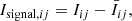 (1)
(1)
where Iij is the original intensity on each pixel, and  is its time average during the temporal sequence that is studied. The time signals given by Eq. (1) were additionally normalised to their standard deviation. The resulting normalised signal was apodized using a Hann window to minimise the effects of the finite duration of the signal on the PSD. We did not apply any detrending or time-differencing to the signal because these operations are prone to introducing detection artefacts when they are combined with an incorrect model of the background noise spectrum (Auchère et al. 2016). The temporal cadence provided by GONG is one minute, which corresponds to a Nyquist frequency of 8.3 mHz. The spectral resolution will depend on the length of the temporal sequence. We have selected time sequences with almost no gaps in the data. When there was a gap, the data were considered zero. We also used the generalised Lomb and Scargle periodogram from Zechmeister & Kürster (2009) and the time-averaged wavelet spectra from Torrence & Compo (1998). This allowed us to compare the benefits and drawbacks of each method. The periodogram is very useful when time sequences with significant gaps are considered, and the wavelets are very useful for events in which the periodicity changes over time. All three techniques produced identical results for the events we considered. Because of its simplicity, we adopted the FFT for this first study to determine whether the oscillation detection technique is feasible. In addition, the FFT calculation is faster than the periodogram or the wavelet.
In the third step, a proper estimation of the expected background power, σij at each frequency and each pixel is necessary to derive the confidence levels. For solar coronal time series, the PSD frequently has two components,
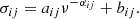 (2)
(2)
The first corresponds to the red noise, which, as we show below, is predominant for ν < 1 mHz. The second component, the constant bij, corresponds to white noise, which is predominant for ν ≥ 1 mHz. Most of the oscillations in filaments we detect have frequencies below 1 mHz. Moreover, events with frequencies higher than 1 mHz correspond to very small regions that are not related to filaments. We therefore conclude that they may be due to false positives or actual oscillations in the solar chromosphere. To make the search more selective, we restricted ourselves to frequencies lower than 1 mHz. However, we fit function (2) Auchère et al. (2014) to the whole frequency range given by the FFT to correctly model the background noise. To perform this fit of the PSD in each pixel, we used the subroutine curvefit.pro from IDL1. In this fit, the data are weighted with the inverse of the square of their standard deviation for each frequency. The standard deviation of the PSD is thus equal to its mean at each frequency (Auchère et al. 2016). However, neither the standard deviation nor the mean value of the PSD is known. We therefore used the inverse of the square of the smoothed PSD with a boxcar average of five points as a weight in the fit. In all cases we considered, we assumed a global confidence level of 95%. For a positive detection, the PSD should be larger than m σij where m is given by
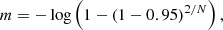 (3)
(3)
where N is the data points in the temporal sequence. As Auchère et al. (2014) pointed out, because a large number of points in the ROI are analysed, the probability of having at least one random point above the confidence level is practically one in the whole region. However, the probability that these random points appear clustered in adjacent pixels above the threshold decreases rapidly with cluster size. We analysed how many pixels appear clustered in adjacent pixels for each frequency and discarded clusters when the number of points was smaller than Nadjacent. We did not find an a priori way to fix the Nadjacent value, but in events with clear oscillation in filaments, several dozen adjacent points oscillate coherently. In future work that will aim to massively automate the detection of oscillations, it will be necessary to provide a criterion for setting Nadjacent. To improve this criterion, we could study which clusters oscillate coherently, considering the relative phase of adjacent pixels, as in McIntosh et al. (2008).
GONG data may have oscillations due to artefacts such as atmospheric turbulence, clouds passing in front of the telescope, or telescope vibrations. These artefacts can produce quasi-periodic variations in intensity over the entire solar disk. This would result in a spike in the PSD that the method could identify as a real oscillation. To identify these possible artefacts, we calculated the average PSD ⟨σ⟩. It was computed by averaging the PSD in each frequency over all the ROI pixels. If there is an actual oscillation in a filament within the ROI, there will not be a pronounced peak in ⟨σ⟩ because the region that oscillates is small in comparison to the ROI and has a small weight on average. However, an artefact will produce fluctuations in a large part of the ROI and produce a clear peak in ⟨σ⟩. In this way, by monitoring ⟨σ⟩, we can detect false oscillations associated with artefacts.
3. Synthetic measurement of prominence oscillations
The Hα images show the filaments in absorption, in contrast with the bright chromosphere. Oscillations are periodic movements of these dark structures on the bright chromosphere. This motion results in the occultation of the light from the chromosphere around the filament. This occultation produces quasi-periodic fluctuations of the intensity in the areas in which the filament moves. However, these fluctuations are not clear sinusoidal patterns, as we show below. To understand the filament oscillations in the Hα images, we schematically reproduced a filament seen in absorption. Figure 1 shows the Hα intensity I(x, y), where the dark structure represents the filament. This intensity is given as I(x, y)=I0 − IGauss(x, y). The background or chromospheric intensity is I0 and IGauss is a 2D Gaussian with an elliptical shape. For simplicity, we assumed that I0 = 1 and that the maximum of IGauss was also 1. We reproduced the oscillation by displacing the IGauss along a line that forms 45° to the x-axis. The period and damping time of the oscillation were set to P = 60 and τ = 75 min, which are values that agree with the observations. The amplitude was set to A = 42 arcsec. The maximum elongation of the filament is shown as dotted isocontours right of the filament at t = P/4. The dotted isocontours at the left also correspond to the maximum elongation, but at t = 3/4P. In Fig. 1 we mark six positions where we probed the intensity fluctuations. These positions are along the trajectory of the periodic motion of the filament. The intensity on each point is shown in the left column of Fig. 2. In the right column, we plot the PSD computed as described in Sect. 2. The intensity fluctuations (left column) from the selected positions show that they do not correspond to clear sinusoidal oscillations. Point 1 corresponds to the centre of the filament (Fig. 1). Figure 2a shows the intensity fluctuates between 0, when the filament is at the equilibrium position, to 1, when the filament is far from this position. During an oscillation cycle, the filament crosses the central position twice, and then the intensity fluctuates twice per period. Figure 2b shows the corresponding PSD. The dashed vertical line shows the oscillation period of 60 min. The dotted vertical lines are half of the oscillation period, 30 min. The PSD has a clear peak at around 30 min, with a maximum value of 13, that is, 20% of the highest PSD value at position 2. Figure 2c shows the intensity at position 2, which is placed around the equilibrium position of the filament at a distance from the filament centre of 14 arcsec. Panel d shows that the PSD has a clear peak centred at 60 min, with a value of 89, which is the highest value measured at the six positions. Position 3 is located at 31 arcsec from the centre, and the filament passes over it at around t = 7 min, before reaching its maximum elongation on the right side, at which time the filament returns to its equilibrium position at approximately t = 22 min. This passage over position 3 is seen as a W shape in the intensity fluctuation of Fig. 2e. Around t = 75 min, the filament again approaches position 3, but due to the damping of the oscillation, the filament centre does not reach this position, and the intensity fluctuations are reduced. Due to the damping of the oscillation, the filament does not pass this point again in the rest of the time sequence. The PSD shows a very wide peak around 65 min, with a power of 23, that is, 30% of the maximum PSD value (Fig. 2f). In position 4, at a distance of 56 arcsec from the centre, the intensity only fluctuates one time (see Fig. 2g) during the first oscillation cycle. The PSD does not show a clear peak (Fig. 2h). In location 5 (Fig. 2i), which is located at 18 arcsec from the centre, the intensity evolution is similar to the case in position 2. The PSD shows a clear peak (Fig. 2j) with a value of 55, that is, 60% of the maximum power. Position 6 is located at 28 arcsec from the centre, that is, the maximum elongation at the left of the equilibrium position. The intensity fluctuation in position 6 (Fig. 2k) is similar to the case of position 4, without a clear peak in its PSD (Fig. 2l). In general, Fig. 2 shows that even though the intensity fluctuations do not show clear harmonic oscillations, the PSD may show clear peaks.
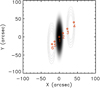 |
Fig. 1. Intensity given by I(x, y) (see text) mimicking a GONG Hα map. The dark area corresponds to the filament seen in absorption. The filament oscillates with a period, P = 60 min, damping time, τ = 75 min, and a direction of 45° with respect to the x-axis. The dotted isocontours at x > 0 show the position of the filament at t = P/4 when the filament reaches its maximum elongation right of the equilibrium position. Similarly, the dotted isocontours at x < 0 show the filament at t = 3/4P when the filament reaches the maximum elongation at the left. The six red circles show the positions along the oscillation trajectory where the intensity fluctuations are studied in detail in Fig. 2. |
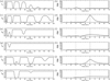 |
Fig. 2. Intensity fluctuations at positions (1) to (6) from Fig. 1 in the left panel from top to bottom. Right panel: PSD of the corresponding intensity fluctuation. |
We reproduced the analysis of the oscillations described in Sect. 2 with the synthetic Hα data. In first step, the ROI was the region shown in Fig. 1. The duration of the event was 200 min, and the temporal cadence was 1 min. For second step, we generated the PSD for every single pixel of the ROI, psdij. The result of the analysis was a data cube consisting of the two spatial coordinates, and the third dimension is the period. To visualise the data, we projected the PSD data cube onto the xy-plane. These projections are slices of the data cube over a range of periods. Within this range of periods, we considered the highest value of the PSD for every single position. Thus, we obtained for each ROI position the highest PSD value in the period range. Panel Fig. 3a shows the projection of the PSD in the plane for the range of periods between 20 and 40 min. This is centred in the middle of the oscillation period, 30 min. As we showed, in the PSD measured in point 1 (Fig. 2b), this arises because the filament passes twice through the equilibrium position in each oscillation cycle. Figure 3b shows the PSD projection in the range of 50−70 min. The PSDs measured in points 2, 3, and 5 (Figs. 2d, f, and j) correspond to this structure. Panel a shows that the 30-min periodicity appears mainly in the central part of the structure, with a maximum PSD of 15.5. Panel b shows the two lobes on both sides of the filament associated with the 60 min oscillation, with a maximum PSD of 115. The 60-min periodicity has a much larger PSD than the 30-min periodicity. As we show below, this will associate the PSD with half of the oscillation period, which is difficult to detect, and in none of the cases have we been able to observe it.
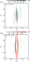 |
Fig. 3. PSD projections for (a) the period range 20−40 min and (b) the period range 50−70 min. See the text for an explanation of how the projection is constructed. The solid isocontours show the filament at its equilibrium position. As in Fig. 1, dotted iscontours show the filament at maximum elongations of the filament right and left of the equilibrium. |
4. Solar filament oscillations
In this section, we apply the technique described in Sect. 2 to GONG observations. We first analyse several events from the catalogue by Luna et al. (2018). In this way, we can compare the results of the new method with those that are known from the catalogue. Second, we use the new technique to detect oscillations in one event that has not been reported before.
4.1. Reference case
We start with the first event of the catalogue on January 1, 2014, as a reference. We describe the method we used in detail. The period of the oscillation is 76 ± 1 min, and the direction of the plasma forms an angle of 16° with respect to the filament spine (see details in the Luna et al. 2018 catalogue). Figure 4 shows a GONG Hα image from the Cerro Tololo telescope of this first event. The white box shows the ROI of 800 × 800 arcsec2 that we analysed. Within the ROI are several filaments, and the white arrow indicates the filament with the oscillations reported in the catalogue (solar object locator SOL2014-01-01T07:54:52L178C097 following the IAU convention suggested by Leibacher et al. 2010). The time sequence we analysed lasts 733 min, from 10:40 UT to 22:53 UT, with a one-minute time cadence. The GONG data have a spatial resolution of approximately 1 arcsec. However, to limit the data volume to be analysed, we reduced the size of the images to one-third by averaging the intensity in squares of 3 × 3 pixels. We used this reduction on all data that we analyse here.
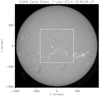 |
Fig. 4. First event, analysed on January 1, 2014. Several filaments are clearly visible as dark structures on the disk. The white box delimits the ROI that was analysed in the first case considered. The arrow indicates the oscillating filament. |
In point 2 of the method (Sect. 2,) we calculated the PSD at each pixel (i, j) of the ROI, psdij. Using Eq. (2), we fitted the background noise level σij on each pixel. In this observation, the number of images is N = 723, then using Eq. (3) and considering a confidence level of 95%, m = 8.9. We define the whitened data cube as psdij(ν)≥m σij(ν) and zero when this condition is not fulfilled. The whitened data appear structured into clusters of different sizes. Clusters with sizes smaller than 20 have a very low PSD value and an unclear oscillation pattern. In this event, we considered Nadjacent = 20, indicating that clusters with fewer than 20 points are not considered (see Sect. 2). Figure 5a represents a cut of the PSD data cube at a given period. The period shown is 80 min, which corresponds to the maximum PSD within the ROI. They are plotted on the Hα map of part of the ROI to identify the oscillating structure. Two regions that we labelled region 1 and 2 are clearly visible. Region 1 has 90 adjacent points, and region 2 has 65 points. Region 1 is the largest and also contains the highest PSD value. These two regions are located on both sides of the filament, one north of the filament, and the other south of it, as we expect from Sect. 3. The solid white line shows the path that was used in the catalogue to study the oscillations. This path was constructed by following the motion of the cold plasma during its oscillation by eye. This indicates that the method has detected filament oscillations in the same region as the visual technique of the catalogue. Figure 5b shows the average light curve of the pixels within each region. In both regions, the oscillatory pattern is very clear. It starts at 13:20 UT, which is t = 160 min since the beginning of the temporal sequence. The cool plasma of the filament moves north from regions 1 to 2. Then in region 1, the intensity grows in the first moments of the oscillation, whereas in region 2, the intensity decreases because the cool plasma occults the chromospheric emission. The oscillation shows clear signs of damping because the fluctuations decrease with time. The detailed parametrisation of the damping will be the subject of future research. Figure 5c shows psdij (solid line) with the highest value shown in Fig. 5a. It corresponds to a point inside region 1 at approximately (x, y)=(−40, −100)″. The red line shows the background noise σij fitted with the Eq. (2) function. The PSD is well fit at all the frequencies. For ν < 1 mHz, the red noise function fits the PSD well. In this frequency range, the white noise has a negligible contribution. For higher frequencies, the PSD is well fit by both red and white noise. However, the white noise dominates, and the curve becomes flat for increasing frequencies. The thick dot-dashed line shows the confidence level threshold 8.9σij computed with Eq. (3). One peak is centred at 80 min, with a power of 49.5σij. This is well above the threshold limit. In the same figure, we have plotted the averaged PSD of the ROI ⟨σ⟩ as a dashed blue line. This does not show peaks, indicating that there are no possible artefacts.
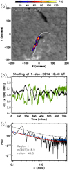 |
Fig. 5. Results of the automatic detection technique in the event of January 1, 2014. In (a) the coloured areas are the cut of the whitened PSD (see text). It is plotted over an Hα map of the region. Two clusters are detected and are labelled region 1 and 2. The period with maximum PSD and its uncertainty is printed at the top of the panel. In (b) the intensity averaged over the whole region 1 (black curve) and the average intensity of region 2 (green curve) are shown. The time is shown on the horizontal axis in minutes starting at 10:40 UT. In (c) the PSD (solid line) with the highest value in the whole ROI is shown, that is, within region 1. The red lines shows the background noise, σij, and the thick dash-dotted line is the detection threshold, 8.9σij, at the given pixel. The dashed blue line shows the noise averaged over the entire ROI, ⟨σ⟩. |
This event shows that the automatic technique works very well. The obtained period of 80 min is similar to the 76 min from the catalogue. The small discrepancy may be due to the poor spectral resolution of the PSD. We can estimate the error in the period determination given by the spectral resolution. In this case, the spectral resolution is 0.023 mHz, and then the period ranges from 72 to 90 min or  min. This estimate can be taken as the first approximation of the period uncertainty (see Gregory 2001; VanderPlas 2018). Considering the period uncertainty, both methods agree well. In addition, the two regions shown in Fig. 5a correspond to the region in which we can visually detect periodic motions that agree with the catalogue findings. We did not detect the PSD distribution with half of the period centred at the filament as in Fig. 3a. It is probably below the detection threshold. This indicates that the intensity fluctuations in individual positions are equivalent to I2, I3, or I5 shown in Figs. 2c, e, and i, respectively, without the half-period signal.
4.2. Oscillations in a tenuous quiescent filament near the limb
The second event we considered is event number 63 from the catalogue on February 13, 2014, with an oscillation period of 103 ± 1 min. It corresponds to a quiescent filament located near the solar limb (SOL2014-02-13T19:31:28L015C123). It is interesting to test the method with this event because the quiescent filament is very faint. As the filament is close to the limb, we also wished to determine the effect of limb darkening on the detectability of the oscillations. Figure 6a shows the ROI we considered. The technique shows three regions labelled 1 to 3 with clear oscillations. A fourth region is labelled 4, which corresponds to the oscillation in a small filament. This oscillation in region 4 can be detected in the GONG data by eye. However, in the following, we focus on the oscillations of the large filament associated with regions 1 to 3. The three areas are above the quiescent filament where the oscillation was reported in event number 63 of the catalogue. In addition, we plot the path of the slit used in the catalogue, which shows that the three areas are above this path. The period is around  min, which agrees with the 103 ± 1 min reported in the catalogue. The uncertainty on the period is very large in this event because in the range of the oscillation period, the resolution in the periods is very low. The resolution can be increased by considering longer temporal sequences combining observations from consecutive telescopes of the network. For example, in this observation, the data come from the Big Bear telescope. We can complete the temporal sequence by using the data from the Mauna Loa telescope or Learmonth, depending on the quality of the data. However, this will be the subject of future research when we will analyse the GONG data in great depth by combining all the telescopes. The averaged light curves in all regions are shown in Fig. 6b. The oscillations are very clear, and the light curves have different phases. The oscillations from regions 1 and 3 are completely out of phase. This indicates that both regions are the lobes at both sides of the filament, as in the previous case or from Fig. 3b. Region 2 is delayed 20 min with respect to region 1. Region 2 also belongs to the same oscillation and the same lobe as region 1. However, it appears that the oscillating plasma moves behind parts of the filament that do not oscillate, producing this pattern. The PSD with the largest amplitude corresponds to region 1 shown in Fig. 6c. In this observation, we considered that we had a detection when the PSD was larger than 8.4σij. In this case, the PSD peak is 12.7σij, that is, above the threshold limit. Both σij and ⟨σ⟩ have similar values in all the frequency domain shown in panel c, indicating that no global oscillations of the GONG images are associated with artefacts (see Sect. 2).
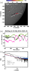 |
Fig. 6. Event of February 13, 2014, as in Fig. 5 with similar panels and annotations. We have detected four regions labelled 1 to 4 in panel a. Panel b: averaged intensity in regions 1 (black), 2 (green), and 3 (pink). The maximum PSD is located inside region 1 and shown in panel c. |
4.3. Very regular oscillation in an active region filament
The third case we analysed is event 58 in an active region filament (SOL2014-02-10T19:01:37L000C109). In the catalogue, we found a very clear oscillatory pattern with a period of 47 ± 1 min. Figure 7a shows that the automated method has found oscillations in the same filament. Moreover, the ROI is devoid of oscillations. As in previous cases, two regions on both sides of the filament are labelled 1 and 2 in the figure. The oscillation period is  min, which agrees very well with the catalogue value. In the panel, we also plot the slit path to construct the time-distance diagram in the catalogue. regions 1 and 2 are not completely above the path. In this case, this discrepancy arises because the path selected in the catalogue is not optimal. If we had considered the path above the two regions, the oscillation in the catalogue time-distance diagram would be even clearer. In panel b the averaged intensity in both regions is shown. Both regions show a very clear oscillatory damped sinusoid pattern. In contrast to previous cases, the two oscillations are not completely in antiphase. The reason might be that the plasma does not oscillate as a solid body as in Sect. 3. Thus, different parts of the filament could oscillate with different phases. The periodogram shows a strong peak of 114.7σij at 0.38 mHz that is much larger than the detectability threshold, 8.8σij.
4.4. Two extreme cases: Events with very small and very large amplitudes
In the next two examples, we analyse two extreme cases. One case has a very small amplitude, and the other is a very energetic event. The first event corresponds to the case with one of the smallest velocity amplitudes in the catalogue. It corresponds to a double oscillation, numbered 189 and 190 in the catalogue, with periods of about 40 min, and the velocity amplitude is just a few km s−1. Figure 8a shows the ROI and the regions in colour in which we detected oscillations. We detected two regions. Region 2 has not been reported in the catalogue. In the two regions, the oscillation period is about 60 min. Region 1 belongs to the oscillation that was reported in the catalogue in the filament (SOL2014-06-16T18:37:17L136C061) north of the sunspot. However, the period is quite different from the reported period. We verified that the data cube contained all frequencies and did not detect a periodicity of 40 min. The discrepancy may arise because in the time-distance diagram of the catalogue, the oscillation has a small amplitude and there is only one cycle. Under these conditions, the method used in the catalogue probably failed. We plot the path we used to track the oscillation in the catalogue. The path and region 1 are close, but not exactly in the same part of the filament. This may also contribute to the discrepancy between the two methods. Region 2 belongs to a small filament (SOL2014-06-16T18:37:17L132C071) located south of the sunspot. In panel b the averaged light curves in each of the regions are shown. Periodic fluctuations are clear in both curves. Panel c shows that the PSD has a clear peak above the background noise. The PSD peak is 23.8σij, which is well above the detection threshold of 8.9σij. Visual inspection of the GONG data shows the oscillation in the two filaments, which corroborates the efficiency of the method presented here.
The following event corresponds to a very energetic case where its oscillations have not been described in the catalogue or the literature. However, the oscillation is one of the clearest and has one of the largest amplitudes we have seen in the GONG and SDO/AIA data. These oscillations are associated with a flare produced by a two-step eruption on March 15, 2015. The eruption was reported by Chandra et al. (2017). In Fig. 9a we show the ROI and the two regions in which the technique has detected the oscillations. The two areas lie around the filament (SOL2015-03-15T08:19:18L211C105) and correspond to a  -min oscillation. The averaged light curves in the two regions clearly show the periodic fluctuations. Panel c shows a clear peak in the PSD that is 25.4σij, which is much larger than the detection threshold, 8.7σij. Two additional peaks are visible at 0.7 mHz and 0.95 mHz above the detection threshold. In this case, the oscillation of the filament is a combination of three different periodicities.
The ⟨σ⟩ does not show peaks in the two cases presented in this section (Figs. 8c and 9c). This indicates that there are no possible artefacts, as discussed in Sect. 2. However, in both cases, ⟨σ⟩ has a steeper slope than σij for increasing frequency values. In addition, ⟨σ⟩ increases abruptly for ν > 2 mHz, becoming much larger than σij. In the case of June 16, 2014, we found that the PSD contributes strongly at high frequencies in the plage region located at the centre of Fig. 8a and also from the spot shown in the same panel. The contribution from the plage and the spot has a strong influence on the average PSD ⟨σ⟩ over the whole ROI. Similarly, for March 15, 2015, the high frequencies from the plage and flaring region that is visible as bright area centred at (x, y)=(400, −250) arcsec in Fig. 9a contribute strongly.
4.5. Test case
In the latter case, we applied the detection method to a GONG temporal sequence of February 9, 2022. On that day, the solar disk contained some filaments, and it is not known a priori whether they include oscillations. We analysed the whole disk and detected oscillations in five regions. Figure 10a shows the part of the ROI where the oscillations have been detected. The panel is not equivalent to the previous cases, for which we plotted a cut of the data volume in a given frequency. In contrast, we projected the PSD in the ROI similar to Fig. 3. The periods ranged from 49 to 89 min. Within this period range, we obtained the highest PSD value for every position of the xy-plane. Regions 1 and 4 are above the same filament (SOL2022-02-09T02:26:30L340C057) that is located north of the active region, AR12941. Region 2 is associated with the oscillations in a filament (SOL2022-02-09T02:26:30L334C074) located south of the same AR. In the three regions, we can identify the oscillations from the GONG data very well by eye, and the intensity fluctuations are clear in panel b. The largest PSD is inside region 1 and is plotted in panel c. It is 12.1σij, that is, above the 8.9σij of the detection threshold. The oscillation is less clear in region 3. A visual inspection of the Hα data shows a small dark area that seems to be associated with repetitive surges just north of the sunspot. Panel b (pink curve) shows the quasi-periodic fluctuations of the intensity in the region. The intensity fluctuations appear to increase in amplitude from 100 to 520 min after the initial time, and the fluctuations cease shortly after. Finally, the oscillation in region 5 corresponds to the periodic motion in an intermediate filament (SOL2022-02-09T02:26:30L018C074) located between AR12940 (not shown) and AR12941. In this case, the oscillation is also visually identified in the data, although it is not as clear as in regions 1 and 2. Panel b shows the periodic fluctuation of the intensity in the region. This case shows that the technique can detect true oscillations that are not easily detectable by eye, but also quasi-periodic fluctuations that are probably not associated with actual oscillations. In the future, we should define criteria to distinguish real prominence oscillations or quasi-periodic fluctuations.
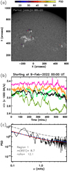 |
Fig. 10. Event of February 9, 2022. In contrast to Fig. 5, we show in panel a several PSD projections in a given range from 49 to 89 min. Panel b: the averaged intensity in 1 (black), 2 (green), 3 (blue), 4 (orange), and 5 (red) are plotted. The periods for the regions 1 to 5 are |


5. Discussion and conclusions
We explored whether a spectral technique for the automatic detection of oscillations in solar filaments can be used. This technique studies the periodic intensity fluctuations in each pixel of the considered data. For each pixel, the PSD was constructed using the FFT. Detection was considered when a peak in the PSD was several times above the background noise with a confidence level over 95%. The background noise was well fitted to a combination of red and white noise. The proposed method has already been successfully applied to other observations, but so far not to Hα data.
Filament oscillations consist of periodic displacements of the cold filament plasma over the solar disk. These oscillations do not have to produce intrinsic oscillations of their emission. However, the periodic motion of the cold plasma produces periodic occultations of the emission from the chromosphere below and around the filament. This allows us to apply the spectral technique for our purpose. To understand how this technique is applied, we reproduced the oscillation detection process by mimicking the oscillations of filaments in Hα. We analysed the PSD of each pixel in the domain and found that around the filament, the PSD has a strong peak centred on the oscillation period.
We applied the new technique to some events that were reported in the Luna et al. (2018) catalogue. In this way, we were able to verify the reliability of the new technique. The first case study corresponded to the first event in the catalogue. We detected a strong signal around the same filament as in the catalogue and it had a similar period. Moreover, the regions in which a PSD above the detection threshold is detected are on the path used in the catalogue to track the oscillations. The intensity in regions with a positive detection shows clear periodic fluctuations. The second case we considered is a faint filament near the limb where the chromospheric intensity decreases as the edge of the disk is approached (limb-darkening effect). We found that the method detects oscillations in the same region of the filament as in the catalogue and with a similar period. The third case consisted of a very clear oscillation with many oscillation cycles. In this case, the visual oscillation tracking method and the automatic oscillation tracking method disagreed. The regions with a positive oscillation are not aligned with the slit used in the catalogue. This suggests that the new method is more accurate in determining the regions with periodic motions. We then showed two opposite cases: one with a very small amplitude, and one with a very large amplitude. The first case belonged to the catalogue, but the second case had not been described in the literature, but its oscillations are very clear. In the ROI of the first case, we detected the oscillation described in the catalogue, but we also found periodic movements in a second filament in the same area. However, the oscillation period does not coincide in the two techniques. Furthermore, the regions in which we detected the oscillation are not on the slit used in the catalogue. This might indicate that the slit used was not optimal for tracking the oscillation, explaining the discrepancy with the automatic method. The opposite case corresponds to a large oscillation after a partial eruption and a flare. The method detects this oscillation perfectly. Finally, we considered an arbitrary day and analysed the whole solar disk, of which we did not know whether it contained oscillations. We detected five zones with oscillations between 51 and 69 min. All oscillations correspond to periodic filament motions, except for one, which corresponds to a quasi-periodically recurring surge-like activity. Future research will investigate a method that allows us to distinguish between quasi-periodic fluctuations in intensity associated with repetitive jet activity from actual oscillations in filaments, for instance.
In this first study, we focused on frequencies lower than 1 mHz because for frequencies above 1 mHz, many small scattered areas pass the detection criterion. These may be due to false positives or actual chromospheric fluctuations. In future research, we will investigate filament oscillations at higher frequencies in more detail.
This work consists of a proof of concept for automatically detecting oscillations in solar filaments. We proved that the presented spectral method detects these periodic motions very reliably, and that it can be used to analyse solar data on a massive scale. However, for this end, modifications to the method as presented in Sect. 2 need to be made. The ROI should consist of the entire Sun and not just of a portion of the solar disk. In addition, we should combine the data from all telescopes of the GONG network to have long temporal sequences. This will allow us to have a higher spectral resolution and also to be able to study very long period oscillations such as very long periods of several dozen hours (Foullon et al. 2004; Efremov et al. 2016). This study has shown that it is possible to detect oscillation in filaments and their periods. In future research, we will study the possibility of parametrising the damping time, the velocity amplitude, and the direction of oscillation. These are only part of the challenges that will have to be addressed in order to develop an automated code for the large-scale detection and parametrisation of oscillations in solar filaments. With a code like this, we might be able to understand how the oscillations in solar filaments evolve over several solar cycles using data from GONG or any other Hα data repository. This research is also relevant for the planned next-generation GONG (ngGONG, Hill et al. 2019) network of telescopes.
Details of this subroutine can be found in https://www.l3harrisgeospatial.com/docs/curvefit.html. This routine computes the non-linear least-squares fit of function Eq. (2). It is calculated iteratively until the χ2 varies by a specified amount or the maximum number of iterations is reached. These are given by the parameters TOL and ITMAX, which we set to 10−4 and 1000, respectively.
Acknowledgments
M.L. acknowledges support through the Ramón y Cajal fellowship RYC2018-026129-I from the Spanish Ministry of Science and Innovation, the Spanish National Research Agency (Agencia Estatal de Investigación), the European Social Fund through Operational Program FSE 2014 of Employment, Education and Training and the Universitat de les Illes Balears. This publication is part of the R+D+i project PID2020-112791GB-I00, financed by MCIN/AEI/10.13039/501100011033. The authors also acknowledge support from the International Space Sciences Institute (ISSI) via team 413 on “Large-Amplitude Oscillations as a Probe of Quiescent and Erupting Solar Prominences”.
References
- Arregui, I., Oliver, R., & Ballester, J. L. 2018, Liv. Rev. Sol. Phys., 15, 3 [Google Scholar]
- Auchère, F., Bocchialini, K., Solomon, J., & Tison, E. 2014, A&A, 563, A8 [NASA ADS] [CrossRef] [EDP Sciences] [Google Scholar]
- Auchère, F., Froment, C., Bocchialini, K., Buchlin, E., & Solomon, J. 2016, ApJ, 825, 110 [Google Scholar]
- Bashkirtsev, V. S., & Mashnich, G. P. 1993, A&A, 279, 610 [NASA ADS] [Google Scholar]
- Bernasconi, P. N., Rust, D. M., & Hakim, D. 2005, Sol. Phys., 228, 97 [NASA ADS] [CrossRef] [Google Scholar]
- Bi, Y., Jiang, Y., Yang, J., et al. 2014, ApJ, 790, 100 [NASA ADS] [CrossRef] [Google Scholar]
- Bonnin, X., Aboudarham, J., Fuller, N., Csillaghy, A., & Bentley, R. 2013, Sol. Phys., 283, 49 [Google Scholar]
- Chandra, R., Filippov, B., Joshi, R., & Schmieder, B. 2017, Sol. Phys., 292, 81 [NASA ADS] [CrossRef] [Google Scholar]
- Coffey, H. E., & Hanchett, C. D. 1998, ASP Conf. Ser., 150, 488 [NASA ADS] [Google Scholar]
- Efremov, V. I., Parfinenko, L. D., & Solov’ev, A. A. 2016, Sol. Phys., 291, 3357 [NASA ADS] [CrossRef] [Google Scholar]
- Foullon, C., Verwichte, E., & Nakariakov, V. M. 2004, A&A, 427, L5 [NASA ADS] [CrossRef] [EDP Sciences] [Google Scholar]
- Fuller, N., Aboudarham, J., & Bentley, R. D. 2005, Sol. Phys., 227, 61 [NASA ADS] [CrossRef] [Google Scholar]
- Gao, J., Wang, H., & Zhou, M. 2002, Sol. Phys., 205, 93 [NASA ADS] [CrossRef] [Google Scholar]
- Gregory, P. C. 2001, AIP Conf. Proc., 568, 557 [NASA ADS] [CrossRef] [Google Scholar]
- Hao, Q., Fang, C., Cao, W., & Chen, P. F. 2015, ApJS, 221, 33 [NASA ADS] [CrossRef] [Google Scholar]
- Hershaw, J., Foullon, C., Nakariakov, V. M., & Verwichte, E. 2011, A&A, 531, A53 [NASA ADS] [CrossRef] [EDP Sciences] [Google Scholar]
- Hill, F., Hammel, H., Martinez-Pillet, V., et al. 2019, BAAS, 51, 110 [NASA ADS] [Google Scholar]
- Hyder, C. 1966, Z. Astrophys., 63, 78 [NASA ADS] [Google Scholar]
- Ireland, J., Marsh, M. S., Kucera, T. A., & Young, C. A. 2010, Sol. Phys., 264, 403 [NASA ADS] [CrossRef] [Google Scholar]
- Jing, J., Yurchyshyn, V. B., Yang, G., Xu, Y., & Wang, H. 2004, ApJ, 614, 1054 [Google Scholar]
- Kleczek, J., & Kuperus, M. 1969, Sol. Phys., 6, 72 [NASA ADS] [CrossRef] [Google Scholar]
- Leibacher, J., Sakurai, T., Schrijver, C. J., & van Driel-Gesztelyi, L. 2010, Sol. Phys., 263, 1 [NASA ADS] [CrossRef] [Google Scholar]
- Luna, M., Knizhnik, K., Muglach, K., et al. 2014, ApJ, 785, 79 [NASA ADS] [CrossRef] [Google Scholar]
- Luna, M., Su, Y., Schmieder, B., Chandra, R., & Kucera, T. A. 2017, ApJ, 850, 143 [NASA ADS] [CrossRef] [Google Scholar]
- Luna, M., Karpen, J., Ballester, J. L., et al. 2018, ApJS, 236, 35 [NASA ADS] [CrossRef] [Google Scholar]
- Mackay, D. H. 2014, Solar Prominences, 415th edn. (Cham: Solar Prominences), 355 [Google Scholar]
- McIntosh, P. S. 1972, Rev. Geophys., 10, 837 [NASA ADS] [CrossRef] [Google Scholar]
- McIntosh, S. W., De Pontieu, B., & Tomczyk, S. 2008, Sol. Phys., 252, 321 [NASA ADS] [CrossRef] [Google Scholar]
- Minarovjech, M., Rybanský, M., & Rušin, V. 1998, Sol. Phys., 177, 357 [NASA ADS] [CrossRef] [Google Scholar]
- Nakariakov, V. M., & King, D. B. 2007, Sol. Phys., 241, 397 [NASA ADS] [CrossRef] [Google Scholar]
- Shih, F. Y., & Kowalski, A. J. 2003, Sol. Phys., 218, 99 [NASA ADS] [CrossRef] [Google Scholar]
- Terradas, J., Molowny-Horas, R., Wiehr, E., et al. 2002, A&A, 393, 637 [NASA ADS] [CrossRef] [EDP Sciences] [Google Scholar]
- Torrence, C., & Compo, G. P. 1998, Bull. Am. Meteorol. Soc., 79, 61 [Google Scholar]
- van Ballegooijen, A. A. 2004, ApJ, 612, 519 [NASA ADS] [CrossRef] [Google Scholar]
- VanderPlas, J. T. 2018, ApJS, 236, 16 [Google Scholar]
- Zechmeister, M., & Kürster, M. 2009, A&A, 496, 577 [CrossRef] [EDP Sciences] [Google Scholar]
- Zhang, Q. M., Chen, P. F., Xia, C., & Keppens, R. 2012, A&A, 542, A52 [NASA ADS] [CrossRef] [EDP Sciences] [Google Scholar]
- Zharkova, V. V., Aboudarham, J., Zharkov, S. I., et al. 2004, AGU Fall Meeting Abstracts, SH52A–04 [Google Scholar]
All Figures
|
Fig. 1. Intensity given by I(x, y) (see text) mimicking a GONG Hα map. The dark area corresponds to the filament seen in absorption. The filament oscillates with a period, P = 60 min, damping time, τ = 75 min, and a direction of 45° with respect to the x-axis. The dotted isocontours at x > 0 show the position of the filament at t = P/4 when the filament reaches its maximum elongation right of the equilibrium position. Similarly, the dotted isocontours at x < 0 show the filament at t = 3/4P when the filament reaches the maximum elongation at the left. The six red circles show the positions along the oscillation trajectory where the intensity fluctuations are studied in detail in Fig. 2. |
| In the text | |
|
Fig. 2. Intensity fluctuations at positions (1) to (6) from Fig. 1 in the left panel from top to bottom. Right panel: PSD of the corresponding intensity fluctuation. |
| In the text | |
|
Fig. 3. PSD projections for (a) the period range 20−40 min and (b) the period range 50−70 min. See the text for an explanation of how the projection is constructed. The solid isocontours show the filament at its equilibrium position. As in Fig. 1, dotted iscontours show the filament at maximum elongations of the filament right and left of the equilibrium. |
| In the text | |
|
Fig. 4. First event, analysed on January 1, 2014. Several filaments are clearly visible as dark structures on the disk. The white box delimits the ROI that was analysed in the first case considered. The arrow indicates the oscillating filament. |
| In the text | |
|
Fig. 5. Results of the automatic detection technique in the event of January 1, 2014. In (a) the coloured areas are the cut of the whitened PSD (see text). It is plotted over an Hα map of the region. Two clusters are detected and are labelled region 1 and 2. The period with maximum PSD and its uncertainty is printed at the top of the panel. In (b) the intensity averaged over the whole region 1 (black curve) and the average intensity of region 2 (green curve) are shown. The time is shown on the horizontal axis in minutes starting at 10:40 UT. In (c) the PSD (solid line) with the highest value in the whole ROI is shown, that is, within region 1. The red lines shows the background noise, σij, and the thick dash-dotted line is the detection threshold, 8.9σij, at the given pixel. The dashed blue line shows the noise averaged over the entire ROI, ⟨σ⟩. |
| In the text | |
|
Fig. 6. Event of February 13, 2014, as in Fig. 5 with similar panels and annotations. We have detected four regions labelled 1 to 4 in panel a. Panel b: averaged intensity in regions 1 (black), 2 (green), and 3 (pink). The maximum PSD is located inside region 1 and shown in panel c. |
| In the text | |
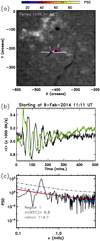 |
Fig. 7. Event of February 9, 2014, as in Fig. 5, with similar panels and annotations. |
| In the text | |
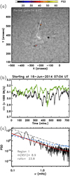 |
Fig. 8. Event of June 16, 2014, as in Fig. 5, with similar panels and annotations. |
| In the text | |
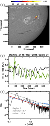 |
Fig. 9. Event of March 15, 2015, as in Fig. 5, with similar panels and annotations. |
| In the text | |
|
Fig. 10. Event of February 9, 2022. In contrast to Fig. 5, we show in panel a several PSD projections in a given range from 49 to 89 min. Panel b: the averaged intensity in 1 (black), 2 (green), 3 (blue), 4 (orange), and 5 (red) are plotted. The periods for the regions 1 to 5 are |
| In the text | |
Current usage metrics show cumulative count of Article Views (full-text article views including HTML views, PDF and ePub downloads, according to the available data) and Abstracts Views on Vision4Press platform.
Data correspond to usage on the plateform after 2015. The current usage metrics is available 48-96 hours after online publication and is updated daily on week days.
Initial download of the metrics may take a while.