| Issue |
A&A
Volume 595, November 2016
|
|
|---|---|---|
| Article Number | A97 | |
| Number of page(s) | 7 | |
| Section | Numerical methods and codes | |
| DOI | https://doi.org/10.1051/0004-6361/201628751 | |
| Published online | 07 November 2016 | |
Research Note
T-PHOT version 2.0: Improved algorithms for background subtraction, local convolution, kernel registration, and new options
1 INAF–Osservatorio Astronomico di Roma, via Frascati 33,
00078 Monte Porzio Catone ( RM), Italy
e-mail: This email address is being protected from spambots. You need JavaScript enabled to view it.
2 SUPA (Scottish Universities Physics
Alliance), Institute for Astronomy, University of Edinburgh, Royal Observatory,
Edinburgh,
EH9 3HJ,
UK
3 Space Telescope Science Institute,
3700 San Martin
Drive, Baltimore,
MD
21218,
USA
4 Laboratoire AIM-Paris-Saclay,
CEA/DSM/Irfu – CNRS – Université Paris Diderot, CEA-Saclay,
pt courrier 131,
91191
Gif-sur-Yvette,
France
5 Observatoire astronomique de
Strasbourg, Université de Strasbourg, CNRS, UMR 7550, 11 rue de l’Université,
67000
Strasbourg,
France
Received:
20
April
2016
Accepted:
30
August
2016
Abstract
Aims. We present the new release – version 2.0 – of t-phot, a publicly available software package developed to perform PSF-matched, prior-based, multiwavelength deconfusion photometry of extragalactic fields.
Methods. New features included in the code are presented and discussed: background estimation, fitting using position dependent kernels, flux prioring, diagnostical statistics on the residual image, exclusion of selected sources from the model and residual images, and individual registration of fitted objects.
Results. The new options improve on the performance of the code, allowing for more accurate results and providing useful aids for diagnostics.
Key words: methods: data analysis / techniques: photometric / galaxies: photometry
© ESO 2016
1. Introduction
t-phot (Merlin et al. 2015, hereafter M15) is a public software package designed to perform precision photometry on a low-resolution extragalactic image (LRI) using the information given by priors obtained from a higher resolution image (HRI) of the same field. It was developed and released within the Astrodeep project and it is being increasingly used in the community.
This paper presents the features included in the new publicly released version 2.0. The new package is downloadable from the Astrodeep webpage1. Version 2.0 is back-compatible with the last publicly released version, 1.5.11: the installation procedure and the required input have not changed, and old parameter files can be used. All the features present in v1.5.11 are still available.
A detailed description of t-phot and its capabilities and limitations is given in M15; for the reader’s convenience, we give a brief review of the code philosophy here. Starting from spatial and morphological information on a list of priors, t-phot produces low-resolution models (templates) by means of a convolution kernel, and assigns to each normalized model a multiplicative factor to match the global observed flux in the LRI. This technique is particularly useful for disentangling the contribution to the observed flux coming from blended sources.
The search for the fluxes in the LRI is performed solving a linear system  (1)where I contains the pixel values of the fluxes in the LRI, Pi are the normalized fluxes of the templates for the N objects in the region of the LRI being fitted, and Fi are the multiplicative scaling factors for each object. In physical terms, Fi represents the flux of each object in the LRI (i.e. it is the unknown to be determined).
In the Gaussian additive noise regime (a condition typically satisfied in astrophysical infrared images), the best fit for the unknown fluxes can be derived by minimizing a χ2 statistic, ![Mathematical equation: \begin{equation} \chi^2=\sum_{m,n}\left[ \frac{I(m,n)-M(m,n)}{\sigma(m,n)} \right]^2 , \end{equation}](/articles/aa/full_html/2016/11/aa28751-16/aa28751-16-eq7.png) (2)where m and n are the pixel indexes,
(2)where m and n are the pixel indexes,  (3)and σ is the rms value in the pixel.
In practice, the problem is reshaped into a matrix equation  (4)where the matrix A contains the coefficients PiPj/σ2, F is the vector of the unknowns, and B is a vector given by IiPi/σ2 terms.
The system can be solved at once on the whole image or on portions of the LRI, either determined by an arbitrary regular grid of cells, or with cells centred on each object.
t-phot can process simultaneously three types of priors: real cutouts from a high-resolution image, analytical 2D models, and point-like sources. The pipeline of t-phot consists of “stages”, each of which performs a well-defined task; the best results are usually obtained by performing two runs (pass1 and pass2), the second run using local convolution kernels, registered after the X,Y local shifts are determined during pass1.
The pipeline can be specified using the keyword order in the parameter file. The simplest way to run the code is to simply set order standard for a typical pass1 run, and order standard2 for the subsequent pass2 run.
In v2.0 it is also possible to set order FIRstandard and/or order FIRstandard2 for typical far-infrared (FIR) processing, i.e. using only point-like priors and PSF2-shaped templates for the fit. If this option is used, any input given for high-resolution real priors or model priors will be ignored.
t-phot outputs a catalogue with IDs, positions, measured fluxes, and corresponding uncertainties for each source in the priors list, as well as a number of useful diagnostics (flags, covariance indexes, residual maps, etc.).
2. New options available in T-PHOT v2.0
The new features available in v2.0 are the following:
-
Background estimation: two methods are introduced, the global subtraction of a constant fitted value and the local fit of individual “background templates”. See Sect. 2.1.
-
Local/individual kernel fitting: it is now possible to associate a different kernel with each source to optimize the fit, coping with local variations of the PSFs. See Sect. 2.2.
-
Individual source registration (dance): after the fit, a refinement of the spatial registration of the objects is performed on an individual basis rather than on arbitrary regions. See Sect. 2.3.
-
Flux prioring: the flux of selected sources or all sources can be constrained to a given desired value within a chosen uncertainty limit. See Sect. 2.4.
-
Statistics on the residuals: the output includes a new text file with diagnostic statistics for each source, based on the residual image produced after the fit. See Sect. 2.5.
-
rms uncertainty threshold to exclude sources from the fit: if the central pixel of a source has rms uncertainty exceeding a chosen value, the source will be excluded from the fitting procedure. See Sect. 2.6.
-
Model building with selected sources: it is possible to build a model image (and a residual image) including only a selection of sources from the priors list. See Sect. 2.7.
A new technical option is the command line input: it is now possible to enter parameters from the command line, over-writing the ones specified in the parameter file. Keywords and corresponding values can be entered by typing -<keyword> <value> after the parameter file specification.
A revision of the code architecture in the sources registration and in the convolution stages has also been performed to make the workflow simpler and better organized. The low-resolution templates are now registered on the fly during the second pass convolution stage, and the second pass local kernels are no longer stored on the local hard disk.
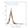 |
Fig. 1 Global background subtraction. One thousand fake sources have been injected on a SCUBA-2 450 μm map, previously background subtracted with the t-phot routine, and the output measured flux for each source has been compared to the input “true” flux. The average is consistent with zero, within the uncertainties of the method. See Bourne et al. (2016). |
The new options are described in detail in the documentation included in the software tarball. In the following sections we present them in summary.
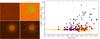 |
Fig. 2 Left panels: simulated images to test the local background estimation techinque. Top left: HRI (FWHM = 0.2″); top right: LRI (FWHM = 1.66″; many sources are too faint to be seen); bottom left: artificially added background (on a different scale and with density contours to enhance visibility); bottom right: background estimated by t-phot, after smoothing with a Gaussian kernel. The plot on the right shows the relative error on the measured flux versus the input true magnitude: tiny yellow dots refer to the whole catalogue in a run with no background enhancement; in the run with the enhanced background but without applying the local background estimation method, many sources (black dots) have largely overestimated fluxes (their positions are shown with green marks in the LRI image, second sub-panel of the left image: they are all gathered where the artificial background is stronger). When applying the local background estimation method, the measured fluxes of these sources are much more reasonable (red dots), and close to their values measured in the run without background enhancement (empty blue squares). |
2.1. Background estimation
t-phot v2.0 can estimate a constant background from the whole image, and/or a local background for each source, during the fitting stage.
2.1.1. Global background
To estimate a constant global background, the keyword fitbackground must be set to true in the parameter file. An additional constant term will be added to the linear system matrix. It is important to note the following:
-
It is strongly recommended to use this option only when fitting the whole image at once. If a cell method is used for the fit, the local background will be computed for each cell and this might lead to unphysical patchy solutions.
-
The value of the background will only be output in the log file of the fitting routine, while the model and residual images will not be background subtracted; to visualize the results, the user must subtract the fitted value from the residual image. On the contrary, the fitted fluxes in the output catalogue obviously take into account the background and must not be corrected.
The global background subtraction has been tested extensively in Herschel and SCUBA2 images in single-fit mode. Figure 1 shows the results of one such test in which a SCUBA-2 450 μm image of the COSMOS-CANDELS field was fitted with a prior catalogue from the K band and IRAC 3.6 μm priors (Bourne et al. 2016). To test the background subtraction, a single fake source was added to the image and prior catalogue at a random position, with its flux drawn from a uniform logarithmic distribution between 0.01−10 mJy. t-phot was used to extract the fluxes of all priors including the artificial source, and the procedure was repeated 1000 times. The distribution of the difference between the measured and true fluxes of the artificial sources in the 450 μm image is shown in Fig. 1. By fitting a Gaussian profile to this histogram, we find that the mean offset is a small fraction of the output uncertainties, while the width of the distribution is marginally larger than the measurement uncertainties by a factor of 1.3. We found no significant trend in this flux offset as a function of input flux. The mean of the unbinned data (fmeas − ftrue) is 0.15 ± 0.18 mJy, while the variance-weighted mean is −0.02 ± 0.05 mJy; both are consistent with zero, indicating that background subtraction is successful and fluxes over a wide range can be recovered reliably without bias.
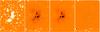 |
Fig. 3 Local background subtraction. Left to right: original LRI image (Abell 2744 Ks band, mosaic by G. Brammer); residual after standard fitting; background model, built as a smoothed collage of the fitted local background templates; residual after fitting on background subtracted image. |
2.1.2. Local background
If the background is expected to vary strongly within the fitted region, it might be useful to fit a locally varying background. To this end, t-phot can create an additional, flat fake object for each real source, and add it to the priors list; these fake background objects are then fit simultaneously with the real objects, providing an estimation of a possible flat background flux. To switch on this option, the keyword fit_loc_bkgd in the paramfile must be set to an integer, giving the offset to be assigned to the IDs of the fake background templates (it should be larger than the maximum ID of real objects).
It is important to note the following:
-
The fitted value for these background templates may scatter significantly from a reliable average value. Therefore, only an average of all the background templates will give a reasonable estimate of the background.
-
Including these templates will change the covariance matrix and hence affect the error budget of the measured fluxes.
To cope with these issues, it is strongly recommended to build a model background image including only the fitted background templates (see Sect. 2.7), to subtract it from the real LRI (possibly after some smoothing), and to repeat the fit in standard mode on this background subtracted LRI.
Figure 2 shows the results of a test on a simulated set of images. An artificial, Gaussian-shaped background light has been added to the original LRI; fluxes have been measured with a standard run, and then with a run including the local background subtraction algorithm. While in the first case the fluxes of the sources in the region where the background has been enhanced turn out to be largely wrong, the new method allows for a good recovery of their true flux.
Figure 3 shows the effect of the application of this technique for the fit of the Abell 2744 cluster in the Ks band, as described in Merlin et al. (2016).
 |
Fig. 4 From left to right: original LRI (a portion of GOODS-South observed with IRAC at 3.6 μm, mosaic by R. McLure); residual after standard fitting using a single convolution kernel; residual after fitting using a different individual kernel for each source (Sect. 2.2), tailored on the basis of the positional angles of the pointings used to build the mosaic (global background subtraction has also been applied, see Sect. 2.1); residual after including the individual kernel registration (Sect. 2.3; in the last two panels, blue boxes highlight regions where the improvement using this technique is evident). |
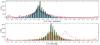 |
Fig. 5 Individual registration of sources (dance). Top panel: histogram of the difference between true and measured shifts in the X direction in a simulated image; red: region-based dance (v1.5.11); blue bars: individual dance, without smoothing; green bars: individual dance with smoothing on a fixed Rneigh area; black bars: individual dance with smoothing on a fixed number Nneigh = 100 of neighbouring sources. Bottom panel: histogram of the measured shifts in the X direction in a simulated image where no shifts were applied; red bars: region-based dance (v1.5.11); green bars: individual dance with smoothing on a fixed Rneigh area; black bars: individual dance with smoothing on a fixed number Nneigh = 100 of neighbouring sources; dashed red: region-based dance on the image with shifts, for reference. See text for more details. |
2.2. Local or individual kernel fitting
Point Spread Functions can vary substantially in different regions of the same image. Provided this variation can be characterized quantitatively, it is possible to input a list of individual convolution kernels or PSFs, each one to be associated with one prior (of course, it is possible to link the same kernel to more than one prior, e.g. characterizing regions rather than individual sources). t-phot will process each object using the corresponding convolution kernel.
An example of the effectiveness of this approach is depicted in Fig. 4. The first three panels show, from left to right: the LRI (in this case, a portion of the GOODS-South field in the IRAC 3.6 μm band); the residuals obtained using a single PSF on the whole image; and the residuals obtained using individual kernels for each source (created averaging model PSFs, each one rotated accordingly to the position angle of the observations and weighted by the exposure time of each pointing3), plus the global background subtraction technique described in Sect. 2.1. It is clear that the individual kernel fitting yields much more accurate results.
2.3. Individual source registration
After the fitting stage, a spatial registration procedure (the dance stage) can be performed to mitigate the effects of possible local astrometric imprecisions. The procedure is based on a cross-correlation between the model collage and the original LRI. In v1.5.11, this cross-correlation is made on the basis of a predefined subdivision of the LRI in a regular grid of cells; on the contrary, in v2.0 the process is performed on a source-by-source basis. The cross-correlation is made on the pixels belonging to the area of the low-resolution template of each source (or on a minimum user-defined area if the template is too small). To avoid local numerical divergencies, the final values of the X,Y shifts are smoothed computing a weighted mean including ≃ Nneigh nearest neighbouring sources, or all the neighbours within a given Rneigh. The weight of each neighbour is computed as the ratio between the peak value of its own correlation function (the higher this value, the more reliable the evaluation of the shift for this source) and the distance from the central object.
While slightly more time consuming, this method allows for a much more precise determination of the spatial shifts needed to register each model, as it is evident from the third and fourth panels of Fig. 4 (blue boxes highlight the regions where the improvement is more evident). We performed a test to make sure that this method increases the accuracy while not introducing biases. We produced two simulated LRIs from the same input catalogue: the first one with each source shifted by a known amount in the X and Y directions, and the second without shifts. In the upper panel of Fig. 5 we plot the histograms of the difference between the true and the measured shifts in the X direction on the first LRI, with four methods: the region-based dance (used in v1.5.11, red histogram), and the individual dance without smoothing (blue bars) and with smoothing (green bars: smoothing on all neighbours within Rneigh; black bars: smoothing on the closest Nneigh = 100 neighbours). The smoothed individual dance with fixed Nneigh yields the best results, reducing spurious large shifts and increasing the number of sources with a good estimation of the true shift. Similar results are obtained for the Y shifts. In the bottom panel of Fig. 5 we show the measured shifts in the X direction on the second LRI, where no true shift is present: again, the smoothed individual dance (green and black bars) yields more accurate results than the region-based dance (red bars; the red dashed histogram is, for reference, the measured shift in the first LRI). Similar results are obtained for the Y shifts. Finally, to make sure that the new method does not introduce biases in the photometry, we checked that the measured fluxes are consistent with their true values. We did so on the second LRI of the previous test (see Fig. 6) and on a new image with only PSF-shaped objects displaced on a regular grid to avoid contaminations and mismatches. We find that while a straightforward individual registration can, in some cases, slightly affect the accuracy of the photometry, because the noise can lead the local cross-correlation process (depending on the extension of the objects under consideration), virtually no bias is introduced when the smoothing approach is adopted.
From all these tests, it turns out that the optimal registration technique depends on the particular case under analysis. In the considered idealized simulations, where the artificial shifts have been added analytically and follow a smooth pattern, the accuracy in determining the true shifts keeps increasing as Nneigh increases, although if no shifts are present an even better result is obtained by smoothing on a fixed area rather than keeping the number of neighbours constant. However, in real cases the pattern of shifts is generally chaotic, likely with abrupt discontinuities over the observed fields. This makes it difficult to foresee a general good-practice standard. We therefore choose to leave Nneigh as a free input parameter, also including the possibility of smoothing over fixed Rneigh.
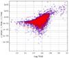 |
Fig. 6 Individual registration of sources (dance). Absolute difference between true and measured fluxes in the same simulated image as in Fig. 5 where no shifts are present, before (red dots) and after (blue open circles) applying the individual smoothed registration procedure. See text for more details. |
2.4. Flux prioring
In v2.0 it is possible to perform the fitting routine enabling an option to constrain measured fluxes around a chosen fixed value, with a given allowed uncertainty. This can be useful to constrain sources on the basis of a SED-fitted predicted flux in the measurement passband.
To this end, the matrix A and the vector B of the linear system in Eq. (4) are modified as follows:
-
Bi becomes
 , and
, and -
when i = j, the element Aij changes to
 ,
,
where fi is the estimated flux for source i that has to be used as prior for that source, and σi is its associated uncertainty (this procedure is known as L2 regularization).
To enable this “flux prioring” option, a text file must be prepared in which each source is associated with its prior flux and the relative allowed uncertainty, along with a flag indicating whether the prior must be used or not.
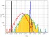 |
Fig. 7 Results of a series of tests on a simulated image using the flux prioring method. Different histograms refer to separate runs on the same LRI. The yellow bars are the fluxes f measured without imposing any constraints (run A). In all the other runs, a given set of flux priors with a corresponding uncertainty has been given to all the sources, and the histograms show the measured fluxes: fconstr,B = f ± 0.5 (cyan), fconstr,C = 10 ± 0.1 (blue), fconstr,D = 10-3 ± 0.1 (red), fconstr,E = 10-3 ± 10-4 (black). We note that (i) the run without constraints (yellow) yields very similar results to the run where each source has its “true” input flux as prior (B, cyan); (ii) in the other runs the flux is forced to a fixed value which is retrieved consistently with the allowed uncertainties. See text for more details. |
Figure 7 shows the results of a test on a simulated image, on which five different runs were performed:
-
(i) a reference run A without constraints on the fluxes (yellow histogram);
-
(ii) a run B in which the fluxes of all sources were constrained to be consistent with their input “true” fluxes within σconstr = 0.5 (cyan);
-
and three other runs in which the measured fluxes were forced to arbitrary values with different error budgets:
-
(iii) fconstr = 10 and σconstr = 0.1 (blue, run C),
-
(iv) fconstr = 10-3 and σconstr = 0.1 (red, run D), and
-
(v) fconstr = 10-3 and σconstr = 10-5 (black, run E).
-
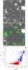 |
Fig. 8 Original LRI (upper) and residual after fitting (centre) on a FORS2 R-band image; the sources with green squares correspond to the ones selected by eye as deviating from the global distribution in the bottom plot (the blue open circles; red dots are the whole catalogue), where the standard deviation of the residual of each source has been plotted against the absolute value of the mean of the residual (both values have been taken from the output file from t-phot). |
2.5. Statistics on the residual image
A file containing diagnostic statistics for each source, computed on the residual image, can be output from this version. A file will be produced listing mean, median, rms, and kurtosis computed on the pixels of the residual image belonging to the template model. Also, the same values computed only on an inner and an outer regions (the limit between such regions is defined as the radius at which the flux of the template is half the value of the peak) will be computed.
Figure 8 shows how this feature can be a useful aid for analysing the reliability of the results, e.g. to single out sources with high standard deviation in the pixel fluxes on the residual image.
2.6. Exclusion of high rms uncertainty sources from the fit
In v2.0 it is possible to include a keyword in the parameter file to exclude from the fit sources belonging to regions with exceedingly large rms uncertainty values (e.g. flawed regions or artificially enlarged borders). If the value of the keyword rmscheck is set equal to some crms> 0, a check is performed on the rms map and sources having their central pixels with a value higher than crms are automatically excluded from the list of the sources to be fitted. These sources will be re-included in the final output catalogue, with “99.0” and zero values in the relevant fields.
2.7. Model and residual images production excluding selected sources
After the fitting procedure, t-phot produces a final catalogue with the determined fluxes, and two diagnostic images: a model image obtained producing a collage with the low-resolution templates of the sources, each one put at its correct position and multiplied by its fitted flux; and a residual image, obtained by subtracting the model image from the original LRI.
In v2.0 it is possible to feed the code with a file containing a list of IDs from the HRI catalogue to be excluded from the model image (they will therefore remain unsubtracted in the residual image). This feature can be used to isolate objects removing neighbours, or to remove bright foreground sources leaving background objects.
3. Conclusions
We have presented and discussed the new options implemented in t-phot v2.0: background estimation, fitting using individual kernels, individual registration of fitted objects, flux prioring, statistics on the residual image, and exclusion of selected sources from the model and residual images.
The code is publicly available for downloading from the Astrodeep website.
Point spread function.
We neglected shear and rescaling of the PSFs in this case.
The input σ for each source gives an estimate of the reliability of the corresponding prior, as an additional term in the system matrix, but the measured flux is not unavoidably forced to stay within its limit. This is the reason why many sources end up having measured fluxes with a scatter larger than 3σ.
References
- Bourne, N., Dunlop, J. S., Merlin, E., et al. 2016, MNRAS, submitted [arXiv:1607.04283] [Google Scholar]
- Merlin, E., Fontana, A., Ferguson, H. C., et al. 2015, A&A, 582, A15 [NASA ADS] [CrossRef] [EDP Sciences] [Google Scholar]
- Merlin, E., Amorín, R., Castellano, M., et al. 2016, A&A, 590, A30 [NASA ADS] [CrossRef] [EDP Sciences] [Google Scholar]
All Figures
|
Fig. 1 Global background subtraction. One thousand fake sources have been injected on a SCUBA-2 450 μm map, previously background subtracted with the t-phot routine, and the output measured flux for each source has been compared to the input “true” flux. The average is consistent with zero, within the uncertainties of the method. See Bourne et al. (2016). |
| In the text | |
|
Fig. 2 Left panels: simulated images to test the local background estimation techinque. Top left: HRI (FWHM = 0.2″); top right: LRI (FWHM = 1.66″; many sources are too faint to be seen); bottom left: artificially added background (on a different scale and with density contours to enhance visibility); bottom right: background estimated by t-phot, after smoothing with a Gaussian kernel. The plot on the right shows the relative error on the measured flux versus the input true magnitude: tiny yellow dots refer to the whole catalogue in a run with no background enhancement; in the run with the enhanced background but without applying the local background estimation method, many sources (black dots) have largely overestimated fluxes (their positions are shown with green marks in the LRI image, second sub-panel of the left image: they are all gathered where the artificial background is stronger). When applying the local background estimation method, the measured fluxes of these sources are much more reasonable (red dots), and close to their values measured in the run without background enhancement (empty blue squares). |
| In the text | |
|
Fig. 3 Local background subtraction. Left to right: original LRI image (Abell 2744 Ks band, mosaic by G. Brammer); residual after standard fitting; background model, built as a smoothed collage of the fitted local background templates; residual after fitting on background subtracted image. |
| In the text | |
|
Fig. 4 From left to right: original LRI (a portion of GOODS-South observed with IRAC at 3.6 μm, mosaic by R. McLure); residual after standard fitting using a single convolution kernel; residual after fitting using a different individual kernel for each source (Sect. 2.2), tailored on the basis of the positional angles of the pointings used to build the mosaic (global background subtraction has also been applied, see Sect. 2.1); residual after including the individual kernel registration (Sect. 2.3; in the last two panels, blue boxes highlight regions where the improvement using this technique is evident). |
| In the text | |
|
Fig. 5 Individual registration of sources (dance). Top panel: histogram of the difference between true and measured shifts in the X direction in a simulated image; red: region-based dance (v1.5.11); blue bars: individual dance, without smoothing; green bars: individual dance with smoothing on a fixed Rneigh area; black bars: individual dance with smoothing on a fixed number Nneigh = 100 of neighbouring sources. Bottom panel: histogram of the measured shifts in the X direction in a simulated image where no shifts were applied; red bars: region-based dance (v1.5.11); green bars: individual dance with smoothing on a fixed Rneigh area; black bars: individual dance with smoothing on a fixed number Nneigh = 100 of neighbouring sources; dashed red: region-based dance on the image with shifts, for reference. See text for more details. |
| In the text | |
|
Fig. 6 Individual registration of sources (dance). Absolute difference between true and measured fluxes in the same simulated image as in Fig. 5 where no shifts are present, before (red dots) and after (blue open circles) applying the individual smoothed registration procedure. See text for more details. |
| In the text | |
|
Fig. 7 Results of a series of tests on a simulated image using the flux prioring method. Different histograms refer to separate runs on the same LRI. The yellow bars are the fluxes f measured without imposing any constraints (run A). In all the other runs, a given set of flux priors with a corresponding uncertainty has been given to all the sources, and the histograms show the measured fluxes: fconstr,B = f ± 0.5 (cyan), fconstr,C = 10 ± 0.1 (blue), fconstr,D = 10-3 ± 0.1 (red), fconstr,E = 10-3 ± 10-4 (black). We note that (i) the run without constraints (yellow) yields very similar results to the run where each source has its “true” input flux as prior (B, cyan); (ii) in the other runs the flux is forced to a fixed value which is retrieved consistently with the allowed uncertainties. See text for more details. |
| In the text | |
|
Fig. 8 Original LRI (upper) and residual after fitting (centre) on a FORS2 R-band image; the sources with green squares correspond to the ones selected by eye as deviating from the global distribution in the bottom plot (the blue open circles; red dots are the whole catalogue), where the standard deviation of the residual of each source has been plotted against the absolute value of the mean of the residual (both values have been taken from the output file from t-phot). |
| In the text | |
Current usage metrics show cumulative count of Article Views (full-text article views including HTML views, PDF and ePub downloads, according to the available data) and Abstracts Views on Vision4Press platform.
Data correspond to usage on the plateform after 2015. The current usage metrics is available 48-96 hours after online publication and is updated daily on week days.
Initial download of the metrics may take a while.