Fig. 5.
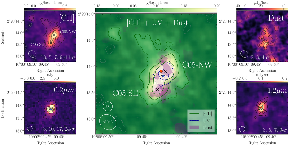
Download original image
Multiwavelength cutout postage stamps toward CRISTAL-05. (a) Left top panel: ALMA [C II] moment-0 map (non-JvM corrected). The overlaid black contours correspond to the 3, 5, 7, 9, and 11-σ[C II] levels. The white ellipse indicates the beam size of 0.33″×0.27″. (b) Left bottom panel: HST F140W rest-frame UV (0.2μm) continuum image. The overlaid contours correspond to the 3, 10, 17, and 24-σUV levels. The white circle indicates the 0.2″ point spread function. The peak emission is marked as a blue star. (c) Right top panel: non-JvM-corrected ALMA rest-frame 160 μm dust continuum image. The overlaid contours correspond to the 2, 3, 4-σ160. The white ellipse indicates the beam size of 0.33″×0.27″, the same as the [C II] moment-0 resolution. (d) Right lower panel: JWST F770W (1.2 μm) rest-frame near-infrared image. The black contours correspond to 3, 5, 7, and 9σ1.2. The peak emission is marked as a red circle. (e) Central panel: Non-JvM-corrected ALMA [C II] moment-0 map in the background, similar to the left top panel. We display the [C II] peak emission of C05-NW and C05-SE components as black crosses (based on Figure 2). The overlaid green contours correspond to the 3, 6, and 9 σ[C II] levels. The blue dashed lines represent the HST/F140W map, for the 7 and 20σ significance levels. The filled areas correspond to the 160 μm dust continuum emission for the 2, 3, and 4 σ significance levels.
Current usage metrics show cumulative count of Article Views (full-text article views including HTML views, PDF and ePub downloads, according to the available data) and Abstracts Views on Vision4Press platform.
Data correspond to usage on the plateform after 2015. The current usage metrics is available 48-96 hours after online publication and is updated daily on week days.
Initial download of the metrics may take a while.