| Issue |
A&A
Volume 674, June 2023
|
|
|---|---|---|
| Article Number | A179 | |
| Number of page(s) | 23 | |
| Section | Cosmology (including clusters of galaxies) | |
| DOI | https://doi.org/10.1051/0004-6361/202346189 | |
| Published online | 23 June 2023 | |
CHEX-MATE: Constraining the origin of the scatter in galaxy cluster radial X-ray surface brightness profiles
1
INAF, IASF-Milano, Via A. Corti 12, 20133 Milano, Italy
e-mail: iacopo.bartalucci@inaf.it
2
INAF – Osservatorio Astronomico di Trieste, Via Tiepolo 11, 34131 Trieste, Italy
3
IFPU – Institute for Fundamental Physics of the Universe, Via Beirut 2, 34151 Trieste, Italy
4
Université Paris-Saclay, Université Paris Cité, CEA, CNRS, AIM, 91191 Gif-sur-Yvette, France
5
Department of Astronomy, University of Geneva, ch. d’Écogia 16, 1290 Versoix, Switzerland
6
DiSAT, Università degli Studi dell’Insubria, Via Valleggio 11, 22100 Como, Italy
7
Astronomy Unit, Department of Physics, University of Trieste, Via Tiepolo 11, 34131 Trieste, Italy
8
Università degli studi di Roma ‘Tor Vergata’, Via della ricerca scientifica 1, 00133 Roma, Italy
9
INAF, Osservatorio di Astrofisica e Scienza dello Spazio, Via Piero Gobetti 93/3, 40129 Bologna, Italy
10
Dipartimento di Fisica e Astronomia, Universitá di Bologna, Via Gobetti 92/3, 40121 Bologna, Italy
11
INAF, Osservatorio Astronomico di Brera, Via E. Bianchi 46, 23807 Merate, Italy
12
Dipartimento di Fisica, Sapienza Università di Roma, Piazzale Aldo Moro 5, 00185 Roma, Italy
13
INFN, Sezione di Bologna, viale Berti Pichat 6/2, 40127 Bologna, Italy
14
Department of Astrophysical Sciences, Princeton University, Princeton, NJ 08544, USA
15
Laboratoire d’Astrophysique de Marseille, Aix-Marseille Université, CNRS, CNES, Marseille, France
16
Institut d’Astrophysique de Paris, CNRS, Sorbonne Université, 98 bis Bd Arago, 75014 Paris, France
17
Jodrell Bank Centre for Astrophysics, Department of Physics and Astronomy, School of Natural Sciences, The University of Manchester, Manchester M13 9PL, UK
18
Center for Astrophysics, Harvard & Smithsonian, 60 Garden Street, Cambridge, MA 02138, USA
19
HH Wills Physics Laboratory, University of Bristol, Tyndall Ave, Bristol BS8 1TL, UK
20
IRAP, Université de Toulouse, CNRS, CNES, UPS, 9 av. du Colonel Roche, BP44346, 31028 Toulouse Cedex 4, France
21
Dipartimento di Fisica, Università degli Studi di Milano, Via G. Celoria 16, 20133 Milano, Italy
Received:
20
February
2023
Accepted:
18
April
2023
We investigate the statistical properties and the origin of the scatter within the spatially resolved surface brightness profiles of the CHEX–MATE sample, formed by 118 galaxy clusters selected via the SZ effect. These objects have been drawn from the Planck SZ catalogue and cover a wide range of masses, M500 = [2 − 15]×1014 M⊙, and redshift, z = [0.05, 0.6]. We derived the surface brightness and emission measure profiles and determined the statistical properties of the full sample and sub-samples according to their morphology, mass, and redshift. We found that there is a critical scale, R ∼ 0.4R500, within which morphologically relaxed and disturbed object profiles diverge. The median of each sub-sample differs by a factor of ∼10 at 0.05R500. There are no significant differences between mass- and redshift-selected sub-samples once proper scaling is applied. We compare CHEX–MATE with a sample of 115 clusters drawn from the THE THREE HUNDRED suite of cosmological simulations. We found that simulated emission measure profiles are systematically steeper than those of observations. For the first time, the simulations were used to break down the components causing the scatter between the profiles. We investigated the behaviour of the scatter due to object-by-object variation. We found that the high scatter, approximately 110%, at R < 0.4R500YSZ is due to a genuine difference between the distribution of the gas in the core of the clusters. The intermediate scale, R500YSZ = [0.4−0.8], is characterised by the minimum value of the scatter on the order of 0.56, indicating a region where cluster profiles are the closest to the self-similar regime. Larger scales are characterised by increasing scatter due to the complex spatial distribution of the gas. Also for the first time, we verify that the scatter due to projection effects is smaller than the scatter due to genuine object-by-object variation in all the considered scales.
Key words: galaxies: clusters: intracluster medium / galaxies: clusters: general / X-rays: galaxies: clusters
© The Authors 2023
 Open Access article, published by EDP Sciences, under the terms of the Creative Commons Attribution License (https://creativecommons.org/licenses/by/4.0), which permits unrestricted use, distribution, and reproduction in any medium, provided the original work is properly cited.
This article is published in open access under the Subscribe to Open model. Subscribe to A&A to support open access publication.
1. Introduction
Galaxy clusters represent the ultimate manifestation of large-scale structure formation. Dark matter comprises 80% of the total mass in a cluster and is the main actor of the gravitation assembly prcoess (Voit 2005; Allen et al. 2011; Borgani & Kravtsov 2011). This influences the prevalent baryonic component represented by a hot and rarefied plasma that fills the cluster volume, that is, the intracluster medium (ICM). This plasma’s properties are affected by the individual assembly history and ongoing merging activities. The study of its observational properties is thus fundamental to study how galaxy clusters form and evolve. The ideal tool for investigating this component is X-ray observations, as the ICM emits in this band via thermal Bremsstrahlung.
The radial profiles of the X-ray surface brightness (SX) of a galaxy cluster and the derived emission measure (EM) are direct probes of the plasma properties. These two quantities can be easily measured in the X-ray band and have played a crucial role in the characterisation of the ICM distribution since the advent of high spatial resolution X-ray observations (e.g., Vikhlinin et al. 1999). Neumann & Arnaud (1999) and Neumann & Arnaud (2001) compared SX profiles with expectations from theory to test the self-similar evolution scenario and investigate the relation between the cluster luminosity and its mass and temperature. Arnaud et al. (2001) tested the self-similarity of the EM profiles of 25 clusters in the [0.3–0.8] redshift range, finding that clusters evolve in a self-similar scenario, which deviates from the simplest models because of the individual formation history. The SX and EM profiles have been used to investigate the properties of the outer regions of galaxy clusters, both in observations (e.g., Vikhlinin et al. 1999; Neumann 2005; Ettori & Balestra 2009) and in a suite of cosmological simulations (see e.g., Roncarelli et al. 2006). These regions are of particular interest because of the plethora of signatures from the accretion phenomena, but they are hard to observe because of their faint signal. More recent works based on large catalogues (see e.g., Rossetti et al. 2017; Andrade-Santos et al. 2017) have determined the effects of the X-ray versus the Sunyaev Zel’Dovich (SZ; Sunyaev & Zeldovich 1980) selection by studying the concentration of the surface brightness profiles in the central regions of galaxy clusters. Finally, the SX radial profile represents the baseline for any study envisaging to derive the thermodynamical properties of the ICM, such as the 3D spatial distribution of the gas (Sereno et al. 2012, 2017, 2018). This information can be combined with the radial profile of the temperature, and together, they can be used to derive quantities such as the entropy (see, e.g., Voit et al. 2005), pressure, and mass of the galaxy cluster under the assumption of hydrostatic equilibrium (Ettori et al. 2013; Pratt et al. 2022).
In this paper, we used the exceptional data quality of the 118 galaxy clusters from the Cluster HEritage project with XMM-Newton – Mass Assembly and Thermodynamics at the Endpoint of structure formation (CHEX-MATE1, PI; S. Ettori and G.W. Pratt). Specifically, we investigate for the first time the statistical properties of the X-ray surface brightness and emission measure radial profiles of a sample of galaxy clusters observed with unprecedented and homogeneous deep XMM-Newton observations. The sample, being based on the Planck catalogue, is SZ selected and thus predicted to be tightly linked to the mass of the cluster (e.g., Planelles et al. 2017; Le Brun et al. 2018), and hence it should yield a minimally biased sample of the underlying cluster population.
Our analysis is strengthened by the implementation of the results from a mass-redshift equivalent sample from cosmological and hydrodynamical simulations of the THE THREE HUNDRED collaboration (Cui et al. 2016). We used a new approach to understand the different components of the scatter, considering the population (i.e. cluster-to-cluster) scatter and the single object scatter inherent to projection effects.
In Sect. 2, we present the CHEX–MATE sample. In Sects. 3 and 4, we describe the methodology used to prepare the data and the derivation of the radial profiles of the CHEX–MATE and numerical datasets, respectively. In Sect. 5, we discuss the shape of the profiles. In Sect. 6, we present the scatter within the CHEX–MATE sample. In Sect. 7, we investigate the origin of the scatter of the EM profiles, and finally in Sect. 8, we discuss our results and present our conclusions.
We adopted a flat Λ-cold dark matter cosmology with ΩM(0)=0.3, ΩΛ = 0.7, H0 = 70 km Mpc s−1, E(z)=(ΩM(1 + z)3 + ΩΛ)1/2, and ΩM(z)=ΩM(0)(1 + z)3/E(z)2 throughout. The same cosmology was used for the numerical simulations, except for h = 0.6777. Uncertainties are given at the 68% confidence level (i.e. 1σ). All the fits were performed via χ2 minimisation. We characterised the statistical properties of a sample by computing the median and the 68% dispersion around it. This dispersion was computed by ordering the profiles according to their χ2 with respect to the median and by considering the profile at ±34% around it. We use natural logarithm throughout the work except for where we state otherwise.
2. The CHEX–MATE sample
2.1. Definition
This work builds on the sample defined for the XMM-Newton heritage programme accepted in AO-17. We briefly report the sample definition and selection criteria here that are detailed in CHEX-MATE Collaboration (2021). The scientific objective of this programme is to investigate the ultimate manifestation of structure formation in mass and time by observing and characterising the radial thermodynamical and dynamic properties of a large, minimally biased and S/N-limited sample of galaxy clusters. This objective is achieved by selecting 118 objects from the Planck PSZ2 catalogue (Planck Collaboration XXVII 2016), applying a S/N threshold of 6.5 in the SZ identification, and folding the XMM-Newton visibility criteria.
The key quantity  , defined as the mass enclosed within the radius
  of the cluster where its average total matter density is 500 times the critical density of the Universe, is measured by the Planck Collaboration using the MMF3 SZ detection algorithm detailed in Planck Collaboration XXVII (2016). This algorithm measures the YSZ flux associated to each detected cluster, and it is used to derive the
  using the M500–YSZ relation calibrated in Arnaud et al. (2010), assuming self-similar evolution. We note that while the clusters’ precise mass determination is one of the milestones of the multi-wavelength coverage of the CHEX-MATE programme, in this paper we consider the radii and mass values directly from the Planck catalogue. The impact of this choice will be discussed in Sect. 5.5.
The CHEX–MATE sample is split in two sub-samples according to the cluster redshift.
Tier 1 provides a local sample of 61 objects in the [0.05–0.2] redshift range in the northern sky (i.e. Dec > 0), and their  span the [2 − 9]×1014 M⊙ mass range. These objects represent a local anchor for any evolution study.
Tier 2 offers a sample of the massive clusters,  in the [0.2–0.6] redshift range. These objects represent the culmination of cluster evolution in the Universe.
The distribution in the mass and redshift plane of the CHEX–MATE sample and its sub-samples are shown in Fig. 1. The exposure times of these observations were optimised to allow the determination of spatially resolved temperature profiles at least up to R500 with a precision of 15%.
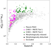 |
Fig. 1. Distribution of the clusters published in the PSZ2 Planck catalogue (Planck Collaboration XXVII 2016) in the mass-redshift plane. The masses in the Planck catalogue were derived iteratively from the M500–YSZ relation calibrated using hydrostatic masses from XMM-Newton; they were not corrected for the hydrostatic equilibrium bias. The magenta and green points represent the Tier 1 and Tier 2 clusters of the CHEX–MATE sample, respectively (CHEX-MATE Collaboration 2021). The triangles and squares identify the morphologically relaxed and disturbed clusters, respectively, which were identified according to the classification scheme in Campitiello et al. (2022). The two red crosses identify the clusters excluded from the analysis of this work. |
The clusters PSZ2 G028.63+50.15 and PSZ2 G283.91+73.87 were excluded from the analysis presented in this work since their radial analysis could introduce large systematic errors without increasing the statistical quality of the sample. Indeed, the former system presents a complex morphology (see Schellenberger et al. 2022 for a detailed analysis), and it has a background cluster at z = 0.38 within its extended emission. The latter is only ∼30 arcmin from M87, and thus its emission is heavily affected by the extended emission of Virgo. The basic properties of the final sample of 116 objects are listed in Table D.1.
2.2. Sub-samples
We defined CHEX–MATE sub-samples based on key quantities: mass, redshift, and morphological status. The analysis of the morphology of the CHEX–MATE clusters sample is described in detail in Campitiello et al. (2022). The authors use a combination of morphological parameters (see Rasia et al. 2013 for the definition of these parameters) to classify the clusters as morphologically relaxed, disturbed, or mixed. Following the criteria described in Sect. 8.2 of Campitiello et al. (2022), the authors identified the 15 most relaxed and 25 most disturbed clusters. We adopted their classification in this paper and refer to the former group as morphologically relaxed clusters and the latter group as disturbed clusters.
We defined the sub-samples of nearby and distant clusters considering the 85 and 31 clusters at z ≤ 0.33 and z > 0.33, respectively, the value 0.33 being the mean redshift of the sample. Similarly, we built the sub-samples of high- and low-massive clusters considering the 40 and 76 clusters with  and
and  , respectively.
3. Data analysis
3.1. Data preparation
3.1.1. XMM-Newton data
The clusters used in this work were observed using the European Photon Imaging Camera (EPIC; Turner et al. 2001; Strüder et al. 2001). The instrument comprises three CCD arrays, namely, MOS1, MOS2, and pn, that simultaneously observe the target. Datasets were reprocessed using the Extended-Science Analysis System (ESAS2; Snowden et al. 2008) embedded in SAS version 16.1. The emchain and epchain tools were used to apply the latest calibration files made available January 2021 and produce pn out-of-time datasets. Events in which the keyword PATTERN is greater than four for the MOS1 and MOS2 cameras and greater than 12 for the pn camera were filtered out from the analysis. The CCDs showing an anomalous count rate in the MOS1 and MOS2 cameras were also removed from the analysis. Time intervals affected by flares were removed using the tools mos-filter and pn-filter by extracting the light curves in the [2.5–8.5] keV band and removing the time intervals where the count rate exceeded 3σ times the mean count rate from the analysis. Point sources were filtered from the analysis following the scheme detailed in Sect. 2.2.3 of Ghirardini et al. (2019), which we summarise as follows. Point sources were identified by running the SAS wavelet detection tool ewavdetect on [0.3 − 2] keV and [2 − 7] keV images obtained from the combination of the three EPIC cameras and using wavelet scales in the range of 1–32 pixels and an S/N threshold of five, with each bin width being ∼2 arcsec. The PSF and sensitivity of XMM-Newton depends on the off-axis angle. For this reason, the fraction of unresolved point sources forming the Cosmic X-ray Background (CXB; Giacconi et al. 2001) is spatially dependent. We used a threshold in the LogN-LogS distribution of detected sources, below which we deliberately left the point source in the images to ensure a constant CXB flux across the detector. Catalogues produced from the two energy band images were then merged. At the end of the procedure, we inspected the identified point sources by eye to check for false detections in CCD gaps. We also identified extended bright sources other than the cluster itself by eye and removed them from the analysis. We identified 13 clusters affected by at least one sub-structure within  that were masked by applying circular masks of ∼3 arcmin radius on average.
3.1.2. Image preparation
We undertook the following procedures to generate the images from which we derived the profiles. Firstly, we extracted the photon count images in the [0.7 − 1.2] keV band for each camera, this energy band maximises the source to background ratio (Ettori et al. 2010). An exposure map for each camera folding the vignetting effect was produced using the ESAS tool eexpmap.
The background affecting the X-ray observations was due to a sky and instrumental component. The former was from the local Galactic emission and the CXB (Kuntz & Snowden 2000), and its extraction is described in detail in Sect. 3.3. The latter was due to the interaction of high energy particles with the detector. We followed the strategy described in Ghirardini et al. (2019) to remove this component by producing background images that accounted for the particle background and the residual soft protons.
The images, exposure, and background maps of the three cameras were merged to maximise the statistic. The pn exposure map was multiplied by a factor to account for the ratio of the effective area MOS to pn in the [0.7 − 1.2] keV band when merging the exposure maps. This factor was computed using XSPEC by assuming a mean temperature and using the hydrogen column absorption value, NH, reported in Table D.1. Henceforth, we refer to the combined images of the three cameras and the background maps simply as the observation images and the particle background datasets, respectively.
3.2. Global quantities
3.2.1. Average temperature
We estimated the average temperature, Tavg, of each cluster by applying the definition of the temperature of a singular isothermal sphere with mass M500 as described in Appendix A of Arnaud et al. (2010):

where μ = 0.59 is the mean molecular weight, mp is the proton mass, G is the gravitational constant, and the 0.8 factor represents the average value of the universal temperature profile derived by Ghirardini et al. (2019) with respect to T500. These temperatures are reported in Table D.1.
3.2.2. Cluster coordinates
We produced point source free emission images by filling the holes from the masking procedure with the local mean emission estimated in a ring around each excluded region by using the tool dmfilth. We then performed the vignetting correction by dividing them for the exposure map. We used these images to determine the peak by identifying the maximum of the emission after the convolution of the map with a Gaussian filter with ∼10 arcsec width. The centroid of the cluster was determined by performing a weighted-mean of the pixel positions using the counts as weight within a circular region centred on the peak and with its radius as  . This has been done to avoid artefact contamination near the detector edges. The coordinates obtained are reported in Table D.1.
3.3. Radial profiles
3.3.1. Surface brightness profiles
Azimuthal mean profiles. The surface brightness radial profiles, S(Θ), were extracted using the following technique. We defined concentric annuli centred on the X-ray peak and the centroid. The minimum width was set to 4″ and was increased using a logarithmic factor. In each annulus, we computed the sum of the photons from the observation image as well as from the particle background datasets. The particle background-subtracted profile was divided by the exposure folding the vignetting in the same annulus region. We estimated the sky background component as the average count rate between  and 13.5 arcmin and subtracted it from the profile. If R200 was outside the field of view, we estimated the sky background component using the XMM-Newton-ROSAT background relation described in Appendix B. The sky background-subtracted profiles were re-binned to have at least nine counts per bin after background subtraction. We corrected the profiles for the PSF using the model developed by Ghizzardi (2001). We refer hereafter to these profiles as the mean SX profiles.
Azimuthal median profiles. We also computed the surface brightness radial profiles considering the median in each annulus following the procedure detailed in Sect. 3 of Eckert et al. (2015). This procedure has been introduced to limit the bias caused by the emission of sub-clumps and sub-structures too faint to be identified and masked (e.g., Roncarelli et al. 2013; Zhuravleva et al. 2013). Briefly, we applied the same binning scheme and point source mask to the particle background dataset to perform the background subtraction. Employing the procedure of Cappellari & Copin (2003) and Diehl & Statler (2006), we first produced Voronoi-binned maps to ensure 20 counts per bin on average to apply the Gaussian approximation. We then extracted the surface brightness median profile with the same annular binning of the mean profile, considering in each radial bin the median count rate of the Voronoi cells, whose centre lies within the annulus. The use of Voronoi cells implies that the median profiles do not have the same resolution as the mean in the centre; furthermore, the statistical requirements, necessary to avoid the above mentioned bias, limit the maximum radius reached as compared to the mean in the outer regions. The sky background was estimated with the same approach used for the mean profile except that we estimated the median count rate. Finally, the sky background-subtracted profiles were re-binned using the same 3σ binning of the mean profiles. The four resulting types of surface brightness profiles are shown in Fig. D.1. We were able to measure the profiles beyond  for 107 of the 116 (i.e. ∼92%) CHEX–MATE objects.
We report in Table 1 the median relative errors at fixed radii to illustrate the excellent data quality. From now on, we refer to these profiles as the median SX profiles, and throughout the paper, we use these profiles centred on the X-ray peak unless stated otherwise.
Average of the relative errors of the CHEX–MATE EM profiles.
3.3.2. Emission measure profiles
We computed the EM radial profiles using Eq. (1) of Arnaud et al. (2002):

where Θ = r/dA(z), with dA(z) as the angular diameter distance, and ϵ is the emissivity integrated in the E1 = 0.7 keV and E2 = 1.2 keV band and is defined as

where Σ(E) is the detector effective area at energy E, σ(E) is the absorption cross section, NH is the hydrogen column density along the line of sight, and fT((1 + z)E) is the emissivity at energy (1 + z)E for a plasma at temperature T. The ϵ factor was computed using an absorbed Astrophysical Plasma Emission Code (APEC) within the XSPEC environment. The absorption was calculated using the phabs model folding the Hydrogen absorption column reported in Table D.1. The dependency of ϵ on temperature and abundance in the band we used to extract the profile is weak (e.g., Lovisari & Ettori 2021). Therefore, for APEC we used the average temperature, kTavg, of the cluster within  and the abundance fixed to 0.25 (Ghizzardi et al. 2021) with respect to the solar abundance table of Anders & Grevesse (1989). Finally, we used the redshift values reported in Table D.1. We obtained EM azimuthal mean and azimuthal median profiles centred on the X-ray peak and centroid, converting the respective surface brightness profiles. The EM profiles were first scaled considering only the self-similar evolution scenario, EMS, as in Arnaud et al. (2002):

where  and Tavg is the average temperature of the cluster, as in Eq. (1). The left panel of Fig. 2 shows the median of the EMS profiles centred on the X-ray peak as well as its 68% dispersion. In the same plot, we also show the medians of the sub-samples introduced in Sect. 2.2.
 |
Fig. 2. Comparison of the statistical properties of the CHEX–MATE EM profiles divided in redshift and mass selected sub-samples. Top-left panel: median of the EMS profiles centred on the X-ray peak scaled for self-similar evolution using Eq. (4). The dispersion is shown with the black solid line and the grey envelope. The magenta and green solid lines represent the median of the low-mass, |


Their ratio with respect to the CHEX-MATE median shown in the bottom panel demonstrates that the employed re-scaling is not optimal since for all sub-samples there are variations with respect to the median that range between 10% and 50% at all scales. We therefore tested another re-scaling following Pratt et al. (2022) and Ettori et al. (2023), who point out how the mass dependency is not properly represented by the self-similar scenario and had a small correction also with respect to the redshift evolution. The final scaling that we considered is given by the following:

The effect of this scaling on the mass and redshift residual dependency is shown in the middle and right panel of Fig. 2, respectively. The medians of the sub-samples show little variations in relation to the whole sample within the order of a few percentage points on average. We show the individual scaled median radial profiles centred on the X-ray peak in Fig. 3 together with the 68% dispersion. The discussion of the difference between the relaxed and disturbed sub-samples is detailed in Sect. 5.3.
 |
Fig. 3. Scaled emission measure median profiles centred on the X-ray peak. The blue and red solid lines indicate morphologically relaxed and disturbed clusters, respectively. The profiles extracted from clusters with mixed morphology are shown with black solid lines. The selection criteria was based on the classification made by Campitiello et al. (2022) in their Sect. 8.2. The grey-shaded envelope represents the dispersion at the 68% level. |
4. Cosmological simulations data
The main scientific goal of this paper is to investigate the origin of the diversity of the EM profiles. The main source of the scatter between the profiles is expected to be due to a genuine different spatial distribution of the ICM related to the individual formation history of the cluster. The other sources that impact the observed scatter are related to how we observe clusters. There are systematic errors associated with X-ray analysis and observing clusters in projection. This latter point is of crucial importance when computing the scatter within a cluster sample. For instance, a system formed by two merging halos of similar mass will appear as a merging system if the projection is perpendicular to the merging axis but will otherwise appear regular if the projection is parallel. In this work, we employed cosmological simulations from the THE THREE HUNDRED collaboration (Cui et al. 2018) to evaluate this effect.
Specifically, we study the GADGET-X version of THE THREE HUNDRED suite. This is composed of re-simulations of the 324 most massive clusters identified at z = 0 within the dark matter-only MULTIDARK simulation (Klypin et al. 2016), and thus it constitutes an ideal sample of massive clusters from which to extract a CHEX-MATE simulated counterpart. The cosmology assumed in the MULTIDARK simulation is that of the Planck Collaboration XIII (2016) and is similar to what is assumed in this paper. The adopted baryon physics include metal-dependent radiative gas cooling, star formation, stellar feedback, supermassive black hole growth, and active galactic nuclei (AGN) feedback (Rasia et al. 2015). To cover the observational redshift range, the simulated sample was extracted from six different snapshots corresponding to z = 0.067, 0.141, 0.222, 0.333, 0.456, and 0.592. For each observed object, in addition to the redshift, we matched the cluster mass M500 imposed to be close to  . With this condition, we followed the indication of the Planck Collaboration (see Planck Collaboration XX 2014) that assumed a baseline mass bias of 20% (1 − b = 0.8). We also checked whether the selected simulated clusters have a strikingly inconsistent morphological appearance, such as a double cluster associated to a relaxed system. In such cases, we considered the second closest mass object. In the final sample, the standard deviation of the
  is equal to 0.037. Due to the distribution of the CHEX-MATE sample in the mass-redshift place, we allowed a few Tier 2 clusters to be matched to the same simulated clusters taken from different cosmic times. Even with this stratagem, which will not impact the results of this investigation, we observed that a very massive cluster at z = 0.4 remained unmatched. The final simulated sample thus includes 115 objects.
The simulation sample mass distribution is shown in Fig. 4. For each simulated cluster, we generated 40 EM maps centred on the cluster total density peak and integrating the emission along different lines of sight for a distance equal to 6R500 using the Smac code (Dolag et al. 2005; Ansarifard et al. 2020). Henceforth, we refer to these maps as “sim EM” and they are in units of [Mpc cm−6].
 |
Fig. 4. Mass distribution of the CHEX–MATE and THE THREE HUNDRED samples. These are shown with black empty and green polygons, respectively. The gap between |

4.1. X-ray mock images of simulated clusters
We produced mock X-ray observations by applying observational effects to the THE THREE HUNDRED maps. Firstly, we transformed the EM in surface brightness maps by inverting Eq. (2). The emissivity factor ϵ(T, z) was computed using the same procedure as in Sect. 3.3.2. The absorption was fixed to the average value of the CHEX–MATE sample, NH = 2 × 1020 cm−2, and the average temperature was computed by using the M500 of the cluster and applying Eq. (1). The instrumental effects were accounted for by folding in the pn instrumental response files computed at the aimpoint. We produced the count rate maps by multiplying the surface brightness maps by the median exposure time of the CHEX–MATE programme, 4 × 10⁴ s, and by the size of the pixel in arcmin2. We added to these maps a spatially non-uniform sky background whose count rate is ⟨crsky⟩=5.165 × 10⁻³ [ct/s/arcmin2], as measured by pn in the [0.5 − 2] keV band. We then included the XMM-Newton vignetting as derived from the calibration files, and we simulated the PSF effect by convolving the map with a Gaussian function with a width of ten arcsec. Finally, we drew a Poisson realisation of the expected counts in each pixel and produced a mock X-ray observation. We divided the field of view into square tiles with sides of 2.6 arcmin within which we introduced 3% variations to the mean sky background count rate to mimic the mean variations of the sky on the field of view of XMM-Newton. We multiplied these maps by 1.07 and 0.93 to create over- and underestimated background maps, respectively, which account for the systematic error related to the background estimation. We randomly chose the over- or underestimated map and subtracted it from the mock X-ray observation. After the subtraction, we corrected for the vignetting by using a function obtained through the fit of the calibration values to those we randomly added a 1 ± 0.05 factor to mimic our imprecision in the calibration of the response as a function of the off-axis angle.
The typical effects introduced by the procedures described above are shown in Fig. 5. The EM map produced using the simulation data is shown in the left panel where there is a large sub-structure in the west sector and a small one in the south-west sector within R500. The right panel shows the mock X-ray image where the degradation effects are evident. The spatial features within the central regions were lost due to the PSF. Despite the resolution loss, the ellipsoidal spatial distribution of the ICM is clearly visible, and the presence of features such as the small sub-structure in the south-west are still visible. The emission outside R500 is dominated by the background, and the small filament emission in the south-west was too faint to remain visible. The large sub-structure is still evident, but the bridge connecting it to the main halo has become muddled into the background.
 |
Fig. 5. Example of the creation of the X-ray mock images. Left panel: EM map of a simulated cluster of our sample. The white circle encompasses R500. Right panel: Mock X-ray background-subtracted image in the [0.5–2] keV band of the same object shown in the left panel after we applied the procedures simulating typical X-ray observation effects. These are described in detail in Sect. 4.1. |
4.2. Simulation emission measure profiles
We extracted the EM profiles from the THE THREE HUNDRED maps by computing the median EM of all the pixels within concentric annuli, the bin width being 2 arcsec. These annuli are centred on the map centre (i.e. the peak of the halo total density). We obtained the  profiles by applying this process to our sample of 115 simulated clusters and for each of the 40 projections, and we scaled them according to Eq. (5). From hereon, we refer to these profiles as the “Sim” profiles. Similarly, we extracted the X-ray mock profiles, henceforth the “Simx” profiles, from the synthetic X-ray maps. These are shown along one randomly selected projection with a grey solid line in Fig. 6. We show the emission measure profile projected along only one line of sight because the results along the other projections are similar.
 |
Fig. 6. Comparison between the Sim and Simx profiles. Top panel: comparison between the medians of the Sim and Simx |

The comparison of the sample medians of the Sim and Simx profiles is shown in Fig. 6. The two sample medians are in excellent agreement, up to ∼0.7R500. Beyond that radius, the Simx median is flatter. This is an effect of the PSF, which redistributes on larger scales the contribution of sub-halos and local inhomogeneities. However, the fact that the medians are similar after the application of the X-ray effects is likely due to the combination of the good statistics of the CHEX–MATE programme and the procedure used to derive each cluster EM profile, which considers the medians of all pixels. The former ensures that the extraction of profiles is not affected by large statistical scatter, at least up to R500, and the latter tends to hamper effects related to the presence of sub-structures.
There are key differences between the analysis of the Simx and CHEX–MATE profiles despite our underlying strategy of applying the same procedures. For example, the centre used in the simulations introduces a third option with respect to the X-ray centroid and peak. Furthermore, in simulated clusters, we computed the azimuthal median on pixels instead of on the Voronoi cells. We expected that the centre offsets would affect the profiles at small scales, R < 0.1R500, as shown in the left panel of Fig. 7. Finally, the X-ray analysis masks the emission associated to sub-halos, while this is not possible in simulations, as the development of an automated procedure to detect extended sources in the large number of images of our simulations, 4600 = 115 × 40, was beyond the scope of this paper. The impact of this difference on the scatter is discussed in Appendix A.
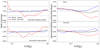 |
Fig. 7. Ratio between the medians of the EM profiles obtained using the X-ray peak or the centroid as centre and using the azimuthal average or median. Left panels: ratio between the medians of the profiles centred on the peak and centroid. The top and bottom panels show the ratio computed using the azimuthal median and azimuthal mean |


5. The profile shape
In this section, we study the shape of the emission measure profiles by checking the impact of the centre definition (as in Sect. 3.3.1) and of the radial profile procedure (as described in Sect. 3.3). Subsequently, we compare the sample median profiles of the relaxed and disturbed sub-samples and compare the CHEX-MATE median profile with the literature and the THE THREE HUNDRED simulations.
5.1. The impact of the profile centre
The impact of the choice of the centre for the profile extraction is crucial for any study that builds on the shape of profiles, such as the determination of the hydrostatic mass profile (see Pratt et al. 2019 for a recent review). The heterogeneity of morphology and the exquisite data quality of the CHEX–MATE sample offer a unique opportunity to assess how the choice of the centre affects the overall shape of the profile.
We show in the top part of the left panel in Fig. 7 the ratio between the medians of the  azimuthal median profiles centred on the peak and those centred on the centroid. The colours of the lines respectively refer to the entire sample and the morphologically relaxed and disturbed sub-samples. The bottom panel shows a similar ratio where the azimuthal mean profiles are considered. From the figure, we noticed that the results obtained using mean or median profiles are similar, with the exception of the outskirts of the disturbed systems, which will be discussed below. On average, the relaxed sub-sample shows little deviation from one at all radial scales, as would be expected since for these systems the X-ray peak likely coincides with the centroid. The variations of the disturbed objects are up to 10% in the centre, where the profiles centred on the X-ray peak are steeper, and about 5% in the [0.15–0.5]
 region, where the centroid profiles have greater emission. These variations are not reflected in the entire CHEX–MATE sample, despite the fact that it includes approximately 87% of the disturbed and morphologically mixed systems. Indeed, in this case, all deviations are within 2%, implying that the choice of referring to the X-ray peak does not influence the shape of the sample median profile.
5.2. Mean versus median
We proceeded by testing the radial profile procedure (Sect. 3.3.1) next, comparing the azimuthal median and the azimuthal mean profiles (Fig. 7) and centring both on either the X-ray peak (top panel) or, for completeness, on the centroid (bottom panel). As expected from the previous results, there are little differences between the two panels. Overall, we noticed that the azimuthal mean profiles are greater than the azimuthal medians, implying that greater density fluctuations are present at all scales and that they play a larger role in the outskirts where a larger number of undetected clumps might be present. The differences between the two profiles are always within 5% for the relaxed systems. The deviations are more important for the disturbed objects, especially when centred on the X-ray peak. This last remark implies that the regions outside  of the CHEX–MATE disturbed objects not only have greater density fluctuations but are also spherically asymmetric in their gas distribution; otherwise, the same mean-median deviations would be detected when considering the centroid as centre. The global effect on the CHEX–MATE sample is that the median profiles are about 7% lower than the mean profiles at
  . We noticed that similar results were obtained by Eckert et al. (2015; see Fig. 6). This test confirmed that our choice of using the azimuthal medians for each cluster profile is more robust for our goal of describing the overall CHEX–MATE radial profiles.
5.3. The median CHEX–MATE profiles and the comparison between relaxed and disturbed systems
In Fig. 2, we show the behaviour of the CHEX–MATE  median as well as the medians of the mass and redshift sub-samples. In the left panel of Fig. 8, we compare the medians of the relaxed and disturbed sub-samples whose individual profiles are shown in Fig. 3. The former is approximately two times greater than the median of the whole sample at
  and is not within the dispersion. The morphologically disturbed clusters are on average within the dispersion, being 70% smaller than the whole sample median at
  . The morphologically relaxed profiles become steeper than the disturbed profiles at
  . A similar behaviour has been observed in several works, such as Arnaud et al. (2010), Pratt et al. (2010), Maughan et al. (2012), and Eckert et al. (2012; see Fig. 4), when comparing cool core systems with non-cool core systems.
 |
Fig. 8. Comparison of the statistical properties of the CHEX–MATE |


Combining these results with those of Fig. 2, we concluded that CHEX–MATE Eq. (5) provides reasonable mass normalisation and captures the evolution of the cluster population well. The large sample dispersion seen in the cluster cores is linked to the variety of morphologies present in the sample. The medians of the relaxed and disturbed sub-samples indeed differ by more than a factor of ten at  . At around
  , we also noticed some different behaviours in our sub-sample: The most massive objects are approximately 25% larger than the least massive ones, and the morphologically disturbed clusters are 50% larger than the relaxed ones (see also Sayers et al. 2023).
5.4. Comparison with other samples
In this section, the statistical properties of the CHEX–MATE profiles are compared to SZ and X-ray selected samples at z ≲ 0.3 with similar mass ranges in order to investigate the impact of different selection effects. The SZ-selected sample is the XMM-Newton Cluster Outskirts Project (X-COP; Eckert et al. 2017) sample that contains 12 SZ-selected clusters in the [0.05-0.1] redshift range and has a total mass range similar to CHEX–MATE but with a greater median mass (∼6 × 10¹⁴ M⊙). The individual  profiles for X-COP were computed using the same procedure as described in this work. The profiles were scaled by applying Eq. (5), with Tavg given by Eq. (1), using the masses presented in Table 1 of Ettori et al. (2019).
We also compare the CHEX–MATE profile properties to the X-ray selected Representative XMM-Newton Cluster Structure Survey (REXCESS; Böhringer et al. 2007) sample, which is composed of 31 X-ray selected clusters in the [0.05–0.3] redshift range, with a mass range spanning the [1–8]×1014 M⊙ and the median mass being 2.7 × 10¹⁴ M⊙. The REXCESS  profiles were obtained from the surface brightness presented in Appendix A of Croston et al. (2008). These profiles were computed using the azimuthal average in each annulus. For this reason, we compare the REXCESS profiles with the mean CHEX–MATE profiles. The REXCESS profiles were scaled using Eq. (5) with Tavg from Pratt et al. (2009).
The median and its dispersion for each of these samples were computed using the procedure described above, and their comparison with CHEX–MATE is shown in the right panel of Fig. 8. Both sample medians present an overall good agreement that is within 10% at  . The X-COP median is 25% more peaked in the central regions at
  with respect to both CHEX–MATE and REXCESS. Nevertheless, the X-COP median is well within the dispersion of the CHEX–MATE sample and variations of such order are expected in the core where the
  values are comprised in the wide range ∼[6, 30]×10−5 cm −6 Mpc.
5.5. Comparison with simulations
The 115 Simx  profiles extracted from random projections for each cluster are shown together with their median value in Fig. 9. The median of the CHEX–MATE sample is also shown. Overall, the CHEX-MATE median is flatter than the medians of Simx in the [0.06–1]
 radial range, and specifically it is ∼50% smaller in the centre and ∼50% larger in the outskirts. Part of the difference in the external regions might be caused by the re-scaling of the observational sample. Indeed, each CHEX–MATE profile has been scaled using the
  derived from
  , which is expected to be biased low by 20%. Factoring in this aspect, a more proper re-scaling should be done with respect to
  . The agreement between the CHEX–MATE data and the simulations increases at
  , with relative variations of about 40% in the [0.2–1]
  radial range. These considerations do not have any repercussion on the central regions, which remain larger in the simulated profiles, confirming the results found in Campitiello et al. (2022) and Darragh-Ford et al. (2023).
 |
Fig. 9. Top panel: Simx |


Providing precise measures of the mass of the observed clusters is one of the goals of the CHEX–MATE Collaboration. For this paper, it is sufficient to prove that THE THREE HUNDRED clusters have a profile in reasonable agreement with the observed sample in order to employ them for the study of the  scatter.
5.6. Measuring the slopes
We measured the slopes of the CHEX–MATE  profiles adopting the technique described in Sect. 3.1 of Ghirardini et al. (2019). Briefly, we considered four radial bins in the [0.2–1] ×
  radial range and with widths equal to
  . We excluded the innermost bin [0.−0.2]
 because of the very high dispersion of the profiles within this region. We measured the slope, α, and normalisation, A, of each profile by performing the fit within each radial bin using the following expression:

where  and σint is the intrinsic scatter. The error on each parameter was estimated via a Monte Carlo procedure, producing 100 realisations of each profile. The left panel of Fig. 10 shows the power law computed using the median of the α and A within each radial bin.
 |
Fig. 10. Results of the fit of the CHEX–MATE |


The fit of the [0.2–0.4] bin revealed that there is a striking difference between the morphologically relaxed and disturbed objects. This result is notable because the considered region is far from the cooling region at
  . The median power law index of the morphologically relaxed object profiles is αrel = 2.57 ± 0.15 and is not consistent with the morphologically disturbed one, which is αdis = 1.37 ± 0.2 at more than the 3σ level. That is, the shape of the most disturbed and relaxed objects differ at least up to
  . However, the fitted power law is within the dispersion of the full sample, whose median index is α = 2.02 ± 0.36. The median values in the
 ![$ [0.4{-}0.6] {R_{500}^{\mathrm{Y}_\mathrm{{SZ}}}} $](/articles/aa/full_html/2023/06/aa46189-23/aa46189-23-eq74.gif) region are αrel = 3 ± 0.22 and αdis = 2.3 ± 0.2 for the morphologically relaxed and disturbed objects, respectively. The indexes are consistent at the 2σ level, implying that the profiles are still affected by the morphology in the centre. The overall scenario changes at
region are αrel = 3 ± 0.22 and αdis = 2.3 ± 0.2 for the morphologically relaxed and disturbed objects, respectively. The indexes are consistent at the 2σ level, implying that the profiles are still affected by the morphology in the centre. The overall scenario changes at  . The power law index of the morphologically relaxed and disturbed objects are consistent with the median obtained from fitting the whole sample. Ettori & Balestra (2009) found that the average slope of a sample of 11 clusters at
  ) and
) and  ) is 3.15 ± 0.46 and 3.86 ± 0.7, respectively. These values are consistent within 1σ with our measurements.
We show in the right panel of Fig. 10 the comparison between the median α computed from the CHEX–MATE sample in each radial bin with the same quantity obtained using REXCESS and X-COP. There is an excellent agreement in all the considered radial bins. Interestingly, there is also a good agreement in the shape between a sample selected in X-ray (REXCESS) and SZ. One could expect to see more differences in the central parts, as X-ray selection should favour peaked clusters.
The comparison with the median α obtained using the Simx profiles is also shown in the right panel of Fig. 10. The Simx median α is systematically greater than the median of the observed sample. As discussed in Sect. 5.5, the bias introduced by using  might play a role when comparing CHEX–MATE to Simx and partly contributes to this systematic difference. However, we stress the fact that the slopes are consistent within 1σ in the four radial bins.
Campitiello et al. (2022) find similar results when comparing the concentration of surface brightness profiles within fixed apertures of simulated and CHEX–MATE clusters. This quantity measures how concentrated the cluster core is with respect to the outer regions (i.e. more concentrated clusters show a steeper profile). The concentration of the simulations is systematically higher by approximately 20 − 30% (see Table 1 of Campitiello et al. 2022).
6. The EM radial profile scatter
6.1. Computation of the scatter
Departures from self-similarity are linked to individual formation history as well as non-gravitational processes such as AGN feedback (outflows, jets, cavities, shocks) and feeding (cooling, multi-phase condensation; e.g., Gaspari et al. 2020). The additional terms used to obtain the  profiles can partly account for these effects. The scatter of these profiles offers the opportunity to quantify such departures, and the CHEX–MATE sample is ideal to achieve this goal since the selection function is simple and well understood.
We computed the intrinsic scatter of the CHEX–MATE radial profiles by applying the following procedure. First, we interpolated each scaled profile on a common grid formed by ten logarithmically spaced radial bins in the ![$ [0.05{-}1.1] {R_{500}^{\mathrm{Y}_\mathrm{{SZ}}}} $](/articles/aa/full_html/2023/06/aa46189-23/aa46189-23-eq80.gif) radial range. We used the model for which the observed distribution of the points, Sobs, in each radial bin is the realisation of an underlying normal distribution, Strue, with log-normal intrinsic scatter, σint:
radial range. We used the model for which the observed distribution of the points, Sobs, in each radial bin is the realisation of an underlying normal distribution, Strue, with log-normal intrinsic scatter, σint:

with μ as the mean value of the distribution. We set broad priors on the parameters we are interested in:


where  is the mean value of the interpolated EM profiles at the radius r. We assumed a Half-Cauchy distribution for the scatter, as this quantity is defined as positive. Since σ(lnX)=σ(X)/X, the intrinsic scatter in linear scale becomes:

and the total scatter, σtot, is the quadratic sum of σlin and the statistical scatter σstat:

The observed data were then assumed to be drawn from a normal realisation of the mean value and total scatter:

We determined the intrinsic scatter σint and its 1σ error by applying the No U-Turn Sampler (NUTS) as implemented in the Python package PyMC3 (Salvatier et al. 2016) and using 1000 output samples.
Our sample contains nine objects for which we were not able to measure the profile above  . Six of these objects are less massive than
  and are classified as “mixed morphology” objects. We investigated the impact of excluding these profiles from the computation of the scatter by comparing the scatter computed within
  using the full sample with the scatter computed excluding the nine objects. We noticed that this exclusion reduces the scatter by a factor of approximately 15% at
  starting from
  . We argue that the reduction of the scatter is linked to the fact that the nine clusters contribute positively to the total scatter being morphologically mixed. For this reason, we corrected for this effect, defining a correction factor, cf, that quantifies the difference in the scatter due to the exclusion of these profiles. We computed the ratio between the scatter including and excluding the nine profiles in the [
 ] radial range, where we extracted the profiles for the whole CHEX–MATE sample. We fitted this ratio via the mpcurvefit routine using a two degree polynomial function of the form cf(r)=ar2 + br + c and obtained the coefficients [a, b, c]=[0.410, −0.117, 0.993]. We multiplied the scatter of the whole sample by cf in the [
![$ 0.06{-}1] {R_{500}^{\mathrm{Y}_\mathrm{{SZ}}}} $](/articles/aa/full_html/2023/06/aa46189-23/aa46189-23-eq94.gif) radial range. From hereon, we refer to this scatter as the “corrected intrinsic scatter”.
radial range. From hereon, we refer to this scatter as the “corrected intrinsic scatter”.
6.2. The CHEX–MATE scatter
The corrected intrinsic scatter of the  profiles is reported in the top-left panel of Fig. 11. The scatter computed using the profiles centred either on the centroid or on the peak gave consistent results.
 |
Fig. 11. Scatter of the |


The intrinsic scatter of the scaled  profiles substantially depends on the scale considered. In the central regions, the large observed scatter of ∼0.8, at
  reflects the complexity of the cluster cores in the presence of non-gravitational phenomena, such as cooling and AGN feedback. On top of that, merging events are known to redistribute gas properties between the core and the outskirts, which flattens the gas density profiles in cluster cores. The scatter reaches a minimum value of ∼0.2 in the [0.3–0.7]
 radial range, where the scatter remains almost constant. This result confirms the behaviour observed in the left panel of Fig. 8, where the dispersion of the profiles shown is minimal in this radial range and the scaled profiles converge to very similar values. The scatter increases at
  from 0.2 to 0.35.
The scatter of the morphologically disturbed and relaxed clusters considered separately are shown in the top-left panel of Fig. 11. The scatter of the morphologically disturbed clusters is higher but consistent at  with the relaxed one. This is expected, as the scatter originates from the combination of non-gravitational processes in the core and merging phenomena. This reinforces the scenario in which the differences between the
  profiles of relaxed and disturbed objects disappear in cluster outskirts, as already shown with the study of the shapes in Sect. 5. The dependency of the scatter on cluster mass was identified by comparing the scatter between high- and low-mass objects, as shown in the top-right panel of Fig. 11. No significant differences could be seen. We investigated the evolution of the scatter by comparing the most massive clusters,
  , in the low- and high-redshift samples. This is shown in the bottom-left panel of the figure, and as for the mass sub-samples, we found no significant differences except in the very inner core at
  , where the local objects indicate larger variation.
6.3. Comparison with other samples
We computed the scatters of the profiles of the REXCESS and X-COP sample following the same procedure we used for the CHEX–MATE sample. These are shown in the bottom-right panel of Fig. 11. The width of the envelope corresponds to 1σ uncertainty. Overall, the CHEX–MATE, REXCESS, and X-COP scatters are consistent at the [0.07–0.6]  radial range. This excellent agreement is due to the fact that the samples are representative of the wide plethora of
  profile shapes in the core of clusters. There is slight disagreement at a larger scale between the samples, with the CHEX–MATE scatter being lower at more than 1σ, which could be do to the re-scaling. This is one important issue that will be investigated in forthcoming papers recurring also to multi-wavelength data.
7. Investigating the origin of the scatter
7.1. Simulation scatters
In this section, we turn our attention to the THE THREE HUNDRED dataset. The cosmological simulations allowed us to break down the sample scatter, or total scatter, into two components: the genuine cluster-to-cluster scatter, which would be the sample scatter measured between the true 3D profiles of the objects, and the projection scatter. The latter measures the differences that various observers across the Universe would detect when looking at the same object from distinct points of view.
In this work, we scaled the CHEX–MATE EM profiles using the results of Pratt et al. (2022) and Ettori et al. (2023), which were derived using empirical ad hoc adaptation of the self-similar scaling predictions. However, the same scaling is less suitable for the simulations, which agree better with the self-similar evolution of Eq. (4) since this expression minimises their scatter. For this reason, all the scatters presented from this point on were derived from EM profiles scaled assuming only self-similar evolution both for THE THREE HUNDRED and CHEX–MATE samples.
7.2. The projection scatter term
The evaluation of this term requires the knowledge of the 3D spatial distribution of the ICM. A perfectly spherical symmetric object would appear identical from all perspectives, and the projection scatter would be equal to zero. On the other hand, an object whose ICM spatial distribution presents a complex morphology will produce a large projection scatter. This can be visualised by looking at the three EM maps obtained for three orthogonal lines of sight for two objects of the THE THREE HUNDRED collaboration in Fig. 12. In detail, the cluster shown in the top rows is roundish and does not show evident traces of merging activity within a radius of R = R500 (white circle). The cluster in the bottom row, however, exhibits a complex morphology due to ongoing merging activities and the presence of sub-structures, which cause it to appear different in the three projections.
 |
Fig. 12. EM maps of two of the simulated clusters used in this work projected along the lines of sight X, Y, and Z. The top row shows a cluster whose morphology appears roundish in the three projections considered. On the bottom we show, on the contrary, a cluster whose morphology is particularly complex and appears different in each of the three projections. We refer to the cluster in the top row as regular and the latter as irregular. The white circle indicates R500. |
This complexity is reflected in the projection scatters shown in Fig. 13, which was computed considering the 40 lines of projection for the two objects and not only the three shown with the images. The scatters are similar within R < 0.2R500. At R > 0.4R500, the irregular cluster scatter diverges, while the one of the regular object remains almost constant. In particular, in the case of the irregular object, ∼0.4R500 corresponds to the position of the big sub-structure visible in the bottom row of the left panel of Fig. 12. Interestingly, the Simx projection scatter increases rapidly at R ∼ 0.8R500 also for the regular cluster, while the Sim one remains mostly constant. This difference in the behaviour is due to the deliberate 7% over- and underestimated background correction explained in Sect. 4.2. The over-and underestimation of the background yields profiles that are steeper or flatter than the correct profiles, respectively, and hence they increase the scatter between the profiles. This effect is particularly important at R ∼ R500 because the cluster signal reaches the background level.
 |
Fig. 13. Projection scatter of the regular and irregular clusters in Fig. 12. The scatters are shown with black and red solid lines, respectively. The black and red envelops represent the dispersion. The black and red dotted lines refer to the projection scatter computed using the Simx profiles. |
We calculated the projection scatter between the 40 projections for each of the 115 objects from THE THREE HUNDRED sample, and these profiles are shown in Fig. 14. On average, the scatter starts from a value of 0.15 at R ∼ 0.1R500 and then reaches the value of 0.3 at R500, with a rapid increase from 0.2 to 0.3 at R ∼ 0.9R500. This rapid increase is due to the complex spatial ICM distribution at large radii. There are approximately five outliers that exhibit a larger scatter from the envelope and a complex behaviour. These clusters are characterised by the presence of sub-structures that happen to be behind or in front of the main halo of the cluster along some lines of projection. For this reason, the sub-structure emission is not visible as it blends with the emission from the core of the cluster. On the contrary, if the sub-halo is on a random position as respect to the main halo it will appear as a sub-structure in different position depending on the projection. In this case, the cluster morphology is complex. For these reasons, the resulting profile for these clusters can show remarkable differences depending on the line of sight.
 |
Fig. 14. Comparison between the total and projection scatters of the Simx profiles. The scatters are shown with solid green and magenta lines, respectively. |
7.3. The total scatter term
The total scatter term measures the differences between the cluster EM profiles within a sample. We recall that each of our simulated objects is seen along 40 lines of sight. With this possibility in hand, we created 40 realisations of the same sample of 115 objects and computed the scatter for each realisation. The 40 total scatters of the Simx profiles are shown in Fig. 14.
The average high value of 0.9 at R < 0.3R500 of the total scatter captures the wide range of the profile shapes within the inner core. The scatter reaches its minimum value of ∼0.4 at  and then rapidly increases afterwards, due to the presence of sub-structures in the outskirts and the phenomena related to merging activities as well as the background subtraction discussed in Sect. 7.2.
7.4. Comparison between total and projection
Direct comparison of the projection and total scatter terms in the simulated sample allowed us to investigate the origin of the scatter as predicted by numerical models. The two scatters are shown in Fig. 14. The total scatter is almost eight times greater than the projection at R ∼ 0.1R500 and rapidly decreases to be only two times greater at R ∼ 0.3R500, as shown in Fig. 14. This indicates that differences between clusters dominate with respect to the variations from the projection along different lines of sight at such scale.
The total scatter is only 20% greater than the projection term in the ![$ [0.4{-}0.8]{R_{500}^{\mathrm{Y}_\mathrm{{SZ}}}} $](/articles/aa/full_html/2023/06/aa46189-23/aa46189-23-eq111.gif) radial range. This scale is where the cluster differences are smaller. At
radial range. This scale is where the cluster differences are smaller. At  , both scatters increase, implying that merging phenomena and sub-structures are impacting the distribution of the gas. Furthermore, we argue that the deliberate background over- and under-subtraction discussed in Sect. 7.2 contributes to increasing both scatter terms by enlarging the distribution of the profiles where the signal of the cluster reaches the background level. The total scatters obtained using the Sim are similar to the ones obtained using Simx up to 0.9R500 but remain below ∼0.45 at R500.
7.5. Simulation versus observations
We can break down the contributions to the scatter in the CHEX–MATE sample by using the numerical simulation scatter terms as a test bed. The Simx total and projection scatter medians and their dispersion are shown in Fig. 15. The CHEX–MATE scatter dispersion is also shown in the same figure. We recall that it is computed using the EM profiles scaled according to the self-similar model using Eq. (2) and is greater than the one shown in Fig. 11 due to the residual dependency on mass and redshift discussed in Sect. 3.3.2 in the [0.2 − 0.8] radial range. However, the scatters reach the value of approximately 0.4 at  , indicating that the differences between the profiles are dominated by clumpy patches in the ICM distribution due to sub-halos and filamentary structures.
 |
Fig. 15. Comparison between the scatter of the CHEX–MATE sample and the total and projection terms of the simulations. The CHEX–MATE scatter is shown using dashed black lines. The medians of the total and projection terms are represented with green and magenta solid lines, respectively. Their 68% dispersions are represented using envelopes coloured accordingly. |
The CHEX–MATE and Simx total scatters are in excellent agreement at  and marginally consistent within 2σ in the [0.1–0.3] radial range. Generally speaking, they exhibit the same behaviour, rapidly declining from the maximum value of the scatter of 1.2–0.4. The projection scatter on the other hand is at a minimum value of 0.1 and is almost constant up to
  . This result implies that the observed scatter between the EMS profiles within
  is dominated by genuine differences between objects and not by the projection along one line of sight, as explained in Sect. 7.4. In other words, we are not limited by the projection on the plane of the sky when studying galaxy cluster population properties at such scales.
The total and CHEX–MATE scatters reach the minimum value, approximately 0.4, in the [![$ 0.3{-}0.5] {R_{500}^{\mathrm{Y}_\mathrm{{SZ}}}} $](/articles/aa/full_html/2023/06/aa46189-23/aa46189-23-eq117.gif) radial range and remain almost constant within these radii. This minimum value quantifies the narrow distribution of the profiles shown in Figs. 3 and 6. Furthermore, the slopes between morphologically relaxed and disturbed objects become consistent at such radii, as shown in the right panel of Fig. 10. This suggests that the differences between EM profiles are minimum at such intermediate scales despite their morphological statuses, mass or redshift. As for the inner regions, the projection term increases mildly in these regions and provides a small contribution.
radial range and remain almost constant within these radii. This minimum value quantifies the narrow distribution of the profiles shown in Figs. 3 and 6. Furthermore, the slopes between morphologically relaxed and disturbed objects become consistent at such radii, as shown in the right panel of Fig. 10. This suggests that the differences between EM profiles are minimum at such intermediate scales despite their morphological statuses, mass or redshift. As for the inner regions, the projection term increases mildly in these regions and provides a small contribution.
The THE THREE HUNDRED scatters rapidly increase at  , with the total scatter reaching the value of approximately 0.7 at R500. The projection scatter reaches the CHEX–MATE scatter at
  . We argue that this effect is due to a combination of not masking the sub-structures when extracting the Simx profiles and the deliberate wrong background subtraction discussed in Sect. 7.2. Indeed, the use of median profiles reduces this effect, and we discuss this effect in detail in Appendix A, where we show that the use of azimuthal median profiles is efficient for removing part of these spatial features. The fact that the scatter terms increase in a similar manner despite the use of median profiles reinforces that this behaviour is likely related to analysis techniques rather than genuine differences within the profiles and projection effects.
8. Discussion and conclusion
We have studied the properties of the SX and EM radial profiles of the CHEX–MATE sample, which comprises 116 SZ selected clusters observed for the first time with deep and homogeneous XMM-Newton observations. Our main findings are as follows:
-
The choice of making the centre between the peak and the centroid for extraction of the SX profiles yields consistent results in the [0.05–1]
 radial range. Significant differences can be seen within
  .
. -
The use of azimuthal average and median techniques to extract the profiles impacts the overall profile normalisation by a factor of 5% on average. The shape is mostly affected at
 with azimuthal averaged profiles being flatter at this scale.
 -
The EM profiles exhibit a dependency on the mass and a mild dependency on redshift, which is not accounted for by the computed scaling according to the self-similar scenario, as found also by Pratt et al. (2022) and Ettori et al. (2023).
-
Morphologically disturbed and relaxed cluster
 profiles have different normalisations and shapes within
  . The differences at larger radii are on average within 10% and are consistent within the dispersion of the full sample.
 -
The shape and normalisation of the
 profiles present a continuum distribution within the [0.2–0.4]
 radial range. The extreme cases of morphologically relaxed and disturbed objects are characterised by power law indexes, α = 2.51 ± 0.13 and α = 1.38 ± 0.2, respectively, that are not consistent at the 3σ level. The picture changes at
  , where the slopes of these extremes becomes marginally consistent at 1σ in the
 ![$ [0.4{-}0.6]{R_{500}^{\mathrm{Y}_\mathrm{{SZ}}}} $](/articles/aa/full_html/2023/06/aa46189-23/aa46189-23-eq128.gif) radial bin. The slopes in the last bin are in excellent agreement.
radial bin. The slopes in the last bin are in excellent agreement. -
The scatter of the CHEX–MATE sample depends on the scale. The scatter maximum is ∼1.1 within
 , reflecting the wide range of profile shapes within the cluster cores that range from the flat emission of disturbed objects to the peaked emission of the relaxed clusters. The scatter decreases towards its minimum value, 0.2, at
  and increases rapidly to 0.4 at
  . This result is coherent with the overall picture of a characteristic scale,
  , at which the differences between profiles in terms of shape and normalisation are minimum. The increase of the scatter at
  is expected, as this is the scale at which merging related phenomena and patchy distribution of the ICM become important.
 -
The scatters of the morphologically relaxed cluster and the disturbed cluster are different within
 , the former being smaller. Above this radius, they are in excellent agreement between themselves and with the entire sample as well, implying that the properties of EM profiles in the outer parts are not affected by the properties in the core. There are no differences in the scatter of the sub-samples formed by high- and low-mass objects, and we found no evolution of the scatter for high-mass objects.
The overall emerging picture is that there is a characteristic scale,  , where the differences between profiles in terms of shape and normalisation are minimum. The exceptional data quality has allowed us to provide to the scientific community the scatter of SX and
  radial profiles of a representative cluster sample with an unprecedented precision of approximately 5%.
The results from observations were compared to a sample drawn from the numerical simulation suite THE THREE HUNDRED formed by 115 galaxy clusters selected to reflect the CHEX–MATE mass and redshift distribution. For each cluster, we computed the EM along 40 randomly distributed lines of sight, which allowed for the investigation of projection effects for the first time. Our main findings can be summarised as follows:
-
The properties derived using the Sim or the Simx profiles are similar within R500, confirming the statistical quality of the mock X-ray images, which were calibrated to match the CHEX–MATE average statistical quality.
-
The simulation
 profiles appear systematically steeper than those from observations. The hydrostatic bias might play a key role in explaining this difference. The scaling of the CHEX–MATE profiles by
  , assuming a 20% bias, alleviates these differences, and the ratio between the CHEX–MATE and simulation medians becomes closer to one, with the exception of the centre where simulations typically have a greater gas density.
 -
The total scatter of the simulation sample follows the same behaviour as that of the observations up to
 and then increases more rapidly to an average value of approximately 0.7, whereas the observation reaches the value of 0.4 at
  . The comparison with the projection scatter at such scales hints at a contribution from projection effects on the order of 0.3.
 -
The projection scatter allowed us to study the spherical symmetry of clusters. This term slightly increases from approximately 0.1 at
 up to approximately 0.3 at
  , exhibiting a rapid gradient at
  . This term is smaller than the total in the entire
 ![$ [0.1{-}0.9]{R_{500}^{\mathrm{Y}_\mathrm{{SZ}}}} $](/articles/aa/full_html/2023/06/aa46189-23/aa46189-23-eq144.gif) radial range considered, and its dispersion is on the order of 10%. This implies that the difference we observe between objects is due to a genuine difference in the gas spatial distribution.
radial range considered, and its dispersion is on the order of 10%. This implies that the difference we observe between objects is due to a genuine difference in the gas spatial distribution. -
The background subtraction process becomes crucial at R500 for determining of the profile shape at
 . The deliberate over- or underestimation significantly contributes to increasing both the total and projection scatter at such large scales. Furthermore, the rapid increase of both scatters can be also explained by the fact that sub-structures are not masked in simulated images.
The large statistics offered by the simulation dataset allowed us for the first time to investigate the origin of the scatter and break down the components, namely the projection and total terms, and study them as a function of  . The overall picture emerging is that there are three regimes amongst the scatter:
-
[0.1 − 0.4]: The differences between profiles are genuinely due to a different distribution of the gas and also influenced by feedback processes and their implementation (see, e.g., Gaspari et al. 2014), which translates into a plethora of profile shapes and normalisations.
-
[0.4 − 0.6]: In this range, the scatter is sensitive to the scaling applied, suggesting that this is the scale where clusters are closer to being within the self-similar scenario.
-
[0.6 − 1]: The CHEX–MATE scatter and the total scatter increase at such scales and are greater by a factor of approximately two than the projection, showing that profile differences are genuine and not due to projection effects. The emission of sub-structures and filamentary structures and the correct determination of the background play a crucial role in determining the shape of the profiles at such scales.
We were able to investigate the origin of the scatter by combining the statistical power of the CHEX–MATE sample not only because of the great number of objects observed with sufficient exposure time to measure surface brightness profiles above  but also because of the sample’s homogeneity and the uniqueness of the simulation sample. The latter allowed us to discriminate the scatter due to genuine differences between profiles and those related to projection. The CHEX–MATE sample allowed us to measure the scatter up to
  with the sufficient precision to clearly discriminate the contribution from the projection term at all scales.
Acknowledgments
The authors thank the referee for his/her comments. We acknowledge financial contribution from the contracts ASI-INAF Athena 2019-27-HH.0, “Attività di Studio per la comunità scientifica di Astrofisica delle Alte Energie e Fisica Astroparticellare” (Accordo Attuativo ASI-INAF No. 2017-14-H.0), and from the European Union’s Horizon 2020 Programme under the AHEAD2020 project (grant agreement No. 871158). This research was supported by the International Space Science Institute (ISSI) in Bern, through ISSI International Team project #565 (Multi-Wavelength Studies of the Culmination of Structure Formation in the Universe). The results reported in this article are based on data obtained with XMM-Newton, an ESA science mission with instruments and contributions directly funded by ESA Member States and NASA. GWP acknowledges financial support from CNES, the French space agency.
References
- Allen, S. W., Evrard, A. E., & Mantz, A. B. 2011, ARA&A, 49, 409 [Google Scholar]
- Anders, E., & Grevesse, N. 1989, Geochim. Cosmochim. Acta, 53, 197 [Google Scholar]
- Andrade-Santos, F., Jones, C., Forman, W. R., et al. 2017, ApJ, 843, 76 [Google Scholar]
- Ansarifard, S., Rasia, E., Biffi, V., et al. 2020, A&A, 634, A113 [NASA ADS] [CrossRef] [EDP Sciences] [Google Scholar]
- Arnaud, M., Neumann, D. M., Aghanim, N., et al. 2001, A&A, 365, L80 [NASA ADS] [CrossRef] [EDP Sciences] [Google Scholar]
- Arnaud, M., Aghanim, N., & Neumann, D. M. 2002, A&A, 389, 1 [NASA ADS] [CrossRef] [EDP Sciences] [Google Scholar]
- Arnaud, M., Pratt, G. W., Piffaretti, R., et al. 2010, A&A, 517, A92 [CrossRef] [EDP Sciences] [Google Scholar]
- Böhringer, H., Schuecker, P., Pratt, G. W., et al. 2007, A&A, 469, 363 [NASA ADS] [CrossRef] [EDP Sciences] [Google Scholar]
- Borgani, S., & Kravtsov, A. 2011, Adv. Sci. Lett., 4, 204 [Google Scholar]
- Campitiello, G., Giacintucci, S., Lovisari, L., et al. 2022, ApJ, 925, 91 [NASA ADS] [CrossRef] [Google Scholar]
- Cappellari, M., & Copin, Y. 2003, MNRAS, 342, 345 [Google Scholar]
- CHEX-MATE Collaboration (Arnaud, M., et al.) 2021, A&A, 650, A104 [NASA ADS] [CrossRef] [EDP Sciences] [Google Scholar]
- Croston, J. H., Pratt, G. W., Böhringer, H., et al. 2008, A&A, 487, 431 [NASA ADS] [CrossRef] [EDP Sciences] [Google Scholar]
- Cui, W., Power, C., Biffi, V., et al. 2016, MNRAS, 456, 2566 [NASA ADS] [CrossRef] [Google Scholar]
- Cui, W., Knebe, A., Yepes, G., et al. 2018, MNRAS, 480, 2898 [Google Scholar]
- Darragh-Ford, E., Mantz, A. B., Rasia, E., et al. 2023, MNRAS, 521, 790 [NASA ADS] [CrossRef] [Google Scholar]
- Diehl, S., & Statler, T. S. 2006, MNRAS, 368, 497 [NASA ADS] [CrossRef] [Google Scholar]
- Dolag, K., Hansen, F. K., Roncarelli, M., & Moscardini, L. 2005, MNRAS, 363, 29 [Google Scholar]
- Eckert, D., Vazza, F., Ettori, S., et al. 2012, A&A, 541, A57 [NASA ADS] [CrossRef] [EDP Sciences] [Google Scholar]
- Eckert, D., Roncarelli, M., Ettori, S., et al. 2015, MNRAS, 447, 2198 [Google Scholar]
- Eckert, D., Ettori, S., Pointecouteau, E., et al. 2017, Astron. Nachr., 338, 293 [Google Scholar]
- Ettori, S., & Balestra, I. 2009, A&A, 496, 343 [NASA ADS] [CrossRef] [EDP Sciences] [Google Scholar]
- Ettori, S., Gastaldello, F., Leccardi, A., et al. 2010, A&A, 524, A68 [NASA ADS] [CrossRef] [EDP Sciences] [Google Scholar]
- Ettori, S., Donnarumma, A., Pointecouteau, E., et al. 2013, Space Sci. Rev., 177, 119 [Google Scholar]
- Ettori, S., Ghirardini, V., Eckert, D., et al. 2019, A&A, 621, A39 [NASA ADS] [CrossRef] [EDP Sciences] [Google Scholar]
- Ettori, S., Lovisari, L., & Eckert, D. 2023, A&A, 669, A133 [NASA ADS] [CrossRef] [EDP Sciences] [Google Scholar]
- Gaspari, M., Brighenti, F., Temi, P., & Ettori, S. 2014, ApJ, 783, L10 [NASA ADS] [CrossRef] [Google Scholar]
- Gaspari, M., Tombesi, F., & Cappi, M. 2020, Nat. Astron., 4, 10 [Google Scholar]
- Ghirardini, V., Eckert, D., Ettori, S., et al. 2019, A&A, 621, A41 [NASA ADS] [CrossRef] [EDP Sciences] [Google Scholar]
- Ghizzardi, S. 2001, XMM-SOC-CAL-TN-0022 [Google Scholar]
- Ghizzardi, S., Molendi, S., van der Burg, R., et al. 2021, A&A, 646, A92 [NASA ADS] [CrossRef] [EDP Sciences] [Google Scholar]
- Giacconi, R., Rosati, P., Tozzi, P., et al. 2001, ApJ, 551, 624 [Google Scholar]
- Kelly, B. C. 2007, ApJ, 665, 1489 [Google Scholar]
- Klypin, A., Yepes, G., Gottlöber, S., Prada, F., & Heß, S. 2016, MNRAS, 457, 4340 [Google Scholar]
- Kuntz, K. D., & Snowden, S. L. 2000, ApJ, 543, 195 [Google Scholar]
- Le Brun, A. M. C., Arnaud, M., Pratt, G. W., & Teyssier, R. 2018, MNRAS, 473, L69 [Google Scholar]
- Lovisari, L., & Ettori, S. 2021, Universe, 7, 254 [NASA ADS] [CrossRef] [Google Scholar]
- Maughan, B. J., Giles, P. A., Randall, S. W., Jones, C., & Forman, W. R. 2012, MNRAS, 421, 1583 [Google Scholar]
- Neumann, D. M. 2005, A&A, 439, 465 [NASA ADS] [CrossRef] [EDP Sciences] [Google Scholar]
- Neumann, D. M., & Arnaud, M. 1999, A&A, 348, 711 [NASA ADS] [Google Scholar]
- Neumann, D. M., & Arnaud, M. 2001, A&A, 373, L33 [NASA ADS] [CrossRef] [EDP Sciences] [Google Scholar]
- Planck Collaboration XIII. 2016, A&A, 594, A13 [NASA ADS] [CrossRef] [EDP Sciences] [Google Scholar]
- Planck Collaboration XX. 2014, A&A, 571, A20 [NASA ADS] [CrossRef] [EDP Sciences] [Google Scholar]
- Planck Collaboration XXVII. 2016, A&A, 594, A27 [NASA ADS] [CrossRef] [EDP Sciences] [Google Scholar]
- Planelles, S., Fabjan, D., Borgani, S., et al. 2017, MNRAS, 467, 3827 [Google Scholar]
- Pratt, G. W., Croston, J. H., Arnaud, M., & Böhringer, H. 2009, A&A, 498, 361 [NASA ADS] [CrossRef] [EDP Sciences] [Google Scholar]
- Pratt, G. W., Arnaud, M., Piffaretti, R., et al. 2010, A&A, 511, A85 [NASA ADS] [CrossRef] [EDP Sciences] [Google Scholar]
- Pratt, G. W., Arnaud, M., Biviano, A., et al. 2019, Space Sci. Rev., 215, 25 [Google Scholar]
- Pratt, G. W., Arnaud, M., Maughan, B. J., & Melin, J. B. 2022, A&A, 665, A24 [NASA ADS] [CrossRef] [EDP Sciences] [Google Scholar]
- Rasia, E., Meneghetti, M., & Ettori, S. 2013, Astron. Rev., 8, 40 [Google Scholar]
- Rasia, E., Borgani, S., Murante, G., et al. 2015, ApJ, 813, L17 [Google Scholar]
- Roncarelli, M., Ettori, S., Dolag, K., et al. 2006, MNRAS, 373, 1339 [Google Scholar]
- Roncarelli, M., Ettori, S., Borgani, S., et al. 2013, MNRAS, 432, 3030 [NASA ADS] [CrossRef] [Google Scholar]
- Rossetti, M., Gastaldello, F., Eckert, D., et al. 2017, MNRAS, 468, 1917 [Google Scholar]
- Sabol, E. J., & Snowden, S. L. 2019, Astrophysics Source Code Library [record ascl:1904.001] [Google Scholar]
- Salvatier, J., Wiecki, T., & Fonnesbeck, C. 2016, PeerJ-CS, e55 [Google Scholar]
- Sayers, J., Mantz, A. B., Rasia, E., et al. 2023, ApJ, 944, 221 [NASA ADS] [CrossRef] [Google Scholar]
- Schellenberger, G., Giacintucci, S., Lovisari, L., et al. 2022, ApJ, 925, 91 [NASA ADS] [CrossRef] [Google Scholar]
- Sereno, M., Ettori, S., & Baldi, A. 2012, MNRAS, 419, 2646 [NASA ADS] [CrossRef] [Google Scholar]
- Sereno, M., Ettori, S., Meneghetti, M., et al. 2017, MNRAS, 467, 3801 [NASA ADS] [CrossRef] [Google Scholar]
- Sereno, M., Umetsu, K., Ettori, S., et al. 2018, ApJ, 860, L4 [NASA ADS] [CrossRef] [Google Scholar]
- Snowden, S. L., Mushotzky, R. F., Kuntz, K. D., & Davis, D. S. 2008, A&A, 478, 615 [NASA ADS] [CrossRef] [EDP Sciences] [Google Scholar]
- Strüder, L., Briel, U., Dennerl, K., et al. 2001, A&A, 365, L18 [Google Scholar]
- Sunyaev, R. A., & Zeldovich, I. B. 1980, ARA&A, 18, 537 [Google Scholar]
- Turner, M. J. L., Abbey, A., Arnaud, M., et al. 2001, A&A, 365, L27 [CrossRef] [EDP Sciences] [Google Scholar]
- Vikhlinin, A., Forman, W., & Jones, C. 1999, ApJ, 525, 47 [NASA ADS] [CrossRef] [Google Scholar]
- Voit, G. M. 2005, Rev. Mod. Phys., 77, 207 [Google Scholar]
- Voit, G. M., Kay, S. T., & Bryan, G. L. 2005, MNRAS, 364, 909 [NASA ADS] [CrossRef] [Google Scholar]
- Zhuravleva, I., Churazov, E., Kravtsov, A., et al. 2013, MNRAS, 428, 3274 [NASA ADS] [CrossRef] [Google Scholar]
Appendix A: The impact of sub-structures in simulations
The presence of sub-structures within the region of extraction of the radial profiles modifies the shape of the surface brightness and emission measure profiles. This translates into an increase of the scatter between them. In this work, we are interested in the distribution of the gas within the cluster halo filtering the contribution of sub-structures whose emission is detectable within or near  . This filtering is achieved by masking the sub-structures in observations. The same procedure is difficult to apply to simulations.
Generally speaking, automatic detection algorithms in X-ray analyses are calibrated to detect point source emission only, as the detection of extended sources would cause the algorithm to also detect the cluster emission itself. For this reason, the identification of extended emission associated to sub-structures is done via eye inspection, but this approach cannot be taken with large datasets comprised of thousands of maps, such as the one we used in this work. The fact that we do not mask sub-structures in the simulated maps constitutes one of the main differences between the X-ray analysis and THE THREE HUNDRED analysis. However, we could qualitatively investigate the impact of sub-structures on the scatter by comparing the results obtained following the procedures of Section 7 that used the azimuthal average and median profiles shown in Fig. A.1.
 |
Fig. A.1. Comparison between the total scatters computed using the azimuthal mean and median profiles. Top: Medians of the total from THE THREE HUNDRED scatters computed using the azimuthal mean and median EM profiles. These are shown with green and grey lines, respectively. The 68% dispersion is shown with the coloured envelopes. Bottom: Ratio between the median of the total scatters computed using the azimuthal averaged profiles over the median computed using the azimuthal median profiles. The dashed-dotted lines indicate the identity line and the ±20% levels. |
The bottom panel shows that the scatters are nearly identical, within 0.2R500, and are on average around the 20% level in the [0.2-0.6]R500 radial range. The scatter of the mean profiles increases rapidly above that radius. The same behaviour is observed for the scatter of the median even if the increase is less rapid, as shown by the ratio in the bottom panel at R> 0.6R500.
The azimuthal median in a given annulus does not completely remove the emission from the extended sub-structure, which can only be achieved by masking it. However, we argue that the scales at which the sub-structures become important, R> 0.6R500, correspond to annuli whose size is typically larger than the size of a sub-halo. For this reason, the azimuthal median is marginally affected.
Indeed, sub-structure masking is a key difference between observations and simulations, and it does affect the computation of the total scatter. However, we suggest that using the median profiles is an effective way to reduce the impact of sub-structures at the scales at which they are important. For this reason, the rapid increase of the total scatter at ∼R500 is more likely to be due to a genuine difference between the profiles and to the background subtraction effect discussed in Section 7.2.
Appendix B: ROSAT-XMM- Newton background relation
The determination of the sky background level was performed in a region free from cluster emission. In this work, we used the annular region between  and 13.5 arcminutes to measure the photon count rate associated with the sky background. We considered that we had sufficient statistics for the background estimation if the width of this region is at least 1.5 arcmin (i.e.
  arcmin). The
  of nearby clusters at z ≲0.2 are generally larger than 12 arcmin, and it was not possible to define a sky background region unless offset observations were available. For this reason, we predicted the sky background for these objects using the ROSAT All-Sky Survey diffuse background maps obtained with the Position Sensitive Proportional Counters (PSPC).
We determined the ROSAT photon count rate, ROSATcr, for each CHEX–MATE object in the R5 band, [0.73 − 1.56] keV, within an annular region centred on the X-ray peak and with the minimum and maximum radius being  and 1.5 degrees, respectively, using the sxrbg tool (Sabol & Snowden 2019). We then calibrated the relation between the ROSATcr and the XMM-Newton background sky count rate, XMMcr, for clusters whose
  was less than 12 by performing a linear regression using the linmix package (Kelly 2007):

The results of the linear regression for the mean and median profiles are shown in the left and right panels of Fig. B.1, respectively. The values of the linear minimisation y = α + β * x and the intrinsic scatter ϵ are reported in Table B.1. We used these relations to estimate the XMM-Newton sky background for the objects where  is greater than 12 arcmin in the CHEX–MATE sample.
 |
Fig. B.1. Calibration of the sky background count rate between XMM-Newton and ROSAT-PSPC. Left panel: Relation between the sky background count rate as measured using the XMM-Newton mean SX profiles and ROSAT-PSPC in the R5, [0.56-1.21] keV, energy band. The black points represent the clusters for which |


Results of the linear minimisation of the ROSAT-R5 vs XMM-Newton sky background count rate shown in Equation B.1.
Appendix C: Power law fit
We report in Table C.1 the results of the fit of the median  profiles centred on the X-ray peak profiles using the power law shown in Eq. 6 and described in Sect. 5. The fit was performed using the mean value of each bin as the pivot for the radius, that is, 0.3, 0.5, 0.7, and 0.9 for the [0.2-0.4], [0.4-0.6], [0.6-0.8], and [0.8-1]
  radial bins, respectively.
Results of the power law fit shown in Equation 6.
Appendix D: Surface brightness profiles
We show in D.1 the surface brightness profiles of the CHEX–MATE sample that we extracted as described in Section 3.3.1. Thedotted line shown in the top-left panel indicates  and highlights the data quality of the sample as most of the profiles extend beyond that radius.
 |
Fig. D.1. Surface brightness radial profiles of the CHEX–MATE sample. Left column: Azimuthal averaged surface brightness profiles of the CHEX–MATE sample centred on the X-peak and the centroid in the top and bottom panels, respectively. Blue and red solid lines represent morphologically relaxed and disturbed clusters, respectively. The black solid vertical line identifies |

Observational, morphological, and global properties of the CHEX–MATE sample.
All Tables
Results of the linear minimisation of the ROSAT-R5 vs XMM-Newton sky background count rate shown in Equation B.1.
All Figures
|
Fig. 1. Distribution of the clusters published in the PSZ2 Planck catalogue (Planck Collaboration XXVII 2016) in the mass-redshift plane. The masses in the Planck catalogue were derived iteratively from the M500–YSZ relation calibrated using hydrostatic masses from XMM-Newton; they were not corrected for the hydrostatic equilibrium bias. The magenta and green points represent the Tier 1 and Tier 2 clusters of the CHEX–MATE sample, respectively (CHEX-MATE Collaboration 2021). The triangles and squares identify the morphologically relaxed and disturbed clusters, respectively, which were identified according to the classification scheme in Campitiello et al. (2022). The two red crosses identify the clusters excluded from the analysis of this work. |
| In the text | |
|
Fig. 2. Comparison of the statistical properties of the CHEX–MATE EM profiles divided in redshift and mass selected sub-samples. Top-left panel: median of the EMS profiles centred on the X-ray peak scaled for self-similar evolution using Eq. (4). The dispersion is shown with the black solid line and the grey envelope. The magenta and green solid lines represent the median of the low-mass, |
| In the text | |
|
Fig. 3. Scaled emission measure median profiles centred on the X-ray peak. The blue and red solid lines indicate morphologically relaxed and disturbed clusters, respectively. The profiles extracted from clusters with mixed morphology are shown with black solid lines. The selection criteria was based on the classification made by Campitiello et al. (2022) in their Sect. 8.2. The grey-shaded envelope represents the dispersion at the 68% level. |
| In the text | |
|
Fig. 4. Mass distribution of the CHEX–MATE and THE THREE HUNDRED samples. These are shown with black empty and green polygons, respectively. The gap between |
| In the text | |
|
Fig. 5. Example of the creation of the X-ray mock images. Left panel: EM map of a simulated cluster of our sample. The white circle encompasses R500. Right panel: Mock X-ray background-subtracted image in the [0.5–2] keV band of the same object shown in the left panel after we applied the procedures simulating typical X-ray observation effects. These are described in detail in Sect. 4.1. |
| In the text | |
|
Fig. 6. Comparison between the Sim and Simx profiles. Top panel: comparison between the medians of the Sim and Simx |
| In the text | |
|
Fig. 7. Ratio between the medians of the EM profiles obtained using the X-ray peak or the centroid as centre and using the azimuthal average or median. Left panels: ratio between the medians of the profiles centred on the peak and centroid. The top and bottom panels show the ratio computed using the azimuthal median and azimuthal mean |
| In the text | |
|
Fig. 8. Comparison of the statistical properties of the CHEX–MATE |
| In the text | |
|
Fig. 9. Top panel: Simx |
| In the text | |
|
Fig. 10. Results of the fit of the CHEX–MATE |
| In the text | |
|
Fig. 11. Scatter of the |
| In the text | |
|
Fig. 12. EM maps of two of the simulated clusters used in this work projected along the lines of sight X, Y, and Z. The top row shows a cluster whose morphology appears roundish in the three projections considered. On the bottom we show, on the contrary, a cluster whose morphology is particularly complex and appears different in each of the three projections. We refer to the cluster in the top row as regular and the latter as irregular. The white circle indicates R500. |
| In the text | |
|
Fig. 13. Projection scatter of the regular and irregular clusters in Fig. 12. The scatters are shown with black and red solid lines, respectively. The black and red envelops represent the dispersion. The black and red dotted lines refer to the projection scatter computed using the Simx profiles. |
| In the text | |
|
Fig. 14. Comparison between the total and projection scatters of the Simx profiles. The scatters are shown with solid green and magenta lines, respectively. |
| In the text | |
|
Fig. 15. Comparison between the scatter of the CHEX–MATE sample and the total and projection terms of the simulations. The CHEX–MATE scatter is shown using dashed black lines. The medians of the total and projection terms are represented with green and magenta solid lines, respectively. Their 68% dispersions are represented using envelopes coloured accordingly. |
| In the text | |
|
Fig. A.1. Comparison between the total scatters computed using the azimuthal mean and median profiles. Top: Medians of the total from THE THREE HUNDRED scatters computed using the azimuthal mean and median EM profiles. These are shown with green and grey lines, respectively. The 68% dispersion is shown with the coloured envelopes. Bottom: Ratio between the median of the total scatters computed using the azimuthal averaged profiles over the median computed using the azimuthal median profiles. The dashed-dotted lines indicate the identity line and the ±20% levels. |
| In the text | |
|
Fig. B.1. Calibration of the sky background count rate between XMM-Newton and ROSAT-PSPC. Left panel: Relation between the sky background count rate as measured using the XMM-Newton mean SX profiles and ROSAT-PSPC in the R5, [0.56-1.21] keV, energy band. The black points represent the clusters for which |
| In the text | |
|
Fig. D.1. Surface brightness radial profiles of the CHEX–MATE sample. Left column: Azimuthal averaged surface brightness profiles of the CHEX–MATE sample centred on the X-peak and the centroid in the top and bottom panels, respectively. Blue and red solid lines represent morphologically relaxed and disturbed clusters, respectively. The black solid vertical line identifies |
| In the text | |
Current usage metrics show cumulative count of Article Views (full-text article views including HTML views, PDF and ePub downloads, according to the available data) and Abstracts Views on Vision4Press platform.
Data correspond to usage on the plateform after 2015. The current usage metrics is available 48-96 hours after online publication and is updated daily on week days.
Initial download of the metrics may take a while.