| Issue |
A&A
Volume 652, August 2021
|
|
|---|---|---|
| Article Number | A22 | |
| Number of page(s) | 19 | |
| Section | Interstellar and circumstellar matter | |
| DOI | https://doi.org/10.1051/0004-6361/202140514 | |
| Published online | 03 August 2021 | |
Toward a 3D kinetic tomography of Taurus clouds
I. Linking neutral potassium and dust★
1
LATMOS, Université Versailles-Saint-Quentin,
11 Bd D’Alembert,
Guyancourt,
France
e-mail: This email address is being protected from spambots. You need JavaScript enabled to view it.
2
Space Research Institute (IKI), Russian Academy of Science,
Moscow
117997,
Russia
3
GEPI, Observatoire de Paris, PSL University, CNRS,
5 Place Jules Janssen,
92190
Meudon,
France
4
ACRI-ST,
260 route du Pin Montard,
06904,
Sophia Antipolis,
France
Received:
8
February
2021
Accepted:
22
April
2021
Abstract
Context. Gaia parallaxes and photometric measurements open a three-dimensional (3D) era for the Milky Way, including its interstellar (IS) matter. Three-dimensional Galactic dust distributions are constructed in various ways, based on Gaia data and photometric or spectroscopic surveys.
Aims. The assignment of radial motions to IS dust structures seen in 3D, or 3D kinetic tomography, would be a valuable tool allowing one to connect the structures to emission lines of the associated gas, which are now measured at increasingly higher spectral and angular resolutions, and rich in information on physical and chemical processes. To this end, one of the potential techniques is to establish a link between dust clouds and Doppler velocities of absorption lines imprinted in stellar spectra by the gas associated with the dust. This requires a relatively close correlation between the absorber column and the dust opacity. We have investigated the link between the strength of interstellar K I absorption and the opacity of the dust in front of stars in the Taurus area, and we have tested the feasibility of assigning velocities to 3D dust clouds on the basis of K I absorption data.
Methods. We have obtained high spectral resolution and high signal-to-noise spectra of 58 early-type stars in the direction of the Taurus, Perseus, and California molecular clouds. We have developed a new, dual interstellar and telluric profile-fitting technique to extract the interstellar K I λλ 7665, 7699 Å absorption lines from stellar spectra and applied it to the new data and to archived spectra of 58 additional targets. In parallel, we have updated 3D dust maps reconstructed through the inversion of individual stellar light extinctions. To do so, we supplemented the catalog of extinction estimates based on Gaia and 2MASS photometry with recently published extinction catalogs based on stellar spectroscopic surveys. We used the 3D map and the set of velocity components seen in absorption to assign radial velocities to the dust clouds distributed along their paths in the most consistent way.
Results. We illustrate our profile-fitting technique and present the K I velocity structure of the dense ISM along the paths to all targets. As a validation test of the dust map, we show comparisons between distances to several reconstructed clouds with recent distance assignments based on different techniques. Target star extinctions estimated by integration in the 3D map are compared with their K I 7699 Å absorptions and the degree of correlation is found comparable to the one between the same K I line and the total hydrogen column for stars distributed over the sky that are part of a published high resolution survey. We show images of the updated dust distribution in a series of vertical planes in the Galactic longitude interval 150–182.5° and our estimated assignments of radial velocities to the opaque regions. Most clearly defined K I absorptions may be assigned to a dense dust cloud between the Sun and the target star. It appeared relatively straightforward to find a velocity pattern consistent will all absorptions and ensuring coherence between adjacent lines of sight, at the exception of a few weak lines. We compare our results with recent determinations of the velocities of several clouds and find good agreement. These results demonstrate that the extinction-K I relationship is tight enough to allow one to link the radial velocity of the K I lines to the dust clouds seen in 3D and that their combination may be a valuable tool in building a 3D kinetic structure of the dense ISM. We discuss limitations and perspectives for this technique.
Key words: ISM: clouds / dust, extinction / ISM: kinematics and dynamics / ISM: structure
Based on observations obtained at the Télescope Bernard Lyot (TBL) at Observatoire du Pic du Midi, CNRS/INSU and Université de Toulouse, France.
© A. Ivanova et al. 2021
 Open Access article, published by EDP Sciences, under the terms of the Creative Commons Attribution License (https://creativecommons.org/licenses/by/4.0), which permits unrestricted use, distribution, and reproduction in any medium, provided the original work is properly cited.
1 Introduction
The history and present evolutionary state of the Milky Way are currently being deciphered at all spatial scales, boosted by the remarkable Gaia measurements (Gaia Collaboration 2021), and complemented by massive photometric and spectroscopic stellar surveys (for a recent review of results on the Milky Way history see Helmi 2020). On the large scale, and in addition to astrometric measurements, Milky Way evolutionary models also benefit from new, accurate photometric data and subsequent realistic estimates of stellar parameters and extinction of starlight by dust. New, massive measurements of extinctions and faint sources’ photometric distances have been produced (e.g., Sanders & Das 2018; Anders et al. 2019; Queiroz et al. 2020). This has favored the development of catalogs of dust cloud distances and three-dimensional (3D) dust distributions (Green et al. 2019; Chen et al. 2019; Lallement et al. 2019; Rezaei Kh. et al. 2020; Zucker et al. 2020; Leike et al. 2020; Guo et al. 2021; Hottier et al. 2020). On the smaller scale of star-forming regions, the combination of accurate distances and proper motions with realistic age determinations marks a new era for their detailed study (see, e.g., recent studies of Großschedl et al. 2021; Roccatagliata et al. 2020; Kounkel et al. 2018; Galli et al. 2019).
The assignment of radial velocity to each structure represented in 3D would allow one to go one step further in a number of on-going analyses, and, again, in a wide range of spatial scales. Sophisticated combined N-body and hydrodynamical simulations of the stellar-gaseous Galactic disk are being developed (see, e.g., Khoperskov et al. 2020, and references therein) and used to reproduce the 6D phase-space (stellar positions and velocities) distributions provided by Gaia. Exciting debates are currently ongoing about the respective roles of external perturbations due to dwarf galaxy passages or internally driven resonances associated with bar and spiral arms (Antoja et al. 2018; Khoperskov et al. 2021). In parallel, chemo-dynamical models are being developed and aim to reproduce the observed enrichment sequences and dichotomies in the distributions of elemental compositions (e.g., Haywood et al. 2019; Khoperskov et al. 2021; Sharma et al. 2020; Katz et al. 2021). Up to now, efforts have been concentrated on comparisons with the newly observed spatial distributions and chemical and dynamical characteristics of the stellar populations. However, stellar history and interstellar (IS) matter evolution are tightly coupled and additional constraints on the models may be brought by IS matter distribution and dynamics. On the smaller scale of star-forming regions, dense IS matter and stars are dynamicallycoupled, as was recently quantified by Galli et al. (2019) who found a difference of less than 0.5 km s−1 between the radial velocities of young stellar objects (YSOs) and the associated CO in Main Taurus regions. This shows that the velocity distribution of the interstellar gas and dust may help to reconstruct the star formation history. Extremely detailed spectro-imaging surveys have been performed or are in progress whose aims are state-of-the-art studies of physical and chemical processes at work in the various phases of the interstellar medium (ISM) in such regions (see, e.g., Pety et al. 2017). The assignment of all emission lines, which contain very rich information on the processes, to their source regions, can help to constrain and refine the models. Finally, and for all interstellar medium studies, the assignment of velocities to interstellar clouds located in 3D would allow one to connect the structures to their multiwavelength emission through velocity cross-matching. Extended 3D kinetic maps would display multiple structures sharing the same radial velocity and located at different distances, if any, and be useful to clarify the models.
Here we use the term 3D kinetic tomography for the assignment of velocities to structures occupying a volume in 3D space, that is, it does not include the association of both absorption and emission lines along the same individual line of sight. A structure represented in 3D may be a dust cloud reconstructed by inversion, a voxel in the case of discretized 3D maps of dust or gas, or a cloud having some extent in 2D images and localized in distance. Several recent works have been devoted to 3D kinetic tomography.Tchernyshyov & Peek (2017) developed a method using HI and CO spectral cubes (i.e., position-position-velocity matrices) on the one hand and a 3D reddening map (i.e., a position-position-position matrix) on the other hand. The authors adjusted the radial velocity in each voxel of a discretized volume around the Galactic plane until consistency between the three data sets was achieved, assuming conversion factors between CO, HI temperatures, and dust opacity. Tchernyshyov et al. (2018) used the series of measurements of a near-infrared (NIR) diffuse interstellar band (DIB) in SDSS/APOGEE stellar spectra and photometric distances of the target stars to derive a planar map of the radial velocity. The authors used variations in measured DIB absorption profiles for stars at slightly different distances and directions to extract the contribution of the local interstellar matter. Zucker et al. (2018) used the distance-reddening posterior distributions from the Bayesian technique of Green et al. (2018) and 12CO spectra to assign radial velocities to the main structures in Perseus. To do so, the authors associated each opacity bin in Perseus with a linear combination of velocity slices.
Three-dimensional kinetic tomography is not straightforward, and one can reasonably foresee that using different tracers and different techniques will help to achieve accurate results in large volumes. The difficulties are of various types. The omni-directional spatial resolution of 3D dust maps computed for large volumes has not yet fully reached a level that allows one to identify the parsec or subparsec counterparts of extremely small details in the ultra high angular and spectral resolution radio data. The Pan-STARRS/2MASS map of Green et al. (2019) has a very high angular resolution, similar to the one of emission data; however, the resolution along the radial direction is much poorer than in the plane of the sky. The hierarchical technique presented in Lallement et al. (2019) was still limited to a 25 pc wide 3D kernel, and the updated map presented in the present article and based on the same technique is limited to 10 pc resolution. The method used by Leike et al. (2020) allowed the authors to reach 1 pc spatial resolution, however for a limited volume due to the computational cost. It is hoped that this difficulty should gradually decrease thanks to future releases of Gaia catalogs and the extension of ground surveys. If emission spectra are the sources of the Doppler velocities, a second difficulty is the existence of clouds at different distances and sharing the same radial velocity, a degeneracy that sharply increases at low latitudes. The techniques of Tchernyshyov & Peek (2017) and Zucker et al. (2018) may, in principle, disentangle the contributions; however, this requires prior knowledge of the ratio between the dust opacity and the species used in emission. For example, Zucker et al. (2018) assumed that the dust located closer than 200 pc from the Sun in front of IC348 in Perseus does not contribute to the CO emission, despite the non-negligible (≥35%) contribution to the extinction of a foreground cloud at 170 pc (see Fig. 12 for the visualization of this foreground cloud). One way to help break the degeneracy is the additional use of distance-limited IS absorption data. In this case, target stars must be distributed within and beyond the volume containing the main IS cloud complexes. Finally, if extinction maps are part of the tomography, an additional difficulty is due to the fact that dust traces both dense molecular and atomic gas phases, and, as a consequence, emission or absorption data used for the Doppler shift measurements must trace these two phases. This is illustrated in Fig. 1 that displays 12CO columns in the Taurus area and superimposed HI 21 cm intensity contours, both for the LSR velocity range of the local IS matter (here − 10 ≤ V ≤ +10 km s−1). The markedand well-known differences between the respective amounts of molecular and atomic gas clearly show that using solely one of these two species for a cross-identification with dust structures everywhere in the image is inadequate, unless one restricts the study to predominantly molecular regions, as in Zucker et al. (2018), in which case CO is a convenient unique tracer.
The objective of the present work is to test the use of neutral potassium (K I) absorption in 3D kinetic ISM tomography. Absorption by interstellar neutral potassium is expected to allow both dense atomic and molecular phases to be traced, according to the results of the extensive study devoted to this species by (Welty & Hobbs 2001; herafter WH01). Using a large number of Galactic K I measurements, extracted from very high resolution spectra, the authors studied the link between K I and various species, and found a quadratic dependence of K I with hydrogen (Htot= HI +2 H2). Because Htot is known to correlate with the extinction, we may expect a similar relationship between neutral potassium and extinction. We note that according to the WH01 study, the K I - Htot correlation is better than for Na I with Htot, which favorsthe use of the former species. Additional advantages of using potassium by comparison with neutral sodium is its higher mass, hence its narrower and deeper absorption lines, which are more appropriate for studies of the velocity structure. In comparison with DIBs, the very small width of the K I lines allows for a much better disentangling of multiple velocity components and a significantly higher accuracy of the absolute values for each one. The caveat is that, with K I being detected in the optical, highly reddened stars are not part of potential targets and one must restrict observations to the periphery of the dense clouds. Using NIR DIBs, on the contrary, allows one to use targets located behind high opacity clouds.
Our test consisted in the following: gathering high spectral resolution, high quality stellar spectra of target stars located in front of, within, and behind the Taurus, Perseus, and California clouds, extracting from the spectra interstellar K I absorption profiles, andmeasuring the radial velocities of the absorption lines; updating 3D extinction maps to achieve better spatial resolution; comparing the K I absorption strengths with the integrated extinction along the path to the targets; attempting a synthetic assignment of the measured K I radial velocities to the clouds contributing to this extinction; and evaluating the extent of information on the velocity pattern that can be deduced from K I data alone.
Neutral potassium is detectable by its λλ7665, 7699 Å resonance doublet. Unfortunately, the first, stronger transition is located in the central part of the A-band of telluric molecular oxygen. This is why the second, weaker transition should be used alone or the data must be corrected for the telluric absorption. Here we present a novel method to extract a maximum of information from the two transitions that avoids using telluric-corrected spectra obtained by division by a spectrum of a standard star or by a model. Such corrected spectra are often characterized by strong residuals in the regions of the deepest telluric lines that make the determination of the continuum and the subsequent profile-fitting difficult. To avoid this, we used two distinct, consecutive adjustments. First, we used the atmospheric transmittance models from the TAPAS online facility1 (Bertaux et al. 2014), and selected those that are suitable for the respective observing sites. We used these models and their adjustments to the data to (i) refine the wavelength calibration, (ii) determine the instrumental function (or line spread function, hereafter LSF) as a function of wavelength along the echelle order, and (iii) derive the atmospheric transmittance that prevailed at each observation, prior to entry into the instrument. In a second step, this adjusted transmittance and the spectral resolution measurements were used in a global forward model in combination with a multi-cloud model of the two IS K I 7665 and 7699 Å transitions.
The spectral data were recorded with the Pic du Midi TBL-Narval spectrograph during two dedicated programs and are complemented by archival data from the Polarbase facility, recorded with Narval or the ESPaDOnS spectro-polarimeter at CFHT (Donati et al. 1997; Petit et al. 2014) and by several other pieces of archival data. The extracted K I lines and their radial velocities were compared with the locations of the dust clouds in an updated 3D dust map. This new 3D distribution was derived from the inversion of a catalog of individual extinction measurements that comes out as an auxiliary result of the Sanders & Das (2018) extensive analysis devoted to stellar populations’ ages, a study based on six massive spectroscopic surveys. This new Bayesian inversion used the 3D distribution recently derived from Gaia and 2MASS as a prior (Lallement et al. 2019).
The article is organized in the following way. Spectral data are presented in Sect. 2. The telluric modeling is then described in Sect. 3, and the K I extraction method is detailed in Sect. 4. In Sect. 5 we describe the construction of the updated 3D dust map and test the link between the integrated extinction along the path to the star and the K I absorption intensity. Section 6 shows the velocity assignments to the dense structures that were found compatible with the whole data set and appeared as the most coherent ones. In the last section we discuss the results and the perspectives of such an approach, as well as its future association with the information from emission data.
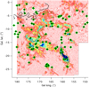 |
Fig. 1 Target stars from our program and from archives superimposed on a 12CO map of the Taurus-Perseus-California area (Dame et al. 2001). Superimposed are HI iso-contours for T(HI) = 1, 2, and 3.5 K (thin, dot-dashed, and thick line lines, respectively), based on HI4PI Collaboration (2016) data. Both CO and HI columns were restricted to LSR velocities between −10 and +10 km s−1. |
2 Spectral data
2.1 TBL Narval data
High resolution, high signal spectra were recorded in service mode with the Narval Echelle spectro-polarimeter at the Bernard Lyot Telescope (TBL) facility during two dedicated programs (L152N07 and L162N04, PI: Lallement). The Narval spectra cover a wide wavelength range from 370 to 1058 nm. Target stars were selected in direction and distance to sample the volumes of Taurus, Perseus, and California clouds, and they were chosen preferentially among the earliest types. The observations were done in the “star only” (pure spectroscopic) mode that provides a resolving power on the order of 75 000. Most of the observations were performed at low airmass.
Spectra of good and excellent quality were obtained for a total of 58 new targets listed in Table A.1. We used the fully reduced and wavelength-calibrated spectra from the Narval pipeline. The pipeline provides the spectrum in separate echelle orders, and here we use the order that covers the ≃764.5–795.0 nm interval and contains the two K I transitions at 7664.911 and 7698.974 Å. The first transition is also included in an adjacent order; however, we used a unique order and non resampled data for the K I extraction. We discuss our reasoning in Sect. 3. This is also valid for the archive Narval and ESPaDOnS data described below. The whole spectrum was used to check for the spectral type, the stellar line widths, and the interstellar Na I absorption lines (see Sect. 4). Further studies of the full set of atomic and molecular absorption lines and of the diffuse interstellar bands are in progress.
2.2 Archival data
We performed an online search in the POLARBASE database and found ten Narval and 15 ESPaDOnS spectra of target stars that have been observed as part of other programs and are suitable for our study. Their spectral resolution R is comprised between ≃ 55 000 and ≃ 85 000, with the lower value for thepolarimetric mode. We also searched for useful spectra in the ESO archive facility and found spectra for seven UVES, two X-shooter, and one FEROS targets of interest (R ≃ 70 000, 18 000, and 80 000 respectively). We also used six spectra from the Chicago database recorded with the ARCES spectrograph at R ≃ 31 000 (Wang et al. 2003; Fan et al. 2019). Finally, one spectrum recorded with the OHP 1.93 m Elodie spectrograph R ≃ 48 000 has been added. Elodie does not cover the K I doublet; however, we derived the Doppler velocity of the main absorbing cloud from neutral sodium lines (5890 Å doublet). All targets and corresponding sources are listed in Table A.1. Heliocentric wavelength scales were either directly provided by the archive facility or derived from the observing date in case of spectra being released in the topocentric reference frame. In the special case of ARCES data, we used the observing date and the telluric features. Finally, in addition to these archival data that entered our telluric correction and profile-fitting, we complemented the observation list with Chaffee & White (1982) Doppler velocities of Taurus clouds for eight targets, also based on neutral potassium lines and high resolution observations. One additional result by Welty et al. (1994) based on sodium lines has also been included. We did not include the WH01 result on HD 23630 (ηTau) and its measured K I radial velocity +7.9 km s−1 due to the target imprecise distance and to redundancy with HD 23512 for which we infer a similar velocity of +7.3 km s−1. The locations of the set of targets are shown in Fig. 1, superimposed on a 12CO map (Dame et al. 2001), here restricted to LSR velocities between −10 and +10 km s−1. A few targets are external to the map and are not shown. Also added are HI 21 cm iso-contours for the same velocity range (HI4PI Collaboration 2016).
3 Spectral analysis
3.1 The dual interstellar and telluric profile-fitting
It is well known that simultaneously fitting two different transitions of the same absorbing species with different oscillator strengths gives additional constraints on the characteristics of the intervening clouds, and it helps to disentangle their respective contributions in the frequent case of overlapping lines. In the case of K I, the stronger transition is located in a spectral region strongly contaminated by telluric O2, and taking advantage of this transition requires taking the O2 absorption profile into account. While, obviously, nothing can be said about the interstellar contribution to the absorption at the bottom of a fully saturated O2 line, in mostcases the interstellar K I absorption or a fraction of it falls in unsaturated parts and contains information. Here we have devised a novel method that allows one to extract all available information contained in the two transitions without using the division by a standard star spectrum or a telluric model prior to the extraction of the interstellar lines. This division creates strong residuals which makes the profile-fitting particularly difficult in the spectral region of the stronger transition and we want to avoid this. The method is made up of two steps. The first step consists in fitting a telluric model to the data and determining the wavelength-dependent LSF. During this step, the spectral regions around the K I lines are excluded. The second step is the dual profile-fitting itself. The previously derived telluric model is multiplied by as many Voigt profiles as necessary to represent the interstellar K I absorption lines and the velocity distribution of intervening clouds, and the total product is convolved by the wavelength-dependent LSF. The number of clouds and the interstellar parameters are optimized to fit this convolved product to the data.
3.2 The preliminary telluric correction and determination of the wavelength-dependent instrumental width
For the telluric correction, we used the TAPAS online facility: TAPAS uses vertical atmospheric profiles of pressure, temperature, humidity, and most atmospheric species, interpolated in the meteorological field of the European Centre for Medium-range Weather Forecasts (ECMWF), the HIgh-Resolution TRANsmission molecular absorption database (HITRAN), and the Line-by-Line Radiative Transfer Model (LBLRTM) software to compute the atmospheric transmission at ultra-high resolution (wavelength step ≃4 × 10⁻⁶ Å). See Bertaux et al. (2014) for details about TAPAS products and all references. Here we use TAPAS calculations for the observatory from which each spectrum under analysis was obtained. From the star spectrum and the TAPAS model, we extracted a wavelength interval of 80 Å containing the K I doublet, for which we performed the following steps. At first we created a Gaussian LSF for an estimated preliminary resolution, adapted to the central wavelength of the correction interval. Via this LSF, we then convolved the initial TAPAS transmission model for one airmass unit, and through cross-correlation we obtained a preliminary Doppler shift between the observed spectrum (data) and this model (convolved TAPAS). To do so, we excluded the potassium lines regions from the Doppler shift estimate, using a mask with null value from 7663 to 7667 and from 7697 to 7701 for both the data and model. We then used a comprehensive list of un-blended or weakly blended telluric O2 lines located in the ≃80 Å interval containing the K I doublet to obtain a first estimate of the airmass at observation as well as a more refined estimate of the spectral resolution. To do so, Gaussian profiles were fitted in both the stellar and Earth transmission spectra at the locations of all these potentially useful lines and the results were compared one-by-one. Undetected lines that are too weak and/or lines with profiles that are too noisy in the data were removed from the list. The strongest lines were selected and all corresponding ratios between the data and model equivalent widths were computed. The average ratio provides a preliminary airmass (or relative optical thickness with respect to the initial model), and the line-width increase between the model and data provides an estimate of the mean resolution.
After all these preparatory steps, the main correction procedure starts. It can be broken down into the following three main steps.
- 1.
The first step involves fitting to the data of the telluric model by means of the rope-length method (see below), masking the central parts of the strong telluric lines (where the flux is close or equal to zero). This step assumes a unique Doppler and a unique Gaussian LSF. The free parameters are the airmass factor, the Doppler shift, and the LSF width.
- 2.
The second step consists of the computation of a decontaminated spectrum by division of the data by the adjusted transmission model and replacement of the ratio by an interpolated polynomial at the locations of the strong telluric lines. This provides a quasi-continuum without strong residuals. By quasi-continuum, we mean the telluric-free spectrum, that is the stellar spectrum and its interstellar features.
- 3.
The third step involves a series of fits of the convolved product of the quasi-continuum and a TAPAS transmission to the data, gradually removing constraints on the width of the instrumental profile and on the Doppler shift, and allowing their variability within the fitted spectral interval, along with the airmass factor variability.
To expand on this, for the first and second steps, we started with the preliminary resolution estimated from the linewidths, and the preliminary O2 column. We then ran an optimization process for afreely varying O2 column (or equivalently a free airmass) and a freely varying LSF width, the convergence criteria being the minimal length of the spectrum obtained after division of the data by the convolved transmission spectrum. Here the length is simply the sum of distances between consecutive data points. Such a technique relies on the fact that the minimum length corresponds to the smoothest curve and therefore to minimum residuals after the data to model ratio, that is to say a good agreement on all the line shapes. It is important to note that this technique is sufficient for weak to moderate lines, but it is applied here only as an intermediate solution (see, e.g., the different situations in Cox et al. 2017; Cami et al. 2018). The third step is adapted to strong lines and corresponds to a forward modeling. We assume that the data, after division by the already well determined atmospheric transmission model, provide the telluric-free continuum outside the strong lines’ centers, andthat the interpolated polynomials may represent at first order the telluric-free data elsewhere. We then performed aseries of fits to the data of convolved products of this adopted continuum by a transmission model, masking theinterstellar K I regions. We let the Doppler shift free to vary along the spectral interval, then, in a final stage, we allowed for a variation of the LSF width. We found that this last stage is very important since the two lines are at very different locations along the echelle order, the first one being very close to the short wavelength limit of the order, and this results in a significant difference reaching a 30% relative variation of the LSF width. We tested the whole procedure for a unique echelle order and for adjacent orders merging. We found that the rebinning and the interpolations required during the order merging as well as the resulting nonmonotonous LSF wavelength variation introduce strong residuals at the locations of the deep lines and make the correction more difficult. Forthis reason, we have chosen to restrict the analysis to one order. After final convergence, we stored the wavelength-dependent LSF width and, importantly, the adjusted transmission model before its convolution by the LSF.
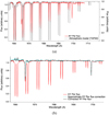 |
Fig. 2 Illustration of the telluric correction, prior to the dual interstellar-telluric profile-fitting. The TAPAS model was selected forthe Pic du Midi observatory. (a) Atmospheric profile (black color, right axis) after adjustment to the observation, superimposed on the initial stellar spectrum (here the star XY Per, red color, left axis). We note that this is the atmospheric profile before convolution by the instrumental profile, which is used at the next step of profile-fitting. (b) Corrected stellar spectrum (black line) obtained by division of the raw data by the above atmospheric profile, after its convolution by the instrumental profile. It is superimposed on the initial stellar spectrum (red line). There are some spiky residuals in the strong absorption areas which are due to the division of weak quantities for both the data and models. Also shown is thequasi-continuum obtained from the corrected spectrum after some interpolation at these regions (turquoise dashed line). Here, the residuals are weak and there is only a very small difference between the two curves. We note that in this figure we want to illustrate the accuracy of the atmospheric model and the achieved level of adjustment: none of these corrected spectra will enter the dual telluric-interstellar profile-fitting, instead only the adjusted preinstrumental profile shown at the top will be used. |
3.3 Application, examples of corrections
This method was applied to all stars, which are listed in Table A.1 on top of the two horizontal lines. A special TAPAS model was used for each separated observatory. An example of telluric model adjustment is represented in Figs. 2a,b. The fitted TAPAS transmission before entrance in the instrument is displayed on top of the data in Fig. 2a. At the end of the process, if we convolve this transmission by the LSF and divide data by the resulting convolved model, we obtain a partially corrected spectrum, represented in Fig. 2b. There are still narrow spikes at the locations of the strongest lines (see e.g., the first pair of O2 lines in Fig. 2b). This is unavoidable in the case of deep lines since the flux in the data and model is close to zero. However, because we did not use the result of the division, but only kept the best telluric model as an ingredient to enter the K I profile-fitting, we are not impacted by such spikes, which is the main advantage of the method. There is an additional advantage: Dividing data by a convolved telluric transmission profile is not a fully mathematically correct solution because the convolution by a LSF of the product of two functions is not equivalent to the product of the two functions separately convolved. The latter computation gives an approximate solution, however, only if all features in the initial spectrum are wider than the LSF. This is not the case in the presence of sharp stellar or interstellar features, and this may have an impact on the accuracy of the results. We note that this type of method can be used in exo-planetary research for the removal of telluric contamination of the spectra obtained from ground-based facilities.
4 Spectral analysis: interstellar K I doublet extraction
4.1 K I doublet extraction method
As a result of the telluric correction procedure, two files were produced for each target, the first one being the fitted TAPAS model, before convolution by the LSF. The second contains the LSF width as a function of wavelength. We used the second to extract the two separate LSFs appropriate for each K I line (7665 and 7700 Å). After this preparation, we then proceeded to the K I doublet profile-fitting in a rather classical manner (see, e.g., Puspitarini & Lallement 2012), except in two ways: (i) the inclusion of the telluric profile, now combined with KI Voigt profiles before convolution by the LSF; and (ii) the use of two distinct LSFs.
The profile-fitting procedure is made up of the following steps:
- 1.
The first step includes the conversion of wavelengths into Doppler velocities for both the stellar spectrum and the fitted transmission model. The correction is done separately for the two K I transitions. We restricted the analysis to spectral regions wide enough to allow a good definition of the two continua.
- 2.
The second step involves continuum fitting with a first, second, or third order polynomial, excluding the interstellar features. The normalization of the spectra at the two transitions was done through division by the fitted continua.
- 3.
The third step consists in the visual evaluation of the minimum number of clouds with distinct Doppler velocities based on the shapes of the K I lines. Markers were placed at the initial guesses for the cloud velocities, using the 7699 Å line.
- 4.
The fourth steps includes fitting to normalized data of convolved products of Voigt profiles and the telluric model by means of a classical Levenberg-Marquardt convergence algorithm in both K I line areas and cloud number increase, if it appears necessary. Here, we have imposed a maximum Doppler broadening (i.e., combination of thermal broadening and internal motions) of 2.5 km s−1 for each cloud. This arbitrary limit was guided by the spectral resolution of the data, the spatial resolution of the present 3D maps of dust, and our limited objectives in the context of this preliminary study (see below).
As is well known, the advantage of fitting a doublet instead of a single line is that more precise cloud disentangling and velocity measurements can be made since there must be agreement between shifts, line depths, and widths for the two transitions and therefore tighter constraints are obtained. An advantage of our technique is obtaining maximal information from the doublet regardless of the configuration of telluric and K I lines. On the other hand, disentangling clumps with velocities closer than ≃2 km s−1 is beyond the scope of this study, which is devoted to a first comparison with 3D dust reconstruction. More detailed profile-fitting combining K I and other species is planned. Accurate measurements of the K I columns for the various velocity components is similarly beyond the scope of this profile-fitting. Despite the use of the K I doublet, such measurements are difficult because the lines are often saturated and the widths of the individual components are generally smaller than the LSF for most of the data. WH01 found a median component width (FWHM) lower than 1.2 km s−1, compared to average values on the order of 3.5 km s−1 for the present data. Here we attempt to use solely the order of magnitude of the measured columns in our search for a counterpart of the absorption in the 3D dust map.
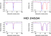 |
Fig. 3 Example of K I doublet dual interstellar-telluric profile-fitting: star HD 24534 (X Per). The spectra are shown around the 7699 (resp. 7665) Å line on the left (resp. on the right). Top graphs: the fitted interstellar model before convolution by the instrumental profile (blue line), superimposed on the raw data. Bottom graphs: the adjusted interstellar-telluric model (blue line) superimposed on the normalized data. For this target, the interstellar K I lines are Doppler shifted out of the strong telluric oxygen lines. |
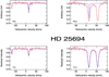 |
Fig. 4 Same as Fig. 3, but for the target star HD 25694. The 7665 Å K I line is blended with one of the telluric oxygen lines. |
4.2 Profile-fitting results
Examples of profile-fitting results are presented in Figs. 3–6. We have selected different situations in terms of locations of the interstellar K I lines with respect to the strong telluric oxygen lines and in terms of cloud numbers. Figure 3 shows a case in which both K I lines are shifted out of the O2 telluric lines and only one strong velocity component is detected. Figure 4 displays a case in which the K I 7664.9 absorption area coincides with the center of a strong O2 telluric line. Still, the inclusion of an interstellar absorption contribution in this area is required to obtain a good adjustment and there is some information gathered from using the doublet instead of the K I 7699 line solely. Figure 5 corresponds to four distinct absorption velocities. Finally, Fig. 6 corresponds to a special case of a star cooler than the majority of other targets and possessing strong K I lines, here fortunately sufficiently Doppler shifted to allow measurements of the moderately shifted Taurus absorption lines.
The profile-fitting results are listed in Table A.2. We note that errors on velocities and K I columns have a limited significance and must be considered cautiously. Due to the partially arbitrary choice of cloud decomposition, our quoted errors on velocities correspond to this imposed choice. It has been demonstrated that there is a hierarchical structure of the dense, clumpy ISM in regions such as Taurus, and that a decomposition into more numerous substructures with relative velocity shifts on the order of 1 km s−1 is necessary if the spectral resolution is high enough (Welty et al. 1994, WH01). However, as we see in the next section, the 3D maps that are presently available do not allow one to disentangle the corresponding clumps that have a few parsec or subparsec sizes and this justifies the choice of our limitations during the profile-fitting. As a consequenceof our allowed line broadening, uncertainties on the central velocities of the clouds may reach up to ≃2 km s−1. We have checked our fitted radial velocities with those measured by WH01 for the targets in common, ζPer, ξPer, and ϵPer, and we found agreement within the uncertainty quoted above by taking our coarser velocity decomposition into account. On the other hand, our quoted errors on the K I columns also correspond to our choices of decomposition and are lower limits. The order of magnitude of the columns is a precious indication for the following step of velocity assignment to structures revealed by the maps.
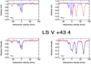 |
Fig. 5 Same as Fig. 3, but for the target star LS V +43 4. 4 individual clouds are necessary to obtain a good fit, i.e., with residuals within the noise amplitude. |
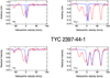 |
Fig. 6 Same as Fig. 3, but for the star TYC-2397-44-1, as an example of profile-fitting in the presence of strong, but Doppler shifted, stellar lines. |
5 Updated 3D dust maps
5.1 Map construction
Massive amounts of extinction measurements toward stars distributed in distance and direction can be inverted to provide the location, in 3D space, of the masses of interstellar dust responsible for the observed extinction. Several methods have been used and the construction of 3D dust maps is in constant progress due the new massive stellar surveys and, especially, due to parallaxes and photometric data from the ESA Gaia mission. Here we use an updated version of the 3D extinction map presented by Lallement et al. (2019), which was based on a hierarchical inversion of extinctions from Gaia DR2 and 2MASS photometric measurements on the one hand, and Gaia DR2 parallaxes on the other hand. The inversion technique here is the same as for this previous map; however, the inverted extinction database and the prior distribution are different. In the case of the construction of the previous map, a homogeneous, plane-parallel distribution was used as the prior. Here, instead, the prior distribution is the previous 3D map itself. The inverted data set is no longer the set of Gaia-2MASS extinctions, instead it is now the extinction database made publicly available by Sanders & Das (2018), and it is slightly augmented by the compilation of nearby star extinctions used in Lallement et al. (2014). With the goal of deriving their ages for a large population of stars, Sanders & Das (2018) have analyzed, in a homogeneous way, data from six stellar spectroscopic surveys, APOGEE, GALAH, GES, LAMOST, RAVE, and SEGUE, and they estimated the extinction for a series of 3.3 million targets (if the catalog is restricted to the “best” flag, see Sanders & Das 2018). To do so, and in combination with the parameters inferred from the spectroscopic data, they used the photometric measurements from various surveys and in a large number of bands (J, H, and K from 2MASS; G, GBP, and GRP from Gaia; gP, rP, and iP from Pan-STARRS; g, r, and i from SDSS; and Jv, Hv, and Kv from VISTA). They used a Bayesian model and priors on the stellar distributions as well as priors on the extinction derived from the Pan-STARRS 3D mapping (Green et al. 2018) or the large-scale model from Drimmel et al. (2003). Because the extinction determined by Sanders & Das (2018) is in magnitude per parsec in the V band, and since our prior map was computed as A0 (i.e., the mono-chromatic extinction at 5500 Å), we applied a fixed correction factor to the prior distribution of differential extinction, a factor deduced from cross-matching A0 extinctions used for this prior and the extinctions of Sanders & Das (2018) for targets in common. Due to the strong constraints brought by the spectroscopic information, the individual extinctions from the Sanders & Das (2018) catalog are more accurate than purely photometric estimates, and they are expected to allow one to refine the 3D mapping. This is why the minimal spatial correlation kernel for this new inversion, a quantity that corresponds to the last iteration of the hierarchical scheme, is 10 pc, compared to the 25 pc kernel of the Gaia-2MASS map (see Vergely et al. 2010 for details on the basic principles as well as limitations of the inversion, and see Lallement et al. 2019 for a description of the hierarchical inversion scheme). We note, however, that because the whole set of spectroscopic surveys is far from homogeneously covering all directions and distances, such a spatial resolution is not achievable everywhere and, in the case of regions of space that are not covered, the computed solution remains the one of the prior 3D map.
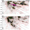 |
Fig. 7 Images of the inverted dust distribution in two vertical planes containing the Sun (located at 0,0) and oriented along Galactic longitudes of l = 160 and 172 degrees. Galactic latitudes are indicated by dashed black lines, every 5 degrees from b = 0 in the plane to b = −90 (South Galactic pole). Coordinates are in parsecs. The quantity represented in black and white is the differential extinction dAV/dl at each point. Isocontours are shown for 0.0002,0.00045, 0.001, 0.002, 0.005, 0.01, 0.015, and 0.02 mag per parsec. Superimposed are the closest and farthest locations of the molecular clouds from the Zucker et al. (2020) catalog that are at longitudes close to the one of the image (see text). A dashed pink line connects these two locations for each cloud. |
5.2 Taurus dust clouds in 3D
The Taurus area has been quite well covered by the spectroscopic surveys used by Sanders & Das (2018), in particular APOGEE and LAMOST (Majewski et al. 2017; Deng et al. 2012). This has allowed a more detailed mapping of the dust clouds in this region and justifies the use of the updated map for our kinetic study. In Fig. 7 we show images of the newly computed differential extinction in two planes perpendicular to the mid-plane and containing the Sun, oriented along Galactic longitudes of 160 and 172°, respectively. The color-coded quantity is the local differential extinction, or extinction per distance, a quantity highly correlated with the dust volume density. As mentioned above, an important characteristic of the maps and images is the minimum size of the cloud structures, directly connected to the minimum spatial correlation kernel imposed during the inversion. In the Taurus area, thanks to the target density the kernel is on the order of 10 pc almost everywhere in the regions of interest up to ≃500 pc. We havecompared the locations of the dense structures reconstructed in Taurus, Perseus, and California with results on individual molecular cloud distances in the recent catalog of Zucker et al. (2020), based on PanSTARRS and 2MASS photometricdata on the one hand, and Gaia DR2 parallaxes on the other hand. Superimposed on the first image along l = 160° (resp. 172°) are the closest and farthest locations of the clouds as measured by Zucker et al. (2020), restricting their list to cloud center longitudes comprised between 156 and 164° (resp. 166 and 176°). This implies that, here, we neglect the difference of up to 4° between the molecular cloud actual longitudes and the longitude of the vertical plane. We also solely used the statistical uncertainties on the distances quoted by Zucker et al. (2020), and we did not add the systematic uncertainty of 5% quoted by the authors. Despite these differences and reduced uncertainties, and despite our limited spatial resolution required by the full-3D inversion technique, it can be seen in Fig. 7 that there is good agreement between the locations of the dense structures obtained by inversion and the locations independently obtained by Zucker et al. (2020).
As mentioned in the introduction, large amounts of YSOs can now be identified and located in 3D space, and several studies have been devoted to their clustering and associations with known molecular clouds (Großschedl et al. 2021; Roccatagliata et al. 2020; Kounkel et al. 2018; Galli et al. 2019). If the stars are young enough, they remain located within their parent cloud and their proper motions are identical to the motion of the cloud. As an additional validation of the new 3D dust distribution, we have superimposed the locations of the Main Taurus YSO clusters found by Galli et al. (2019) in the dust density images used for the preliminary 3D kinetic tomography presented in the next section. The locations of these YSO clusters are also, in principle, those of the associated molecular clouds. L 1517/1519, L 1544, L 1495 NW, L 1495, B 213/216, B 215, Heiles Cloud 2, Heiles Cloud 2NW, L 1535/1529/1531/1524, L 1536, T Tau cloud, L 1551, and L 1558 are the main groups identified by the authors and are shown in Figs. 10–12. Although the dust map spatial resolution is not sufficient to disentangle close-by clouds, it can be seen from the series of figures that the YSO clusters coincide with very dense areas.
5.3 Link between extinction and K I absorption strength
Most of our targets do not have individually estimated extinctions. However, it is possible to use the 3D distribution of differential extinction and to integrate this differential extinction along the path between the Sun and each target star to obtain an estimate of the star extinction. We performed this exercise for our series of targets and compared the resulting extinctions AV with the full equivalent widths of the 7699 Å K I absorption profiles. The comparison is shown in Fig. 8. Despite an important scatter, there is a clear correlation between the two quantities, a confirmation of the link between neutral potassium and dust as well as a counterpart of the link between K I and the H column shown by WH01. We note that we do not expect a tight correlation between the two quantities for several reasons. One of the reasons is the limited resolution of the map, and the fact that the extinction is distributed in volumes on the order of the kernel. As a consequence, high density regions in cloud cores are smeared out and high columns that occur for lines of sight crossing such cores have no comparably high counterparts in the integrations. A second reason is the distance uncertainty. Despite their unprecedented accuracy, Gaia EDR3 uncertainties are on the order of a few parsec for the Taurus targets and this may influence the integral. An additional source of variability of a different type is the nonlinear relationship between the equivalent width we are using here and the column of atoms, and its dependence on the temperature, turbulence, and velocity structure (see, e.g., WH01). In order to compare the links between K I and H columns on the one hand, and between K I and dust columns on the other hand, we have used the 7699 Å K I equivalent widths measured by WH01 and we have converted Htot columns taken from the same study into extinctions, assuming a constant ratio and AV = 1 for N(Htot) = 6. 1021/3.1 cm−2. Figure 8 displays the relationship between the two quantities, superimposed on our values of equivalent widths and extinctions. The scatter appears to be similar, as confirmed by the similarity of the Pearson correlation coefficients, 0.74 for our results and 0.72 for the quantities derived from the WH01 study. This suggests that, as expected, the link of K I with dust is comparable to its link with H. We note that our 105 data points correspond to Taurus stars, while the 35 ratios using K I and N(Htot) from WH01 correspond to stars distributed over the sky. The average ratio between extinction and K I is smaller in our case, a large part of the difference is certainly linked to our limited spatial resolution and the corresponding smearing of the extinction. In the context of kinetic tomography, the obtained relationship is encouraging and it suggests that K I absorptions may be a convenient tool.
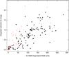 |
Fig. 8 Integrated extinction between the Sun and each target, using the 3D map, as a function of the full equivalent width of the 7699 Å K I absorption profile (black signs). Also shown are 7699Å K I equivalent widths from WH01 and extinctions estimated from the conversion of H columns (red signs, see text). |
6 Preliminary 3D kinetic study
Our objective here is to study which constraints are brought about by our relatively small number of K I measurements in the context of kinetic tomography, more precisely what velocity assignments can be made to dense structures reconstructed in 3D by extinction inversion, using the measured absorption velocities and our most recent 3D dust maps exclusively. We started, by extracting from the 3D distribution of differential extinction, a series of images of dust clouds in vertical planes containing the Sun and oriented toward Galactic longitudes distributed between l = 150 and l = 182°, by steps of 2.5°, with the exception of l = 152.5°, due to the absence of targets, that is images similar to those in Fig. 7, now covering the whole Taurus-Perseus-California regions. About these images, it is important to keep in mind that the mapped structures have a minimum size of 10 pc, which prevents detecting smaller clumps. We used this set of images, the paths to the target stars, and the absorption results to link, in a nonautomated way, dust concentrations and velocities, plane after plane. To do this, for each image of the vertical plane, we selected the target stars whose longitudes are less than 1.3 degrees from the longitude of the plane and we plotted the projection of their line of sight on the plane. We did this for their most probable distance, in all cases available from the Gaia Early Data Release 3 (EDR3) catalog (Gaia Collaboration 2021) except for two targets. We then compared their observed K I absorption velocities as well as their associated approximate columns (in units of 1010 cm−2) and the dense structures encountered along their trajectories. As we have already pointed out, this exercise would take too much time in the case of more numerous data and the results are partially arbitrary, but we want to illustrate here what can be done based only on a preliminary visual method. Work is underway to develop automated techniques.
Figure 9 displays the vertical plane along l = 150°. Planes along other longitudes are displayed in Figs. 10–12. In each figure, we restrict ourselves to radial velocities measured for stars with longitudes within 1.3° from the plane, listed at the bottom. To help visualize which star corresponds to which velocity assignment, we have numbered them and the numbers correspond to the objects listed in the text included in each figure. The velocity assignments to the dense clouds are indicated by arrows pointing outward (inward) for positive (negative) radial velocities. The length of the arrow is proportionalto the velocity modulus. Two or more velocities at very close locations in the map indicate that information on the same cloud is provided by different stars. In some cases the arrows are slightly displaced to avoid the superimposition of different measurements based on stars at very close latitudes. In all cases, differences between measured velocities on the order of 1 km s−1 and sometimes up to 2 km s−1 may be due to profile-fitting uncertainties and do not necessarily imply a different clump.
The first result is linked to the exercise itself: it was surprisingly easy to associate velocities and clouds. For all K I columns on the order or above ≃5 × 1010 cm−2, dense structures are found along the corresponding path to the target star and the cases with multiple velocities frequently offered obvious solutions. In general, K I starts to get detected for lines of sight that are crossing the 0.005 mag pc−1 differential extinction iso-contour, although this approximate threshold varies as a function of the distance to the plane and the signal-to-noise ratio (S/N) of the recorded spectrum. There is consistency between the near side of the reconstructed Main Taurus dust clouds and the distances to the targets with detected absorption. The closest star with detected K I is HD 26873 at 123.5 ± 1.3 pc, followed by HD 25204 at 124 ± 6.8 pc and DG Tauat 125.3 ± 2 pc. Only HD 23850 at 123.2 ± 7.3 pc has a smaller parallax distance, but the uncertainty on its distance is significant. Similarly, HD 280026 has no detected neutral potassium, but deep 5890 Å sodium absorption despite the most probable distance as short as 103 pc. However, there is no DR2 nor EDR3 Gaia parallax value, and this unique distance estimate is based on Hipparcos, with a large associated uncertainty of 30 pc. As a conclusion, it is likely that these last two targets are located within the near side boundary of the Taurus complex, probably in the atomic phase envelop and very close to the molecular phase at ≃123 pc. These are encouraging results, showing that the 3D maps, the distances, and the velocity measurements are now reaching a quality that is actually allowing kinetic tomography. In many cases the assignment is not questionable (see, e.g., the star 55 in the l = 165° image). In other numerous cases, the assignment based on one star strongly influences the solution for other stars. Finally, since there is continuity in the velocity pattern in consecutive planes, several consecutive planes can be used to follow both the shape and velocity changes of the same large structure.
We now discuss the results in more detail, plane by plane. The l = 150° image shows two dense structures at 145 and 400 pc and a weaker cloud at 250 pc. Interestingly, the three distances are similar to the distances to Main Taurus, California, and Perseus, but these opaque regions are located much closer to the Galactic plane than the well known dense clouds. As can be seen from all figures (see, e.g., Fig. 10), this triple structure is still present at higher longitudes up to l = 170 °. In the l = 150° plane, a radial velocity decrease with distance, from ≃+5 down to ≃ − 8 km s−1, is clearly associated with these three groups, that is to say there is a compression of the whole region along the radial direction. The intermediate structure at 250 pc has a very small or null LSR radial velocity. The l = 155° image confirms the velocity pattern (despite the small number of stars) and starts to show the densest cloud complexes, which are better represented in the next vertical planes. Perseus reaches a maximal density at l ≃ 157.5 and, at this longitude, is connected to a series of structures located between 250 and 320 pc and reaching the Galactic Plane. California is the most conspicuous structure at l ≃ 160–162 °, and it starts to be divided into two main parts at l ≃ 162°, the most distant one reaching 540 pc. Along l = 157.5°, the global velocity pattern slightly changes, with the appearance of a positive velocity gradient between Main Taurus and Perseus. The structure at 320 pc (above Perseus in the image) is peculiar, with a larger positive radial velocity (marked by a question mark), but further measurements are required to conclude. In the l = 157.5° and l = 160° images, we have located the dense molecular clouds L1448, L1451, and IC348 in Perseus at their distances found by Zucker et al. (2018) and we have compared the radial velocities we can assign to L1448 and IC348 with the radial velocities deduced by the authors based on CO data and 3D extinction. From the strong absorption toward BD+30 540 (star 48) and unambiguously assigned to the region with maximal opacity that corresponds to L1448, we derived Vr = +5 km s−1 for this cloud, close to the 4.8 km s−1 peak-reddening radial velocity of Zucker et al. (2018). From several targets crossing the IC348 area (see the next l = 160° plane), we derived Vr ≃ +8 km s−1 for IC348, which is close to their average velocity of +8.5 km s−1. Still in the l = 160° plane, the structure in the foreground of IC348 at ≃140 pc (a distance in agreement with Zucker et al. (2018), see their Fig. 6) appears to have a complex velocity structure with smaller velocities for the dense central region. However, again, more data is needed to better map and quantify this property. California at 450 pc is characterized by a decreasing modulus of the inward motion with increasing distance from the Galactic plane.
In the l = 165° vertical plane, one starts to see the disappearance of California and Perseus, and the change in California radial velocities, from negative to null values at about 480 pc. In this image and all the following ones (up to l = 182.5. °), the main, densest areas of Main Taurus are the most interesting structures. The YSO clusters derived by Galli et al. (2019) in Taurus are found to be located in the densest parts, and the maps confirm the distribution in radial distance of the densest areas found by the authors and previous works, from 130 to 160 pc in the case of all clouds at latitudes below the b ≃ −7° area. An interesting result is the existence of a series of measurements of small radial velocities we could associate with the most distant parts of the clouds (see the four images in Fig. 11). We cannot distinguish these velocities from the main flow in all stars, only excellent signal-to-noise and spectral resolution allow one to do it; however, their numbers strongly suggest the existence of a negative gradient directed outward, and this compression is very likely connected to the large number of star-forming regions in this area. The case of L1558 is peculiar. It is the only well known structure found to be located in a moderately dense area; however, this may be an imperfection of the map due the lack of stars because it is located behind a particularly opaque area. From the point of view of the kinematics, we have used the positions and velocities in Cartesian coordinates of Galli et al. (2019) to compute the radial velocities in heliocentric and LSR frame, and we compared the results with our assignments when possible. The results are found to be compatible within 1.5 km s−1. For L1495 (l = 170° figure), the most appropriate measurement is for star 74, with a velocity of +7.4 km s−1 for the main component, which is the closest to the Sun. According to Galli et al. (2019), the radial velocity of the cluster is +6.9 km s−1. For B215, we can use several stars that provide velocities of +8, +8.5, +7.2, +5.8, and +6.5 km s−1, that is an average of ≃+7km s−1, while the estimated value of Galli et al. (2019) is +7.5 km s−1. For L1517-1519, we can use star 9 with +6.3 km s−1, while the authors find +4.8 km s−1. For L1536, our low velocity value from star 65 is +4.9 km s−1, which is compatible with +5.9 km s−1. For T Tau, we can use the target star 23, which has two components at +7 and +12 km s−1. The cluster found by Galli et al. (2019) is apparently located on the more distant, low velocity side with a value of +7.8 km s−1. About L1544, star 44 has its high velocity component at +6.3 km s−1, which is compatible with the +7.6 km s−1 found for the cluster. For all these cases, the comparisons seem to confirm the negative velocity gradient we have discussed above, that is to say a general compression and deceleration along the radial direction. L1551 does not follow the rule and there is no agreement between our estimated velocity pattern and the result from Galli et al. (2019): if the cluster and associated cloud is located as is shown in the l = 180° plane, it should be within the high velocity part of the two regions probed by star 7, that is at +8.4 km s−1; however, its velocity of +5.6 km s−1 is closer to the low velocity component detected for this star, +4.1km s−1. On the other hand, in this very thick region, the velocity pattern may be more complex and it may require more constraints.
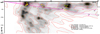 |
Fig. 9 Imageof the inverted dust distribution in a vertical plane containing the Sun (located at 0,0) and oriented along Galactic longitude l = 150°. Coordinates are in parsecs. The quantity represented in black and white is the differential extinction. Iso-contours are shown for 0.0002, 0.00045, 0.001, 0.002, 0.005, 0.01, 0.015, and 0.02 mag per parsec. The paths to the target stars whose longitudes are within 1.3 degrees from the longitude of the represented plane are superimposed. The stars are numbered as in the text and drawn at the bottom of the figure; additionally, the Doppler velocities and approximate columns of absorbing K I in 1010 cm−2 units are listed for each target (in parentheses after velocities). Stars’ numbers are indicated in yellow or black. The list of targets is given by decreasing latitude. For distant targets falling outside the image, their numbers are indicated along their paths at the boundary of the figure. The preliminary velocity assignments to the dense clouds are indicated by arrows pointing outward (inward) for positive (negative) radial velocities. The length of the arrow is proportional to the velocity modulus. |
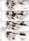 |
Fig. 10 Same as Fig. 9, but for longitudes l = 155, 157.5, 160, and 162.5°. For pink markers see text. |
7 Conclusions and perspectives
We have investigated the link between interstellar K I absorption and dust opacity, and we tested the use of K I absorption data in the context of 3D kinetic tomography of the ISM. To do so, we have obtained and analyzed high-resolution stellar spectra of nearby and mainly early-type stars in the Taurus-Perseus-California area, recorded with the Narval spectrograph at TBL/Pic du Midi. We have developed a new technique based on synthetic atmospheric transmission profiles that allows us to extract a maximum of information from the interstellar K I absorption doublet and we have applied the new technique to the Narval data as well as to archival data, mainly high-resolution spectra from the Polarbase archive. Atmospheric profiles were downloaded from the TAPAS facility for each observing site and adjusted to the data. During the adjustment, the instrumental width and its variation with wavelength was derived. A new interstellar-telluric profile-fitting using Voigt profiles in a classical way and the previously derived telluric profile was performed and the radial velocities of the main absorbing interstellar clouds were derived. The adjustment used the measured LSFs, one for each transition of the doublet. We present the results of this profile-fitting for 108 targets, complemented by results from the literature for eight additional stars.
In parallel, we computed an updated 3D distribution of interstellar dust, based on the inversion of a large catalog of extinction measurements for stars distributed at all distances. The maps were obtained in a similar way as the one based on Gaia/2MASS presented in Lallement et al. (2019), but the inverted data set was the extinction catalog computed by Sanders & Das (2018) as an auxiliary product of their study on stellar ages, augmented by the small compilation of nearby star extinctions used in Lallement et al. (2014). Importantly, instead of an initial, homogeneous, plane-parallel prior, the new prior was the Gaia-2MASS map itself. As a result, in regions that are not covered by the spectroscopic surveys analyzed by Sanders & Das (2018), the recovered 3D distribution is the unchanged prior, that is the Gaia/2MASS map, and in areas covered by the surveys there is additional information from the combination of spectral and photometric information. The spatial resolution of the dust maps is limited by the target star density and the correlation length imposed in the inversion. Here, the last iteration was done for a 10 pc wide kernel, and this implies that the recovered dust masses are spread out over volumes on the order of 10 pc or more.
As a first test of the link between K I and dust opacity, we compared the equivalent width of the 7699 Å absorption with the integral of the differential extinction between the Sun and the target star throughout the new 3D map. The relationship between the two quantities is compared with the results of WH01 for K I and the H column (HI +2 H2) and we obtain similar correlation coefficients. This confirms that neutral potassium is tracing both atomic and molecular phases in dense structures. Based on the comparison between the dust cloud distribution and the absorption velocities, we have made a preliminary assignment of radial velocities to the dense structures showing up in the maps. According to the above description, our study had several limitations: the limited number of lines of sight (≃120 targets); the limited spatial resolution of the maps (≃10 pc); and the partially arbitrary decomposition of K I absorption profiles into discrete clouds, leading to a minimum velocity difference on the order of 1–2 km s−1. However, despite of these limitations, we found that, except for very few measurements, it was possible and relatively easy to find a coherent solution for the connections between clouds and velocities, with some continuity in the direction and distance for the velocity field. Large-scale spatial gradients were retrieved, and some internal gradients could be determined. We present images of the dust distribution in a series of vertical planes containing the Sun and oriented along Galactic longitudes from 150 to 182.5°. Proposed velocity assignments and paths to the used target stars are indicated in each image, allowing one to visualize the velocity pattern and check the sources of the constraints. We show several comparisons between our maps and velocity assignments with the locations of the molecular cloud and young star clusters and their radial velocities from recent works by Zucker et al. (2018, 2020) and Galli et al. (2019). There is a good agreement between both positions and radial velocities.
This study shows that it is possible to obtain a first, spatially coherent 3D kinetic tomography of the ISM in out-of-plane nearby regions, using solely dust maps and K I absorption data. Such a preliminary tomography can be used as a prior solution for more ambitious, automated kinetic tomography techniques, using dust maps in combination with emission data, and/or with massive amounts of absorption data from future surveys. It shows that K I absorptions can also be a very efficient tool to check or validate tomographic results based on other absorption or emission spectral data. A main advantage of using K I as a tracer of Doppler velocities is the sharpness of the absorption lines and the resulting optimal disentangling of multiple clouds, at variance with DIBs that are broad. DIBs have already proven to be useful tools for kinetic measurements in the visible (e.g., Puspitarini et al. 2015), but they are most useful in the infrared wavelength range due to better access to a target beyond opaque regions (Zasowski & Ménard 2014; Zasowski et al. 2015; Tchernyshyov et al. 2018). In this respect, they are superior to K I. On the other hand, another advantage of K I, as quoted above, is its association with both atomic and molecular phases, as shown by WH01, and extrapolated here to the dust opacity. For this reason, K I will be particularly well adapted to kinetic tomography using dust maps and devoted to extended regions consisting of both phases, including dense gas reservoirs devoid of CO. Ultimately, 3D kinetic tomography may be best achieved through the combination of various tracers, ideally in absorption and emission, and, obviously, using all results directly or indirectly related to Gaia catalogs. In all cases, assigning velocities to structures seen in 3D would allow one to link the structures to emission lines that possess particularly rich information on physical and chemical mechanisms at work and to shed light on evolutionary processes.
Acknowledgements
R.L. deeply thanks the Pic du Midi TBL staff for his efficiency and assistance. We greatly appreciated the constructivecomments and also the criticisms of our referee, which led to a significant improvement of the article. A.I. wants to acknowledgethe support of Ministry of Science and Higher Education of the Russian Federation under the grant 075-15-2020-780 (N13.1902.21.0039). J.L. Vergely acknowledges support from the EXPLORE project. EXPLORE has received funding from the European Union’s Horizon 2020 research and innovation programme under grant agreement No 101004214. This research has made use of the SIMBAD database, operated at CDS, Strasbourg, France.
Appendix A Tables
Targets.
Velocity table.
References
- Anders, F., Khalatyan, A., Chiappini, C., et al. 2019, A&A, 628, A94 [NASA ADS] [CrossRef] [EDP Sciences] [Google Scholar]
- Antoja, T., Helmi, A., Romero-Gómez, M., et al. 2018, Nature, 561, 360 [NASA ADS] [CrossRef] [Google Scholar]
- Bailer-Jones, C. A. L., Rybizki, J., Fouesneau, M., Demleitner, M., & Andrae, R. 2021, AJ, 161, 147 [Google Scholar]
- Bertaux, J. L., Lallement, R., Ferron, S., Boonne, C., & Bodichon, R. 2014, A&A, 564, A46 [NASA ADS] [CrossRef] [EDP Sciences] [Google Scholar]
- Cami, J., Cox, N. L., Farhang, A., et al. 2018, The Messenger, 171, 31 [NASA ADS] [Google Scholar]
- Chaffee, F. H., J., & White, R. E. 1982, ApJS, 50, 169 [NASA ADS] [CrossRef] [Google Scholar]
- Chen, B. Q., Huang, Y., Yuan, H. B., et al. 2019, MNRAS, 483, 4277 [NASA ADS] [CrossRef] [Google Scholar]
- Cox, N. L. J., Cami, J., Farhang, A., et al. 2017, A&A, 606, A76 [NASA ADS] [CrossRef] [EDP Sciences] [Google Scholar]
- Dame, T. M., Hartmann, D., & Thaddeus, P. 2001, ApJ, 547, 792 [NASA ADS] [CrossRef] [Google Scholar]
- Deng, L.-C., Newberg, H. J., Liu, C., et al. 2012, Res. Astron. Astrophys., 12, 735 [NASA ADS] [CrossRef] [Google Scholar]
- Donati, J. F., Semel, M., Carter, B. D., Rees, D. E., & Collier Cameron, A. 1997, MNRAS, 291, 658 [NASA ADS] [CrossRef] [MathSciNet] [Google Scholar]
- Drimmel, R., Cabrera-Lavers, A., & López-Corredoira, M. 2003, A&A, 409, 205 [NASA ADS] [CrossRef] [EDP Sciences] [Google Scholar]
- Fan, H., Hobbs, L. M., Dahlstrom, J. A., et al. 2019, ApJ, 878, 151 [NASA ADS] [CrossRef] [Google Scholar]
- Gaia Collaboration (Brown, A. G. A., et al.) 2021, A&A 649, A1 [NASA ADS] [CrossRef] [EDP Sciences] [Google Scholar]
- Galli, P. A. B., Loinard, L., Bouy, H., et al. 2019, A&A, 630, A137 [NASA ADS] [CrossRef] [EDP Sciences] [Google Scholar]
- Green, G. M., Schlafly, E. F., Finkbeiner, D., et al. 2018, MNRAS, 478, 651 [NASA ADS] [CrossRef] [Google Scholar]
- Green, G. M., Schlafly, E., Zucker, C., Speagle, J. S., & Finkbeiner, D. 2019, ApJ, 887, 93 [Google Scholar]
- Großschedl, J. E., Alves, J., Meingast, S., & Herbst-Kiss, G. 2021, A&A, 647, A91 [CrossRef] [EDP Sciences] [Google Scholar]
- Guo, H. L., Chen, B. Q., Yuan, H. B., et al. 2021, ApJ, 906, 47 [CrossRef] [Google Scholar]
- Haywood, M., Snaith, O., Lehnert, M. D., Di Matteo, P., & Khoperskov, S. 2019, A&A, 625, A105 [CrossRef] [EDP Sciences] [Google Scholar]
- Helmi, A. 2020, ARA&A, 58, 205 [Google Scholar]
- HI4PI Collaboration (Ben Bekhti, N., et al.) 2016, A&A, 594, A116 [NASA ADS] [CrossRef] [EDP Sciences] [Google Scholar]
- Hottier, C., Babusiaux, C., & Arenou, F. 2020, A&A, 641, A79 [CrossRef] [EDP Sciences] [Google Scholar]
- Katz, D., Gomez, A., Haywood, M., Snaith, O., & Di Matteo, P. 2021, A&A, submitted [arXiv:2102.02082] [Google Scholar]
- Khoperskov, S., Gerhard, O., Di Matteo, P., et al. 2020, A&A, 634, L8 [Google Scholar]
- Khoperskov, S., Haywood, M., Snaith, O., et al. 2021, MNRAS, 501, 5176 [NASA ADS] [CrossRef] [Google Scholar]
- Kounkel, M., Covey, K., Suárez, G., et al. 2018, AJ, 156, 84 [NASA ADS] [CrossRef] [Google Scholar]
- Lallement, R., Vergely, J.-L., Valette, B., et al. 2014, A&A, 561, A91 [NASA ADS] [CrossRef] [EDP Sciences] [Google Scholar]
- Lallement, R., Babusiaux, C., Vergely, J. L., et al. 2019, A&A, 625, A135 [NASA ADS] [CrossRef] [EDP Sciences] [Google Scholar]
- Leike, R. H., Glatzle, M., & Enßlin, T. A. 2020, A&A, 639, A138 [NASA ADS] [CrossRef] [EDP Sciences] [Google Scholar]
- Majewski, S. R., Schiavon, R. P., Frinchaboy, P. M., et al. 2017, AJ, 154, 94 [NASA ADS] [CrossRef] [Google Scholar]
- Petit, P., Louge, T., Théado, S., et al. 2014, PASP, 126, 469 [Google Scholar]
- Pety, J., Guzmán, V. V., Orkisz, J. H., et al. 2017, A&A, 599, A98 [NASA ADS] [CrossRef] [EDP Sciences] [Google Scholar]
- Puspitarini, L., & Lallement, R. 2012, A&A, 545, A21 [NASA ADS] [CrossRef] [EDP Sciences] [Google Scholar]
- Puspitarini, L., Lallement, R., Babusiaux, C., et al. 2015, A&A, 573, A35 [NASA ADS] [CrossRef] [EDP Sciences] [Google Scholar]
- Queiroz, A. B. A., Anders, F., Chiappini, C., et al. 2020, A&A, 638, A76 [CrossRef] [EDP Sciences] [Google Scholar]
- Rezaei Kh., S., Bailer-Jones, C. A. L., Soler, J. D., & Zari, E. 2020, A&A, 643, A151 [EDP Sciences] [Google Scholar]
- Roccatagliata, V., Franciosini, E., Sacco, G. G., Randich, S., & Sicilia-Aguilar, A. 2020, A&A, 638, A85 [CrossRef] [EDP Sciences] [Google Scholar]
- Sanders, J. L., & Das, P. 2018, MNRAS, 481, 4093 [Google Scholar]
- Sharma, S., Hayden, M. R., & Bland-Hawthorn, J. 2020, ArXiv e-prints [arXiv:2005.03646] [Google Scholar]
- Tchernyshyov, K., & Peek, J. E. G. 2017, AJ, 153, 8 [NASA ADS] [CrossRef] [Google Scholar]
- Tchernyshyov, K., Peek, J. E. G., & Zasowski, G. 2018, AJ, 156, 248 [CrossRef] [Google Scholar]
- Vergely, J.-L., Valette, B., Lallement, R., & Raimond, S. 2010, A&A, 518, A31 [NASA ADS] [CrossRef] [EDP Sciences] [Google Scholar]
- Wang, S.-i., Hildebrand, R. H., Hobbs, L. M., et al. 2003, SPIE Conf. Ser., 4841, 1145 [Google Scholar]
- Welty, D. E., & Hobbs, L. M. 2001, ApJS, 133, 345 [NASA ADS] [CrossRef] [Google Scholar]
- Welty, D. E., Hobbs, L. M., & Kulkarni, V. P. 1994, ApJ, 436, 152 [NASA ADS] [CrossRef] [Google Scholar]
- Zasowski, G., & Ménard, B. 2014, in The Diffuse Interstellar Bands, eds. J. Cami, & N. L. J. Cox (Cambridge: Cambridge University Press), 297, 68 [Google Scholar]
- Zasowski, G., Ménard, B., Bizyaev, D., et al. 2015, ApJ, 798, 35 [Google Scholar]
- Zucker, C., Schlafly, E. F., Speagle, J. S., et al. 2018, ApJ, 869, 83 [NASA ADS] [CrossRef] [Google Scholar]
- Zucker, C., Speagle, J. S., Schlafly, E. F., et al. 2020, A&A, 633, A51 [CrossRef] [EDP Sciences] [Google Scholar]
Distance from Bailer-Jones et al. (2021)
All Tables
All Figures
|
Fig. 1 Target stars from our program and from archives superimposed on a 12CO map of the Taurus-Perseus-California area (Dame et al. 2001). Superimposed are HI iso-contours for T(HI) = 1, 2, and 3.5 K (thin, dot-dashed, and thick line lines, respectively), based on HI4PI Collaboration (2016) data. Both CO and HI columns were restricted to LSR velocities between −10 and +10 km s−1. |
| In the text | |
|
Fig. 2 Illustration of the telluric correction, prior to the dual interstellar-telluric profile-fitting. The TAPAS model was selected forthe Pic du Midi observatory. (a) Atmospheric profile (black color, right axis) after adjustment to the observation, superimposed on the initial stellar spectrum (here the star XY Per, red color, left axis). We note that this is the atmospheric profile before convolution by the instrumental profile, which is used at the next step of profile-fitting. (b) Corrected stellar spectrum (black line) obtained by division of the raw data by the above atmospheric profile, after its convolution by the instrumental profile. It is superimposed on the initial stellar spectrum (red line). There are some spiky residuals in the strong absorption areas which are due to the division of weak quantities for both the data and models. Also shown is thequasi-continuum obtained from the corrected spectrum after some interpolation at these regions (turquoise dashed line). Here, the residuals are weak and there is only a very small difference between the two curves. We note that in this figure we want to illustrate the accuracy of the atmospheric model and the achieved level of adjustment: none of these corrected spectra will enter the dual telluric-interstellar profile-fitting, instead only the adjusted preinstrumental profile shown at the top will be used. |
| In the text | |
|
Fig. 3 Example of K I doublet dual interstellar-telluric profile-fitting: star HD 24534 (X Per). The spectra are shown around the 7699 (resp. 7665) Å line on the left (resp. on the right). Top graphs: the fitted interstellar model before convolution by the instrumental profile (blue line), superimposed on the raw data. Bottom graphs: the adjusted interstellar-telluric model (blue line) superimposed on the normalized data. For this target, the interstellar K I lines are Doppler shifted out of the strong telluric oxygen lines. |
| In the text | |
|
Fig. 4 Same as Fig. 3, but for the target star HD 25694. The 7665 Å K I line is blended with one of the telluric oxygen lines. |
| In the text | |
|
Fig. 5 Same as Fig. 3, but for the target star LS V +43 4. 4 individual clouds are necessary to obtain a good fit, i.e., with residuals within the noise amplitude. |
| In the text | |
|
Fig. 6 Same as Fig. 3, but for the star TYC-2397-44-1, as an example of profile-fitting in the presence of strong, but Doppler shifted, stellar lines. |
| In the text | |
|
Fig. 7 Images of the inverted dust distribution in two vertical planes containing the Sun (located at 0,0) and oriented along Galactic longitudes of l = 160 and 172 degrees. Galactic latitudes are indicated by dashed black lines, every 5 degrees from b = 0 in the plane to b = −90 (South Galactic pole). Coordinates are in parsecs. The quantity represented in black and white is the differential extinction dAV/dl at each point. Isocontours are shown for 0.0002,0.00045, 0.001, 0.002, 0.005, 0.01, 0.015, and 0.02 mag per parsec. Superimposed are the closest and farthest locations of the molecular clouds from the Zucker et al. (2020) catalog that are at longitudes close to the one of the image (see text). A dashed pink line connects these two locations for each cloud. |
| In the text | |
|
Fig. 8 Integrated extinction between the Sun and each target, using the 3D map, as a function of the full equivalent width of the 7699 Å K I absorption profile (black signs). Also shown are 7699Å K I equivalent widths from WH01 and extinctions estimated from the conversion of H columns (red signs, see text). |
| In the text | |
|
Fig. 9 Imageof the inverted dust distribution in a vertical plane containing the Sun (located at 0,0) and oriented along Galactic longitude l = 150°. Coordinates are in parsecs. The quantity represented in black and white is the differential extinction. Iso-contours are shown for 0.0002, 0.00045, 0.001, 0.002, 0.005, 0.01, 0.015, and 0.02 mag per parsec. The paths to the target stars whose longitudes are within 1.3 degrees from the longitude of the represented plane are superimposed. The stars are numbered as in the text and drawn at the bottom of the figure; additionally, the Doppler velocities and approximate columns of absorbing K I in 1010 cm−2 units are listed for each target (in parentheses after velocities). Stars’ numbers are indicated in yellow or black. The list of targets is given by decreasing latitude. For distant targets falling outside the image, their numbers are indicated along their paths at the boundary of the figure. The preliminary velocity assignments to the dense clouds are indicated by arrows pointing outward (inward) for positive (negative) radial velocities. The length of the arrow is proportional to the velocity modulus. |
| In the text | |
|
Fig. 10 Same as Fig. 9, but for longitudes l = 155, 157.5, 160, and 162.5°. For pink markers see text. |
| In the text | |
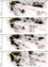 |
Fig. 11 Same as Fig. 9, but for longitudes l = 165, 167.5, 170, and 172.5°. For red dotssee text. |
| In the text | |
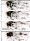 |
Fig. 12 Same as Fig. 9, but for longitudes l = 175, 177.5, 180, and 182.5°. For red dotssee text. |
| In the text | |
Current usage metrics show cumulative count of Article Views (full-text article views including HTML views, PDF and ePub downloads, according to the available data) and Abstracts Views on Vision4Press platform.
Data correspond to usage on the plateform after 2015. The current usage metrics is available 48-96 hours after online publication and is updated daily on week days.
Initial download of the metrics may take a while.