| Issue |
A&A
Volume 593, September 2016
|
|
|---|---|---|
| Article Number | A45 | |
| Number of page(s) | 17 | |
| Section | Interstellar and circumstellar matter | |
| DOI | https://doi.org/10.1051/0004-6361/201528005 | |
| Published online | 12 September 2016 | |
VEGA/CHARA interferometric observations of Cepheids
I. A resolved structure around the prototype classical Cepheid δ Cep in the visible spectral range⋆
1 Université Côte d’Azur, Observatoire
de la Côte d’Azur, CNRS, Laboratoire Lagrange, UMR7293, Nice, France
e-mail: This email address is being protected from spambots. You need JavaScript enabled to view it.
2 European Southern Observatory,
Alonso de Córdova 3107, Casilla
19001, Santiago 19,
Chile
3 Leibniz Institute for Astrophysics,
An der Sternwarte
16, 14482
Potsdam,
Germany
4 Departamento de Astronomía,
Universidad de Concepción, Casilla
160-C, Concepción,
Chile
5 Millenium Institute of Astrophysics,
Santiago,
Chile
6 Observatoire Midi-Pyrénées,
Laboratoire d’Astrophysique, UMR 5572, Université Paul Sabatier – Toulouse 3,
14 avenue Édouard
Belin, 31400
Toulouse,
France
7 Nicolaus Copernicus Astronomical
Center, Polish Academy of Sciences, ul. Bartycka 18, 00-716
Warszawa,
Poland
8 LESIA (UMR 8109), Observatoire de
Paris, PSL, CNRS, UPMC, Univ.
Paris-Diderot, 5 place Jules Janssen, 92195
Meudon,
France
9 Unidad Mixta Internacional
Franco-Chilena de Astronomía, CNRS/INSU, France (UMI 3386) and Departamento de
Astronomía, Universidad de Chile, Camino El Observatorio 1515,
Las Condes, Santiago,
Chile
10 Department of Astronomy & Astrophysics, University of
Toronto, 50 St. George Street, Toronto, ON, M5S 3H4, Canada
11 Laboratoire Dynamique Moléculaire et Matériaux Photoniques,
UR11ES03, Université de Tunis/ESSTT, Tunisie
12 Université de Toulouse, UPS-OMP,
Institut de recherche en Astrophysique et Planétologie, Toulouse,
France
13 CNRS, UMR5277, Institut de
recherche en Astrophysique et Planétologie, 14 avenue Édouard Belin, 31400
Toulouse,
France
14 Université Grenoble Alpes,
IPAG,
38000
Grenoble,
France
15 CNRS, IPAG, 38000
Grenoble,
France
16 INAF–Osservatorio Astronomico di Brera, via E. Bianchi 46,
23807 Merate ( LC), Italy
17 Université de Lyon, Université Lyon
1, École Normale Supérieure de Lyon, CNRS, Centre de Recherche Astrophysique de Lyon
UMR5574, 69230
Saint-Genis-Laval,
France
18 Georgia State University,
PO Box 3969,
Atlanta
GA
30302-3969,
USA
19 CHARA Array, Mount Wilson
Observatory, 91023
Mount Wilson
CA,
USA
Received:
18
December
2015
Accepted:
6
June
2016
Abstract
Context. The B-W method is used to determine the distance of Cepheids and consists in combining the angular size variations of the star, as derived from infrared surface-brightness relations or interferometry, with its linear size variation, as deduced from visible spectroscopy using the projection factor. The underlying assumption is that the photospheres probed in the infrared and in the visible are located at the same layer in the star whatever the pulsation phase. While many Cepheids have been intensively observed by infrared beam combiners, only a few have been observed in the visible.
Aims. This paper is part of a project to observe Cepheids in the visible with interferometry as a counterpart to infrared observations already in hand.
Methods. Observations of δ Cep itself were secured with the VEGA/CHARA instrument over the full pulsation cycle of the star.
Results. These visible interferometric data are consistent in first approximation with a quasi-hydrostatic model of pulsation surrounded by a static circumstellar environment (CSE) with a size of θCSE = 8.9 ± 3.0 mas and a relative flux contribution of fCSE = 0.07 ± 0.01. A model of visible nebula (a background source filling the field of view of the interferometer) with the same relative flux contribution is also consistent with our data at small spatial frequencies. However, in both cases, we find discrepancies in the squared visibilities at high spatial frequencies (maximum 2σ) with two different regimes over the pulsation cycle of the star, φ = 0.0 − 0.8 and φ = 0.8−1.0. We provide several hypotheses to explain these discrepancies, but more observations and theoretical investigations are necessary before a firm conclusion can be drawn.
Conclusions. For the first time we have been able to detect in the visible domain a resolved structure around δ Cep. We have also shown that a simple model cannot explain the observations, and more work will be necessary in the future, both on observations and modelling.
Key words: techniques: interferometric / circumstellar matter / stars: oscillations
The data are available on the Jean-Marie Mariotti Center OiDB service (http://oidb.jmmc.fr) and at the CDS via anonymous ftp to cdsarc.u-strasbg.fr (130.79.128.5) or via http://cdsarc.u-strasbg.fr/viz-bin/qcat?J/A+A/593/A45
© ESO, 2016
1. Introduction
The Baade-Wesselink (BW) method for the distance determination of Cepheids is, in its first version, purely spectro-photometric (Lindemann 1918; Baade 1926; Wesselink 1946). Results by Fouqué et al. (2007) and Storm et al. (2011a,b) illustrate the central and current role of this method in the distance scale calibration, even if recent calibrations of the Hubble constant rely exclusively on the trigonometric parallaxes of a few Galactic Cepheids (Riess et al. 2011; Benedict et al. 2007). The first interferometric version of the BW method was attempted in the visible by Mourard et al. (1997), and soon afterward in the infrared by Kervella et al. (1999, 2001) and Lane et al. (2000). Since then, the infrared interferometric BW method has been applied to a significant number of Cepheids, twelve in total (see Table 1), while among these stars only four have been observed by visible interferometers, and the pulsation could actually be resolved for only one of them, ℓ Car (Davis et al. 2009).
The principle of the interferometric version of the BW method is simple. Interferometric measurements lead to angular diameter estimations over the whole pulsation period, while the stellar radius variations can be deduced from the integration of the pulsation velocity. The latter is linked to the observational velocity deduced from spectral line profiles by the projection factor p (Nardetto et al. 2004; Mérand et al. 2005; Nardetto et al. 2007, 2009).
Cepheids for which an interferometric BW method has been applied.
There are several underlying assumptions to the BW method. First, the limb-darkening of the star is assumed to be constant during the pulsation cycle. This has no impact on the interferometric analysis, at least in the infrared (Kervella et al. 2004), while in the visible Davis et al. (2009) reported the need to take into account a limb-darkening variation from Sydney University Stellar Interferometer (SUSI) observations. On the theoretical side, Nardetto et al. (2006a) found via hydrodynamical simulation that considering a constant limb darkening in the visible leads to a systematic shift of about 0.02 in phase on the angular diameter curve, which basically means that there is no impact on the derived distance (because the amplitude of the angular diameter curve is unchanged). Second, the projection-factor, mostly dominated by the limb-darkening calculated in the visible domain, is also assumed to be constant, which seems reasonable, at least in theory (Nardetto et al. 2004). Third, when applying the BW method, visible spectroscopy (e.g. Nardetto et al. 2006b) is often combined with infrared interferometric data, or even – in the recent photometric version of the BW method – with various photometric bands (Breitfelder et al. 2015). In the distance determination, we implicitly assume that the angular and linear diameters correspond to the same physical layer in the star. In this context, testing these hypotheses using visible interferometric observations seems to be of prime importance. This can be done first by simply verifying the internal consistency of the BW distances derived from visible and infrared interferometry, and then comparing them with available precise parallaxes (Benedict et al. 2007; Majaess et al. 2012).
This paper is the first in a series which investigates Cepheids with the Visible spEctroGraph and polArimeter (VEGA) beam combiner (Mourard et al. 2009) operating at the focus of the Center for High Angular Resolution Astronomy (CHARA) array (ten Brummelaar et al. 2005) located at the Mount Wilson Observatory (California, USA). The study focuses on the prototype δ Cep star. The VEGA data are first reduced (Sect. 2) and then analysed in terms of uniform disk angular diameters (Sect. 3). In Sect. 4, we show that δ Cep is clearly surrounded by a resolved structure, while some evidence in our interferometric data point toward an additional physical effect. We explore two hypotheses: a circumstellar reverberation and a strong limb-darkening variation. We draw our conclusions in Sect. 5.
List and properties of calibration stars selected with the SearchCal software provided by the Jean-Marie Mariotti Center (JMMC) (Bonneau et al. 2006, 2011).
2. VEGA/CHARA observations of δ Cep
The CHARA array consists of six telescopes of 1 m in diameter, spread in a Y-shaped configuration, which offers 15 different baselines from 34 m to 331 m. These baselines can achieve a spatial resolution up to 0.3 mas in the visible. The interferometric observations were secured with the VEGA/CHARA instrument. The journal of observations is presented in Tables A.1 to A.2. Given the large angular size of δ Cep, we used only two short baselines, i.e. S1S2 and E1E2, with projected baselines ranging from about 27 to 31 m for S1S2 and from 52 to 66 m for E1E2. The data were processed using the standard VEGA pipeline (Mourard et al. 2009, 2011; Ligi et al. 2013) considering different spectral bands from 3 nm (in high spectral resolution mode) to 20 nm (in medium spectral resolution mode), and with reference wavelengths ranging from 500 nm to 745 nm (the minimum and maximum wavelengths of these bands are given in Tables A.1 to A.2).
In order to calibrate the squared visibilities, we considered the references stars HD 214734 (C1) and HD 213558 (C2). The first was used to calibrate the data of β Cep presented in Nardetto et al. (2011). Several nights of VEGA observations in 2008 and 2009 were also devoted to controlling the quality of these two calibrators by comparing their transfer functions (defined as the ratio of the actual to expected squared visibility) with those of six other calibrators listed in Table 2 (hereafter C3 to C8). The consistency among the eight calibrators is shown in Fig. A.1, while the general quality of VEGA/CHARA data is illustrated in Fig. A.2.
Cycle-to-cycle variations have never been detected for δ Cep, although they have been for a few other Cepheids (Anderson 2014; Anderson et al. 2016). The data are thus recomposed into a unique cycle and the data corresponding to nights that are close in pulsation phase are merged (see phases 0.180, 0.526, 0.627 in Tables A.1 to A.2). Delta Cephei was finally observed on 20 separate nights corresponding to 17 different pulsation phases. As the observations over a given night can be spread over several hours, we first derive the phase for each observation during the night and then calculate the average and the corresponding standard deviation. The standard deviations of the pulsation phases are rather low and range from 0.001 to 0.017, except for φ = 0.999 where we get an error of 0.025 because the star was observed at the very beginning and at the very end of the night. The pulsation phases can be found in Table 3 together with their respective errors, the number of visibility measurements (N), and the baseline used. For each calibrated visibility, the statistical and systematic calibration errors are given separately. The systematic calibration errors, owing to the uncertainty on the estimation of the diameter of the reference star, were found to be negligible compared to the statistical values. Therefore, we only considered the statistical uncertainties in the model fitting. In a few cases, the statistical uncertainty was clearly underestimated. Thus, we fixed the uncertainty on the calibrated squared visibility to 0.05 (Mourard et al. 2012) for the following nights: 2012 September 23, 2013 October 26, 2013 November 26, 2014 July 02, 2014 July 05, and 2014 July 09.
Pulsation phases, number of visibility measurements (N), resulting uniform disk angular diameters, and reduced χ2.
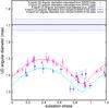 |
Fig. 1 Uniform disk diameters θUD derived from the VEGA/CHARA E1E2 data plotted as a function of the pulsation phase (blue crosses). The S1S2 data (corresponding to four different pulsation phases, see Table 3) were merged and the corresponding mean θUD is represented by a black horizontal line together with the 1σ uncertainty (blue dashed zone). The uniform disk angular diameter curve from FLUOR/CHARA in the K band (Mérand et al. 2005) is also shown for comparison. The red crosses and the light blue squares show the K band and R band UD angular diameter curves, respectively, as predicted from the SPIPS code (Merand et al. 2015a). |
3. Uniform disk (UD) angular diameters
In Figs. A.3, the calibrated visibilities corresponding to E1E2 measurements are plotted as a function of the spatial frequency together with the corresponding (u,v) coverage and for each pulsation phase. We fit these calibrated visibilities by a uniform disk using a JMMC1 tool, LITpro (Tallon-Bosc et al. 2008). The results are given in Table 3 and plotted in Fig. 1 with blue crosses. The data corresponding to S1S2 measurements are shown in Fig. 2a. Owing to their low spatial frequencies, these S1S2 measurements are almost not sensitive to the pulsation of the star. This can be seen in Fig. 2b. Moreover, we have only a few S1S2 measurements per pulsation phase (four at most). Consequently, as a point of comparison with the E1E2 data, we merge the S1S2 data and fit them with a uniform disk angular diameter. The result is given in Table 3 and plotted in Fig. 1 by a horizontal dashed zone. For the data of 2014 October 24, which include both E1E2 and S1S2 baselines, we made two fits, one including all the S1S2 data and another with the E1E2 data. We overplot the very precise K-band uniform disk angular diameter curve obtained by Mérand et al. (2005) (magenta dots). To analyse our VEGA/CHARA angular diameter measurements, we consider the Spectroscopy-Photometry-Interferometry for Pulsating Stars algorithm (SPIPS; Merand et al. 2015a). The SPIPS code combines all the available observables of δ Cep: radial velocimetry (Bersier et al. 1994; Storm et al. 2004), interferometry (FLUOR/CHARA data), and photometry in the V (Berdnikov & Turner 2002; Engle et al. 2014; Kiss 1998; Moffett & Barnes 1984), J, H, and K bands (Barnes et al. 1997) in order to estimate the projection factor, the variation of the effective temperature, and the H and K band excesses. The data used for the fit for δ Cep have been published in digital form (Merand et al. 2015b). In the list of these outputs, we are particularly interested in the uniform disk angular diameter curves, calculated at 2200 nm and 800 nm, and derived directly from the framework of Merand et al. (2015a). The data are given in Table 4 and are shown in Fig. 1 by red crosses and light blue squares, respectively. In the infrared, the K-band UD angular diameter curve of SPIPS is consistent with the FLUOR/CHARA measurements. In the visible domain, the reduced χ2 between the VEGA (E1E2) and SPIPS UD angular diameters is 9, while it increases slightly to 11 when we replace the SPIPS angular diameter variation by a constant corresponding to the average of the VEGA UD angular diameters, i.e. 1.376 ± 0.030 mas. We thus detect a pulsation in the visible band, but make three remarks:
Angular diameters as derived from the application of the SPIPS algorithm to δ Cep, using photometry, interferometry, and the cross-correlated radial velocity curves as inputs (see Merand et al. 2015a).
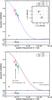 |
Fig. 2 a) S1S2 observed calibrated squared visibilities secured at four different pulsation phases plotted as a function of the spatial frequency together with the best fit of uniform disk model (solid blue line). In the upper right corner we show the corresponding (u,v) coverage. b) Same data fitted with a two-component model (open symbols) including a uniform pulsating disk and a CSE (see text). As a comparison, the solid lines are the corresponding one-component models, i.e. a uniform pulsating disk (in the R band) without the CSE. |
-
1.
The VEGA S1S2 measurements provide a mean θUD (with a reduced χ2 of 0.9), which is significantly larger than the E1E2 angular diameter curve by about 10σ. This suggests the presence of a large angular structure around the pulsating Cepheid.
-
2.
The SPIPS predictions are consistent with the VEGA θUD angular diameters from 0.0 to 0.8 in phase (with a reduced χ2 of 4). This basically means that δ Cep is pulsating in a quasi-hydrostatic way over this range of pulsation phase, even if the two measurements (at φ = 0.741 and φ = 0.783) are slightly below the SPIPS curve (around 2σ).
-
3.
Five measurements between 0.8 and 1.0 are clearly from 2 to 6σ above the SPIPS curve (with a reduced χ2 of 8).
4. Detection of a circumstellar environment or a nebulae in the visible
In Fig. 2b, the S1S2 data are fitted with a model (open symbols) composed of the UD derived from the SPIPS UD angular diameter curve at the corresponding phases of VEGA observations and a second static disk describing the circumstellar environment (CSE). The orientation of the S1S2 measurements in the (u,v) coverage are between 148 and 171 degrees, preventing us from investigating a non-centrosymmetric CSE. The best-fit parameters are θCSE = 8.9 ± 3.0 mas (the size of the CSE) and  (the relative flux contribution of the CSE, where fcse and f⋆ are the fluxes of the CSE and the star in the R band, respectively) with a reduced χ2 of 0.6. The two parameters, however, are significantly correlated (0.8) owing to the low number of S1S2 observations. Interestingly, we can also fit the S1S2 data (with the same reduced χ2 of 0.6) using a model composed of a pulsating disk, as in the previous case, together with a background contribution of 0.07 ± 0.01 in flux filling the field of view of the interferometer. This model physically corresponds to the visible counterpart of the infrared nebulae discovered by Marengo et al. (2010) and the HI nebula found with the Very Large Array (VLA) (Matthews et al. 2012). Unfortunately, our S1S2 data are too scarce to distinguish between these two hypotheses.
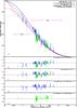 |
Fig. 3 Panel a), the VEGA squared visibilities plotted as a function of |
![Mathematical equation: \hbox{$x = \frac{\pi B_{\rm p} \mathrm{[m]} \theta_\mathrm{UD} \mathrm{[mas]} }{\lambda \mathrm{[nm]}}$}](/articles/aa/full_html/2016/09/aa28005-15/aa28005-15-eq74.png)
We have fitted the S1S2 data with a two-component model without considering the E1E2 data. Hence, we now have to verify whether this two-component model is consistent with our E1E2 data, in particular at minimum radius. In Sect. 3, we find that the E1E2 measurements are not consistent with a quasi-hydrostatic pulsating disk at the minimum radius of the star (between phase 0.8 and 1.0).
In order to address this issue, we plot in panel a) of Fig. 3 all the VEGA visibilities measured as a function of ![Mathematical equation: \hbox{$x=\frac{\pi B_{\rm p} \mathrm{[m]} \theta_\mathrm{UD} \mathrm{[mas]}}{\lambda \mathrm{[nm]}}$}](/articles/aa/full_html/2016/09/aa28005-15/aa28005-15-eq75.png) , where θUD is fixed and interpolated from the SPIPS UD angular diameter curve at the corresponding pulsation phase of VEGA observations. The data are rescaled in such a way that they can be compared, despite different θUD (or pulsation phases) and different wavelengths of observation. This is possible since the reference is the SPIPS θUD semi-theoretical curve represented by the solid blue line expressed by
, where θUD is fixed and interpolated from the SPIPS UD angular diameter curve at the corresponding pulsation phase of VEGA observations. The data are rescaled in such a way that they can be compared, despite different θUD (or pulsation phases) and different wavelengths of observation. This is possible since the reference is the SPIPS θUD semi-theoretical curve represented by the solid blue line expressed by  , where J1 is the Bessel function of the first order. This concept of pseudo-baseline was first introduced by Mérand et al. (2006). Using this approach, we confirm the three statements found in Sect. 3:
-
1.
The S1S2 measurements, whatever the pulsation phase, are significantly lower than in the rescaled uniform disk model (see the S1S2 measurements, i.e. data with x from approximately 0.5 to 1.4, Fig. 3b). This deviation is removed as soon as we consider a resolved structure around δ Cep (see below).
-
2.
The data with a pulsating phase from φ = 0.0 to φ = 0.8 are consistent with the uniform disk model for E1E2 measurements (blue crosses with x from 1.5 to 2.8 in Fig. 3b).
-
3.
The data with a pulsating phase from φ = 0.8 to φ = 1.0 are not consistent with the uniform disk model for E1E2 measurements (green circles around x = 1.7 in Fig. 3b).
 (1)where fcse = 0.065 and f⋆ = 0.935 (corresponding to and fcse + f⋆ = 1), sr is the mean size ratio between the CSE and the pulsating disk. Considering the mean UD angular diameter of the SPIPS curve (θmean = 1.39 mas), we find sr = 6.32. The result is unchanged (i.e. within the width of the line) if we use the 6.75 and 6.07 values corresponding to the minimum and maximum UD angular diameters.
We find that the S1S2 measurements are properly fitted by this two-component model, as expected (Fig. 3c). However, around x = 1.7 the E1E2 measurements corresponding to φ = 0.0−0.8 and φ = 0.8−1.0 are respectively above and below the curve (by about 2σ). All the E1E2 measurements are partly above the curve (about 1σ) at larger frequencies (x> 2.3).
If we consider the model composed of a uniform disk surrounded by a background, we obtain 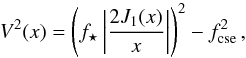 (2)and the corresponding curve is plotted by a magenta dotted line in Fig. 3a. We arrive at the same conclusions as the model of the pulsating uniform disk surrounded by a CSE. In particular, we find the presence of two regimes in phase, even considering a CSE or a background. We explore two hypotheses.
First, we cannot fit all the VEGA measurements at the same time if we consider a CSE two times fainter or brighter (see black dotted and dot-dashed lines in Fig. 3a). Qualitatively, however, it seems that considering a CSE two times fainter between phase 0.0 and 0.8 is a good compromise to fit the S1S2 and E1E2 measurements together, even if not totally satisfactory (see Fig. 3d). To consider a CSE two times brighter between phase 0.8 and 1.0 (when the size of the star is at a minimum, and is hot and bright) helps to fit the data except at large spatial frequencies (see Fig. 3e). If this hypothesis is correct, then the δ Cep would light up its environment (CSE or background) differently at maximum and minimum radius.
The second possibility is to consider that the CSE (or the background) has a constant brightness and that the discrepancy found for E1E2 measurements comes mainly from an additional structure angularly smaller (φ = 0.0−0.8) or larger (φ = 0.8−1.0) in size than the SPIPS θUD stellar pulsating disk, for instance a strong limb-darkening variation. The limb-darkening coefficient, defined as  , is used to convert the θUD diameters into limb-darkened θLD angular diameters. The k coefficient variation in the visible band (at 600 nm) and over the cycle of pulsation of the star is found to be from the hydrodynamical model of 0.015 (Nardetto et al. 2006a), which corresponds to about 1%. Similarly, Marengo et al. (2002, 2003) have found a variation for the k-parameter of about 0.01 and 0.02 for ζ Gem and at 570 nm using quasi-hydrostatic and hydrodynamical models, respectively. Also for comparison, Davis et al. (2009) used a phase-dependent k-parameter to analyse their SUSI data of ℓ Car, and found a variation of 0.012. This means typically a 1% difference in θUD, and thus a 1% difference in x, which corresponds to 0.02 in absolute value around x = 1.7 in Fig. 3. Consequently, the limb-darkening variation of δ Cep is one order of magnitude lower than the discrepancies found for the E1E2 measurements. In the case of δ Cep, the theoretical average value of k is of 0.954 (Nardetto et al. 2006a). So far, the only published direct measurement of the limb-darkening coefficient of a Cepheid (in the visible) has been performed by Pilecki et al. (2013) for a Cepheid (P = 3.80 d) in an eclipsing binary system in the LMC. They find the limb-darkening effect to be much stronger than expected for a star of that temperature, giving a possible range for k from 0.91 to 0.93, assuming however no temperature dependence. Recently, Gieren et al. (2015) studied another Cepheid in the LMC (P = 2.99 d) and found a similar rather strong limb-darkening effect. If we consider the lower k value found by Pilecki et al. (2013), all the E1E2 measurements in Fig. 3 should translate towards lower values of x − 4% or about 0.06. The measurements in blue crosses in the figure would be better fitted, while green open circles would not (in particular near x ≃ 1.7). The limb-darkening effect is probably not the key issue to explain the discrepancy found for the E1E2 measurements.
5. Discussion
We observed δ Cep intensively on twenty nights. The initial purpose of these observations was to apply the BW method, but instead we detected for the very first time a static resolved structure around δ Cep contributing to about 7% of the total flux in the visible. This is not totally surprising as envelopes around Cepheids have already been discovered by long-baseline interferometry in the K band with VLTI and CHARA (Kervella et al. 2006; Mérand et al. 2006). In addition, four Cepheids have also been observed in the N band with VISIR and MIDI (Kervella et al. 2009; Gallenne et al. 2013) and one with NACO (Gallenne et al. 2011, 2012). Some evidence has also been found using high-resolution spectroscopy (Nardetto et al. 2008). From these observations, the typical size of the envelope of Cepheids seems to be around 3 stellar radii and the flux contribution from 2% to 10% of the continuum in the K band for medium- and long-period Cepheids, respectively, while it is around 10% or more in the N band. However, Mérand et al. (2005) do not mention any contribution from a CSE in the case of δ Cep in their infrared FLUOR data, while Mérand et al. (2006) found an improved agreement with a larger set of data when considering a model with a CSE. They used a ring model 3.54 mas in size, 0.5 mas in width, and with a relative brightness of 1.5%, which is confirmed in Merand et al. (2015a). The processes at work in infrared and in the visible regarding the CSE are different. We expect thermal emission in the infrared and scattering in the visible. It is also worth mentioning that the mid-infrared flux in excess is not necessarily the evidence for mass loss (see e.g. Schmidt 2015) and that the resolved structure we observe around δ Cep, instead of a CSE, could be simply a visible nebulae (also contributing to 7% of the total flux), as reported in the infrared by Marengo et al. (2010) and in the radio domain by Matthews et al. (2012).
Our second result is the presence of an additional second-order discrepancy between the observations and the models (pulsating disk + CSE or pulsating disk + background) at high spatial frequencies, which is not clearly understood. One possibility could be that the star is lighting up its environment differently at minimum (φ ≃ 0.8−1.0) and maximum (φ ≃ 0.0−0.8) radius. This reverberation effect would then be more important in the visible than in the infrared since the contribution in flux of the CSE (or the background) in the visible band is about 7% compared to 1.5% in the infrared. Interestingly, the phase interval from 0.8 to 1.0 is usually disregarded in the infrared surface brightness version of the BW method owing to general poor agreement between spectroscopic and photometric angular diameters (Storm et al. 2011a,b). The other possibility is to consider a static environment with a constant brightness in time, but with an additional dynamical effect. However, from the hydrodynamical simulations and observations of Cepheids in eclipsing binary systems, it seems that the limb-darkening effect in the visible band does not vary strongly enough to reproduce the second-order discrepancy found in our interferometric observations. Also possible is a strong compression or shockwave occurring near the photosphere at the minimum radius, which is indeed the layer probed by photometry and interferometry. However, such a shock is not seen in the hydrodynamical code (Nardetto et al. 2004) or in the spectroscopic data, conversely to X Sgr, an atypical Cepheid in which a shockwave has indeed been reported (Mathias et al. 2006). Why this dynamical effect is seen in the visible band and not in the infrared is another pending question in this hypothesis. We also exclude non-radial pulsation, since very accurate space photometry does not support the detection of such modes in Galactic classical Cepheids (e.g. Poretti et al. 2015), and the previous spectroscopic campaigns would have shown up quite easily. Furthermore, Anderson et al. (2015) found the signature of a companion in recent spectroscopic data of δ Cep. The expected flux contribution is supposed to be lower than 1% in the visible, clearly not detectable by VEGA/CHARA. Finally, reverberation seems to be the more plausible hypothesis. More interferometric data on Cepheids in the visible might shed light on it. In particular, covering the spatial frequencies properly (x from 0.2 to 3) at a unique pulsating phase (maximum and minimum radii) is probably required to go further in the analysis.
Acknowledgments
The authors acknowledge the support of the French Agence Nationale de la Recherche (ANR), under grant ANR-15-CE31-0012- 01 (project UnlockCepheids). We acknowledge financial support from “Programme National de Physique Stellaire” (PNPS) of CNRS/INSU, France. The CHARA Array is funded by the National Science Foundation through NSF grants AST-0606958 and AST-0908253 and by Georgia State University through the College of Arts and Sciences, as well as the W. M. Keck Foundation. W.G. gratefully acknowledges financial support for this work from the BASAL Centro de Astrofisica y Tecnologias Afines (CATA) PFB-06/2007, and from the Millenium Institute of Astrophysics (MAS) of the Iniciativa Cientifica Milenio del Ministerio de Economia, Fomento y Turismo de Chile, project IC120009. We acknowledge financial support for this work from ECOS-CONICYT grant C13U01. Support from the Polish National Science Center grant MAESTRO 2012/06/A/ST9/00269 is also acknowledged. EP and MR acknowledge financial support from PRIN INAF-2014. N.N., P.K., A.G., and W.G. acknowledge support from the French-Chilean exchange program ECOS- Sud/CONICYT (C13U01). This project was partially supported by the Polish Ministry of Science grant Ideas Plus. This research has made use of the SIMBAD and VIZIER databases at CDS, Strasbourg, France (http://cdsweb.u- strasbg.fr/), the Jean-Marie Mariotti Center Aspro service (http://www.jmmc.fr/aspro), and the electronic bibliography maintained by the NASA/ADS system. This research has made use of the Jean-Marie Mariotti Center SearchCal service (http://www.jmmc.fr/searchcal) co-developed by FIZEAU and LAOG/IPAG, and CDS Astronomical Databases SIMBAD and VIZIER (http://cdsweb.u-strasbg.fr/). This research has made use of the Jean-Marie Mariotti Center LITpro service co-developed by CRAL, IPAG, and LAGRANGE (LITpro software available at http://www.jmmc.fr/litpro). This research has made use of the Jean-Marie Mariotti Center OiDB service (http://oidb.jmmc.fr).
References
- Anderson, R. I. 2014, A&A, 566, L10 [NASA ADS] [CrossRef] [EDP Sciences] [Google Scholar]
- Anderson, R. I., Sahlmann, J., Holl, B., et al. 2015, ApJ, 804, 144 [NASA ADS] [CrossRef] [Google Scholar]
- Anderson, R. I., Mérand, A., Kervella, P., et al. 2016, MNRAS, 455, 4231 [NASA ADS] [CrossRef] [Google Scholar]
- Armstrong, J. T., Nordgren, T. E., Germain, M. E., et al. 2001, AJ, 121, 476 [NASA ADS] [CrossRef] [Google Scholar]
- Baade, W. 1926, Astron. Nachr., 228, 359 [NASA ADS] [CrossRef] [Google Scholar]
- Barnes, III, T. G., Fernley, J. A., Frueh, M. L., et al. 1997, PASP, 109, 645 [NASA ADS] [CrossRef] [Google Scholar]
- Benedict, G. F., McArthur, B. E., Fredrick, L. W., et al. 2002, AJ, 124, 1695 [NASA ADS] [CrossRef] [Google Scholar]
- Benedict, G. F., McArthur, B. E., Feast, M. W., et al. 2007, AJ, 133, 1810 [NASA ADS] [CrossRef] [Google Scholar]
- Berdnikov, L. N., & Turner, D. G. 2002, VizieR Online Data Catalog J/ApJS/137/209 [Google Scholar]
- Bersier, D., Burki, G., Mayor, M., & Duquennoy, A. 1994, A&AS, 108, 25 [NASA ADS] [Google Scholar]
- Bonneau, D., Clausse, J.-M., Delfosse, X., et al. 2006, A&A, 456, 789 [NASA ADS] [CrossRef] [EDP Sciences] [Google Scholar]
- Bonneau, D., Delfosse, X., Mourard, D., et al. 2011, A&A, 535, A53 [NASA ADS] [CrossRef] [EDP Sciences] [Google Scholar]
- Breitfelder, J., Kervella, P., Mérand, A., et al. 2015, A&A, 576, A64 [NASA ADS] [CrossRef] [EDP Sciences] [Google Scholar]
- Breitfelder, J., Mérand, A., Kervella, P., et al. 2016, A&A, 587, A117 [NASA ADS] [CrossRef] [EDP Sciences] [Google Scholar]
- Davis, J., Jacob, A. P., Robertson, J. G., et al. 2009, MNRAS, 394, 1620 [NASA ADS] [CrossRef] [Google Scholar]
- Engle, S. G., Guinan, E. F., Harper, G. M., Neilson, H. R., & Remage Evans, N. 2014, ApJ, 794, 80 [NASA ADS] [CrossRef] [Google Scholar]
- Fouqué, P., Arriagada, P., Storm, J., et al. 2007, A&A, 476, 73 [NASA ADS] [CrossRef] [EDP Sciences] [Google Scholar]
- Gallenne, A., Mérand, A., Kervella, P., & Girard, J. H. V. 2011, A&A, 527, A51 [Google Scholar]
- Gallenne, A., Kervella, P., & Mérand, A. 2012, A&A, 538, A24 [NASA ADS] [CrossRef] [EDP Sciences] [Google Scholar]
- Gallenne, A., Mérand, A., Kervella, P., et al. 2013, A&A, 558, A140 [NASA ADS] [CrossRef] [EDP Sciences] [Google Scholar]
- Gieren, W., Pilecki, B., Pietrzyński, G., et al. 2015, ApJ, 815, 28 [NASA ADS] [CrossRef] [Google Scholar]
- Kervella, P., Coudé du Foresto, V., Traub, W. A., & Lacasse, M. G. 1999, in Working on the Fringe: Optical and IR Interferometry from Ground and Space, eds. S. Unwin, & R. Stachnik, ASP Conf. Ser., 194, 22 [Google Scholar]
- Kervella, P., Coudé du Foresto, V., Perrin, G., et al. 2001, A&A, 367, 876 [NASA ADS] [CrossRef] [EDP Sciences] [Google Scholar]
- Kervella, P., Nardetto, N., Bersier, D., Mourard, D., & Coudé du Foresto, V. 2004, A&A, 416, 941 [NASA ADS] [CrossRef] [EDP Sciences] [Google Scholar]
- Kervella, P., Mérand, A., Perrin, G., & Coudé du Foresto, V. 2006, A&A, 448, 623 [NASA ADS] [CrossRef] [EDP Sciences] [Google Scholar]
- Kervella, P., Mérand, A., & Gallenne, A. 2009, A&A, 498, 425 [NASA ADS] [CrossRef] [EDP Sciences] [Google Scholar]
- Kiss, L. L. 1998, in A Half Century of Stellar Pulsation Interpretation, eds. P. A. Bradley, & J. A. Guzik, ASP Conf. Ser., 135, 173 [Google Scholar]
- Kukarkin, B. V., Kholopov, P. N., Pskovsky, Y. P., et al. 1971, in General Catalogue of Variable Stars, 3rd edn. [Google Scholar]
- Lafrasse, S., Mella, G., Bonneau, D., et al. 2010, VizieR Online Data Catalog: II/300 [Google Scholar]
- Lane, B. F., Kuchner, M. J., Boden, A. F., Creech-Eakman, M., & Kulkarni, S. R. 2000, Nature, 407, 485 [NASA ADS] [CrossRef] [Google Scholar]
- Lane, B. F., Creech-Eakman, M. J., & Nordgren, T. E. 2002, ApJ, 573, 330 [NASA ADS] [CrossRef] [Google Scholar]
- Ligi, R., Mourard, D., Nardetto, N., & Clausse, J.-M. 2013, J. Astron. Instrum., 2, 40003 [Google Scholar]
- Lindemann, F. A. 1918, MNRAS, 78, 639 [NASA ADS] [CrossRef] [Google Scholar]
- Majaess, D., Turner, D., & Gieren, W. 2012, ApJ, 747, 145 [NASA ADS] [CrossRef] [Google Scholar]
- Marengo, M., Sasselov, D. D., Karovska, M., Papaliolios, C., & Armstrong, J. T. 2002, ApJ, 567, 1131 [NASA ADS] [CrossRef] [Google Scholar]
- Marengo, M., Karovska, M., Sasselov, D. D., et al. 2003, ApJ, 589, 968 [NASA ADS] [CrossRef] [Google Scholar]
- Marengo, M., Evans, N. R., Barmby, P., et al. 2010, ApJ, 725, 2392 [NASA ADS] [CrossRef] [Google Scholar]
- Mathias, P., Gillet, D., Fokin, A. B., et al. 2006, A&A, 457, 575 [NASA ADS] [CrossRef] [EDP Sciences] [Google Scholar]
- Matthews, L. D., Marengo, M., Evans, N. R., & Bono, G. 2012, ApJ, 744, 53 [NASA ADS] [CrossRef] [Google Scholar]
- Mérand, A., Kervella, P., Coudé du Foresto, V., et al. 2005, A&A, 438, L9 [Google Scholar]
- Mérand, A., Kervella, P., Coudé du Foresto, V., et al. 2006, A&A, 453, 155 [NASA ADS] [CrossRef] [EDP Sciences] [Google Scholar]
- Mérand, A., Aufdenberg, J. P., Kervella, P., et al. 2007, ApJ, 664, 1093 [NASA ADS] [CrossRef] [Google Scholar]
- Merand, A., Kervella, P., Breitfelder, J., et al. 2015a, A&A, 584, A80 [NASA ADS] [CrossRef] [EDP Sciences] [Google Scholar]
- Merand, A., Kervella, P., Breitfelder, J., et al. 2015b, VizieR Online Data Catalog: J/A+A/584/A80 [Google Scholar]
- Moffett, T. J., & Barnes, III, T. G. 1984, ApJS, 55, 389 [NASA ADS] [CrossRef] [Google Scholar]
- Mourard, D., Bonneau, D., Koechlin, L., et al. 1997, A&A, 317, 789 [Google Scholar]
- Mourard, D., Clausse, J. M., Marcotto, A., et al. 2009, A&A, 508, 1073 [NASA ADS] [CrossRef] [EDP Sciences] [Google Scholar]
- Mourard, D., Bério, P., Perraut, K., et al. 2011, A&A, 531, A110 [NASA ADS] [CrossRef] [EDP Sciences] [Google Scholar]
- Mourard, D., Challouf, M., Ligi, R., et al. 2012, in SPIE Conf. Ser., 8445, 0 [Google Scholar]
- Nardetto, N., Fokin, A., Mourard, D., et al. 2004, A&A, 428, 131 [NASA ADS] [CrossRef] [EDP Sciences] [Google Scholar]
- Nardetto, N., Fokin, A., Mourard, D., & Mathias, P. 2006a, A&A, 454, 327 [Google Scholar]
- Nardetto, N., Mourard, D., Kervella, P., et al. 2006b, A&A, 453, 309 [NASA ADS] [CrossRef] [EDP Sciences] [Google Scholar]
- Nardetto, N., Mourard, D., Mathias, P., Fokin, A., & Gillet, D. 2007, A&A, 471, 661 [NASA ADS] [CrossRef] [EDP Sciences] [Google Scholar]
- Nardetto, N., Groh, J. H., Kraus, S., Millour, F., & Gillet, D. 2008, A&A, 489, 1263 [NASA ADS] [CrossRef] [EDP Sciences] [Google Scholar]
- Nardetto, N., Gieren, W., Kervella, P., et al. 2009, A&A, 502, 951 [NASA ADS] [CrossRef] [EDP Sciences] [Google Scholar]
- Nardetto, N., Mourard, D., Tallon-Bosc, I., et al. 2011, A&A, 525, A67 [NASA ADS] [CrossRef] [EDP Sciences] [Google Scholar]
- Nordgren, T. E., Armstrong, J. T., Germain, M. E., et al. 2000, ApJ, 543, 972 [NASA ADS] [CrossRef] [Google Scholar]
- Pilecki, B., Graczyk, D., Pietrzyński, G., et al. 2013, MNRAS, 436, 953 [NASA ADS] [CrossRef] [Google Scholar]
- Poretti, E., Le Borgne, J. F., Rainer, M., et al. 2015, MNRAS, 454, 849 [NASA ADS] [CrossRef] [Google Scholar]
- Riess, A. G., Macri, L., Casertano, S., et al. 2011, ApJ, 730, 119 [NASA ADS] [CrossRef] [Google Scholar]
- Schmidt, E. G. 2015, ApJ, 813, 29 [NASA ADS] [CrossRef] [Google Scholar]
- Storm, J., Carney, B. W., Gieren, W. P., et al. 2004, A&A, 415, 531 [NASA ADS] [CrossRef] [EDP Sciences] [Google Scholar]
- Storm, J., Gieren, W., Fouqué, P., et al. 2011a, A&A, 534, A94 [NASA ADS] [CrossRef] [EDP Sciences] [Google Scholar]
- Storm, J., Gieren, W., Fouqué, P., et al. 2011b, A&A, 534, A95 [NASA ADS] [CrossRef] [EDP Sciences] [Google Scholar]
- Tallon-Bosc, I., Tallon, M., Thiébaut, E., et al. 2008, in SPIE Conf. Ser., 7013 [Google Scholar]
- ten Brummelaar, T. A., McAlister, H. A., Ridgway, S. T., et al. 2005, ApJ, 628, 453 [NASA ADS] [CrossRef] [Google Scholar]
- Wesselink, A. J. 1946, Bull. Astron. Inst. Netherlands, 10, 91 [Google Scholar]
Appendix A: VEGA observations: Log, transfer functions, and visibility curves
Observing log with the E1E2 baseline.
Observing log with the S1S2 baseline.
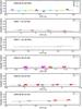 |
Fig. A.1 Two calibrators, C1 and C2, used to calibrate the VEGA/CHARA data of δ Cep are compared in terms of transfer functions with six other calibrators, C3 to C8 (listed in Table 2), on six different nights during 2008 and 2009. The consistency between the calibrators, which is shown by a linear fit (black line), is independent of the two-telescope baseline considered, S1S2 or W1W2. |
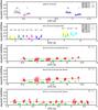 |
Fig. A.2 Transfer function (calculated either from the C1 or C2 calibrator) is shown together with the raw visibilities of the target (T) for four different nights in our sample, using different spectral configurations and two baselines, E1E2 and S1S2. For nights 2008 July 30 and 2014 October 24, the squared visibilities (or transfer functions) associated with calibrators C1 and C2 cannot be consistently compared as they correspond to different spectral configurations, but they are shown to illustrate the quality of the data. The 2014 October 24 observing night is the only one for which we have successive data from E1E2 (from around 3.5h to 6h in UTC) and S1S2 (from around 6.5h to 8h in UTC). For nights 2013 July 25 and 2013 December 17, the instrument configuration is the same over the entire observing time, and the stability of the transfer function is evident (black line). |
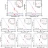 |
Fig. A.3 Observed calibrated squared visibilities (red dots) are plotted as a function of the spatial frequency for each pulsation phase (indicated in the lower left corner of each panel) together with the best fit of uniform disk model (solid blue line). In the upper right corner (inset panel) we show the corresponding (u,v) coverage. |
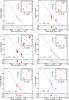 |
Fig. A.3 continued. |
All Tables
List and properties of calibration stars selected with the SearchCal software provided by the Jean-Marie Mariotti Center (JMMC) (Bonneau et al. 2006, 2011).
Pulsation phases, number of visibility measurements (N), resulting uniform disk angular diameters, and reduced χ2.
Angular diameters as derived from the application of the SPIPS algorithm to δ Cep, using photometry, interferometry, and the cross-correlated radial velocity curves as inputs (see Merand et al. 2015a).
All Figures
|
Fig. 1 Uniform disk diameters θUD derived from the VEGA/CHARA E1E2 data plotted as a function of the pulsation phase (blue crosses). The S1S2 data (corresponding to four different pulsation phases, see Table 3) were merged and the corresponding mean θUD is represented by a black horizontal line together with the 1σ uncertainty (blue dashed zone). The uniform disk angular diameter curve from FLUOR/CHARA in the K band (Mérand et al. 2005) is also shown for comparison. The red crosses and the light blue squares show the K band and R band UD angular diameter curves, respectively, as predicted from the SPIPS code (Merand et al. 2015a). |
| In the text | |
|
Fig. 2 a) S1S2 observed calibrated squared visibilities secured at four different pulsation phases plotted as a function of the spatial frequency together with the best fit of uniform disk model (solid blue line). In the upper right corner we show the corresponding (u,v) coverage. b) Same data fitted with a two-component model (open symbols) including a uniform pulsating disk and a CSE (see text). As a comparison, the solid lines are the corresponding one-component models, i.e. a uniform pulsating disk (in the R band) without the CSE. |
| In the text | |
|
Fig. 3 Panel a), the VEGA squared visibilities plotted as a function of |
| In the text | |
|
Fig. A.1 Two calibrators, C1 and C2, used to calibrate the VEGA/CHARA data of δ Cep are compared in terms of transfer functions with six other calibrators, C3 to C8 (listed in Table 2), on six different nights during 2008 and 2009. The consistency between the calibrators, which is shown by a linear fit (black line), is independent of the two-telescope baseline considered, S1S2 or W1W2. |
| In the text | |
|
Fig. A.2 Transfer function (calculated either from the C1 or C2 calibrator) is shown together with the raw visibilities of the target (T) for four different nights in our sample, using different spectral configurations and two baselines, E1E2 and S1S2. For nights 2008 July 30 and 2014 October 24, the squared visibilities (or transfer functions) associated with calibrators C1 and C2 cannot be consistently compared as they correspond to different spectral configurations, but they are shown to illustrate the quality of the data. The 2014 October 24 observing night is the only one for which we have successive data from E1E2 (from around 3.5h to 6h in UTC) and S1S2 (from around 6.5h to 8h in UTC). For nights 2013 July 25 and 2013 December 17, the instrument configuration is the same over the entire observing time, and the stability of the transfer function is evident (black line). |
| In the text | |
|
Fig. A.3 Observed calibrated squared visibilities (red dots) are plotted as a function of the spatial frequency for each pulsation phase (indicated in the lower left corner of each panel) together with the best fit of uniform disk model (solid blue line). In the upper right corner (inset panel) we show the corresponding (u,v) coverage. |
| In the text | |
|
Fig. A.3 continued. |
| In the text | |
Current usage metrics show cumulative count of Article Views (full-text article views including HTML views, PDF and ePub downloads, according to the available data) and Abstracts Views on Vision4Press platform.
Data correspond to usage on the plateform after 2015. The current usage metrics is available 48-96 hours after online publication and is updated daily on week days.
Initial download of the metrics may take a while.