| Issue |
A&A
Volume 588, April 2016
|
|
|---|---|---|
| Article Number | A106 | |
| Number of page(s) | 9 | |
| Section | Interstellar and circumstellar matter | |
| DOI | https://doi.org/10.1051/0004-6361/201527988 | |
| Published online | 25 March 2016 | |
The extinction and dust-to-gas structure of the planetary nebula NGC 7009 observed with MUSE⋆
1 European Southern Observatory. Karl-Schwarzschild Strasse 2, 85748 Garching, Germany
e-mail: This email address is being protected from spambots. You need JavaScript enabled to view it.
2 GEPI, Observatoire de Paris, PSL Research University, CNRS, Université Paris-Diderot, Sorbonne Paris Cité, Place Jules Janssen, 92195 Meudon, France
3 Dept. of Physics and Astronomy, University College London, Gower Street, London WC1E 6BT, UK
4 Department of Physics and Astronomy, University of Denver, 2112 E. Wesley Ave., Denver, CO 80210, USA
5 European Southern Observatory, Alonso de Córdova 3107, Casilla 19001, Santiago, Chile
6 Jodrell Bank Centre for Astrophysics, Alan Turing Building, University of Manchester, Manchester M13 9PL, UK
Received: 17 December 2015
Accepted: 17 February 2016
Abstract
Context. Dust plays a significant role in planetary nebulae. Dust ejected with the gas in the asymptotic giant branch (AGB) phase is subject to the harsh environment of the planetary nebula (PN) while the star is evolving towards a white dwarf. Dust surviving the PN phase contributes to the dust content of the interstellar medium.
Aims. The morphology of the internal dust extinction has been mapped for the first time in a PN, the bright nearby Galactic nebula NGC 7009. The morphologies of the gas, dust extinction and dust-to-gas ratio are compared to the structural features of the nebula.
Methods. Emission line maps in H Balmer and Paschen lines were formed from analysis of MUSE cubes of NGC 7009 observed during science verification of the instrument. The measured electron temperature and density from the same cube were employed to predict the theoretical H line ratios and derive the extinction distribution across the nebula. After correction for the interstellar extinction to NGC 7009, the internal AV/NH has been mapped for the first time in a PN.
Results. The extinction map of NGC 7009 has considerable structure, broadly corresponding to the morphological features of the nebula. The dust-to-gas ratio, AV/NH, increases from 0.7 times the interstellar value to >5 times from the centre towards the periphery of the ionized nebula. The integrated AV/NH is about 2× the mean ISM value. A large-scale feature in the extinction map is a wave, consisting of a crest and trough, at the rim of the inner shell. The nature of this feature is investigated and instrumental and physical causes considered; no convincing mechanisms were identified to produce this feature, other than AGB mass loss variations.
Conclusions. Extinction mapping from H emission line imaging of PNe with MUSE provides a powerful tool for revealing the properties of internal dust and the dust-to-gas ratio.
Key words: planetary nebulae: individual: NGC 7009 / stars: AGB and post-AGB / dust, extinction
Based on observations collected at the European Organisation for Astronomical Research in the Southern Hemisphere under ESO programme 060.A-9347(A).
© ESO, 2016
1. Introduction
NGC 7009 (PNG 037.7 −34.5) is called the Saturn Nebula since it resembles Saturn and its rings. It can be considered as a classic high ionization planetary nebula (PN), and its very high surface brightness and spatial extent, about 50′′, have ensured it is well observed from the X-ray to the radio. Its optical appearance is differentiated into an inner bright core with a sharply delineated elliptical rim, an outer elliptical shell, a more circular halo whose brightness falls off rapidly, and two extensions (streams) from the ends of the major axis ending in stubs called ansae. Sabbadin et al. (2004) name these morphological structures as main (inner) shell, outer shell, halo, streams, and ansae without attributing any kinematical implications to this terminology. These structures are also differentiated in emission depending on the ionization and critical density of the emission species, as shown by emission line mapping studies (Bohigas et al. 1994; Phillips et al. 2010). Several other sub-structures are distinguished such as the two caps extending across the ends of the major axis and the equatorial pseudo-ring along the minor axis (terminology of Sabbadin et al. 2004). Balick et al. (1998) suggest that the caps and ansae are FLIERs (fast, low-ionization emission regions) but there is no evidence for their abundances differing from the bulk of the nebula (Gonçalves et al. 2003).
The central star of spectral type O with H I and He II absorption lines has an effective temperature of 82 000 K (Mendez et al. 1988, 1992) and a luminosity of log L ≃ 3.70 L⊙ for a distance of 1400 pc (adopted from Sabbadin et al. 2004). Thus the star is on the horizontal part of the post-AGB track, implying a mature nebula of a few thousand years. The velocity field has been modelled (Sabbadin et al. 2004; and Steffen et al. 2009), and the expansion velocity of the inner shell is ~22 km s-1, but up to 35 km s-1 in the outer shell (Sabbadin et al. 2004), although these models express the expansion as a function of projected distance from the central star. The ansae expand faster, with VLA proper motions of 30 mas yr-1 averaged for both ansae (Rodríguez & Gómez 2007), equivalent to 200 km s-1 at 1.4 kpc. This qualifies them as genuinely fast with respect to the expansion of the inner and outer shells.
The extinction to the nebula has been measured in many works and is generally low, with quoted values in the range 0.08 <c< 0.20; the interstellar extinction in the direction of NGC 7009 is c = 0.13 based on the reddening maps of Schlafly & Finkbeiner (2011) for EB−V = 0.090 mag. Dust continuum has been measured in the infrared with ISO and a strong excess between 28 and 44 μm has been attributed to crystalline silicate (Phillips et al. 2010), in agreement with the C/O ratio of ~0.5 (Liu et al. 1995; Fang & Liu 2013). Diffuse X-ray emission indicative of a gas at ~ 2 × 10⁶ K is detected in the central core, within the inner shell, by XMM-Newton (Guerrero et al. 2002) and Chandra (Kastner et al. 2012), and an X-ray point source of median energy 0.7 keV is located at the position of the central star observed by Chandra (Kastner et al. 2012). Tsamis et al. (2008) performed integral field spectroscopy over a section covering the inner shell and derived maps of physical diagnostics (Ne, Te) and chemical abundances including recombination line abundances. NGC 7009 has a mild abundance discrepancy factor (ADF) between the collisional and recombination line abundances of 3−5, depending on the ion (Liu et al. 1995; Fang & Liu 2013).
NGC 7009 was observed in the science verification programme of the Multi Unit Spectroscopic Explorer (MUSE) mounted on VLT UT4 as a good test of the instrument capabilities to accurately map emission lines with a flux ratio over a range of 105. Full details of the observations, data reduction and presentation of emission line maps, diagnostics and abundances will be presented in a following paper (hereafter Paper II). The topic of the current paper is the extinction across the nebula revealed by these MUSE observations and a study of its diverse structures.
2. MUSE observations and reductions
NGC 7009 was observed with MUSE on the nights of 22 and 24 June 2014 as part of the science verification. The standard wide field mode was used, with a field of 60 × 60′′, 0.2′′ spaxel size and wavelength coverage 4750−9300 Å at a mean spectral resolution of ~2500. For each spatial dither, exposures of 10, 60 and 120 s were specified to ensure a range of the brightest emission lines were unsaturated in each exposure. The field centre was set to the coordinates of the central star (21h04m10 76, −11°21′48.̋6, J2000) but a position angle of 33° was specified so that the long axis of the nebula, including the ansae, would lie along the diagonal of the field. For each exposure a set of 5 dithers consisting of a central pointing and four 0.6′′ shifts were employed and a second identical sequence of exposures with a 90° rotation of the instrument position angle. A sky position at 150′′ offset in PA 50° was also observed for a sky subtraction frame. Full details of the observing set-up will be provided in Paper II (in prep.).
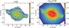 |
Fig. 1 Left: Log extinction at Hβ, c, to NGC 7009 based on the 120 s Hβ and Paschen P9–P12 images and the 10 s Hα flux image, with all images corrected for the contamination by He II and convolved with Gaussians to the same FWHM for all images, that of the Hβ image with FWHM 0.56′′. Right: Log10 Hβ surface brightness image of NGC 7009 based on the 120 s MUSE cube. |
The MUSE datasets were reduced with the instrument pipeline version 1.0 (Weilbacher et al. 2014) using the delivered calibration frames (bias, flat field, arc lamp exposures) and the pipeline astrometric, atmospheric extinction and flux calibration files. A single combined cube for each exposure level was produced, taking care to align the spatial pointing for all the data sets (using the prominent central star of NGC 7009). The standard pipeline sampling of 0.2′′ and 1.25 Å was employed for the combined cubes. As measured from the central star, the FWHM of the final cubes did not exceed 0.60′′ even at the shortest wavelength measured (a synthesized band free of strong emission lines centred on 4900 Å).
Emission line maps were produced by automatically fitting Gaussians to the prominent emission lines of H, He, N, O, S and Cl using a custom code which fits the continuum, excluding the emission lines, by a cubic spline. Maps of the flux of the various emission lines were formed. The statistical errors produced by the MUSE pipeline were propagated to the fitted line fluxes and corresponding flux error maps were also produced.
3. Derivation of extinction map
The classical method to measure the extinction to a planetary nebula is from the observed ratios of the H Balmer lines, given that the relative strengths of these lines vary weakly with temperature. Using the tabulating code of Storey & Hummer (1995), the Case B Hα/Hβ ratio varies by about 10% over the temperature range 5000 to 20 000 K and changes by 2% over the density range 100−106 cm-3. Previous measurements of the electron temperature Te in NGC 7009, such as from the [O III] 5007/4363 Å ratio, indicate values close to 10 000 K (e.g., Aller & Epps 1975; Aller & Czyzak 1977; Czyzak & Aller 1979; Barker 1983; Hyung & Aller 1995a,b; Rubin et al. 2002; Gonçalves et al. 2003; Sabbadin et al. 2004; Phillips et al. 2010; Fang & Liu 2011) with little variation. Rubin et al. (2002) determined a mean temperature averaged over the inner and outer shells and ansae of 9912 K and a fractional mean square Te variation of ≲0.01. Phillips et al. (2010) mapped the electron density from the [S II]6716/6731 Å ratio and the mean is about 4000 cm-3 in the inner and outer shells, in agreement with determinations from other Ne sensitive line ratios for small aperture/slit spectra (e.g., Fang & Liu 2011).
A first extinction map was produced from the 10 s Hα and 120 s Hβ maps. The ratio of the 10 s and 120 s Hβ flux images showed absolute agreement at the 1% level so these can be considered interchangeable, but the longer exposure image was preferred for its higher signal-to-noise. The 60 s and 120 s Hα images are both saturated in many spaxels – the line peak is saturated (top hat profile) and Gaussian fits are a poor representation of the true flux. Constant values of 104 K and 4000 cm-3 were assumed to form a map of the extinction, c, using the Galactic law (Seaton 1979; Howarth 1983) with R = 3.1. The logarithmic extinction at Hβ is related to reddening EB−V by c = 1.45 EB−V and to AV by c = 0.47 AV for this reddening law (see Howarth 1983), so the term “extinction” is used synonymously.
The level of structure in the extinction map (see Fig. 1, which is derived from the more careful analysis of the H line ratios described in Sects. 3.1−3.4) is surprising, given the low value of c towards this nebula and the indications of relatively quiescent middle-aged closed shells, apart from the more obvious structures such as the caps and the ansae. There is a general level of concordance between the dust morphology and the emission line/kinematic sub-structures of the nebula: the central flat plateau to the inner shell, two regions of higher extinction to the minor axis inner shell caps, the surrounding lower extinction outer shell and several features corresponding to the anse and minor axis polar knots. The increased extinction at the position of the central star might not be real but related to the uncertainty of correcting the H emission line fluxes for underlying stellar absorption. The extinction feature at the position of the inner shell-outer shell boundary appears as a “wave”, consisting of an inner crest and an outer trough. The extinction map of Tsamis et al. (2008) showed a hint of a decrease in c over the edge of the inner shell (their Fig. 9), but, since this occurred close to the boundary of the IFU area, its reality could not be confirmed. Examination of the HST WFPC2 F487N (Hβ) and F656N (Hα) images of NGC 7009, taken in Programme 8114, also shows evidence for the wave feature at the edge of the inner shell from the simple ratio of the images; a feature not remarked on by Rubin et al. (2002).
Given that this is the first high fidelity map of a PNe taken with MUSE, and the ratios of lines at different wavelengths might be expected to reveal artefacts due to instrumental effects or data reduction steps, doubts were naturally raised that the features in the extinction might be not be real. It is clear from Fig. 1 that some imprint of the image slicer remains in this map as seen from the perpendicular striping oriented along the axis of the slicer resulting from combination of the two views oriented 90° apart. This effect could have been mitigated by combining one or more cubes with other rotation angles, and clearly several more exposures at intermediate rotation angles would have been beneficial. However, the principal features in the extinction map are not correlated with the slicer pattern.
In order to confirm the reality of the features in this map, first instrumental, then physical causes were sought to explain these structures. If these explanations can be countered then the reality of the features in the extinction map cannot be rejected at this stage. In the following sections, first instrumental then astrophysical explanations for the apparent structures in the map are tested.
3.1. Geometrical distortion with wavelength
Since the MUSE instrument has some refractive optics (a filter and derotator in the fore-optics and the spectrograph camera for each integral field unit), there may be geometrical distortion with wavelength which is not corrected to the level of precision necessary to register the H emission line images for careful study of the spatial dependence of the extinction. Two faint stars at opposite corners of the MUSE field of view were measurable and, along with the central star, could be used to check for any uncorrected distortion. One of the faint offset stars was, however, too faint at the bluest wavelengths (~4900 Å) to measure reliably. Between Hβ and Hα no distortion could be detected, but over the range Hβ to Paschen 9 (P9: 9229 Å) a distortion of about 0.6 pixels was measured from corner-to-corner of the field. Thus there is a maximum distortion of about 0.2 pixels at the position of the wave/trough with respect to the central star between P9 and Hβ. However, the extinction features appear similar from both Hα/Hβ and Paschen/Hβ ratio maps, arguing for a small differential distortion with wavelength. By shifting the images, a distortion of ≳0.2 spaxels at the inner rim was found to enhance or weaken the wave/trough feature. Given the size scale of the major extinction features (≳1′′), it can be concluded that the residual distortion of MUSE with wavelength, over the field of NGC 7009, is not critical for this study.
3.2. Saturation/detector non-linearity
The e2v Deep Depletion CCD’s of the MUSE detectors have a tabulated saturation of 65 000e−. While the Hβ line is not saturated in any of the exposures, the Hα line is saturated in the 60 s and 120 s exposures as evident by the presence of zeros in the peak of the line in the spectra of the brightest spaxels, which occur inside the main shell. The transition inner-outer shell, where the prominent extinction feature is evident, occurs at lower Hα surface brightness than towards the centre of the inner shell and so is not clearly affected by saturation. However, non-linearity may be occurring in this vicinity to affect the Hα line peak, perhaps causing an effect on the measured extinction. The Hα surface brightness changes by about a factor two across the inner-outer shell and any non-linearity in the brighter inner shell emission would depress the Hα line count causing lower extinction to be recorded, whilst Fig. 1 shows that c is elevated just inside the shell, and lower outside where the Hα flux is lower. It appears fairly convincing that the wave-trough behaviour of the extinction across the rim of the inner shell is not due to detector saturation/non-linearity and the observation of the same pattern to the extinction measured from weaker H lines (see below) confirms this conclusion.
3.3. Wavelength dependent seeing mismatch
The atmospheric seeing varies with wavelength, approximately as λ− 1/5 (Fried 1966) and the effect on measured image quality was seen by the smaller FWHM of star images at redder wavelengths compared to 4900 Å in the MUSE cubes. Given that the wave feature of the extinction maps occurs where the surface brightness decreases by a factor ~2 over a distance of a few spaxels (<0.5′′), then the effect of the different image FWHM between the wavelengths of the H Balmer lines would modulate the ratio image which forms the basis of the extinction determination. For example for a step function across the shell, the ratio map Hα/Hβ would be expected to show a trough, since the image FWHM at Hα is lower than at Hβ. On the 10 s MUSE cube the measured FWHM of the central star varies from 0.53 to 0.50′′ between Hβ and Hα. In order to determine if this effect could be responsible for the observed wave-trough appearance across the inner shell, the Hα image was convolved with a Gaussian to the same measured FWHM as the Hβ image and the extinction map redetermined. The strength of the trough is slightly decreased, by <0.02 in c, and the wave increased by a lesser amount, but the features remain. A repeat of this test but with the 120 s Hβ map showed a similar result.
Having rejected instrumental or seeing effects as causing the pattern in extinction, astrophysical effects are now examined.
3.4. Balmer v. Paschen line ratios
The He II Pickering series 6g-4f 6560.10 Å line is within 2.7 Å of the Hα line and at the resolution of the MUSE spectra, and given the very large flux ratio (~100), will be included in the flux of the fitted Hα line. Thus the Hα flux needs to be corrected for the contamination of the He II line (~1% of the Hα surface brightness in the bright He II core of the nebula). The He II Pickering 7g-4f 5411.52 Å line was measured in all the cubes and from the Case B ratio 6560.1/5411.5 Å ratio, the 6560.1 Å observed line flux was computed using Storey & Hummer (1995) and a reddening map. The observed value of the He II 6560.10 Å line of 0.0338 × F(Hβ) tabulated by Fang & Liu (2011) appears to be too large (the theoretical ratio 6560.1/5411.5 Å is 1.75 at 104 K whilst Fang & Liu 2011 have a dereddened ratio of 2.92). Similarly the Pickering He II 8g-4f 4859.32 Å line is blended with Hβ at the MUSE resolution, so its contamination of the measured Hβ flux should also be corrected (similarly ~1% of Hβ in the core). The theoretical ratio of 4859.3 Å to 5411.5 Å was again used.
Applying both these corrections to the Hα and Hβ flux maps, the derived extinction map was re-computed. The He II line is indeed only strong inside the inner rim and is very weakly present outside the rim, so the effect of the correction to Hα and Hβ fluxes for He II is insignificant where the strongest features of the extinction are present. Inside the inner rim, where the He II is brightest, the effect on the extinction map is small, c< 0.01.
The Paschen lines higher than P9 (9229.0 Å) are also available for extinction determination. These lines also have the advantage that the contaminating He II lines (from n = 6) are weak, <0.002× 4f-3d 4685.68 Å line (or <0.02 × He II 7g-4f 5411.52 Å line) but still a fraction ~0.02 of the nearby H I line. The Paschen lines were thus also corrected for the contamination by the nearby He II n = 6 line. The logarithmic extinction correction at Hβ can then be determined from Hβ, Hα, and as many lines as desired above P9. It was decided not to use Paschen lines above P12 (8750 Å) as they become faint (<1% of flux of Hβ), more crowded and lose the wavelength leverage relative to Hβ.
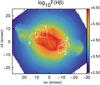 |
Fig. 2 Log10F(Hβ) image of NGC 7009 from the 120 s cube with the positions indicated for the four extraction regions across the bright rim (see Fig. 3). |
3.5. Temperature and/or density structures
The ratios of the H Balmer lines and the Paschen to Balmer lines are dependent on both Te and Ne, so the extinction map from the Balmer and Paschen lines should use both the Te and Ne maps to determine the intrinsic H line ratios. The Te map was determined from the [S III]9069/6312 Å ratio map and the Ne map from the [Cl III]5518/5538 Å ratio (to be presented in Paper II). Since the line ratios are affected by the reddening, they require to be reddening corrected before Te or Ne are determined. Initially a constant extinction value of c = 0.15 was employed, Te and Ne calculated from the dereddened [S III] and [Cl III] ratios, respectively, and then these maps used to recalculate the intrinsic H line ratios. It was found that another iteration of this procedure (also including Te or Ne maps determined from dereddened line ratios) had no effect on the extinction values exceeding the errors. Fig. 1 shows the resulting c map based on the 120 s Hβ and Paschen P9–P12 images and the 10 s Hα flux image, corrected to the same FWHM for all images, as described in Sect. 3.2, and contamination by He II as described in Sect. 3.3. The map displays mean c from the observed to theoretical H line ratios (Hα/Hβ, P9/Hβ, P10/Hβ, P11/Hβ and P12/Hβ) weighted by the inverse square of the errors determined from the observed line ratios.
An obvious cause of the wave over the inner rim could be temperature and/or density changes. The Te map from [S III]9069/6312 Å shows evidence for a mild temperature profile across the rim, with Te elevated by ~200 K over the c trough and slightly depressed in the c wave (see for example the 1D profile in Fig. 4). The [S III] emission line images used to determine Te were reddening corrected by the extinction map, but if an extinction map with a constant value is used to deredden the [S III] lines, the Te profile is more enhanced (~300 K in the c trough).
3.6. Investigation of c across the inner shell
In order to display the behaviour of c and related quantities, a number of sections across the inner rim were assembled as representative of the feature. Profiles along the cube α, δ pixel grid were constructed in four regions at the north and south edges of the inner shell and the SW and NE extremities of the shell major axis; Fig. 2 shows the four regions on the log Hβ image. Without resampling, the individual pixel profiles were assembled into an image aligning them along the rim. Figure 3 shows the resulting image for the extinction. Collapsing this image, or part of it, perpendicular to the rim, enables a detailed consideration of the overall behaviour of this feature.
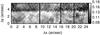 |
Fig. 3 Images of log extinction at Hβ, c, over four cross section regions of the inner shell. See Fig. 2 for the positions of the four sections. Sections 1−4 are displayed left-right, with a one pixel gap between each section. The direction towards the central star is downwards. |
The average behaviour of the extinction, c, across the rim in the direction perpendicular to the rim, with offset increasing with distance from the central area of the nebula, is shown in Fig. 4. On this plot the mean value of c across the four regions is shown (bold line) together with the profile for the region to the NE which displays the trough in extinction most strongly (dashed line). Similarly, profiles of Ne and Te are shown for the same regions. The left plot shows the Ne profile as formed from the mean Ne derived from the [S II]6716/6731 Å and [Cl III]5518/5538 Å ratios (to be presented in Paper II). The profiles of c in Fig. 4 are formed from the mean across the regions shown in Fig. 2, similarly for Ne and Te (i.e., surface averaged profiles are displayed).
To determine if changes in Te, or Ne, across the rim could be responsible for the behaviour of the extinction, an impulse profile, centred on the minimum of the trough, was synthesised to simulate rapidly varying Te, or Ne. Considering Te, a positive excursion of temperature by about 6000 K was applied: recomputing the H line theoretical strengths could then remove most of the trough, as shown in Fig. 4, right hand plot. No clear evidence for such large changes in Te have been seen in previous observations (e.g., Rubin et al. 2002; Tsamis et al. 2008), nor in the MUSE [S III] Te map (to be presented in Paper II).
A similar approach with an impulse for Ne produced only a marginal difference in the extinction profile (slightly deeper c drop at 4′′ offset for density 106 cm-3 at the peak), since the Balmer and Balmer-to-Paschen line ratios vary only slightly with densities over the range 1 cm-3 to 1 × 106 cm-3.
4. Discussion
4.1. Interstellar reddening
Given that the interstellar extinction in the direction towards NGC 7009 (l,b 37.̊8, −34.̊6) tabulated by Schlafly & Finkbeiner (2011) is greater than the low extinction values mapped, then NGC 7009 must lie at an intermediate distance along the extinction column derived by Schlegel et al. (1998) from the 100 μm emission maps. The low values of extinction, over the well-measured region of bright emission, range upwards from c = 0.04 with typical errors of 0.01. Over a larger area including the ansae and faint regions on the minor axis, the fraction of spaxels with non-zero extinction rapidly increases above c = 0.04 (some spaxels with lower extinction values occur, but can include this value within errors). Thus a likely value of extinction between the observer and the nebula is 0.04, and subtraction of this value from the measured extinction to NGC 7009 results in a map of the intrinsic extinction in the intra-nebular and circum-nebular volume.
This estimate of the line-of-sight ISM extinction to NGC 7009 can be compared to the three dimensional maps of dust extinction in the Milky Way from Pan-STARRS 1 and 2MASS photometry by Green et al. (2015). For a c = 0.04 (EB−V 0.028 mag) ISM contribution, the resulting distance to the nebula is only 270 pc. However, the error range of EB−Vv. distance modulus in the direction to NGC 7009 encompasses 0 and >1000 pc, thus not incompatible with the estimated distance of 1400 pc (Sabbadin et al. 2004), in good agreement with the value of 1450 pc deduced by Frew (2008).
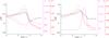 |
Fig. 4 Collapsed cross sections for the four rim regions displayed in Fig. 2 (a total extent of 25′′), showing the variation of extinction, c, Te (K) and Ne (cm-3) with relative offset across the rim (solid lines). The dashed lines refer to the mean values across the rim region 1, to the NE. Left: cross sections for Ne from the mean value determined from the [S II]6716/6731 Å and [Cl III]5518/5538 Å ratios and Te from the [S III]9069/6312 Å ratio and theoretical Balmer and Paschen line ratios computed for these values. Right: instead of measured Te, an impulse function (Gaussian with FWHM 0.9′′) is used with the observed Ne to compute c from the H line ratios. The size of the temperature excursion (6000 K) was chosen to remove the trough in the extinction. |
4.2. Dust-to-gas ratio
With the map of the intrinsic extinction of the nebula (from Fig. 1), and given the distribution of the nebular line-of-sight column of H, NH, the dust-to-gas ratio (D/G) can be determined. There are two methods to determine the line of sight H column: from the measured Ne and an estimate of the line of sight depth of the nebula; or from the emission of H which provides  along the line of sight. The former method involves a guess on the line of sight emitting depth of the nebula together with a correction for the number of electrons per H atom. The latter method does not require an assumption of line-of-sight depth since the integral of the H column density is determined from the surface brightness in an H line and the line emissivity; the depth variation of electron density is not known, so the assumption of a constant value along the line of sight is adopted. The former method requires the distance for the estimate of the line of sight column, and so the latter method, not requiring this assumption, is preferred.
From the Hβ flux map, with the [Cl III]5518/5538 Å electron density and the electron temperature from [S III]9069/6312 Å to calculate the Hβ emissivity (Storey & Hummer 1995), NH + was computed. Then ratioing this with the extinction map, after subtracting the interstellar value, results in a map of AV/NH. The presence of only weak lines of neutral species, such as [O I], which will be presented in Paper II, confirm the small contribution of neutral H to the total H budget, so that NH + = NH can be assumed. For convenience the AV/NH map was expressed as a fraction of the Milky Way ISM value of 5.07 × 10⁻²² mag cm-2, from the mean NH/EB−V value quoted by Gudennavar et al. (2012; adopting R = 3.1 since NH/EB−V is quoted) and the resulting map is shown in Fig. 5. Over the inner shell, the mean value is about 0.9, but rises in the outer shell and the streams to values around 5 (as in this region the surface brightness in H lines is lower, the extinction slightly depressed relative to the inner shell and the density about a factor 2 lower). The AV/NH profiles across the rim sections are plotted in Fig. 6 similarly to Fig. 4, including also the profiles of c and Ne.
The D/G map (Fig. 5) can be compared with the map produced from NH using the line-of-sight depth and Ne. A line-of-sight depth of 20′′ was used (based on an prolate nebula form, cf., Steffen et al. 2009, and see Sect. 4.4) and a ratio Ne/NH of 1.14 (based on the chemical abundances listed by Sabbadin et al. 2004). The pattern of AV/NH is similar (not shown), in particular the rising value in the outer regions. The absolute values are smaller by a factor ~2, suggesting a filling factor value of around 50% between the H density and the matter density based on Ne, or a distance of 750 pc for an assumed filling factor of 1.0.
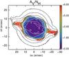 |
Fig. 5 The dust-to-gas ratio map of NGC 7009 as expressed by the ratio AV/NH in terms of the MW ISM value of Gudennavar et al. (2012). The contours correspond to the log10F(Hβ) image of NGC 7009 from the 120 s cube, shown in Fig. 1. |
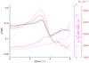 |
Fig. 6 Collapsed mean cross sections for the four rim regions displayed in Fig. 2, showing the variation of extinction, c, AV/NH and Ne (cm-3) with relative offset across the rim (solid lines), and for rim region 1 (dashed lines); cf., Fig. 4. The dust-to-gas ratio AV/NH is expressed as a fraction of the ISM value of 5.07 × 10⁻²² mag cm-2 from Gudennavar et al. (2012). |
The integrated AV/NH for NGC 7009 with respect to the interstellar value can be computed in several ways depending on how the surface weighting is performed. Weighting the AV/NH map by the observed Hβ flux map, results in an integrated AV/NH value of 0.87; if weighted by  , the value is 0.99; alternatively weighting by
  gives a value of 1.38; and finally weighting by the electron density map (mean of Ne from [S II] and [Cl III] ratios) gives an integrated AV/NH value of 2.21. Weighting by electron density is the least comparable to the ISM value determined from studies of the extinction and neutral gas column to nearby stars; the value integrated by the PN is the most comparable, but for unresolved PNe, the weighting will, by default, be by Hβ flux.
The integrated AV/NH value can be compared with the ionized gas-to-dust mass ratio derived from the spectral energy distribution fit, including the millimetre and sub-millimetre measurements from Planck, of 235 (Planck Collaboration VI 2015), although with an uncertainty of ±50%. The line-of-sight dust extinction is calculated assuming that the dust absorbs and scatters the emission from the gas. With the assumption that the dust is uniformly mixed with the ionized gas in proportion to the density, then the measured line-of sight dust extinction is about a factor two less than the total amount of dust available for extinction (i.e., if all the dust was present in the foreground), depending on the variation of emission (∝density2) with radius. Correcting for the mass fraction of metals (35%, from Sabbadin et al. 2004) and assuming astronomical silicate grains (Draine 1985), an estimate of the mass of the dust responsible for the extinction can be made from Cext calculated from Mie theory and the mass density (ρSil = 3.2 g cm-3; Draine & Lee 1984).
Assuming an MRN (Mathis et al. 1977) spherical grain size distribution for silicate (size distribution ∝ a-3.5 and amin 0.005 μm, amax 0.25 μm), the mass of obscuring dust is only responsible for about 85% of the dust mass from thermal emission. If the lower bound on the grain radius is increased from the standard MRN silicate value, to 0.007 μm, then the masses of obscuring and emitting dust can be made equal. The upper bound for the 50% error on the Planck Collaboration VI (2015) gas-to-dust mass ratio is compatible with the AV/NH value for the standard MRN silicate ISM size distribution. A greater mass in thermal dust, from cooler or warmer dust components than measured from the SED fits, would increase the mismatch with the extinction dust mass, requiring the presence of larger grains.
It is noteworthy that both (i) the integrated AV/NH (based on weighting and corrected for the effects of extinction measurement from gas mixed with dust using the model presented in Sect. 4.4) of 2.2 relative to the ISM value and (ii) the integrated gas-to-dust mass ratio of 235 from (Planck Collaboration VI 2015), are similar to the ISM values (256 for the latter using the determination by Draine 2011 and He/H = 0.1). The conclusion is that NGC 7009 is marginally a net dust producer. Since the AV/NH measurements only pertain to the dust in proximity to the ionized gas, such a conclusion would be modified by the presence of a more extended dust (and gas) component which is the remnant of the long-term mass loss on the AGB before the PN phase. NGC 7009 does not, however, have an enhanced C/O ratio, and its O/H value is slightly below solar, so its heavy element fraction is probably similar to that of the ISM out of which its progenitor star formed. The fraction of its heavy elements that form dust during the AGB phase is thus likely to be similar to the original ISM fraction, since the CNO cycle only recycles elements already present in the progenitor star.
However, PNe which have C/O > 1, as well as Type I PNe whose CNO/H ratio significantly exceeds that of the ISM, have undergone the triple-alpha process, producing primary carbon (some of which may later have been converted to N by hot bottom burning). Such PNe may have AV/NH ratios that considerably exceed the ISM value and similar MUSE observations to those on NGC 7009 could be indicative.
4.3. Effect of Te variation
If the ionic temperature is much higher across the inner shell boundary (explored by applying a Te impulse across the extinction trough), whilst showing only small evidence of raised temperature in the [S III] Te (see Fig. 4), then it is suggested that the lower c domain outside the bright rim might also be attributable to higher H temperatures. This would, however, imply lack of equipartition between electrons and H+. Interestingly the PN hydrodynamic model A4 of Perinotto et al. (1998) does show an ~5000 K temperature rise at the outer rim for an optically thin nebula, corresponding to the position of the isothermal shock.
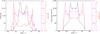 |
Fig. 7 Left: the observed profiles of the Hβ flux (relative units, in black), extinction c (magenta) and dust-to-gas ratio (AV/NH, in red) along a strip 2′′ wide along the minor axis of NGC 7009. The extinction refers to the nebular component and an assumed interstellar component (of c = 0.04) has been subtracted. Right: plausible model profiles of emission (assumed Hβ), extinction c and dust-to-gas ratio (from sums of model gas and dust columns) plotted with scaling and plot symbols similar to the observed profiles. The model consists of two prolate ellipsoidal dust shells; see text for details. |
From studies of the H temperature from the Balmer (and Paschen) jump in PNe (Zhang et al. 2004; Liu & Danziger 1993), it was found that Te(Bal) is generally systematically lower than Te determined from [O III] 5007/4363 Å. In the case of NGC 7009, the Balmer and Paschen jump temperatures were determined as 7200 K and 5800 K, respectively (Zhang et al. 2004); thus 3000−4000 K lower than from the forbidden line temperatures ([O III] and [S III]). The region sampled by the spectra used to fit the Balmer and Paschen jumps is not explicitly specified, but appears to correspond to the bright main shell. Although it cannot be stated with certainty that there is no temperature impulse at the main shell rim applicable to H and coincident with the extinction trough, this appears unlikely given that the majority of PNe (cf., Zhang et al. 2004) show Te(Bal) <Te[O III].
4.4. Possible model
In order to better understand the morphology of the extinction and AV/NH, a very simple 3D geometrical model of the emission and dust was constructed. Two co-centred ellipsoidal forms for the gas emission and dust density were chosen as the minimum required to model the gross features; based on the Shape model of Steffen et al. (2009), prolate ellipsoids were used. The projected emission model was guided by the Hβ image (Fig. 1) and the two ellipsoids, or ellipsoidal shells, had differing radial emission dependence or shell thickness, with sizes approximately scaled to the relative dimensions of NGC 7009. Ellipsoidal shells were used for the dust number density but with differing radial dependence. The 3D models were projected along the line of sight, without considering any body tilt of the ellipsoids. Assuming an extinction coefficient appropriate for small silicate grains, the model emission is extinction corrected depending on the length of the line-of-sight dust column between the emitting point and the observer. Projected maps of the emission, with and without internal extinction, are output and the c map is calculated from their ratio by analogy to the observed map (Fig. 1), which used the observed images of several H lines to determine c.
Various radial dependencies for emission and dust in the two ellipsoids representing the inner and outer shells were tried. Figure 7 (left) shows a slice along the minor axis of the nebula taken 3.5′′ east of the central star for the Hβ flux, extinction c and AV/NH. The minor axis was selected since the ansae and FLIERS occur on the major axis. These profiles were qualitatively compared to the model profiles at the equivalent position (not a fit), with model D/G taken as the ratio of dust density to model density ( ). A fair match was found with a constant density inner emission ellipsoidal shell, and a filled volume with r-0.5 for the outer region; for the inner dust ellipsoid, dust density ∝ r-0.3 was adopted and r-2.5 for the outer dust shell. Figure 7 (right) shows the model profiles, with the emission and D/G arbitrarily scaled to the same range as the observations. The normalization for the extinction is provided by the dust density in the model. While physical parameters cannot be directly determined from these models, which are by no means unique, a few features are obvious: a prolate nebula does not conflict with the gas and dust imaging; the radial dependence of the emission differs in the inner and outer shells; the dust and emission (gas) radial dependencies differ (in order to give D/G increasing with distance from the nebular centre); at least two dust shells are necessary to explain the extinction structure; the outer volume is more filled by dust (shell thick) to provide the extinction in front of the inner shell.
The main aim of these simple models was to explore if a combination of different emission and dust shells could give rise to the trough in the extinction at the outer edge of the inner shell. The combination of extinction falling abruptly at the edge of the inner shell, superposed on the gently rising extinction profile of the outer shell, does mimic the effect of the trough, so it is feasible that this is one possible explanation. The other explanation is that dust is genuinely destroyed in a narrow annulus around the inner shell. Other more exotic causes not involving dust destruction could also be considered, such as magneto-hydrodynamic interactions between the wind and large-scale magnetic fields, as explored by van Marle et al. (2014) and Albertazzi et al. (2014).
4.5. Origin of the dust wave feature
The trough in extinction appears to separate the two plateaux of dust extinction which correspond to the inner and outer shells. However, the extinction trough is not obvious in the electron density profile (Fig. 4) as this is steeply declining in this region; nor is the trough apparent in the dust-to-gas map (Fig. 5) or the 1D profile (Fig. 6). Thus one interpretation of this feature is that it corresponds to a short decrease in the mass loss rate (both dust and gas) during the AGB phase. For a typical AGB expansion velocity of ~10 km s-1, this variation in mass loss would have occurred around 3500 yr ago (assumed distance 1400 pc), for a period of a few hundred years, which seems recent relative to the assumed age of the PN outer shell of ~2000 yr (Sabbadin et al. 2004), and older for the halo. Conversely the elevated extinction just inside the rim of the inner shell (He II ionization front) could indicate an earlier increase in the dust mass loss and is also associated with an increase in the gas density (Fig. 6). The models of colliding winds of PNe show that the shock propagating into the slow AGB wind tends to dilute any strong density contrasts (cf., Steffen et al. 2008) so these features may have been much stronger and narrower before the PN phase.
The presence of two plateaux of dust extinction – inner shell and outer shell – separated by a trough is suggestive of a dust destruction mechanism across the inner-outer shell boundary. The classical mechanism to destroy dust is sputtering by energetic particles (Barlow 1978a), such as in shocks as considered in detail for supernovae by Bocchio et al. (2014), or by grain-grain collisions (Barlow 1978b). However, there is no observational evidence for a shock in this region – as for example from broadening or wings to line profiles or kinematic discontinuity (Tsamis et al. 2008; Sabbadin et al. 2004; Hyung et al. 2014) nor any indication of an increase in ionization through extra heating (e.g., enhanced He II emission or other high ionization lines). Velocities in excess of 50 km s-1 are typically required to sputter dust, especially since NGC 7009 shows evidence for silicate dust which requires higher velocities for sputtering than carbonaceous dust (Bocchio et al. 2014). Based on Fig. 5 of Sabbadin et al. (2004), the expansion velocity in the vicinity of the trough is only ~20 km s-1 making significant thermal sputtering by protons and heavier atoms unlikely.
The ionization conditions change at the inner/outer shell boundary, in particular the He II emission prominent within the main shell is not present outside implying a confinement of the highest ionization gas (hν> 54 eV) within the main shell. The X-ray maps of NGC 7009, Guerrero et al. (2002) from XMM-Newton and, in particular, from Kastner et al. (2012) for Chandra, show diffuse million degree gas confined within the main shell. The spatial resolution of the Chandra maps is ~0.5′′ and the Chandra ACIS soft-band image in Kastner et al. (2012) does not show the 10% contour beyond the main shell. The X-ray photons could be responsible for some dust processing, but grain heating is the major effect of an X-ray flux (Weingartner et al. 2006). The hot, X-ray emitting diffuse gas could be responsible for some dust destruction through thermal sputtering (Draine & Salpeter 1979; and Barlow 1978a). However, the crest of higher extinction inside the ionization front would be expected to be subject to stronger interaction with hot gas, yet remains as a significant peak in extinction suggesting that the X-ray emitting gas cannot account for the presence of the trough feature.
If some dust destruction is associated with the trough feature, an estimate of the fraction of dust destroyed can be derived by subtracting a smoothed version of the extinction map from the map (Fig. 1). The extinction trough corresponds to a drop of c of ~0.03. Depending on the smoothing kernel applied (Gaussians with FWHM in the range 1.4 to 3.3′′ were tried), a range of 3−5% reduction in the total extinction over the whole nebula is indicated for this feature. This is very low level and tends to indicate that any destruction of dust from the previous AGB phase by the PN phase, which is attributable to the presence of the trough feature, is minimal.
4.6. Reflection nebula origin of the extinction trough?
If the elevated extinction observed over the central zone of NGC 7009 is caused by a shell of dust at the rim of the volume, as suggested by the geometrical gas and dust model in Sect. 4.4, then the lines of sight at the projected edge of the inner shell would be expected to show higher extinction as a longer dust column is probed. However, the opposite is the case and the extinction is lower (Figs. 3 and 4). Assuming that the extinction increase measured inside the inner shell relative to the outer shell (c ~ 0.024, EB−V 0.016 mag.) represents the extinction derived from an annular dust shell around the the inner shell, the expected tangential increase in line of sight extinction at its edge can be estimated. For a simple geometrical annulus of width 0.5′′ around the inner shell, the tangent through the prolate shell has an extinction increased by up to 9× (13× for a oblate form); these figures are corroborated by test vectors placed at various positions around the inner shell across the trough in the extinction image (Fig. 1).
The suggestion then arises if the trough in the c map could arise from scattering of radiation from the bright inner nebula by a dust shell causing “blueing” of the spectra and hence lower measured extinction. The reduction in extinction from the hypothesized dust shell to the measured value in the trough suggests a range of EB−V of 0.3−0.4 mag. Such values are not untypical of the “blueing” of reflection nebulae, e.g., EB−V change ≲0.5 mag. for the reflection nebula NGC 1435, Merope (Hanner 1971). The geometrical situation of scattering of radiation from an extended central source in NGC 7009 is, however, very distinct from the scattering of radiation from a single star in NGC 1435 and the masses of gas and dust in a PN are much lower than in typical reflection nebulae around young stars. A measurement of the linear polarization across the trough could confirm the role of dust scattering in this region; so far only aperture polarimetry over the outer halo has been performed in NGC 7009 (Leroy et al. 1986), with measured values of ~0.5−1%. Also mapping of the thermal dust emission could determine the presence of a thick dust shell in this vicinity.
5. Conclusions
Moderately extended planetary nebulae are well suited to integral field spectroscopy with an IFU as large as MUSE in its wide field mode, which is capable of covering most of the bright emission in a single exposure. The MUSE spaxel scale allied with good seeing observations can reveal a wealth of structures in a range of emission lines useful for diagnostics of extinction, electron temperature and density, ionization stratification and chemical abundances over the whole nebula surface. Such data are ideally suited to detailed comparison with images and spectra at other wavelengths, such as in the infrared, mm/sub-mm and radio.
Analysis of the Balmer (Hβ and Hα) and brighter Paschen series (P9–P12) lines have been described based on MUSE science verification observations of the well studied PN NGC 7009. The extinction map reveals a wealth of structures from large scale shells to individual morphological features. Internal dust extinctions in typical PNe have never been mapped before, except for the extreme cases of NGC 7027 (Walton et al. 1988) and NGC 6302 (Matsuura et al. 2005), due to the gas and dust column densities being more than an order magnitude smaller than those in typical HII regions. This result for NGC 7009 was unexpected and attests to the sensitivity of 2D mapping of extinction with MUSE.
A map of AV/NH has been derived from comparison of the extinction map with the H line emission for the first time in a PN. An unusual feature in the extinction map, of a crest and trough at the outer edge of the inner emission shell, was investigated to determine if it could be connected with dust reprocessing within the ionized nebula. No convincing evidence was found that it is not simply an intrinsic feature of the dust ejected in the antecedent AGB phase.
Acknowledgments
We would like to thank the MUSE science verification team for the very successful conduct of the observations and the whole MUSE team, led by Roland Bacon, for providing such a high fidelity IFU ideally matched to spectroscopy of Galactic planetary nebulae. We also thank the anonymous referee for comments and suggestions.
References
- Albertazzi, B., Ciardi, A., Nakatsutsumi, M., et al. 2014, Science, 346, 325 [NASA ADS] [CrossRef] [Google Scholar]
- Aller, L. H., & Czyzak, S. J. 1977, PASP, 89, 612 [NASA ADS] [CrossRef] [Google Scholar]
- Aller, L. H., & Epps, H. W. 1975, ApJ, 197, 175 [NASA ADS] [CrossRef] [Google Scholar]
- Balick, B., Alexander, J., Hajian, A. R., et al. 1998, AJ, 116, 360 [NASA ADS] [CrossRef] [Google Scholar]
- Barker, T. 1983, ApJ, 267, 630 [NASA ADS] [CrossRef] [Google Scholar]
- Barlow, M. J. 1978a, MNRAS, 183, 367 [NASA ADS] [CrossRef] [Google Scholar]
- Barlow, M. J. 1978b, MNRAS, 183, 397 [NASA ADS] [CrossRef] [Google Scholar]
- Bocchio, M., Jones, A. P., & Slavin, J. D. 2014, A&A, 570, A32 [NASA ADS] [CrossRef] [EDP Sciences] [Google Scholar]
- Bohigas, J., Lopez, J. A., & Aguilar, L. 1994, A&A, 291, 595 [NASA ADS] [Google Scholar]
- Czyzak, S. J., & Aller, L. H. 1979, MNRAS, 188, 229 [NASA ADS] [CrossRef] [Google Scholar]
- Draine, B. T. 1985, ApJS, 57, 587 [NASA ADS] [CrossRef] [Google Scholar]
- Draine, B. T. 2011, Physics of the Interstellar and Intergalactic Medium (Princeton University Press) [Google Scholar]
- Draine, B. T., & Lee, H. M. 1984, ApJ, 285, 89 [Google Scholar]
- Draine, B. T., & Salpeter, E. E. 1979, ApJ, 231, 438 [NASA ADS] [CrossRef] [Google Scholar]
- Fang, X., & Liu, X.-W. 2011, MNRAS, 415, 181 [NASA ADS] [CrossRef] [Google Scholar]
- Fang, X., & Liu, X.-W. 2013, MNRAS, 429, 2791 [NASA ADS] [CrossRef] [Google Scholar]
- Frew, D. J. 2008, Ph.D. Thesis, Department of Physics, Macquarie University, NSW 2109, Australia [Google Scholar]
- Fried, D. L. 1966, J. Opt. Soc., 56, 1372 [NASA ADS] [CrossRef] [Google Scholar]
- Gonçalves, D. R., Corradi, R. L. M., Mampaso, A., & Perinotto, M. 2003, ApJ, 597, 975 [NASA ADS] [CrossRef] [Google Scholar]
- Green, G. M., Schlafly, E. F., Finkbeiner, D. P., et al. 2015, ApJ, 810, 25 [NASA ADS] [CrossRef] [Google Scholar]
- Gudennavar, S. B., Bubbly, S. G., Preethi, K., & Murthy, J. 2012, ApJS, 199, 8 [NASA ADS] [CrossRef] [Google Scholar]
- Guerrero, M. A., Gruendl, R. A., & Chu, Y.-H. 2002, A&A, 387, L1 [NASA ADS] [CrossRef] [EDP Sciences] [Google Scholar]
- Hanner, M. S. 1971, ApJ, 164, 425 [NASA ADS] [CrossRef] [Google Scholar]
- Howarth, I. D. 1983, MNRAS, 203, 301 [NASA ADS] [CrossRef] [Google Scholar]
- Hyung, S., & Aller, L. H. 1995a, MNRAS, 273, 973 [NASA ADS] [CrossRef] [Google Scholar]
- Hyung, S., & Aller, L. H. H. 1995b, MNRAS, 273, 958 [NASA ADS] [CrossRef] [Google Scholar]
- Hyung, S., Lee, S.-J., & Sung, E.-C. 2014, Ap&SS, 352, 71 [NASA ADS] [CrossRef] [Google Scholar]
- Kastner, J. H., Montez, Jr., R., Balick, B., et al. 2012, AJ, 144, 58 [NASA ADS] [CrossRef] [EDP Sciences] [Google Scholar]
- Leroy, J. L., Le Borgne, J. F., & Arnaud, J. 1986, A&A, 160, 171 [NASA ADS] [Google Scholar]
- Liu, X.-W., & Danziger, J. 1993, MNRAS, 263, 256 [NASA ADS] [CrossRef] [Google Scholar]
- Liu, X.-W., Storey, P. J., Barlow, M. J., & Clegg, R. E. S. 1995, MNRAS, 272, 369 [NASA ADS] [CrossRef] [Google Scholar]
- Mathis, J. S., Rumpl, W., & Nordsieck, K. H. 1977, ApJ, 217, 425 [NASA ADS] [CrossRef] [Google Scholar]
- Matsuura, M., Zijlstra, A. A., Molster, F. J., et al. 2005, MNRAS, 359, 383 [NASA ADS] [CrossRef] [Google Scholar]
- Mendez, R. H., Kudritzki, R. P., Herrero, A., Husfeld, D., & Groth, H. G. 1988, A&A, 190, 113 [NASA ADS] [Google Scholar]
- Mendez, R. H., Kudritzki, R. P., & Herrero, A. 1992, A&A, 260, 329 [NASA ADS] [Google Scholar]
- Perinotto, M., Kifonidis, K., Schoenberner, D., & Marten, H. 1998, A&A, 332, 1044 [NASA ADS] [Google Scholar]
- Phillips, J. P., Cuesta, L. C., & Ramos-Larios, G. 2010, MNRAS, 409, 881 [NASA ADS] [CrossRef] [Google Scholar]
- Planck Collaboration VI. 2015, A&A, 573, A6 [NASA ADS] [CrossRef] [EDP Sciences] [Google Scholar]
- Rodríguez, L. F., & Gómez, Y. 2007, Rev. Mex. Astron. Astrofis., 43, 173 [Google Scholar]
- Rubin, R. H., Bhatt, N. J., Dufour, R. J., et al. 2002, MNRAS, 334, 777 [NASA ADS] [CrossRef] [Google Scholar]
- Sabbadin, F., Turatto, M., Cappellaro, E., Benetti, S., & Ragazzoni, R. 2004, A&A, 416, 955 [NASA ADS] [CrossRef] [EDP Sciences] [Google Scholar]
- Schlafly, E. F., & Finkbeiner, D. P. 2011, ApJ, 737, 103 [NASA ADS] [CrossRef] [Google Scholar]
- Schlegel, D. J., Finkbeiner, D. P., & Davis, M. 1998, ApJ, 500, 525 [NASA ADS] [CrossRef] [Google Scholar]
- Seaton, M. J. 1979, MNRAS, 187, 73P [NASA ADS] [CrossRef] [Google Scholar]
- Steffen, M., Schönberner, D., & Warmuth, A. 2008, A&A, 489, 173 [NASA ADS] [CrossRef] [EDP Sciences] [Google Scholar]
- Steffen, W., Espíndola, M., Martínez, S., & Koning, N. 2009, Rev. Mex. Astron. Astrofis., 45, 143 [NASA ADS] [Google Scholar]
- Storey, P. J., & Hummer, D. G. 1995, MNRAS, 272, 41 [NASA ADS] [CrossRef] [Google Scholar]
- Tsamis, Y. G., Walsh, J. R., Péquignot, D., et al. 2008, MNRAS, 386, 22 [NASA ADS] [CrossRef] [Google Scholar]
- van Marle, A. J., Cox, N. L. J., & Decin, L. 2014, A&A, 570, A131 [NASA ADS] [CrossRef] [EDP Sciences] [Google Scholar]
- Walton, N. A., Pottasch, S. R., Reay, N. K., & Taylor, A. R. 1988, A&A, 200, L21 [NASA ADS] [Google Scholar]
- Weilbacher, P. M., Streicher, O., Urrutia, T., et al. 2014, in Astronomical Data Analysis Software and Systems XXIII, eds. N. Manset, & P. Forshay, ASP Conf. Ser., 485, 451 [Google Scholar]
- Weingartner, J. C., Draine, B. T., & Barr, D. K. 2006, ApJ, 645, 1188 [NASA ADS] [CrossRef] [Google Scholar]
- Zhang, Y., Liu, X.-W., Wesson, R., et al. 2004, MNRAS, 351, 935 [NASA ADS] [CrossRef] [Google Scholar]
All Figures
|
Fig. 1 Left: Log extinction at Hβ, c, to NGC 7009 based on the 120 s Hβ and Paschen P9–P12 images and the 10 s Hα flux image, with all images corrected for the contamination by He II and convolved with Gaussians to the same FWHM for all images, that of the Hβ image with FWHM 0.56′′. Right: Log10 Hβ surface brightness image of NGC 7009 based on the 120 s MUSE cube. |
| In the text | |
|
Fig. 2 Log10F(Hβ) image of NGC 7009 from the 120 s cube with the positions indicated for the four extraction regions across the bright rim (see Fig. 3). |
| In the text | |
|
Fig. 3 Images of log extinction at Hβ, c, over four cross section regions of the inner shell. See Fig. 2 for the positions of the four sections. Sections 1−4 are displayed left-right, with a one pixel gap between each section. The direction towards the central star is downwards. |
| In the text | |
|
Fig. 4 Collapsed cross sections for the four rim regions displayed in Fig. 2 (a total extent of 25′′), showing the variation of extinction, c, Te (K) and Ne (cm-3) with relative offset across the rim (solid lines). The dashed lines refer to the mean values across the rim region 1, to the NE. Left: cross sections for Ne from the mean value determined from the [S II]6716/6731 Å and [Cl III]5518/5538 Å ratios and Te from the [S III]9069/6312 Å ratio and theoretical Balmer and Paschen line ratios computed for these values. Right: instead of measured Te, an impulse function (Gaussian with FWHM 0.9′′) is used with the observed Ne to compute c from the H line ratios. The size of the temperature excursion (6000 K) was chosen to remove the trough in the extinction. |
| In the text | |
|
Fig. 5 The dust-to-gas ratio map of NGC 7009 as expressed by the ratio AV/NH in terms of the MW ISM value of Gudennavar et al. (2012). The contours correspond to the log10F(Hβ) image of NGC 7009 from the 120 s cube, shown in Fig. 1. |
| In the text | |
|
Fig. 6 Collapsed mean cross sections for the four rim regions displayed in Fig. 2, showing the variation of extinction, c, AV/NH and Ne (cm-3) with relative offset across the rim (solid lines), and for rim region 1 (dashed lines); cf., Fig. 4. The dust-to-gas ratio AV/NH is expressed as a fraction of the ISM value of 5.07 × 10⁻²² mag cm-2 from Gudennavar et al. (2012). |
| In the text | |
|
Fig. 7 Left: the observed profiles of the Hβ flux (relative units, in black), extinction c (magenta) and dust-to-gas ratio (AV/NH, in red) along a strip 2′′ wide along the minor axis of NGC 7009. The extinction refers to the nebular component and an assumed interstellar component (of c = 0.04) has been subtracted. Right: plausible model profiles of emission (assumed Hβ), extinction c and dust-to-gas ratio (from sums of model gas and dust columns) plotted with scaling and plot symbols similar to the observed profiles. The model consists of two prolate ellipsoidal dust shells; see text for details. |
| In the text | |
Current usage metrics show cumulative count of Article Views (full-text article views including HTML views, PDF and ePub downloads, according to the available data) and Abstracts Views on Vision4Press platform.
Data correspond to usage on the plateform after 2015. The current usage metrics is available 48-96 hours after online publication and is updated daily on week days.
Initial download of the metrics may take a while.