| Issue |
A&A
Volume 577, May 2015
|
|
|---|---|---|
| Article Number | L2 | |
| Number of page(s) | 6 | |
| Section | Letters | |
| DOI | https://doi.org/10.1051/0004-6361/201525777 | |
| Published online | 12 May 2015 | |
Nascent bipolar outflows associated with the first hydrostatic core candidates Barnard 1b-N and 1b-S⋆,⋆⋆,⋆⋆⋆
1 LERMA, Observatoire de Paris, CNRS UMR 8112, École Normale Supérieure, PSL research university, 24 rue Lhomond, 75231 Paris Cedex 05, France
e-mail: This email address is being protected from spambots. You need JavaScript enabled to view it.
2 Sorbonne Universités, , UPMC université Paris 06, 75000 Paris, France
3 Institut de Radioastronomie Millimétrique (IRAM), 300 rue de la Piscine, 38406 Saint-Martin d’ Hères, France
4 Observatorio Astronómico Nacional (OAN, IGN), Apdo 112, 28803 Alcalá de Henares, Spain
5 Instituto de Ciencia de Materiales de Madrid (ICMM-CSIC), 28049, Cantoblanco, Madrid, Spain
6 Centre de Recherche Astronomique de Lyon (CRAL), École Normale Supérieure de Lyon, CNRS-UMR 5574, 69364 Lyon Cedex 07, France
7 INAF, Istituto di Radioastronomia, via P. Gobetti 101, 40129 Bologna, Italy
Received: 31 January 2015
Accepted: 14 April 2015
Abstract
In the theory of star formation, the first hydrostatic core (FHSC) phase is a critical step in which a condensed object emerges from a prestellar core. This step lasts about one thousand years, a very short time compared with the lifetime of prestellar cores, and therefore is hard to detect unambiguously. We present IRAM Plateau de Bure observations of the Barnard 1b dense molecular core, combining detections of H2CO and CH3OH spectral lines and dust continuum at 2.3′′ resolution (~500 AU). The two compact cores B1b-N and B1b-S are detected in the dust continuum at 2 mm, with fluxes that agree with their spectral energy distribution. Molecular outflows associated with both cores are detected. They are inclined relative to the direction of the magnetic field, in agreement with predictions of collapse in turbulent and magnetized gas with a ratio of mass to magnetic flux somewhat higher than the critical value, μ ~ 2−7. The outflow associated with B1b-S presents sharp spatial structures, with ejection velocities of up to ~7 km s-1 from the mean velocity. Its dynamical age is estimated to be ~2000 yr. The B1b-N outflow is smaller and slower, with a short dynamical age of ~1000 yr. The B1b-N outflow mass, mass-loss rate, and mechanical luminosity agree well with theoretical predictions of FHSC. These observations confirm the early evolutionary stage of B1b-N and the slightly more evolved stage of B1b-S.
Key words: ISM: clouds / ISM: jets and outflows / ISM: individual objects: Barnard 1b / stars: formation
Based on observations carried out with the IRAM Plateau de Bure Interferometer. IRAM is supported by INSU/CNRS (France), MPG (Germany) and IGN (Spain).
Appendices are available in electronic form at http://www.aanda.org
FITS files for the H2CO and CH3OH mosaics are only available at the CDS via anonymous ftp to cdsarc.u-strasbg.fr (130.79.128.5) or via http://cdsarc.u-strasbg.fr/viz-bin/qcat?J/A+A/577/L2
© ESO, 2015
1. Introduction
In the current theory of low-mass star formation, the first condensed object to be formed in the collapse of the prestellar cores is the first hydrostatic core (FHSC). During this rather short-lived phase of less than about a thousand years, the collapse slows down until the core temperature rises above about 2000 K, when molecular hydrogen starts to dissociate (Larson 1969). Predictions of the spectral energy distribution (SED) of FHSCs as well as their density structure and kinematics are available thanks to magnetohydrodynamic (MHD) simulations (e.g. Commerçon et al. 2012a,b). Their observational characteristics are intermediate between those of a prestellar core and a class 0 protostar: i) a SED peaking beyond ~100 μm similar to that of a prestellar core; and ii) a compact structure of ~500 AU. These features are found in very low luminosity objects (VeLLOs), which are compact sources characterized by an internal luminosity lower than 0.1 L⊙ (di Francesco et al. 2007). They can be class 0 or class I young stellar objects (YSOs), proto-brown dwarfs, or FHSC candidates. VeLLOs exhibit contrasting outflow properties, from extended and collimated lobes down to faint, slow, and compact flows (e.g. Dunham et al. 2011). The characterization of an FHSC candidate requires studying its SED and the gas kinematics of its envelope and molecular outflow. Another important theoretical prediction of the FHSC stage is the presence of a compact, slow, and poorly collimated outflow, whose properties depend on the strength and orientation of the magnetic field relative to the rotation axis of the prestellar core (Hennebelle & Fromang 2008; Tomida et al. 2010; Ciardi & Hennebelle 2010; Machida 2014).
Observation parameters.
As of today, several FHSC candidates have been found in star-forming regions in the Perseus molecular cloud. Of these, the Barnard 1 region has attracted attention because of it has dense cores at different evolutionary stages: B1a and B1c are each hosting a class 0 YSO with developed outflows (Hatchell et al. 2007), while B1b has recently been proposed to host two FHSCs based on the SED analysis of Herschel and Spitzer data (Pezzuto et al. 2012). In detail, three remarkable sources are detected in B1b: an infrared source detected by Spitzer, with strong absorption from ices B1b-W (Jørgensen et al. 2006; Evans et al. 2009), and two compact (sub)millimeter continuum sources B1b-N and B1b-S that are the FHSC candidates. The three sources are deeply embedded in the surrounding protostellar core, which seems essentially unaffected by them, as shown by its high column density, N(H2) ~ 1023 cm-2 and low kinetic temperature, TK = 12 K (Lis et al. 2010).
Because of the nearby B1a and B1c YSOs, it has been difficult to associate molecular outflows with either B1b-N or B1b-S. Hatchell et al. (2007) found high-velocity emission close to B1b-S in their CO(3–2) survey of the region, but without a clear association with either source. Broad line profiles and line wings have also been detected in some species such as CH3OH (Öberg et al. 2010) and the excited transition NH3(3, 3) (Lis et al. 2010), without assignment to any of the B1b sources. New SMA observation of CO(2–1) at a resolution of 6.2′′ × 3.9′′ unambiguously detected molecular outflows with the B1b-S and B1b-W and possibly B1b-N (Hirano & Liu 2014).
To better understand the nature of the three objects embedded in B1b, we have obtained 2′′ resolution data with the IRAM Plateau de Bure interferometer, targeting methanol and formaldehyde lines in the 2 mm spectral window. Following Hirano & Liu (2014), we adopt a distance of 230 pc for Barnard 1, implying that 2′′ corresponds to ~500 AU. The observations are presented in Sect. 2 and are discussed in Sect. 3 with particular emphasis on the molecular outflows.
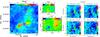 |
Fig. 1 Left: integrated intensity (from 0 to 14 km s-1) and velocity field of the H2CO(20,2−10,1) line. Purple contours show the continuum emission at 145 GHz. The plus signs indicate the positions of B1b-N and B1b-S. The star shows the position of B1b-W. The black ellipse shows the beam size. The small panels show the centroid velocity towards B1b-N (top) and B1b-S (bottom) in km s-1. Right: integrated intensity images (from 1.5 to 12.5 km s-1) of the four CH3OH lines detected towards B1b: from left to right and top to bottom: 30−20 A, 3-1 − 2-1 E, 30−20 E and 32−22 E. The intensity scale in K km s-1 is given by the color bar on the right. Contours of the 30−20 A line are superimposed in all plots, ranging from 1 to 20 K km s-1 with a step of 3 K km s-1. Offsets are given relative to the pointing center given in Table 1. |
2. Observations
Table 1 summarizes the interferometric and single-dish observations. The calibration and the joint imaging and deconvolution processes are described in Appendix A.
2.1. Interferometric observations
For the interferometric observations, the lower sideband of the 2 mm receivers was tuned at 145.3 GHz. The WIDEX backend yielded a total bandwith of 4 GHz per polarization at a spectral channel spacing of 2 MHz. The intermediate frequency was further split into two 1 GHz chunks centered around 144.5 and 145.3 GHz. The eight windows (40 MHz) of the high spectral resolution correlator were then centered around potential lines inside the previously defined WIDEX chunks. This yielded spectra with a 78 kHz channel spacing that we further smoothed to reach a spectral resolution of 0.2 km s-1 (or typically 97 kHz). We targeted H2CO(20,2−10,1) at 145.60295 GHz and the band of CH3OH(3–2) lines with frequencies ranging from 145.0937 GHz to 145.1318 GHz. We observed a mosaic of seven pointings that followed a hexagonal compact pattern with nearest neighbors separated by half the primary beam, providing a roughly circular field of view of 70′′ diameter at 2 mm.
2.2. Single-dish observations
The IRAM-30 m data were simultaneously observed at 3 and 2 mm with a combination of the EMIR receivers and the Fourier transform spectrometers, which yields a bandwidth of 1.8 GHz per sideband per polarization at a channel spacing of 49 kHz. The mixers were tuned at 85.55 and 144.90 GHz. We used the on-the-fly scanning strategy with a dump time of 0.5 s and a scanning speed of 10.9′′/s to ensure a sampling of at least three dumps per beam at 17.8′′, the resolution at 145 GHz. The 175′′ × 175′′ map was covered using successive orthogonal scans along the RA and Dec axes. The separation between two successive rasters was 6.5′′ (~λ/2D) to ensure Nyquist sampling at the highest observed frequency. A common reference position located at offsets (200′′,150′′) was observed for 10 s every 77.5 s. The typical IRAM-30 m position accuracy is ~3′′.
3. Results
The median noise level achieved over the mosaic is 0.24 K (Tmb) in 0.2 km s-1 channels and for a typical resolution of 2.3′′.
3.1. Geometrical properties of the outflows
Figure 1 shows the H2CO(20,2 − 10,1) and CH3OH integrated intensity maps and the mean velocity field around B1b-N and B1b-S. The line profiles at selected positions are shown in Fig. 2. B1b-W is associated with a secondary peak of the H2CO and CH3OH emission, with narrow line profiles. We did not detect any high-velocity emission that might be associated with B1b-W or with the high-velocity CO knot detected by Hirano & Liu (2014). The region between B1b-N and B1b-S presents lower CH3OH emission despite the high dust column density (Daniel et al. 2013), a behavior characteristic of depletions due to freezing of molecules onto grains, and supported by the detection of high column densities of ices including CH3OH towards B1b-W (Boogert et al. 2008).
The main result is the clear detection of molecular outflows in both H2CO and CH3OH around B1b-N and B1b-S. The red and blue lobes of the B1b-N outflow are marginally resolved, but the excellent correspondence of the H2CO and CH3OH line profiles (Fig. 2), and the alignment with the B1b-N position support the assignment. The outflow of B1b-S is more extended, with its red and blue lobes detected over ~10′′. They are well separated, indicating that the inclination angle along the line of sight, i, is located between α and 90° − α, where α is the opening angle of either lobe. Using the more extended red lobe, we determine α = 23° ± 8°, leading to 17° ≤ i ≤ 73°. The red and blue lobes of the molecular outflows associated with B1b-N and B1b-S appear on different sides of these sources, indicating that the outflows have different spatial orientations.
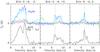 |
Fig. 2 Examples of CH3OH and H2CO spectra towards the B1b-S and B1b-N outflows. The H2CO(202 − 101) line is shown in black. The four detected CH3OH lines are shown in color: blue 30 − 20 A, cyan 3-1 − 2-1 E, green 30 − 20 E, and purple 32 − 22 E. They have been vertically shifted by 5 K for clarity. |
The line-of-sight component of the magnetic field towards Barnard 1 was determined to be B// = −27 ± 4 μG from OH Zeeman observations in a 2.9′ beam, toward a position close to IRAS 03301+3057 and ~43′′ from B1b (Goodman et al. 1989). The projected direction of the magnetic field is known from polarimetric observations of the 850 μm dust thermal emission with the JCMT at ~15′′ resolution (Matthews & Wilson 2002; Matthews et al. 2009). It presents a regular pattern with a mean N-S orientation at PA = 1° ± 19°. Hence we conclude that the magnetic field lies in the vertical plane containing the line of sight and the declination axis, its exact orientation depending on the relative strengths of its parallel and perpendicular components. Therefore, the outflows associated with B1b-N and B1b-S are not aligned with the magnetic field, but present a significant angle with its mean direction. Using the available constraints on the orientation (position angle, and for B1b-S, inclination), and assuming that the component of the magnetic field in the plane of the sky lies between 19 μG as derived by Matthews & Wilson (2002) and 100 μG, we constrained the angle β between each outflow and the magnetic field1 to be β> 36° for B1b-N and β> 29° for B1b-S. As shown in MHD simulations (Ciardi & Hennebelle 2010), significant asymmetries are predicted between the red and blue lobes at such high inclinations, which may explain the shape of B1b-N and B1b-S outflows.
Physical parameters derived from the CH3OH emission.
Physical properties of the molecular outflows.
3.2. Physical properties of the outflows
We extracted spectra of the four detected CH3OH lines at selected positions given in Table 2 and fitted these profiles with a two-component Gaussian, assuming the same velocity profile for all CH3OH lines. The narrow component centered near 6.5 km s-1 traces the quiescent component, while the broad component describes the molecular outflow. The line intensities were compared with predictions from the non-LTE radiative transfer code MADEX (Cernicharo 2012) using collision cross-sections from Rabli & Flower (2010) to derive n(H2), TK and CH3OH column densities N in the broad component. The uncertainties are 5–10 K for TK, ~50% for n(H2), and ~20% for N, as shown by the scatter at nearby positions. Because the outflows show structures down to the beam size in the integrated intensity maps (Fig.1), we assumed that the length along the line of sight for the high-velocity gas is equal to the beam size, 2.3′′ or 530 AU, to derive a lower limit to the H2 column density. This assumption led to CH3OH abundances relative to H2 in the 10-8 − 10-7 range, which are intermediate between the high values, ~10-5, reached in chemically-rich outflows (Bachiller & Pérez Gutiérrez 1997) and the low values measured in quiescent gas, ~10-10 (Guzmán et al. 2013). The H2 densities derived from MADEX range from 3 × 10⁵ to 9 × 105 cm-3. They are comparable with the densities in the B1b envelope determined from the dust continuum emission by Daniel et al. (2013). Although higher than the kinetic temperature of the quiescent gas, 12 K (Lis et al. 2010), the kinetic temperatures in the shocked gas remain moderate, between 20 and 70 K.
Using the average properties adapted to each outflow, [CH3OH] = 7 × 10⁻⁸ in B1b-S, and 10-8 for B1b-N, we computed the mass in each lobe of the outflowing gas by integrating the emission in the velocity intervals listed in Table 3. The resulting values are displayed in Table 3, together with other parameters. The outflow masses agree within a factor of two with the previous determinations based on CO(2–1) (Hirano & Liu 2014), except for the blue lobe of the B1b-S outflow, where the CO emission is optically thick. The better sensitivity and angular resolution allow us to obtain lower values for the dynamical time and outflow size, resulting in higher figures for the momentum and momentum flux by a factor of ≈5. The mechanical luminosities are at least a factor of ten lower than the bolometric luminosity of each source.
3.3. Evolutionary stage of B1b-N and B1b
B1b-N and B1b-S are located to the right of the class 0 YSOs in the diagram of normalized momentum flux, Fc/L versus normalized envelope mass Menv/L0.6 (Bontemps et al. 1996), with higher normalized envelope masses (>1.1 and >0.7) and a fairly similar normalized momentum flux (800 and 1600). Their luminosities are significantly lower than predicted by the scaling with either the envelope mass or the momentum flux, however; this is a typical feature of VeLLOs. B1b-N and B1b-S lie in fairly massive cores with at least 0.36 M⊙ in 250 AU (Hirano & Liu 2014). With such a mass reservoir, the final object is most likely a low-mass star.
Previous theoretical studies have shown that the degree of turbulence, characterized by the ratio of kinetic to gravitational energy ϵ, and the strength of the magnetic field, characterized by the ratio of the mass to flux ratio, to the critical mass to flux ratio, μ2, are two key parameters for the evolution of collapsing cores (e.g. Joos et al. 2012; Commerçon et al. 2012a). Using the density profile and turbulent line width determined by Daniel et al. (2013) in B1b, we derive ϵ ~ 0.3 and μ = 2 − 7 depending on the strength of the magnetic field. The physical parameters of the B1b-N outflow listed in Table 3 agree very well with those of the low outflow component in numerical models of the early evolution of protostars (Joos et al. 2012, 2013; Machida 2014), especially for highly magnetized cores. The significant degree of turbulence could explain the misalignment with the magnetic field. As explained by Joos et al. (2013), the localized rotational motions induced by turbulence lead to a preferred orientation for the collapsing core that is not related with the local direction of the magnetic field. It could also explain the different orientation of the B1b-N and B1b-S outflows. Models discussed by Commerçon et al. (2012a) predicted the mass within 250 AU to be M250 AU = 0.16 M⊙ for a total core mass of about 1 M⊙ within 4000 AU. These figures are compatible with the total mass of B1b, ~2.5 M⊙ (Daniel et al. 2013) and the mass of the compact mm sources, 0.36 M⊙ each. The outflow masses, velocities, and mechanical luminosities predicted by the MHD models depend on μ, with Mout = 3.3 × 10⁻³M⊙, Vmax = 4.7 km s-1, Lmech = 4.1 × 10⁻³L⊙ for μ = 2. For μ = 10, the outflow mass increases to Mout = 2. × 10-2M⊙, the luminosity to Lmech = 7 × 10⁻³L⊙, while the maximum velocity decreases to Vmax = 1.7 km s-1. These figures are computed about 1000 years after the formation of the FHSC. The agreement of the μ = 2 case with the properties derived for B1b-N, including its short dynamical age, compact size, and cold SED, is excellent, supporting its early evolutionary stage. As already discussed by Hirano & Liu (2014), the more energetic outflow properties, higher luminosity, and warmer SED of B1b-S only poorly fit with the same models, providing further support for the classification of B1b-S as a class 0 YSO, currently in a low accretion stage.
All data so far are consistent with the classification of B1b-N as an FHSC, but do not provide definitive evidence. Higher angular resolution observations are necessary to probe the gas dynamics at the ≲100 AU scale, and a more complete characterization of the chemical and physical properties of B1b is required as well.
Online material
Appendix A: Data processing
Appendix A.1: Interferometric data
We used the standard algorithms implemented in the software GILDAS/CLIC to calibrate the PdBI data. The radio-frequency bandpass was calibrated by observing the bright (12.8 Jy) quasar 3C 84. Phase and amplitude temporal variations where calibrated by fitting spline polynomials through regular measurements of two nearby (<11°) quasars (3C 84 and 0333+321). The PdBI secondary flux calibrator MWC 349 was observed once during every track, which allowed us to derive the flux scale of the interferometric data. The absolute flux accuracy is ~10%.
To produce the continuum maps, we imaged and deconvolved the WIDEX data at 2 MHz resolution. This allowed us to identify all the detected lines and to remove them before synthesizing the continuum image. To subtract the continuum from the lines, we first synthesized continuum uv tables in a ~400 MHz frequency range devoid of lines close to the targeted line. This way, we did not need to take a potential variation of the continuum level with frequency into account.
Appendix A.2: Single-dish data
Data reduction was carried out using the software GILDAS/CLASS3. The data were first calibrated to the  scale using the chopper-wheel method (Penzias & Burrus 1973). The spectra were converted to main-beam temperatures (Tmb) using the forward and main-beam efficiencies (Feff and Beff) listed in Table 1. The resulting amplitude accuracy is 10%. A 20 MHz-wide subset of the spectra was first extracted around each line rest frequency. We computed the experimental noise after subtracting a first-order baseline from every spectrum, excluding the velocity range from 4 to 9 km s-1 LSR where the signal resides. A systematic comparison of this noise value with the theoretical noise computed from the system temperature, the integration time, and the channel width allowed us to filter out outlier spectra (typically 3% of the data). The spectra were then gridded into a data cube through a convolution with a Gaussian kernel of FWHM ~ 1/3 of the IRAM-30 m telescope beamwidth.
Appendix A.3: Joint imaging and deconvolution of the interferometric and single-dish data
Following Rodriguez-Fernandez et al. (2008), the software GILDAS/MAPPING and the single-dish map from the IRAM-30 m were used to create the short-spacing visibilities not sampled by the Plateau de Bure interferometer. In short, the maps were deconvolved from the IRAM-30 m beam in the Fourier plane before multiplication by the PdBI primary beam in the image plane. After a last Fourier transform, pseudo-visibilities were sampled between 0 and 15 m, which is the difference between the diameters of the IRAM-30 m and the PdBI antennas.
These visibilities were then merged with the interferometric observations. Each mosaic field was imaged and a dirty mosaic was built by combining these fields in the following optimal way in terms of signal-to-noise ratio (Pety & Rodríguez-Fernández 2010). The dirty intensity distribution was corrected for primary beam attenuation, which induces a spatially inhomogeneous noise level. In particular, noise strongly increases near the edges of the field of view. To limit this effect, both the primary beams and the resulting dirty mosaics were truncated. The standard level of truncation was set at 20% of the maximum in GILDAS/MAPPING. The dirty image was deconvolved using the standard Högbom CLEAN algorithm. The resulting data cube was then scaled from Jy/beam to the Tmb temperature scale using the synthesized beam size (see Table 1).
The H2CO emission covers most of the mosaic field of view. The emission structure thus seems to sit on a constant brightness that only depends on the frequency, not on the spatial position. CLEAN deconvolution methods have many difficulties to properly deconvolve this “constant” emission. To avoid this, we subtracted the mean spectrum over this field of view of the single-dish data before processing them to produce the short-spacings. We then imaged and deconvolved the hybrid data set as explained above and added this mean spectrum back to the hybrid synthesis data cube (30 m + PdBI) after deconvolution and conversion to the Tmb temperature scale. This treatment is correct because a constant emission is always resolved, that is, independent of the resolving power of the observatory.
Appendix B: Spectral energy distribution
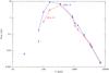 |
Fig. B.1 Spectral energy distribution of B1b-S (blue) and B1b-N (red). The data points are taken from Hirano & Liu (2014) and include Spitzer, Herschel, and ground-based observations. The stars show the new PdBI measurements. |
We present in Fig. B.1 the SED of B1b-N and B1b-S and provide refined positions in Table B.1. The measured continuum fluxes agree well with the values reported by Pezzuto et al. (2012) and Hirano & Liu (2014). It is interesting to observe that B1b-S is more luminous than B1b-N at far-infrared and submillimeter wavelengths while the reverse is true long-ward of ~2.5 mm. The new PdBI data help to locate the crossing point of the SEDs.
Positions and fluxes of the protostellar sources.
The outflow orientation is defined by its projected axis position angle PA and inclination i. β can be obtained using  .
.
 with
with  .
.
See http://www.iram.fr/IRAMFR/GILDAS for more information about the GILDAS softwares (Pety 2005).
Acknowledgments
We thank A. Ciardi, P. Hennebelle and D. Lis for illuminating discussions, and the referee for a careful review of the manuscript. This work was supported by the CNRS program “Physique et Chimie du Milieu Interstellaire” (PCMI). We thank the Spanish MINECO for funding support through grants AYA2009-07304, AYA2012-32032, FIS2012-32096 and the CONSOLIDER program “ASTROMOL” CSD2009-00038. The research leading to these results has received funding from the European Research Council under the European Union’s Seventh Framework Programme (FP/2007–2013)/ERC-2013-SyG, Grant Agreement No. 610256 NANOCOSMOS. B.C. aknowledges support by French ANR Retour Postdoc program.
References
- Bachiller, R., & Pérez Gutiérrez, M. 1997, ApJ, 487, L93 [NASA ADS] [CrossRef] [Google Scholar]
- Bontemps, S., Andre, P., Terebey, S., & Cabrit, S. 1996, A&A, 311, 858 [NASA ADS] [Google Scholar]
- Boogert, A. C. A., Pontoppidan, K. M., Knez, C., et al. 2008, ApJ, 678, 985 [NASA ADS] [CrossRef] [Google Scholar]
- Cernicharo, J. 2012, in EAS Pub. Ser. 58, eds. C. Stehlé, C. Joblin, & L. d’Hendecourt, 251 [Google Scholar]
- Ciardi, A., & Hennebelle, P. 2010, MNRAS, 409, L39 [NASA ADS] [Google Scholar]
- Commerçon, B., Launhardt, R., Dullemond, C., & Henning, T. 2012a, A&A, 545, A98 [NASA ADS] [CrossRef] [EDP Sciences] [Google Scholar]
- Commerçon, B., Levrier, F., Maury, A. J., Henning, T., & Launhardt, R. 2012b, A&A, 548, A39 [NASA ADS] [CrossRef] [EDP Sciences] [Google Scholar]
- Daniel, F., Gérin, M., Roueff, E., et al. 2013, A&A, 560, A3 [NASA ADS] [CrossRef] [EDP Sciences] [Google Scholar]
- di Francesco, J., Evans, II, N. J., Caselli, P., et al. 2007, Protostars and Planets V, 17 [Google Scholar]
- Dunham, M. M., Chen, X., Arce, H. G., et al. 2011, ApJ, 742, 1 [NASA ADS] [CrossRef] [Google Scholar]
- Evans, II, N. J., Dunham, M. M., Jørgensen, J. K., et al. 2009, ApJS, 181, 321 [NASA ADS] [CrossRef] [Google Scholar]
- Goodman, A. A., Crutcher, R. M., Heiles, C., Myers, P. C., & Troland, T. H. 1989, ApJ, 338, L61 [NASA ADS] [CrossRef] [Google Scholar]
- Guzmán, V. V., Goicoechea, J. R., Pety, J., et al. 2013, A&A, 560, A73 [NASA ADS] [CrossRef] [EDP Sciences] [Google Scholar]
- Hatchell, J., Fuller, G. A., & Richer, J. S. 2007, A&A, 472, 187 [NASA ADS] [CrossRef] [EDP Sciences] [Google Scholar]
- Hennebelle, P., & Fromang, S. 2008, A&A, 477, 9 [NASA ADS] [CrossRef] [EDP Sciences] [Google Scholar]
- Hirano, N., & Liu, F.-C. 2014, ApJ, 789, 50 [NASA ADS] [CrossRef] [Google Scholar]
- Joos, M., Hennebelle, P., & Ciardi, A. 2012, A&A, 543, A128 [NASA ADS] [CrossRef] [EDP Sciences] [Google Scholar]
- Joos, M., Hennebelle, P., Ciardi, A., & Fromang, S. 2013, A&A, 554, A17 [NASA ADS] [CrossRef] [EDP Sciences] [Google Scholar]
- Jørgensen, J. K., Harvey, P. M., Evans, II, N. J., et al. 2006, ApJ, 645, 1246 [NASA ADS] [CrossRef] [Google Scholar]
- Larson, R. B. 1969, MNRAS, 145, 271 [NASA ADS] [CrossRef] [Google Scholar]
- Lis, D. C., Wootten, A., Gerin, M., & Roueff, E. 2010, ApJ, 710, L49 [NASA ADS] [CrossRef] [Google Scholar]
- Machida, M. N. 2014, ApJ, 796, L17 [NASA ADS] [CrossRef] [Google Scholar]
- Matthews, B. C., & Wilson, C. D. 2002, ApJ, 574, 822 [NASA ADS] [CrossRef] [Google Scholar]
- Matthews, B. C., McPhee, C. A., Fissel, L. M., & Curran, R. L. 2009, ApJS, 182, 143 [NASA ADS] [CrossRef] [Google Scholar]
- Öberg, K. I., Bottinelli, S., Jørgensen, J. K., & van Dishoeck, E. F. 2010, ApJ, 716, 825 [NASA ADS] [CrossRef] [Google Scholar]
- Penzias, A. A., & Burrus, C. A. 1973, ARA&A, 11, 51 [NASA ADS] [CrossRef] [Google Scholar]
- Pety, J. 2005, in SF2A-2005: Semaine de l’Astrophysique Française, eds. F. Casoli, T. Contini, J. M. Hameury, & L. Pagani, 721 [Google Scholar]
- Pety, J., & Rodríguez-Fernández, N. 2010, A&A, 517, A12 [NASA ADS] [CrossRef] [EDP Sciences] [Google Scholar]
- Pezzuto, S., Elia, D., Schisano, E., et al. 2012, A&A, 547, A54 [NASA ADS] [CrossRef] [EDP Sciences] [Google Scholar]
- Rabli, D., & Flower, D. R. 2010, MNRAS, 406, 95 [NASA ADS] [CrossRef] [Google Scholar]
- Rodriguez-Fernandez, N., Pety, J., & Gueth, F. 2008, Single-dish observation and processing to produce the short-spacing information for a millimeter interferometer, Tech. Rep., IRAM Memo 2008-2 [Google Scholar]
- Tomida, K., Machida, M. N., Saigo, K., Tomisaka, K., & Matsumoto, T. 2010, ApJ, 725, L239 [NASA ADS] [CrossRef] [Google Scholar]
All Tables
All Figures
|
Fig. 1 Left: integrated intensity (from 0 to 14 km s-1) and velocity field of the H2CO(20,2−10,1) line. Purple contours show the continuum emission at 145 GHz. The plus signs indicate the positions of B1b-N and B1b-S. The star shows the position of B1b-W. The black ellipse shows the beam size. The small panels show the centroid velocity towards B1b-N (top) and B1b-S (bottom) in km s-1. Right: integrated intensity images (from 1.5 to 12.5 km s-1) of the four CH3OH lines detected towards B1b: from left to right and top to bottom: 30−20 A, 3-1 − 2-1 E, 30−20 E and 32−22 E. The intensity scale in K km s-1 is given by the color bar on the right. Contours of the 30−20 A line are superimposed in all plots, ranging from 1 to 20 K km s-1 with a step of 3 K km s-1. Offsets are given relative to the pointing center given in Table 1. |
| In the text | |
|
Fig. 2 Examples of CH3OH and H2CO spectra towards the B1b-S and B1b-N outflows. The H2CO(202 − 101) line is shown in black. The four detected CH3OH lines are shown in color: blue 30 − 20 A, cyan 3-1 − 2-1 E, green 30 − 20 E, and purple 32 − 22 E. They have been vertically shifted by 5 K for clarity. |
| In the text | |
|
Fig. B.1 Spectral energy distribution of B1b-S (blue) and B1b-N (red). The data points are taken from Hirano & Liu (2014) and include Spitzer, Herschel, and ground-based observations. The stars show the new PdBI measurements. |
| In the text | |
Current usage metrics show cumulative count of Article Views (full-text article views including HTML views, PDF and ePub downloads, according to the available data) and Abstracts Views on Vision4Press platform.
Data correspond to usage on the plateform after 2015. The current usage metrics is available 48-96 hours after online publication and is updated daily on week days.
Initial download of the metrics may take a while.