| Issue |
A&A
Volume 527, March 2011
|
|
|---|---|---|
| Article Number | A93 | |
| Number of page(s) | 13 | |
| Section | Cosmology (including clusters of galaxies) | |
| DOI | https://doi.org/10.1051/0004-6361/201015695 | |
| Published online | 01 February 2011 | |
Probing the first galaxies with the Square Kilometer Array
1
CENTRA, Departamento de FísicaInstituto Superior Técnico,
1049-001
Lisboa,
Portugal
e-mail: This email address is being protected from spambots. You need JavaScript enabled to view it.
2
Harvard-Smithsonian Center for Astrophysics,
Cambridge,
MA
02138,
USA
3
Department of Astrophysical Sciences, Princeton
University, Princeton, NJ
08544,
USA
4
Center for Cosmology, Department of Physics and Astronomy,
University of California, Irvine, CA
92697,
USA
Received:
5
September
2010
Accepted:
26
December
2010
Abstract
Observations of anisotropies in the brightness temperature of the 21 cm line of neutral hydrogen from the period before reionization would shed light on the dawn of the first stars and galaxies. In this paper, we use large-scale semi-numerical simulations to analyse the imprint on the 21 cm signal of spatial fluctuations in the Lyman-α flux arising from the clustering of the first galaxies. We show that an experiment such as the Square Kilometer Array (SKA) can probe this signal at the onset of reionization, giving us important information about the UV emission spectra of the first stars and characterizing their host galaxies. SKA-pathfinders with ~10% of the full collecting area should be capable of making a statistical detection of the 21 cm power spectrum at redshifts z ≲ 20 (corresponding to frequencies ν ≳ 67 MHz). We then show that the SKA should be able to measure the three dimensional power spectrum as a function of the angle with the line of sight and discuss the use of the redshift space distortions as a way to separate out the different components of the 21 cm power spectrum. We demonstrate that, at least on large scales where the Lyα fluctuations are linear, they can be used as a model independent way to extract the power spectra due to these Lyα fluctuations.
Key words: cosmology: miscellaneous / large-scale structure of Universe / galaxies: high-redshift / intergalactic medium
Hubble Fellow.
© ESO, 2011
1. Introduction
The period of formation of the very first stars is one of the least understood epochs in the history of the Universe. The 21 cm spin-flip transition of neutral hydrogen at high redshifts has the potential to open a new observational window to study this early period, where the most distant, first galaxies reside, and even beyond that. Moreover, 21 cm observations may provide the only means to detect signatures of the first galaxies at z > 15 in the foreseeable future. While the James Webb Space Telescope (JWST1) will be able to detect galaxies at z ≤ 10 (e.g., Stiavelli et al. 2004), it will not image all of the sources responsible for the reionization of the Universe. If current estimates in the literature are correct, even deep fields with JWST will only detect ~30% of the sources responsible for reionization or maintaining reionization at z ~ 12 (Salvaterra et al. 2010). At z ~ 20, direct emission from stars will be below the threshold of JWST observations and new techniques will be required to probe the onset of reionization. One possibility is Lyman-α emitter surveys over the next decade, but even these surveys will only be able to detect the brightest galaxies for selected redshift ranges at z ≤ 10 (e.g., Ouchi et al. 2008; Nilsson et al. 2007; Cuby et al. 2007; Stark et al. 2007; Willis et al. 2008; McMahon et al. 2008; Hibon et al. 2010), but not the fainter, first galaxies at redshift z ≥ 20. The next generation of large ground based telescopes, like the European Extremely Large Telescope (E-ELT2), Thirty Meter Telescope (TMT3), and Giant Magellan Telescope (GMT4), will only be capable of detecting at most the very brightest galaxies at redshifts z ≈ 20. Most of the star formation however will be in fainter galaxies making it impossible for these telescopes alone to survey the full population. In combination with 21 cm observations, which are sensitive to the integrated Lyα emission of the galaxies, it should be possible to form a complete census of the first sources.
With a wide frequency coverage, observations of the 21 cm signal will provide a 3-dimensional tomographic view of the inter-galactic medium (IGM), before and during the cosmological reionization (for a review see Furlanetto et al. 2006). As soon as the first galaxies appear, at a redshift of z ~ 20−30 in the standard cold dark matter cosmological model (e.g., Komatsu et al. 2011), photons emitted at frequencies between the Lyα and Lyman limit quickly couple the spin temperature of the hyperfine level population to the IGM gas temperature through the Wouthuysen-Field effect (Wouthuysen 1952; Field 1959). Provided the IGM has been cooling adiabatically (X-ray heating is still negligible during this early stage of galaxy formation), the 21 cm signal will be strong and observed in absorption against the cosmic microwave background (CMB). Because the Lyα coupling depends on the local Lyα radiation, which is correlated with galaxies, the 21 cm signal fluctuations will trace the location, mass, emission spectra, luminosity and redshift evolution of high redshift galaxies.
Since the first galaxies represent rare high-σ peaks in the cosmic density field (e.g., Trac & Cen 2007), their spatial distribution have large fluctuations and we expect the Lyα contribution to the overall 21 cm signal to be appreciable, considerably improving the prospects for detection of the Lyα fluctuations through 21 cm observations. Although the high redshift-end of the reionization process will be inaccessible to the first generation experiments, such as the LOw Frequency ARray (LOFAR5) and the Murchison Widefield Array (MWA6), the second generation experiments such as the Square Kilometre Array (SKA7) should have enough collecting area to statistically probe the signal.
On the theoretical front, analytical models have been useful in predicting the probable evolution of the high redshift signal (Barkana & Loeb 2005b; Pritchard & Furlanetto 2007; Pritchard & Loeb 2008), but rely on linear approximations and require further comparison with simulations. Numerical simulations, on the other hand, can provide a self-consistent treatment of the Lyα radiative transfer, taking into account effects such as the scattering in the Lyα line wings (Semelin et al. 2007; Baek et al. 2009), although they are typically slow to run and are limited to small volumes (≤100 Mpc/h). Recent developments using semi-numerical algorithms have allowed the rapid generation of the high redshift 21 cm signal during the pre-reionization epoch (Santos et al. 2008, 2010; Mesinger et al. 2010) in large boxes, while maintaining the 3-d structure of the signal on large scales as seen in the full numerical simulations.
In this paper we will generate fast simulations as described in Santos et al. (2010) to analyze the dependence of the overall 21 cm signal on several parameters related to the first galaxies in the Universe and consider the ability of an experiment like SKA to constrain these parameters. The layout of this paper is as follows. We start in Section 2 by describing the 21 cm signal and the free parameters of the model that affect the Lyα fluctuations. In Sect. 3 we present the experimental setup used for SKA, calculating the expected error on the 3-d power spectrum. In Sect. 4 we study the possibility of constraining the signal in a model independent way, using the redshift-space distortions and the corresponding measurements on the 3-d power spectrum as a function of the angle with respect to the line of sight. We end with our conclusions and a discussion of the prospects for SKA in Sect. 5.
Throughout this paper where cosmological parameters are required we use the standard set of values Ωm = 0.28, ΩΛ = 0.72, Ωb = 0.046, H = 100 h km s-1 Mpc-1 (with h = 0.70), nS = 0.96, and σ8 = 0.82, consistent with the latest measurements (Komatsu et al. 2011).
2. The 21 cm signal: Lyα fluctuations
The 21 cm brightness temperature corresponds to the change in the intensity of the CMB
radiation due to absorption or emission when it travels through a patch of neutral hydrogen.
It is given, at an observed frequency ν in the direction
 ,
by (see e.g. Santos et al. 2008)
,
by (see e.g. Santos et al. 2008) ![Mathematical equation: \begin{eqnarray} \label{t21} \delta T_{\rm b}(\nu) &\approx & 23 x_{HI}(1+\delta) \left(1-\frac{T_{\gamma}}{T_{\rm S}}\right) \left( \frac{h}{0.7}\right)^{-1} \left( \frac{\Omega_{\rm b} h^2}{0.02} \right)\nonumber\\ &&\times\left[\left(\frac{0.15}{\Omega_{\rm m} h^2} \right)\left(\frac{1+z}{10}\right) \right]^{1/2}\left(\frac{1}{1+1/H\,{\rm d}v_r/{\rm d}r}\right)\ \rm{mK}, \end{eqnarray}](/articles/aa/full_html/2011/03/aa15695-10/aa15695-10-eq28.png) (1)where
xHI is the fraction of neutral hydrogen (mass weighted),
dvr/dr is the comoving
gradient of the line of sight component of the comoving velocity and we use
δa for the fractional value of the quantity
a (
(1)where
xHI is the fraction of neutral hydrogen (mass weighted),
dvr/dr is the comoving
gradient of the line of sight component of the comoving velocity and we use
δa for the fractional value of the quantity
a ( )
with δ for the fluctuation in the matter density.
)
with δ for the fluctuation in the matter density.
The spin temperature (TS) is coupled to the hydrogen gas
temperature (TK) through the spin-flip
transition, which can be excited by collisions or by the absorption of Lyα
photons (Wouthuysen-Field effect) and we can write:
 (2)where
xtot = xα + xc
is the sum of the radiative and collisional coupling parameters and we are already assuming
that the color temperature of the Lyα radiation field at the
Lyα frequency is equal to
TK. Note that although we talk here about
Lyα radiation, in effect we consider the contribution from all the
photons up to the Lyman limit frequency, since photons redshifting into Lyman series
resonances can produce Lyα photons as a result of atomic cascades (Hirata 2006; Pritchard
& Furlanetto 2006). When the coupling to the gas temperature is negligible
(e.g. xtot ~ 0),
TS ~ Tγ
and there is no signal. On the other hand, for large xtot,
TS simply follows
TK.
(2)where
xtot = xα + xc
is the sum of the radiative and collisional coupling parameters and we are already assuming
that the color temperature of the Lyα radiation field at the
Lyα frequency is equal to
TK. Note that although we talk here about
Lyα radiation, in effect we consider the contribution from all the
photons up to the Lyman limit frequency, since photons redshifting into Lyman series
resonances can produce Lyα photons as a result of atomic cascades (Hirata 2006; Pritchard
& Furlanetto 2006). When the coupling to the gas temperature is negligible
(e.g. xtot ~ 0),
TS ~ Tγ
and there is no signal. On the other hand, for large xtot,
TS simply follows
TK.
2.1. Simulations
Simulations used in the analysis.
We use the code SimFast218 described in Santos et al. (2010) to calculate the spin temperature and the corresponding 21 cm signal. The code starts by calculating the linear density field in a box followed by the corresponding halo and velocity fields. Then, it computes the nonlinear density and halo fields, the collapsed mass distribution, the corresponding star formation rate, the IGM gas temperature, the Lyα coupling, the collisional coupling and finally the 21 cm brightness temperature accounting for all the contributions including the correction due to redshift space distortions using the nonlinear velocity field. In order to probe the full range of k space, we generated two end to end simulations using the SimFast21 code, one large simulation with 1Gpc in size and 1.6 Mpc resolution (S1) and another with higher resolution (0.186 Mpc) but smaller 143 Mpc in size (simulation S2). This code has the advantage of being modular, allowing to replace some of the steps by simulation boxes generated by other techniques. Therefore, for comparison, we also applied our Lyα calculation to the output (star formation rate, matter density) from the Trac et al. (2008) simulation, thus providing a check of the approximation used to generate the halo mass function. We call this simulation of the 21 cm signal, S3, with a size of 143 Mpc and a resolution of 0.186 Mpc. Table 1 shows a summary of the simulations used. All simulations use halos with masses down to 108 M⊙ corresponding to a minimum virial temperature of T ~ 104 K. Simulation S1 cannot resolve halos down to these mass scales and we populate the remaining halos in each (empty) cell using a Poisson sampling biased with the underlying density field, giving a mass function consistent with N-body simulations once non-linear corrections are applied, as described in Santos et al. (2010). With the new version of the code, we also allow a hybrid approach instead of the “Poisson” method, where, after the halo finding algorithm, we calculate the unresolved collapsed mass in each empty cell using the collapsed fraction fcoll from the extended Press-Schechter formula (see e.g. Zahn et al. 2007). This is fine as long as we do not want to resolve halos within a cell. Note that this is used at the cell level, allowing to also apply the non-linear corrections to each cell. Both approaches give similar results in terms of the 21 cm signal, although the later method can be faster as we decrease the halo minimum mass used in the simulation.
Simulation S3 was run using a hybrid simulation code in modeling cosmic reionization (Trac et al. 2008), incorporating N-body, hydrodynamic, and RT algorithms to solve the coupled evolution of the dark matter, baryons, and radiation (Trac & Pen 2004, 2006; Trac & Cen 2007). It covers a large dynamic range and satisfies the requirements of having sufficiently high resolution to capture small-scale structure, and simultaneously a sufficiently large volume to reduce sample variance (Barkana & Loeb 2004). The simulation is run in two steps. The first step involves running a high-resolution N-body simulation with 30723 dark matter particles on an effective mesh with 11 5203 cells in a comoving box, 143 Mpc on a side. We identified collapsed dark matter halos on the fly using a friends-of-friends algorithm, with a linking length b = 0.2 times the mean inter-particle spacing, in order to model radiation sources and sinks. With a particle mass resolution of 2.68 × 10⁶ h-1 M⊙, we can reliably locate all dark matter halos with virial temperatures above the atomic cooling limit (T ~ 104 K) with a minimum of ~40 particles (Heitmann et al. 2008), and half of this collapsed mass budget is resolved with >400 particles per halo. Our halo mass functions are in very good agreement with other recent work (e.g. Reed et al. 2007; Lukic et al. 2007; Cohn & White 2008). The second step produces a hydrodynamic + RT simulation with moderate resolution, but incorporating subgrid physics modeled using the high-resolution information from the large N-body simulation. Radiation sources are prescribed and star formation rates calculated using the halo model described in Trac & Cen (2007). We consider only Population II stars from starbursts (Schaerer 2003a) as contributing to the ionizing photon budget. The hydro+RT simulation utilizes equal numbers (N = 15363) of dark matter particles, gas cells, and adaptive rays, where for the latter, we track 5 frequencies above the hydrogen ionizing threshold of 13.6 eV. The photo-ionization and photo-heating rates for each cell are calculated from the incident radiation flux and used in the non-equilibrium solvers for the ionization and energy equations. The initial conditions are generated with a common white noise field and a linear transfer function calculated with CAMB (Lewis et al. 2000).
In order to calculate the Lyα coupling in a given cell, the algorithm
assumes that the scattering rate is proportional to the total Lyman series flux arriving
in that cell (see again Santos et al. 2010). This
Lyman series flux is obtained through a 3-dimensional integration of the comoving photon
emissivity, ϵ(x,ν,z) (defined
as the number of photons emitted at position x, redshift
z and frequency ν per comoving volume, per proper time
and frequency), which is assumed proportional to the star formation rate:  (3)where
SFRD(x,z) is the star formation rate density
from the simulation (in terms of the number of baryons in stars per comoving volume and
proper time). As stated above, in the simulation S3 we used the star formation rate
obtained from the Trac et al. (2008) simulation.
ϵb(ν) is the spectral distribution function
of the sources (defined as the number of photons per unit frequency emitted at
ν per baryon in stars). We assumed a power law model for
ϵb(ν):
(3)where
SFRD(x,z) is the star formation rate density
from the simulation (in terms of the number of baryons in stars per comoving volume and
proper time). As stated above, in the simulation S3 we used the star formation rate
obtained from the Trac et al. (2008) simulation.
ϵb(ν) is the spectral distribution function
of the sources (defined as the number of photons per unit frequency emitted at
ν per baryon in stars). We assumed a power law model for
ϵb(ν):
 (4)between
να(10.2 eV) and the Lyman limit frequency
(13.6 eV). This will allow us to calculate how sensitive the 21 cm power spectrum is to
changes in the parameters of the emission model.
(4)between
να(10.2 eV) and the Lyman limit frequency
(13.6 eV). This will allow us to calculate how sensitive the 21 cm power spectrum is to
changes in the parameters of the emission model.
We take α = −0.9 and A such that the integration between the Lyα and Lyman limit frequencies gives a total emission of 20 000 photons per baryon. These numbers are based on the expected PopII spectra from Schaerer (2003b). Note that the parameter A will be totally degenerate with the star formation rate efficiency in our model. Since the initial mass function (IMF) is likely to be dominated by massive stars, this single power law model is likely to be a good description of the emission spectra (see e.g. Leitherer et al. 1999), although a broken power law can sometimes provide a slightly better fit (Pritchard & Furlanetto 2006). Moreover, as we shall see later, results are very insensitive to α, essentially depending on the total number of photons emitted per baryon. We also note that the above calculation of Lyα radiation does not take into account full radiative transfer effects via their scattering off of neutral hydrogen atoms (scattering in the wings of the Lyα line, Chuzhoy & Zheng 2007; Semelin et al. 2007, could increase the amplitude of the fluctuations on small scales). As a result, we expect that some details of the signal on small scales due to Lyα coupling to be partly inaccurate.
Since the details of the galaxy emissivity depend upon the assumed initial mass function (IMF), which is poorly known (Barkana & Loeb 2001), these values are subject to considerable uncertainty. Constraints would therefore provide useful information about the properties of the first galaxies. These uncertainties make the mapping between the mean value of the Lyα coupling ⟨ xα ⟩ and redshift uncertain. We will therefore describe the shape of the Lyα power spectrum for a given ⟨ xα ⟩ and caution that the redshift at which that actually occurs may be very different from our fiducial model.
2.2. Comparison
The 21 cm signal occurs over a wide range of scales, with Lyα fluctuations contributing at wave-numbers 0.01 ≲ k/(h/ Mpc) ≲ 10. Since none of our simulations can cover this broad set of scales individually, we exploit the modularity of the code to piece together two simulations to cover the full range. To check that this gives self-consistent results, in Fig. 1 we plot the full 21 cm brightness temperature for the three simulations at a few values of the mean Lyα coupling ⟨ xα ⟩ . In each case, we take into account fluctuations from the density, velocity and Lyα terms as well as the collisional coupling, ionization fraction (although at high redshifts this is negligible) and gas temperature (note again that for simulation S3 we calculate the temperature using our semi-numerical code based on the simulation SFRD). We see a smooth transition from the S1 to the S2 simulation, showing for the first time, the full range of scales from k ~ 0.01 h/Mpc to k ~ 20 h/Mpc with an amplitude that is roughly between 100 mK2 and 1000 mK2 on the range of interest, which should help the detection of the signal. The increase in the amplitude as the coupling increases is due primarily to the cooling of the IGM gas in this redshift range, which leads to a stronger absorption signal. Note that, as explained in Santos et al. (2010), when integrating the Lyα flux, we assume the star formation rate is homogeneous above a certain large scale in order to make the calculation faster. In this paper this scale was set to 143 Mpc which is the origin of the slight break we see in Fig. 1 for xα ≳ 1. The black dash-dotted line in this figure shows the correction for xα = 0.4 if instead we did the inhomogeneous integration up to 300 Mpc. Since this is a small correction, we decided to keep the limit to 143 Mpc.
For comparison, the dashed line shows the power spectrum from simulation S3, which agrees quite well with results using the semi-numerical code validating our halo/star formation prescription (although in S3 there is a decrease of the signal on very small scales, which is related to a smoothing of the velocity term on these scales). An extensive comparison made by Baek et al. (2010) using radiative transfer simulations (although for smaller box size ~100 Mpc/h and lower mass resolution ≳ 1010 M⊙) shows a similar spectrum for models in the same parameter range.
 |
Fig. 1 The 21 cm brightness temperature with all fluctuations included. Dotted – simulation S1, solid – simulation S2, dashed – simulation S3. Redshifts from top to bottom are: 19.25 (⟨ xα ⟩ = 0.9), 20.25 (⟨ xα ⟩ = 0.4), 22.5 (⟨ xα ⟩ = 0.06). The black dash-dotted line shows the correction for ⟨ xα ⟩ = 0.4 when doing the full Lyα flux inhomogeneous integration. |
Since it will be the focus of the present paper, we now examine the Lyα
fluctuations in more detail. In Fig. 2 we show the
power spectrum of the quantity  for the three simulations at four different values of
⟨ xα ⟩ .
Aα represents the contribution of the
Lyα coupling to the 21 cm signal and varies between 0 and 1. Note that
the xα field tends to be dominated by the
large values close to individual sources, which obscures the details of the coupling since
in these regions Aα saturates. The amplitude
of the power spectrum principally depends on
⟨ xα ⟩ with the fluctuations peaking at
⟨ xα ⟩ ~ 0.5, suggesting that
this is the regime to best extract information related to the Wouthuysen-Field effect
(z ~ 20 in our model), and we will concentrate on these
redshifts from now on. Figure 2 shows again the
correction to the calculation if we do not impose a limit to the Lyα
inhomogeneous integration (top, cyan dashed line, for
xα = 0.9). This correction will be more
evident as xα increases (see the “break” for
xα = 8.4) but at the same time the
contribution to the overall 21 cm signal will become smaller so that it should be safe to
neglect this correction.
for the three simulations at four different values of
⟨ xα ⟩ .
Aα represents the contribution of the
Lyα coupling to the 21 cm signal and varies between 0 and 1. Note that
the xα field tends to be dominated by the
large values close to individual sources, which obscures the details of the coupling since
in these regions Aα saturates. The amplitude
of the power spectrum principally depends on
⟨ xα ⟩ with the fluctuations peaking at
⟨ xα ⟩ ~ 0.5, suggesting that
this is the regime to best extract information related to the Wouthuysen-Field effect
(z ~ 20 in our model), and we will concentrate on these
redshifts from now on. Figure 2 shows again the
correction to the calculation if we do not impose a limit to the Lyα
inhomogeneous integration (top, cyan dashed line, for
xα = 0.9). This correction will be more
evident as xα increases (see the “break” for
xα = 8.4) but at the same time the
contribution to the overall 21 cm signal will become smaller so that it should be safe to
neglect this correction.
Comparing to Fig. 14 in Baek et al. (2009) we see that the fluctuation level is similar, although we do not see their small scale increase in power due to point sources for k > 1 Mpc/h. The difference on small scales (k > 1 Mpc/h) between our results and those of (Baek et al. 2009) is, at least in part, likely due to lack of Lyα radiative transfer treatment in ours (although differences in size and mass resolution of the simulations should also be considered). As will become clear later, it is the 21 cm observations at large scales that offer the best means to extract Lyα physics, so the inaccuracies at small scales do not pose a significant problem.
The full N-body simulation (S3) agrees reasonable well with our calculation and again we see a smooth transition from the very large scale simulation to the high resolution one, giving us a complete view over all scales of the expected signal. Although it is clear that there is room for more detailed numerical work on the 21 cm signal, these comparisons give us confidence in the semi-analytic simulation and we now turn to exploring the consequences for observations.
 |
Fig. 2 Power spectrum of
|

2.3. Identifying the Lyα epoch
In principle, there are several contributions to the 21 cm brightness temperature and full modeling of the signal would be required to disentangle the part due to Lyα fluctuations and obtain parameter constraints on the first galaxies. However, as we can see from Figs. 3 and 4, both the fluctuations in the collisional coupling and in the gas temperature should be subdominant at the redshifts where the Lyα fluctuations are strongest (when ⟨ xα ⟩ < 1 and k < 1 h/ Mpc) making the analysis of the signal more straightforward (the ionization is very small at these redshifts, so that their contribution to the fluctuation power is completely negligible). The fluctuations in the gas temperature shown in Fig. 4 only include the heating due to x-rays, which can potentially be harder to separate from the Lyα fluctuations. On top of this we also have fluctuations in the gas temperature due to the adiabatic cooling process which are essentially proportional to the matter density perturbations. Both contributions are intrinsically included in the simulation, although, as we see, the effect from x-ray heating is negligible.
 |
Fig. 3 The average xα and xc coupling parameters as a function of redshift for the S2 simulation. The Lyα coupling dominates over collisions at all redshifts considered. |
 |
Fig. 4 The fluctuations from Lyα ,
Aα (solid) and the gas temperature,
|

The question then is if whether we can actually identify this epoch from observations rather than theoretical guesses. In many models, the global (average) 21 cm signal clearly shows the transition from Lyα coupling to X-ray heating and finally to emission once the gas is heated above the CMB temperature (Pritchard & Loeb 2010). This average signal will not be accessible to interferometers, but as was shown in Santos et al. (2008), Fig. 9, the large scale 21 cm power spectrum can also depict the evolution of the signal.
The rms of the signal (⟨ (δTb − ⟨ δTb ⟩ )2 ⟩ ) can also provide that information and should be easier to measure with interferometers. As we can see in Fig. 5, at z > 25 the signal is initially small since coupling to the gas temperature is low. As the Lyα coupling increases, the spin temperature approaches the gas temperature and the rms of the signal increases, not only due to fluctuations on the Lyα field but also because the factor Aα(1 − Tγ/TK) is increasing (in absolute terms) since the gas is still cooling adiabatically. Once the gas temperature begins to increase due to X-ray heating the signal decreases and we see the turning point at z ~ 16 (the transition from absorption to emission occurs later at z ~ 13. Finally, the gas is heated far above the CMB temperature and the signal plateaus until reionization finally causes it to die away at z ~ 7.
 |
Fig. 5
|

Note that as X-rays start heating the IGM, the signal does not drop immediately since this heating is inhomogeneous and there will be some region still cooling adiabatically as well as temperature fluctuations contributing to the rms. Therefore we see a small plateau at the peak of the signal starting at z ~ 19. The conclusion is that it should be safe to neglect the contributions of the X-ray heating to the 21 cm signal between the points when the rms (or the average) starts rising at z ≳ 24 and before we reach the plateau at the maximum z ≲ 19 (xα ~ 0.9), at least on large scales where the Lyα contribution dominates over the temperature as we can see in Fig. 4.
In this case, the equation simplifies and we can write the full 21 cm signal as:
 (5)where
 (note the different definition from Barkana & Loeb
2005b), corresponding to the adiabatic cooling process
(TK ∝ ρ2/3)
and
(note the different definition from Barkana & Loeb
2005b), corresponding to the adiabatic cooling process
(TK ∝ ρ2/3)
and  K. Also,
![Mathematical equation: \begin{eqnarray} C(z) &\approx& 23 \left( \frac{0.7}{h}\right)\left( \frac{\Omega_{\rm b} h^2}{0.02} \right) \left[\left(\frac{0.15}{\Omega_{\rm m} h^2} \right)\left(\frac{1+z}{10}\right)\right]^{1/2}\\ \nonumber && \times \langle 1-\frac{T_{\gamma}}{T_K} \rangle \langle A_{\alpha} \rangle \langle A_v \rangle\ \ \rm{mK} \end{eqnarray}](/articles/aa/full_html/2011/03/aa15695-10/aa15695-10-eq110.png) (6)with
(6)with
 (⟨ Av ⟩ ~ 1). Figure 6 shows the contribution to the full 21 cm signal from
each of the terms considered on Eq. (5)
using simulations S1 and S2. Again we see that the Lyα term dominates
over large scales k < 1 h/Mpc, which makes it all important to
be able to generate large volume simulations (>100 Mpc/h) and give us confidence
that it should be possible to extract the Lyα signal over the redshift
range proposed without confusion from other contributions. Moreover, the small
contribution at these scales from the other terms in Eq. (5) can be modeled with reasonable accuracy if we know the matter power
spectrum.
(⟨ Av ⟩ ~ 1). Figure 6 shows the contribution to the full 21 cm signal from
each of the terms considered on Eq. (5)
using simulations S1 and S2. Again we see that the Lyα term dominates
over large scales k < 1 h/Mpc, which makes it all important to
be able to generate large volume simulations (>100 Mpc/h) and give us confidence
that it should be possible to extract the Lyα signal over the redshift
range proposed without confusion from other contributions. Moreover, the small
contribution at these scales from the other terms in Eq. (5) can be modeled with reasonable accuracy if we know the matter power
spectrum.
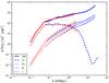 |
Fig. 6 The 21 cm power spectrum and its main contributions at ⟨ xα ⟩ = 0.4 (z ~ 20.25) using simulation S1 (red) and simulation S2 (blue). Top solid lines – all contributions included; dashed – Lyα only; dotted – matter density; bottom thin solid lines – fluctuations on the gas temperature from adiabatic cooling only; dot-dashed – velocity fluctuations only. |
3. Measurements with the SKA
In this section, we outline details related to the experimental measurement of the 21 cm signal at the very high redshifts during the epoch where Lyα dominates.
3.1. Noise power spectrum
Before we go into the details of the experimental setup, we quickly review the noise
calculation that goes into our analysis. Following Bowman
et al. (2006); Mao et al. (2008); McQuinn et al. (2006), the expected error
ΔP(k,θ) on the measurement of the 3-d power spectrum
of the signal PS(k,θ) with noise
PN(k,θ) is given by
![Mathematical equation: \begin{equation} \Delta P(k,\theta) = \frac{1}{\sqrt{N_{\rm m}(k,\theta)}}\left[P_{\rm S}(k,\theta)+P_N(k,\theta)\right] , \label{pk_error} \end{equation}](/articles/aa/full_html/2011/03/aa15695-10/aa15695-10-eq119.png) (7)where we are
assuming that the power spectrum depends only on the moduli (k) of the
vector k and on the angle θ between
k and the line of sight.
Nm(k,θ) is the total number of modes in
k space contributing to the measurement (note that the
sum is only done over half the sphere). In order to obtain the above expression, we “grid”
the k space into pixels of size
d
(7)where we are
assuming that the power spectrum depends only on the moduli (k) of the
vector k and on the angle θ between
k and the line of sight.
Nm(k,θ) is the total number of modes in
k space contributing to the measurement (note that the
sum is only done over half the sphere). In order to obtain the above expression, we “grid”
the k space into pixels of size
d , where ⊥
denotes the component perpendicular to the line of sight and ∥ the parallel one and
assume that measurements in different pixels are uncorrelated. The size of these pixels is
just determined by the real space volume of the observed region:
, where ⊥
denotes the component perpendicular to the line of sight and ∥ the parallel one and
assume that measurements in different pixels are uncorrelated. The size of these pixels is
just determined by the real space volume of the observed region:
 (8)where
AFoV is the field of view of the experiment (in radians),
B is the bandwidth for this particular measurement,
(8)where
AFoV is the field of view of the experiment (in radians),
B is the bandwidth for this particular measurement,
 is the comoving
distance to redshift z and
y ≡ λ21(1 + z)2/H(z)
is a conversion factor between frequency intervals and comoving distances
(H(z) is the Hubble expansion rate and
λ21 ≈ 21.1 cm the rest frame wavelength of the 21 cm line).
We can relate dk ⊥ to the resolution in the
u − v (visibility) space, du (the
Fourier dual of the angular coordinates on the sky) by
dk ⊥ = 2πdu/r
(using our Fourier conventions). Note that
is the comoving
distance to redshift z and
y ≡ λ21(1 + z)2/H(z)
is a conversion factor between frequency intervals and comoving distances
(H(z) is the Hubble expansion rate and
λ21 ≈ 21.1 cm the rest frame wavelength of the 21 cm line).
We can relate dk ⊥ to the resolution in the
u − v (visibility) space, du (the
Fourier dual of the angular coordinates on the sky) by
dk ⊥ = 2πdu/r
(using our Fourier conventions). Note that
 (9)and
is related to the effective collecting area of one element of the interferometer,
Ae = λ2du2,
where λ is the wavelength of observation (but care must be taken in this
relation due to multi-beaming). The resolution along the line of sight is just
dk ∥ = 2π/(yB) (visibilities are Fourier
transformed along the frequency coordinate).
(9)and
is related to the effective collecting area of one element of the interferometer,
Ae = λ2du2,
where λ is the wavelength of observation (but care must be taken in this
relation due to multi-beaming). The resolution along the line of sight is just
dk ∥ = 2π/(yB) (visibilities are Fourier
transformed along the frequency coordinate).
Finally, the noise power spectrum is given by
 (10)where
t(k,θ) is the time spent observing a given
k pixel which is just the time spent observing the
corresponding pixel of resolution du2 on the
u − v plane,
u = rk ⊥ /(2π).
For a total observation time, t0, this will be related to the
baseline density distribution, n(|u|),
through
t(k,θ) = t0du2n(|u|) = t0du2n(rksin(θ)/(2π))
assuming the baseline density is rotationally invariant (which is a good approximation due
to Earth rotation). If we make the further assumption that the baseline density
distribution is constant on the u − v plane up to a
maximum baseline Dmax (which is not the same as assuming an
uniform distribution of antennas), we have
(10)where
t(k,θ) is the time spent observing a given
k pixel which is just the time spent observing the
corresponding pixel of resolution du2 on the
u − v plane,
u = rk ⊥ /(2π).
For a total observation time, t0, this will be related to the
baseline density distribution, n(|u|),
through
t(k,θ) = t0du2n(|u|) = t0du2n(rksin(θ)/(2π))
assuming the baseline density is rotationally invariant (which is a good approximation due
to Earth rotation). If we make the further assumption that the baseline density
distribution is constant on the u − v plane up to a
maximum baseline Dmax (which is not the same as assuming an
uniform distribution of antennas), we have
 (11)noting that the
integration over half the plane should give approximately
(11)noting that the
integration over half the plane should give approximately
 (Na is the number of elements in the
interferometer). The noise power spectrum then further simplifies to:
(Na is the number of elements in the
interferometer). The noise power spectrum then further simplifies to:
 (12)where
Atot is the total collecting area of the telescope. The
system temperature was modeled by
(12)where
Atot is the total collecting area of the telescope. The
system temperature was modeled by  (13)where the first
term is the receiver noise temperature (assumed to be 50 K) and the second term is the
much larger sky temperature which is dominated by the Galactic Synchrotron at the
redshifts of interest. Note in particular that neither the bandwidth or the frequency
resolution show up in the noise calculation (they can be used instead to increase the
number of modes Nm available to reduce the total error).
Moreover, looking at the last expression we see that
PN decrease as
(13)where the first
term is the receiver noise temperature (assumed to be 50 K) and the second term is the
much larger sky temperature which is dominated by the Galactic Synchrotron at the
redshifts of interest. Note in particular that neither the bandwidth or the frequency
resolution show up in the noise calculation (they can be used instead to increase the
number of modes Nm available to reduce the total error).
Moreover, looking at the last expression we see that
PN decrease as
 once we fix
t0 and the maximum baseline. Once we achieve
PS ~ PN
the only way to decrease the total error is through Nm which
does not depend on the total collecting area or the baseline distribution.
once we fix
t0 and the maximum baseline. Once we achieve
PS ~ PN
the only way to decrease the total error is through Nm which
does not depend on the total collecting area or the baseline distribution.
3.2. Experimental setup
The current generation of radio-interferometers now in construction such as the MWA and LOFAR will not have the collecting area necessary to probe the high redshift universe (z > 15). This will require a second generation experiment such as the SKA, with an observational window between 70 MHz and 10 GHz and planned to be completed by 2020. The SKA will probably be made up of three different instruments (Schilizzi et al. 2007; Faulkner 2010): SKA-low, tailored for the low frequency signal between 70MHz to 450MHz, probably made up of sparse Aperture Arrays so that the collecting area scales as λ2; SKA-mid between 400 MHz and 1.4 GHz, using dense Aperture Arrays; and SKA-high, using dishes for frequencies above 1.2 GHz (note the small overlap between ranges). In this paper, we will assume a low frequency “SKA type” experiment with a setup capable of probing the high redshift, pre-reionization epoch.
The analysis in the previous Section showed that in order to measure the imprint of the first galaxies on the 21 cm signal, we need to observe at least up to z = 20, corresponding to a frequency of ν ~ 68 MHz. Allowing for some flexibility, we consider an experiment that would be able to measure frequencies down to 60 MHz. Taking into account the design reference for SKA, we assumed a sensitivity of 4000 m2/K at 70 MHz (which in fact requires a total collecting area of ~14 km2, well above the 1 km2 used to baptize the telescope) and scaling as λ2 around these frequencies. Note that the planned collecting area has been subject to some change along the years and the current design for what is called SKA Phase 1 suggests a sensitivity of 2000 m2/K instead (Garrett et al. 2010). In order to allow for designs with lower sensitivities, we also consider instruments with 20% and 10% of the total collecting area of the design reference SKA. For the distribution of antennas, the SKADS9 reference design assumes they would be collected in 250 stations of 180 m diameter each, with 66% in a 5 km diameter core and the rest along 5 spiral arms out to a 180 km radius.
The signal we are looking for dominates on scales k ≲ 1 h/Mpc, requiring baselines up to ~10 km for proper sampling at the relevant frequencies, e.g. a resolution of 0.76 arcmin at z = 20 (kmax ⊥ ~ 1.8 h/Mpc – higher resolution can be achieved along the frequency direction although the error would be much larger since we would only have modes along the line of sight). Taking a reasonable setup, we assumed that 70% of the total collecting area would be concentrated within this core of 10 km in diameter. We do not use the rest of the collecting area in the noise calculation, assuming instead this would be used for point source removal and calibration. The same applies when the total collecting area is only 10% and 20% of the reference design.
For the field of view (FoV) we used 10 × 10 deg2, which, taking z = 20 as reference, sets a resolution of roughly dk ⊥ ~ 4.5 × 10⁻³ h/Mpc. Note that the FoV can be traded with the number of beams (in case we want to observe separate fields) and the total instantaneous bandwidth (in case we want to probe a larger redshift range). Assuming that, in the core, correlations within stations are also possible, we considered a minimum baseline of 50 m giving kmin ⊥ ~ 9 × 10⁻³ h/Mpc which is enough to probe the scales of interest. The frequency interval for the analysis should be chosen carefully at these frequencies since for a fixed frequency interval, dz increases with redshift. For instance, an interval of 8 MHz used in previous analysis (e.g. Bowman et al. 2007) corresponds to integrating the signal over dz ~ 2.5 which will average out important features during the period when Lyα fluctuations are important. On the other hand, using a small interval means we will have fewer modes along the line of sight. Taking a compromise, we assumed that each measurement was done with an interval of 4 MHz and a resolution of 0.01 MHz, giving dk ∥ = 0.08 h/Mpc and kmax ∥ = 16.6 h/Mpc. Note that the total instantaneous bandwidth should be much larger than this (~50 MHz), so we can measure several redshifts at the same time. Finally, the total integration time was taken to be 1000 h (see Table 2 for a summary of the experimental setup).
Assumed experimental setup.
We followed the error calculation described above for the power spectrum assuming a distribution for the antenna/stations of the telescope such that a constant baseline density is obtained. Although this is difficult to achieve in practice since the density of stations normally decreases from the center, it turns out that this configuration gives the best signal to noise in terms of the brightness temperature maps and it should therefore give a good indication of the telescope capabilities to probe the 21 cm signal power spectrum. A final note on foregrounds: they can be the most damaging factor at these low frequencies (together with the calibration issues raised by the ionosphere) although it is expected that if the foregrounds are smooth enough along the frequency direction, they can be simply removed by fitting out a smooth function (Jelić et al. 2008; Morales et al. 2006; Santos et al. 2005). In this analysis we assume that foreground cleaning was applied on a region of 32 MHz (so as to avoid edge effects on our 4 MHz interval) and was successful on scales smaller than this 32 MHz, e.g. we ignore scales with k < 0.01 h/Mpc (see Harker et al. 2010). Calibration issues raised by the ionosphere can also be quite damaging in particular due to the large field of view of this low frequency interferometers (Cohen & Röttgering 2009; Matejek & Morales 2009; Liu et al. 2010) and the situation should become more clear once we have results from the first generation of EoR experiments. In this paper we concentrate on analysing the required minimum setup for an SKA type experiment in order to make a statistical detection of the signal, neglecting for now the challenges posed by the ionosphere.
3.3. Power spectrum constraints
Figure 7 shows the expected error on the 3 dimensional power spectrum, P(k) (integrated over θ), assuming the above setup. Even if foreground removal affects larger k-modes than assumed here we still have a huge range of measurements available up to k ~ 7 h/Mpc and in particular, measurements are quite good on the interval where the Lyα contribution is more important. On very large scales it should be possible to measure the power spectrum even with only 10% of the collecting area. Sample variance dominates on large scales while noise (dashed green line) is dominating on small scales (the number of modes on small scales is limited due to the size of the maximum baselines). Note that we could redistribute the collecting area so that the noise power spectrum followed more closely the signal. The error on large scales is kept small because there are still a large number of measurements Nm due to the high resolution on the u − v space from the large field of view (see Eq. (7)).
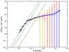 |
Fig. 7 Error on the 3d 21 cm power spectrum at z = 20.25
( |

With the above measurements of the 3d power spectra, we should be able to constrain some of the characteristics of the first galaxies such as their emission spectra. Although, as we have seen, the Lyα signal dominates on larger scales over other contributions, these constraints will be particularly strong if we fix the cosmology, which should be a reasonable assumption given the expected level of constraints from the Planck satellite.
Up to now we have been assuming a type II emission spectrum with a total of 20 000 photons per baryon emitted between the Lyα and Lyman limit frequency. If instead we assume that the stars responsible for the Lyα coupling are Pop III, we should have around 5000 photons emitted per baryon used in stars with a spectral index of α = 0.29. Figure 8 shows the results of changing the emission model with the dashed curves corresponding to the PopIII case (note that due to the lower number of photons, these lines also correspond to a lower ⟨ xα ⟩ of 0.1. The dotted curve corresponds to changing the spectral index to α = 0.29 while maintaining the total emission to 5000 photons, which will be difficult to distinguish under the current noise expectations (the total number of emitted photons per baryon is the most relevant parameter for the Lyα flux). Another possibility is to assume that Pop III stars are also being formed in halos with mass less than 108 M⊙. The green dot-dashed line in Fig. 8 shows the effect of considering halos down to 106 M⊙ from simulation S1 at the same redshift. Note that this has a much higher coupling and if we consider higher redshifts so that ⟨ xα ⟩ ~ 0.1 the line will be closer to the dashed one.
 |
Fig. 8 21 cm temperature power spectrum for a few Lyman alpha emission models and simulations S1 and S2. Top black solid lines correspond to ⟨ xα ⟩ = 0.4 while bottom dashed/dotted curves to ⟨ xα ⟩ = 0.1 (all at z ~ 20.25). The green dot-dashed line uses halos down to 106 M⊙ and a Pop III type emission spectra. The error bars in blue corresponds to the full SKA while the ones in red to 10% of the collecting area. |
These calculations show that it should be possible for SKA to measure ⟨ xα ⟩ from observations of the 21 cm power spectrum at z ≈ 20. Given a detailed model and small error bars this could be measured directly from the shape of the power spectrum. More generally, if measured over only a small range of wave-numbers, the redshift dependence of ⟨ xα ⟩ could be extracted by looking at the redshift evolution of the amplitude and slope in a manner analogous to that suggested by Lidz et al. (2008) for reionization. Note that, although during Lyα domination different models have similar power spectra for the same ⟨ xα ⟩ , its evolution with redshift could be used to distinguish these models.
Measurements of ⟨ xα ⟩ in a number of different redshift bins would be instrumental in constructing a “21 cm Madau plot” (Madau et al. 1996). The Madau plot shows the evolution of the star formation rate as a function of redshift and producing such a plot in the very early Universe would be a major accomplishment of SKA. Measurements of ⟨ xα ⟩ do not give this directly, since in our model ⟨ xα ⟩ is determined by the product of the star-formation rate and the emissivity of the galaxies. Breaking this degeneracy observationally will be difficult and would lead to a plot whose absolute normalisation was uncertain, but whose shape tracked the star-formation rate (assuming no evolution of the galaxies). However, for many models of early galaxy formation (Leitherer et al. 1999; Bromm & Larson 2004) the variation in the number of Lyα photons produced per baryon is only a factor of two or so. Thus with a reasonable theoretical prior a useful measure of the star-formation history could be established.
4. Redshift space distortions
The signal we are trying to probe is actually anisotropic due to the redshift space
distortions set by the peculiar velocity of the HI gas, which is already being taken into
account in Eq. (5). Using a linear
approximation,  and
and
 so to first order the fluctuation in Tb becomes
 (14)The peculiar velocity field
originates from inhomogeneities in the density field, so that in Fourier space we can use
Kaiser’s approximation
(14)The peculiar velocity field
originates from inhomogeneities in the density field, so that in Fourier space we can use
Kaiser’s approximation  (Kaiser 1987) to write the velocity as a function of its
dependence in μ = cos(θ). This linear approximation in the
velocity contribution allows the brightness temperature power spectra to be separated in
only three powers of μ:
(Kaiser 1987) to write the velocity as a function of its
dependence in μ = cos(θ). This linear approximation in the
velocity contribution allows the brightness temperature power spectra to be separated in
only three powers of μ:  (15)with
  (16)
(16)![Mathematical equation: \begin{equation} P_{\mu^2}(k)=2 C^2(z)\left[(1+\beta)P_{\delta}(k)+\frac{1}{1+\langle x_{\alpha}\rangle}P_{\delta\delta_{x_{\alpha}}}(k)\right], \label{Pmu2} \end{equation}](/articles/aa/full_html/2011/03/aa15695-10/aa15695-10-eq200.png) (17)and
(17)and ![Mathematical equation: \begin{eqnarray} P_{\mu^0}(k)&=&C^2(z)\Bigg[(1+\beta)^2P_{\delta}(k)\nonumber\\ &&+\left.\left(\frac{1}{1+\langle x_{\alpha}\rangle}\right)^2P_{\delta_{x_{\alpha}}\delta_{x_{\alpha}}}(k)+\frac{2(1+\beta)}{1+\langle x_{\alpha}\rangle}P_{\delta\delta_{x_{\alpha}}}(k)\right], \label{Pmu0} \end{eqnarray}](/articles/aa/full_html/2011/03/aa15695-10/aa15695-10-eq201.png) (18)where
the power spectra Pab(k) for
generic quantities a and b is defined as:
(18)where
the power spectra Pab(k) for
generic quantities a and b is defined as:
 (19)This decomposition
can be particularly useful at the high redshifts we are considering, where, as can be seen
from Fig. 6, the contribution from the velocity
compression can be relatively strong. By fitting the observed signal to the above polynomial
(Eq. (15)) at each k, we
can in principle separate the cosmological and astrophysical contributions to the brightness
temperature fluctuations (Barkana & Loeb
2005a,b). One can use
Pμ2 and
Pμ0 to learn about the first
sources of radiation while the Pμ4
term could be used to measure the matter power spectrum directly, with no interference from
any other sources of fluctuations.
(19)This decomposition
can be particularly useful at the high redshifts we are considering, where, as can be seen
from Fig. 6, the contribution from the velocity
compression can be relatively strong. By fitting the observed signal to the above polynomial
(Eq. (15)) at each k, we
can in principle separate the cosmological and astrophysical contributions to the brightness
temperature fluctuations (Barkana & Loeb
2005a,b). One can use
Pμ2 and
Pμ0 to learn about the first
sources of radiation while the Pμ4
term could be used to measure the matter power spectrum directly, with no interference from
any other sources of fluctuations.
4.1. Assumptions on linearity
 |
Fig. 9 Power spectra of brightness temperature fluctuations using simulation S1 (dotted lines) and using simulation S2 (solid lines) for ⟨ xα ⟩ = 0.4 (z ~ 20.25). Blue lines (top) use the exact velocity contribution and red lines (bottom) use a first order approximation in the velocity contribution. |
The decomposition discussed in the previous section relies on assumptions of linearity in both the velocity field and the Lyα fluctuations. On small scales, both of these assumptions may break down and we consider both in turn. As we go to small scales, fluctuations on the density field increase and the non-linearities in the velocity contribution can become important, so that the first order approximation to the full velocity term in Eq. (1) breaks down. Figure 9 compares the brightness temperature power spectrum from the full calculation with the case where we assume the first order approximation for the velocity. We see that for k ≳ 1.0 h/Mpc the non-linearities can become important. This result implies that for smaller scales the correct brightness temperature power spectra has a much more complicated dependence in μ than the one given by Eq. (15) which will complicate the model independent extraction of the astrophysical contributions (Shaw & Lewis 2008).
Fluctuations in the Lyα background too can leave the linear regime. The information from the Lyα background and consequently from the physical processes that originated it, is contained in δxα and it can only be directly obtained from the power spectrum angular separation in powers of μ for scales where the linear approximation of Aα is valid. To show the limits where the first order approximation can be used, we plotted in Fig. 10 the power spectra of Aα compared to its linear expression, using the values from simulation S1. The linear approximation should be valid for k ≲ 0.2 h/Mpc.
 |
Fig. 10 Power spectra of fluctuations in xα/(1 + xα) built using simulation S1 for ⟨ xα ⟩ = 0.4 (z ~ 20.25). The figure shows the the total fluctuation (solid green line) and its first order approximation (dashed red line). |
 |
Fig. 11 Detail of the histogram of fluctuations in δxα using simulation S1 for ⟨ xα ⟩ = 0.4 (z ~ 20.25). The fluctuations in δxα go from -50 till 350. |
Looking at the histogram of δxα in Fig. 11 we see that there are few points where δxα > 1. Although this number is small compared to the overall distribution (most cells in the simulation have actually xα ~ 0 at these high redshifts), they are enough to introduce non-linearities on the power spectrum calculation. This basically implies that for small scales the fluctuations in xα will have a large dependence on the random distribution of the first galaxies so it will only be possible to do a linear approximation on Aα for scales large enough that a few small peaks of large intensity do not dominate the power spectra of the fluctuation. Some of the strong coupling regions coincide with ionized regions which may diminish the effect of strong fluctuations in the brightness temperature power spectra, however according with simulations S1, S2 and S3, at the high redshifts we are interested (z > 20) the ionized regions are so small that including this quantity has no meaningful effect in the linear approximation used.
From this study we can conclude that the brightness temperature power spectrum angular separation in Eq. (15) should be reasonable for k < 1 h/Mpc and the linear approximations in Eqs. (17) and (18) should be valid for larger scales, k ≲ 0.2 h/Mpc, allowing the direct extraction of information about the Lyα field (Barkana & Loeb 2005b). This is fortunate since it corresponds to the scales where the Lyα fluctuations dominate the contributions to the brightness temperature (Fig. 6) as well as the scales where the SKA should perform better (Fig. 7). For 0.2 ≲ k ≲ 1.0 h/Mpc we can still use the angular decomposition but Eqs. (17) and (18) will include higher order terms. Given the scales we are interested in, from now on we will concentrate on simulation S1 (1000 Mpc) which can be used to calculate the power spectrum up to k ~ 2.3 h/Mpc.
4.2. Constraints on P (k,μ)
 |
Fig. 12 Expected measurements for the SKA of the 21 cm power spectrum as a function of the
angle with the line of sight (z = 20.25,
|

 |
Fig. 13 Contributions for the 21 cm temperature power spectrum using simulations (solid lines), built using simulation S1 for ⟨ xα ⟩ = 0.4 (z ~ 20.25). Dashed lines: expected errors. Dotted lines: expected errors assuming that Pμ4 is known. Solid lines from top to bottom are Pμ0 (green), Pμ2 (red) and Pμ4 (blue). |
As we have seen in the previous section, the redshift space distortions introduce an anisotropy in the 21 cm power spectrum that, in the linear regime, depends on k and even powers of μ. More generally non-linearities in the velocity field will introduce terms with more complicated dependence (Shaw & Lewis 2008). Measurements of P(k,μ) might provide more information on the Lyα signal (Barkana & Loeb 2005a) than the spherical average P(k) we considered so far. Figure 12 shows the expected errors in the measurements of the 3d power spectrum as a function of μ, for an SKA type experiment (Table 2). The calculation follows Eq. (7) where the number of modes in each bin is now a function of k and μ. We used bins with a logarithmic spacing in k and linear in μ (with 0 ≤ μ ≤ 1 since the power spectrum only depends on μ2). The number of modes in each bin is accounted for by gridding the k space with a resolution along the line of sight set by the interval in frequency used for the analysis and a resolution perpendicular to the line of sight set by the field of view (see Sect. 3.2). The minimum size of the bins is given by this resolution. Note that the number of independent μ bins increase with k, although, as can be seen from Fig. 12, the errors will also increase due to the experimental noise. Moreover, the power spectrum is quite flat for small k which will make it harder to extract the polynomial dependence (this is because the Pμ0 term is dominating in Eq. (15)).
Although difficult as we have seen, we can try to obtain
Pμ0,
Pμ2 and
Pμ4 by fitting Eq. (15) to the measured
P(k,μ) for k ≲ 1.0 h/Mpc. This in
turn should allow us to obtain direct constraints on a combination of
Pδxαδxα
and
Pδδxα.
For small k there are fewer bins so the uncertainty in
Pμn will be
high even for those scales where the errors in P(k,μ)
are small. The expected errors on the
Pμn term
can be obtained using a Fisher matrix approach (Fisher
1935). For parameters
a,b = { Pμ0,Pμ2,Pμ4 } ,
the matrix is calculated through  (20)where
again P(k,μ) is given by Eq. (15) and
ΔP(ki,μj)
is the error for each bin. The covariance of the
Pμn terms
is just the inverse of the Fisher matrix and Fig. 13
shows the expected 1-sigma errors (
(20)where
again P(k,μ) is given by Eq. (15) and
ΔP(ki,μj)
is the error for each bin. The covariance of the
Pμn terms
is just the inverse of the Fisher matrix and Fig. 13
shows the expected 1-sigma errors ( ).
We see that it should be possible to measure with reasonable accuracy both the
Pμ0 and
Pμ2 terms which can already
give us interesting constraints on the Lyα field. In fact, if we fix the
cosmology (e.g. Pδ), then we should be able
to extract information from
Pδδxα
and
Pδxαδxα
separately. On the other hand, the
Pμ4 will be hard to measure,
which will make the extraction of cosmological information more difficult, simply because
it is an order of magnitude smaller than the other terms on the scales we are focusing
here.
).
We see that it should be possible to measure with reasonable accuracy both the
Pμ0 and
Pμ2 terms which can already
give us interesting constraints on the Lyα field. In fact, if we fix the
cosmology (e.g. Pδ), then we should be able
to extract information from
Pδδxα
and
Pδxαδxα
separately. On the other hand, the
Pμ4 will be hard to measure,
which will make the extraction of cosmological information more difficult, simply because
it is an order of magnitude smaller than the other terms on the scales we are focusing
here.
In order to improve this last constraint we would have to increase the collecting area of the instrument and the frequency interval used (4 MHz in this case) so to have more modes along the line of sight (note however that this will lead to cosmological evolution of the signal along the frequency bin, as already discussed). The SKA should be able to measure modes up to k ~ 10 h/Mpc which could have higher values of Pμ4, however for k > 1 h/Mpc the angular decomposition is no longer valid and the separate measurements of the P(k,μ) terms will be of little use (except maybe for foreground removal).
In this case, it might be better to just try to fit the parameters of the model directly to the averaged power spectrum P(k) using the simulations (as shown in Fig. 8). If on the other hand we assume we already know Pμ4 with reasonable accuracy then the errors on Pμ2 will improve considerably (Fig. 13) and any degeneracies between Pμ0 and Pμ2 will be broken.
4.3. Extracting the Poisson term
Finally, by measuring the P(k,μ) terms, we can in
principle use an estimator to probe the properties of the first sources of radiation
directly through the Lyα field, without having to go through a full,
model dependent, parameter fit to the data. This is based on the decomposition proposed in
Barkana & Loeb (2005a), valid in the
linear regime. In that case,
δxα can be
expressed as a function of its dependence on effects correlated and uncorrelated with
δ as:  (21)Note that this
decomposition is actually quite general and the main assumption here is the linearity on
δ. δP is the Poisson contribution that
arises from the statistical fluctuations in the number density of the rare first galaxies
(galaxies being discrete objects and therefore not tracking the continuous density field
perfectly) and which to first order is uncorrelated with the density fluctuations.
(21)Note that this
decomposition is actually quite general and the main assumption here is the linearity on
δ. δP is the Poisson contribution that
arises from the statistical fluctuations in the number density of the rare first galaxies
(galaxies being discrete objects and therefore not tracking the continuous density field
perfectly) and which to first order is uncorrelated with the density fluctuations.
The window function, W(k), contains several effects by
which δxα is
related to the underlying matter density fluctuations, δ (see Barkana & Loeb 2005b for details). The strongest
effect between δ and
δxα is the
biasing of the number density of galaxies with respect to the density fluctuations by a
factor b(z) (the average halo bias) so that an overdense
region will have a factor (1 + b(z)δ)
more sources (Mo & White 1996). This is the
only term that is implicitly included in our simulations through the way we do the 3d
integration of the Lyα flux. Note however that this term completely
dominates over the other terms in Barkana & Loeb
(2005b) since b(z) ~ 15 at
z ~ 20. In that case, we can express
W(k) as:  (22)where
D(z) is the linear growth function and we are just
considering photons emitted below the Lyman beta limit for comparison, so that
zmax(2) = (32/27)(1 + z) − 1 (Barkana & Loeb 2005b; Pritchard & Furlanetto 2007).
(22)where
D(z) is the linear growth function and we are just
considering photons emitted below the Lyman beta limit for comparison, so that
zmax(2) = (32/27)(1 + z) − 1 (Barkana & Loeb 2005b; Pritchard & Furlanetto 2007).
 |
Fig. 14 Window function for simulation S1 considering only photons emitted below the Lyman beta limit, for ⟨ xα ⟩ = 0.4 (z ~ 20.25). Solid lines are obtained using Eq. (22) and dotted lines are obtained using Pδδxα(k) and Pδ(k). |
Using the parametrization of δxα we can write Pxα(k) = W2(k)Pδ(k) + Pp(k) and Pδδxα(k) = W(k)Pδ(k), meaning that we can isolate W(k) from the simulations (W(k) = Pδδxα(k)/Pδ(k)). In Fig. 14 we show the window function obtained from Eq. (22), with values from simulation S1, which has the same behavior as the one computed by Pritchard & Furlanetto (2007). Figure 14 also shows that the window function obtained from Eq. (22) has a higher amplitude for large scales and small scales than the one obtained from simulation S1 using Pδ and Pδδxα. On large scales this is probably a consequence of our box still not being quite large enough to encompass the rarest, most highly biased objects leading to an underestimate of the power on large scales. On small scales, this seems to be a consequence of the onset of non-linearities in the density and Lyα fields. On scales close enough to clusters of sources that the Lyα coupling saturates, we might expect to see a steeper fall off in the 21 cm power as seen here. Nevertheless, W(k) obtained from the simulation follows quite closely the expected theoretical values, which supports the decomposition given in Eq. (21) and validates the signal extraction we discuss next.
 |
Fig. 15 Power spectra of fluctuations in xα using simulation S1 for ⟨ xα ⟩ = 0.4 (z ~ 20.25). Shown are Pxα (solid line), W2Pδ (dashed line) and Pp(dotted line). |
 |
Fig. 16 Power spectra of brightness temperature fluctuations using simulation S1 for ⟨ xα ⟩ = 0.4 (z ~ 20.25). Shown are Pμ2 (green dashed line) 2C(z)Pδ (blue solid line), and Pun − δ (red dotted line). |
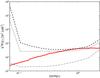 |
Fig. 17 Power spectra of C2(z)(1/(1 + ⟨ xα ⟩ ))2Pp(k) (solid line), built using simulation S1 for ⟨ xα ⟩ = 0.4 (z ~ 20.25). Expected error (dashed line) and expected error assuming that Pδ is known (dotted line), so the error in Pμ4 comes only from C(z). Dot-dashed line assumes that C(z) is known to high accuracy. |
![Mathematical equation: \begin{equation} \frac{P_{\mu^2}(k)}{P_{\mu^4}(k)}=2\times\left[1+\beta+\frac{1}{1+\langle x_{\alpha}\rangle}W(k)\right], \label{W_obs} \end{equation}](/articles/aa/full_html/2011/03/aa15695-10/aa15695-10-eq266.png) (23)and the Poisson
contribution uncorrelated with δ:
(23)and the Poisson
contribution uncorrelated with δ:  (24)The use of Eqs. (23) and (24) allows us to characterize the Lyα background and
the number and distribution of galaxies at these early redshifts. In Fig. 16, we used simulation S1 to show
Pun − δ and
Pμ2, which are consistent with
the results obtained by Barkana & Loeb
(2005b). Figure 17 shows the power spectra
of the Poisson contribution (Eq. (24)) and
the expected errors associated with this measurement. As expected, due to the high error
in Pμ4, the measurement of this
Poisson term will be quite difficult even with the assumed experimental setup (dashed
line). If we assume that the matter power spectrum is known with reasonable accuracy from
CMB data and galaxy surveys, then we can combine the measurement of the
Pμ4 term at several
k to constrain C2(z)
(Eq. (16)), e.g. the mean brightness
temperature on the sky. Unfortunately the constraint is still large,
C2(z) ≈ (6.42 ± 5.60) × 103mK2,
which translates into large errors for the Poisson term (dotted lines). Nevertheless, a
detection will still be possible, with a signal to noise of 2.6 (dashed line) and 3.8
(dotted line).
(24)The use of Eqs. (23) and (24) allows us to characterize the Lyα background and
the number and distribution of galaxies at these early redshifts. In Fig. 16, we used simulation S1 to show
Pun − δ and
Pμ2, which are consistent with
the results obtained by Barkana & Loeb
(2005b). Figure 17 shows the power spectra
of the Poisson contribution (Eq. (24)) and
the expected errors associated with this measurement. As expected, due to the high error
in Pμ4, the measurement of this
Poisson term will be quite difficult even with the assumed experimental setup (dashed
line). If we assume that the matter power spectrum is known with reasonable accuracy from
CMB data and galaxy surveys, then we can combine the measurement of the
Pμ4 term at several
k to constrain C2(z)
(Eq. (16)), e.g. the mean brightness
temperature on the sky. Unfortunately the constraint is still large,
C2(z) ≈ (6.42 ± 5.60) × 103mK2,
which translates into large errors for the Poisson term (dotted lines). Nevertheless, a
detection will still be possible, with a signal to noise of 2.6 (dashed line) and 3.8
(dotted line).
If we further assume that we combine this result with the measurements from a global experiment in order to measure the mean brightness temperature with high accuracy, then we can extract all the relevant power spectra reasonably well (dot-dashed line).
5. Conclusions
In this paper, we have made use of a recently developed fast semi-numerical code to explore the possibility for 21 cm observations of the time of the first galaxies with SKA. We demonstrated that this code allows the simulation of the full range of scales likely to be accessible to observations. Here we have focused on the impact of 21 cm fluctuations from large fluctuations in the Lyα coupling, which arise due to the clustering of the rare first galaxies and considered different emission models.
Measurement of these fluctuations would provide insight into the formation of the very first galaxies and would be highly complementary with the next generation of large optical/IR telescopes. We have shown that SKA-pathfinders with ~10% of the full collecting area should be capable of making a statistical detection of the 21 cm power spectrum at redshifts z ≲ 20. With the full SKA sensitivity this detection would become a measurement allowing astrophysical properties of the first galaxies to be determined. Note that it is crucial that these experiments are able to go below 70 MHz in order to probe the signal.
Observations with an SKA-like instrument would enable the determination of ⟨ xα ⟩ as a function of redshift from the amplitude and shape of the 21 cm fluctuations. Although different models with the same ⟨ xα ⟩ give similar power spectra, this evolution with redshift should allow to distinguish them. Even though there is a strong degeneracy between the star formation rate and the UV spectral properties of the galaxies themselves, these observations would enable constraints to be placed on the star formation rate in the earliest generations of galaxies. Although crude, the resulting “Madau plot” would be very useful for understanding the formation processes of the first galaxies.
Moving beyond the angle-averaged power spectrum, we have investigated the use of redshift-space distortions to separate out different components of the power spectrum as suggested by Barkana & Loeb (2005b). These measurements are difficult due to instrumental limitations and are further complicated by non-linearities on small scales. For the first time, we have investigated the non-linearity of Lyα fluctuations showing that they should be important on scales k ≳ 0.2 (h/Mpc). Nonetheless, on larger scales the detection of these effects is possible with SKA level sensitivity and should allow to put direct constraints on the Lyα power spectrum.
Redshift space distortions further offer the possibility of extracting components of the power spectrum that do not correlate with the density field. This Poissonian component contains direct information about the number density of sources and so gives complementary information to the other sources of fluctuations. We have shown that a detection is possible and if strong assumptions about the underlying cosmology are possible and combined with information about the mean 21 cm signal, then these fluctuations may be picked out clearly by SKA.
These results illustrate the potential of 21 cm observations to shed new light on the astrophysics during the pre-Reionization epoch. In the future, our improved knowledge of cosmological parameters will provide a firm foundation to pick out the details of galaxy formation in the early Universe. SKA and pathfinders capable of observing at frequencies ν ≲ 100 MHz will begin to access this interesting period and transform our understanding of the cosmic dawn.
Available at http://simfast21.org.
Acknowledgments
This work was partially supported by FCT-Portugal under grants PTDC/FIS/66825/2006 and PTDC/FIS/100170/2008. J.R.P. is supported by NASA through Hubble Fellowship grant HST-HF-01211.01-A awarded by the Space Telescope Science Institute, which is operated by the Association of Universities for Research in Astronomy, Inc., for NASA, under contract NAS 5-26555. A.C. acknowledges support of NSF grant CAREER AST-0645427. M.G.S. was a visitor at UCI when this work was concluded.
References
- Baek, S., Di Matteo, P., Semelin, B., Combes, F., & Revaz, Y. 2009, A&A, 495, 389 [NASA ADS] [CrossRef] [EDP Sciences] [Google Scholar]
- Baek, S., Semelin, B., Di Matteo, P., Revaz, Y., & Combes, F. 2010, 523, A4 [Google Scholar]
- Barkana, R., & Loeb, A. 2001, Phys. Rep., 349, 125 [NASA ADS] [CrossRef] [Google Scholar]
- Barkana, R., & Loeb, A. 2004, ApJ, 609, 474 [NASA ADS] [CrossRef] [Google Scholar]
- Barkana, R., & Loeb, A. 2005a, ApJ, 624, L65 [NASA ADS] [CrossRef] [Google Scholar]
- Barkana, R., & Loeb, A. 2005b, ApJ, 626, 1 [NASA ADS] [CrossRef] [Google Scholar]
- Bowman, J. D., Morales, M. F., & Hewitt, J. N. 2006, ApJ, 638, 20 [NASA ADS] [CrossRef] [Google Scholar]
- Bowman, J. D., Morales, M. F., & Hewitt, J. N. 2007, ApJ, 661, 1 [NASA ADS] [CrossRef] [Google Scholar]
- Bromm, V., & Larson, R. B. 2004, ARA&A, 42, 79 [NASA ADS] [CrossRef] [EDP Sciences] [Google Scholar]
- Chuzhoy, L., & Zheng, Z. 2007, ApJ, 670, 912 [NASA ADS] [CrossRef] [Google Scholar]
- Cohen, A. S., & Röttgering, H. J. A. 2009, AJ, 138, 439 [NASA ADS] [CrossRef] [Google Scholar]
- Cohn, J. D., & White, M. 2008, MNRAS, 385, 2025 [NASA ADS] [CrossRef] [Google Scholar]
- Cuby, J., Hibon, P., Lidman, C., et al. 2007, A&A, 461, 911 [NASA ADS] [CrossRef] [EDP Sciences] [Google Scholar]
- Faulkner, A. J. E. A. 2010, SKADS Memos: http://www.skads-eu.org [Google Scholar]
- Field, G. B. 1959, ApJ, 129, 536 [NASA ADS] [CrossRef] [Google Scholar]
- Fisher, R. 1935, J. Roy. Stat. Soc., 98, 39 [CrossRef] [Google Scholar]
- Furlanetto, S. R., Oh, S. P., & Briggs, F. H. 2006, Phys. Rep., 433, 181 [NASA ADS] [CrossRef] [Google Scholar]
- Garrett, M. A., Cordes, J. M., Deboer, D. R., et al. 2010 [arXiv:1008.2871] [Google Scholar]
- Harker, G., Zaroubi, S., Bernardi, G., et al. 2010, MNRAS, 405, 2492 [NASA ADS] [Google Scholar]
- Heitmann, K., Lukic, Z., Fasel, P., et al. 2008, Comp. Science and discov., 1, 015003 [Google Scholar]
- Hibon, P., Cuby, J., Willis, J., et al. 2010, A&A, 515, A97 [NASA ADS] [CrossRef] [EDP Sciences] [Google Scholar]
- Hirata, C. M. 2006, MNRAS, 367, 259 [NASA ADS] [CrossRef] [Google Scholar]
- Jelić, V., Zaroubi, S., Labropoulos, P., et al. 2008, MNRAS, 389, 1319 [NASA ADS] [CrossRef] [Google Scholar]
- Kaiser, N. 1987, MNRAS, 227, 1 [NASA ADS] [CrossRef] [Google Scholar]
- Komatsu, E., Smith, K. M., Dunkley, J., et al. 2011, ApJS, 192, 18 [NASA ADS] [CrossRef] [Google Scholar]
- Leitherer, C., Schaerer, D., Goldader, J. D., et al. 1999, ApJS, 123, 3 [NASA ADS] [CrossRef] [Google Scholar]
- Lewis, A., Challinor, A., & Lasenby, A. 2000, ApJ, 538, 473 [NASA ADS] [CrossRef] [Google Scholar]
- Lidz, A., Zahn, O., McQuinn, M., Zaldarriaga, M., & Hernquist, L. 2008, ApJ, 680, 962 [NASA ADS] [CrossRef] [Google Scholar]
- Liu, A., Tegmark, M., Morrison, S., Lutomirski, A., & Zaldarriaga, M. 2010, MNRAS, 408, 1029 [NASA ADS] [CrossRef] [Google Scholar]
- Lukic, Z., Heitmann, K., Habib, S., Bashinsky, S., & Ricker, P. M. 2007, ApJ, 671, 1160 [NASA ADS] [CrossRef] [Google Scholar]
- Madau, P., Ferguson, H. C., Dickinson, M. E., et al. 1996, MNRAS, 283, 1388 [NASA ADS] [CrossRef] [Google Scholar]
- Mao, Y., Tegmark, M., McQuinn, M., Zaldarriaga, M., & Zahn, O. 2008, Phys. Rev. D, 78, 023529 [NASA ADS] [CrossRef] [Google Scholar]
- Matejek, M. S., & Morales, M. F. 2009, ArXiv e-prints [Google Scholar]
- McMahon, R., Parry, I., Venemans, B., et al. 2008, The Messenger, 131, 11 [NASA ADS] [Google Scholar]
- McQuinn, M., Zahn, O., Zaldarriaga, M., Hernquist, L., & Furlanetto, S. R. 2006, ApJ, 653, 815 [NASA ADS] [CrossRef] [Google Scholar]
- Mesinger, A., Furlanetto, S., & Cen, R. 2010 [arXiv:1003.3878] [Google Scholar]
- Mo, H. J., & White, S. D. M. 1996, MNRAS, 282, 347 [NASA ADS] [CrossRef] [Google Scholar]
- Morales, M. F., Bowman, J. D., & Hewitt, J. N. 2006, ApJ, 648, 767 [NASA ADS] [CrossRef] [Google Scholar]
- Nilsson, K. K., Orsi, A., Lacey, C. G., Baugh, C. M., & Thommes, E. 2007, A&A, 474, 385 [NASA ADS] [CrossRef] [EDP Sciences] [Google Scholar]
- Ouchi, M., Shimasaku, K., Akiyama, M., et al. 2008, ApJS, 176, 301 [NASA ADS] [CrossRef] [Google Scholar]
- Pritchard, J. R., & Furlanetto, S. R. 2006, MNRAS, 367, 1057 [NASA ADS] [CrossRef] [Google Scholar]
- Pritchard, J. R., & Furlanetto, S. R. 2007, MNRAS, 376, 1680 [NASA ADS] [CrossRef] [Google Scholar]
- Pritchard, J. R., & Loeb, A. 2008, Phys. Rev. D, 78, 103511 [NASA ADS] [CrossRef] [Google Scholar]
- Pritchard, J. R., & Loeb, A. 2010, Phys. Rev. D, 82, 023006 [NASA ADS] [CrossRef] [Google Scholar]
- Reed, D. S., Bower, R., Frenk, C. S., Jenkins, A., & Theuns, T. 2007, MNRAS, 374, 2 [NASA ADS] [CrossRef] [Google Scholar]
- Salvaterra, R., Ferrara, A., & Dayal, P. 2010 [arXiv:1003.3873] [Google Scholar]
- Santos, M. G., Cooray, A., & Knox, L. 2005, ApJ, 625, 575 [NASA ADS] [CrossRef] [Google Scholar]
- Santos, M. G., Amblard, A., Pritchard, J., et al. 2008, ApJ, 689, 1 [NASA ADS] [CrossRef] [Google Scholar]
- Santos, M. G., Ferramacho, L., Silva, M. B., Amblard, A., & Cooray, A. 2010, MNRAS, 406, 2421 [NASA ADS] [CrossRef] [Google Scholar]
- Schaerer, D. 2003a, A&A, 397, 527 [NASA ADS] [CrossRef] [EDP Sciences] [Google Scholar]
- Schaerer, D. 2003b, A&A, 397, 527 [NASA ADS] [CrossRef] [EDP Sciences] [Google Scholar]
- Schilizzi, R. T., Alexander, P., Cordes, J. M., et al. 2007, SKA documents: http://www.skatelescope.org [Google Scholar]
- Semelin, B., Combes, F., & Baek, S. 2007, A&A, 474, 365 [NASA ADS] [CrossRef] [EDP Sciences] [Google Scholar]
- Shaw, J. R., & Lewis, A. 2008, Phys. Rev. D, 78, 103512 [NASA ADS] [CrossRef] [Google Scholar]
- Stark, D. P., Ellis, R. S., Richard, J., et al. 2007, ApJ, 663, 10 [NASA ADS] [CrossRef] [Google Scholar]
- Stiavelli, M., Fall, S. M., & Panagia, N. 2004, ApJ, 610, L1 [NASA ADS] [CrossRef] [Google Scholar]
- Trac, H., & Cen, R. 2007, ApJ, 671, 1 [NASA ADS] [CrossRef] [Google Scholar]
- Trac, H., & Pen, U.-L. 2004, New Astron., 9, 443 [NASA ADS] [CrossRef] [Google Scholar]
- Trac, H., & Pen, U.-L. 2006, New Astron., 11, 273 [NASA ADS] [CrossRef] [Google Scholar]
- Trac, H., Cen, R., & Loeb, A. 2008, ApJ, 689, L81 [NASA ADS] [CrossRef] [Google Scholar]
- Willis, J. P., Courbin, F., Kneib, J., & Minniti, D. 2008, MNRAS, 384, 1039 [NASA ADS] [CrossRef] [Google Scholar]
- Wouthuysen, S. A. 1952, AJ, 57, 31 [NASA ADS] [CrossRef] [Google Scholar]
- Zahn, O., Lidz, A., McQuinn, M., et al. 2007, ApJ, 654, 12 [NASA ADS] [CrossRef] [Google Scholar]
All Tables
All Figures
|
Fig. 1 The 21 cm brightness temperature with all fluctuations included. Dotted – simulation S1, solid – simulation S2, dashed – simulation S3. Redshifts from top to bottom are: 19.25 (⟨ xα ⟩ = 0.9), 20.25 (⟨ xα ⟩ = 0.4), 22.5 (⟨ xα ⟩ = 0.06). The black dash-dotted line shows the correction for ⟨ xα ⟩ = 0.4 when doing the full Lyα flux inhomogeneous integration. |
| In the text | |
|
Fig. 2 Power spectrum of
|
| In the text | |
|
Fig. 3 The average xα and xc coupling parameters as a function of redshift for the S2 simulation. The Lyα coupling dominates over collisions at all redshifts considered. |
| In the text | |
|
Fig. 4 The fluctuations from Lyα ,
Aα (solid) and the gas temperature,
|
| In the text | |
|
Fig. 5
|
| In the text | |
|
Fig. 6 The 21 cm power spectrum and its main contributions at ⟨ xα ⟩ = 0.4 (z ~ 20.25) using simulation S1 (red) and simulation S2 (blue). Top solid lines – all contributions included; dashed – Lyα only; dotted – matter density; bottom thin solid lines – fluctuations on the gas temperature from adiabatic cooling only; dot-dashed – velocity fluctuations only. |
| In the text | |
|
Fig. 7 Error on the 3d 21 cm power spectrum at z = 20.25
( |
| In the text | |
|
Fig. 8 21 cm temperature power spectrum for a few Lyman alpha emission models and simulations S1 and S2. Top black solid lines correspond to ⟨ xα ⟩ = 0.4 while bottom dashed/dotted curves to ⟨ xα ⟩ = 0.1 (all at z ~ 20.25). The green dot-dashed line uses halos down to 106 M⊙ and a Pop III type emission spectra. The error bars in blue corresponds to the full SKA while the ones in red to 10% of the collecting area. |
| In the text | |
|
Fig. 9 Power spectra of brightness temperature fluctuations using simulation S1 (dotted lines) and using simulation S2 (solid lines) for ⟨ xα ⟩ = 0.4 (z ~ 20.25). Blue lines (top) use the exact velocity contribution and red lines (bottom) use a first order approximation in the velocity contribution. |
| In the text | |
|
Fig. 10 Power spectra of fluctuations in xα/(1 + xα) built using simulation S1 for ⟨ xα ⟩ = 0.4 (z ~ 20.25). The figure shows the the total fluctuation (solid green line) and its first order approximation (dashed red line). |
| In the text | |
|
Fig. 11 Detail of the histogram of fluctuations in δxα using simulation S1 for ⟨ xα ⟩ = 0.4 (z ~ 20.25). The fluctuations in δxα go from -50 till 350. |
| In the text | |
|
Fig. 12 Expected measurements for the SKA of the 21 cm power spectrum as a function of the
angle with the line of sight (z = 20.25,
|
| In the text | |
|
Fig. 13 Contributions for the 21 cm temperature power spectrum using simulations (solid lines), built using simulation S1 for ⟨ xα ⟩ = 0.4 (z ~ 20.25). Dashed lines: expected errors. Dotted lines: expected errors assuming that Pμ4 is known. Solid lines from top to bottom are Pμ0 (green), Pμ2 (red) and Pμ4 (blue). |
| In the text | |
|
Fig. 14 Window function for simulation S1 considering only photons emitted below the Lyman beta limit, for ⟨ xα ⟩ = 0.4 (z ~ 20.25). Solid lines are obtained using Eq. (22) and dotted lines are obtained using Pδδxα(k) and Pδ(k). |
| In the text | |
|
Fig. 15 Power spectra of fluctuations in xα using simulation S1 for ⟨ xα ⟩ = 0.4 (z ~ 20.25). Shown are Pxα (solid line), W2Pδ (dashed line) and Pp(dotted line). |
| In the text | |
|
Fig. 16 Power spectra of brightness temperature fluctuations using simulation S1 for ⟨ xα ⟩ = 0.4 (z ~ 20.25). Shown are Pμ2 (green dashed line) 2C(z)Pδ (blue solid line), and Pun − δ (red dotted line). |
| In the text | |
|
Fig. 17 Power spectra of C2(z)(1/(1 + ⟨ xα ⟩ ))2Pp(k) (solid line), built using simulation S1 for ⟨ xα ⟩ = 0.4 (z ~ 20.25). Expected error (dashed line) and expected error assuming that Pδ is known (dotted line), so the error in Pμ4 comes only from C(z). Dot-dashed line assumes that C(z) is known to high accuracy. |
| In the text | |
Current usage metrics show cumulative count of Article Views (full-text article views including HTML views, PDF and ePub downloads, according to the available data) and Abstracts Views on Vision4Press platform.
Data correspond to usage on the plateform after 2015. The current usage metrics is available 48-96 hours after online publication and is updated daily on week days.
Initial download of the metrics may take a while.