| Issue |
A&A
Volume 511, February 2010
|
|
|---|---|---|
| Article Number | A57 | |
| Number of page(s) | 25 | |
| Section | Extragalactic astronomy | |
| DOI | https://doi.org/10.1051/0004-6361/20079267 | |
| Published online | 10 March 2010 | |
The kinematics in the pc-scale jets of AGN
The case of S5 1803+784![[*]](/icons/foot_motif.png)
S. Britzen1,2 - N. A. Kudryavtseva1,3,4,![]() - A. Witzel1 - R. M. Campbell5 - E. Ros1 - M. Karouzos1,
- A. Witzel1 - R. M. Campbell5 - E. Ros1 - M. Karouzos1,![]() - A. Mehta6 - M. F. Aller7 - H. D. Aller7 - T. Beckert1 - J. A. Zensus1
- A. Mehta6 - M. F. Aller7 - H. D. Aller7 - T. Beckert1 - J. A. Zensus1
1 - Max-Planck-Institut für Radioastronomie, Auf dem Hügel 69, 53121 Bonn, Germany
2 - Landessternwarte, Königstuhl, 69117 Heidelberg, Germany
3 - St. Petersburg State University, Petrodvoretz, St.-Petersburg, Russia
4 - Physics Department, University College Cork, Cork City, Cork, Ireland
5 - Joint Institute for VLBI in Europe, Oude Hoogeveensedijk 4, 7991 PD Dwingeloo, The Netherlands
6 - International University Bremen, Postfach 750561, 28725 Bremen, Germany
7 - Astronomy Department, University of Michigan, Ann Arbor, MI 48109-1042, USA
Received 18 December 2007 / Accepted 23 August 2008
Abstract
Context. BL Lac objects show core-jet structures with
features moving outwards along the jet. We present a kinematic analysis
of jet component motion in the pc-scale jet of the BL Lac
object S5 1803+784, which does not reveal long-term outward
motion for most of the components.
Aims. S5 1803+784 shows complex kinematic phenomena;
understanding these provides new insights into the emission processes
in BL Lac objects and possibly into the differences between
quasars and BL Lac objects.
Methods. The blazar S5 1803+784 has been studied with VLBI at ![]() =
1.6, 2.3, 5, 8.4, and 15 GHz between 1993.88 and 2005.68 in
26 observing runs. We (re)analyzed the data and present Gaussian
model-fits. We collected the already published kinematic information
for this source from the literature and re-identified the components
according to the new scenario presented in this paper. Altogether,
94 epochs of observations have been investigated.
=
1.6, 2.3, 5, 8.4, and 15 GHz between 1993.88 and 2005.68 in
26 observing runs. We (re)analyzed the data and present Gaussian
model-fits. We collected the already published kinematic information
for this source from the literature and re-identified the components
according to the new scenario presented in this paper. Altogether,
94 epochs of observations have been investigated.
Results. A careful study of the long-term kinematics reveals a
new picture for jet component motion in S5 1803+784.
In contrast to previously discussed motion scenarios, we find that
the jet structure within 12 mas of the core can most easily be
described by the coexistence of several bright jet features that remain
on the long-term at roughly constant core separations (in addition
to the already known ``stationary'' jet component ![]() 1.4 mas) and one faint component moving with an apparent superluminal speed (
1.4 mas) and one faint component moving with an apparent superluminal speed (![]() 19c,
based on 3 epochs). While most of the components maintain
long-term roughly constant distances from the core, we observe
significant, smooth changes in their position angles. We report on an
evolution of the whole jet ridge line with time over the almost
12 years of observations. The width of the jet changes
periodically with a period of
19c,
based on 3 epochs). While most of the components maintain
long-term roughly constant distances from the core, we observe
significant, smooth changes in their position angles. We report on an
evolution of the whole jet ridge line with time over the almost
12 years of observations. The width of the jet changes
periodically with a period of ![]() 8-9 years.
We find a correlation between changes in the position angle and maxima
in the total flux-density light-curves. We present evidence for a
geometric origin of the observed phenomena and discuss possible models.
8-9 years.
We find a correlation between changes in the position angle and maxima
in the total flux-density light-curves. We present evidence for a
geometric origin of the observed phenomena and discuss possible models.
Conclusions. We find evidence for a significantly different
scenario of jet component motion in S5 1803+784 compared to the
generally accepted one of outwardly moving jet components, and conclude
that the observed phenomena (evolution of the jet ridge line, roughly
constant component core separations but with significant position angle
changes) can most easily be explained within a geometric model.
Key words: techniques: interferometric - BL Lacertae objects: individual: S5 1803+784 - radio continuum: galaxies - BL Lacertae objects: general
1 Introduction
Jet component motion in most active galactic nuclei (AGN) has been successfully described by relativistic shock-in-jet motion directed away from the presumed central engine (e.g., Marscher & Gear 1985). Bulk relativistic motion explains many observed jet-related phenomena and is also important with regard to the observed short-term radio variability (IDV, Wagner & Witzel 1995, and references therein) providing the necessary Doppler factors to reduce the observed brightness temperatures to the Compton limit (Kellermann & Pauliny-Toth 1969). However, as more detailed VLBI-monitoring reveals, this model can not easily explain all the observed motion phenomena in a growing number of AGN. In many sources stationary features or even motion towards the core have been observed (e.g., Alberdi et al. 2000; Kellermann et al. 2004; Britzen et al. 2007).
Taking the core as the easternmost component, the brightest jet feature (in 8.4 GHz observations) at r=1.4 mas used to be one of the most prominent candidates for a stationary component (e.g., Eckart et al. 1986; Schalinski et al. 1988).
However, as we showed in an earlier work, this so-called
stationary component has a varying core-separation (Britzen et al.
2005a). Based on a more detailed
analysis of new data, we show in this paper that most of the jet
components in the pc-scale jet of S5 1803+784 (out to ![]() mas)
seem to remain at roughly constant core separations on the long term,
but their position angles undergo significant change. We present the
results of a detailed kinematic analysis of the pc-scale jet in this
source and discuss possible explanations of these phenomena.
mas)
seem to remain at roughly constant core separations on the long term,
but their position angles undergo significant change. We present the
results of a detailed kinematic analysis of the pc-scale jet in this
source and discuss possible explanations of these phenomena.
1.1 The blazar S5 1803+784
As a member of the complete S5 sample of 13 flat-spectrum radio sources at high declinations (Witzel 1987),
S5 1803+784 has been observed repeatedly at many frequencies and
angular resolutions since the late 1970s (e.g., Eckart et al. 1986, 1987; Schalinski et al. 1988; Witzel et al. 1988; Krichbaum et al. 1993; Britzen & Krichbaum 1995). These observations revealed the complex
morphology of the milli-arcsecond-jet of this intra-day variable source (Wagner & Witzel 1995, and references therein). The source shows a pronounced jet with prominent jet components located at core separations of r = 1.4, 5, and 12 mas (e.g., Eckart et al. 1986).
Geodetic and astronomical VLBI data gathered at 8.4 and
5 GHz between 1979-1987 showed that the component located at r=1.4 mas appears stationary (e.g., Schalinski et al. 1988; Witzel et al. 1988). Several authors confirm this constant core separation, leading to a subluminal velocity of
![]() (e.g., Cawthorne et al. 1993). Britzen et al. (2005a) presented an overview over the pc-scale structure of S5 1803+784, including discussion of the kinematics of this stationary r=1.4 mas component. Based on a jet-component identification procedure in which
the brightest jet component in every epoch is associated with this one, this r=1.4 mas
component approaches the core whenever a new jet component was or was
about to be ejected from the core. Thus this stationary component was found to have non-constant core separation (``oscillatory'' type behaviour). Britzen et al. (2005a)
explain this motion scenario within a model of reconfinement shocks.
In addition, three jet components were reported to move with
apparent superluminal speeds of 7-10c.
(e.g., Cawthorne et al. 1993). Britzen et al. (2005a) presented an overview over the pc-scale structure of S5 1803+784, including discussion of the kinematics of this stationary r=1.4 mas component. Based on a jet-component identification procedure in which
the brightest jet component in every epoch is associated with this one, this r=1.4 mas
component approaches the core whenever a new jet component was or was
about to be ejected from the core. Thus this stationary component was found to have non-constant core separation (``oscillatory'' type behaviour). Britzen et al. (2005a)
explain this motion scenario within a model of reconfinement shocks.
In addition, three jet components were reported to move with
apparent superluminal speeds of 7-10c.
S5 1803+784 shows curved jet structure on all scales probed with VLBI.
The curvature found in the cm-regime is described in Britzen
et al. (2005b). In the mm-regime, the inner jet components move superluminally with expansion rates of 0.14 ![]() 0.04 mas yr-1 and 0.07
0.04 mas yr-1 and 0.07 ![]() 0.05 mas yr-1, with possibly variable proper motions (0.02-0.28 mas yr-1) along a curved path, suggesting helical motion (e.g., Krichbaum 1990). This source also belongs to the group of misaligned AGN (Antonucci et al. 1986; Appl et al. 1996),
with the pc- and kpc-scale jet aligned almost perpendicularly. The
probable transition region between the pc- and kpc-scale jet has been
investigated in world array observations by Britzen et al. (2005b). A summary of the observations of the kpc-scale structure can be found therein.
0.05 mas yr-1, with possibly variable proper motions (0.02-0.28 mas yr-1) along a curved path, suggesting helical motion (e.g., Krichbaum 1990). This source also belongs to the group of misaligned AGN (Antonucci et al. 1986; Appl et al. 1996),
with the pc- and kpc-scale jet aligned almost perpendicularly. The
probable transition region between the pc- and kpc-scale jet has been
investigated in world array observations by Britzen et al. (2005b). A summary of the observations of the kpc-scale structure can be found therein.
Velocities computed in the previously cited papers have been determined
with differing sets of cosmological parameters. Here, we use the
following: H0=71 km s-1 Mpc-1,
![]() = 0.27,
= 0.27,
![]() = 0.73, and take z=0.68 (Stickel et al. 1993; Lawrence et al. 1987).
= 0.73, and take z=0.68 (Stickel et al. 1993; Lawrence et al. 1987).
1.2 New scenario for jet motion in S5 1803+784
This is the third paper in a series of papers on the radio structure of S5 1803+784 and presents an alternative explanation for the observed kinematics in the pc-scale jet compared to the scenario presented in Britzen et al. (2005a). Preliminary results have already been published in Kudryavtseva et al. (2006).
An obvious difference between the motion scenario presented in this paper compared to that in Britzen et al. (2005a) is the significantly larger time span covered by the observations upon which the present one is based. By combining observations covering more than 20 years (in the case of the 1.6 GHz observations), it is possible to investigate the long-term motion. This long-term behaviour shows no significant outward motion of most of the components in this source.
The most prominent jet component in the pc-scale jet of S5 1803+784 at frequencies between 5 and 22 GHz is the 1.4 mas component to the west of the easternmost, brightest component. This r=1.4 mas component has repeatedly been characterized as stationary. As densely sampled geodetic observations have shown, this stationary component approaches the core from time to time, showing a sort of oscillatory behavior (Britzen et al. 2005a). In this paper we take note of the fact that since Eckart et al. (1986) other jet components have repeatedly been observed at similar core separations of e.g., 6 and 12 mas (Britzen et al. 2005b, and references therein).
Despite the fact that some jet components have been observed at roughly constant core separations over long periods, they have been identified in the literature with components showing long-term outward motion. We here propose a new component identification assuming that the components appearing repeatedly at the same distance from the core indeed represent the same component. We compare our results with results published in the literature and apply our identification scheme to these data and find that the literature data are fully consistent with our new identification scenario.
Several stationary components have been reported for a number of other AGN in the literature. These components remain at a similar position in core separation and position angle. However, here we encounter jet components that remain at roughly constant core separations but show significant changes in their position angle.
We use multi-frequency data to study the kinematics of the components, present a correlation analysis among a number of properties including the flux-density evolution, propose an alternative identification scenario, and conclude with the resulting implications. The structure of this paper is organized as follows: Sect. 2 overviews the data sets that have been observed and analyzed or re-analyzed. Section 3 presents the results of a detailed model-fitting analysis of the 26 epochs of observation and shows evidence for an alternative identification scenario and unusual jet kinematics in S5 1803+784 based on 94 epochs altogether (data re-analyzed plus literature data). In addition, we compare our results with kinematic information derived from the literature. Section 4 summarizes the kinematic results. Section 5 presents correlations and periodicities from our analysis. Finally, Sect. 6 briefly discusses the implications for our understanding of kinematics and emission processes in AGN.
2 Observations and data reduction
We have (re-)analyzed 26 multi-frequency (![]() =
1.6, 2.3, 5, 8.4, and 15 GHz) VLBI observations of
S5 1803+784, performed between 1993.88 and 2001.87 with
heterogeneous arrays: VLBI observations at 1.6 and 2.3 GHz
conducted by Marcaide et al. (1995a,b, 1997); at 5 GHz
by Marcaide et al. (1995a,b, 1997), Guirado et al. (2001), and Gurvits et al. (priv. comm.); at 8.4 GHz by P
=
1.6, 2.3, 5, 8.4, and 15 GHz) VLBI observations of
S5 1803+784, performed between 1993.88 and 2001.87 with
heterogeneous arrays: VLBI observations at 1.6 and 2.3 GHz
conducted by Marcaide et al. (1995a,b, 1997); at 5 GHz
by Marcaide et al. (1995a,b, 1997), Guirado et al. (2001), and Gurvits et al. (priv. comm.); at 8.4 GHz by P
![]() rez-Torres et al. (2000), Ros et al. (2000, 2001, in prep.); and at 15 GHz by P
rez-Torres et al. (2000), Ros et al. (2000, 2001, in prep.); and at 15 GHz by P
![]() rez-Torres et al. (2000, in prep.), Kellermann et al. (1998), Zensus et al. (2002), Lister & Homan (2005).
The data have been fringe-fitted and calibrated before by the
individual observers. For calibration details we refer the reader
to the original publications.
rez-Torres et al. (2000, in prep.), Kellermann et al. (1998), Zensus et al. (2002), Lister & Homan (2005).
The data have been fringe-fitted and calibrated before by the
individual observers. For calibration details we refer the reader
to the original publications.
In addition, we performed space-VLBI observations at 1.6 GHz in 2001.87. These observations were scheduled for the VLBA plus HALCA. Unfortunately we did not obtain any data from ground-space baselines and use this observation as a purely ground-based experiment. The data have been fringe-fitted within AIPS.
We fit circular Gaussian components to each of the data sets at each frequency using the difmap package (v.2.4b, Shepherd 1997). In order to find the optimum set of components and parameters, we fit every data set starting from a point-like model. We used circular Gaussian components in order to avoid the effects of correlations among weakly-constrained axial-ratio estimates and those of other parameters of the Gaussian components.
2.1 Determination of the uncertainties
The determination of model-fit parameter uncertainties is a complex
topic and no satisfying solution to this problem has been presented
so far. A detailed discussion of model-fitting uncertainties
and their influence on the parameters is presented in Britzen
et al. (2007, 2008). The uncertainties of each data set in general are influenced by different u-v coverages,
calibrations, sensitivities, etc. The relative positional errors are
different at different core separations and the brightness of the
individual component affects the fitted position as well.
Uncertainties should reflect all these different error sources.
In order to obtain reliable error estimates we used two different
algorithms to determine the model-fitting uncertainties. In the first,
the uncertainties for the core separation and the position angle are
given by the formulas
![]() and
and
![]() ,
where
,
where
![]() is the residual noise of the map after the subtraction of the model, d is the full width at half maximum (FWHM) of the component and
is the residual noise of the map after the subtraction of the model, d is the full width at half maximum (FWHM) of the component and
![]() is the peak flux density (Fomalont 1999).
However, this formula tends to underestimate the
uncertainty if the peak flux-density is very high or the width of the
component is small. In the second, we calculated all uncertainties
by comparing different model fits (
is the peak flux density (Fomalont 1999).
However, this formula tends to underestimate the
uncertainty if the peak flux-density is very high or the width of the
component is small. In the second, we calculated all uncertainties
by comparing different model fits (![]() 1 component)
obtained for the same set of data. These uncertainties reflect the
possible parameter ranges for the individual components within
model-fitting. To be conservative, we selected the maximum of the
uncertainties from the two methods as the value of the uncertainty to
use in subsequent analysis.
1 component)
obtained for the same set of data. These uncertainties reflect the
possible parameter ranges for the individual components within
model-fitting. To be conservative, we selected the maximum of the
uncertainties from the two methods as the value of the uncertainty to
use in subsequent analysis.
2.2 Data table
In Table 1 we list the
parameters of the best fits to the data and their uncertainties. We
also give the component identification and the reference to the
original publication of the data sets. In Figs. 15-20
we show the hybrid images with model-fit components superimposed. For
the images from observations between February 2001 and
September 2005, the beam sizes have been adjusted for better
comparison. The original beams were: epoch 2002 (15 GHz)
0.4207 ![]() 0.6068 mas, epoch 2003 (15 GHz) 0.4764
0.6068 mas, epoch 2003 (15 GHz) 0.4764 ![]() 0.4929 mas, epoch 2005/2 (15 GHz) 0.4768
0.4929 mas, epoch 2005/2 (15 GHz) 0.4768 ![]() 0.4962 mas, epoch 2001.09 (8 GHz) 0.697
0.4962 mas, epoch 2001.09 (8 GHz) 0.697 ![]() 1.036 mas, epoch 2001.29 (5 GHz) 1.137
1.036 mas, epoch 2001.29 (5 GHz) 1.137 ![]() 1.651 mas.
1.651 mas.
![\begin{figure}
\par\mbox{\subfigure[]{\includegraphics[angle=-90,width=7.5cm,cli...
...gure[]{\includegraphics[angle=-90,width=7.5cm,clip]{9267f1f.ps} }}\end{figure}](/articles/aa/full_html/2010/03/aa9267-07/img16.png)
|
Figure 1: Panel a) shows the core separation as function of time, r(t), for those jet components detected at 15 GHz. Individual components are denoted by different symbols and lines (usage common across all panels). Note the straight line for component Ca and the fast moving component B3. Panels b) and c) show r(t) for 8.4 GHz and 5 GHz observations, respectively, based on data collected from the literature, with component re-identification following the new scenario discussed in this paper. Panel d) shows r(t) for components farther out along the jet based on 1.6 GHz observations (new + from the literature). Panel e) shows the motion of component Ca in rectangular coordinates at 8.4 and 15 GHz, in which a displacement towards larger x values is apparent between the fits from the earlier (1986-1994) and newer (1995-2001) 8.4 GHz data with the 15 GHz fits falling in between. Panel f) shows the flux-density along the jet based on all new epochs of the 15 GHz data. The x and y axes scales differ across panels a)- d). |
| Open with DEXTER | |
2.3 Component identification
Our kinematic analysis relies critically on the component identification. Our new scenario is based on the flux-density, core separation, and position angle of the individual components. All components have been identified in a way such that all of these parameters vary as little as possible between adjacent epochs. For those components that have been identified at several frequencies, we did not find a significant frequency-dependent offset. The results are presented and discussed in detail in the following sections.
3 Results
3.1 Lack of long-term r(t) change in most of the model jet components
In addition to the formerly so-called stationary component (Ca) at ![]() 1.4 mas, we find components at core separations of
1.4 mas, we find components at core separations of ![]() 0.3 mas (C0),
0.3 mas (C0), ![]() 0.8 mas (C1),
0.8 mas (C1), ![]() 2 mas (C2),
2 mas (C2), ![]() 3-4 mas (C4),
3-4 mas (C4), ![]() 6-8 mas (C8), and
6-8 mas (C8), and ![]() 10-12 mas (C12).
Most of these jet components - based on the new data presented
here - remain at similar core separations between 1993.88
and 2005.68. The core separations of C12 and C8
at 15 GHz are less well defined, reflected by their larger
uncertainties. Since the identification of C12 suffers from a
reduced number of data points, we do not include this component in our
further analysis. Components C30 and C40 can only be traced
at 1.6 GHz, and also will not be considered in the detailed
analysis. Figure 1 panels (a-d)
present an overview of the r(t) behavior for all jet components at 15, 8.4, 5, and 1.6 GHz, respectively, out to a core separation of
10-12 mas (C12).
Most of these jet components - based on the new data presented
here - remain at similar core separations between 1993.88
and 2005.68. The core separations of C12 and C8
at 15 GHz are less well defined, reflected by their larger
uncertainties. Since the identification of C12 suffers from a
reduced number of data points, we do not include this component in our
further analysis. Components C30 and C40 can only be traced
at 1.6 GHz, and also will not be considered in the detailed
analysis. Figure 1 panels (a-d)
present an overview of the r(t) behavior for all jet components at 15, 8.4, 5, and 1.6 GHz, respectively, out to a core separation of ![]() 50 mas
and over a time span of up to twenty years.
Panels (b) and (c) show data collected from the literature,
but with component re-identifications
following the scenario we present in this paper; these previously
published data support this new component identification scenario.
50 mas
and over a time span of up to twenty years.
Panels (b) and (c) show data collected from the literature,
but with component re-identifications
following the scenario we present in this paper; these previously
published data support this new component identification scenario.
3.1.1 Comparison with data from the literature
In order to check whether the components we find showed a similar or different kinematic behavior in earlier times, we collected all available VLBI information for S5 1803+784 from the literature. We list the model-fit parameters derived for the total intensity VLBI observations in Table 2. We re-identified all the components from these published model fits according to the scenario proposed in this paper and plot the results in Fig. 1 panels (b) and (c). At both frequencies (5, 8.4 GHz), the components have remained at similar core separations for almost 20 years; we find no long-term outward, apparent superluminal motion based on the aggregate data. Although different kinematic scenarios have been proposed by different authors, the data are fully consistent with a scenario in which the components tend to remain at long-term roughly constant core separations.
Panel (d) of Fig. 1 shows r(t) from the 1.6 GHz data. We again find that the inner components (up to 12 mas) maintain roughly constant core separations, although the outer components (C30 and C40) do show some evidence for outward motion.
In Table 3 we give the parameters of the linear regressions performed for the jet components' core separation as a function of time,
![]() and
and ![]() and calculated apparent speeds,
and calculated apparent speeds,
![]() .
Based on the values for the apparent speeds calculated for all
frequencies, we find no superluminal motion for the components within
.
Based on the values for the apparent speeds calculated for all
frequencies, we find no superluminal motion for the components within ![]() 4 mas
of the core. C1 and C2 show no significant motion within
the errors. C0 and Ca show some evidence for subluminal
outward motion. Although C4 shows apparent superluminal motion at
15 GHz, combining data at all frequencies gives an apparent speed
consistent with zero. We find significant apparent superluminal outward
motion of the faint component B3. C8 and C12 show some
evidence of apparent inward motion. For these two components fewer
epochs having well-constrained positions are available. In the
following we concentrate on the inner components.
4 mas
of the core. C1 and C2 show no significant motion within
the errors. C0 and Ca show some evidence for subluminal
outward motion. Although C4 shows apparent superluminal motion at
15 GHz, combining data at all frequencies gives an apparent speed
consistent with zero. We find significant apparent superluminal outward
motion of the faint component B3. C8 and C12 show some
evidence of apparent inward motion. For these two components fewer
epochs having well-constrained positions are available. In the
following we concentrate on the inner components.
Table 3: Linear regression fits to the motion of listed components.
3.1.2 Comparison with geodetic VLBI data
Britzen et al. (2005a)
presented an analysis of the kinematics in the pc-scale jet of
S5 1803+784 based on geodetic VLBI data. Such geodetic
observations are performed in general more frequently than astronomical
observations (please find details in Britzen et al. 2005).
In order to have comparable numbers of observations per time from
astronomical and geodetic observations, we smoothed
the geodetic model-fit results at 8.4 GHz in the period
1986.21-1993.95 with the following sliding mean algorithm. The new data
points were produced, replacing the set of circular Gaussian
parameters mi for each time ti with the weighted mean:
where k is the number of data points within interval
![\begin{displaymath}%
p_j=\exp\left[-(\delta t_j/\Delta)^2\right],
\end{displaymath}](/articles/aa/full_html/2010/03/aa9267-07/img63.png)
where
![\begin{figure}
\par\includegraphics[width=6.5cm,clip]{9267f2.ps}
\end{figure}](/articles/aa/full_html/2010/03/aa9267-07/img66.png)
|
Figure 2: Model fits superimposed on the hybrid maps obtained from Cleaning and self-calibration for the most recently observed five epochs. The component positions are connected by dotted lines. The positions of the fast component B3 are connected by a solid line. Please note that the elapsed time between adjacent epochs differs. |
| Open with DEXTER | |
3.1.3 Flux-density evolution along the jet
Figure 1 panel (f) shows the 15-GHz flux-density as function of distance along the jet out to r=2 mas, with the various epochs of observations overplotted. We find maxima in the observed distribution at ![]() 0.9 mas and 1.4 mas. For the component at 1.4 mas we find a trend towards a sharp peak in flux-density.
0.9 mas and 1.4 mas. For the component at 1.4 mas we find a trend towards a sharp peak in flux-density.
Table 4: Gaussian parameters of outbursts in the UMRAO light-curves.
3.1.4 Displacement of Ca
Figure 1 panel (e)
shows the position of component Ca in rectangular coordinates. The
different symbols denote frequency (8.4 and 15 GHz),
with the 8.4 GHz results further divided into pre- and post-1995.0
sets. The latter 8.4 GHz data are obtained from the literature.
These two 8.4 GHz data-sets seem to have a shift in right
ascension of ![]() 0.3 mas.
We are comparing here geodetic data with astronomical data. In the case of the geodetic data (Britzen et al. 2005a),
we assumed that the brightest component is identical with
component Ca. We investigate this effect in the scenario of a
Binary Black Hole in more detail (Roland et al. 2008).
0.3 mas.
We are comparing here geodetic data with astronomical data. In the case of the geodetic data (Britzen et al. 2005a),
we assumed that the brightest component is identical with
component Ca. We investigate this effect in the scenario of a
Binary Black Hole in more detail (Roland et al. 2008).
3.2 The ``fast'' component B3
In addition to the stationary components, one fast moving
component (B3) has been observed in the time between 2002.1
and 2005.7. As shown in Fig. 1 panel (a) and Fig. 2, this component shows outward motion with an apparent velocity of ![]() 19c
based on 3 epochs of observations. B3 is much fainter
(between 0.01 and 0.04 Jy) and shows a kinematical
behavior that differs significantly from the other components, which
don't show long-term secular outward motion. The ejection time of this
component computed by extrapolating it's proper motion back to r=0 is 1999.8
19c
based on 3 epochs of observations. B3 is much fainter
(between 0.01 and 0.04 Jy) and shows a kinematical
behavior that differs significantly from the other components, which
don't show long-term secular outward motion. The ejection time of this
component computed by extrapolating it's proper motion back to r=0 is 1999.8 ![]() 1.1. Unfortunately, this epoch is in the middle of the two-year gap in the observations.
1.1. Unfortunately, this epoch is in the middle of the two-year gap in the observations.
3.3 Further evidence for the coexistence of one ``fast'' component among ``stationary'' components
In order to check our model of the S5 1803+784 jet, in which only one component moves with apparent superluminal speed, we investigated in detail the opacity and spectral evolution of the total flux-density light-curves. The emergence of a new jet component, according to the shock-in-jet model (e.g., Marscher 1996; Gomez et al. 1997), is caused by a shock induced by a primary excitation at the base of the jet. This manifests itself in radio light-curves as an outburst that is delayed at lower frequencies due to the combined effects of the frequency stratification of the emitting electrons, non-zero opacity, and light-travel delays. Such time-delayed outbursts are associated observationally on mas-scales with the brightening of the VLBI core and are accompanied by the ejection of a new optically thin jet component.
We decomposed the total flux-density light-curves at
4.8 GHz, 8 GHz, and 14.5 GHz from the University of
Michigan Radio Observatory (UMRAO) monitoring campaign (Aller
et al. 1999, 2003) into Gaussian components, as was described in Pyatunina et al. (2006, 2007). Figure 3
shows the light-curve of S5 1803+784 at 14.5 GHz and the
resulting Gaussian decomposition. Three prominent outbursts are
visible: (A) in 1985; (B) in 1988, and (C), a very
prolonged outburst starts in ![]() 1992 and ends in
1992 and ends in ![]() 2005 with a peak in 1997. The Gaussian parameters, fitted to the light-curve are listed in Table 4.
Frequency-dependent time delays for each flare are the time difference
between the Gaussian peak at each frequency with respect to the
position of the peak at 14.5 GHz. These are plotted in Fig. 4.
Flares A and B show moderate time delays
of 0.3 years, whereas the prolonged flare C shows an
enormous time delay of 3.2 years between 4.8 GHz and
14.5 GHz, which is an indication of high opacity in the source
during the C outburst and a flat spectrum that becomes gradually
steep. Outburst C has a very broad profile at all frequencies (
2005 with a peak in 1997. The Gaussian parameters, fitted to the light-curve are listed in Table 4.
Frequency-dependent time delays for each flare are the time difference
between the Gaussian peak at each frequency with respect to the
position of the peak at 14.5 GHz. These are plotted in Fig. 4.
Flares A and B show moderate time delays
of 0.3 years, whereas the prolonged flare C shows an
enormous time delay of 3.2 years between 4.8 GHz and
14.5 GHz, which is an indication of high opacity in the source
during the C outburst and a flat spectrum that becomes gradually
steep. Outburst C has a very broad profile at all frequencies (
![]() yr). Similarly broad outbursts were observed for the source 1308+326 in Pyatunina et al. (2007),
where it was mentioned that such a broad outburst can be associated
with the development of a dense region, some kind of ``cocoon'' that
confines the innermost part of the jet that is excited by the primary
perturbation. We calculated quasi-simultaneous spectra using the
measurements at all three frequencies for which time separation is less
than two weeks; Fig. 5 shows the spectral evolution fit as a power law to each spectrum. The spectral behavior changes significantly after
yr). Similarly broad outbursts were observed for the source 1308+326 in Pyatunina et al. (2007),
where it was mentioned that such a broad outburst can be associated
with the development of a dense region, some kind of ``cocoon'' that
confines the innermost part of the jet that is excited by the primary
perturbation. We calculated quasi-simultaneous spectra using the
measurements at all three frequencies for which time separation is less
than two weeks; Fig. 5 shows the spectral evolution fit as a power law to each spectrum. The spectral behavior changes significantly after ![]() 1996,
where the spectra change from being flat, and gradually become steeper.
The changes of the spectral evolution occur in the beginning of a
bright, prolonged flare C and can be associated with it. We
suggest that this can be explained by a jet
component ejection. Small frequency-dependent time delays and steep
spectra of other observed flares of the source suggest that there
probably were no jet component ejections before 1995 which is in good
agreement with our model for the S5 1803+784 jet.
1996,
where the spectra change from being flat, and gradually become steeper.
The changes of the spectral evolution occur in the beginning of a
bright, prolonged flare C and can be associated with it. We
suggest that this can be explained by a jet
component ejection. Small frequency-dependent time delays and steep
spectra of other observed flares of the source suggest that there
probably were no jet component ejections before 1995 which is in good
agreement with our model for the S5 1803+784 jet.
![\begin{figure}
\par\includegraphics[width=8.5cm,clip]{9267f3.ps}
\end{figure}](/articles/aa/full_html/2010/03/aa9267-07/img101.png)
|
Figure 3: Gaussian decomposition of the UMRAO 14.5 GHz light-curve. The solid line shows the sum of the Gaussian functions and dotted lines are individual Gaussian functions. Letters indicate the names of the flares. |
| Open with DEXTER | |
![\begin{figure}
\par\includegraphics[width=8.5cm,clip]{9267f4.ps}
\end{figure}](/articles/aa/full_html/2010/03/aa9267-07/img102.png)
|
Figure 4: Time lags of individual outbursts as functions of frequency. |
| Open with DEXTER | |
![\begin{figure}
\par\includegraphics[width=8.2cm,clip]{9267f5.ps}
\end{figure}](/articles/aa/full_html/2010/03/aa9267-07/img103.png)
|
Figure 5: Time evolution of the quasi-simultaneous spectral index, fit to the 4.8 GHz, 8 GHz, and 14.5 GHz flux densities. |
| Open with DEXTER | |
![\begin{figure}
\par\subfigure[]{\includegraphics[width=7cm,clip]{9267f6a.ps} }\v...
....12cm}
\subfigure[]{\includegraphics[width=7cm,clip]{9267f6d.ps} }\end{figure}](/articles/aa/full_html/2010/03/aa9267-07/img104.png)
|
Figure 6: Position angle as function of time at different frequencies for four individual components. |
| Open with DEXTER | |
3.4 Significant position angle changes
As shown before, most of the components remain at similar core separations for the time covered by the observations. Although it is obvious from the panels in Figs. 1a and b that most jet components show an additional motion with regard to the core separation superimposed on their rather stationary behavior, we concentrate in this paper on the most important aspects only. A detailed analysis of the second order motion is complicated by the uneven sampling. This effect of ``oscillating'' motion has been analyzed in detail for Ca in 1803+784 by Britzen et al. (2005a). The phenomenon of ``oscillations'' is clearly seen in other components of 1803+784 and in other BL Lac objects as well and will be analyzed in detail in Glueck et al. (in prep).
The components show significant position angle changes. Figure 6
panels (a)-(d) show the evolution of the position angle for four
jet components (C0, C1, C2, and Ca, respectively) at
different frequencies. The position angles vary over 35![]() in the case of C0 and 15
in the case of C0 and 15![]() in the case of C2. We find very similar relations at 5
and 8 GHz for C0, at 5, 8, and 15 GHz
for C1, at 8 and 15 GHz for C2, and at 5, 8,
and 15 GHz for Ca. One outlier for C0 in Fig. 6
panel (a) in 1994 can probably be explained by a blending
effect with the core or a new component due to the closeness of the
core. In the case of the core separation for C0 and C2,
the evolution is similar at the two frequencies. For C2 we
find some indication that the lower frequency-data can be found at
larger core separations.
in the case of C2. We find very similar relations at 5
and 8 GHz for C0, at 5, 8, and 15 GHz
for C1, at 8 and 15 GHz for C2, and at 5, 8,
and 15 GHz for Ca. One outlier for C0 in Fig. 6
panel (a) in 1994 can probably be explained by a blending
effect with the core or a new component due to the closeness of the
core. In the case of the core separation for C0 and C2,
the evolution is similar at the two frequencies. For C2 we
find some indication that the lower frequency-data can be found at
larger core separations.
3.5 Evolution of the mean jet ridge line
In Fig. 8 we show the jet
ridge line for all epochs obtained at 15 GHz in Cartesian
coordinates. The jet ridge line is defined by a line connecting all
component positions at a given epoch and is independent of any
component identification. We find that the jet ridge line changes its
shape between epochs in a periodic way. Figure 8
panel (a) shows the temporal evolution of jet component positions
at 15 GHz for the time period 1994-2005. It overplots
the jet ridge lines at each epoch, with each dot representing the
position of one jet component and each line
connecting the jet components for one particular epoch. Panels (b)
and (c) show this evolution with time in more detail;
the left-hand columns showing the trace of the ridge line at each
epoch, and the right-hand columns the flux density of the components
along the jet as a function of x. From an almost straight line in 1994.67, the shape of the jet evolves into a sinusoid with the northernmost value at x ![]() 1 mas and the southernmost value at x
1 mas and the southernmost value at x ![]() 2 mas.
The amplitude of the sinusoid reaches its maximal values at
epoch 1998.84 and decreases again, forming an almost straight line
again in 2003.10. One period of this excursion is completed after
2 mas.
The amplitude of the sinusoid reaches its maximal values at
epoch 1998.84 and decreases again, forming an almost straight line
again in 2003.10. One period of this excursion is completed after ![]() 8.5 years and the jet shape starts to evolve into a sinusoid again. However, the position of the straight
lines in 1994.67 and 2003.10 are different, with an offset in y
of 0.1 mas. We thus see an evolution of the jet ridge line
with time as defined by the positions of the individual components
within the jet.
8.5 years and the jet shape starts to evolve into a sinusoid again. However, the position of the straight
lines in 1994.67 and 2003.10 are different, with an offset in y
of 0.1 mas. We thus see an evolution of the jet ridge line
with time as defined by the positions of the individual components
within the jet.
3.6 Evolution of the jet width
In this section we investigate the width of the jet as defined by
the position angle distribution that the jets components span.
Figure 9
shows this distribution as function of time, including all jet
components seen at all observed frequencies. This plot shows that the
jet changes its width with time: around 1995 the jet width appears to
be quite small (![]() 5
5![]() ), around
1999.5 the jet width appears to be much broader (
), around
1999.5 the jet width appears to be much broader (![]() 40
40![]() )
and is narrower again in 2004. To investigate the longterm
evolution of this effect, we include data taken from the literature in
Fig. 9
panel (b) and find a similar evolution of the width. The complete
dataset (our data + literature data) seems to cover two
cycles of jet-width broadening with a period of about 8-9 years.
To investigate whether this broadening is mainly a frequency
dependent effect, we show the distribution at 15 GHz in
panel (c) and at 8.4 GHz in panel (d); both panels
confirming the trend of changing jet width. To investigate whether
less well-constrained model components at large core separations with
large position angles produce this effect, we checked whether the shape
of the plot changes when we include only jet components within a
certain range of core separations. We checked the data for the jet
components within the inner 1 mas, 2 mas, etc.
up to 7 mas. However, the shape of the position angle
distribution is stable and does not change significantly.
Panels (c) and (d) discussed above show the distribution for
components within 5 mas of the core.
)
and is narrower again in 2004. To investigate the longterm
evolution of this effect, we include data taken from the literature in
Fig. 9
panel (b) and find a similar evolution of the width. The complete
dataset (our data + literature data) seems to cover two
cycles of jet-width broadening with a period of about 8-9 years.
To investigate whether this broadening is mainly a frequency
dependent effect, we show the distribution at 15 GHz in
panel (c) and at 8.4 GHz in panel (d); both panels
confirming the trend of changing jet width. To investigate whether
less well-constrained model components at large core separations with
large position angles produce this effect, we checked whether the shape
of the plot changes when we include only jet components within a
certain range of core separations. We checked the data for the jet
components within the inner 1 mas, 2 mas, etc.
up to 7 mas. However, the shape of the position angle
distribution is stable and does not change significantly.
Panels (c) and (d) discussed above show the distribution for
components within 5 mas of the core.
To check whether periods of more frequent observations produce
more outliers in position angle and thus affect the position angle
distribution, we binned the data in 0.3 year bins and calculated
the standard deviation in position angle within each bin, both for
5 GHz and 8.4 GHz. This procedure used the components within
5 mas of the core. Figure 7
shows the evolution of the standard deviation per bin
(the outliers were removed from the plot), using the center
of each bin as its epoch for plotting. The position angle spread with
time shows a smooth increase starting in 1985, and reaches its
maximum in 1988-1992. It then decreases again and has the second
maximum in about 1998. It is clearly seen that the spread of
the position angle evolution has two cycles with a characteristic
timescale of about 8-9 years, similar to the period suggested by
the evolution of the jet ridge line. The autocorrelation function gives
the value of the timescale: 9.9 ![]() 0.2
with a correlation coefficient of 0.79. Binning the data with
different bin length, such as 0.5 or 1.0 years
gives the same results. In order to check whether the different
number of jet components for different epochs of observations can
affect these results, we selected only data points within 0.5 mas
core separation. We only took the first three jet components for each
particular epoch into account and binned the position angles into
0.3 year bins. The evolution of the standard deviation of the
position angles in these bins looks similar. We thus conclude
that the shape of the plot and characteristic time scale of the
position angle changes do not depend on the number of the jet
components for a particular epoch of observation.
0.2
with a correlation coefficient of 0.79. Binning the data with
different bin length, such as 0.5 or 1.0 years
gives the same results. In order to check whether the different
number of jet components for different epochs of observations can
affect these results, we selected only data points within 0.5 mas
core separation. We only took the first three jet components for each
particular epoch into account and binned the position angles into
0.3 year bins. The evolution of the standard deviation of the
position angles in these bins looks similar. We thus conclude
that the shape of the plot and characteristic time scale of the
position angle changes do not depend on the number of the jet
components for a particular epoch of observation.
![\begin{figure}
\par\includegraphics[width=7cm,clip]{9267f7.ps}
\end{figure}](/articles/aa/full_html/2010/03/aa9267-07/img106.png)
|
Figure 7: Time evolution of standard deviation of position angles, calculated for components within 5 mas of the core in 0.3 year bins. Dotted circles show 8.4 GHz data; circles 15 GHz data. |
| Open with DEXTER | |
![\begin{figure}
\par {\hspace*{2.9cm}\subfigure[]{\includegraphics[width=11.8cm,c...
...cm}
\subfigure[]{\includegraphics[width=7.8cm,clip]{9267f8c.ps} }}\end{figure}](/articles/aa/full_html/2010/03/aa9267-07/img107.png)
|
Figure 8: The jet ridge line for all components detected in 15 GHz observations within 6 mas of the core. Panel a) overplots all epochs, as denoted by the different lines/points. Panels b) and c) show the trace of the jet in Cartesian coordinates (left-hand columns) and the flux density along the jet as a function of x (right-hand columns). |
| Open with DEXTER | |
![\begin{figure}
\par\mbox{\hspace*{0.8cm}\subfigure[]{\includegraphics[clip,width...
...cm}
\subfigure[]{\includegraphics[clip,width=7.3cm]{9267f9d.ps} }}\end{figure}](/articles/aa/full_html/2010/03/aa9267-07/img108.png)
|
Figure 9: Position angle distribution of individual jet components as a function of time. Panels a) and b) show the new observations from this paper and those combined with the observations from the literature, respectively, for all frequencies. Panels c) and d) show components within 5 mas of the core 15 GHz and 8.4 GHz, respectively. |
| Open with DEXTER | |
4 Summary: kinematic results
Before we describe the periodicities and correlations found in S5 1803+784, we give a brief summary of the results of the kinematic analysis. In Britzen et al. (2005a) we presented a component identification scenario for the pc-scale jet in S5 1803+784 based on the assumption that the brightest component seen in each observing epoch can be identified with the same component (Ca). The most plausible identification scenario resulting from this assumption was the one presented in that paper: the coexistence of several superluminally moving and one oscillating component.
The data presented in this paper cover a broader range in frequency (1.6-15 GHz and time (1993.88-2005.68). Thus, a more detailed investigation of the jet component motion is possible. In addition, we collected kinematic information from the literature and tested our hypothesis against these data. In total, 94 data sets have been investigated. Conclusions derived from the present analysis include:
- most jet components within the inner
 mas of the core remain at roughly constant core separation over the long term (see Fig. 1);
- the position angles of these components change significantly over time (see Fig. 6);
- component (B3) moves with a superluminal apparent speed of
 19c based on 3 epochs (see Figs. 1 panel (a) and 2);
- the jet ridge line evolves with time, with a likely period of 8.5 years (see Fig. 8), independent of any component identification;
- the width of the jet changes periodically with a similar period of 8-9 years (see Fig. 9).
5 Correlations and periodicities
5.1 Correlations and anti correlations
As shown in previous sections, the jet width changes with time and
the jet ridge line itself shows a quasi-periodic variation with a
characteristic time scale of ![]() 8.5 yrs.
Both facts could result from a geometric origin. This would also
produce correlation among the core separation, the position angle,
and the flux density changes for each jet component and across the
different components. To investigate these correlations, we first
performed a visual analysis of the time series of the position angle,
core separation, and the flux of each component at 8.4 and
15 GHz. Maxima and minima at 8.4 GHz are listed in Table 5.
Major changes in the variations of the jet parameters at 8 GHz
occurred in 1987, 1988.5, 1990 and 1991 for C0, C1, Ca and the core.
The core flux reached a maximum in 1987, accompanied by minima in
flux, position angle, and core separation of C1, maxima of the
core separation of C0 and maxima for flux and position angle
of Ca. In 1988.5, the values that were maximal became minimal
and vice versa, and switched again in 1990 and 1991. This
indicates that changes in flux, position angle and core separation of
the components and the core-flux are correlated and change with
characteristic time scales of a few years. Similar behavior was found
as well at 15 GHz at two other epochs (Table 6).
The major changes in core separation, position angle, and flux
variations of the inner components occurred in 1998 and 2000.
8.5 yrs.
Both facts could result from a geometric origin. This would also
produce correlation among the core separation, the position angle,
and the flux density changes for each jet component and across the
different components. To investigate these correlations, we first
performed a visual analysis of the time series of the position angle,
core separation, and the flux of each component at 8.4 and
15 GHz. Maxima and minima at 8.4 GHz are listed in Table 5.
Major changes in the variations of the jet parameters at 8 GHz
occurred in 1987, 1988.5, 1990 and 1991 for C0, C1, Ca and the core.
The core flux reached a maximum in 1987, accompanied by minima in
flux, position angle, and core separation of C1, maxima of the
core separation of C0 and maxima for flux and position angle
of Ca. In 1988.5, the values that were maximal became minimal
and vice versa, and switched again in 1990 and 1991. This
indicates that changes in flux, position angle and core separation of
the components and the core-flux are correlated and change with
characteristic time scales of a few years. Similar behavior was found
as well at 15 GHz at two other epochs (Table 6).
The major changes in core separation, position angle, and flux
variations of the inner components occurred in 1998 and 2000.
Table 5: Maxima and minima in flux density, position angle and core separation at epochs 1987, 1988.5, 1990, and 1991 at 8.4 GHz.
To investigate the correlations among these circular Gaussian parameters of a component and across multiple components more carefully, we calculated the discrete cross-correlation functions (Edelson & Krolik 1988) for the pairs of parameters (core separation, flux density, position angle) for each of the components (C0, C1, Ca, C2, C4) at 8.4 GHz. Component C2 at 15 GHz possibly comprises 3 components at 8.4 GHz. We call these three C2 components at 8.4 GHz C21, C22, and C23. We find the following results:
- For the brightest jet components Ca and C1, all the parameters are correlated. As an example, Fig. 12 shows the time series of the core separation, the position angle, and the flux density of the component C1 from 1984 to 1996.
- For the jet components C21, C22 and C4, we find a strong correlation or anti-correlation among the variations in flux density, position angle, and core separation within each component. Table 7 shows the discrete correlation function peaks for these parameters in jet components.
- The core flux is correlated with the core separation, the flux density, and the position angle changes of all inner jet components C0, C1, Ca, C21, C22 and C23 (see Table 8).
- Variations of individual circular Gaussian parameters also show correlations across different jet components. Table 8 also shows the results of the discrete correlation function calculation.
We investigated possible correlations among the jet-component parameters and the total flux-density variability. For this purpose we used the UMRAO data of multi-frequency AGN monitoring (Aller et al. 1999, 2003), spanning almost 30 years (see Fig. 11). Using the 8 GHz UMRAO light-curve over the time-range spanned by the VLBI data, we find:
- variations in the core separation and position angle of Ca and C21 are correlated with the total flux-density variability (see Table 7);
- variation in the core separation and the position angle changes of the jet component C1 are correlated with the total flux density at 14.5 GHz (see Fig. 12), but do not show any correlation at 8 GHz.
Table 6: Maxima and minima in flux density, position angle and core separation at epochs 1998 and 2000 at 15 GHz.
In order to investigate the same correlations at 15 GHz where the number of data points was not sufficient for the discrete correlation function analysis, we calculated the Pearson's correlation coefficient and inspected them visually. Tables 7 and 8 show the Pearson correlation coefficients and the probabilities for finding such a value by chance for various pairings of different parameters for a single component and the same parameter across two components, respectively. The flux-density variability is anti-correlated for the pairs of C1/Ca, and Ca/C2. We only find correlated core separation changes for the pair Ca/C2. Figure 13 shows notable examples for a correlation and anti-correlation: the position angle vs. core separation in component Ca (panel a) and the flux densities in components Ca vs. C1 (panel b), respectively.
![\begin{figure}
\par\includegraphics[width=8.5cm,clip]{9267f10.ps}
\end{figure}](/articles/aa/full_html/2010/03/aa9267-07/img111.png)
|
Figure 10: The spread in the position angle for four different frequencies as a function of time, based on all the data (this paper + literature). We clearly find several maxima that are correlated with the maxima found in the total flux-density data. |
| Open with DEXTER | |
![\begin{figure}
\par\includegraphics[width=8.5cm,clip]{9267f11.ps}
\end{figure}](/articles/aa/full_html/2010/03/aa9267-07/img112.png)
|
Figure 11: Total single-dish flux-density light-curve for S5 1803+784 at 4.8, 8 and 14.5 GHz. The 8 and 14.5 GHz light-curves are shifted by 1.5 and 4 Jy, respectively. All the data are from the UMRAO monitoring campaign. |
| Open with DEXTER | |
![\begin{figure}
\par\includegraphics[width=6cm,clip]{9267f12.ps}
\end{figure}](/articles/aa/full_html/2010/03/aa9267-07/img113.png)
|
Figure 12: Core separation, flux density, position angle of component C1, and total flux-density light-curve at 8 GHz in the period 1984-1996. The two dashed lines indicate the nearly simultaneous peaks in all four plots. |
| Open with DEXTER | |
![\begin{figure}
\par\subfigure[]{\includegraphics[width=7cm,clip]{9267f13a.ps} }
\par\subfigure[]{\includegraphics[width=7cm,clip]{9267f13b.ps} }\end{figure}](/articles/aa/full_html/2010/03/aa9267-07/img114.png)
|
Figure 13: Panel a) shows core separation as a function of position angle for the brightest component Ca. Panel b) shows the flux density of component C1 against that of component Ca. Both panels plot the parameters estimated from 15 GHz observations from all the different epochs. |
| Open with DEXTER | |
![\begin{figure}
\par\includegraphics[width=8cm,clip]{9267f14.ps}
\end{figure}](/articles/aa/full_html/2010/03/aa9267-07/img115.png)
|
Figure 14: Time lag of the discrete cross-correlation function of the core separation of component Ca vs. those of components C0, C1, C21, and C23 as a function of the mean value of distance from the core for these components. The linear regression fit to these time lags is overplotted. |
| Open with DEXTER | |
5.2 Periodicities
To test for possible periodic changes in the component parameter variations, we applied a discrete autocorrelation function (Edelson & Krolik 1988), a data-compensated discrete Fourier transform (Ferraz-Mello 1981), and the Jurkevich method (Jurkevich 1971). All three methods were applied over the time-range 1981-2005 for all components out to C12. We find a quasi-periodicity of about 2 and 4 years in the variation of the core separation, the position angle, and the flux with time for the inner jet components C0, C1, Ca, and C2 at 8 and 15 GHz. This agrees well with the periods of 2 and 3.9 years found by Kelly et al. (2003) in the total flux density variability. A more detailed description of this analysis will be presented by Kudryavtseva et al. (in prep.).
6 Discussion
In this paper we have presented multi-frequency kinematic analysis
for S5 1803+784 based on observations covering roughly twenty
years in time. The most important result is that most of the features
in the pc-scale jet up to a core distance of ![]() 12 mas
remain at roughly constant core separations over long time scales. This
is in contrast to most previously presented kinematic scenarios for
this source or flat-spectrum AGN in general. While many authors
find that component Ca is stationary, most authors claim outward
motion for the remaining components. In contrast, the
2 cm/MOJAVE webpage and Lister et al. (2009) show a core separation/time plot in which several components within
12 mas
remain at roughly constant core separations over long time scales. This
is in contrast to most previously presented kinematic scenarios for
this source or flat-spectrum AGN in general. While many authors
find that component Ca is stationary, most authors claim outward
motion for the remaining components. In contrast, the
2 cm/MOJAVE webpage and Lister et al. (2009) show a core separation/time plot in which several components within ![]() 8 mas
of the core also maintain roughly constant core separations.
This is consistent with our results presented in this paper. The
2 cm data from the 2 cm/MOJAVE survey form part of the
literature data sets included in the present analysis. The fast-moving
component B3 is not seen by the 2 cm/MOJAVE.
8 mas
of the core also maintain roughly constant core separations.
This is consistent with our results presented in this paper. The
2 cm data from the 2 cm/MOJAVE survey form part of the
literature data sets included in the present analysis. The fast-moving
component B3 is not seen by the 2 cm/MOJAVE.
The combination of new and re-analyzed data spanning 12-20 years shows that all bright components of the inner jet remain at roughly constant core separations, with no significant outward superluminal motion. Applying our component identification procedure to available data sets from the literature leads to a consistent kinematic picture. Although these components remain at roughly constant core separations on the long term, they do exhibit significant changes in their position angles. This results in an evolution of the jet ridge line from a straight line to a sinusoidal form with a characteristic time-scale of 8-9 years. A similar evolution of the jet ridge line has so far only been observed in one other BL Lac object: 0716+714 (Britzen et al., in prep.). Following such jet ridge-line evolution proceeds independently of any component-identification-scenario but requires a large number of epochs to be discovered and traced over several periods of evolution.
We find a number of correlations between the parameters of the core and those of individual components. The best case is seen for C1 where the total flux, the component flux, the core separation, and the position angle are obviously related. Many other pairs of correlations or anti-correlations are presented in this paper. The set of all these correlations and periodicities together argues in favor of a geometric origin. In the following sub-sections, we discuss possible scenarios to explain the observed evolution in the pc-scale jet of S5 1803+784 and the kinematic behavior of its components.
6.1 Curved jet structures/precession?
Curved jet structures have been observed in many different sources, both extragalactic (e.g., 1928+738, OJ 287, 3C 273, 3C 449) and Galactic (e.g. SS433, HH111). There are prominent differences between stellar and AGN jets, including the role of magnetic fields in the collimation and dynamical evolution of their structure and the jet-to-environment density ratio that is significantly larger for the stellar jets. Based on the later characteristic, the dynamical evolution of a stellar jet can more easily be treated ballistically, whereas such an assumption would not necessarily apply to the case of AGN jets (Hardee et al. 1994).
Curving and wiggling of jets is usually attributed to precession of the base of the jet. Two different scenarios concerning the central engine that feeds the jets can explain the observed curvature.
6.1.1 Models relying on a single central Black Hole
In the first scenario, the core that ejects the jet is considered to be a single object (usually a supermassive black hole, SMBH). Precession can then occur due to the Bardeen-Petterson effect through Lense-Thirring precession of the accretion disk (Caproni et al. 2006). However, this model assumes a rigid body configuration between the accretion disk and the jet, an assumption that we are not able to test or verify. A magnetic torque mechanism has also been proposed (Lai 2003), driven by the large-scale magnetic field threading through the accretion disk, leading to precession of the disk and consequently of the jet. In the same frame, a group of models attributes the curving and wiggling of the jet to magnetohydrodynamic (MHD) instabilities, most prominently Kelvin-Helmholtz (K-H) instabilities (Camenzind & Krockenberger 1992; Hardee & Norman 1988; Birkinshaw 1991; Zhao et al. 1992; Hardee et al. 1994, 1997; Meier & Nakamura 2006; Perucho et al. 2006). Meier & Nakamura (2006) consider the instability to be driven by current, related to the strong-field pinch, rather than by K-H instabilities. All models mentioned above strongly depend on the jet-to-environment density ratio. However, instabilities have to be excited in order to affect the structure of the jet. Thus, although the MHD instabilities (and mainly the helical K-H kink instability) can possibly explain the structure of pc and kpc scale jets, the problem of how these modes are excited still remains.
6.1.2 Models relying on a Binary Black Hole
In the second scenario, models have been built under the assumption that a binary system can be found in the centers of AGN. The most popular idea concerns binary black hole systems (BBH) as a product of galaxy merging. The problem is complex and each of the models makes a number of assumptions to explain the observed structures. In such systems, the primary black hole is considered to have an accretion disk and jets, whereas the secondary black hole is in orbit around the primary. Gravitational perturbations associated with this orbiting secondary black hole can disrupt the accretion disk of the primary black hole and lead to precession. Lobanov & Roland (2005) argue that in light of the ``two-fluid'' model, the orbital motion and the disk precession can lead to curving and wiggling of the jet. Furthermore, they propose that for strong enough magnetic fields, the K-H instabilities can be considered negligible. Roos et al. (1993) argue that the orbital motion of the binary is responsible for the change of the jet-ejection direction and thus leads to a wiggling structure (the jet is treated ballistically). Kaastra & Roos (1991) argue that the precession angle is determined by the angle between the primary black hole spin axis and the angular momentum of the binary system. As before, the jet is treated ballistically. Similar models have been proposed by Katz (1997) (a gravitational torque induced by the secondary black hole onto the accretion disk) and Romero et al. (2000) (near-rigid body configuration).
Roland et al. (2008) apply a BBH model to the data for S5 1803+784 presented and discussed in this paper. The wiggling of the jet is attributed to a precession of the accretion disk, the orbital motion of the binary, and the movement of the whole system around the center of gravity of the AGN host (the ``two-fluid'' model is used again).
6.1.3 Garden hose models
Another group of models, usually identified as ``garden-hose'' models, have been extensively used for stellar jets. They assume a ballistic evolution of the jet, and place specific conditions on the distribution of the density of the jet and surrounding medium. Most prominent examples for this type of model are Hjellming & Johnston (1981) (a kinematic model for SS433 X-ray binary), Raga et al. (1993) (an analytical model for the expansion of jets that get ejected with a time-dependent direction), Biro et al. (1995) (a 2D numerical simulation based on the analytical model of Raga et al. 1993, considering adiabatic and non-adiabatic expansion of the jet), Cliffe et al. (1996) (a 3D numerical simulation for precessing stellar jets considering interaction with the surrounding medium), and Stirling et al. (2002). Along the lines of Hjellming & Johnston (1981), Gower et al. (1982) produced a similar model for radio AGN jets, taking into account projection, relativistic, and cosmological redshift effects. This family of models again does not answer the problem of how the original precession arises, but they do offer a plausible explanation of the evolution of such perturbed jets. As all these models assume ballistic behavior, it is possible that they might not describe AGN jets sufficiently well.
Rieger (2004) presented a comparison of different configurations for curved jets, explained by ballistic and non-ballistic models. He proposes that a non-ballistic description of AGN jets is more appropriate. Geodesic (Lens-Thirring) precession of the accretion disk (Begelman et al. 1980) would produce a period much longer than observed in the light-curves of AGN (e.g. OJ 287, S5 1803+784). Instead those authors favor non-relativistic precession which leads to significantly smaller periods. Finally, the complete absence of magnetic fields and their effects on the evolution to the jet is another reason to doubt the applicability of the above ``garden-hose'' models in their present form to modeling of AGN jets. A model that would take into account MHD instabilities and the role of large-scale magnetic fields on the collimation and evolution of AGN jets could provide a good explanation of the observed structure in S5 1803+784. We are currently in the process of preparing a model in this direction and will apply it to the data for S5 1803+784 presented in this paper. This model shall explain the position angle changes as well as the secondary ``oscillatory'' motion of the individual jet components.
6.1.4 External causes of jet curvature
Finally we mention another group of models that rely on external causes for explanation of the curving and wiggling of jets. The bending of the jet could be attributed to interaction with the surrounding medium. This however can not fully explain the case of S5 1803+784, since such periodic and fine structure within the jet would imply an equally finely structured surrounding medium, for which there is no evidence. Blandford & Icke (1978) attributed the structure of the jet of 3C 31 to dynamical interaction with a nearby galaxy (again treating the jet ballistically). Jägers & de Grijp (1985), based on the model of Blandford & Icke (1978), proposed a similar model for 3C 10, while studying the movement of discrete blobs along the jet. Lupton & Gott (1984), proposed that the curving of the jet of 3C 449 is due to the orbital motion of the the central engine around the host's center of gravity. But likewise, the periodic and finely structured curvature of the S5 1803+784 jet would seem to preclude such longer-term motions as the full explanation.
Yokosawa & Inoue (1985) combine some of the above models to the case of 3C 75, which has a double radio source with two pair of jets that seem to intertwine. Again treating the jets ballistically, the authors take into account the pressure of the surrounding medium, assume a time-dependent ejection velocity for the jets, and account for the orbital motion of the central engines of the jets.
A viable model should offer a self-consistent description and physical basis for the observed structure and behavior. It is important to include the accretion disk as well as the jet into the model. Moreover, in the case of S5 1803+784, the observed behavior in which most jet components remain at roughly constant core separations should also be explained. In this light, a twisting jet model can connect the observed structure and evolution of the jet to the base of the jet and the accretion disk itself. We follow Steffen et al. (1995) in describing an expanding synchrotron blob ejected from a rotating hot spot in an accretion disk around a supermassive black hole. This model has been introduced to capture the kinematic aspects of the jet model of Camenzind & Krockenberger (1992) in the case of the apparent superluminal motion of jet components in 3C 345. In our scenario the jet is generated by collimated, relativistic outflow from an accretion disk, which is assumed to be in Keplerian rotation. Although our knowledge of the nozzle region between the disk and jet is not at all concrete, we can nonetheless make some viable assumptions that lead to a fairly good fit of the model to the data available. We are currently in the process of applying a twisted jet model to the data presented in this paper. Further studies on how such a hot spot in the accretion disk could come into being are however needed.
6.2 Jet components at constant core separation
As illustrated by the kinematic results for S5 1803+784
presented here, components that show no significant apparent
superluminal (outward) motion over long time-scales can exist along the
jet. Such components are also observed in a growing number of AGN (see
e.g., Jorstad et al. 2001; G
![]() mez et al.; Britzen et al. 2007).
Different physical models and scenarios have been invoked to explain
this phenomenon. A prominent example is the superluminal radio
source 4C 39.25, in which a stationary component was observed
by Alberdi et al. (2000). They explain this in geometrical terms, proposing that the stationary component is at a 90
mez et al.; Britzen et al. 2007).
Different physical models and scenarios have been invoked to explain
this phenomenon. A prominent example is the superluminal radio
source 4C 39.25, in which a stationary component was observed
by Alberdi et al. (2000). They explain this in geometrical terms, proposing that the stationary component is at a 90![]() bend in the jet away from the observer. They disfavor the case of a recollimation shock based on polarization data. G
bend in the jet away from the observer. They disfavor the case of a recollimation shock based on polarization data. G
![]() mez et al. (2001)
find three quasi-stationary components in the jet of 0735+178 in a
quiescent state of the source, and attribute them to recollimation
shocks and differential Doppler boosting. Britzen et al. (2009)
show that 0735+178 is a ``hybrid'' in the sense that the
kinematic properties change simultaneously with morphological changes.
At times when the pc-scale jet is straight, the jet
components appear to be stationary. At times when the pc-scale jet
appears to be strongly bent, the jet components show apparent
superluminal motion. Britzen et al. (2007) and Kellermann et al. (2004)
find stationary components in their 6 and 2 cm
AGN surveys. We also note the case of the quasar 3C 395
(Simon et al. 1988; Lara et al. 1994, 1999), whose jet
exhibits a possible stationary component due to possible bending of the
jet. Martí & Müller (2003)
model AGN jets and find that pressure mismatches exist between the
jet and the surrounding
medium. These lead to the production of reconfinement shocks and energy
density enhancements downstream of these shocks, which in turn give
rise to stationary radio knots. Numerical simulations by Agudo
et al. (2001)
of an expanding relativistic jet show that the ejection of a
superluminal component into the jet can trigger instabilities that can
give rise to stationary components (shocks) in the wake of the
superluminal component, especially in the near vicinity of
the core.
mez et al. (2001)
find three quasi-stationary components in the jet of 0735+178 in a
quiescent state of the source, and attribute them to recollimation
shocks and differential Doppler boosting. Britzen et al. (2009)
show that 0735+178 is a ``hybrid'' in the sense that the
kinematic properties change simultaneously with morphological changes.
At times when the pc-scale jet is straight, the jet
components appear to be stationary. At times when the pc-scale jet
appears to be strongly bent, the jet components show apparent
superluminal motion. Britzen et al. (2007) and Kellermann et al. (2004)
find stationary components in their 6 and 2 cm
AGN surveys. We also note the case of the quasar 3C 395
(Simon et al. 1988; Lara et al. 1994, 1999), whose jet
exhibits a possible stationary component due to possible bending of the
jet. Martí & Müller (2003)
model AGN jets and find that pressure mismatches exist between the
jet and the surrounding
medium. These lead to the production of reconfinement shocks and energy
density enhancements downstream of these shocks, which in turn give
rise to stationary radio knots. Numerical simulations by Agudo
et al. (2001)
of an expanding relativistic jet show that the ejection of a
superluminal component into the jet can trigger instabilities that can
give rise to stationary components (shocks) in the wake of the
superluminal component, especially in the near vicinity of
the core.
In the case of S5 1803+784 we observe components that show no long-term change in their core separations, but do have position angles that vary in what appears to be a (quasi-)periodic fashion. Correlations among circular Gaussian parameters such as flux density, position angle, and core separation argue in favor of a geometric origin for the observed phenomena. We conclude that the kinematics in S5 1803+784 can not be explained easily with recourse to published models. With curved jets, there will be some cases where the jet crosses the observer's line of sight, creating inward and stationary features. However, it is difficult to apply such a scenario here, in which a number of components show roughly constant core separations and varying position angles. As mentioned in the previous sub-section, we are currently working on a jet model to explain these characteristics of S5 1803+784.
AcknowledgementsWe thank the anonymous referee for helpful comments and suggestions. We are especially grateful to K. I. Kellermann, M. A. Pérez-Torres, A. Alberdi and J. M. Marcaide for sharing data, in part prior to publication. N. A. Kudryavtseva and M. Karouzos were supported for this research through a stipend from the International Max Planck Research School (IMPRS) for Radio and Infrared Astronomy. This research has made use of data from the MOJAVE database that is maintained by the MOJAVE team (Lister et al. 2009, AJ, 137, 3718). This research has made use of data from the University of Michigan Radio Astronomy Observatory which is supported by the National Science Foundation and by funds from the University of Michigan. S. Britzen acknowledges support by the Claussen-Simon-Stiftung. This research has made use of the NASA/IPAC Extragalactic Database (NED) which is operated by the Jet Propulsion Laboratory, California Institute of Technology, under contract with the National Aeronautics and Space Administration. The National Radio Astronomy Observatory is a facility of the National Science Foundation operated under cooperative agreement by Associated Universities, Inc. The European VLBI Network is a joint facility of European, Chinese, South African and other radio astronomy institutes funded by their national research councils. Based on observations with the 100-m telescope of the MPIfR (Max-Planck-Institut für Radioastronomie) at Effelsberg.
References
- Agudo, I., G $\acute{\rm o}$ mez, J. L., Martí, J. M., et al. 2001, ApJ, 549, 183 [Google Scholar]
- Alberdi, A., G $\acute{\rm o}$ mez, J.-L., Marcaide, J. M., et al. 2000, A&A, 361, 529 [NASA ADS] [Google Scholar]
- Aller, M. F., Aller, H. D., Hughes, P. A., & Latimer, G. E. 1999, ApJ, 512, 601 [NASA ADS] [CrossRef] [Google Scholar]
- Aller, M. F., Aller, H. D., & Hughes, P. A. 2003, ApJ, 586, 33 [NASA ADS] [CrossRef] [Google Scholar]
- Antonucci, R. R. J., Hickson, P., Olszewski, E. W., & Miller, J. S. 1986, AJ, 92, 1 [NASA ADS] [CrossRef] [Google Scholar]
- Appl, S., Sol, H., & Vicente, L. 1996, A&A, 310, 419 [NASA ADS] [Google Scholar]
-
Biro, S., Raga, A. C., & Cant
 , J. 1995, MNRAS, 275, 557
[NASA ADS]
[CrossRef]
[Google Scholar]
, J. 1995, MNRAS, 275, 557
[NASA ADS]
[CrossRef]
[Google Scholar]
- Begelman, M. C., Blandford, R. D., & Rees, M. J. 1980, Nature, 287, 307 [NASA ADS] [CrossRef] [Google Scholar]
- Birkinshaw, M. 1991, MNRAS, 252, 505 [NASA ADS] [Google Scholar]
- Blandford, R. D., & Icke, V. 1978, MNRAS, 185, 527 [NASA ADS] [Google Scholar]
- Britzen, S. 2002, Rev. Mod. Astron., 15, 199 [NASA ADS] [Google Scholar]
- Britzen, S., & Krichbaum, T. P. 1995, in Proceedings of the 10th Working meeting on European VLBI for Geodesy and Astrometry, Centro Di Geodesia Spaziale, Matera, Italy, ed. R. Lanotte, & G. Bianco, 172 [Google Scholar]
- Britzen, S., Witzel, A., Krichbaum, T. P., et al. 2005a, MNRAS, 362, 966 [NASA ADS] [CrossRef] [Google Scholar]
- Britzen, S., Krichbaum, T. P., Strom, R. G., et al. 2005b, A&A, 444, 443 [NASA ADS] [CrossRef] [EDP Sciences] [Google Scholar]
- Britzen, S., Meyer, V., Witzel, A., Agudo, I., et al. 2006, in Conf. proceedings of the 8th EVN Symposium, Torun, Poland, 6 [Google Scholar]
- Britzen, S., Vermeulen, R. C., Campbell, R. M., et al. 2007, A&A, 472, 763 [NASA ADS] [CrossRef] [EDP Sciences] [Google Scholar]
- Britzen, S., Vermeulen, R. C., Campbell, R. M., et al. 2008, A&A, 484, 119 [NASA ADS] [CrossRef] [EDP Sciences] [Google Scholar]
- Britzen, S., Witzel, A., Gong, B. P., et al. 2010, A&A, in press, [arXiv:1002.3531] [Google Scholar]
- Camenzind, M., & Krockenberger, M. 1992, A&A, 255, 59 [NASA ADS] [Google Scholar]
- Caproni, A., Abraham, Z., & Mosquera Cuesta, H. J. 2006, ApJ, 638, 120 [NASA ADS] [CrossRef] [Google Scholar]
- Cawthorne, T. V., Wardle, J. F. C., Roberts, D. H., et al. 1993, ApJ, 416, 496 [NASA ADS] [CrossRef] [Google Scholar]
- Cliffe, J. A., Frank, A., & Jones, J. W. 1996, MNRAS, 282, 1114 [NASA ADS] [CrossRef] [Google Scholar]
- Eckart, A., Witzel, A., Biermann, P., et al. 1986, A&A, 168, 17 [NASA ADS] [Google Scholar]
- Eckart, A., Witzel, A., & Biermann, P. 1987, A&A, 67, 121 [Google Scholar]
- Edelson, R. A., & Krolik, J. H. 1988, ApJ, 333, 646 [NASA ADS] [CrossRef] [Google Scholar]
- Ferraz-Mello, S. 1981, AJ, 86, 619 [NASA ADS] [CrossRef] [Google Scholar]
- Fey, A. L., Clegg, A. W., & Fomalont, E. B. 1996, ApJS, 105, 299 [NASA ADS] [CrossRef] [Google Scholar]
- Fomalont, E. B. 1999, in Synthesis Imaging in Radio Astronomy II, ed. G. B. Taylor, C. L. Carilli, & R. A. Perley, ASP Conf. Ser., 180, 301 [Google Scholar]
- Gabuzda, D. C., & Chernetskii, V. A. 2003, MNRAS, 339, 669 [NASA ADS] [CrossRef] [Google Scholar]
- Gabuzda, D. C., Cawthorne, T. V., Roberts, D. H., & Wardle, J. F. C. 1992, ApJ, 388, 40 [Google Scholar]
- Gabuzda, D. C., Mullan, C. M., Cawthorne, T. V., Wardle, J. F. C., & Roberts, D. H. 1994, ApJ, 435, 140 [NASA ADS] [CrossRef] [Google Scholar]
- Gower, A. C., Gregory, P. C., Hutchings, J. B., & Unruh, W. G. 1982, ApJ, 262, 478 [NASA ADS] [CrossRef] [Google Scholar]
- Gómez, J. L., Martí, J. M., Marscher, A. P., Ibáñez, J. M., & Alberdi, A. 1997, ApJ, 482, L33 [NASA ADS] [CrossRef] [Google Scholar]
-
G mez, J. L., Guirado, J. C., Agudo, I., et al. 2001, MNRAS, 328, 873
[NASA ADS]
[CrossRef]
[Google Scholar]
- Guirado, J. C., Ros, E., Jones, D. L., et al. 2001, A&A, 371, 766 [NASA ADS] [CrossRef] [EDP Sciences] [Google Scholar]
- Hardee, P. E., & Norman, M. L. 1988, ApJ, 334, 70 [NASA ADS] [CrossRef] [Google Scholar]
- Hardee, P. E., & Stone, J. M. 1997, ApJ, 483, 121 [NASA ADS] [CrossRef] [Google Scholar]
- Hardee, P. E., Cooper, M. A., & Clarke, D. A. 1994, ApJ, 424, 126 [NASA ADS] [CrossRef] [Google Scholar]
- Hardee, P. E., Clarke, D. A., & Rosen, A. 1997, ApJ, 485, 533 [NASA ADS] [CrossRef] [Google Scholar]
- Hjellming, R. M., & Johnston, K. L. 1981, ApJ, 246, L141 [NASA ADS] [CrossRef] [Google Scholar]
- Jägers, W. J., & de Grijp, M. H. K. 1985, A&A, 143, 176 [NASA ADS] [Google Scholar]
- Jorstad, S. G., Marscher, A. P., Lister, M. L., et al. 2005, AJ, 130, 1418 [NASA ADS] [CrossRef] [Google Scholar]
- Jurkevich, I. 1971, AP&SS, 13, 154 [Google Scholar]
- Kaastra, J. S., & Roos, N. 1992, A&A, 254, 96 [NASA ADS] [Google Scholar]
- Katz, J. I. 1997, ApJ, 478, 527 [NASA ADS] [CrossRef] [Google Scholar]
- Kellermann, K. I., & Pauliny-Toth, I. I. K. 1969, ApJ, 155, 71 [Google Scholar]
- Kellermann, K. I., Vermeulen, R. C., Zensus, J. A., & Cohen, M. H. 1998, AJ, 115, 1295 [NASA ADS] [CrossRef] [Google Scholar]
- Kellermann, K. I., Lister, M. L., Homan, D. C., et al. 2004, ApJ, 609, 539 [NASA ADS] [CrossRef] [Google Scholar]
- Kelly, B. C., Hughes, P. A., Aller, H. D., & Aller, M. F. 2003, ApJ, 591, 695 [NASA ADS] [CrossRef] [Google Scholar]
- Kidger, M., Takalo, L., & Sillanpaa, A. 1992, A&A, 264, 32 [NASA ADS] [Google Scholar]
- Krichbaum, T. P. 1990, in Parsec-scale Radio Jets (Cambridge: Cambridge University Press), ed. J. A. Zensus, & T. J. Pearson, 83 [Google Scholar]
- Krichbaum, T. P., Witzel, A., Graham, D. A., et al. 1993, in Subarcsecond Radio Astronomy (Cambridge: Cambridge University Press), ed. R. J. Davies, & R. S. Booth, 181 [Google Scholar]
- Kudryavtseva, N. A., Britzen, S., Witzel, A., et al. 2006, in Conf. proceedings of the 8th EVN Symposium, Torun, Poland, 7 [Google Scholar]
- Lai, D. 2003, ApJ, 591, L119 [NASA ADS] [CrossRef] [Google Scholar]
- Lawrence, C. R., Readhead, A. C. S., Pearson, T. J., & Unwin, S. C. 1987, in Superluminal Radio Sources (Cambridge: Cambridge University Press), ed. J. A. Zensus, & T. J. Pearson, 260 [Google Scholar]
- Lister, M. L., & Homan, D. C. 2005, AJ, 130, 1389 [NASA ADS] [CrossRef] [Google Scholar]
- Lister, M. L., Tingay, S. J., Murphy, D. W., et al. 2001, ApJ, 554, 948 [NASA ADS] [CrossRef] [Google Scholar]
- Lister, M. L., Cohen, M. H., Homan, D. C., et al. 2009, AJ, 138, 1874 [NASA ADS] [CrossRef] [Google Scholar]
- Lobanov, A. P., & Roland, J. 2005, A&A, 431, 831 [NASA ADS] [CrossRef] [EDP Sciences] [Google Scholar]
- Lobanov, A. P., Krichbaum, T. P., & Graham, D. A. 2000, A&A, 364, 391 [NASA ADS] [Google Scholar]
- Lupton, R. H., & Gott, III J. R. 1982, ApJ, 255, 408 [NASA ADS] [CrossRef] [Google Scholar]
- Marcaide, J. M., Alberdi, A., Ros, E., et al. 1995, Nature, 373, 44 [NASA ADS] [CrossRef] [Google Scholar]
- Marscher, A. P. 1996, in Blazar Variability, ed. H. R. Miller, J. R. Webb, & J. C. Noble (San Francisco: ASP), ASP Conf. Ser., 110, 248 [Google Scholar]
- Marscher, A. P., & Gear, W. K. 1985, ApJ, 298, 114 [NASA ADS] [CrossRef] [Google Scholar]
- Martí, J. M., & Müller, E. 2003, Living Reviews: http://relativity.livingreviews.org/Articles/lrr-2003-7/ [Google Scholar]
- Meier, D. L., & Nakamura, M. 2006, ASP Conf. Ser., 350 [Google Scholar]
-
P
 rez-Torres, M. A., Marcaide, J. M., Guirado, J. C., et al. 2000, A&A, 360, 161
[NASA ADS]
[Google Scholar]
rez-Torres, M. A., Marcaide, J. M., Guirado, J. C., et al. 2000, A&A, 360, 161
[NASA ADS]
[Google Scholar]
-
Perucho, M., Lobanov, A. P., Mart
 , J. M., & Hardee, P. E. 2006, A&A, 456, 493
[NASA ADS]
[CrossRef]
[EDP Sciences]
[Google Scholar]
, J. M., & Hardee, P. E. 2006, A&A, 456, 493
[NASA ADS]
[CrossRef]
[EDP Sciences]
[Google Scholar]
- Piner, B. G., Mahmud, M., Fey, A. L., & Gospodinova, K. 2007, AJ, 133, 2357 [NASA ADS] [CrossRef] [Google Scholar]
- Pyatunina, T. B., Kudryavtseva, N. A., Gabuzda, D. C., et al. 2006, MNRAS, 373, 1470 [NASA ADS] [CrossRef] [Google Scholar]
- Pyatunina, T. B., Kudryavtseva, N. A., Gabuzda, D. C., et al. 2007, MNRAS, 381, 797 [NASA ADS] [CrossRef] [Google Scholar]
-
Raga, A. C., Cant , J., & Biro, S. 1993, MNRAS, 260, 163
[Google Scholar]
- Rieger, F. M. 2004, ApJ, 615, L5 [NASA ADS] [CrossRef] [Google Scholar]
- Roland, J., Britzen, S., Kudryavtseva, N. A., Witzel, A., & Karouzos, M. 2008, A&A, 483, 125 [NASA ADS] [CrossRef] [EDP Sciences] [Google Scholar]
- Romero, C. E., Chajet, L., Abraham, Z., & Fan, J. H. 2000, A&A, 360, 57 [NASA ADS] [Google Scholar]
- Roos, N. 1988, ApJ, 334, 95 [NASA ADS] [CrossRef] [Google Scholar]
- Roos, N., Kaastra, J. S., & Hummel, C. A. 1993, ApJ, 409, 130 [NASA ADS] [CrossRef] [Google Scholar]
- Ros, E., Marcaide, J. M., Guirado, J. C., et al. 2000, A&A, 356, 357 [NASA ADS] [Google Scholar]
- Ros, E., Marcaide, J. M., Guirado, J. C., & P rez-Torres, M. A. 2001, A&A, 376, 1090 [NASA ADS] [CrossRef] [EDP Sciences] [Google Scholar]
- Schalinski, C. J., Alef, W., Witzel, A., et al. 1988, in Proc. IAU Symp. 129, ed. M. J. Reid, & J. M. Moran (Dordrecht: Kluwer), 359 [Google Scholar]
- Shepherd, M. C. 1997, Astronomical Data Analysis Software and Systems VI, ed. G. Hunt, & H. E. Payne, ASP Conf. Ser., 125, 77 [Google Scholar]
- Steffen, W., Zensus, J. A., Krichbaum, T. P., Witzel, A., & Qian, S. J. 1995, A&A, 302, 335 [Google Scholar]
- Stickel, M., Fried, J. W., & Kühr, H. 1993, A&AS, 98, 393 [Google Scholar]
- Stirling, A. M., Jowett, F. H., Spencer, R. E., et al. 2002, MNRAS, 337, 657 [NASA ADS] [CrossRef] [Google Scholar]
- Tateyama, C. E., Kingham, K. A., Kaufmann, P., & de Lucena, A. M. P. 2002, ApJ, 573, 496 [NASA ADS] [CrossRef] [Google Scholar]
- Wagner, S. J., & Witzel, A. 1995, ARA&A, 33, 163 [NASA ADS] [CrossRef] [Google Scholar]
- Witzel, A. 1987, in Superluminal Radio Sources, ed. J. A. Zensus, & T. J. Pearson (Cambridge: Cambridge University Press), 83 [Google Scholar]
- Witzel, A., Schalinski, C. J., Johnston, K. J., et al. 1988, A&A, 206, 245 [NASA ADS] [Google Scholar]
- Yokosawa, M., & Inoue, M. 1985, Publ. Astron. Soc. Japan, 37, 655 [Google Scholar]
- Zhao, J. H., Burns, J. O., Norman, M. L., & Sulkanen, M. E. 1992, ApJ, 387, 83 [NASA ADS] [CrossRef] [Google Scholar]
Online Material
![\begin{figure}
\par\mbox{\subfigure[]{\psfig{figure=9267f15a.ps,width=7.5cm} }
\...
...hspace*{2cm}\subfigure[]{\psfig{figure=9267f15f.ps,width=7.5cm} }}\end{figure}](/articles/aa/full_html/2010/03/aa9267-07/img119.png)
|
Figure 15: Results of hybrid imaging (contours) and circular Gaussian model fitting (circles with crosses) for S5 1803+784 at 15 GHz. |
| Open with DEXTER | |
![\begin{figure}
\par\mbox{\subfigure[]{\psfig{figure=9267f16a.ps,width=7cm} }
\hs...
...dth=7cm} }}\\
\subfigure[]{\psfig{figure=9267f16g.ps,width=7cm} }\end{figure}](/articles/aa/full_html/2010/03/aa9267-07/img120.png)
|
Figure 16: Results of hybrid imaging (contours) and circular Gaussian model fitting (circles with crosses) for S5 1803+784 at 15 GHz; continuation of Fig. 15. |
| Open with DEXTER | |
![\begin{figure}
\par\mbox{\subfigure[]{\psfig{figure=9267f17a.ps,width=7.5cm} }
\...
...7.5cm} }}\\
\subfigure[]{\psfig{figure=9267f17e.ps,width=7.5cm} }\end{figure}](/articles/aa/full_html/2010/03/aa9267-07/img121.png)
|
Figure 17: Results of hybrid imaging (contours) and circular Gaussian model fitting (circles with crosses) for S5 1803+784 at 8.4 GHz. |
| Open with DEXTER | |
![\begin{figure}
\par\mbox{\subfigure[]{\psfig{figure=9267f18a.ps,width=7cm} }
\hs...
...th=7cm} }}\\
\subfigure[]{\psfig{figure=9267f18e.ps,width=7cm} }\end{figure}](/articles/aa/full_html/2010/03/aa9267-07/img122.png)
|
Figure 18: Results of hybrid imaging (contours) and circular Gaussian model fitting (circles with crosses) for S5 1803+784 at 5 GHz. |
| Open with DEXTER | |
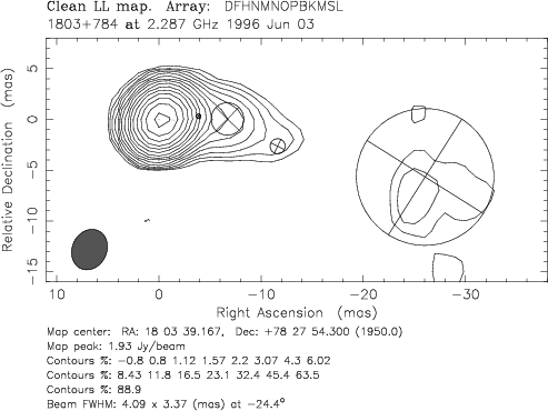
|
Figure 19: Results of hybrid imaging (contours) and circular Gaussian model fitting (circles with crosses) for S5 1803+784 at 2.3 GHz. |
| Open with DEXTER | |
![\begin{figure}
\par\mbox{\subfigure[]{\psfig{figure=9267f20a.ps,width=7.5cm} }
\hspace*{2cm}\subfigure[]{\psfig{figure=9267f20b.ps,width=7.5cm} }}\end{figure}](/articles/aa/full_html/2010/03/aa9267-07/img124.png)
|
Figure 20: Results of hybrid imaging (contours) and circular Gaussian model fitting (circles with crosses) for S5 1803+784 at 1.6 GHz. |
| Open with DEXTER | |
Table 1: Circular Gaussian model-fit results for S5 1803+784. The columns list the epoch of observation, the jet-component identification, the flux density, the radial distance of the component center from the core, the position angle of the center of the component, the FWHM major axis, and the chi-square of the fit.
Table 2: Gaussian model-fit results for S5 1803+784 obtained from the literature. The columns list the epoch of observation, the jet-component identification, the flux density, the radial distance of the component center from the core, the position angle of the center of the component, the FWHM major axis, and for elliptical Gaussian fits, the axial ratio and the position angle of the major axis. The final column provides a reference to the original publication.
Table 7:
Discrete cross-correlations (based on components from the 8 GHz
model fits) and Pearson's correlation coefficients
(from 15 GHz model fits), calculated between the time series
of various pairs of jet parameters and/or the total flux densities.
Column 1 gives the frequency of the analyzed data set; Col. 2
lists the individual jet component from which the parameters to
correlate are taken; Cols. 3 and 4 list the parameters
correlated. For 8 GHz data, the DCF peak and ![]() are the peak of discrete cross-correlation function and the associated
time lag in years. For 15 GHz data, Corr.coeff. is
the value of the Pearson's correlation coefficient, and p is the probability of getting such a high correlation by chance.
are the peak of discrete cross-correlation function and the associated
time lag in years. For 15 GHz data, Corr.coeff. is
the value of the Pearson's correlation coefficient, and p is the probability of getting such a high correlation by chance.
Table 8:
Discrete cross-correlations (based on components from the 8 GHz
model fits) and Pearson's correlation coefficients
(from 15 GHz model fits), calculated for various pairs jet
parameters and the core flux density. Column 1 gives the frequency
of the analyzed data set; Cols. 2 and 3 lists the two jet
components participating in the correlation; Col. 4 shows the
circular Gaussian parameter correlated. When ``core'' is the first
component, its parameter is always flux-density.
For 8 GHz data, DCF peak and ![]() are the peak of the discrete correlation function and the associated
time lag in years. For 15 GHz data, Corr.coeff. is the value
of the Pearson's correlation coefficient, and p the probability of getting such a high correlation by chance.
are the peak of the discrete correlation function and the associated
time lag in years. For 15 GHz data, Corr.coeff. is the value
of the Pearson's correlation coefficient, and p the probability of getting such a high correlation by chance.
Footnotes
- ... 1803+784
- Figures 15 to 20 and Tables 1, 2, 7, and 8 are only available in electronic form at http://www.aanda.org
- ...
- Member of the International Max Planck Research School (IMPRS) for Radio and Infrared Astronomy at the Universities of Bonn and Cologne.
All Tables
Table 3: Linear regression fits to the motion of listed components.
Table 4: Gaussian parameters of outbursts in the UMRAO light-curves.
Table 5: Maxima and minima in flux density, position angle and core separation at epochs 1987, 1988.5, 1990, and 1991 at 8.4 GHz.
Table 6: Maxima and minima in flux density, position angle and core separation at epochs 1998 and 2000 at 15 GHz.
Table 1: Circular Gaussian model-fit results for S5 1803+784. The columns list the epoch of observation, the jet-component identification, the flux density, the radial distance of the component center from the core, the position angle of the center of the component, the FWHM major axis, and the chi-square of the fit.
Table 2: Gaussian model-fit results for S5 1803+784 obtained from the literature. The columns list the epoch of observation, the jet-component identification, the flux density, the radial distance of the component center from the core, the position angle of the center of the component, the FWHM major axis, and for elliptical Gaussian fits, the axial ratio and the position angle of the major axis. The final column provides a reference to the original publication.
Table 7:
Discrete cross-correlations (based on components from the 8 GHz
model fits) and Pearson's correlation coefficients
(from 15 GHz model fits), calculated between the time series
of various pairs of jet parameters and/or the total flux densities.
Column 1 gives the frequency of the analyzed data set; Col. 2
lists the individual jet component from which the parameters to
correlate are taken; Cols. 3 and 4 list the parameters
correlated. For 8 GHz data, the DCF peak and ![]() are the peak of discrete cross-correlation function and the associated
time lag in years. For 15 GHz data, Corr.coeff. is
the value of the Pearson's correlation coefficient, and p is the probability of getting such a high correlation by chance.
are the peak of discrete cross-correlation function and the associated
time lag in years. For 15 GHz data, Corr.coeff. is
the value of the Pearson's correlation coefficient, and p is the probability of getting such a high correlation by chance.
Table 8:
Discrete cross-correlations (based on components from the 8 GHz
model fits) and Pearson's correlation coefficients
(from 15 GHz model fits), calculated for various pairs jet
parameters and the core flux density. Column 1 gives the frequency
of the analyzed data set; Cols. 2 and 3 lists the two jet
components participating in the correlation; Col. 4 shows the
circular Gaussian parameter correlated. When ``core'' is the first
component, its parameter is always flux-density.
For 8 GHz data, DCF peak and ![]() are the peak of the discrete correlation function and the associated
time lag in years. For 15 GHz data, Corr.coeff. is the value
of the Pearson's correlation coefficient, and p the probability of getting such a high correlation by chance.
are the peak of the discrete correlation function and the associated
time lag in years. For 15 GHz data, Corr.coeff. is the value
of the Pearson's correlation coefficient, and p the probability of getting such a high correlation by chance.
All Figures
|
|
Figure 1: Panel a) shows the core separation as function of time, r(t), for those jet components detected at 15 GHz. Individual components are denoted by different symbols and lines (usage common across all panels). Note the straight line for component Ca and the fast moving component B3. Panels b) and c) show r(t) for 8.4 GHz and 5 GHz observations, respectively, based on data collected from the literature, with component re-identification following the new scenario discussed in this paper. Panel d) shows r(t) for components farther out along the jet based on 1.6 GHz observations (new + from the literature). Panel e) shows the motion of component Ca in rectangular coordinates at 8.4 and 15 GHz, in which a displacement towards larger x values is apparent between the fits from the earlier (1986-1994) and newer (1995-2001) 8.4 GHz data with the 15 GHz fits falling in between. Panel f) shows the flux-density along the jet based on all new epochs of the 15 GHz data. The x and y axes scales differ across panels a)- d). |
| Open with DEXTER | |
| In the text | |
|
|
Figure 2: Model fits superimposed on the hybrid maps obtained from Cleaning and self-calibration for the most recently observed five epochs. The component positions are connected by dotted lines. The positions of the fast component B3 are connected by a solid line. Please note that the elapsed time between adjacent epochs differs. |
| Open with DEXTER | |
| In the text | |
|
|
Figure 3: Gaussian decomposition of the UMRAO 14.5 GHz light-curve. The solid line shows the sum of the Gaussian functions and dotted lines are individual Gaussian functions. Letters indicate the names of the flares. |
| Open with DEXTER | |
| In the text | |
|
|
Figure 4: Time lags of individual outbursts as functions of frequency. |
| Open with DEXTER | |
| In the text | |
|
|
Figure 5: Time evolution of the quasi-simultaneous spectral index, fit to the 4.8 GHz, 8 GHz, and 14.5 GHz flux densities. |
| Open with DEXTER | |
| In the text | |
|
|
Figure 6: Position angle as function of time at different frequencies for four individual components. |
| Open with DEXTER | |
| In the text | |
|
|
Figure 7: Time evolution of standard deviation of position angles, calculated for components within 5 mas of the core in 0.3 year bins. Dotted circles show 8.4 GHz data; circles 15 GHz data. |
| Open with DEXTER | |
| In the text | |
|
|
Figure 8: The jet ridge line for all components detected in 15 GHz observations within 6 mas of the core. Panel a) overplots all epochs, as denoted by the different lines/points. Panels b) and c) show the trace of the jet in Cartesian coordinates (left-hand columns) and the flux density along the jet as a function of x (right-hand columns). |
| Open with DEXTER | |
| In the text | |
|
|
Figure 9: Position angle distribution of individual jet components as a function of time. Panels a) and b) show the new observations from this paper and those combined with the observations from the literature, respectively, for all frequencies. Panels c) and d) show components within 5 mas of the core 15 GHz and 8.4 GHz, respectively. |
| Open with DEXTER | |
| In the text | |
|
|
Figure 10: The spread in the position angle for four different frequencies as a function of time, based on all the data (this paper + literature). We clearly find several maxima that are correlated with the maxima found in the total flux-density data. |
| Open with DEXTER | |
| In the text | |
|
|
Figure 11: Total single-dish flux-density light-curve for S5 1803+784 at 4.8, 8 and 14.5 GHz. The 8 and 14.5 GHz light-curves are shifted by 1.5 and 4 Jy, respectively. All the data are from the UMRAO monitoring campaign. |
| Open with DEXTER | |
| In the text | |
|
|
Figure 12: Core separation, flux density, position angle of component C1, and total flux-density light-curve at 8 GHz in the period 1984-1996. The two dashed lines indicate the nearly simultaneous peaks in all four plots. |
| Open with DEXTER | |
| In the text | |
|
|
Figure 13: Panel a) shows core separation as a function of position angle for the brightest component Ca. Panel b) shows the flux density of component C1 against that of component Ca. Both panels plot the parameters estimated from 15 GHz observations from all the different epochs. |
| Open with DEXTER | |
| In the text | |
|
|
Figure 14: Time lag of the discrete cross-correlation function of the core separation of component Ca vs. those of components C0, C1, C21, and C23 as a function of the mean value of distance from the core for these components. The linear regression fit to these time lags is overplotted. |
| Open with DEXTER | |
| In the text | |
|
|
Figure 15: Results of hybrid imaging (contours) and circular Gaussian model fitting (circles with crosses) for S5 1803+784 at 15 GHz. |
| Open with DEXTER | |
| In the text | |
|
|
Figure 16: Results of hybrid imaging (contours) and circular Gaussian model fitting (circles with crosses) for S5 1803+784 at 15 GHz; continuation of Fig. 15. |
| Open with DEXTER | |
| In the text | |
|
|
Figure 17: Results of hybrid imaging (contours) and circular Gaussian model fitting (circles with crosses) for S5 1803+784 at 8.4 GHz. |
| Open with DEXTER | |
| In the text | |
|
|
Figure 18: Results of hybrid imaging (contours) and circular Gaussian model fitting (circles with crosses) for S5 1803+784 at 5 GHz. |
| Open with DEXTER | |
| In the text | |
|
|
Figure 19: Results of hybrid imaging (contours) and circular Gaussian model fitting (circles with crosses) for S5 1803+784 at 2.3 GHz. |
| Open with DEXTER | |
| In the text | |
|
|
Figure 20: Results of hybrid imaging (contours) and circular Gaussian model fitting (circles with crosses) for S5 1803+784 at 1.6 GHz. |
| Open with DEXTER | |
| In the text | |
Copyright ESO 2010
Current usage metrics show cumulative count of Article Views (full-text article views including HTML views, PDF and ePub downloads, according to the available data) and Abstracts Views on Vision4Press platform.
Data correspond to usage on the plateform after 2015. The current usage metrics is available 48-96 hours after online publication and is updated daily on week days.
Initial download of the metrics may take a while.