| Issue |
A&A
Volume 681, January 2024
|
|
|---|---|---|
| Article Number | A49 | |
| Number of page(s) | 26 | |
| Section | Astrophysical processes | |
| DOI | https://doi.org/10.1051/0004-6361/202346920 | |
| Published online | 08 January 2024 | |
The current state of disk wind observations in BHLMXBs through X-ray absorption lines in the iron band
1
Univ. Grenoble-Alpes, CNRS, IPAG, 38000 Grenoble, France
e-mail: This email address is being protected from spambots. You need JavaScript enabled to view it.
2
Dipartimento di Matematica e Fisica, Università degli Studi Roma Tre, via della Vasca Navale 84, 00146 Roma, Italy
3
INAF – Osservatorio Astronomico di Brera, Via Bianchi 46, 23807 Merate (LC), Italy
4
Max Planck Institute fur Extraterrestriche Physik, 85748 Garching, Germany
Received:
17
May
2023
Accepted:
27
July
2023
Abstract
The presence of blueshifted absorption lines in the X-ray spectra of black hole low-mass X-ray binaries is the telltale mark of massive outflows called winds. These signatures are found almost exclusively in soft states of high-inclined systems, hinting at equatorial ejections originating from the accretion disk and deeply intertwined with the evolution of the outburst patterns displayed by these systems. In the wake of the launch of the new generation of X-ray spectrometers, studies of wind signatures remain mostly restricted to single sources and outbursts, with some of the recent detections departing from the commonly expected behaviors. We thus give an update to the current state of iron band absorption line detections through the analysis of all publicly available XMM-Newton-pn and Chandra-HETG exposures of known black hole low-mass X-ray binary candidates. Our results agree with previous studies, as our wind detections are exclusively found in dipping, high-inclined sources and almost exclusively in bright (LX > 0.01LEdd) soft (HR < 0.8) states with blueshift values generally restricted to a few 100 km s−1. The line parameters indicate similar properties between objects and outbursts of single sources, and despite more than 20 yr of data, very few sources have the HID sampling necessary to properly study the evolution of the wind during a single outburst. We provide an online tool with details of the wind signatures and outburst evolution data for all sources in our sample.
Key words: X-rays: binaries / accretion / accretion disks / stars: black holes / stars: winds / outflows
© The Authors 2024
 Open Access article, published by EDP Sciences, under the terms of the Creative Commons Attribution License (https://creativecommons.org/licenses/by/4.0), which permits unrestricted use, distribution, and reproduction in any medium, provided the original work is properly cited.
This article is published in open access under the Subscribe to Open model. This email address is being protected from spambots. You need JavaScript enabled to view it. to support open access publication.
1. Introduction
In X-ray binaries, the accretion of matter from a main sequence star onto a compact object, either a neutron star (NS) or a black hole (BH), produces spectral signatures that peak in the X-ray band. For the subpopulation of low-mass X-ray binaries (LMXBs), this accretion is sustained via Roche Lobe overflow of the K-M spectral type donor star and forms an accretion disk around the compact object. The vast majority of BHLMXBs (the focus of this study) are transients (King et al. 1996; Corral-Santana et al. 2016), alternating between long-term phases of quiescence and brief periods of outburst that last from a few months to a few years. These events are characterized by a rise in luminosity of several orders of magnitude across all wavelengths (Fender et al. 2004; Remillard & Mcclintock 2006), interpreted as the consequence of instabilities due to ionization of hydrogen in the disk (see e.g., Done et al. 2007, for a review). These outbursts show many remarkable spectral and timing properties, especially in the X-ray and radio bands, the most obvious being a common hysteresis pattern between two distinct spectral states (see e.g., Dunn et al. 2010, for a review).
The beginning of an outburst is marked by a rise in the X-ray luminosity of several orders of magnitude. In this phase, the X-ray spectrum is dominated by a hard (Γ ∼ 1.5) power law with an exponential cutoff around 100 keV (Remillard & Mcclintock 2006; Done et al. 2007). This so-called hard spectral state is associated with non-thermal processes in an extremely hot and optically thin plasma close to the BH (the “corona”). At low energies, the spectral energy distribution (SED) is dominated by a component associated with jets, which extends from the radio to the infrared. These hard states also exhibit strong variability rms, with values of several tens of percent in the X-ray band, often accompanied by type C quasi-perdiodic oscillations (QPOs; see e.g., Ingram & Motta 2019 for a review). When the source reaches high luminosities (up to several percent of LEdd1), a state transition occurs in the span of a few days, coinciding with the appearance of type A and B QPOs. The X-ray power law index raises to Γ ≥ 2.5, and the spectrum transitions to being largely dominated by a bump appearing at around 1 − 2 keV. This is commonly modeled as a multi-temperature blackbody and interpreted as the thermal emission of an optically thick and geometrically thin accretion disk extending close to the innermost stable circular orbit (ISCO) of the BH. Concurrently, the radio emission becomes strongly suppressed (see e.g., Fender et al. 1999, 2004; Corbel et al. 2001; Gallo et al. 2003; Coriat et al. 2009), pointing toward a partial or complete quenching of the jet component, and the variability rms is greatly reduced to values of a few percent. After a period of time in this so-called soft spectral state, the luminosity of the source decreases by one to two orders of magnitude, after which the inverse transition happens, bringing the source back to the hard state before a final descent into quiescence.
The physical mechanisms behind this outburst cycle are hardly understood. The transitions can be linked to a shift in the geometry of the disk from a truncated accretion flow, a hot corona, and a jet in the hard state to a disk extending to the ISCO and no jets in the soft state (Gallo et al. 2003). However, the geometry of the hard state is difficult to distinguish with spectral information alone and thus remains heavily debated (although see Krawczynski et al. 2022, for recent X-ray polarization constraints), as the expected accretion configurations (corona, accretion disk) have difficulties reproducing the entire cycle. For instance, the hot plasma required to reproduce the hard state struggles to reach the high luminosities for which the hard-to-soft transition occurs before collapsing (Yuan & Narayan 2014; Dexter et al. 2021). On the other hand, the “cold” accretion disk present in the soft state, such as the standard solution of Shakura & Sunyaev (1973), remains stable well below the accretion rates at which the soft-to-hard transition should occur.
Coincidentally, the description of the jet in itself is far from complete. It is now well admitted that a poloidal magnetic field is needed to produce large-scale jets (e.g., Beckwith et al. 2008) and that they can be powered by two mechanisms. These two processes, namely, that of Blandford & Znajek (1977) and that of Blandford & Payne (1982), extract rotational energy from the BH or its accretion disk, respectively. However, the relative importance of each in the formation of the global accretion-ejection structure remains a very debated question. Numerical simulations of such structures threaded by a large-scale magnetic field around BHs have now become quite standard, with computations on a large number of dynamical timescales (e.g., Narayan et al. 2003; McKinney & Blandford 2009; Ohsuga et al. 2009; Tchekhovskoy et al. 2011; Liska et al. 2018, 2022), but including realistic radiative processes remains a difficult task (see e.g., Liska et al. 2022 for recent results). Direct comparison of these numerical simulations to observational data is thus far from being achieved. On the other hand, stationary, self-similar accretion-ejection solutions threaded by a large-scale magnetic field have been developed for more than 20 yr now (e.g., Ferreira & Pelletier 1993; Ferreira 1997; Zanni et al. 2007). While less general than the previously mentioned GRMHD numerical simulations, they have the advantage of being more easily comparable to observations (see, e.g., Petrucci et al. 2010; Marcel et al. 2018, 2019, 2020). Unfortunately, no matter the numerical approach, even if a few scenarios have been proposed (e.g., Meyer et al. 2000; Petrucci et al. 2008; Begelman & Armitage 2014; Kylafis & Belloni 2015; Cao 2016), none of the current simulations are able to reproduce the hard-to-soft and soft-to-hard transitions observed during the outbursts and/or how it is related to the jet appearance and disappearance.
Nevertheless, jets are hardly the last piece of the puzzle. Starting 25 years ago (Ueda et al. 1998; Kotani et al. 2000), X-ray absorption lines have been detected in a number of LMXBs, mostly with Fe XXV Kα and Fe XXVI Kα transitions. These are the signatures of a new class of outflows that are far from the relativistic speeds of jets but much more massive: winds (see Díaz Trigo & Boirin 2016; Ponti et al. 2016, for reviews). Winds are deeply intertwined with other accretion and ejection processes, their detection being generally mutually exclusive with jet signatures (Neilsen & Lee 2009). They are also generally observed in the soft states of high-inclined BHLMXB, the latter pointing to significant detections mainly along equatorial lines of sight (Ponti et al. 2012). This, combined with an ability to eject matter at rates potentially comparable to, if not higher than, the accretion rate (Ponti et al. 2012), makes their understanding essential to fully grasp the accretion-ejection processes in LMXBs.
However, the picture depicted by the observations is becoming increasingly complex. In the last ten years, X-ray absorption lines have been reported also in some hard state observations of BHLMXBs (Shidatsu et al. 2013; King et al. 2015; Xu et al. 2018a; Reynolds et al. 2018; Wang et al. 2020), sometimes for potentially low-inclined sources (Chiang et al. 2012; Wang et al. 2018; Chakraborty et al. 2021). Meanwhile, a wealth of P-cygni line profiles are being detected, also in the hard state, but this time in the visible band (Rahoui et al. 2014; Muñoz-Darias et al. 2016, 2018, 2019; Jiménez-Ibarra et al. 2019; Cúneo et al. 2020). These findings imply that the wind is also present in the hard state but is preferentially seen at high energies (in the X-rays) in the soft state and at larger wavelengths (in the optical) in the hard state. This new depiction of a state-independent outflow agrees with recent absorption line observations in the optical and infrared wavelengths in the soft state (Panizo-Espinar et al. 2022; see also Sánchez-Sierras & Munoz-Darias 2020) and with observations of simultaneous X-ray and optical absorption lines in the hard state with compatible origin (Muñoz-Darias & Ponti 2022).
In parallel, theoretical, and modeling efforts are starting to catch up with observations. Recent studies have shown that the thermal stability of the ionized material in the wind is heavily dependent on the spectrum of the source (see e.g., Chakravorty et al. 2013, 2016; Bianchi et al. 2017; Dyda et al. 2017; Higginbottom et al. 2020). This supports the idea that thermal instabilities may play a role in the disappearance of the X-ray absorption lines in the hard state, independently of the physical state of the wind (Petrucci et al. 2021). The picture is much less clear during state transitions, however, and thermal instabilities may not be the only process at work (e.g., Gatuzz et al. 2019). Furthermore, for a thermal stability analysis to be applied, photoionization equilibrium must be achieved throughout the wind, a constraint that must be carefully checked (see e.g., Dyda et al. 2017 and other caveats discussed in Petrucci et al. 2021).
Meanwhile, the physical process powering the wind remains widely debated. Unlike active galactic nuclei (AGNs), whose thermal emission peaks in the UV (Proga & Kallman 2002), the disks of BHLMXBs radiate more in X-rays. This rules out line driving as a driving mechanism in XRBs since the wind is expected to be strongly ionized by the illuminating X-ray continuum. The two remaining mechanisms, thermal driving, where the central SED heats up the surface of the disk until the material exceeds its escape velocity (e.g., Begelman et al. 1983; Woods et al. 1996; Done et al. 2018; Tomaru et al. 2023), and magnetic driving, where the material is lifted by large-scale magnetic fields threading the disk (e.g., Konigl & Kartje 1994; Fukumura et al. 2010, 2017; Chakravorty et al. 2016, 2023), are both viable for XRBs and can affect one another (e.g., Proga 2003; Waters & Proga 2018). However, these two driving mechanisms predict very different absorption line properties. Thermal driving is effective much farther away from the BH and thus results in lower outflow velocities, densities, and variability on longer timescales. On the other hand, magnetohydrodynamic (MHD) winds can be produced anywhere on the disk where the magnetization is large enough (e.g., Jacquemin-Ide et al. 2019). Thus, strong wind signatures with high blueshifts, density, and high variability have been traditionally associated with magnetic winds (see e.g., Miller et al. 2006a, 2015a; Trueba et al. 2019).
Nevertheless, numerical simulations of thermal winds (Higginbottom & Proga 2015) and, more recently, of hybrid thermal-radiative winds (e.g., Done et al. 2018; Higginbottom et al. 2018, 2020) are now able to reproduce the observed absorption features with a high degree of fidelity (e.g., Tomaru et al. 2020, 2023). In parallel, spectrum predictions for XRBs from MHD models, which have only been achieved recently (e.g., Chakravorty et al. 2016, 2023; Fukumura et al. 2017), can successfully recreate absorption line features in standard observations (Fukumura et al. 2021). Although these comparisons are only beginning, it is becoming apparent that the quality of current datasets might not allow for these new solutions of MHD and thermal-radiative winds to be distinguished directly due to their wide range of possible signatures. Notably, even for the highest quality observations, both processes now only differ by very fine degrees (Tomaru et al. 2023). Thankfully, the new generation of X-ray telescopes should soon settle the debate (Chakravorty et al. 2023; Gandhi et al. 2022).
Nevertheless, many answers can still be found in the existing observations, and more constraints can be put through with comparisons to much larger datasets. Indeed, observational studies and modeling efforts often focus on either single observations or select samples with very precise analysis or modeling of the existing features, but they mostly focus on observations with the most prominent lines. Moreover, no detailed study of large samples of sources with exhaustive, multi-instrument data coverage have been performed since the seminal work of (Ponti et al. 2012), despite an extensive increase in the number of observations and sources, and a greater understanding of the winds.
In this work, we analyze all XMM-Newton and Chandra X-ray observations of current BHLMXB candidates made public as of October 2022 in order to have a global view of the wind signatures in a large sample of objects and observations. After explaining our sample selection and data reduction in Sect. 2, we detail the process of line detection in Sect. 3. Following this, we present our results in Sect. 4, and discuss some physical implications in Sect. 5 before concluding. More information regarding individual sources will be presented in a separate work. Finally, besides listing the main detection and non-detection of lines in Appendix C, we also provide an online tool2 for both interactive visualization of our results and easy access to all spectral and line parameters obtained in the study (see Appendix A).
2. Observations and data reduction
2.1. Sample and data selection
In order to maximize the number of BHLMXB candidates, we drew our sample from both the BlackCAT (Corral-Santana et al. 2016) and WATCHDOG (Tetarenko et al. 2016) BH catalogs. The BlackCAT catalog has been continuously updated since its release but is voluntarily restricted to transient sources, which is why some archetypal binaries are missing from it but are present in WATCHDOG. The WATCHDOG catalog also includes high-mass XRBs (HMXBs), and after its publication in 2016, some of its sources have been identified as NSs. Thus, our parent sample is composed of 79 sources: 67 from BlackCAT (in which we only exclude Cen X-2 due to a weak position determination and possible mismatch with GS 1354-64, according to Kitamoto et al. 1990) and 12 from WATCHDOG (as 11 of the 23 sources not overlapping with BlackCAT are either HMXBs or NSs).
In this work, we further restrict the analysis to sources with observations from the two X-ray instruments with the highest sensitivity and energy resolution in the iron K band, namely, XMM-Newton’s EPIC pn and Chandra HETG. After selecting spectra with sufficiently high statistics to apply the line detection process (see Sect. 3), we were left with a final sample of 42 sources. Details about their physical properties, previous detections of iron K wind signatures in the literature, and number of exposures in our sample are given in Table 1.
Sources included in our final sample.
We drew the source physical properties (namely, mass, distance, and inclination) primarily from the more up-to-date references of BlackCAT, and we used WATCHDOG otherwise, except when recent updates were found in the literature. In cases where the distance was unknown, we assumed a distance of 8 kpc. As for mass, we used estimates resulting from dynamical measurements; otherwise, we considered a fixed BH mass of 8 M⊙. We stress than only 11 sources in our final sample have been confirmed as BHs through dynamical measurements (and are noted as such in Table 1). We refer to the two cited catalogs for the arguments in favor or against BHs in the other binaries. Among these, we highlight that IGR J17451-3022, whose origin remains very debated and exhibits absorption lines (Bozzo et al. 2016), is still included in BlackCAT, so we include it in our sample.
2.2. XMM-Newton
Data reduction for XMM-Newton observations was performed with the Science Analysis System (SAS3) version 19.1.0, following the standard analysis threads4. Observation data files (ODFs) were reduced with the epproc task.
To optimize the absorption line detection, we maximized the signal-to-noise ratio (S/N) of the final spectra through an automated procedure. We describe the main steps in the following paragraphs.
The automated procedure first extracts an image centered on the sky coordinates of the source from the event files in the 4–10 keV band. It then computes an initial source and background regions. In imaging, the image is fit with a point spread function (PSF) in order to optimize the source localization. The background region is then generated from the largest circular region not intersecting the brightest 2σ of the source PSF in the source and neighboring CCD, with an area between one and two times that of the source region. Whenever the background region rate exceeds 100 times the value of standard blank fields5, its contribution is disregarded. In timing and burst mode, the source region is centered on the brightest column, and the background is always disregarded in order to avoid source contamination.
Following this, the procedure computes the size of the source region and the filtering of high background periods in a self-consistent way to reach the highest S/N. For this, it selects increasingly large circular (rectangular in timing) regions, each of which is independently filtered for good time intervals (GTIs) in order to maximize its individual S/Ns against the background computed previously (following the method of Piconcelli et al. 2004).
The procedure then estimates the pile-up value with epatplot, and, if necessary, excises an increasingly larger circular portion of the source region until the pile-up value falls below 5%6, a level at which no significant effect on the line detection process is expected. We note that the majority of the spectra actually remain below 1%. After an excision, the first two steps are repeated, this time starting with the filtered GTIs and the excised image, in order to refine the region and filtering of the events.
The final step is the extraction of the source and background spectra from the final region files and GTIs, and the generation of response matrices and ancillary response files with the standard SAS tasks arfgen and rmfgen. The source spectra are grouped using the heasoft task ftgrouppha, following the Kaastra & Bleeker (2016) optimized binning.
We note that although recent work has shown that dust scattering halos can significantly alter the broadband SEDs of XRBs (see e.g., Jin et al. 2017, 2019), this effect is smaller at high energies and is not expected to affect the detection of narrow absorption lines. We thus did not apply such corrections in this work for simplicity.
2.3. Chandra
The reduced, science-ready spectra of the first order of all grating observations are publicly available on the Chandra Transmission Grating Data Archive and Catalog (TGCat; Huenemoerder et al. 2011), and observations of BHLMXBs have been recently updated according to recent improvements in data reduction. We only considered the first order spectra and regrouped the products according to the Kaastra & Bleeker (2016) optimized binning. Background spectra were not computed, as they are often contaminated by the PSF wings7.
3. Spectral analysis
To filter out spectra without sufficient S/N necessary to detect absorption lines in the iron band, we applied a predefined count threshold of 5000 counts in the 4 − 10 keV band to both XMM and Chandra exposures. For XMM, simulations of template spectra from soft state SEDs of GRO J1655-40 in the soft state showed that observations fainter than the chosen threshold cannot detect Fe XXVI Kα upper limits below 75 eV, which coincides with the high-end tail of the equivalent width (EW) distribution in our sample and reports in the literature (see Sect. 4.1.1). While such simulations are less straightforward for Chandra HETG, manual inspection of the excluded spectra confirmed that their S/N is always insufficient for detecting lines with EWs below 100 eV at 7 keV. After this final cut, 242 exposures remained: 137 EPIC-pn spectra and 105 HETG spectra.
The line detection process can be split into four main steps. First, a fit of the continuum with a broadband model (Sect. 3.1). Then, a blind search for line features in the high-energy (6–10 keV) band (Sect. 3.2), followed by an incremental fit of the line features in this energy range with the strongest absorption and emission lines expected in this band (Sect. 3.3). Once this is done, a second blind search from the best-fit model (including the lines) checks for the absence of the remaining line features, and finally the true significance of the absorption lines is assessed via Monte Carlo (MC) simulations (Sect. 3.4).
In the following, we used Xspec version 12.12.0 (Arnaud & Arnaud 1996) via Pyxspec version 2.0.5 along with wilm abundances (Wilms et al. 2000) and the Cash statistic (Cash 1979). Uncertainties for all the reported parameters were estimated drawing an MC chain from the final fit using the internal Xspec Chain commands. Due to the great number of spectra to be analyzed and the use of multiple runs during the line detection process, for a given number of free parameters nfree, we only used 2 ⋅ nfree parameters, for 4000 ⋅ nfree steps, discarding the first 2000 ⋅ nfree steps of each chain. Unless specified otherwise, all uncertainties are quoted at a 90% confidence level.
3.1. Broadband modeling
We used a simple fitting procedure in which a list of components is added recursively to converge to the best fit. Adding or choosing a component over its peers is deemed statistically significant through F-tests, with a threshold fixed at a 99% confidence level. For the broadband modelization of the continuum, three components can be combined: a powerlaw, a diskbb, and an absorption component phabs, which is applied to all of the additive components together. As the goal was to obtain a precise (although phenomenological) estimate of the continuum, we initially limited the contamination due to iron band features by ignoring the 6.7–7.1 and 7.8–8.3 keV bands in this step only.
To limit the effect of low energy spurious features, we restricted the broadband fit to 2–10 keV for XMM-pn and 1.5–10 keV for HETG8. While the NH value may not be estimated perfectly with this choice of energy band, notably for sources with low absorption, it still allows for a good measure of the intrinsic unabsorbed 3–10 keV luminosity and 6–10/3–6 keV hardness ratio (HR). Following this, we then fixed the neutral absorption column density in order to perform the blind search in the 4–10 keV range as a second step, which is described in the next section.
3.2. Blind search
Once the continuum was fixed, we carried out a standard blind search of narrow emission and absorption features in the 4–10 keV band. We measured the change in ΔC when adding a narrow (width fixed at zero)gaussian line with varying normalization and energy on the fit and mapped out the resulting 2D ΔC surface in the line normalization-line energy plan. Regions of strong and relatively narrow (< 1 keV) ΔC excess indicated the possible presence of lines. In contrast, broader regions (> 1 keV) of ΔC excess could reflect the limit of our simple continuum fit process.
The Gaussian energy varies between 4 and 10 keV, with linear energy steps of 50 eV for XMM-Newton, which is around a third of the EPIC-pn spectral resolution at those energies9, and 20 eV for Chandra HETG, which is slightly below HETG’s energy resolution at 4 keV and half at 6 keV10. The line normalization was scaled in an interval of [10−2, 101] times the best-fit continuum flux in each energy step, split in 500 logarithmic steps for both positive and negative normalization.
We show in Fig. 1 an example of the result of the procedure for 4U 1630-47, a source well known for its absorption lines. Panels A and B show the spectrum and model after the first continuum fit in the 4–10 keV band and the ΔC map obtained with our blind search procedure. The contours over plotted in black highlight ΔC levels of 68%, 90%, and 99% confidence intervals with two parameters. The position of the “maxima” in ΔC improvement are highlighted for visualization. In this example, the blind search clearly identifies two very significant (more than 99%) absorption features at ∼6.7 and ∼7 keV, compatible with the Fe XXV Kα and Fe XXVI Kα absorption lines, as well as fainter absorption features at higher energies, compatible with the Kβ complex. The significant emission residual identified at 7.5 keV does not seem to affect the absorption regions.
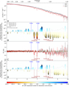 |
Fig. 1. Steps of the line detection procedure for a standard 4U130-47 Chandra spectra. Panel A: spectrum in the 4–10 keV band after the first continuum fit in this band. Panel B: map of the line blind search restricted to positive regions ΔC (i.e., improvements of the fit). Standard confidence intervals are highlighted with different line styles, and the color map shows the ΔC improvements of emission and absorption lines. Panel C: ratio plot of the best fit model once absorption lines are added. Panel D: remaining residuals seen through a second blind search. |
3.3. Line fitting procedure
While the blind search simply gives a semi-quantitative visualization of the possible presence of line-like features in the spectra, the goal of the next step was to identify the main individual absorption lines and to derive their physical parameters. Thus, we started from the continuum fit and added up to seven potential line features using the same F-test threshold as used for continuum components. Among these line features, five were the strongest absorption lines in the iron complex, namely, Fe XXV Kα (6.70 keV)11, Fe XXVI Kα (6.97 keV), Fe XXV Kβ (7.88 keV), Fe XXVI Kβ (8.25 keV), and Fe XXV Kγ (8.70 keV). The two remaining lines are fluorescent emission lines from neutral iron, Fe Kα (6.40 keV) and Fe Kβ (7.06 keV). We did not consider the Ni XXVII Kα and Fe XXV Kγ absorption lines, as they can be blended with the stronger Fe XXV Kβ and Fe XXVI Kβ, respectively, at our resolutions.
We modeled all lines with a simple gaussian component, convolved with vashift in order to allow for a shift of the lines, limited to [ − 10 000, 5000] km s−1. Indeed, we did not expect significantly redshifted absorption lines nor speeds beyond 0.03c, as the vast majority of wind observations up until now have either shown wind speeds compatible with zero or a few thousands of kilometers per second at most (see references in Table 2). Moreover, allowing for higher blueshifts would produce degeneracy between neighboring lines (Fe XXV Kα reaches Fe XXVI Kα’s energy at v ∼ 12 000 km s−1, and Fe XXV Kβ reaches Fe XXVI Kβ at v ∼ 14 000 km s−1). We assumed that all lines of a single ion are produced in the same region of the wind and consequently have the same velocity shift. All absorption lines were considered narrow, allowing their width to vary only up to σ < 50 eV. A line is considered resolved only if its width is larger than zero with a 3σ level of confidence.
Details of accretion states with reports of absorption line detection in both our work and the literature.
While we are not interested in characterizing emission lines in detail, a good portion of observations show significant broad emission features in the iron region, which we modeled using up to two simple phenomenological neutral Fe Kα and Fe Kβ broad gaussian components, restricting their blueshift to the same interval taken for absorption lines and limiting their widths to [0.2, 0.7] keV. The lower limit prevents overlapping between narrower emission and absorption features, while the upper limit prevents the broad emission features from modeling large parts of the continuum.
In very few XMM observations of GRS 1915+105 and GRO J1655-40, however, such as the exposures analyzed in Trigo et al. (2007), the presence of extreme emission features requires more complex modeling. For these spectra, we followed the same approach as Trigo et al. (2007), using a laor component with energy free in the range of [6.4–7.06] keV, inclination in the range of [50–90] degrees (consistent with the highly inclined sources ), and Rin and Rout fixed at their default values.
We show in panel C of Fig. 1 an example of the result of the procedure for a standard observation. In this case, all five Fe absorption components are sufficiently significant to be added in the model and reproduce the absorption features very well. Nevertheless, once the line fit was complete, we performed a second blind search to check the presence of the remaining line features in the residuals, following the procedure described in the previous section. We show in panel D of Fig. 1 the result of this step for our example spectra. While all five main absorption features are indeed perfectly reproduced, a significant narrow feature at ∼8.1 keV remains, which can be identified with the Kα transition from Ni XXVIII. Similar residual features are only found in the highest S/N Chandra spectra, suggesting the presence of other weaker transitions not included in our five main components. However, these further absorption features are present only in combination with the much stronger lines considered in our analysis, but their detailed characterization is beyond the scopes of this paper.
For all the observations with no detected absorption lines, we computed the 3σ (99.7%) upper limit of each line’s EW using the highest value in the line’s range of velocity shift. All EW measurements and upper limits are reported in Table C.1.
3.4. Line significance assessment
The goodness-of-fit and F-test methods have long been known to overestimate the detection significance of lines (Protassov et al. 2002). Reliable estimates can only be obtained through MC simulations (Porquet et al. 2004), which have been adopted as the standard since the last decade (Tombesi et al. 2010; Gofford et al. 2013; Parker et al. 2020; Chartas et al. 2021). We follow a similar procedure, adopting the same methodology as for the real data by putting similar constraints in energy and width as described in Sect. 3.3.
We thus generated 1000 distributions of parameters within the uncertainties of the final model from 1000 runs of the simpars xspec command. We then deleted all absorption line components from the models before repeating the following steps for 1000 iterations.
First, we loaded a set of model parameters from the simulated distribution. We then simulated a spectrum from the current model using the fakeit xspec command, retaining all of the observational parameters (exposure, response files, background) of the initial spectrum. After that, we fit the continuum plus emission lines model to the simulated spectrum in order to obtain a baseline C-stat. This allowed for the computation of the maximum possible ΔC gained from the addition of an absorption line in each line’s allowed blueshift bands (exactly as done for the real data; described in Sect. 3.3).
The ΔC of the line detected in the real data can be compared to the distribution of the 1000 maximal ΔCsim of the simulated spectra, and the statistical significance of the line is defined by P = 1 − N/1000, with N being the number of ΔCsim larger than the real value. Only lines with a significance larger than 3σ (99.7%) in their blueshift range, as derived from this procedure, are considered detections and are considered as such in the following sections, as well as reported in Table C.1.
4. Global results
The hardness intensity diagram (HID) of the full sample is shown in Fig. 2. Despite a sample of 42 sources, absorption line detections remain restricted to only a very small subset of objects, namely, the highly inclined 4U 1630-472, GRO J1655-40, GRS 1915+105, H 17432-322, and IGR J17451-3022 (IGRJ17451 hereafter). The detections follow the same trend as previously reported in Ponti et al. (2012) without any detection in “pure” hard states (corresponding to HR ∼ 1; see Sect. 4.2 for details). In the case of GRS 1915+105, which does not follow the standard outburst evolution, absorption lines are generally detected when the jet is quenched, with one single exception for ObsID 660 (Lee et al. 2002 and see Neilsen & Lee 2009; Neilsen et al. 2012 for details).
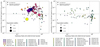 |
Fig. 2. Hardness intensity diagram with the position of all line detections in the sample. The sample is split according to the viewing angle: the left panel is restricted to dippers, or sources, with i > 55°, while the right panel shows all other sources. The vertical and horizontal lines highlight the luminosity and HR thresholds proposed in Sect. 4.2. |
4.1. Parameter distribution and correlation
To study the behavior of the absorption lines and their interplay with the continuum SED in more detail, we analyzed the distribution of their main parameters and identified statistically significant correlations. To identify the correlations between individual parameters, we computed the Spearman coefficients, which trace general monotonic relations between two parameters. For that purpose, and in order to take into account the uncertainties of each parameter, we applied MC simulations to estimate the distribution of the correlation coefficients and associated p-values, following the perturbation method of Curran (2014). This was implemented through the python library pymccorrelation (Privon et al. 2020). In the following subsections, we focus on all correlations with p < 0.001 found in our sample.
4.1.1. Parameter distribution
We assessed the main properties of the absorption features in our sample with the detection of each line, their EWs, and the velocity shifts for the better constrained Kα complex. The distributions are presented in Fig. 3. The data in the left panels are split by source in order to show the properties of the absorption features in each object, but we stress that except for a few outliers, which are discussed below, the number of detections is too limited for the differences between the distributions to be significant. The data in the right panels, which are instead split by instrument, should exhibit mostly similar distributions, as XMM-Newton and Chandra observed similar portions of the HID. This is clearly the case for the distribution of line detections: both instruments show the largest number of detections for Fe XXVI Kα, followed by Fe XXV Kα, Fe XXV Kβ, and Fe XXVI Kβ. Moreover, no Kβ or Kγ lines are detected without the corresponding Kα. In addition, as can be seen in the list of detections in Table C.1, the Fe XXVI Kα line is present in nearly all observations where lines are detected, except one where only Fe XXV Kα was detected. Meanwhile, the single significant detection of Fe XXV Kγ is found in a Chandra spectrum.
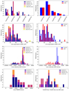 |
Fig. 3. Distribution of intrinsic line parameters (detections of each line, EW, blueshift, widths, and Kα EW ratio) for the entire sample. The parameters are split by source and instrument whenever relevant. The blueshift distributions are restricted to the Kα complex. |
Although less apparent, the distribution of the EWs of both instruments are also broadly compatible, with a KS test p-value of 0.46. The whole sample spans a range of ∼5 − 100 eV, with XMM detections expectedly dropping below 15 eV due to more limited energy resolution. The EW ratio between the Fe XXVI Kα and Fe XXV Kα line (hereafter called Kα EW ratio) provides a proxy of the ionization parameter ξ in our sample (e.g., Bianchi et al. 2005). As seen in the bottom-right panel in Fig. 3, in our sample, the majority of the Kα EW ratios are clustered between 1 and 2.5. This means that most exposures with line detections have sufficiently high ionization parameters for the Fe XXVI Kα line to be predominant. However, two objects (namely, GRS 1915+105 and GRO J1655-40) show Kα EW ratios also spread across the entire observed range, with a number of detections significantly below 1 associated with a lower ξ.
The velocity shift distributions for the strongest Kα lines are clearly different between the two instruments, with a KS test p-value of 1.7 × 10⁻⁷ (see bottom-right panel of Fig. 3). In particular, XMM-Newton showed a somewhat uniform distribution between −6500 and 2000 km s−1, while the Chandra velocity shift distribution is much narrower and more symmetric around zero. The highest blueshift obtained with Chandra is around 1200 km s−1, which is in accordance with the highest values previously reported in the literature for this observation (Miller et al. 2008).
This difference between the instruments can be at least partly attributed to the limits of the EPIC-pn camera. Indeed, in the timing mode used for the vast majority of EPIC-pn observations in our sample, even after recent updates in energy-scale calibration12, the energy accuracy remains limited, with a residual average shift of 18 eV (∼800 km s−1 for Fe XXVI Kα) and a standard deviation of 80 eV (∼3500 km s−1 for Fe XXVI Kα) at 12 keV. The standard deviation of our measured distribution is ∼2500 km s−1 and is thus compatible with the theoretical limits of the instrument’s accuracy (which we can expect to be somewhat better at 7 keV). The mean value of our measured distribution is also ∼2500 km s−1, and it is significantly larger than the mean of post-calibration systematic energy accuracy. However, this may be the consequence of our choice to restrict the allowed blueshift fitting range to [−10 000, 5000] km s−1, which would introduce a bias in a distribution with such a significant spread. In addition, this large average blueshift cannot be reconciled with the much smaller measurement of the more accurate Chandra-HETG instrument, so we only consider the Chandra blueshifts in the rest of the paper.
The observed Chandra velocity shift distribution is within the expectations from a sample of intrinsically zero-velocity absorption lines with an average value of μ ∼ 60 ± 100 km s−1 and a standard deviation of σ ∼ 630 km s−1. However, few observations have significant velocity beyond 2σ of the mean of this distribution. We report in Fig. 4 the scatter plots of the Chandra velocity shifts of the Fe XXV Kα (left panel) and Fe XXVI Kα (right panel) lines against the 3–10 keV luminosity in Eddington units, which highlights that the three faintest GRS 1915+105 exposures are the only ones to show significant Fe XXV Kα positive shifts (i.e., redshifts). However, the Fe XXV Kα absorption line profiles observed in these three cases exhibit unusually asymmetric and broad absorption features (see the data panels of Fig. B.1), while the Fe XXVI Kα lines energies are consistent with zero velocity.
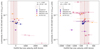 |
Fig. 4. Scatter plot of the Fe XXV Kα (left) and Fe XXVI Kα (right) velocity shifts against luminosity in Chandra observations. The scatter plot is color coded according to the sources. The gray dotted line corresponds to zero velocity and the brown line to the mean of the curated Kα blueshift distribution, whose standard deviation is visualized by the brown region. The biased Fe XXV Kα blueshifts measured in the obscured GRS 1915+105 observations, which are excluded from this distribution, are marked in dashes. |
According to Neilsen et al. (2020), this apparent redshift might be caused by contributions from lines at lower energies blended with Fe XXV Kα. We verified this with a simple fit with two photoionized slabs13, which we show in the lower panels of Fig. B.1. We found that the highest ionization component (log(ξ)∼5 − 6) models the Fe XXVI Kα and part of the Fe XXV Kα lines that show a blueshift ∼ − 250 km s−1, while a lower ionization phase (log(ξ)∼2.5 − 3) at zero velocity produces some of the Fe XXV Kα line but is also heavily affected by the absorption lines from Fe XXI to Fe XXIV, which reproduce the observed “redshifted” tail of the line profiles. We thus excluded these three observations from the velocity shift distribution, changing the distribution average to μ ∼ −200 ± 60 km s−1 and reducing the standard deviation to σ ∼ 360 km s−1, as highlighted in Fig. 4.
With this restriction, the only remaining outlier (more than 2σ away from the restricted mean) is found in the blueshifted Fe XXVI Kα line of the exceptional absorption signatures of GRO J1655-40’s 2005 outburst (Miller et al. 2006a) and is in agreement with the extreme absorption features displayed in this observation (see Miller et al. 2008 for a detailed study). We note that one exposure of 4U 1630-47 (obsid 13716) remains at the tail end of the Fe XXV Kα velocity shift distribution, with a redshift of 500 km s−1. This blueshift measurement is distinct from zero at more than 3σ as well as from the corresponding Fe XXVI Kα line (itself with a blueshift of ∼300 km s−1). This result can once again be explained by contamination from a lower ionization component, in line with more in depth analysis, such as the work of Trueba et al. (2019), who modeled the outflow with two photoionization components. In this observation, both components show a significant decrease in the ionization parameter compared to rest of the coverage of the outburst while maintaining low, negative velocity shifts, in accordance with our results for the other exposures.
The mean value of −200 ± 60 km s−1 is very low compared to the standard Chandra-HETG absolute wavelength uncertainty of ±0.006 Å14, which translates to ∼ ± 1000 km s−1 at the Fe XXVI Kα energy (∼300 km s−1 at 2 keV). However, empirical studies have shown that the “effective” absolute wavelength accuracy of HETG is significantly better and reaches ∼25 km s−1 at energies below ∼2 keV (Ishibashi et al. 2006; Bozzo et al. 2023). This has been corroborated by other works making use of very precise spectral features (Ponti et al. 2018). The few existing BH wind studies that consider the effective HETG accuracy also estimate it to be up to 50–100 km s−1, depending on the line considered (see Miller et al. 2020; Muñoz-Darias & Ponti 2022). Thus, our sample is likely to exhibit a significant global blueshift, in agreement with the common association of these absorption lines to outflowing winds, although the average velocity is very low.
It is also possible to measure the widths of the of Fe XXV Kα and Fe XXVI Kα lines in the Chandra observations with the highest S/N. The distribution of the full width at half maximum (FWHM) of the 21 lines with significant width measurements is reported in the lower-left panel of Fig. 3. While all significant line width measurements are in the 1500–5000 km s−1 range, the highest values, found in the three GRS 1915+105 exposures with contamination from other line complexes discussed above, are probably overestimated.
4.1.2. Significant correlations
The first significant correlation we found in our results is between the width and EW of the Fe XXV Kα line (p ≤ 0.0002), which we show in Fig. 5 and contrast with the absence of correlation in the case of Fe XXVI Kα. Such a correlation may naturally arise because larger turbulence velocities delay the saturation at the line center, allowing the EW to grow to larger values (see e.g., the curve of growths presented in Bianchi et al. 2005). Moreover, the saturation itself at high column densities contributes to broadening the absorption lines. To test these effects, following the methodology detailed in Bianchi et al. (2005), we computed the curve of growths for Fe XXV Kα and Fe XXVI Kα lines as a function of the corresponding ionic column densities Ni and different turbulence velocities. Moreover, we estimated the FWHM of each computed profile relative to the given Ni (and therefore EW) and velocity. These computations allowed us to derive the theoretical curves superimposed on the data plotted in Fig. 5.
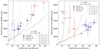 |
Fig. 5. Scatter plot of the EW and width for the Fe XXV Kα (left) and Fe XXVI Kα (right) lines in Chandra observations. The curves highlight the theoretical evolution of these parameters for a range of ionic column densities of the respective ions. |
All measurements of the Fe XXV Kα and Fe XXVI Kα lines are compatible with the expectations because the lines appear in the allowed portion of the parameter space. Indeed, the lower-right corner of the plots in Fig. 5 are expected to be unpopulated since the EW saturates at large Ni and cannot grow further while the line width continues to rapidly increase. On the other hand, we would also expect observations to populate the upper-left corner, but there is likely a strong observational bias against broad lines with low EW. We find it is interesting to note that lower ionic column densities are needed for the majority of observed Fe XXV Kα lines with respect to Fe XXVI Kα, suggesting an average high ionization parameter, in accordance with the typical large Fe XXVI Kα/Fe XXV Kα EW ratio noted before in our sample. The few detections with the highest Fe XXV Kα EWs require higher Fe XXV ionic column densities and thus a lower ξ, in accordance with their lower Fe XXVI Kα/Fe XXV Kα EW ratios.
We also observed a significant anti-correlation between the Fe XXV Kα EW versus the X-ray luminosity, as shown in the left panel of Fig. 6. We find it is worth noting that the p-value remains below 10−5 even without including the uncertain luminosity measurement of IGR J17451-3022. This anti-correlation may naturally arise if we take the luminosity as a proxy for the ionization parameter (i.e., assuming a universal nr2 factor for the whole sample), and this is indeed what is expected if the average ionization parameter is just above the peak of the ionic fraction for Fe XXV (e.g., Bianchi et al. 2005). In comparison, no such correlation was observed for the Fe XXVI Kα line (see right panel of Fig. 6), as expected since its ionic fraction would instead be at its peak for the same ionization parameter. An equivalent way to show these different behaviors is via the significant correlation between the X-ray luminosity and the Fe XXVI Kα/Fe XXV Kα EW ratio for all the observations where both lines are detected (see Fig. 7). This ratio is expected to be a monotonic function of the ionization parameter (e.g., Bianchi et al. 2005) and should thus correlate with luminosity.
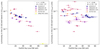 |
Fig. 6. Scatter plot of the Fe XXV Kα (left) and Fe XXVI Kα (right) EW against luminosity for the entire sample. The scatter plot is color coded according to the sources. |
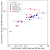 |
Fig. 7. Scatter plot of the Fe XXVI Kα/Fe XXV Kα EW ratio against luminosity for the entire sample. |
4.2. Favorable conditions for absorption line detections of Fe XXV and Fe XXVI in this sample
Our HIDs in Fig. 2 show that absorption lines of He-like and H-like iron are mainly observed in luminous soft states of highly inclined sources. Indeed, we may further propose quantitative thresholds to define a “favorable” region for this type of wind detection based on the Hardness Ratio, inclination, and luminosity.
Our first observation is that all absorption line detections in our sample occur below an HR (computed using unabsorbed flux) of HR[6 − 10]/[3 − 10] = 0.8. This cut nevertheless remains arbitrary because it depends on the black body temperature, which is affected by the mass and spin of the objects and, as such, is expected to differ for each source. This cut also does not restrict to pure soft states, as this threshold also includes observations in soft-intermediate and hard-intermediate states. The two most notable exceptions are the two hardest detections in our sample, and they are both exposures of the peculiar GRS 1915+105. One is in a bright, hard jet-emitting state Klein-Wolt et al. (2002), which is referred to as the χ state in Lee et al. (2002), whose wind signatures are normally undetected, although most χ state observations have a much higher HR (see Neilsen & Lee 2009). The other exposure occurred during a recent transition to a new obscured state in which the source has spent the majority of the past few years (Miller et al. 2020). In this second observation, the observed HR is not an intrinsic property of the SED but mostly an effect of absorption. A less conservative limit on the “soft” wind emitting states could be close to HR[6 − 10]/[3 − 10] = 0.7 when these two observations are excluded. We note that the absorption line detections in sources other than GRS 1915+105 are generally softer (HR[6 − 10]/[3 − 10] < 0.5), although this might simply be the result of a lack of both softer GRS 1915+105 exposures and harder (but still below the previously defined threshold) observations for other sources, at least with Chandra and XMM.
Focusing on the inclination, we note that the five objects with detections of absorption lines, 4U 1630-47, GRO J1655-40, GRS 1915+105, H 17432-322, and IGR J17451-3022, are all dippers (see Table 1), among which two, GRO J1655-40 and IGR J17451-3022, are eclipsing binaries (Bailyn et al. 1995; Bozzo et al. 2016). Dipping behavior is traditionally associated with high-inclination systems (Motta et al. 2015), and all independent inclination estimates for these five objects agree with values larger than 55 degrees. While estimates are too uncertain to propose this as a precise threshold, it suggests that the detection of X-ray wind signatures is restricted to the inclination range of dippers.
Notably, none of the few non-dipping sources with inclination measurements below 55° show absorption lines (see right panel of Fig. 2). However, the coverage of the soft state is very limited in these objects, and few sources have stringent upper limits. More importantly, none of the remaining objects has a precise dynamical inclination measurement that does not conflict with reflection estimates. Thus, while dipping sources are definitely more prone to detection, better coverage of low-inclined sources (and consensus on inclination estimates) would be preferred in order to conclude whether they are truly exempt from detection.
Finally, there are only two detections below LX ∼ 0.01LEdd. One is from IGR J17451, whose true Eddington ratio is highly uncertain, as both its mass and distance are unknown, and the second is found in the faintest exposure of GRS 1915+105, whose luminosity is probably underestimated, as it is in a semi-obscured state (Miller et al. 2020). This lack of detections below a certain luminosity threshold thus points to a certain Eddington ratio as a requirement to produce highly ionized iron absorption lines. However, our coverage of lower luminosity soft states is very limited, both in terms of number of sources and sampling. This, combined with the intrinsically worse S/N (and thus a lack of constraining upper limits), prevents any definitive conclusion.
4.3. Non-detections in favorable conditions
The presence of non-detections and stringent EW upper limits (< 5 eV) in the wind-favorable region shown in the left panel of Fig. 8 indicate that luminous soft states of high-inclined sources do not necessarily show absorption lines. Among the sources with detections, 4U 1630-47, GRS 1915+105, and H 17432-322 have luminous soft state exposures without absorption lines, as can be seen in more detail in the left panel of Fig. 9.
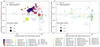 |
Fig. 8. Hardness intensity diagram with the position of all detections in the sample and Fe XXVI Kα upper limits when no line was detected. The diagram uses the same inclination split as in Fig. 2. The vertical and horizontal lines highlight the luminosity and HR thresholds proposed in Sect. 4.2. Sources with no inclination measurements in the right panel are shown with dashed markers. |
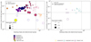 |
Fig. 9. Hardness intensity diagrams of subsamples with relevant non-detections. Left panel: zoom on sources with detection and Fe XXVI Kα upper limits when no line was detected. Right panel: sources with constraining upper limits in the favorable zone (discussed in Sect. 4.3). |
The source with the greatest number of observations, GRS 1915+105, does not follow the standard state evolution and instead evolves erratically in a limited part of the HID. Most of the lower EW upper limits obtained for this source concern observations with larger HR and luminosity than observations with detection, but there is at least one observation, with HR ∼ 0.5, with a very stringent absorption line EW upper limit. This limit, being even lower than the absorption line EWs observed in all neighboring detections, suggests different physical conditions for the wind between these observations, despite a similar SED. This behavior also reflects in the well known rapid variability of the lines themselves in this object (see e.g., Lee et al. 2002; Neilsen et al. 2011, 2020).
In the case of 4U 1630-47, there are at the least three exposures, ObsIDs 14441, 0670673201, and 15511, with stringent upper limits of 14, 7, and 8 eV, respectively (see Table C.1 for details). Only observation 14441 is harder than the cluster of exposures with detections in this source. We note the detection of a single, marginally significant (98.8% significance in the F-test) unidentified absorption feature at 7.8 keV in the third observation. Finally, H 17432-322 shows a single, very significant upper limit of 9 eV in ObsID 3804, which is relatively harder spectrally but remains both very soft and close (both in time and spectral distribution) to the three other detections in its 2004 outburst.
We also note that while GRO J1655-40 shows absorption lines in both of its soft state observations, the number of lines, parameters, and EWs are far more different than what could be explained by evolution in SED alone. This indicates extreme changes in the wind structure and possibly two distinct mechanisms (Neilsen & Homan 2012).
However, it is also important to assess whether non-detection in other dipper and high-inclined sources in the favorable zone are sufficiently significant. To aid readability, we highlight the three sources with no detection despite stringent upper limits in this zone, 4U 1543-47, Swift J1658-4242, and XTE J1817-330, in the right panel of Fig. 9. For 4U 1543-47, it is possible that the lack of lines is due to over-ionization stemming from the extreme luminosity of this source, which is the brightest observed in our sample at LX/LEdd ∼ 0.45. We note that the bolometric luminosity of this source is expected to have surpassed the Eddington limit at the peak of its outburst, as seen by NICER and NuSTAR (Prabhakar et al. 2023). Another explanation could be that the peculiar dips detected in the source (Park et al. 2004) are not a consequence of high inclination. This would reconcile the geometry with the very low angle inferred from dynamical measurements (Orosz et al. 1998; Orosz 2003) and the optical features reminiscent of low inclination recently detected in this source (Sánchez-Sierras et al. 2023b). This would explain the lack of absorption lines.
The same could be said for XTE J1817-330, which has a few stringent absorption line EW upper limits but no inclination constraints and lacks an actual mass estimate. We find it is worth noting that this source was even reported as being low inclined in previous works (Ponti et al. 2012), but it lacks proper inclination measurements, and comparisons of its outburst evolution identify it with sources with mid- to high-inclination measurements (Muñoz-Darias et al. 2013), in agreement with reports of erratic dips (Sriram et al. 2012). Finally, Swift J1658-4242, the only source with clear dipping behavior and no contradictory inclination measurement, shows a range of exposures with stringent upper limits at HID positions very close to detections in other sources. However, the lack of constraints on both its mass and distance prevents any definitive conclusion. Moreover, all constraining exposures are XMM observations with strong relativistic emission in the iron band, which are very complex to disentangle from possible absorption features and could completely hide a weak wind signature due to the limited spectral resolution of XMM.
5. Concluding remarks
Our present study of Fe XXV and Fe XXVI absorption lines in all publicly available XMM-pn and Chandra-HETG observations of BHLMXB candidates yields results in good agreement with previous findings. All the wind signatures we found occur in luminous (LX > 0.01LEdd) soft states (HR[6 − 10]/[3 − 10] < 0.8) of five dippers: 4U 1630-472, GRO J1655-40, GRS 1915+105, H 1743-322 and IGR J17451-3022. Existing inclination measurements are consistent with this behavior, with i > 55° in these five sources.
With the Chandra instrument, which proves to be the only instrument sufficiently precise to reliably measure the outflow velocity, the absorption signatures show a global trend of very small blueshifts. Indeed, the velocity shifts of our sample are on the order of minus a few hundreds of kilometers per second, with a mean of −200 ± 60 km s−1. Moreover, only one detection (in GRO J1655-40) is significantly (> 2σ) below −1000 km s−1. These values, although closer to the limits of HETG’s absolute wavelength accuracy, remain consistent with past publications and in particular with velocity shift measurements in lower energy lines (compared to Fe XXV and Fe XXVI), where HETG’s accuracy is more well studied (see e.g., Ueda et al. 2009; Trueba et al. 2019 and references therein). Other works claiming higher blueshift values employ more complex fits using several photoionization models (see e.g., Miller et al. 2015a), and those works should not be directly compared to our results, although the main ionization zones generally remain in agreement with our findings.
We also obtained good constraints on a few line widths, with FWHMs on the order of a few thousands of kilometers per second for the broadest ones. The observed correlation between the line widths and Fe XXV Kα EW naturally arises in the presence of significant turbulence velocity in the wind, of the order of thousands kilometers per second when assuming a simple slab geometry (see Sect. 4.1.2). Reality is expected to be more complex, possibly with a radial distribution of density and velocity. A more precise modeling is certainly needed to better characterize the amount of turbulence.
We detected a very significant anti-correlation between the X-ray luminosity (in Eddington units) and the line EW in the case of Fe XXV, while no significant correlation was observed in the case of Fe XXVI. This anti-correlation is present in single objects with multiple line detections but also in the entire set of sources showing absorption lines. Although already found in the past in more restricted datasets (Miller et al. 2020; Ponti et al. 2012), such a correlation observed in a sample of different sources would suggest a similar wind structure (i.e., a similar nR2 factor) from source to source at a given LX/LEdd. This anti-correlation would then be expected if the wind ionization is on average above the peak of the ionic fraction for Fe XXV Kα. While it predicts quite large Fe XXV Kα EWs (∼100 eV) below our threshold of 0.01LEdd, the ionization at these luminosities could also go beyond the peak of the Fe XXV Kα ion fraction and shift to producing weaker lines from less-ionized ions. If this is not the case, the lack of detection at low flux may also be due to lower statistics or sparser coverage, but it could also be related to the physical processes producing the wind (e.g., thermal driven wind requiring high illuminating luminosity; Done et al. 2018; Tomaru et al. 2019).
The absence of Fe XXV and Fe XXVI absorption line detection in virtually all hard states in our sample agrees with recent theoretical studies, suggesting that the ionization range compatible with these ions could be thermally unstable when the gas is illuminated by a hard state SED (e.g., Chakravorty et al. 2013, 2016; Bianchi et al. 2017; Petrucci et al. 2021). Thus, even if the wind itself were present, it would not be detectable through Fe XXV and Fe XXVI absorption lines.
There have been recent reports in the literature of a few absorption line detections in hard states of different sources, as shown in Table 2, where we list the reports of absorption lines in all wavebands and associated accretion states for sources in the sample. However, we must stress that the vast majority of these detections come from NuSTAR spectra blended with reflection. The limited spectral resolution of this instrument combined with the model-dependent nature of the residuals of reflection components means that special care should be put into computing the significance of these lines, especially when different reflection models disagree on their existence (see e.g., Chakraborty et al. 2021 and Jia et al. 2022 for MAXI J1348-630). In the meantime, other reports are either not well documented (Reynolds et al. 2018; Saha et al. 2021) or are associated with static or infalling material (Shidatsu et al. 2013), and the only clear iron band hard state detections come from non-standard states of GRS 1915+105 and V404 Cyg (Lee et al. 2002; Muñoz-Darias & Ponti 2022).
The lack of standard X-ray detections in the hard state is still compatible with the increasing number of optical and infrared absorption line detections in hard states seen in Table 2, which suggest that the outflow persists independently of the spectral states (see Panizo-Espinar et al. 2022 and references therein). They arise from the same category of high-inclined (mostly dipping) sources, except in the case of GX339-4, and provide different and complementary views of the outflow, namely, visible lines are restricted to hard states, while infrared detections have been obtained in the whole outburst. However, these detections generally have blueshifts in the range of a few 1000 km s−1, which is significantly higher than in X-rays. More critically, only two sources have clear reports of detection both in the X-rays and in the optical or infrared: V404 Cyg and MAXI J1803-298. As of now, only the first source has been studied in detail, and it shows properties consistent with being produced by the same outflowing material (Muñoz-Darias & Ponti 2022), although in an obscured state with extremely strong emission lines and with short-term variability of absorption features in the iron band, which prevented the detection of absorption lines with our simple procedure.
It is difficult to assess whether the lack of common X-ray and optical or infrared absorption line detections is meaningful. In our study, the vast majority of sources with these features have very poor X-ray coverage in the favorable region. However, several objects have been extensively followed by other X-ray telescopes, such as MAXI J1820+070 with NICER, with only a single tentative report of X-ray absorption detections up to now (Fabian et al. 2021). On the other hand, the sources with X-ray detections in our sample lack either the optical counterpart or the high-quality optical data necessary to search for absorption lines. It is also possible that the physical conditions favoring X-ray and optical wind signatures do not perfectly match (see e.g., Koljonen et al. 2023), but more simultaneous optical and X-ray campaigns are required to draw conclusions.
The results of this paper show that we can only put limited constraints on the evolution of the absorption lines with the current scarce sampling of each outburst. In this regard, the use of the new generation of telescopes with better monitoring capabilities, such as NICER, or of the next evolution of spectrometers, such as XRISM and Athena, will be paramount in separating the outflow evolution from the influence of the SED. We are currently performing a similar analysis on the NICER archive, which remains, for the most part, unpublished.
Through the analysis of the line parameters and HID positions, we also highlight some of the most critical exposures currently available, whose well constrained and extreme or variable wind signatures should be compared against existing and upcoming wind models. In order to improve the current lack of coupling between disk and wind modeling, our next work will compare joint continuum and magnetic wind solutions arising from the JED-SAD framework (Jacquemin-Ide et al. 2019) to the sample analyzed in this work.
Finally, this work has not delved into the details of the behavior of each source. Although the results are directly available through the visualization tool, we will address the most interesting sources individually in a follow-up paper. We will both compare their behavior with the global sample and highlight notable results in unpublished observations.
The Eddington luminosity LEdd is defined as the maximum isotropic emission above which the radiation pressure evens out the gravitational force of the source, stopping the accretion.
Obtained from https://www.cosmos.esa.int/web/XMM-Newton/bs-countrate
Up to 7% was accepted for four exposures, highlighted in Table C.1.
In HETG exposures in timed mode, there can be issues with event resolution at high energy due to an overlap between the default HEG and MEG spatial masks. Thus, whenever necessary, we restrict the upper limit of all energy bands to 7.5 keV, so as to minimize the effect on the continuum while keeping the ability to at least analyze lines of the Kα complex.
The energy of the Fe XXV Kα line was set equal to the resonant transition because the intercombination line is significantly weaker. Neither XMM-epic nor HETG were able to resolve the two lines without extremely high statistics.
See bottom-right panel of Fig. 3 in https://xmmweb.esac.esa.int/docs/documents/CAL-SRN-0369-0-0.pdf
We used the same CLOUDY absorption table model described in Ratheesh et al. (2023).
https://streamlit.io/
Acknowledgments
Part of this work has been done thanks to the financial supports from CNES and the French PNHE. S.B. and M.P. acknowledge support from PRIN MUR 2017 “Black hole winds and the baryon life cycle of galaxies: the stone-guest at the galaxy evolution supper”. S.B. acknowledges support from the European Union Horizon 2020 Research and Innovation Framework Programme under grant agreement AHEAD2020 n. 871158. G.P. acknowledges financial support from the European Research Council (ERC) under the European Union’s Horizon 2020 research and innovation program “HotMilk” (grant agreement No. 865637) and support from Bando per il Finanziamento della Ricerca Fondamentale 2022 dell’Istituto Nazionale di Astrofisica (INAF): GO Large program. This works uses data obtained from the Chandra Data Archive and software (CIAO and TGCat) provided by the Chandra X-ray Center (CXC), as well as data obtained through the HEASARC Online Service, provided by the NASA/GSFC, in support of NASA High Energy Astrophysics Programs. We especially thank the Chandra, TGCat and XMM helpdesks for their help and availability.
References
- Arnaud, K. A., & Arnaud, A. K. 1996, ASP Conf. Ser., 101, 17 [NASA ADS] [Google Scholar]
- Atri, P., Miller-Jones, J. C., Bahramian, A., et al. 2020, MNRAS, 493, L81 [CrossRef] [Google Scholar]
- Bailyn, C. D., Orosz, J. A., Mc Clintock, J. E., & Remillard, R. A. 1995, Nature, 378, 157 [NASA ADS] [CrossRef] [Google Scholar]
- Beckwith, K., Hawley, J. F., & Krolik, J. H. 2008, ApJ, 678, 1180 [NASA ADS] [CrossRef] [Google Scholar]
- Beer, M. E., & Podsiadlowski, P. 2002, MNRAS, 331, 351 [NASA ADS] [CrossRef] [Google Scholar]
- Begelman, M. C., & Armitage, P. J. 2014, ApJ, 782, L18 [NASA ADS] [CrossRef] [Google Scholar]
- Begelman, M. C., McKee, C. F., & Shields, G. A. 1983, ApJ, 271, 70 [CrossRef] [Google Scholar]
- Bharali, P., Chandra, S., Chauhan, J., et al. 2019, MNRAS, 487, 3150 [CrossRef] [Google Scholar]
- Bianchi, S., Matt, G., Nicastro, F., Porquet, D., & Dubau, J. 2005, MNRAS, 357, 599 [Google Scholar]
- Bianchi, S., Ponti, G., Muñoz-Darias, T., & Petrucci, P. O. 2017, MNRAS, 472, 2454 [NASA ADS] [CrossRef] [Google Scholar]
- Blandford, R. D., & Payne, D. G. 1982, MNRAS, 199, 883 [CrossRef] [Google Scholar]
- Blandford, R. D., & Znajek, R. L. 1977, MNRAS, 179, 433 [NASA ADS] [CrossRef] [Google Scholar]
- Bozzo, E., Pjanka, P., Romano, P., et al. 2016, A&A, 589, A42 [NASA ADS] [CrossRef] [EDP Sciences] [Google Scholar]
- Bozzo, E., Huenemoerder, D. P., Produit, N., et al. 2023, MNRAS, 522, L66 [NASA ADS] [CrossRef] [Google Scholar]
- Cadolle Bel, M., Ribo, M., Rodriguez, J., et al. 2007, ApJ, 659, 549 [NASA ADS] [CrossRef] [Google Scholar]
- Cao, X. 2016, ApJ, 817, 71 [NASA ADS] [CrossRef] [Google Scholar]
- Capitanio, F., Del Santo, M., Bozzo, E., et al. 2012, MNRAS, 422, 3130 [CrossRef] [Google Scholar]
- Carotenuto, F., Tetarenko, A. J., & Corbel, S. 2022, MNRAS, 511, 4826 [NASA ADS] [CrossRef] [Google Scholar]
- Casares, J., Orosz, J. A., Zurita, C., et al. 2009, ApJS, 181, 238 [NASA ADS] [CrossRef] [Google Scholar]
- Cash, W. 1979, ApJ, 228, 939 [Google Scholar]
- Chakravorty, S., Lee, J. C., & Neilsen, J. 2013, MNRAS, 436, 560 [Google Scholar]
- Chakravorty, S., Petrucci, P. O., Ferreira, J., et al. 2016, Astron. Nachr., 337, 429 [NASA ADS] [CrossRef] [Google Scholar]
- Chakraborty, S., Ratheesh, A., Bhattacharyya, S., et al. 2021, MNRAS, 508, 475 [NASA ADS] [CrossRef] [Google Scholar]
- Chakravorty, S., Petrucci, P.-O., Datta, S. R., et al. 2023, MNRAS, 518, 1335 [Google Scholar]
- Charles, P., Matthews, J. H., Buckley, D. A., et al. 2019, MNRAS, 489, L47 [CrossRef] [Google Scholar]
- Chartas, G., Cappi, M., Vignali, C., et al. 2021, ApJ, 920, 24 [NASA ADS] [CrossRef] [Google Scholar]
- Chaty, S., & Bessolaz, N. 2006, A&A, 455, 639 [NASA ADS] [CrossRef] [EDP Sciences] [Google Scholar]
- Chauhan, J., Miller-Jones, J. C. A., Anderson, G. E., et al. 2019, MNRAS, 488, L129 [NASA ADS] [CrossRef] [Google Scholar]
- Chiang, C. Y., Reis, R. C., Walton, D. J., & Fabian, A. C. 2012, MNRAS, 425, 2436 [NASA ADS] [CrossRef] [Google Scholar]
- Connors, R. M. T., García, J. A., Steiner, J. F., et al. 2019, ApJ, 882, 179 [NASA ADS] [CrossRef] [Google Scholar]
- Corbel, S., Kaaret, P., Jain, R. K., et al. 2001, ApJ, 554, 43 [NASA ADS] [CrossRef] [Google Scholar]
- Coriat, M., Corbel, S., Buxton, M. M., et al. 2009, MNRAS, 400, 123 [Google Scholar]
- Corral-Santana, J. M., Casares, J., Muñoz-Darias, T., et al. 2013, Science, 339, 1048 [NASA ADS] [CrossRef] [Google Scholar]
- Corral-Santana, J. M., Casares, J., Muñoz-Darias, T., et al. 2016, A&A, 587, A61 [NASA ADS] [CrossRef] [EDP Sciences] [Google Scholar]
- Coughenour, B. M., Tomsick, J. A., Mastroserio, G., et al. 2023, ApJ, 949, 70 [NASA ADS] [CrossRef] [Google Scholar]
- Cúneo, V. A., Muñoz-Darias, T., Sánchez-Sierras, J., et al. 2020, MNRAS, 498, 25 [CrossRef] [Google Scholar]
- Curran, P. A. 2014, arXiv e-prints [arXiv:1411.3816] [Google Scholar]
- della Valle, M., Mirabel, I., & Rodriguez, L. 1994, A&A, 290, 803 [NASA ADS] [Google Scholar]
- Dexter, J., Scepi, N., & Begelman, M. C. 2021, ApJ, 919, L20 [NASA ADS] [CrossRef] [Google Scholar]
- Díaz Trigo, M., & Boirin, L. 2016, Astron. Nachr., 337, 368 [Google Scholar]
- Done, C., Gierliński, M., & Kubota, A. 2007, A&ARv, 15, 1 [Google Scholar]
- Done, C., Tomaru, R., & Takahashi, T. 2018, MNRAS, 473, 838 [NASA ADS] [CrossRef] [Google Scholar]
- Dong, Y., Liu, Z., Tuo, Y., et al. 2022, MNRAS, 514, 1422 [NASA ADS] [CrossRef] [Google Scholar]
- Draghis, P. A., Miller, J. M., Cackett, E. M., et al. 2020, ApJ, 900, 78 [NASA ADS] [CrossRef] [Google Scholar]
- Dunn, R. J., Fender, R. P., Körding, E. G., Belloni, T., & Cabanac, C. 2010, MNRAS, 403, 61 [NASA ADS] [CrossRef] [Google Scholar]
- Dyda, S., Dannen, R., Waters, T., & Proga, D. 2017, MNRAS, 467, 4161 [CrossRef] [Google Scholar]
- Fabian, A. C., Buisson, D. J., Kosec, P., et al. 2021, MNRAS, 493, 5389 [Google Scholar]
- Fender, R., Corbel, S., Tzioumis, T., et al. 1999, ApJ, 519, L165 [NASA ADS] [CrossRef] [Google Scholar]
- Fender, R. P., Belloni, T. M., & Gallo, E. 2004, MNRAS, 355, 1105 [NASA ADS] [CrossRef] [Google Scholar]
- Ferreira, J. 1997, A&A, 319, 340 [Google Scholar]
- Ferreira, J., & Pelletier, G. 1993, A&A, 276, 625 [NASA ADS] [Google Scholar]
- Fukumura, K., Kazanas, D., Contopoulos, I., & Behar, E. 2010, ApJ, 715, 636 [NASA ADS] [CrossRef] [Google Scholar]
- Fukumura, K., Kazanas, D., Shrader, C., et al. 2017, Nat. Astron., 1, 0062 [NASA ADS] [CrossRef] [Google Scholar]
- Fukumura, K., Kazanas, D., Shrader, C., et al. 2021, ApJ, 912, 86 [NASA ADS] [CrossRef] [Google Scholar]
- Gallo, E., Fender, R. P., & Pooley, G. G. 2003, MNRAS, 344, 60 [Google Scholar]
- Gandhi, P., Kawamuro, T., Díaz Trigo, M., et al. 2022, Nat. Astron., 6, 1364 [NASA ADS] [CrossRef] [Google Scholar]
- García, J. A., Steiner, J. F., Grinberg, V., et al. 2018, ApJ, 864, 25 [CrossRef] [Google Scholar]
- Gatuzz, E., Díaz Trigo, M., Miller-Jones, J. C. A., Migliari, S., & Castillo, D. 2019, MNRAS, 482, 2597 [NASA ADS] [CrossRef] [Google Scholar]
- Gatuzz, E., Díaz Trigo, M., Miller-Jones, J. C., & Migliari, S. 2020, MNRAS, 491, 4857 [CrossRef] [Google Scholar]
- Gofford, J., Reeves, J. N., Tombesi, F., et al. 2013, MNRAS, 430, 60 [Google Scholar]
- Gomez, S., Mason, P. A., & Robinson, E. L. 2015, ApJ, 809, 9 [NASA ADS] [CrossRef] [Google Scholar]
- Grebenev, S. A., Molkov, S. V., Revnivtsev, M. G., & Sunyaev, R. A. 2006, ESA SP, 622, 373 [Google Scholar]
- Greiner, J., Dennerl, K., & Predehl, P. 1996, A&A, 314, L21 [NASA ADS] [Google Scholar]
- Heida, M., Jonker, P. G., Torres, M. A. P., & Chiavassa, A. 2017, ApJ, 846, 132 [Google Scholar]
- Higginbottom, N., & Proga, D. 2015, ApJ, 807, 107 [Google Scholar]
- Higginbottom, N., Knigge, C., Long, K. S., et al. 2018, MNRAS, 479, 3651 [NASA ADS] [CrossRef] [Google Scholar]
- Higginbottom, N., Knigge, C., Sim, S. A., et al. 2020, MNRAS, 492, 5271 [Google Scholar]
- Hjellming, R. M., & Rupen, M. P. 1995, Nat, 375, 464 [NASA ADS] [CrossRef] [Google Scholar]
- Homan, J., Wijnands, R., Kong, A., et al. 2006, MNRAS, 366, 235 [NASA ADS] [Google Scholar]
- Homan, J., Altamirano, D., Arzoumanian, Z., et al. 2018, ATel, 11576 [Google Scholar]
- Homan, J., Gendreau, K. C., Sanna, A., et al. 2021, ATel, 14606 [Google Scholar]
- Huenemoerder, D. P., Mitschang, A., Dewey, D., et al. 2011, AJ, 141, 129 [Google Scholar]
- Ingram, A. R., & Motta, S. E. 2019, New Astron. Rev., 85, 101524 [Google Scholar]
- Ishibashi, K., Dewey, D., Huenemoerder, D. P., & Testa, P. 2006, ApJ, 644, L117 [NASA ADS] [CrossRef] [Google Scholar]
- Jacquemin-Ide, J., Ferreira, J., & Lesur, G. 2019, MNRAS, 490, 3112 [Google Scholar]
- Jaisawal, G. K., Homan, J., Naik, S., & Jonker, P. 2015, ATel, 7361, 1 [NASA ADS] [Google Scholar]
- Jia, N., Zhao, X., Gou, L., et al. 2022, MNRAS, 511, 3125 [CrossRef] [Google Scholar]
- Jiménez-Ibarra, F., Muñoz-Darias, T., Casares, J., Padilla, M. A., & Corral-Santana, J. M. 2019, MNRAS, 489, 3420 [CrossRef] [Google Scholar]
- Jin, C., Ponti, G., Haberl, F., & Smith, R. 2017, MNRAS, 468, 2532 [NASA ADS] [CrossRef] [Google Scholar]
- Jin, C., Ponti, G., Li, G., & Bogensberger, D. 2019, ApJ, 875, 157 [NASA ADS] [CrossRef] [Google Scholar]
- Jonker, P. G., & Nelemans, G. 2004, MNRAS, 354, 355 [Google Scholar]
- Kaastra, J. S., & Bleeker, J. A. 2016, A&A, 587, A151 [NASA ADS] [CrossRef] [EDP Sciences] [Google Scholar]
- Kalemci, E., Maccarone, T. J., & Tomsick, J. A. 2018, ApJ, 859, 88 [NASA ADS] [CrossRef] [Google Scholar]
- Khargharia, J., Froning, C. S., & Robinson, E. L. 2010, ApJ, 716, 1105 [NASA ADS] [CrossRef] [Google Scholar]
- King, A. R., Kolb, U., & Burderi, L. 1996, ApJ, 464, L127 [NASA ADS] [CrossRef] [Google Scholar]
- King, A. L., Miller, J. M., Raymond, J., et al. 2012, ApJ, 746, L20 [NASA ADS] [CrossRef] [Google Scholar]
- King, A. L., Miller, J. M., Raymond, J., Reynolds, M. T., & Morningstar, W. 2015, ApJ, 813, L37 [NASA ADS] [CrossRef] [Google Scholar]
- Kitamoto, S., Tsunemi, H., Pedersen, H., Ilovaisky, S. A., & van der Klis, M. 1990, ApJ, 361, 590 [NASA ADS] [CrossRef] [Google Scholar]
- Klein-Wolt, M., Fender, R. P., Pooley, G. G., et al. 2002, MNRAS, 331, 745 [Google Scholar]
- Koljonen, K. I. I., Long, K. S., Matthews, J. H., & Knigge, C. 2023, MNRAS, 521, 4190 [NASA ADS] [CrossRef] [Google Scholar]
- Konigl, A., & Kartje, J. F. 1994, ApJ, 434, 446 [NASA ADS] [CrossRef] [Google Scholar]
- Kotani, T., Ebisawa, K., Dotani, T., et al. 2000, ApJ, 539, 413 [Google Scholar]
- Krawczynski, H., Muleri, F., Dovčiak, M., et al. 2022, Science, 378, 650 [NASA ADS] [CrossRef] [Google Scholar]
- Kubota, A., Dotani, T., Cottam, J., et al. 2007, PASJ, 59, S185 [NASA ADS] [CrossRef] [Google Scholar]
- Kuulkers, E., Wijnands, R., Belloni, T., et al. 1998, ApJ, 494, 753 [NASA ADS] [CrossRef] [Google Scholar]
- Kuulkers, E., Kouveliotou, C., Belloni, T., et al. 2013, A&A, 552, A32 [NASA ADS] [CrossRef] [EDP Sciences] [Google Scholar]
- Kylafis, N. D., & Belloni, T. M. 2015, A&A, 574, A133 [NASA ADS] [CrossRef] [EDP Sciences] [Google Scholar]
- Lamer, G., Schwope, A. D., Predehl, P., et al. 2021, A&A, 647, A7 [NASA ADS] [CrossRef] [EDP Sciences] [Google Scholar]
- Lazar, H., Tomsick, J. A., Pike, S. N., et al. 2021, ApJ, 921, 155 [NASA ADS] [CrossRef] [Google Scholar]
- Lee, J. C., Reynolds, C. S., Remillard, R., et al. 2002, ApJ, 567, 1102 [NASA ADS] [CrossRef] [Google Scholar]
- Liska, M., Hesp, C., Tchekhovskoy, A., et al. 2018, MNRAS, 474, L81 [Google Scholar]
- Liska, M. T. P., Musoke, G., Tchekhovskoy, A., Porth, O., & Beloborodov, A. M. 2022, ApJ, 935, L1 [NASA ADS] [CrossRef] [Google Scholar]
- Liu, H., Fu, Y., Bambi, C., et al. 2022, ApJ, 933, 122 [NASA ADS] [CrossRef] [Google Scholar]
- Macdonald, R. K., Bailyn, C. D., Buxton, M., et al. 2014, ApJ, 784, 2 [NASA ADS] [CrossRef] [Google Scholar]
- Maitra, D., Miller, J. M., Reynolds, M. T., Reis, R., & Nowak, M. 2013, ApJ, 794, 85 [Google Scholar]
- Marcel, G., Ferreira, J., Petrucci, P. O., et al. 2018, A&A, 617, A46 [NASA ADS] [CrossRef] [EDP Sciences] [Google Scholar]
- Marcel, G., Ferreira, J., Clavel, M., et al. 2019, A&A, 626, A115 [NASA ADS] [CrossRef] [EDP Sciences] [Google Scholar]
- Marcel, G., Cangemi, F., Rodriguez, J., et al. 2020, A&A, 640, A18 [EDP Sciences] [Google Scholar]
- Mata Sánchez, D., Muñoz-Darias, T., Cúneo, V. A., et al. 2022, ApJ, 926, L10 [CrossRef] [Google Scholar]
- McKinney, J. C., & Blandford, R. D. 2009, MNRAS, 394, L126 [Google Scholar]
- Meyer, F., Liu, B. F., & Meyer-Hofmeister, E. 2000, A&A, 354, L67 [NASA ADS] [Google Scholar]
- Miller, J., & Reynolds, M. 2021, ATel, 14650 [Google Scholar]
- Miller, J. M., Raymond, J., Fabian, A., et al. 2006a, Nature, 441, 953 [NASA ADS] [CrossRef] [Google Scholar]
- Miller, J. M., Raymond, J., Homan, J., et al. 2006b, ApJ, 646, 394 [NASA ADS] [CrossRef] [Google Scholar]
- Miller, J. M., Raymond, J., Reynolds, C. S., et al. 2008, ApJ, 680, 1359 [NASA ADS] [CrossRef] [Google Scholar]
- Miller, J. M., Raymond, J., Kallman, T. R., et al. 2014, ApJ, 788, 53 [NASA ADS] [CrossRef] [Google Scholar]
- Miller, J. M., Fabian, A. C., Kaastra, J., et al. 2015a, ApJ, 814, 2 [CrossRef] [Google Scholar]
- Miller, J. M., Tomsick, J. A., Bachetti, M., et al. 2015b, ApJ, 799, L6 [NASA ADS] [CrossRef] [Google Scholar]
- Miller, J. M., Zoghbi, A., Raymond, J., et al. 2020, ApJ, 904, 30 [Google Scholar]
- Miller-Jones, J. C., Jonker, P. G., Dhawan, V., et al. 2009, ApJ, 706, L230 [NASA ADS] [CrossRef] [Google Scholar]
- Miller-Jones, J. C., Jonker, P. G., Ratti, E. M., et al. 2011, MNRAS, 415, 306 [NASA ADS] [CrossRef] [Google Scholar]
- Motta, S. E., Casella, P., Henze, M., et al. 2015, MNRAS, 447, 2059 [NASA ADS] [CrossRef] [Google Scholar]
- Muñoz-Darias, T., & Ponti, G. 2022, A&A, 664, A104 [NASA ADS] [CrossRef] [EDP Sciences] [Google Scholar]
- Muñoz-Darias, T., Coriat, M., Plant, D. S., et al. 2013, MNRAS, 432, 1330 [Google Scholar]
- Muñoz-Darias, T., Casares, J., Sánchez, D. M., et al. 2016, Nature, 534, 75 [CrossRef] [Google Scholar]
- Muñoz-Darias, T., Torres, M. A., & Garcia, M. R. 2018, MNRAS, 479, 3987 [CrossRef] [Google Scholar]
- Muñoz-Darias, T., Jiménez-Ibarra, F., Panizo-Espinar, G., et al. 2019, ApJ, 879, L4 [CrossRef] [Google Scholar]
- Narayan, R., Igumenshchev, I. V., & Abramowicz, M. A. 2003, PASJ, 55, L69 [NASA ADS] [Google Scholar]
- Neilsen, J., & Homan, J. 2012, ApJ, 750, 27 [NASA ADS] [CrossRef] [Google Scholar]
- Neilsen, J., & Lee, J. C. 2009, Nature, 458, 481 [NASA ADS] [CrossRef] [Google Scholar]
- Neilsen, J., Remillard, R. A., & Lee, J. C. 2011, ApJ, 737, 69 [Google Scholar]
- Neilsen, J., Petschek, A. J., & Lee, J. C. 2012, MNRAS, 421, 502 [NASA ADS] [Google Scholar]
- Neilsen, J., Cackett, E., Remillard, R. A., et al. 2018, ApJ, 860, L19 [NASA ADS] [CrossRef] [Google Scholar]
- Neilsen, J., Homan, J., Steiner, J. F., et al. 2020, ApJ, 302, 14 [Google Scholar]
- Ohsuga, K., Mlneshige, S., Mori, M., & Kato, Y. 2009, PASJ, 61, L7 [NASA ADS] [CrossRef] [Google Scholar]
- Orosz, J. A. 2003, IAU Symp., 212, 365 [NASA ADS] [Google Scholar]
- Orosz, J. A., Jain, R. K., Bailyn, C. D., McClintock, J. E., & Remillard, R. A. 1998, ApJ, 499, 375 [NASA ADS] [CrossRef] [Google Scholar]
- Orosz, J. A., Kuulkers, E., van der Klis, M., et al. 2001, ApJ, 555, 489 [NASA ADS] [CrossRef] [Google Scholar]
- Orosz, J. A., McClintock, J. E., Remillard, R. A., & Corbel, S. 2004, ApJ, 616, 376 [NASA ADS] [CrossRef] [Google Scholar]
- Orosz, J. A., Steiner, J. F., McClintock, J. E., et al. 2011, ApJ, 730, 75 [NASA ADS] [CrossRef] [Google Scholar]
- Pahari, M., Yadav, J. S., Rodriguez, J., et al. 2013, ApJ, 778, 46 [NASA ADS] [CrossRef] [Google Scholar]
- Pahari, M., Gandhi, P., Charles, P. A., et al. 2017, MNRAS, 469, 193 [CrossRef] [Google Scholar]
- Panizo-Espinar, G., Armas Padilla, M., Muñoz-Darias, T., et al. 2022, A&A, 664, A100 [NASA ADS] [CrossRef] [EDP Sciences] [Google Scholar]
- Park, S. Q., Miller, J. M., McClintock, J. E., et al. 2004, ApJ, 610, 378 [NASA ADS] [CrossRef] [Google Scholar]
- Parker, M. L., Alston, W. N., Igo, Z., & Fabian, A. C. 2020, MNRAS, 492, 1363 [NASA ADS] [CrossRef] [Google Scholar]
- Parmar, A., Angelini, L., Roche, P., & White, N. 1993, A&A, 279, 179 [NASA ADS] [Google Scholar]
- Petrucci, P.-O., Ferreira, J., Henri, G., & Pelletier, G. 2008, MNRAS, 385, L88 [NASA ADS] [CrossRef] [Google Scholar]
- Petrucci, P. O., Ferreira, J., Henri, G., Malzac, J., & Foellmi, C. 2010, A&A, 522, A38 [NASA ADS] [CrossRef] [EDP Sciences] [Google Scholar]
- Petrucci, P. O., Bianchi, S., Ponti, G., et al. 2021, A&A, 649, A128 [NASA ADS] [CrossRef] [EDP Sciences] [Google Scholar]
- Piconcelli, E., Jimenez-Bailón, E., Guainazzi, M., et al. 2004, MNRAS, 351, 161 [Google Scholar]
- Ponti, G., Fender, R. P., Begelman, M. C., et al. 2012, MNRAS, 422, L11 [NASA ADS] [CrossRef] [Google Scholar]
- Ponti, G., Bianchi, S., Muñoz-Darias, T., et al. 2016, Astron. Nachr., 337, 512 [Google Scholar]
- Ponti, G., Bianchi, S., Muñoz-Darias, T., & Nandra, K. 2018, MNRAS, 481, L94 [NASA ADS] [CrossRef] [Google Scholar]
- Porquet, D., Reeves, J. N., Uttley, P., & Turner, T. J. 2004, A&A, 427, 101 [NASA ADS] [CrossRef] [EDP Sciences] [Google Scholar]
- Prabhakar, G., Mandal, S., Bhuvana, G. R., & Nandi, A. 2023, MNRAS, 520, 4889 [NASA ADS] [CrossRef] [Google Scholar]
- Privon, G. C., Ricci, C., Aalto, S., et al. 2020, ApJ, 893, 149 [NASA ADS] [CrossRef] [Google Scholar]
- Proga, D. 2003, ApJ, 585, 406 [NASA ADS] [CrossRef] [Google Scholar]
- Proga, D., & Kallman, T. R. 2002, ApJ, 565, 455 [NASA ADS] [CrossRef] [Google Scholar]
- Protassov, R., van Dyk, D. A., Connors, A., Kashyap, V. L., & Siemiginowska, A. 2002, ApJ, 571, 545 [NASA ADS] [CrossRef] [Google Scholar]
- Rahoui, F., Coriat, M., & Lee, J. C. 2014, MNRAS, 442, 1610 [Google Scholar]
- Rao, A., & Vadawale, S. V. 2012, ApJ, 757, L12 [NASA ADS] [CrossRef] [Google Scholar]
- Ratheesh, A., Dovčiak, M., Krawczynski, H., et al. 2023, Nat. Astron., submitted, [arXiv:2304.12752] [Google Scholar]
- Ratti, E. M., Jonker, P. G., Miller-Jones, J. C., et al. 2012, MNRAS, 423, 2656 [NASA ADS] [CrossRef] [Google Scholar]
- Reid, M. J., McClintock, J. E., Steiner, J. F., et al. 2014, ApJ, 796, 2 [Google Scholar]
- Reis, R. C., Fabian, A. C., Ross, R. R., & Miller, J. M. 2009, MNRAS, 395, 1257 [CrossRef] [Google Scholar]
- Remillard, R. A., & Mcclintock, J. E. 2006, ARA&A, 44, 49 [NASA ADS] [CrossRef] [Google Scholar]
- Reynolds, M., Miller, J., Cackett, E., & King, A. 2018, 42nd COSPAR Scientific Assembly, E1.4-38-18 [Google Scholar]
- Russell, T. D., Tetarenko, A. J., Miller-Jones, J. C. A., et al. 2019, ApJ, 883, 198 [NASA ADS] [CrossRef] [Google Scholar]
- Saha, D., Pal, S., Mandal, M., & Manna, A. 2021, arXiv e-prints [arXiv:2104.09926v2] [Google Scholar]
- Sala, G., Greiner, J., Ajello, M., Bottacini, E., & Haberl, F. 2007, A&A, 473, 561 [NASA ADS] [CrossRef] [EDP Sciences] [Google Scholar]
- Sánchez, D. M., Muñoz-Darias, T., Casares, J., Corral-Santana, J. M., & Shahbaz, T. 2015, MNRAS, 454, 2199 [CrossRef] [Google Scholar]
- Sánchez, D. M., Rau, A., Hernández, A. Á., et al. 2021, MNRAS, 506, 581 [CrossRef] [Google Scholar]
- Sánchez-Sierras, J., & Muñoz-Darias, T. 2020, A&A, 640, L3 [EDP Sciences] [Google Scholar]
- Sánchez-Sierras, J., Muñoz-Darias, T., Motta, S., Fender, R., & Bahramian, A. 2023a, ATel, 16039, 1 [Google Scholar]
- Sánchez-Sierras, J., Muñoz-Darias, T., Casares, J., et al. 2023b, A&A, 673, A104 [NASA ADS] [CrossRef] [EDP Sciences] [Google Scholar]
- Shakura, N., & Sunyaev, R. 1973, A&A, 24, 337 [Google Scholar]
- Shidatsu, M., Ueda, Y., Nakahira, S., et al. 2013, ApJ, 779, 26 [NASA ADS] [CrossRef] [Google Scholar]
- Sriram, K., Rao, A. R., & Choi, C. S. 2012, A&A, 541, A6 [NASA ADS] [CrossRef] [EDP Sciences] [Google Scholar]
- Stecchini, P. E., D’Amico, F., Jablonski, F., Castro, M., & Braga, J. 2020, MNRAS, 493, 2694 [NASA ADS] [CrossRef] [Google Scholar]
- Steiner, J. F., McClintock, J. E., & Reid, M. J. 2012, ApJ, 745, L7 [NASA ADS] [CrossRef] [Google Scholar]
- Tchekhovskoy, A., Narayan, R., & McKinney, J. C. 2011, MNRAS, 418, L79 [NASA ADS] [CrossRef] [Google Scholar]
- Tetarenko, B. E., Sivakoff, G. R., Heinke, C. O., & Gladstone, J. C. 2016, ApJS, 222, 15 [Google Scholar]
- Titarchuk, L., & Seifina, E. 2023, A&A, 669, A57 [NASA ADS] [CrossRef] [EDP Sciences] [Google Scholar]
- Tomaru, R., Done, C., Ohsuga, K., Nomura, M., & Takahashi, T. 2019, MNRAS, 490, 3098 [NASA ADS] [CrossRef] [Google Scholar]
- Tomaru, R., Done, C., Ohsuga, K., Odaka, H., & Takahashi, T. 2020, MNRAS, 494, 3413 [NASA ADS] [CrossRef] [Google Scholar]
- Tomaru, R., Done, C., & Mao, J. 2023, MNRAS, 518, 1789 [Google Scholar]
- Tombesi, F., Cappi, M., Reeves, J. N., et al. 2010, A&A, 521, A57 [NASA ADS] [CrossRef] [EDP Sciences] [Google Scholar]
- Tomsick, J. A., Lapshov, I., & Kaaret, P. 1998, ApJ, 494, 747 [NASA ADS] [CrossRef] [Google Scholar]
- Torres, M. A. P., Casares, J., Jiménez-Ibarra, F., et al. 2019, ApJ, 882, L21 [NASA ADS] [CrossRef] [Google Scholar]
- Torres, M. A. P., Casares, J., Jiménez-Ibarra, F., et al. 2020, ApJ, 893, L37 [NASA ADS] [CrossRef] [Google Scholar]
- Trigo, M. D., Parmar, A. N., Miller, J., Kuulkers, E., & Caballero-García, M. D. 2007, A&A, 462, 657 [NASA ADS] [CrossRef] [EDP Sciences] [Google Scholar]
- Trueba, N., Miller, J. M., Kaastra, J., et al. 2019, ApJ, 886, 104 [NASA ADS] [CrossRef] [Google Scholar]
- Ueda, Y., Inoue, H., Tanaka, Y., et al. 1998, ApJ, 500, 1069 [NASA ADS] [CrossRef] [Google Scholar]
- Ueda, Y., Yamaoka, K., & Remillard, R. 2009, ApJ, 695, 888 [NASA ADS] [CrossRef] [Google Scholar]
- Ueda, Y., Honda, K., Takahashi, H., et al. 2010, ApJ, 713, 257 [NASA ADS] [CrossRef] [Google Scholar]
- Van Der Hooft, F., Heemskerk, M. H., Alberts, F., & Van Paradijs, J. 1998, A&A, 329, 538 [NASA ADS] [Google Scholar]
- Wang, Y., Méndez, M., Altamirano, D., et al. 2018, MNRAS, 478, 4837 [NASA ADS] [CrossRef] [Google Scholar]
- Wang, Y., Ji, L., García, J. A., et al. 2020, ApJ, 906, 11 [NASA ADS] [CrossRef] [Google Scholar]
- Waters, T., & Proga, D. 2018, MNRAS, 481, 2628 [NASA ADS] [Google Scholar]
- Wilms, J., Allen, A., & McCray, R. 2000, ApJ, 542, 914 [Google Scholar]
- Woods, D. T., Klein, R. I., Castor, J. I., McKee, C. F., & Bell, J. B. 1996, ApJ, 461, 767 [NASA ADS] [CrossRef] [Google Scholar]
- Xu, Y., García, J. A., Fürst, F., et al. 2017, ApJ, 851, 103 [NASA ADS] [CrossRef] [Google Scholar]
- Xu, Y., Harrison, F. A., Kennea, J. A., et al. 2018a, ApJ, 865, 18 [NASA ADS] [CrossRef] [Google Scholar]
- Xu, Y., Kennea, J. A., Harrison, F. A., & Forster, K. 2018b, ATel, 11321 [Google Scholar]
- Yao, Y., Kulkarni, S. R., Gendreau, K. C., et al. 2021, ApJ, 920, 121 [NASA ADS] [CrossRef] [Google Scholar]
- Yuan, F., & Narayan, R. 2014, ARA&A, 52, 529 [NASA ADS] [CrossRef] [Google Scholar]
- Zanni, C., Ferrari, A., Rosner, R., Bodo, G., & Massaglia, S. 2007, A&A, 469, 811 [NASA ADS] [CrossRef] [EDP Sciences] [Google Scholar]
Appendix A: Visualization tool
One of the secondary goals of this work is to complement the current black hole candidate catalogs, which only list the physical parameters of the sources, with an inventory of the absorption feature properties accessible with X-ray telescopes. To enable ease of access and visualization of the data, we built an interactive webpage with the python library streamlit,15 accessible at https://visual-line.streamlit.app/. The dataset is loaded internally and the options chosen in the sidebar allow the user to navigate and display different information of any subsamples of the data and download results. The figures presented in this paper except Fig. 1 can be recreated using the online tool, as well as the two main tables, which will be updated according to new measurements and references. This tool itself is continuously updated to add more options, flexibility, and relevant information on the sources. The current main options of the tool are described below.
Sample selection: The first option in the sidebar allows the user to restrict the data selection to any part of the sample. This can be achieved by manually selecting a subset of sources or via global constraints on inclination properties using the values listed in Tab. 1. For a more precise control, it is also possible to manually exclude observations using their ObsIDs. Other options include restricting which absorption lines to consider, a time interval restriction, and the choice of significance threshold for features to be considered as detections (which uses the assessment of Sect. 3.4).
Hardness intensity diagram: The main visualization tool is the HID in which both detections and non-detections are displayed. Exposures can be colored coded according to several line parameters (in which case only extremal values are displayed for exposures with several lines) and several parameters specific to each observation or source. The fitting errors of both HID parameters can be displayed, and upper limits can be plotted for non-detection using different symbols in order to aid visibility for large subsamples. There are also a range of other visualization options.
Monitoring: Whenever the sample selection is restricted to a single source, long-term light curves and HR evolution can be displayed using RXTE-ASM, MAXI and Swift-BAT data with either one-day or single orbit binning. The RXTE data is taken from a copy of the definitive products available at http://xte.mit.edu/ASMlc.html. The RXTE light curves use the sum of the intensity in all bands ([1.5 − 12] keV) corrected by a factor of 25 to match (visually) MAXI values, and the HR values are built as the ratio of bands C and B+A, that is, [5.5 − 12]/[1.5 − 5] keV. The MAXI data is loaded on the fly from the official website at http://maxi.riken.jp/top/slist.html in order to use the latest dataset available. The MAXI light curves use the full [2 − 20] keV band, and the HR is built from the [4 − 10]/[2 − 4] keV bands. For MAXI, a second HR using the [10 − 20]/[2 − 4] keV bands is also available. The Swift-BAT data is loaded on the fly from the official website at https://swift.gsfc.nasa.gov/results/transients/
A transparency factor proportional to the quality of the data (estimated from the ratio of the HR values to their uncertainties) is applied to both HRs to aid visibility, and the dates of exposures with instruments used in the line detection sample are highlighted. The date restriction selected in the sample selection can be both highlighted and used to zoom in on the light curve display, while EW values and upper limits can be displayed on a secondary axis at the date of each exposure.
Parameter analysis: The distribution and correlation of the line parameters can be computed on the fly from the chosen data selection. Distributions are restricted to the main line parameters and can be stacked or split according to the sources and instruments. Scatter plots between various intrinsic parameters as well as observation-level and source-level parameters can be displayed, with p-values computed according to the perturbation method discussed in Sect. 4.1.1. Similar to the HID, scatter plots can be color coded according to various information, and EW upper limits for currently selected sources can be included in the relevant plots, along with other secondary options.
Data display and download: The main tables of this paper, Tab. 1 and Tab. 2, are displayed and will be updated in order to account for new sources, datasets, instruments, and updates in the literature. The complete data of sources, observations, and line parameters according to the current selection is also displayed in the form of dataframes and can be downloaded through separate csv files that can be loaded as multidimensional dataframes.
About: This final section summarizes the science case developed in this paper and details the behavior and logic of each option of the tool.
Appendix B: Results of the fitting procedure for the low-luminosity observations of GRS 1915+105
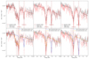 |
Fig. B.1. Zoom of the fit around the Kα lines for the three low-luminosity observations of GRS 195+105+105. The upper panels show the results of the autofit procedure with Gaussians, and the lower panels show the results of a fit with two photoionization zones; the lower ξ was fixed at zero velocity. The dashed lines show the energy of the main lines affecting the photoionization zones of each observation. |
Appendix C: Results of the line detection procedure for exposures analyzed in this work
C.1. Detections in all exposures
EW values for each line and each exposure analyzed in the sample. The sources are ordered alphabetically and with observations listed chronologically. The columns also report the exposure time after data reduction and either EW results for detections or EW upper limits for non-detections of the main lines. Line EWs are only provided for detections above 3 σ significance (see Sect. 3.4) along with 90% uncertainties. Upper limits above 100 eV are not reported. The ObsIDs marked with a dagger symbol (†) have pile-up values between 5 and 7% after the data reduction process.
C.2. Parameters of Kα detections
Main characteristics of significant Kα line detections from the sample. Uncertainties regarding luminosity are not quoted, as they were negligible.
All Tables
Details of accretion states with reports of absorption line detection in both our work and the literature.
EW values for each line and each exposure analyzed in the sample. The sources are ordered alphabetically and with observations listed chronologically. The columns also report the exposure time after data reduction and either EW results for detections or EW upper limits for non-detections of the main lines. Line EWs are only provided for detections above 3 σ significance (see Sect. 3.4) along with 90% uncertainties. Upper limits above 100 eV are not reported. The ObsIDs marked with a dagger symbol (†) have pile-up values between 5 and 7% after the data reduction process.
Main characteristics of significant Kα line detections from the sample. Uncertainties regarding luminosity are not quoted, as they were negligible.
All Figures
|
Fig. 1. Steps of the line detection procedure for a standard 4U130-47 Chandra spectra. Panel A: spectrum in the 4–10 keV band after the first continuum fit in this band. Panel B: map of the line blind search restricted to positive regions ΔC (i.e., improvements of the fit). Standard confidence intervals are highlighted with different line styles, and the color map shows the ΔC improvements of emission and absorption lines. Panel C: ratio plot of the best fit model once absorption lines are added. Panel D: remaining residuals seen through a second blind search. |
| In the text | |
|
Fig. 2. Hardness intensity diagram with the position of all line detections in the sample. The sample is split according to the viewing angle: the left panel is restricted to dippers, or sources, with i > 55°, while the right panel shows all other sources. The vertical and horizontal lines highlight the luminosity and HR thresholds proposed in Sect. 4.2. |
| In the text | |
|
Fig. 3. Distribution of intrinsic line parameters (detections of each line, EW, blueshift, widths, and Kα EW ratio) for the entire sample. The parameters are split by source and instrument whenever relevant. The blueshift distributions are restricted to the Kα complex. |
| In the text | |
|
Fig. 4. Scatter plot of the Fe XXV Kα (left) and Fe XXVI Kα (right) velocity shifts against luminosity in Chandra observations. The scatter plot is color coded according to the sources. The gray dotted line corresponds to zero velocity and the brown line to the mean of the curated Kα blueshift distribution, whose standard deviation is visualized by the brown region. The biased Fe XXV Kα blueshifts measured in the obscured GRS 1915+105 observations, which are excluded from this distribution, are marked in dashes. |
| In the text | |
|
Fig. 5. Scatter plot of the EW and width for the Fe XXV Kα (left) and Fe XXVI Kα (right) lines in Chandra observations. The curves highlight the theoretical evolution of these parameters for a range of ionic column densities of the respective ions. |
| In the text | |
|
Fig. 6. Scatter plot of the Fe XXV Kα (left) and Fe XXVI Kα (right) EW against luminosity for the entire sample. The scatter plot is color coded according to the sources. |
| In the text | |
|
Fig. 7. Scatter plot of the Fe XXVI Kα/Fe XXV Kα EW ratio against luminosity for the entire sample. |
| In the text | |
|
Fig. 8. Hardness intensity diagram with the position of all detections in the sample and Fe XXVI Kα upper limits when no line was detected. The diagram uses the same inclination split as in Fig. 2. The vertical and horizontal lines highlight the luminosity and HR thresholds proposed in Sect. 4.2. Sources with no inclination measurements in the right panel are shown with dashed markers. |
| In the text | |
|
Fig. 9. Hardness intensity diagrams of subsamples with relevant non-detections. Left panel: zoom on sources with detection and Fe XXVI Kα upper limits when no line was detected. Right panel: sources with constraining upper limits in the favorable zone (discussed in Sect. 4.3). |
| In the text | |
|
Fig. B.1. Zoom of the fit around the Kα lines for the three low-luminosity observations of GRS 195+105+105. The upper panels show the results of the autofit procedure with Gaussians, and the lower panels show the results of a fit with two photoionization zones; the lower ξ was fixed at zero velocity. The dashed lines show the energy of the main lines affecting the photoionization zones of each observation. |
| In the text | |
Current usage metrics show cumulative count of Article Views (full-text article views including HTML views, PDF and ePub downloads, according to the available data) and Abstracts Views on Vision4Press platform.
Data correspond to usage on the plateform after 2015. The current usage metrics is available 48-96 hours after online publication and is updated daily on week days.
Initial download of the metrics may take a while.