| Issue |
A&A
Volume 652, August 2021
|
|
|---|---|---|
| Article Number | A107 | |
| Number of page(s) | 9 | |
| Section | Numerical methods and codes | |
| DOI | https://doi.org/10.1051/0004-6361/202141068 | |
| Published online | 19 August 2021 | |
Finding flares in Kepler and TESS data with recurrent deep neural networks
1
Konkoly Observatory, Research Centre for Astronomy and Earth Sciences, Eötvös Loránd Research Network (ELKH), Konkoly Thege Miklós út 15-17, 1121 Budapest, Hungary
e-mail: vidakris@konkoly.hu
2
Eötvös Loránd University, Pázmány Péter sétány 1/A, Budapest, Hungary
3
MTA CSFK Lendület Near-Field Cosmology Research Group, Budapest, Hungary
Received:
13
April
2021
Accepted:
24
May
2021
Stellar flares are an important aspect of magnetic activity – from both stellar evolution and circumstellar habitability viewpoints – but automatically and accurately finding them is still a challenge to researchers in the big data era of astronomy. We present an experiment to detect flares in space-borne photometric data using deep neural networks. Using a set of artificial data and real photometric data we trained a set of neural networks, and found that the best performing architectures were the recurrent neural networks using long short-term memory layers. The best trained network detected flares over 5σ with ≳80% recall and precision and was also capable of distinguishing typical false signals (e.g., maxima of RR Lyr stars) from real flares. Testing the network –trained on Kepler data– on TESS light curves showed that the neural net is able to generalize and find flares –with similar effectiveness– in completely new data with different sampling and characteristics from those of the training set ő.
Key words: methods: data analysis / stars: activity / stars: flare / stars: late-type
© ESO 2021
1. Introduction
Stellar flares are the result of magnetic field line reconnection; they appear as sudden brightenings of the stellar atmosphere as a portion of magnetic energy is released. Flares are most common in late-type M-dwarfs (Walkowicz et al. 2011), but they appear in a wide range of main sequence stars, and even in some evolved giant stars (Oláh et al. 2021). Beyond a stellar astronomy viewpoint, these eruptions are interesting as they can influence their surroundings, and have serious effects on the atmosphere evolution of their orbiting planets (Khodachenko et al. 2007; Yelle et al. 2008; Vida et al. 2017).
Recent and upcoming photometric space missions, such as Kepler (Borucki et al. 2010), TESS (Ricker et al. 2015), and PLATO (Rauer et al. 2014), provide an unprecedented opportunity for astronomers to study these events. But this opportunity comes with a new challenge: while earlier observations of a single object could be handled relatively easily by manual analysis, investigating photometric data of hundreds or even thousands of targets manually is not feasible.
There are several existing approaches to detecting these transient events in space automatically. These are often based on smoothing the light curve, and detecting the outliers by some criteria (Davenport 2016; Stelzer et al. 2016) or using an alternative method (e.g., the RANSAC method, see Vida & Roettenbacher 2018). A known issue with these methods is that they are prone to misidentifying other astrophysical phenomena such as flares (e.g., maxima of KIC 1572802, an RR Lyræ star), and they also require input from the user. These issues can be possibly remedied by deep learning methods; a neural network, once trained with appropriate training data, does not need any user input or parametrization, and can operate autonomously on new data. Also, in some cases, the “astrophysical noise” (as in RR Lyr peaks marked as flares) can be filtered out. While the training of such networks is time consuming –a single iteration can have a runtime of several hours even on recent GPUs– analysis of new data is relatively fast: for example, face recognition can be done on the fly in video streams on mobile phones.
Using simple dense neural networks would be impractical for this case, because this approach would yield too many variables, making the algorithm too slow. For time-series data, convolutional neural networks (CNNs, LeCun et al. 1999) are a much better choice, as these are much faster and can be better adapted to such data. Convolutional networks take advantage of the hierarchical pattern in data and assemble more complex patterns using smaller and simpler patterns. Recently, Feinstein et al. (2020) presented a method to find flares using CNNs.
Another approach is using recurrent neural networks (RNNs): here, connections between nodes form a directed graph along a temporal sequence. This allows them to “remember” their previous state, making them suitable for a wide range of problems, from improved machine translation (Sutskever et al. 2014) to anomaly detection in ECG time signals (Oh et al. 2018). This can give them the power to not simply detect outlying points, but also to compare the analyzed data to previously seen light-curve parts, just as a human would do, making it a powerful tool for scientists.
In the present paper, we present the first results of our flare-detection method based on RNNs. In Sect. 2 we show the data preparation steps, in Sect. 3 the design, and in Sect. 4 the evaluation of tested networks. In Sects. 5 and 6 we present the validation steps, while in Sect. 7 we discuss the performance of our network. We dedicate Sect. 8 to presenting our dead ends and finally, we summarize our results in Sect. 10.
2. Input data
Our training data consist of two sets: artificial data and real Kepler observations. For the artificial data we generated light curves of spotted stars using PyMacula (Kipping 2012)1. The artificial light curves were generated with different rotation periods. The periods of the light curves were chosen from a lognormal distribution with a mean of log5 days, and the lowest period was set to 0.4 days. This distribution was selected to represent the most active fast-rotating stars, which are more likely to show flares. To these light curves a randomly selected number of spots (between 2–12) was added with spot evolution enabled. We then added noise with a normal distribution with a noise level of 8 × 10⁻³ − 4 × 10⁻⁵ (in normalized flux units), which corresponds to typical short-cadence noise levels for 7–16 magnitude stars2. These light curves were injected with flares using the analytical flare model of Davenport (2016) using FWHM values of between 0.5 and 1 hr with uniform distribution and amplitudes with lognormal distribution with a mean of 10−5 and a standard deviation of 1. The number of injected flares per star varied between 5 and 200. The code ocelot-gym used to create spotted light curves injected with flares for the training is available on GitHub3.
Real Kepler observations with flares were selected from the targets of Roettenbacher & Vida (2018) with additional targets as ‘astrophysical noise’ (RR Lyr, Cepheids, flaring, and non-flaring eclipsing binaries, systems with exoplanets, and irregular variable stars). The selected short-cadence light curves were first flagged with the FLATW’RM code (Vida & Roettenbacher 2018), and these flagged data were checked twice manually and re-flagged if needed. This set consisted of 214 light curves, which were separated into an ‘active’ (107) and a ‘quiet’ (207) set for the first steps of the model selection. For the training, we used only short-cadence data, because interpolating the long-cadence light curves would add too much information.
We found that using both time and intensity data as input, the candidate neural nets did not converge, and therefore we interpolated our data to one-minute cadence, and used only the flux values as a one-dimensional input vector. This, on one hand, helps some issues with the time axis (e.g., normalization), and also makes the analysis faster. On the other hand, this limits the usage of the trained network: while data with five-minute cadence might still be handled well, interpolating a long-cadence observation with 30-minute sampling adds too much information to the data, and also renders the analysis unnecessarily slow. Different training is therefore needed for data of this kind. Gaps in the data were interpolated and filled with random noise with a normal distribution – and with characteristics of the light curve– to avoid jumps in the light curve that can mimic flares.
Flux data were also standardized after dropping NaN non-numeric values. The observed flux was first divided by its truncated mean, and was then centered around zero by subtracting 1. Finally, we divided by the truncated peak-to-peak variation. The truncated mean and peak-to-peak variation were calculated after dropping flux values above the 99.9th percentile of the data (leaving out large flares). Experience shows that machine learning algorithms perform best with standardized data with variation of approximately 1.
The prepared light curves were concatenated and used as a single one-dimensional input vector for the training. Training can be made faster by training multiple batches simultaneously (the batch number is mainly limited by GPU memory). However, creating batches with time-series is not obvious, as the consecutive data parts are not independent from each other. Therefore, as opposed to the default time-series generator in Keras, we created the batches by separating the data into b consecutive data segments, and fed these batches one after the other into the network for training. Using too large a number of batches might hinder the convergence of the network (especially if the length of the resulting batches is of approximately the same magnitude as the events we are looking for), but we found a batch number of b = 2048 to be a good compromise. With this setup, the runtime of a single epoch was 12–17 min on an NVidia GeForce RTX 2080 Ti graphics card.
For the analysis, each light-curve point was associated with a flag to mark whether or not it is part of a flare. This flag was determined based on 64-point windows starting from the given data point: the labels were calculated as the average of the input flags rounded to 0 or 1. In the case of the final data points, where the number of the remaining points is less than 64, the original data points were mirrored in order to avoid losing any data. Our experiments with different window sizes and different ways of calculating the labels, for example including exceptions for short events, or aligning the windows differently, all yielded poorer results (see also Sect. 8).
After selecting the most successful network candidate we returned to the input: we used its output to re-examine the training data. We checked the output for possible missed events not marked as flares in the original set, or light-curve regions marked incorrectly as flares. The network was then re-trained with this refined training set. These corrections improved the performance (recall or accuracy) by up to 10% in the case of smaller events.
3. Network architecture
The neural network was built using Keras4, a deep-learning API built on Tensorflow5. We experimented with a large number of network architectures (see Sect. 8), but our final network candidates consisted of sequential models with two or three GRU/long short-term memory (LSTM) layers with 128/256 units (Gated Recurrent Unit, Cho et al. 2014; Long Short-Term Memory layer, Hochreiter & Schmidhuber 1997). Between the recurrent layers a dropout layer (Srivastava et al. 2014) was added with a dropout rate of 0.2. Utilizing such layers in a network serves as a kind of regularization, by temporarily removing a fraction of the neurons from the network at random. This way, our model can achieve lower generalization error, thus prevent overfitting, at the cost of somewhat increased computation time. After the recurrent layers, a single one-unit dense layer was added with sigmoid activation to generate the final output (Fig. 1). The networks were optimized using a binary cross-entropy loss function and an NAdam optimizer (Kingma & Ba 2014; Dozat 2015). As the ratio of flaring and nonflaring data points is far from equal, weighting is important during the fit, and so the model pays more attention to samples from the under-represented class. We weighted the flaring points with their ratio to the total number of points.
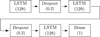 |
Fig. 1. Final neural network architecture consisting of three LSTM layers with 128 units each, and a dropout layer between them with dropout rate of 0.2. The output was generated by a one-unit dense layer with a sigmoid activation function. |
The first stage of the model selection was performed using the HParams tool of Keras, which allowed us to compare a variety of model architectures. The options tested in this step of the hyperparameter tuning are summarized in Table 1 (see also Appendix A for more details). At this stage we trained the networks on our artificial data and the flaring Kepler data set. From the best performing models, the first five best-performing networks were selected during hyperparameter tuning. We then added the non-flaring ‘astrophysical noise’ observations (see Fig. 2) to the training sample to find a network that can not only detect flares, but also neglect irrelevant signals. While with the flaring data the GRU networks performed well, adding the nonflaring data produced a large number of false positive detections.
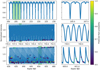 |
Fig. 2. Examples from the set used as ‘astrophysical noise’. Larger points indicate points predicted as possible flares by the trained network. From top to bottom: algol type-, β Lyrae type eclipsing binary, and RR Lyrae. The few-point false negative detections make post-processing and validation a necessary but relatively easy task. The false positive detections in the plots are cleaned by median filtering before the validation step. |
Parameters of the tested network architectures.
4. Evaluation
After training the candidate networks, we ran a prediction for the validation data set, and compared them based on their accuracy (the rate of correctly classified points), classification error rate (rate of incorrectly classified points), recall (ratio of recovered flare points), precision (ratio of correct detection in the selected points), false positive rate, and Fβ values:
Here, TP, FN, and FP stand for true positives, false negatives, and false positives, respectively, and β = 1. The Fβ score gives the weighted harmonic mean of precision and recall. We find that the best-performing networks are the two-layered LSTM(256) with or without additional CNN layers, and the three-layered LSTM(128) networks. We selected the latter candidate as the final choice, as its runtime was ≈20−40% lower (see Appendix A).
Evaluating the performance of RNNs is not as straightforward as in the case of binary classifiers for example, where we usually have a set of training and test data with an input label for each item, which can be easily compared to the output label with the highest probability (for the complexity of the task see for example Arras et al. 2019). Particularly, in the case of the flare detection using temporal information, the problem comes from the lack of solid ground truth. First, we have to decide which kind of phenomenon is considered to be a flare and have to decide which points are part of that flare-like event and which are not. As a possible solution, we split the light curves and fit each input and predicted segment with a model individually and use the fits as ‘labels’. The fitting procedure is described in Sect. 6. In the following, we bin the flares by their signal-to-noise ratio and relative amplitude, calculate the aforementioned metrics for each bin, and compare the resulting curves instead of single numbers. As it is nearly impossible to force the RNN to select the same points for a given flare that we flagged as input, the fitting may result in a different number of flares within the same event if its structure is complex. Therefore, we consider input-output flares the same if they lie within 0.02 days.
5. K-Fold cross-validation
To check the robustness of the neural network, we performed K-Fold cross-validation on the training data. This method is commonly used in applied machine learning to compare models and to see how dependent the trained network is on the particular set of training data. The K-Fold cross-validation method is based on separating a set of test data (we used 10% of the total data), and shuffled the remaining data into nonoverlapping training and validation sets multiple times (we used five runs). The network is then trained on each shuffled set, yielding five slightly different trained networks with different starting weights and different training data. The result of this test is shown in Fig. 7: above 3−5σ signal level the difference between the five models is only a few percent in both the precision and recall metrics, suggesting a robust model.
6. Post-processing and validation
The raw output of the network sometimes contained single false-positive points and also smaller sections of flares that were not marked (false negatives), as seen for example in Fig. 3. These issues can be solved by smoothing the raw output by a median filter. However, the size of the filter should be chosen carefully: too short a kernel size might not be efficient enough, while an overly large kernel can filter out shorter events. Figure 4 shows the test showing the effect of different kernel size on the precision/recall metrics. A window size of 47 and 63 points yielded the best results with a cutoff of 0.2. For the Kepler data, we chose a 47 point-wide kernel, as it gave somewhat steadier output, while for the injected flares we used a 63 point filter after averaging the predictions of different K-Fold weights with a cutoff of 0.3 (see Sect. 7). When selecting the filtering method before validation, we favored those options that yielded somewhat higher recall at the cost of losing some precision. Picking a kernel that filters out smaller events among false positives would give higher precision values, but these can be selected later at the validation phase.
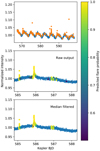 |
Fig. 3. Example output from the validation data set (KIC 012156549). The top panel shows the input light curve (blue points) with all the data points marked by the neural network as flares (orange points). The middle panel is zoomed in, with the color code showing the raw output from the predictions where the output probability is higher than 0.5. There are a few points within flares that are not marked (false negatives), and some single points that are incorrectly identified as flares (false positives). This can be rectified by smoothing the output probabilities by a median filter (bottom plot panel). |
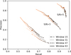 |
Fig. 4. Precision–recall curve with median filters of different kernel sizes. The three batches show all flare events from the test data (left), and cases with flares in which the highest point compared to the noise in the light curve is above 3σ (middle) and 5σ (right). The color coding shows different cutoff levels above which a flux measurement is considered to be a flare. The darker the color the higher the cutoff threshold. The point marks the location of a cutoff value of 0.2 for the 47-point-width median filtered case. See text for details. |
The network managed to find the flare events correctly, but in several cases it seemed to neglect part of the eruption. To correct these issues, and to filter out possible remaining false positive detections, we decided to add a further post-processing step to mark these missing points, to detect possible false positives, and also to have an output that is more useful for physical analysis.
For each marked section, we took a part of the light curve with a length equal to three times the duration of the originally marked points and centered on the middle of the selected window (see e.g., Fig. 5.). We fitted these points iteratively with a second-order polynomial, filtering points out above 0.5σ, then subtracted this trend. The residual is used to locate the flare event in the window. To eliminate outliers which can mislead the algorithm, we used a median filter with a width of three points. After this, the original light curve was fitted again with a combination of a second-order polynomial and the analytic flare model of Davenport (2016). If the timescale of the light curve variability is comparable to the length of the selected window, the second-order polynomial may not fit the background properly, and a higher order is needed. To overcome this issue, we repeated the fitting procedure using a third-order polynomial and calculated the Bayesian information criterion (BIC; Liddle 2007) for both in order to select the better model. The BIC is defined as
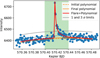 |
Fig. 5. Example for the validation. The green area shows the section marked as a probable flare. Additional flare-length windows before and after the marked region are selected, and fitted by a low-order polynomial. The fit is subtracted from the light curve, and the residual is fitted by another low-order polynomial and an analytical flare model. If the peak of the fit is above the 3σ noise level, the event is marked as validated. |
where n is the number of points, k is the degree of freedom, and y and  are the measured and modeled flux values, respectively. The better the model, the lower the BIC. The final model was removed from the light curve and the residual σ was used as the noise level to calculate the signal-to-noise ratio (S/N). If there was still at least three consecutive points above the noise level at 1.5σ, an additional fit was performed for complex events. This step was repeated until the highest point went down the noise level.
From the marked events, only those that have their peak at more than 5σ above the noise level can be considered as real flares with high probability. Below this, the rate of false positive events increases rapidly (see Sect. 7). The output also includes the beginning and end time of the events (those points where the fitted model reaches 1σ level) and the equivalent duration of the flares (their integrated intensity over the event duration). Following the work of Kővári et al. (2007), the latter can be used to estimate the flare energy from the quiescent flux of the star, assuming a simple black-body model, which requires knowledge of stellar effective temperate and radius. We collected these parameters from the Kepler Input Catalog (Brown et al. 2011) and calculated the flare frequency distributions (FFDs) for some example stars that are shown in Fig. 6. The energy distribution characteristics of the recovered flare energies is similar to that seen in other methods, but a large number of low-energy events are recovered, which will be helpful in order to obtain information on a wide energy range.
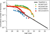 |
Fig. 6. Four example flare frequency distributions of KIC 4671547, KIC 3540728, KIC 1570934 and KIC 12102573 (colored symbols). As a comparison we adopted and plotted the fit of FFD of the well-known star TRAPPIST-1 (black line) from Vida et al. (2017). |
7. Performance
We tested the performance of the network on two data sets: a set of Kepler light curves that were not used for training and validation steps, and light curves with injected flares. Both methods have their drawbacks: with real light curves we can compare the network performance to a human performing the same task, but we do not know the ground truth, that is, where the flares occurred in reality, and also it is much harder to obtain manually flagged data compared to generating light curves. Artificial light curves are easy to generate, and we know precisely where the flares are, but their characteristics might be somewhat different from those of real events.
To generate the flare-injected data, we selected ten stars from our sample, and removed the flares by smoothing, using multiple passes of a median filter. We then injected ten flares into each data set with peaks ranging between 2 and 15 times the noise level. Those points that were above the noise level of the light curve were marked as part of the event. These steps were repeated 100 times for each star, yielding 10 000 flares in ≈30 000 days of data.
The performance of the network for the Kepler data set is shown in Fig. 7, where we plotted the precision and recall metrics as a function of the S/N (left panel) and the measured relative amplitude of flares (right panel). The test shows that above 5σ signal level, the LSTM was able to recover ≳80% of the manually marked flares with a precision of ≳70%. The shape of the metric curves is different in the right plot. The low precision is caused by the very low number of events: there were only a few dozen events above 10−2 relative amplitude.
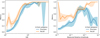 |
Fig. 7. K-fold cross-validation on the independent test data set. The curves show the precision (blue) and recall (orange) as a function of flare S/N (left) and relative amplitude (right). The raw predictions were median filtered with a window length of 47. Points above a probability of 0.2 are considered to be flares. Above the 3−5σ signal level, the uncertainty of the models as a result of different training sets is reduced to a few percent, suggesting that the trained model is robust, and that the training sets are sufficiently large. We note the logarithmic abscissa. The low precision in the right plot is caused by the very low number of events. |
For the injected data set, we first tried prediction with the K-Fold weights. We found that, in contrast with the Kepler data set, using only a single K-Fold weight lead to significantly poorer performance. Therefore, we calculated the weighted average of the predictions yielded by different K-Fold weights, which improved the results considerably. In this case, if one of the networks predicted a point to be a flare with a probability of > 0.98, we kept it as a flare event regardless of the results of the other networks. The results of this test are shown in Fig. 8. The typical runtime for one light curve with a length of one-quarter was ≈25 s on a GPU with a batch number of b = 16.
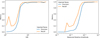 |
Fig. 8. Injection-recovery test using the best-performing network, combining the weights of all the K-Fold results. The combined raw predictions were post-processed in the same way as in the case shown in Fig. 7. We note the logarithmic abscissa. |
As seen in Fig. 8, the LSTM performs better at finding light curves in less noisy areas than finding large-amplitude flares in the noise. The non-zero recall number in the case of the lowest S/N values is introduced by the flare-fitting algorithm. First, it tries to find and fit the significant outlier points in a given flare region regardless of their origin; second, some information sometimes remains in the residual of a non-perfect fit –which is caused by the difference between the shape of the model and the observed flare– that is considered to be a flare. Moreover, the number of flagged points within a flare is usually different in the manually and automatically labeled data sets, that is, the duration of the flares is different, which provides the opportunity to find different numbers of flare-like events within a region of a given flare.
We also tested the network on TESS data, in a similar way to Feinstein et al. (2020). Light curves were downloaded from MAST using the Lightkurve tool6 (Lightkurve Collaboration 2018). Labels for flares were obtained from Günther et al. (2020). This set contains a large number of flaring light curves, but the labels are not perfect: there is a number of missing flares, or incorrect labels, and these events bias our comparison, yielding incorrectly false positive or false negative detections. As the RNN requires equidistant sampling, the light curves were resampled at a two-minute cadence, which is equal to the TESS short-cadence sampling.
We predicted flares using all the weights saved during the Kepler K-fold test, and additionally we trained the network with all available Kepler light curves and utilized those weights as well. In the individual tests, we were not able to recover as many flares as in the case of the Kepler data. As it turned out, the main problem was the normalization of light curves. If we transform the flux values to the range of 0–1, the large-amplitude flares suppress the small events, making those impossible to identify. To overcome this problem, we sigma clipped the large flares before normalization. However this step raised another issue: the height of high-amplitude flares rose well above unity, which made the RNN uncertain, yielding much lower probabilities for these previously well-recovered events. Thus, we somehow had to combine the results of different predictions. After an extensive test, we found that the best solution is to use three weights rather than only one, predict the location of flares in light curves normalized by both methods, and calculate the weighted average of their predictions. The weights are unity, unless a given instance predicts an event with a probability of greater than 0.9, in which case its prediction takes over the others. This way, both small and large events are captured, and the false negative ratio is minimized.
The precision and recall values as a function of signal-to-noise ratio and relative flare amplitude are shown in Fig. 9. After a precision–recall test similar to the one presented in Fig. 4, the raw predictions were median filtered with a window length of 32 and points above a probability threshold of 0.5 were considered to be flares. Although the TESS data have different sampling and noise characteristics that may influence the results, our test showed that we are able to recover a similar number of flares as in the Kepler data shown in Figs. 7 and 8. The shapes of the precision curves are similar too, but the absolute vales are 10–40% lower for TESS data than for Kepler data. Plotting the individual events marked as flares by our network, we found on the order of 4000-5000 flares to be missing from the original catalog with similar characteristics to those plotted in Fig. 10. Considering the number of flares in the catalog of Günther et al. (2020), which is about 8600, this difference is understandable. This test shows that even the current network is able to generalize and find flares –with similar effectiveness– in completely new data with previously unseen sampling and characteristics.
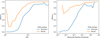 |
Fig. 9. Predicting flares in the TESS sample of Günther et al. (2020). These results were obtained using the combined weights of different training runs on the Kepler sample. The raw predictions were median filtered with a window length of 31. Points above a probability of 0.5 are considered to be flares. We note the logarithmic abscissa. |
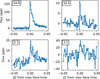 |
Fig. 10. Example high-S/N false-positive flares found by our LSTM algorithm in the TESS sample of Günther et al. (2020). The numbers in the upper left corners show the S/N. Less significant detections are dominated by nonflare events, i.e., genuine false positives. |
The flatwrm2 code and the network used by Feinstein et al. (2020) use different data sets and approaches. The latter is trained on TESS data that have different characteristics, and contain a larger flare sample compared to the Kepler sample. Another important difference lies in the scaling and normalization of the input data: while we normalize the light curve as a whole, in the case of stella, each window is normalized separately. Therefore, flatwrm2 might perform worse in cases where the light curve itself is peculiar, and the normalization process yields data with events that are either too large or too small to be recognized by the neural net. On the other hand, flatwrm2 could outperform stella in the case of atypical flare shapes, complex flares, or long flares, because the network remembers its previous states thanks to the forget and update gates in LSTM. While flatwrm2 was trained on Kepler short-cadence data only (and artificial light curves based on Kepler data), the LSTM network could be better in generalization. However, a qualitative comparison of the two methods is currently not possible given their mission-oriented training sets.
8. Failures
Research is rarely a linear process of forming the idea, working through it, and analyzing the results. This is especially true for developing machine learning methods. In this section, we briefly summarize some of our experiments that did not work at all or gave inferior results.
Initially, we tried to select the best candidates based on simple model data only, and used these weights on real data. However, we found that over-simplified light curve models yield unusable model weights and architectures.
As mentioned in Sect. 2, standardizing input data is crucial. Here, simply dividing by the mean or median of each data set did not work, and also normalizing the data with their standard deviation proved problematic: in some cases larger flares were scaled up, and were neglected by the network.
We experimented with a large number of network architectures that did not converge at all, or did not yield the expected results. We tried: (i) simple dense networks with different sizes; (ii) convolutional networks; (iii) hybrid networks utilizing both recurrent nets and dense or convolutional networks in parallel, with various inferior results (our takeaway lesson was that a more complex network does not necessarily perform better). Adding an extra dense layer with 32 units after the selected recurrent layers also did not improve the results. Bidirectional recurrent networks (that analyze the input data in both directions) worked in some cases slightly better, but at the cost of doubling the runtime. Therefore, we decided to use a one-directional analysis (with this the prediction time for a single-quarter Kepler light curve is ≈13 seconds on a GPU with a batch number of b = 64).
Changing the window size for training did not improve the results either. Using a shorter window, the number of false-positive detections increased significantly, while larger windows tended to smear out smaller events.
9. Code availability
To make our RNN a useful tool for finding flares in the era of big data, we prepared a user-friendly code, that we call flatwrm2, which is available through a GitHub repository7, and can be installed via PyPI. Passing a flux time-series, flatwrm2 prepares the light curve, and predicts and validates the possible flare events. The user obtains a number of output parameters, such as the location, FWHM, relative amplitude, and signal-to-noise ratio of flares, of which the latter can be used to select the most likely intrinsic events. Besides the raw code, we have written a tutorial Notebook which guides the user through the prediction and validation steps.
10. Summary
We present an experiment to detect flares in space-borne photometric data using deep neural networks. After testing a large number of network architectures, we conclude that the best-performing network is a RNN based on using LSTM layers. After training a network using a set of artificial light curves and real short-cadence Kepler observations of flaring and nonflaring stars, the network is not only able to detect flares with peaks over 5σ with 80–90% recall and precision, but is also capable of distinguishing false signals that typically confuse flare-finding algorithms (e.g., maxima of RR Lyr stars) from real flares.
In the future, we plan to analyze a large amount of Kepler and TESS data in order to gain a better understanding of flaring stars. The code and the weight files are available in the public domain for the scientific community.
Acknowledgments
The authors would like to thank deeplearning.ai and Coursera for hosting their online course on different aspects on machine learning, without which this work would never be possible. We thank the referee for their swift replies and the valuable remarks that considerably helped us to improved the manuscript and the code availability. BS was supported by the ÚNKP-19-3 New National Excellence Program of the Ministry for Innovation and Technology. This project has been supported by the Lendület Program of the Hungarian Academy of Sciences, project No. LP2018-7/2020, the NKFI KH-130526, NKFI K-131508 and 2019-2.1.11-TÉT-2019-00056 grants. On behalf of “Analysis of space-borne photometric data” project we thank for the usage of ELKH Cloud (https://science-cloud.hu) that helped us achieving the results published in this paper. Authors acknowledge the financial support of the Austrian-Hungarian Action Foundation (95 öu3, 98öu5, 101öu13). The authors would like to acknowledge the following softwares and software packages: Python (Van Rossum & Drake 2009); Numpy (van der Walt et al. 2011); Pandas (McKinney et al. 2010); Scikit-learn (Pedregosa et al. 2011); Tensorflow (Abadi et al. 2015); Keras (Chollet et al. 2018); Matplotlib (Hunter 2007); scipy (Virtanen et al. 2020); PyMacula (Kipping 2012); Lightkurve (Lightkurve Collaboration 2018).
References
- Abadi, M., Agarwal, A., Barham, P., et al. 2015, TensorFlow: Large-Scale Machine Learning on Heterogeneous Systems, software available from tensorflow.org [Google Scholar]
- Arras, L., Osman, A., Müller, K. R., & Samek, W. 2019, ArXiv e-prints [arXiv:1904.11829] [Google Scholar]
- Borucki, W. J., Koch, D., Basri, G., et al. 2010, Science, 327, 977 [NASA ADS] [CrossRef] [PubMed] [Google Scholar]
- Brown, T. M., Latham, D. W., Everett, M. E., & Esquerdo, G. A. 2011, AJ, 142, 112 [NASA ADS] [CrossRef] [Google Scholar]
- Cho, K., Van Merriënboer, B., Gulcehre, C., et al. 2014, ArXiv e-prints [arXiv:1406.1078] [Google Scholar]
- Chollet, F., et al. 2018, Keras: The Python Deep Learning library, https://keras.io [Google Scholar]
- Davenport, J. R. A. 2016, ApJ, 829, 23 [Google Scholar]
- Dozat, T. 2015, http://cs229.stanford.edu/proj2015/054_report.pdf [Google Scholar]
- Feinstein, A. D., Montet, B. T., Ansdell, M., et al. 2020, AJ, 160, 219 [CrossRef] [Google Scholar]
- Günther, M. N., Zhan, Z., Seager, S., et al. 2020, AJ, 159, 60 [CrossRef] [Google Scholar]
- Hochreiter, S., & Schmidhuber, J. 1997, Neural Comput., 9, 1735 [CrossRef] [PubMed] [Google Scholar]
- Hunter, J. D. 2007, Comput. Sci. Eng., 9, 90 [NASA ADS] [CrossRef] [Google Scholar]
- Khodachenko, M. L., Ribas, I., Lammer, H., et al. 2007, Astrobiology, 7, 167 [NASA ADS] [CrossRef] [PubMed] [Google Scholar]
- Kővári, Zs., Vilardell, F., Ribas, I., et al. 2007, Astron. Nachr., 328, 904 [NASA ADS] [CrossRef] [Google Scholar]
- Kingma, D. P., & Ba, J. 2014, ArXiv e-prints [arXiv:1412.6980] [Google Scholar]
- Kipping, D. M. 2012, macula: Rotational modulations in the photometry of spotted stars [Google Scholar]
- LeCun, Y., Haffner, P., Bottou, L., & Bengio, Y. 1999, in Feature Grouping, ed. D. Forsyth (Springer) [Google Scholar]
- Liddle, A. R. 2007, MNRAS, 377, L74 [NASA ADS] [Google Scholar]
- Lightkurve Collaboration (Cardoso, J. V. d. M., et al.) 2018, Lightkurve: Kepler and TESS time series analysis in Python (Astrophysics Source Code Library) [Google Scholar]
- McKinney, W. 2010, in Proceedings of the 9th Python in Science Conference, eds. S. van der Walt, & J. Millman, 51 [Google Scholar]
- Oh, S. L., Ng, E. Y., San Tan, R., & Acharya, U. R. 2018, Comput. Biol. Med., 102, 278 [CrossRef] [Google Scholar]
- Oláh, K., Kövári, Zs., Günther, M. N., et al. 2021, A&A, 647, A62 [CrossRef] [EDP Sciences] [Google Scholar]
- Pedregosa, F., Varoquaux, G., Gramfort, A., et al. 2011, J. Mach. Learn. Res., 12, 2825 [Google Scholar]
- Rauer, H., Catala, C., Aerts, C., et al. 2014, Exp. Astron., 38, 249 [Google Scholar]
- Ricker, G. R., Winn, J. N., Vanderspek, R., et al. 2015, J. Astron. Telesc. Instrum. Syst., 1, 014003 [Google Scholar]
- Roettenbacher, R. M., & Vida, K. 2018, ApJ, 868, 3 [NASA ADS] [CrossRef] [Google Scholar]
- Srivastava, N., Hinton, G., Krizhevsky, A., Sutskever, I., & Salakhutdinov, R. 2014, J. Mach. Llearn. Res., 15, 1929 [Google Scholar]
- Stelzer, B., Damasso, M., Scholz, A., & Matt, S. P. 2016, MNRAS, 463, 1844 [NASA ADS] [CrossRef] [Google Scholar]
- Sutskever, I., Vinyals, O., & Le, Q. V. 2014, ArXiv e-prints [arXiv:1409.3215] [Google Scholar]
- van der Walt, S., Colbert, S. C., & Varoquaux, G. 2011, Comput. Sci. Eng., 13, 22 [Google Scholar]
- Van Rossum, G., & Drake, F. L. 2009, Python 3 Reference Manual (Scotts Valley, CA: CreateSpace) [Google Scholar]
- Vida, K., & Roettenbacher, R. M. 2018, A&A, 616, A163 [NASA ADS] [CrossRef] [EDP Sciences] [Google Scholar]
- Vida, K., Kövári, Zs., Pál, A., Oláh, K., & Kriskovics, L. 2017, ApJ, 841, 124 [NASA ADS] [CrossRef] [Google Scholar]
- Virtanen, P., Gommers, R., Oliphant, T. E., et al. 2020, Nat. Methods, 17, 261 [Google Scholar]
- Walkowicz, L. M., Basri, G., Batalha, N., et al. 2011, AJ, 141, 50 [NASA ADS] [CrossRef] [Google Scholar]
- Yelle, R., Lammer, H., & Ip, W.-H. 2008, Space Sci. Rev., 139, 437 [NASA ADS] [CrossRef] [Google Scholar]
Appendix A: Performance of different architectures
Figure A.1 shows the performance of the RNN architectures that we designed, trained, and tested on the same data set. As a single metric is not enough to select the best one, we plotted the accuracy, recall, precision, Fβ, along with the training and evaluation time compared to the slowest instance, respectively. The TP, FP, and FN values were calculated from the time-points at which the detected flares were at maximum. The accuracy is biased as the number of TN flares, considering that all the points that are not flagged, is orders of magnitude larger than the number of flagged points. The rows in labels are the name, units, and layers of the kernels, and the dropout value and number of the trained dense layers after the RNN units. The last dense layer that is used to link the outputs is not shown. In the case of the second network, we used two CNN layers with filter sizes of 16 and 32 before the RNN. We selected the third architecture to work with, as it yielded almost the same results as the first two networks shown in the plot, but with a reduced training time of only 40% and 20%, respectively.
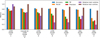 |
Fig. A.1. Performance of the designed and tested RNN architectures. The bars show the accuracy (blue), recall (orange), Fβ (green), precision (red), and relative run times of training (pink) and evaluating (brown) compared to the slowest instance, respectively. The networks where loss started to increase dramatically after some epoch were removed. |
All Tables
All Figures
|
Fig. 1. Final neural network architecture consisting of three LSTM layers with 128 units each, and a dropout layer between them with dropout rate of 0.2. The output was generated by a one-unit dense layer with a sigmoid activation function. |
| In the text | |
|
Fig. 2. Examples from the set used as ‘astrophysical noise’. Larger points indicate points predicted as possible flares by the trained network. From top to bottom: algol type-, β Lyrae type eclipsing binary, and RR Lyrae. The few-point false negative detections make post-processing and validation a necessary but relatively easy task. The false positive detections in the plots are cleaned by median filtering before the validation step. |
| In the text | |
|
Fig. 3. Example output from the validation data set (KIC 012156549). The top panel shows the input light curve (blue points) with all the data points marked by the neural network as flares (orange points). The middle panel is zoomed in, with the color code showing the raw output from the predictions where the output probability is higher than 0.5. There are a few points within flares that are not marked (false negatives), and some single points that are incorrectly identified as flares (false positives). This can be rectified by smoothing the output probabilities by a median filter (bottom plot panel). |
| In the text | |
|
Fig. 4. Precision–recall curve with median filters of different kernel sizes. The three batches show all flare events from the test data (left), and cases with flares in which the highest point compared to the noise in the light curve is above 3σ (middle) and 5σ (right). The color coding shows different cutoff levels above which a flux measurement is considered to be a flare. The darker the color the higher the cutoff threshold. The point marks the location of a cutoff value of 0.2 for the 47-point-width median filtered case. See text for details. |
| In the text | |
|
Fig. 5. Example for the validation. The green area shows the section marked as a probable flare. Additional flare-length windows before and after the marked region are selected, and fitted by a low-order polynomial. The fit is subtracted from the light curve, and the residual is fitted by another low-order polynomial and an analytical flare model. If the peak of the fit is above the 3σ noise level, the event is marked as validated. |
| In the text | |
|
Fig. 6. Four example flare frequency distributions of KIC 4671547, KIC 3540728, KIC 1570934 and KIC 12102573 (colored symbols). As a comparison we adopted and plotted the fit of FFD of the well-known star TRAPPIST-1 (black line) from Vida et al. (2017). |
| In the text | |
|
Fig. 7. K-fold cross-validation on the independent test data set. The curves show the precision (blue) and recall (orange) as a function of flare S/N (left) and relative amplitude (right). The raw predictions were median filtered with a window length of 47. Points above a probability of 0.2 are considered to be flares. Above the 3−5σ signal level, the uncertainty of the models as a result of different training sets is reduced to a few percent, suggesting that the trained model is robust, and that the training sets are sufficiently large. We note the logarithmic abscissa. The low precision in the right plot is caused by the very low number of events. |
| In the text | |
|
Fig. 8. Injection-recovery test using the best-performing network, combining the weights of all the K-Fold results. The combined raw predictions were post-processed in the same way as in the case shown in Fig. 7. We note the logarithmic abscissa. |
| In the text | |
|
Fig. 9. Predicting flares in the TESS sample of Günther et al. (2020). These results were obtained using the combined weights of different training runs on the Kepler sample. The raw predictions were median filtered with a window length of 31. Points above a probability of 0.5 are considered to be flares. We note the logarithmic abscissa. |
| In the text | |
|
Fig. 10. Example high-S/N false-positive flares found by our LSTM algorithm in the TESS sample of Günther et al. (2020). The numbers in the upper left corners show the S/N. Less significant detections are dominated by nonflare events, i.e., genuine false positives. |
| In the text | |
|
Fig. A.1. Performance of the designed and tested RNN architectures. The bars show the accuracy (blue), recall (orange), Fβ (green), precision (red), and relative run times of training (pink) and evaluating (brown) compared to the slowest instance, respectively. The networks where loss started to increase dramatically after some epoch were removed. |
| In the text | |
Current usage metrics show cumulative count of Article Views (full-text article views including HTML views, PDF and ePub downloads, according to the available data) and Abstracts Views on Vision4Press platform.
Data correspond to usage on the plateform after 2015. The current usage metrics is available 48-96 hours after online publication and is updated daily on week days.
Initial download of the metrics may take a while.