Fig. 5
Download original image
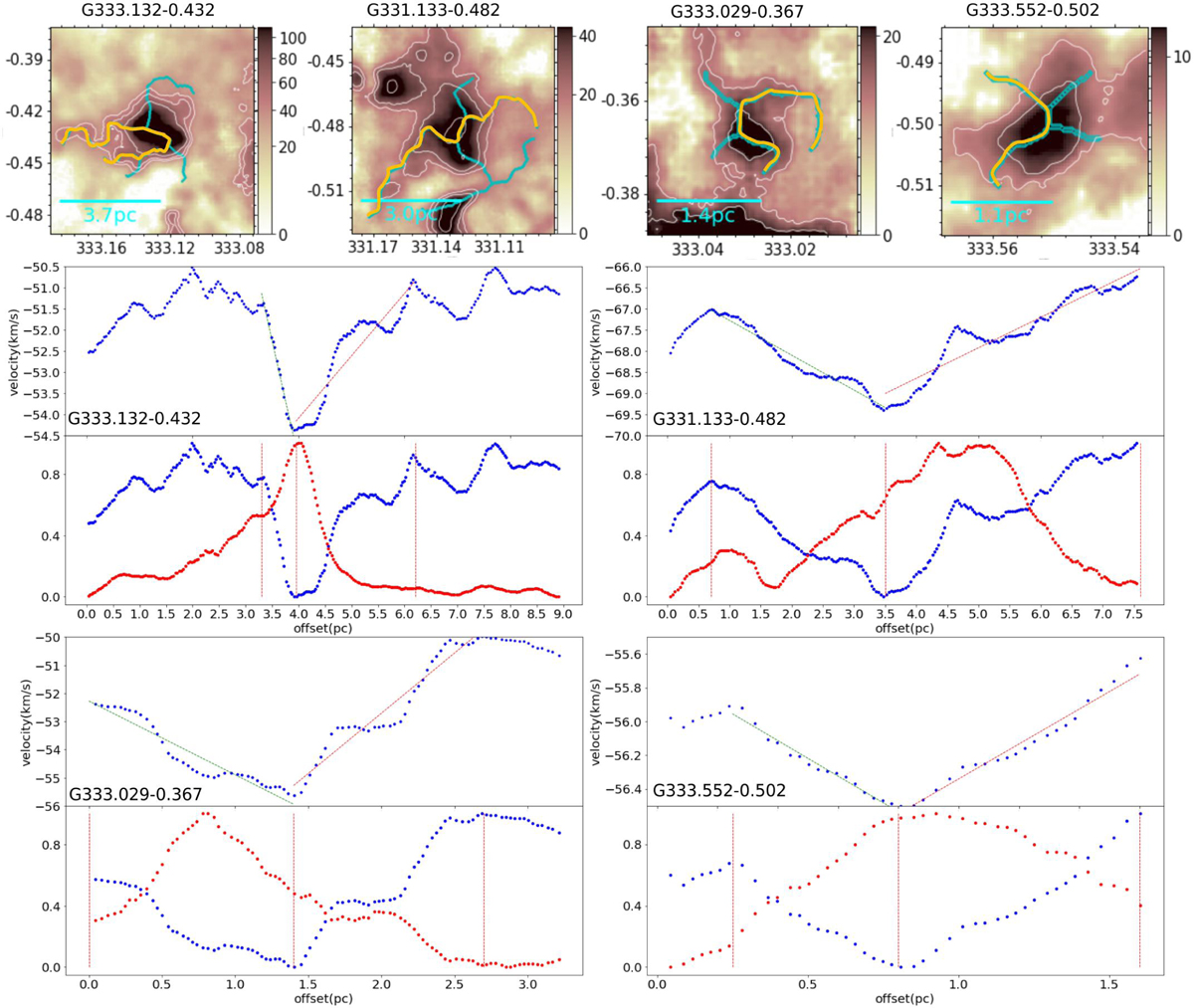
Four HFs structures used to demonstrate the velocity gradient fitting. The beamsize is ~0.34 pc. In the first row, the background is the integrated intensity map of 13CO (3-2); orange and cyan lines are the filaments identified by the filfinder algorithm. The background images were re-gridded, in contrast to those shown in Fig. 2. The two rows below show the velocity and intensity profiles extracted along the orange filaments. In panel a, velocity gradients are fitted in the ranges defined by the vertical dashed red lines in panel b. Straight lines show the linear fitting results. In panel b, dotted blue and red lines show the normalized velocity and intensity, respectively.
Current usage metrics show cumulative count of Article Views (full-text article views including HTML views, PDF and ePub downloads, according to the available data) and Abstracts Views on Vision4Press platform.
Data correspond to usage on the plateform after 2015. The current usage metrics is available 48-96 hours after online publication and is updated daily on week days.
Initial download of the metrics may take a while.