| Issue |
A&A
Volume 686, June 2024
|
|
|---|---|---|
| Article Number | A7 | |
| Number of page(s) | 19 | |
| Section | Astronomical instrumentation | |
| DOI | https://doi.org/10.1051/0004-6361/202348486 | |
| Published online | 24 May 2024 | |
Adaptive optics telemetry standard
Design and specification of a novel data exchange format
1
Faculdade de Engenharia da Universidade do Porto,
Rua Dr. Roberto Frias s/n,
4200-465
Porto,
Portugal
e-mail: This email address is being protected from spambots. You need JavaScript enabled to view it.
2
Center for Astrophysics and Gravitation, Instituto Superior Técnico,
Av. Rovisco Pais 1,
1049-001
Lisboa,
Portugal
3
Centre for Advanced Instrumentation, Durham University,
South Road,
Durham
DH1 3LE,
UK
4
European Southern Observatory,
Garching,
Germany
5
Université Paris-Saclay, Institut d’Optique Graduate School, CNRS,
Laboratoire Charles Fabry,
91127
Palaiseau,
France
6
Aix Marseille Univ, CNRS, CNES, LAM,
Marseille,
France
Received:
3
November
2023
Accepted:
8
February
2024
Abstract
Context. The amount of adaptive optics (AO) telemetry generated by visible/near-infrared ground-based observatories is ever greater, leading to a growing need for a standardised data exchange format to support performance analysis, AO research, and development activities that involve large-scale telemetry mining, processing, and curation.
Aims. This paper introduces the Adaptive Optics Telemetry (AOT) data exchange format as a standard for sharing AO telemetry from visible/infrared ground-based observatories. AOT is based on the flexible image transport system (FITS) and aims to provide unambiguous and consistent data access across various systems and configurations, including natural and single- or multiple-laser guide-star AO systems.
Methods. We designed AOT with a focus on two key use cases: atmospheric turbulence parameter estimation and point-spread function reconstruction. We prototyped and tested the design using existing AO telemetry datasets from multiple systems: single conjugate with natural and laser guide stars, tomographic systems with multi-channel wavefront sensors, and single- and multi-wavefront correctors in systems featuring either a Shack-Hartmann or Pyramid as the main wavefront sensor.
Results. The AOT file structure has been thoroughly defined, with specified data fields, descriptions, data types, units, and expected dimensions. To support this format, we have developed a Python package that enables the data conversion, reading, writing, and exploration of AOT files; it has been made publicly available and is compatible with a general-purpose Python package manager. We have demonstrated the flexibility of the AOT format by packaging data from five different instruments, installed on different telescopes.
Key words: atmospheric effects / instrumentation: adaptive optics / instrumentation: detectors / instrumentation: high angular resolution / instrumentation: miscellaneous / astronomical databases: miscellaneous
© The Authors 2024
 Open Access article, published by EDP Sciences, under the terms of the Creative Commons Attribution License (https://creativecommons.org/licenses/by/4.0), which permits unrestricted use, distribution, and reproduction in any medium, provided the original work is properly cited.
This article is published in open access under the Subscribe to Open model. This email address is being protected from spambots. You need JavaScript enabled to view it. to support open access publication.
1 Introduction
The adoption and interest in adaptive optics (AO) for astronomy has increased significantly in recent years. As a consequence, there has been a large increase in observatories and researchers producing AO telemetry data. We use the term ‘telemetry’ to represent AO internal signals such as wavefront sensor measurements, deformable mirror (DM) commands, and several other reconstruction and control matrices and parameters.
Recent developments have shown that AO telemetry data are of high scientific interest, allowing for use cases such as:
The advanced exploitation of scientific data. Telemetry data can be used to derive the state of the atmospheric turbulence during observations (Vidal et al. 2010; Guesalaga et al. 2014; Martin et al. 2016; Jolissaint et al. 2018; Laidlaw et al. 2019; Andrade et al. 2019). For situations where the point-spread function (PSF) of the system is not available, it allows one to be derived with high accuracy (Veran et al. 1997; Gendron et al. 2006; Gilles et al. 2012; Beltramo-Martin et al. 2018, 2019, 2020; Fusco et al. 2020). These situations are very common nowadays and are related to high impact science cases.
System performance estimation and runtime optimisation. Applications such as the fine-tuning of AO systems, advanced real-time strategies, wave-front prediction, or even the scheduling of observations (Sivo et al. 2014; Petit et al. 2014; Sinquin et al. 2020).
Instrumentation research. For either established or newer teams without direct access to AO instrumentation (Conan & Correia 2014; Muslimov et al. 2021).
Despite its demonstrated usefulness as a science product, AO telemetry has traditionally been seen as ‘engineering data’, typically used internally for one-off instrument commissioning or regular calibration (Hirst et al. 2020). As a result of this, AO telemetry datasets are usually saved in private archives that are out of reach for the end-user, or they may simply not be kept in the long term. Even in cases where third parties can access telemetry datasets, their documentation tends to be poor or non-existent. This is problematic because each data-producing system may be saving different sets of data, using different formats, and providing access through different ways (in some cases, even datasets generated by the same system are completely distinct). As a result, the task of interpreting and analysing data is a huge burden on the users, and it is difficult to create data analysis programs that can be generalised to multiple systems.
In light of this, we consider that AO telemetry currently has a large untapped potential that can be realised by broadening the access to these data, what we call the ‘hidden iceberg’ of AO. The operators of many systems are indeed starting to show interest in saving and sharing such data. One of the earliest examples of public archiving of AO telemetry was carried out by the CANARY project (Myers et al. 2008), having made its open loop data for the sodium laser guide star (LGS) experiment (Bardou et al. 2021) available on the European Southern Observatory (ESO) Science Archive using a data format that is extensively detailed in an accompanying manual (Bardou & Schulz 2018a,b). The Gemini Observatory is planning on publishing one of the first large-scale archives of telemetry data (mostly composed of wavefront slopes and DM commands; Hirst et al. 2020) through the Gemini Observatory Archive (Hirst & Cardenes 2016). However, publishing AO telemetry data currently requires significant effort from the responsible teams, as they are forced to design their own purpose-made data format and make it available along with proper documentation for their prospective users. While such formats represent a significant step forward in data accessibility, they typically make no attempts at generalising support for multiple systems and are instead tailored specifically for one instrument or observatory. In fact, to our knowledge, there has been no major attempt in the AO community to establish a consensual data format for AO telemetry to date.
We believe that access to AO telemetry data can only become ubiquitous by having the bulk of the AO community agree on a common way of sharing their data, that is, agreeing on a data exchange format. A data exchange format essentially defines a set of attributes and fields, their meanings, the way they relate to other data, and the way they are stored in a shareable format. We share our considerations on designing such a format in Sect. 2.
With these considerations in mind, we propose the Adaptive Optics Telemetry (AOT) data exchange format, built on top of the flexible image transport system (FITS; Wells & Greisen 1979). This format draws some inspiration from OIFITS (Pauls et al. 2004, 2005; Duvert et al. 2017), which was created as a reaction to similar challenges that the interferometry community was facing. This paper discusses the thought process behind our design decisions and attempts to standardise this format by fully defining its details, such as its structure, the set of data that can be shared, and their respective definitions, conventions, and units (Sect. 3). In Sect. 4, we also discuss how tools and data models can support the format by providing useful abstractions for the users; a previous paper has been published on this topic (Gomes et al. 2022).
In summary, AOT aims to provide a common interface for AO telemetry data access regardless of the specific data-producing system, its size (very large or extremely large telescope class), the AO mode used (single conjugate, single laser, ground layer, multi-object, laser tomography, or multi-conjugate adaptive optics – respectively SCAO, SlAO, GLAO, MOAO, LTAO, and MCAO), number and type of wavefront sensors (Shack-Hartmann or Pyramid), and specific wavefront correction setup (linear stages, tip-tilt mirrors, or DMs). It is envisioned as a convenient way of gathering relevant data from a single system (which may have been produced by different instruments and/or devices in different subsystems) and packaging everything in an easily shareable format that is well understood. This means that AOT is not meant to replace the actual real-time writing (dumping) of instrument data, but rather to be used as a data processing step that makes such data digestible by its users. While the format defines a large amount of fields that can describe the different aspects of telemetry data, most are not mandatory; thus, file sizes can vary significantly based on the needs of the user, the complexity of the system, and the data reduction mechanisms that may have been applied.
This project is being developed in the context of OPTI-CON–RadioNet Pilot, an European collaboration through which we aim to promote a broad discussion and consensus within the AO community. A set of proof-of-concept AOT files has been made publicly available on both the ESO archive (for existing ESO systems) and Zenodo.
The words ‘must’, ‘must not’, ‘should’, ‘should not’, ‘recommended’, ‘may’, and ‘optional’ in this document have the same meanings as in RFC 2119 (Bradner 1997).
2 Format considerations
The overall goal of this data exchange format is to lay the foundation to allow easier data sharing of any interested teams and researchers in the future. In other words, we aim to support the community’s need of treating AO telemetry data as a science product. To achieve this, we need to create a format that is widely used by the community. Since this requires support by the many interested parts in the community, we paid special attention in defining the set of use cases that we want to support (Sect. 2.1) and a data model that would streamline such usage (Sect. 2.2). We also pondered on the suitable file formats for implementing that data model (Sect. 2.3). Overall, our decision-making was guided by the design principles set in Appendix A.
2.1 Use cases
To ensure that a format fits the user’s needs, it is essential to design it around the specific use cases it is intended to support, as that allows us to verify its completeness for those purposes. In other words, these use cases enable a top-down approach to the design, as they directly imply a set of requirements that must be satisfied. Although AO telemetry data have a wide range of use cases in astronomy, AOT will be designed with two main use cases in mind, which we intend to fully support: (1) atmospheric turbulence parameters estimation and (2) point-spread function reconstruction (PSF-R).
We looked into state-of-the-art algorithms for these use cases to guarantee that, to our knowledge, AOT is able to package all data that may be relevant. AOT also specifies some data that, although not currently used for these purposes, we expect may be necessary for future algorithms. Finally, AOT can accommodate data that is not directly targeted at these specific use cases, but that may help broaden the format’s usefulness and potential applications, or simply improve its convenience and user-friendliness. Despite our primarily top-down approach, we also made sure to analyse datasets already being created by existing systems; this bottom-up approach allowed us to identify the types of data that the community currently prioritises and ensure AOt can fill those needs.
It is important to note that science images are not a part of AOT. They are already commonly shared within the astronomical community through fairly well-established means, and therefore there does not seem to be a benefit in sharing them in a different format. Regardless, public data archives may choose to provide science data along with AOT files, in separate files.
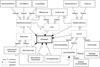 |
Fig. 1 Simplified class diagram in the Unified Modeling Language (UML) that represents the AOT data model. Classes represented with dashed rectangles are abstract and are implemented by the classes that inherit from them. For simplicity, some inner classes have been omitted. The central AOSystem class holds references to the multiple objects in the system, specifically the main telescope itself, a set of one or more wavefront sensors, light sources, wavefront correctors and system loops, and, optionally, a set of atmospheric parameters and scoring cameras. Each of these objects contains a set of specified fields that allow for their extensive description. |
2.2 Data model
In the development of AOT, we designed a data model that attempts to generalise the different parts that may comprise an AO system and their relationships such that it can be used to describe a wide variety of system configurations (including SCAO, SLAO, GLAO, MOAO, LTAO, and MCAO) and different wavefront correction and sensing setups. This data model defines conceptual relationships between the different sets of instruments and their data, with the goal of providing an intuitive and simplified way of accessing data. An overview of this data model can be seen in Fig. 1.
The AOT data model is agnostic both in terms of programming language and specific file format, meaning it can be used as the basis for any implementation of the format. An earlier version of this data model has been discussed in greater detail in Gomes et al. (2022).
2.3 File format
While the AOT data model does not imply any specific file format, in this paper we provide the reference implementation of this data model in a specific file format. Rather than creating our own file format, we believe it is in the best interest of the astronomical community to opt for one that is already commonly used in the community, as that allows us to leverage the high degree of familiarity that astronomers already have with such file formats and the widely available tools for creating, reading and editing them. Therefore, we looked into established file formats that would be able to contain all the necessary data while being easily shareable, namely FITS (Wells & Greisen 1979), HDF5 (The HDF Group 1997-2022), VOTable (Ochsenbein et al. 2004), and ASDF (Greenfield et al. 2015).
Ultimately, we opted to provide an implementation using the FITS standard. The biggest driving factor in this decision was that we aimed to publish AOT data on the ESO Science Archive, which currently only provides full support for this format. Nonetheless, we acknowledge that FITS is an ageing standard that can be a limiting in some particular scenarios (Thomas et al. 2015; Scroggins & Boscoe 2020); therefore there might be interest in implementing the AOT data model using other file formats in the future.
Significant familiarity with FITS is necessary to fully understand the AOT specification described in the following sections, particularly technical terms such as HDU, header, data array, image extensions, and binary tables; we suggest reading the latest FITS specification (at the time of writing; Chiappetti et al. 2018) for the relevant definitions.
3 Data format
A standard AOT file fully adheres to the FITS specification; in other words, a file that follows the AOT standard is also a standard FITS file. An AOT file is composed of one specially formatted primary HDU with no data array (Sect. 3.1), followed by a specific set of binary table extensions (Sect. 3.2) and possibly some image extensions (Sect. 3.3). A single AOT file is capable of supporting all relevant information related to a single telemetry recording. In the following sections, we use a set of AOT-specific conventions (such as the concepts of ‘cross-referencing’ and ‘image reference’) that are defined in Appendix C; these conventions help in describing the data format in detail, and therefore we encourage reading the appendix before the rest of this chapter.
3.1 Primary HDU
The primary HDU in an AOT file contains no data array. However, its header contains a set of keywords that are used to provide metadata about the file and its data in general, as described in Table 1. It is recommended that these keywords are defined in the sequence described in the table, after all the mandatory FITS keyword. Keywords that are not strictly mandatory may be omitted or have null values.
In general, the purpose of the keywords in this header is to serve as an high-level overview of the data contained in the file. Specifically, it offers the user a quick way to check which AO system produced the data, the AO mode being used by that system and the period it was recorded on. It also provides a estimation of the performance of the system during that period, as well as any other notes the system may write regarding its configuration. Finally, it allows the format version to be specified, to avoid any ambiguity in the meaning of the data that may originate from future versions of the specification.
3.2 Binary tables
After the primary HDU, all AOT files should contain a sequence of up to 17 specifically formatted binary table extensions. The names (EXTNAME) of these tables must be
- 1.
AOT_TIME
- 2.
AOT_ATMOSPHERIC_PARAMETERS
- 3.
AOT_ABERRATIONS
- 4.
AOT_TELESCOPES
- 5.
AOT_SOURCES
- 6.
AOT_SOURCES_SODIUM_LGS
- 7.
AOT_SOURCES_RAYLEIGH_LGS
- 8.
AOT_DETECTORS
- 9.
AOT_SCORING_CAMERAS
- 10.
AOT_WAVEFRONT_SENSORS
- 11.
AOT_WAVEFRONT_SENSORS_SHACK_HARTMANN
- 12.
AOT_WAVEFRONT_SENSORS_PYRAMID
- 13.
AOT_WAVEFRONT_CORRECTORS
- 14.
AOT_WAVEFRONT_CORRECTORS_DM
- 15.
AOT_LOOPS
- 16.
AOT_LOOPS_CONTROL
- 17.
AOT_LOOPS_OFFLOAD.
The tables in bold are the ‘mandatory tables’ and they must always exist in the file, even if they contain no rows. The remaining are ‘secondary tables’ and they are related to the mandatory tables with which they share part of the name (e.g. AOT_LOOPS_CONTROL is related to AOT_LOOPS). If an entry in an secondary table shares the UID with an entry in the mandatory table it is related to, then both entries describe the same object: in that case, the mandatory table holds general data about the object, while the secondary table stores data corresponding to the object’s specific sub-type. All secondary tables are optional, meaning that they may be omitted if they would otherwise be empty (that is, if no elements of that particular sub-type exist).
It is strongly recommended that the binary tables in AOT files follow the specified sequence; they are ordered in this way in order to ensure that, when reading sequentially, tables that may be referenced by entries on a certain field have always been read previously. However, the order of the rows inside each table is irrelevant; tables that have the same rows ordered differently are considered equivalent.
In the following sections, we define the purpose of each of these binary table extensions and their contents. It is recommended that all of the specified table fields exist (even if all of their entries are null) and that they follow their defined sequence. An AOT file must adhere to the name and type of each field defined in the tables of these sections (through the TTYPEn and TFORMn keywords, respectively). It is recommended that the data follows the unit of measurement specified in the table and that it is specified through the TUNITn keyword; if an alternative unit of measurement is used, it must be specified through that same keyword. The description of each field (provided in the tables) may be saved in the AOT file through a TCOMMn keyword.
Primary header of an AOT file.
AOT_TIME fields.
3.2.1 AOT_TIME
This binary table allows the user to relate time-varying data to their corresponding progress of time. Specifically, each row in this table specifies moments at which some data points occurred, allowing fields or image extension that describe time-varying data to then directly reference their corresponding row. The fields of this binary table are described in Table 2.
The time instants in this table must be defined through synchronised Unix timestamps and/or through a synchronised frame number such that two data points that occurred simultaneously always share the same timestamp and/or frame number. If in one row both a list of timestamps and frame numbers are provided, they must share the same length.
3.2.2 AOT_ATMOSPHERIC_PARAMETERS
Each row in this binary table describes a set of relevant atmospheric parameters that were obtained from a certain data source. The data source is identified via the UID field and the reference wavelength of the data is defined in WAVELENGTH. Then, time data may be associated via TIME_UID and, for each of those instances, data regarding the overall seeing and conditions of each turbulence layer may also be defined. The list of fields of this binary table is described in Table 3.
3.2.3 AOT_ABERRATIONS
The fields of this binary table are described in Table 4 and they define data that allows for the description of optical aberrations that may exist in different parts of the AO system. Rows may be referenced by wavefront sensors, scoring cameras, or wavefront correctors, and they contain data that define a set of aberrations related to that device.
In each row, the MODES field provides a reference to a 3D image, which is interpreted as a set of n 2D images representing the orthonormal basis of modes for this row. Then, the COEFFICIENTS field provides a reference to a 2D image that contains n columns, each containing the coefficient for that particular basis, with as many rows as necessary to describe the different aberrations that may occur at different field offsets.
The field offsets for these aberrations are specified by the X_OFFSETS and Y_OFFSETS lists, which provide an horizontal and vertical offset for each set of coefficients. For each field offset, the user is able to calculate the overall optical aberration by multiplying each mode basis by its respective coefficients for that field offset, and summing those results. If no field offsets are specified, there may only be one row of coefficients, which is assumed to be representative of the average field offset.
AOT_ATMOSPHERIC_PARAMETERS fields.
AOT_ABERRATIONS fields.
3.2.4 AOT_TELESCOPES
This binary table describes all telescopes in the AO system, with each one being either a main telescope (that is, the telescope performing the observation itself) or a laser launch telescope (LLT; which generates one or more LGSs). There must be exactly one Main Telescope, and all LLTs should be referenced by at least one LGS. The fields of this binary table are described in Table 5.
AOT_TELESCOPES fields.
3.2.5 AOT_SOURCES
This binary table describes all light sources in the system, which may be of four different types: science star, natural guide star, sodium LGS, or Rayleigh LGS. Astronomical coordinates for the sources may be provided. The fields of this binary table are described in Table 6. Sodium and Rayleigh LGS sources may also provide secondary data through Tables 7 and 8, respectively.
3.2.6 AOT_DETECTORS
The fields of this binary table are described in Table 9. Data related to the physical characteristics and configurations of a detector, as well as the actual pixels recorded by it, may be saved in this table. All rows should describe detectors that are referenced by Wavefront Sensors or Scoring Cameras.
3.2.7 AOT_SCORING_CAMERAS
The fields of this binary table are described in Table 10. Some general information about each scoring camera in the system may be provided here. Scoring cameras are able to reference the detector being used and an existing optical aberration.
3.2.8 AOT_WAVEFRONT_SENSORS
This binary table contains data for all wavefront sensors in the system, which may be Shack-Hartmann or Pyramid. Wavefront sensors are able to reference the detector being used and an existing optical aberration. Wavefront sensors may also define the non-common path aberration between them and the science detector. Rows must reference the source that they are sensing. Each wavefront sensor may be referenced by multiple controls loops that interact with it. The fields of this binary table are described in Table 11 and both types of wavefront sensors may also provide secondary data through the Tables 12 or 13.
SUBAPERTURE_MASK, MASK_X_OFFSETS, MASK_Y_OFFSETS and SUBAPERTURE_SIZE together describe the relationship between the detector’s pixels and the wavefront sensor’s subaper-tures. This mechanism is exemplified in Fig. 2.
3.2.9 AOT_WAVEFRONT_CORRECTORS
This binary table contains data for all existing wavefront correctors in the system: linear stages (a correction that is applied in only one axis, usually focus), tip-tilt mirrors (which correct in two axis, tip and tilt), or DMs (which can correct multiple aberrations). Rows in this table may reference relevant optical aberrations that may exist. They must reference the telescope in which the corrector is installed – this may be the main telescope itself, or a LLT (for example, in the case of beam jitter actuators). Each row may be referenced by multiple system loops that command the corrector. The fields of this binary table are described in Table 14. Deformable mirrors may provide secondary data through Table 15.
AOT_SOURCES fields.
AOT_SOURCES_SODIUM_LGS fields.
3.2.10 AOT_LOOPS
This binary table is described in Table 16. Each row aggregates data related to one system loop. In this context, loops are understood as the conceptual mechanism through which the real-time computer (RTC) periodically gathers data from a certain input, performs some calculation in those data, and outputs a set of commands to some sort of wavefront corrector.
Rows may describe ‘control loops’, in which wavefront data (as sensed by a wavefront sensor) are taken as the input, from which the RTC calculates the necessary adjustments to a wave-front corrector (commands), based on interaction and control matrices. Given that control loops must reference the wavefront sensor and wavefront corrector being used (which themselves must reference a source and a telescope, respectively), the data chain related to a control loop can be fully explored through references, allowing the user to study how these elements interact. Secondary data for control loops may be provided through Table 17.
Alternatively, rows may describe ‘offload loops’, which take the set of commands received by one wavefront corrector as the input and, based on an offload matrix, output commands to another wavefront corrector (offloading the commands). Secondary data for such loops may be provided through Table 18.
In the real-world, an AO loop may command multiple wave-front correctors based on a single wavefront sensor, or even multiple wavefront sensors may be used to command a single wavefront corrector (many-to-many relationships). While by design each row in this table can only describe a one-to-one relationship, AOT can still be used to describe many-to-many relationships. This is achieved by creating multiple conceptual loops that represent the same real-world loop, each having different inputs or outputs, as necessary to fully describe the loop1.
AOT_SOURCES_RAYLEIGH_LGS fields.
3.3 Images
In AOT, multi-dimensional data are always stored in images extensions that may be referenced. These image extensions may be contained in the AOT file itself (after all the binary tables), or in separate FITS files (see Appendix C.3).
There are 35 different categories of images that may be referenced, as seen in Table C.1. For each image category, the table specifies the data type, their expected dimensions, their units and a description that characterises the data. In a single AOT file there may be any number of images of the same category and the same image may be referenced by multiple entries. This means that, in cases where different table rows need to reference the exact same multi-dimensional data, it is highly recommended that only a single image extension is created for that data, avoiding data duplication. Images that are never referenced in the file should not be included.
As mentioned in Appendix C.3, each image extension must have a unique non-null name (as set through EXTNAME), which is defined by the user. It is recommended that images are named in a way that allows the file to be self-explanatory. Image extensions must respect the data type (as set through BITPIX) and dimensions (as set through NAXIS) specified in the table. If the unit of measurement of the data in a certain image is not specified (through BUNIT), it is assumed it follows the table specification; if it is different from the specification, the unit must be specified (through BUNIT). Whenever the unit of an image does not follow the specification, it is recommended that it is kept consistent with other images of the same category, as well as related image categories. Users are free to further describe the contents of an image extension through the addition of any user-defined metadata keywords in the header, as long as the FITS specification is respected.
All images may have a t dimension (defined after all the dimensions specified in Table C.1); in such cases, the data in that image is understood to be time-varying. It is recommended that time-varying images contain a TIME_UID keyword in their header, whose value is a AOT_TIME row-reference. This row must have time data of the same length as the t dimension, allowing the user to relate the data to the specific instants it applies to. If an image is not time-varying (e.g. it applies to the entire recording, or it describes average values over the relevant time frame rather than the values at a specific instant), the t dimension may be omitted and the TIME_UID keyword must not be present. Although technically supported, we recommend not saving time-varying images containing AOT_TIME row-references externally (for example, to be used as external image-references, as described in Appendix C.3); this is because the row-reference has no meaning outside the particular AOT file. Overall, external image-references are better suited to avoid data duplication for images that remain unchanged throughout multiple observations (that is, typically images that contain non-time-varying data).
AOT_DETECTORS fields.
AOT_SCORING_CAMERAS fields.
3.4 Extra data
While there are no theoretical obstacles to creating a FITS file that contains extra HDUs, keywords or fields on top of the ones that were already explicitly defined in this specification, tools specially designed to support AOT files may not be expecting such non-standard data. Consequentially, these extra data may be ignored by supporting tools or, in a worst case scenario, cause unexpected behaviour. In order to ensure maximal compatibility, it is highly recommended that such arbitrary modifications are avoided, particularly in files that are meant to be shared with third-parties. If adding some extra metadata is absolutely necessary (for example, to ensure compatibility with existing archives or pipelines), it is recommended that these additions are limited to the primary header.
4 Supporting tools
Given that the usefulness of a format of this kind is largely predicated on its wide adoption, reducing any existing barriers to adoption is of paramount importance. One of the ways user-friendliness can be improved is by providing the community with a set of supporting tools.
In general terms, an AOT supporting tool should provide functionalities that help users read, edit, and write AOT files, while abstracting them from format specification details (such as the layout of the file, table naming, mandatory keywords, and the cross-referencing mechanisms). They may also provide provide translation mechanism for interacting with existing non-AOT telemetry datasets. Since AOT files potentially contain large amounts of data, it is recommended that tools avoid loading all data to memory (and instead load it as it becomes necessary) and that special care is taken to avoid unnecessary data duplication (particularly in image extensions).
The language-agnostic data model for AOT described in Sect. 2.2 enables the abstractions described above while still allowing access to all relevant data. In a previous paper (Gomes et al. 2022), we discussed the development of aotpy (Adaptive Optics Telemetry for Python), an object-oriented Python (Van Rossum & Drake 2009) package based on the AOT data model, which was designed with the considerations described above.
aotpy makes extensive use of the file handling functionalities of Astropy (Astropy Collaboration 2013) and provides a set of functionalities that improve the ease-of-use of the AOT format. In aotpy a recording of AO telemetry data can be described by one Python object (named AOSystem) that contains all the data and relationships between parts of the system (see the data model in Fig. 1).
Using aotpy, an AOT file can be read into a set of related objects (as defined in the data model) that enable the user to interact with the data in a generalised manner. These objects can also be automatically written back into an AOT file, completely abstracting the user from file handling details. These operations are performed by ‘writers’ and ‘readers’, such that one writer-reader pair must exist per each file format supported. while currently only the FITS format is implemented, the package is designed in a modular way that would allow for a simple expansion to further formats. A diagram of the writing and reading process is shown in Fig. 3.
On top of the file handling functionalities, aotpy is also able to translate some existing non-standard data files into a standard aotpy object. This allows the user to handle data from systems that do not follow the AOT specification using aotpy, which is achieved by providing one translation script (‘translator’) for each supported system. These scripts are able to read and interpret the files produced by the respective system, and convert that data into an AOSystem object that describes the recording. This object is system-agnostic and can be treated as any other such AOSystem object, meaning that it can, among other things, be written as a standard AOT FITS file. Currently, we have implemented proof-of-concept translators for ESO’s GALACSI (Ströbele et al. 2012), NAOMI (Aller-Carpentier et al. 2014), CIAO (Kendrew et al. 2012), and ERIS (Riccardi et al. 2016), as well as ALPAO’s PAPYRUS (Muslimov et al. 2021). A diagram exemplifying the translation process can be seen in Fig. 4.
We have made aotpy publicly available on PyPI (Python Package Index) and its source code is also available on GitHub and Zenodo (Gomes 2023; Gomes & Leroux 2023).
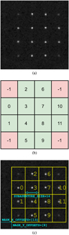 |
Fig. 2 Diagram showing how the relationship between wave-front sensor subapertures and detector pixels can be deduced from SUBAPERTURE_MASK, MASK_X_OFFSETS, MASK_Y_OFFSETS and SUBAPERTURE_SIZE. Panel a: example 80 × 80 PIXEL_INTENSITIES image from the wavefront sensor’s detector. Panel b: example 4 × 4 SUBAPERTURE_MASK for a wavefront sensor with 12 valid subapertures. Cells with value −1 indicate an invalid subaperture, while the others indicate the index of that subaperture in the sensor data.. Panel c: SUBAPERTURE_MASK superimposed over PIXEL_INTENSITIES. In this case, MASK_X_OFFSETS and MASK_Y_OFFSETS have length one, indicating that the mask is superimposed once, and its lowermost positions in X and Y are 13 and 8, respectively. SUBAPERTURE_SIZE defines each subaperture as corresponding to 16 pixels. |
AOT_WAVEFRONT_SENSORS fields.
AOT_WAVEFRONT_SENSORS_SHACK_HARTMANN fields.
AOT_WAVEFRONT_SENSORS_PYRAMID fields.
AOT_WAVEFRONT_CORRECTORS fields.
AOT_WAVEFRONT_CORRECTORS_DM fields.
AOT_LOOPS fields.
AOT_LOOPS_CONTROL fields.
AOT_LOOPS_OFFLOAD fields.
 |
Fig. 3 Diagram that exemplifies how ‘readers’ and ‘writers’ work in aotpy. The starting and final ‘AOT.fits’ files are functionally equivalent. The AOSystem object is completely agnostic from the specific file format in use, meaning that it would be possible to read a FITS file and write an equivalent file in another file format, as long as such a writer was implemented. |
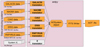 |
Fig. 4 Diagram that exemplifies how ‘translators’ work in aotpy. The files to the left are non-standard and can be in any format (or even multiple formats). Each system requires a specific translator that is able to interpret data from their respective files and fill the corresponding fields of the AOSystem object. This resulting object is completely agnostic from the system where the data originated from, and it can then be used as any other aotpy object. In this example, it is written back into a single AOT .fits file using the FITS writer. |
5 Demonstration and data availability
In the interest of allowing users to have an immediate experience with AOT files, we made available some proof-of-concept files. Following the process described in Sect. 4, we translated datasets from multiple systems into sets of AOT files. After translating these datasets, we made them available on online archives that follow the FAIR principles (Wilkinson et al. 2016). Namely, data gathered by ESO on the GALACSI, CIAO, NAOMI, and ERIS AO systems (under ESO’s programme IDs 60.A-9278(B), 60.A-9278(C), 60.A-9278(D), and 60.A-9278(E), respectively) was translated and published on the ESO archive2. This archive follows the International Virtual Observatory Alliance (IVOA) architecture (Arviset et al. 2012) and requires a few ESO-specific keywords to be added to the primary header of the AOT files in order to make them findable. These keywords are handled by aotpy; for example, we could convert a set of ERIS data contained in a folder located at ‘path/to/folder’ into a single ‘example.fits’ AOT file with the following code:
from aotpy.translators import ERISTranslator
t = ERISTranslator(‘path/to/folder’)
t.add_archive_metadata()
t.system.write_to_file(‘example.fits’).
A small set of files has also been made available on Zenodo (Gomes et al. 2023); these files contain PAPYRUS data, along with a subset of the data also shared through the ESO archive. This demonstration shows the adaptability of the format to vastly different systems, including different telescopes, different AO modes, different wavefront sensor types and different control schemes.
In Morujão et al. (2023), NAOMI AO telemetry data (made available by this project) is used to estimate integrated turbulence parameters, fully demonstrating the suitability of AOT for such use cases. The PSF-R use case is still in development and a full demonstration is not available at this time. We are supporting the developments made under the Extremely Large Telescope (ELT) working group for PSF-R3 in all its dimensions, namely with demonstrations on the Very Large Telescope with ERIS in preparation for the full-blown deployment on the ELT.
6 Summary and outlook
In this paper we highlight the immense scientific potential within the field of AO research. We address the challenge of limited end-user access to pertinent data. Despite a growing interest for data-producing systems to share their valuable data, the community has yet to establish a consensus on the most effective approach. To overcome this challenge, we introduce AOT, an innovative data exchange format that has been collaboratively developed within the community. AOT is designed to accommodate a wide range of system configurations, empowering us to unlock the full potential of AO research.
AOT is focused on supporting scientifically important use cases through a set of design principles that address the needs of the community. It is a FITS-based format, on top of which we have developed a set of conventions and structures that enable users to access relevant data in a standardised manner. This format is fully specified in order to avoid ambiguity and allow for interchangeability.
We have discussed the need to provide the community with supporting tools that ease the adoption of the format. We have demonstrated their use and provide public datasets.
Our aim with this first public version of AOT is to get a significant foothold in the AO space while acknowledging that future expansions may be necessary as the field progresses and community needs change. Therefore, we are committed to providing continuous support and improvements in the foreseeable future. Looking ahead, our foremost objectives include:
Continue developing and improving supporting tools and their documentation. We are currently in the early stages of developing a graphical user interface for AOT data, with the goal of providing a dashboard that allows users to perform exploratory data analysis interactively. In conjunction with the ESO archive team, we are also developing new user-facing query forms that improve access to AOT data in the archive.
Further promoting and discussing the format with both end-users and data-producing teams. We have initiated talks with other instrument teams, including the teams responsible for Keck AO (Wizinowich et al. 2000), LBT AO (Skemer et al. 2012), NFIRAOS (Herriot et al. 2005), HARMONI (Thatte et al. 2010), MICADO (Davies et al. 2010), and METIS (Brandl et al. 2008), to explore the possibility of also providing translation scripts for those systems; this diversification would further exemplify AOT’s adaptability to different AO configurations. We are also exploring how AOT/aotpy can be integrated into data processing pipelines currently in use by AO instruments.
Exploring and demonstrating the usefulness of AOT in additional scenarios such as AIT (Assembly, Integration and Test) phases, ELT-class telescopes, high-contrast imaging, and interferometry.
All in all, in the coming phases, the pivotal focus will be on establishing and maintaining enduring community support and funding for the AOT software package and ensuring its continuous development to meet the evolving needs of future scientific instruments and observatories. Transitioning from the current proof-of-concept phase to a fully operational setting will be instrumental in realising the adoption of AOT by the next generation of state-of-the-art instruments. Sustained financial and community backing will play an essential role in this endeavour.
Acknowledgements
This project has received funding from the European Union’s Horizon 2020 research and innovation programme under grant agreement no. 101004719 (OPTICON–RadioNet Pilot) and from the FCT – Fundação para a Ciência e a Tecnologia through the grant CENTRA UIDB/00099/2020. C.M. Correia acknowledges the financial support provided by FCT with grant 2022.01293.CEECIND.
Appendix A Design principles
In order to guide the necessary decision-making for designing the format, we deem that a set of design principles must be defined. These principles essentially illustrate the characteristics of a format that would best meet the goals of this format. Specifically, this idealised format would be:
Shareable: Exchanging data between data-producing systems and their end-users must be a straightforward process.
Unambiguous: Ensure that data shared can only be interpreted in one well-defined manner, which is consistent across all systems.
Generalised: Structure the format in a way that allows the end-user to access data abstracted from observatory or instrument details.
Flexible: Support as many AO systems as possible, by being sufficiently adaptable to their differences and the irregularities of real-life telemetry.
Complete: Ensure that all relevant information can be packaged in the format.
User-friendly: Adoption barriers must be reduced by providing accessible tools and documentation.
Expansible: Allow for future expansions to meet user needs and advancements in the AO field.
In sum, the format structure and data access should be the exact same across various systems and configurations, while the data itself should be trivial to access and understand. Given that some of these design principles can conflict with each-other, in practice it is not possible to perfectly achieve all of them. Therefore, some design decisions have to be analysed as compromises between different principles. In general, we consider these principles should be prioritised in the listed order.
Appendix B Multi-dimensional data in AOT
While the FITS specification technically supports storing multidimensional data in binary tables, this feature has many limitations. The specification defines that, in order for a certain field to contain multi-dimensional entries, this field must have a corresponding TDIMn keyword that defines the exact dimensions of its arrays. While the array itself is still stored as a 1D set of data, knowing its intended dimensions allows for a proper interpretation of the data.
Since we must only define one such keyword per field, a direct consequence is that all the entries in that field must have the exact same dimensions4. Using AOT as an example, this means that if we wanted to store the slopes of a certain wave-front sensor as a multi-dimensional array inside the binary table, slopes of all further wavefront sensors would also need to respect those exact dimensions. However, it is not guaranteed that they would have the same dimensions, as the number of subapertures might not be the same, or we might be recording at a different frequency. Therefore, it is clear that the standard implementation of multi-dimensional data in binary tables is not versatile enough to fit AOT’s needs.
Since we had to store multi-dimensional data in some way, we considered three ways of getting around this limitation:
Use TDIMn keywords and, for each field, pick a large enough set of dimensions such that the data from all entries can fit inside those dimensions. Fill the remaining spaces with some sort of filler value that is ignored when reading.
Use variable-length arrays (VLAs) without TDIMn keywords, and add an extra column that specifies the dimensions for each entry.
Save the multi-dimensional data as separate image extensions that are then referenced in the corresponding table entries.
The first option has multiple issues. First off, it can result in large amounts of wasted storage space given that a user could be forced to write a small array as a much larger one, in order to respect the dimensions that were set by another array in that field. On top of that, defining an appropriate filler value could be difficult given how diverse the data can be. It is also completely non-intuitive for any users that would see such data without context, as the FITS specification would likely lead them to interpret all entries as having the dimensions specified by TDIMn. Finally, the implementation complexity for this would be relatively large, forcing reading and writing tools to filter and reshape possibly huge amounts of data in order to correctly interpret it.
By using VLAs, the second option avoids the wasted space that the first option would create. However, it would force the creation of one extra field for any field that contains multidimensional data, which is a mechanism that is not standardised in FITS. Therefore, the interpretation of this field would be ambiguous for users not familiar with the AOT standard (for example, are the arrays be stored in row-major or column-major order?), which could lead to interchangeability issues.
We ended up choosing the third option. The major deciding factor is that saving multi-dimensional data in image extensions is a very well-defined mechanism, since it is fully described in the FITS specification. Using image extensions also allows us to leverage their already established features and versatility, such as saving metadata in its headers or using data scaling features. Another advantage is that FITS tools are usually already prepared to deal with image extensions and thus they can easily and unambiguously interpret them without requiring any AOT-specific conventions. Finally, this approach also allows us to save multi-dimensional data externally through FITS image files, which is a very common mechanism. The biggest downside of using this approach is that it requires AOT to use a non-standard cross-referencing mechanism. However, the format already required a similar mechanism to deal with the cross-referencing between binary tables (see Appendix C.3); therefore, this did not represent a significant increase in AOT’s complexity.
It is important to note that some fields in AOT contain 1D arrays that may have a length larger than 1 (that is, lists). While such data could reasonably be stored as 1D image extensions, we deem doing so would create unnecessary clutter in the file structure. This is because 1) these sets of data tend to be relatively small and fairly simple, so they are unlikely to benefit significantly from the metadata of image extensions and 2) the standard VLAs are able to fully describe these lists without requiring any AOT-specific convention. Therefore, in fields where 1D arrays are expected, AOT uses VLAs.
Appendix C AOT conventions
In this appendix we define a set of AOT-specific conventions that apply to the entirety of this paper. Where relevant, some standard FITS conventions will also be mentioned, but we do not cover the entirety of the FITS specification; it is implicit that all FITS features are supported, unless explicitly defined otherwise.
Appendix C.1 Mandatory FITS keywords
The FITS specification defines a set of mandatory keywords (Chiappetti et al. 2018, Section 4.4.1.) for both the primary and extension headers. For simplicity, in this paper we only explicitly define AOT-specific keywords for each HDU, but the mandatory FITS keywords are implicitly assumed to be present and appropriately adhered to.
Appendix C.2 Data types
While the FITS specification allows a wide range of possible data types (see Chiappetti et al. 2018, particularly Sections 4.2., 5. and 7.3.), in AOT only four different types of data are used: (1) an integer, represented as ‘int’, (4) a floating point, represented as ‘flt’, (3) a string, represented as ‘str’, and (4) a list of floatingpoint data, represented as ‘lst’. Header values are either str or flt. Image data may be int or flt. Fields in binary tables may be int, flt, str (represented as a fixed-length array of characters) or lst (represented as a VLA of floats). AOT does not specify the precision for any of the data types; this means that a field or image specified as, for example, flt may be represented with single (32bit) or double (64-bit) precision, according to the user’s needs (so long as the FITS specification is properly adhered to).
Although the FITS specification technically allows binary table fields of any data type to contain multi-dimensional arrays, this functionality is not used in AOT and thus all data within AOT binary tables must be uni-dimensional (for the reasoning, see Appendix B). As a result, all multi-dimensional data in AOT is contained in image extensions that are cross-referenced via table entries (this mechanism is explained in Appendix C.3).
Appendix C.3 Cross-referencing
The FITS specification does not provide a standard way of cross-referencing image extensions or table rows. Given that such a mechanism would be convenient for defining relationships between data and avoiding data duplication, AOT defines its own cross-referencing mechanism. A diagram demonstrating its use can be seen in Fig. C.1.
In general, there are two different types of references in AOT: ‘row-references’ and ‘image-references’. Both types of references are done through a single str value, in a field that is specified as being a reference. This str value is able to uniquely and unambiguously identify the referenced row or image extension. A null str in a reference field is interpreted as no reference being made (see Appendix C.4).
A row-reference identifies a specific row of a certain binary table. All AOT tables contain one UID field, for which all the entries must have a non-null value that is unique within each table (see Sect. 3.2). This means that we can uniquely identify any row as long as we know its UID and the table it belongs to. Given that AOT specifies which table is being referenced in every row-reference field, a row-reference is made unambiguously with a str value formatted as ’ROWREF<row_UID>’, where row_UID is the UID of the row being referenced.
An image-reference identifies a certain image extension. The referenced extension should be present either in the AOT file itself (internal image-reference) or in another FITS file (external image-reference), but must always follow the specifications of one of the image categories defined in Sect. 3.3. All image extensions present in the AOT file must have a unique non-null name (EXTNAME keyword), allowing them to be referenced internally by a str value formatted as ’INTREF<image_EXTNAME>’, where image_EXTNAME is the name of the image extension being referenced.
An external image-reference identifies the FITS file where a certain image extension is present, either through a file name (file image-reference) or through a web address (URL image-reference). A file image-reference is made through a str value formatted as ’FILEREF<filename.fits>index’, where filename is the name of the FITS file where the image data are located. To ensure wide compatibility across most commonly used file systems, filename must be case-sensitive and only contain alphanumeric characters, full stops (.), underscores (_) and hyphens (−). It is recommended that, when file image-references are used, the referenced file is somehow made available along with the AOT file, such that it is unambiguously be referenced solely by its name. An URL image-reference is made through a str value formatted as ’URLREF<url>index’, where url is an URL (as defined in Berners-Lee et al. 2005) to a FITS file. It is highly recommended that this file is publicly accessible and that it is not ephemeral; in other words, the file should remain accessible through this URL by anyone for as long as the data are relevant. For both types of external image-references, index is a non-negative integer that indicates the position of the HDU that contains the referenced image data (where index 0 is the primary HDU, index 1 is the first extension, and so on). index ‘may’ be omitted as long as the referenced image data are present in the first HDU that contains non-null image data.
Given the challenges associated with guaranteeing that an external image extension always remains unambiguously accessible throughout the useful lifetime of its data, we highly recommend that external image-references are only used in exceptional scenarios where saving an image internally would be impossible or unmanageable (e.g. instances where avoiding data duplication is a critical concern, restrictions imposed by archiving policies or file size limitations). We also highly discourage the use of URL image-references for data stored in services that are not designed for continuous long-term access, such as cloud storage, file-sharing websites, or any service for which the URL may expire; if an URL image-references must be used, we recommend linking to an astronomical archive.
While the values of both the EXTNAME keywords and the UID entries are freely defined by the user, it is highly recommended that these values be human-readable and intuitively describe the set of data that they correspond to. This is beneficial to the readability of the file, as it helps make it self-explanatory. For example, we recommend the UID of a Telescope row to be the name of the telescope itself.
Appendix C.4 Null values
Since AOT defines a wide set of data, we expect that users might not want to fill all of the available fields. Therefore, with the exception of the mandatory FITS keywords (Appendix C.1), the fields necessary for uniquely identifying references (Appendix C.3) and other keywords defined as strictly mandatory in Secs. 3.1 or 3.2, all values are considered to be nullable.
While the FITS specification allows for keywords in headers to have values of indeterminate data type (undefined keywords), to avoid confusion this is strictly disallowed in AOT. Therefore, null strings must be represented as zero-length arrays of characters (KEYWORD = ’ ’; see Sect. 4.2.1.1 of Chiappetti et al. 2018 for a detailed distinction).
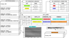 |
Fig. C.1 Diagram demonstrating how the cross-referencing mechanism in AOT works. In this example, each row in the AOT_LOOPS table references one row in the AOT_WAVEFRONT_SENSORS table, one row in the AOT_WAVEFRONT_CORRECTORS table and one image extension. Rows are identified by the string value of their UID fields, while images are identified by the string value of their EXTNAME keyword. |
FITS specifies that null values in binary tables are represented in different ways depending on their specific data type:
Null str data must be represented by an array of characters where the first character is the ASCII NULL character (0x00), in other words, a zero-length null-terminated string.
In order for null int data to exist in a certain field, that field must have a TNULLn value specified by the user; all entries containing that exact value are then interpreted as null. Given that all integer fields in the AOT standard describe counts, negative integer values inherently have no meaning and thus are recommended for this purpose (assuming a signed representation).
For null flt values, the IEEE special value NaN must be used.
Null lst are specified by having an array length of 0, and should be interpreted as an empty array rather than a non-existing one (see Sects. 7.3.5. and 7.3.6. of Chiappetti et al. 2018).
If a user does not intend to provide data for a field that references an image, it is preferable to use a null reference, rather than referencing an image extension that contains no data.
Appendix C.5 Date and time representation
Date and time data are vital for interpreting AO telemetry data; accordingly AOT supports associating date and time data to all time-sensitive and/or time-varying sets of data. All date and time data in AOT must be in the UTC time standard, and must be represented in one of two ways (depending on the specific field): 1) Based on the ISO 8601 format or 2) Unix timestamp.
ISO 8601 provides a set of unambiguous ways of representing calendar dates and times in a human-readable format. In AOT, we use a ISO 8601 derived format where date and time are represented as a string in the pattern <date>T<time> with <date> being specified as YYYY-MM-DD and <time> specified as hh:mm:ss[.SSSSSS] (the decimal part, in square brackets, is optional). This format is used where a single timestamp is expected, for its human-readability. No other ISO 8601 formats are supported.
In situations where a set of timestamps is expected (for example, timestamps related to time-varying data) the Unix time format (also known as POSIX or epoch time) is used instead. This format represents date and time as a floating-point value containing the number of seconds that have elapsed since 00:00:00 UTC on 1 January 1970, with decimal digits being allowed. Dates past 03:14:08 UTC on Tuesday, 19 January 2038, cannot be represented by 32-bit floats (due to overflow); in such cases, 64-bit floats must be used.
Appendix C.6 Table of AOT image categories
Possible image categories.
Appendix C.7 Geometric transformations
Using homogeneous coordinates, any combination of translation, reflection, scale, rotation and shearing (affine transformations) can be described via a single 3 × 3 matrix M such that P′ = MP, where P is a ![Mathematical equation: $\left[ {\matrix{ {x\,\,\,\,\,y\,\,\,\,\,1} \cr } } \right]$](/articles/aa/full_html/2024/06/aa48486-23/aa48486-23-eq2.png) vector (with x and y being the original horizontal and vertical coordinates, respectively) and P′ is a
vector (with x and y being the original horizontal and vertical coordinates, respectively) and P′ is a ![Mathematical equation: $\left[ {\matrix{ {x'\,\,\,\,\,y'\,\,\,\,\,1} \cr } } \right]$](/articles/aa/full_html/2024/06/aa48486-23/aa48486-23-eq3.png) vector, where x′ and y′ are the transformed coordinates (see Rogers & Adams 1989, section 2-15).
vector, where x′ and y′ are the transformed coordinates (see Rogers & Adams 1989, section 2-15).
All geometric information in AOT must be described relative to the same reference origin point (defined by the user), from which transformations ‘may’ occur. For example, if the geometry of the system is defined with the telescope pupil as the reference point, the TRANFORMATION_MATRIX on the corresponding AOT_TELESCOPES row will be a 3-by-3 identity matrix. Then, a wavefront sensor may define a 90° rotation from the pupil with a ![Mathematical equation: $\left[ {\matrix{ 0 & { - 1} & 0 \cr 1 & 0 & 0 \cr 0 & 0 & 1 \cr } } \right]$](/articles/aa/full_html/2024/06/aa48486-23/aa48486-23-eq4.png) matrix. The detector used by that wavefront sensor, if not rotated in regards to it, would define its geometry by referencing the exact same matrix.
matrix. The detector used by that wavefront sensor, if not rotated in regards to it, would define its geometry by referencing the exact same matrix.
References
- Aller-Carpentier, E., Dorn, R., Delplancke-Stroebele, F., et al. 2014, in Optical and Infrared Interferometry IV, eds. J. K. Rajagopal, M. J. Creech-Eakman, & F. Malbet, International Society for Optics and Photonics (SPIE), 9146, 91461C [NASA ADS] [Google Scholar]
- Andrade, P. P., Garcia, P. J., Correia, C. M., Kolb, J., & Carvalho, M. I. 2019, MNRAS, 483, 1192 [CrossRef] [Google Scholar]
- Arviset, C., Gaudet, S., & IVOA Technical Coordination Group 2012, in European Planetary Science Congress 2012, EPSC2012-626 [Google Scholar]
- Astropy Collaboration (Robitaille, T. P., et al.) 2013, A&A, 558, A33 [NASA ADS] [CrossRef] [EDP Sciences] [Google Scholar]
- Bardou, L. & Schulz, C. 2018a, ESO Science Archive – Wendelstein Laser Guide Star Unit Data Products, https://archive.eso.org/wdb/wdb/eso/wlgsu/form, accessed: 2022-07-02 [Google Scholar]
- Bardou, L., & Schulz, C. 2018b, Manual for the open loop LGS-AO data taken with elongated LGS in ELT geometry configuration, https://archive.eso.org/wdb/help/eso/WLGSU_CANARY_AO_Manual.pdf, accessed: 2022-07-02 [Google Scholar]
- Bardou, L., Gendron, É., Rousset, G., et al. 2021, A&A, 649, A158 [NASA ADS] [CrossRef] [EDP Sciences] [Google Scholar]
- Beltramo-Martin, O., Correia, C. M., Mieda, E., et al. 2018, MNRAS, 478, 4642 [NASA ADS] [CrossRef] [Google Scholar]
- Beltramo-Martin, O., Correia, C. M., Ragland, S., et al. 2019, MNRAS, 487, 5450 [NASA ADS] [CrossRef] [Google Scholar]
- Beltramo-Martin, O., Marasco, A., Fusco, T., et al. 2020, MNRAS, 494, 775 [Google Scholar]
- Berners-Lee, T., Fielding, R. T., & Masinter, L. M. 2005, Uniform Resource Identifier (URI): Generic Syntax, RFC 3986 [Google Scholar]
- Bradner, S. O. 1997, Key words for use in RFCs to Indicate Requirement Levels, RFC 2119 [Google Scholar]
- Brandl, B. R., Lenzen, R., Pantin, E., et al. 2008, in Ground-based and Airborne Instrumentation for Astronomy II, eds. I. S. McLean, & M. M. Casali, International Society for Optics and Photonics (SPIE), 7014, 70141N [NASA ADS] [Google Scholar]
- Chiappetti, L., Currie, M. J., Allen, S., et al. 2018, Definition of the Flexible Image Transport System (FITS) The FITS Standard, Version 4.0: updated 2016 July 22 by the IAUFWG Original document publication date: 2016 July 22 Language-edited document publication date: 2018 August 13, Tech. rep., Italian National Institute for Astrophysics (INAF) [Google Scholar]
- Conan, R., & Correia, C. 2014, in Adaptive Optics Systems IV, SPIE, 9148, 2066 [NASA ADS] [Google Scholar]
- Davies, R., Ageorges, N., Barl, L., et al. 2010, in Ground-based and Airborne Instrumentation for Astronomy III, eds. I. S. McLean, S. K. Ramsay, & H. Takami, International Society for Optics and Photonics (SPIE), 7735, 77352A [NASA ADS] [Google Scholar]
- Duvert, G., Young, J., & Hummel, C. A. 2017, A&A, 597, A8 [NASA ADS] [CrossRef] [EDP Sciences] [Google Scholar]
- Fusco, T., Bacon, R., Kamann, S., et al. 2020, A&A, 635, A208 [NASA ADS] [CrossRef] [EDP Sciences] [Google Scholar]
- Gendron, E., Clénet, Y., Fusco, T., & Rousset, G. 2006, A&A, 457, 359 [NASA ADS] [CrossRef] [EDP Sciences] [Google Scholar]
- Gilles, L., Correia, C., Véran, J.-P., Wang, L., & Ellerbroek, B. 2012, Appl. Opt., 51, 7443 [NASA ADS] [CrossRef] [Google Scholar]
- Gomes, T. 2023, https://github.com/STAR-PORT/aotpy [Google Scholar]
- Gomes, T., & Leroux, F. 2023, https://doi.org/10.5281/zenodo.8187229 [Google Scholar]
- Gomes, T., Correia, C., Bardou, L., et al. 2022, in Adaptive Optics Systems VIII, eds. L. Schreiber, D. Schmidt, & E. Vernet, International Society for Optics and Photonics (SPIE), 12185, 121850H [NASA ADS] [Google Scholar]
- Gomes, T., Garcia, P., Correia, C., & Morujâo, N. 2023, https://doi.org/10.5281/zenodo.8192741 [Google Scholar]
- Greenfield, P., Droettboom, M., & Bray, E. 2015, Astron. Comput., 12, 240 [NASA ADS] [CrossRef] [Google Scholar]
- Guesalaga, A., Neichel, B., Cortés, A., Béchet, C., & Carmine, G. 2014, MNRAS, 440, 1925 [NASA ADS] [CrossRef] [Google Scholar]
- Herriot, G., Hickson, P., Ellerbroek, B. L., et al. 2005, in Astronomical Adaptive Optics Systems and Applications II, eds. R. K. Tyson, & M. Lloyd-Hart, International Society for Optics and Photonics (SPIE), 5903, 590302 [Google Scholar]
- Hirst, P., & Cardenes, R. 2016, in Software and Cyberinfrastructure for Astronomy IV, eds. G. Chiozzi & J. C. Guzman, International Society for Optics and Photonics (SPIE), 9913, 531 [NASA ADS] [Google Scholar]
- Hirst, P., Jenkins, D., & Sivo, G. 2020, in Adaptive Optics Systems VII, eds. L. Schreiber, D. Schmidt, & E. Vernet, International Society for Optics and Photonics (SPIE), 11448 [Google Scholar]
- Jolissaint, L., Ragland, S., Christou, J., & Wizinowich, P. 2018, Appl. Opt., 57, 7837 [CrossRef] [Google Scholar]
- Kendrew, S., Hippler, S., Brandner, W., et al. 2012, in Ground-based and Airborne Instrumentation for Astronomy IV, eds. I. S. McLean, S. K. Ramsay, & H. Takami, International Society for Optics and Photonics (SPIE), 8446, 84467W [NASA ADS] [Google Scholar]
- Laidlaw, D. J., Osborn, J., Morris, T. J., et al. 2019, MNRAS, 491, 1287 [NASA ADS] [Google Scholar]
- Martin, O. A., Correia, C. M., Gendron, E., et al. 2016, in Adaptive Optics Systems V, eds. E. Marchetti, L. M. Close, & J.-P. Véran, International Society for Optics and Photonics (SPIE), 9909, 1143 [Google Scholar]
- Morujão, N., Correia, C., Andrade, P., Woillez, J., & Garcia, P. 2023, A&A, 678, A193 [NASA ADS] [CrossRef] [EDP Sciences] [Google Scholar]
- Muslimov, E., Levraud, N., Chambouleyron, V., et al. 2021, in Optical Instrument Science, Technology, and Applications II, eds. N. Haverkamp, B. N. Sitarski, & R. N. Youngworth, International Society for Optics and Photonics (SPIE), 11876, 118760H [Google Scholar]
- Myers, R. M., Hubert, Z., Morris, T. J., et al. 2008, in Adaptive Optics Systems, eds. N. Hubin, C. E. Max, & P. L. Wizinowich, International Society for Optics and Photonics (SPIE), 7015, 52 [Google Scholar]
- Ochsenbein, F., Williams, R., Davenhall, C., et al. 2004, in Toward an International Virtual Observatory, eds. P. J. Quinn & K. M. Górski, ESO ASTROPHYSICS SYMPOSIA (Springer), 118 [CrossRef] [Google Scholar]
- Pauls, T. A., Young, J. S., Cotton, W. D., & Monnier, J. D. 2004, in New Frontiers in Stellar Interferometry, 5491 (International Society for Optics and Photonics), 1231 [NASA ADS] [CrossRef] [Google Scholar]
- Pauls, T. A., Young, J. S., Cotton, W. D., & Monnier, J. D. 2005, PASP, 117, 1255 [NASA ADS] [CrossRef] [Google Scholar]
- Petit, C., Sauvage, J.-F., Fusco, T., et al. 2014, in Adaptive Optics Systems IV, 9148, SPIE, 214 [Google Scholar]
- Preston-Werner, T. 2013, Semantic Versioning 2.0.0, https://semver.org/spec/v2.0.0.html, accessed: 2023-01-24 [Google Scholar]
- Riccardi, A., Esposito, S., Agapito, G., et al. 2016, in Adaptive Optics Systems V, eds. E. Marchetti, L. M. Close, & J.-P. Véran, International Society for Optics and Photonics (SPIE), 9909, 99091B [NASA ADS] [Google Scholar]
- Rogers, D. F., & Adams, J. A. 1989, Mathematical Elements for Computer Graphics, 2nd edn. (USA: McGraw-Hill, Inc.) [Google Scholar]
- Scroggins, M., & Boscoe, B. M. 2020, IEEE Ann. Hist. Comput., 42, 42 [NASA ADS] [CrossRef] [Google Scholar]
- Sinquin, B., Prengere, L., Kulcsár, C., et al. 2020, MNRAS, 498, 3228 [NASA ADS] [CrossRef] [Google Scholar]
- Sivo, G., Kulcsár, C., Conan, J.-M., et al. 2014, Opt. Express, 22, 23565 [NASA ADS] [CrossRef] [Google Scholar]
- Skemer, A. J., Hinz, P. M., Esposito, S., et al. 2012, ApJ, 753, 14 [Google Scholar]
- Ströbele, S., Penna, P. L., Arsenault, R., et al. 2012, in Adaptive Optics Systems III, eds. B. L. Ellerbroek, E. Marchetti, & J.-P. Véran, International Society for Optics and Photonics (SPIE), 8447, 844737 [CrossRef] [Google Scholar]
- Thatte, N., Tecza, M., Clarke, F., et al. 2010, in Ground-based and Airborne Instrumentation for Astronomy III, eds. I. S. McLean, S. K. Ramsay, & H. Takami, International Society for Optics and Photonics (SPIE), 7735, 77352I [NASA ADS] [Google Scholar]
- The HDF Group 1997-2022, Hierarchical Data Format, version 5, https://www.hdfgroup.org/HDF5/, accessed: 2022-06-27 [Google Scholar]
- Thomas, B., Jenness, T., Economou, F., et al. 2015, Astron. Comput., 12, 133 [NASA ADS] [CrossRef] [Google Scholar]
- Van Rossum, G., & Drake, F. L. 2009, Python 3 Reference Manual (Scotts Valley, CA: CreateSpace) [Google Scholar]
- Veran, J. P., Rigaut, F., Maitre, H., & Rouan, D. 1997, J. Opt. Soc. Am. A, 14, 3057 [CrossRef] [Google Scholar]
- Vidal, F., Gendron, E., & Rousset, G. 2010, J. Opt. Soc. Am. A, 27, A260000 [Google Scholar]
- Wells, D. C., & Greisen, E. W. 1979, in Image Processing in Astronomy, 445 [Google Scholar]
- Wilkinson, M. D., Dumontier, M., Aalbersberg, I. J., et al. 2016, Scientific Data, 3, 1 [CrossRef] [Google Scholar]
- Wizinowich, P., Acton, D. S., Shelton, C., et al. 2000, PASP, 112, 315 [NASA ADS] [CrossRef] [Google Scholar]
For example, if a real-world AO loop uses a single wavefront sensor to command multiple wavefront correctors, we can have one control loop row for each wavefront corrector being commanded. These rows will all reference the same wavefront sensor as input, but their output wavefront corrector will differ, as will the control matrices and commands accordingly. The overhead for this is minimal, given that the duplicated data will be composed almost entirely of references.
These datasets are now publicly accessible and searchable under the respective programme IDs. Queries on the ESO archive can be performed at https://archive.eso.org/eso/eso_archive_main.html. The ‘Program ID’ textbox can be used to specify the instrument.
There is one exception to this: fields containing multi-dimensional data formatted as VLAs. In this case, their entries may either adhere to the specified dimensions or be empty entries (length 0). This is a very obscure detail that is currently unsupported by most FITS tools. Regardless, this feature is not particularly useful for the situation at hand, as VLAs provide no mechanism for defining different dimensions per entry, and thus there is no meaningful space savings to be had.
All Tables
All Figures
|
Fig. 1 Simplified class diagram in the Unified Modeling Language (UML) that represents the AOT data model. Classes represented with dashed rectangles are abstract and are implemented by the classes that inherit from them. For simplicity, some inner classes have been omitted. The central AOSystem class holds references to the multiple objects in the system, specifically the main telescope itself, a set of one or more wavefront sensors, light sources, wavefront correctors and system loops, and, optionally, a set of atmospheric parameters and scoring cameras. Each of these objects contains a set of specified fields that allow for their extensive description. |
| In the text | |
|
Fig. 2 Diagram showing how the relationship between wave-front sensor subapertures and detector pixels can be deduced from SUBAPERTURE_MASK, MASK_X_OFFSETS, MASK_Y_OFFSETS and SUBAPERTURE_SIZE. Panel a: example 80 × 80 PIXEL_INTENSITIES image from the wavefront sensor’s detector. Panel b: example 4 × 4 SUBAPERTURE_MASK for a wavefront sensor with 12 valid subapertures. Cells with value −1 indicate an invalid subaperture, while the others indicate the index of that subaperture in the sensor data.. Panel c: SUBAPERTURE_MASK superimposed over PIXEL_INTENSITIES. In this case, MASK_X_OFFSETS and MASK_Y_OFFSETS have length one, indicating that the mask is superimposed once, and its lowermost positions in X and Y are 13 and 8, respectively. SUBAPERTURE_SIZE defines each subaperture as corresponding to 16 pixels. |
| In the text | |
|
Fig. 3 Diagram that exemplifies how ‘readers’ and ‘writers’ work in aotpy. The starting and final ‘AOT.fits’ files are functionally equivalent. The AOSystem object is completely agnostic from the specific file format in use, meaning that it would be possible to read a FITS file and write an equivalent file in another file format, as long as such a writer was implemented. |
| In the text | |
|
Fig. 4 Diagram that exemplifies how ‘translators’ work in aotpy. The files to the left are non-standard and can be in any format (or even multiple formats). Each system requires a specific translator that is able to interpret data from their respective files and fill the corresponding fields of the AOSystem object. This resulting object is completely agnostic from the system where the data originated from, and it can then be used as any other aotpy object. In this example, it is written back into a single AOT .fits file using the FITS writer. |
| In the text | |
|
Fig. C.1 Diagram demonstrating how the cross-referencing mechanism in AOT works. In this example, each row in the AOT_LOOPS table references one row in the AOT_WAVEFRONT_SENSORS table, one row in the AOT_WAVEFRONT_CORRECTORS table and one image extension. Rows are identified by the string value of their UID fields, while images are identified by the string value of their EXTNAME keyword. |
| In the text | |
Current usage metrics show cumulative count of Article Views (full-text article views including HTML views, PDF and ePub downloads, according to the available data) and Abstracts Views on Vision4Press platform.
Data correspond to usage on the plateform after 2015. The current usage metrics is available 48-96 hours after online publication and is updated daily on week days.
Initial download of the metrics may take a while.