| Issue |
A&A
Volume 681, January 2024
|
|
|---|---|---|
| Article Number | A26 | |
| Number of page(s) | 13 | |
| Section | Astronomical instrumentation | |
| DOI | https://doi.org/10.1051/0004-6361/202347587 | |
| Published online | 03 January 2024 | |
Single-mode waveguides for GRAVITY
II. Single-mode fibers and Fiber Control Unit
1
LESIA, Observatoire de Paris, Université PSL, CNRS, Sorbonne Université, Université de Paris,
5 place Jules Janssen,
92195
Meudon,
France
e-mail: This email address is being protected from spambots. You need JavaScript enabled to view it.
2
Univ. Grenoble Alpes, CNRS, IPAG,
38000
Grenoble,
France
3
Le Verre Fluoré,
rue Gabriel Voisin,
35170
Bruz,
France
4
Max Planck Institute for Extraterrestrial Physics,
Giessenbachstrasse,
85741
Garching bei München,
Germany
5
European Southern Observatory,
Karl-Schwarzschild-Str. 2,
85748
Garching,
Germany
6
CENTRA, Instituto Superior Tecnico,
Av. Rovisco Pais,
1049-001
Lisboa,
Portugal
7
Max Planck Institute for Astronomy,
Königstuhl 17,
69117
Heidelberg,
Germany
8
I. Physikalisches Institut, Universität zu Köln,
Zülpicher Str. 77,
50937
Köln,
Germany
Received:
27
July
2023
Accepted:
29
September
2023
Abstract
The second generation Very Large Telescope Interferometer (VLTI) instrument GRAVITY is a two-field infrared interferometer operating in the K band between 1.97 and 2.43 µm with either the four 8 m or the four 1.8 m telescopes of the Very Large Telescope (VLT). Beams collected by the telescopes are corrected with adaptive optics systems and the fringes are stabilized with a fringe-tracking system. A metrology system allows the measurement of internal path lengths in order to achieve high-accuracy astrometry. High sensitivity and high interferometric accuracy are achieved thanks to (i) correction of the turbulent phase, (ii) the use of low-noise detectors, and (iii) the optimization of photometric and coherence throughput. Beam combination and most of the beam transport are performed with single-mode waveguides in vacuum and at low temperature. In this paper, we present the functions and performance achieved with weakly birefringent standard single-mode fiber systems in GRAVITY. Fibered differential delay lines (FDDLs) are used to dynamically compensate for up to 6 mm of delay between the science and reference targets. Fibered polarization rotators allow us to align polarizations in the instrument and make the single-mode beam combiner close to polarization neutral. The single-mode fiber system exhibits very low birefringence (less than 23°), very low attenuation (3.6–7 dB km−1 across the K band), and optimized differential dispersion (less than 2.04 µrad cm2 at zero extension of the FDDLs). As a consequence, the typical fringe contrast losses due to the single-mode fibers are 6% to 10% in the lowest-resolution mode and 5% in the medium- and high-resolution modes of the instrument for a photometric throughput of the fiber chain of the order of 90%. There is no equivalent of this fiber system to route and modally filter beams with delay and polarization control in any other K-band beamcombiner.
Key words: instrumentation: high angular resolution / instrumentation: interferometers
© The Authors 2024
 Open Access article, published by EDP Sciences, under the terms of the Creative Commons Attribution License (https://creativecommons.org/licenses/by/4.0), which permits unrestricted use, distribution, and reproduction in any medium, provided the original work is properly cited.
This article is published in open access under the Subscribe to Open model. This email address is being protected from spambots. You need JavaScript enabled to view it. to support open access publication.
1 Introduction
GRAVITY is a second-generation instrument of the Very Large Telescope Interferometer (VLTI) of the European Southern Observatory (ESO). It is operated in the K band between 2 and 2.4 µm and allows long-baseline interferometry with either the four 8 m Unit Telescopes (UTs) or the four 1.8 m Auxiliary Telescopes (ATs). Adaptive-optics systems correct for turbulence in the individual pupils and fringes are stabilized with a fringe-tracking system. When not the science target itself, a reference source for fringe tracking can be selected in a small field around the science target (2 arcsec with the UTs, 6 arcsec with the ATs) in order to perform double-field interferometry. A metrology system allows the two fringe systems to be connected in order to perform high-precision narrow-angle astrometry or phase-referenced imaging. Images can also be reconstructed with GRAVITY using closure phases. The instrument is presented in GRAVITY Collaboration (2017). The present paper outlines the rationale for using single-mode fibers in GRAVITY and the characteristics of the fibers used in the instrument as well as of the functions performed by the fibers; it is the second in a series of papers on the single-mode waveguides of GRAVITY and follows Perraut et al. (2018).
The use of single-mode fibers for astronomical interferometry was first suggested by Froehly (1981). First tests in the laboratory (Shaklan & Roddier 1987) or in an astronomical environment (Connes & Reynaud 1988) showed the potential of the technique. The use of single-mode fibers was first motivated by their potential ability to clean the beams from the aberrations induced by atmospheric turbulence, which were the cause of poorly calibrated visibility measurements. The use of single-mode fibers for interferometry was established with the Fiber Linked Unit for Optical Recombination (FLUOR) instrument at Kitt Peak with the McMath telescope, where the ability to detect astronomical fringes was demonstrated (Coudé du Foresto & Ridgway 1992). FLUOR was upgraded and moved to the Infrared-Optical Telescope Array (IOTA) interferometer at the Fred Lawrence Whipple observatory where the accurate calibration of visibilities was effectively demonstrated, leading to the first astrophysical results (Perrin et al. 1998). The use of single-mode fibers for optical and infrared interferometry has since become more common, with several instruments currently and almost in operation at the VLTI and at the Center for High Angular Resolution Astronomy (CHARA) array (Le Bouquin et al. 2011; Anugu et al. 2020; Mourard et al. 2022; Setterholm et al. 2023).
However, single-mode fibers have other features that are potentially useful for long-baseline interferometry. First, their throughput at near-infrared wavelengths can be extremely high over an octave in wavelength. The limitation in bandwidth mostly comes from the capability to keep a large fraction of the energy in the core, while the fraction in the cladding leads to losses in curved sections. This is particularly true for silica fibers, which are used for telecom applications with attenuations of as low as 0.1419 dB km−1 at 1560 nm (Tamura et al. 2018). But this is also true for fluoride-glass fibers with attenuations of as low as 1 dB km−1 in the astronomical K band between 2 and 2.4 µm (Perrin et al. 2006). Second, single-mode fibers allow us to control polarizations, while this is quite difficult or raises strong constraints with classical bulk optics with polarization rotations and birefringent effects at reflections and optical surface interfaces. A classical solution to polarization effects with fibers is to use polarization-maintaining fibers which, thanks to strongly birefringent fibers, force the orientation of linear polarization axes to remain aligned with the fiber neutral axes. Nevertheless, a drawback of these fibers is that the interference patterns of the two polarization axes need to be detected separately unless they are synchronized with an external device; see the end of this section. An alternative is to use weakly to nonbirefringent fibers and to control the polarization state using Lefèvre loops to compensate for birefringence and polarization rotation (Lefèvre 1980). This principle has been successfully demonstrated with the FLUOR beam combiner. It was used in the VLT INterferometer Commissioning Instrument (VINCI; Kervella et al. 2000) and improved with the Optical Hawaiian Array for Nanoradian Astronomy (’OHANA) project to reach very high fringe contrasts of close to 90% in the full K band despite the very long fiber length (300 m; Kotani et al. 2005). As we show in this paper, fluoride-glass fibers have extremely weak birefringence and only the orientation of polarizations needs to be adjusted to maximize fringe contrast (Sect. 5).
Given the ambition of GRAVITY to perform very high-accuracy astrometry on a source more than 5 magnitudes fainter than the then faintest source ever observed in optical interferometry, we made the choice to use standard (i.e., nonpolarization-maintaining) single-mode fluoride glass fibers feeding an integrated optics beam combiner. The fluoride-glass fibers indeed have high throughput and we could contemplate a throughput as high as 90% for the whole chain of single-mode fibers of Fig. 1. We had built the know-how for high throughputs with single-mode fibers with the ’OHANA project and we knew the transmission to expect for the approximately 20 meters of fiber that we thought would be necessary for GRAVITY. As there is no need to split light after standard fibers, this choice would also lead to high throughputs in particular when there is no scientific need to split polarizations to measure the Stokes parameters, thereby saving some precious percentage of throughput while the alignment of polarizations can be achieved in the fibers with fiber polarization rotators (see Sect. 5). We also knew that fluoride-glass fibers could potentially have very low birefringence, meaning two polarizations could be easily mixed without significant loss of contrast and that the weak birefringence would not prevent high-accuracy astrometry. In addition, delays can also be built inside the fibers by stretching the waveguides (Sect. 4), allowing us to balance optical paths in double-field interferometry inside the fibers. At the end of the chain, the fibers feed the single-mode, integrated optics beamcombiner (Perraut et al. 2018). As a consequence, all the functions required to achieve the specifications of GRAVITY could a priori be made with standard fibers while ensuring higher throughput and flexibility than with any alternative solution. This choice has been validated by the performance achieved by GRAVITY, the most sensitive interferometric instrument ever built with very high accuracy capabilities (GRAVITY Collaboration 2017).
Alternative concepts of fiber interferometers exist for the K band. Low-OH fibers are used for the Michigan Young STar Imager (MYSTIC) instead of fluoride glass fibers (Setterholm et al. 2023) but with a much higher attenuation: 269 dB km−1 compared to 4.71 dB km−1 at 2.2 µm. This therefore forces MYSTIC to use as short a fiber length as possible, forbidding beam control systems such as those developed for GRAVITY. Also, birefringent plates have been proposed by Lazareff et al. (2012) to compensate for birefringence in polarization-maintaining fibers. These are used in the Precision Integrated-Optics Near-infrared Imaging ExpeRiment (PIONIER) and in the Michigan InfraRed Combiner-eXeter (MIRC-X; Le Bouquin et al. 2011; Anugu et al. 2020); they have a birefringent phase of less than 20° and allow these instruments to reach contrasts of as high as 98.5%, but with an extra photometric loss of 10%. Gardner et al. (2021) achieve 10 µas astrometry from differential and closure phases also using birefringence plates with MIRC-X.
The layout and the specifications of the fiber chain are presented in Sect. 2. The characteristics of the fibers are presented in Sect. 3, in which the measurements of birefringence (a generalized Malus law with birefringence is derived in Appendix A), differential dispersion, and throughput are discussed. Raman scattering and fluorescence by rare earth elements caused by the metrology laser are also discussed in this section. Finally, the principles and performances of the FDDLs and fibered polarization rotators (FPRs) are presented in Sects. 4 and 5.
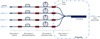 |
Fig. 1 Overview of the GRAVITY chain of single-mode waveguides. The light coming from the telescopes is injected in the Fiber Coupler fibers inside the cryostat of GRAVTY (first section). Each fiber is then connected to a FDDL (Sect. 2) and to a Fibered Polarization Rotator (Sect. 3). The light is then fed to the V-groove fibers connected to the integrated optics beam combiner (Sect. 4 inside the dash-dotted line box). All work at cold temperatures (240 K for the first three sections and 200 K for the integrated optics beam combiner part). This figure was first presented in Perraut et al. (2018). |
2 Layout and top-level requirements
The principles of the GRAVITY instrument are presented in GRAVITY Collaboration (2017). GRAVITY primarily uses single-mode fibers to filter residual aberrations in order to achieve the high-precision interferometry described in Sect. 1. The instrument has two output channels: the Science Channel and the Fringe Tracker channel. These two channels can either be fed with two sources, a reference source for the Fringe Tracker and a science source for the Science Channel, or by a single source, that is, the science source, which then serves as both a reference and science source; in that case the light is split in the Fiber Coupler. In the former case, the GRAVITY metrology provides the difference in optical path between the two fringe pattern systems, while in the latter case the GRAVITY metrology can only be used to control moving parts in the beam such as the FDDLs (Sect. 4). GRAVITY therefore has a total of eight interfering beams: two channels for each of the four telescopes. Each of these beams follows exactly the same design as sketched out in Fig. 1. Light coming from the four VLTI delay lines is focused at the entrance of the GRAVITY cryogenic vessel in the Fiber Coupler, which splits the light to feed the four injection fibers of each channel. Each fiber is connected to a FDDL (Sect. 4) linked to an FPR (Sect. 5). The set of FDDLs and FPRs is called the Fiber Control Unit (FCU), which is used to control path lengths and polarization rotation. The FCU is then connected to the V-groove fibers feeding the integrated optics beam combiners. All connections are performed with E2000 connectors from Diamond whose specification is to ensure 0.1 dB connections of telecom fibers.
Requirements were set on the subsystems, on the fibers (high throughput, weak birefringence, and low differential dispersion), and on the connections to achieve high sensitivity (fringe tracking at least on a K = 10 source, a coherent magnitude of K = 11 has been achieved, Lacour et al. 2019), high accuracy (1% on visibility amplitudes, 0.1° on closure phases, and 10 µas on astrometry), and high reliability under low pressure and cryogenic temperatures.
The VLTI is equipped with large stroke delay lines in a 130 m tunnel that can compensate for the variations in optical path length that are of sidereal origin (Glindemann et al. 2001). The action of the delay lines cancels the path-length differences for a fixed point in the field but cannot compensate for path-length differences between the two targets of GRAVITY. The purpose of the FDDLs is to compensate for the residual differences, which can be as large as 6 mm for two targets at low elevation separated by 6 arcsec and with a differential velocity of up to 150 nm s−1 with the 200 m maximum baseline of the VLTI using the ATs. We note that this stroke is not enough for the GRAVITY wide mode of GRAVITY+, and an additional system is required to compensate differential delays in this mode (GRAVITY+ Collaboration 2022). Another purpose of the FDDLs is to offset the bias in optical path difference (OPD) between the fibers after minimizing differential dispersion (see Sects. 3.3 and 4). In addition, the FDDLs need to be stable enough to get negligible OPD noise during long integrations compared to other sources, with the goal being to reach 1 nm over 100 s exposures.
Because of the use of weakly birefringent standard fibers, the differential angles between the polarizations of the GRAVITY beams need to be zeroed before injection into the integrated optics chips. The requirement on the FPRs is to align the polarization axes with an accuracy of better than 8° in order to reach contrasts of 99% or higher. Although they are motorized, the FPRs are not used to dynamically compensate for polarization rotations in both GRAVITY and VLTI but to make GRAVITY polarization neutral. In addition, the user has the option to split and analyze polarizations with a half-wave plate downstream from the beam combiners in the spectrometers in order to measure the Stokes parameters and perform interfero-polarimetry.
Three series of four FPRs and four FDDLs have been produced and labelled ABCD, EFGH, and IJKL. The last batch is a spare, while the first two are used in the GRAVITY instrument. ABCD are used in the Fringe Tracker channels, while EFGH are used in the Science channels. The IJKL spares have been individually characterized, but the performance (differential dispersion and throughput) of the full chain with the IJKL FDDLs and FPRs cannot be given as they have not been connected to the Fiber Coupler and V-groove fibers.
The performance of the fibers and FCU and the specific performance of the FDDLs and FPRs are given in Table 1. Some characteristics of the fibers and of the FCU were already presented in GRAVITY Collaboration (2017) and Perraut et al. (2018). These are updated and discussed in more detail in the following sections.
3 Characteristics of the fibers
The fibers for GRAVITY were developed by the Le Verre Fluoré company in France. The class of ZBLAN glasses was discovered by Poulain et al. (1975) with promising transmission properties in the infrared. The fibers used for GRAVITY are a type of ZBLAN mostly made of zirconium (ZrF4).
The main function of the fibers is to transport light across the instrument with minimum losses. For single-mode interferometry, another function is to filter the beams to get rid of the variations of phase due to turbulence across individual pupils. Doing so, the phase fluctuations are traded against intensity fluctuations, which are measured and calibrated out following the principles introduced for the FLUOR instrument (Coudé du Foresto et al. 1997). In the case of GRAVITY, the so-called photometric signals – which measure the quantity of photons coupled in each fiber – are extracted from the 24 outputs of the beam combiner by linear combination.
Apart from the light pollution issue experienced with the metrology laser (Sect. 3.5), no major difficulty was experienced when using the fibers at 240 K, even when stretching and twisting them to build optical delay (Sect. 4) and to rotate polarizations (Sect. 5).
Main characteristics of the fibers and Fiber Control Unit elements of GRAVITY.
3.1 Waveguide parameters
The guiding property of the fibers is obtained by slightly changing the composition of the core with respect to the cladding to get a higher index of refraction ncore compared to nclad. The fundamental mode and the number of modes carried by a step-index fiber with constant refractive indices in the core and the cladding are determined by three parameters: the numerical aperture  , the radius of the core a, and the wavelength λ; the radius of the cladding is supposed to be infinite. The fiber is single-mode for wavelengths λ larger than the cut-off wavelength
  (Neumann 1988). For K-band instruments in general, the aim is to set λc just below 2 µm by adjusting the other two parameters NA and a. Light is mostly guided in the core close to the cut-off wavelength but an increasing amount of light gets guided in the cladding with increasing wavelength, causing losses if the fibers are bent. In the case of GRAVITY, the fibers also transport the metrology laser at 1.908 nm (Rabien et al. 2008; Lippa et al. 2016) and need to be single-mode at this wavelength. Given that a large fraction of the fiber lengths are wrapped around spools in the FDDLs (15.9–17.5 m out of total lengths of 20.5 to 22 m), we chose a cut-off wavelength as close as possible to 1.908 nm and the fibers were therefore specified to be single-mode just below the metrology wavelength in order to minimize losses at the upper end of the K band. The fundamental mode is not a Gaussian for step-index fibers (it is a Gaussian if the index law is Gaussian across the fiber) but is a combination of Bessel functions. However, it is relatively close to a Gaussian beam and a waist is defined, the value of which is approximately:
  , with
  being the normalized frequency (Neumann 1988). The f/D ratio of the focusing optics is optimized to reach optimum injection in the fiber in the absence of aberrations. The maximum coupling efficiency for a uniform and full circular pupil is 78% (Shaklan & Roddier 1988). The waist varies almost linearly with the wavelength, which means that the injection efficiency is almost flat across the K band. NA and a are chosen so that an aberration-free focusing optics can be easily produced. Together with the constraints to be fulfilled to produce fibers of excellent quality, this led to the choice of NA = 0.22 and 2a = 6.55 µm at 2 µm (meaning f/D ≃ 3 for the focusing optics) as shown in Table 1. With these values, the cut-off wavelength reaches 1.88 and 1.9 µm for the two batches of fibers used for GRAVITY. This was confirmed by measuring the fiber throughput for increasing curvature radius, which set the cut-off wavelength at 1.9 µm.
3.2 Birefringence
The GRAVITY fibers were specified to be at most weakly birefringent in order to allow operation without splitting polarizations while reaching high fringe contrasts. The aim here is to achieve maximum sensitivity when working with faint sources and to perform astrometry between two sources with optimum accuracy. The effect of birefringence between the two axes of polarization can be characterized by measuring the generalized Malus law of the delay lines and the FPRs of Sect. 5 with the setup explained in Appendix A. The intensity for various positions of the polarizer and of the analyzer between 0 and 180° is plotted in Fig. 2.
Assuming orthogonal neutral axes can be defined for the fiber and aligned with the 0 or 90° positions of the polarizer, following Eq. (A.7), the normalized intensity (by the maximum detected intensity) measured at the output of the analyzer can be written as:
 (1)
(1)
where θP is the angle of the polarizer, θA is the angle of the analyzer, and δφ is the amount of differential birefringence phase between the two axes of polarization. The effect of birefringence is to reduce the amplitude depending on the angle of the polarizer in the input. There is no effect for a polarization aligned with the neutral axes of the fibers, that is, for  , and the effect is maximum for a polarization rotated by 45°(90°), that is, for
  . The envelope of the family of generalized Malus laws is no longer flat, as shown in Fig. B.1. This effect shows up in Fig. 2 where the envelope is plotted with the black dashed lines. This figure is compatible with the existence of neutral axes for the fiber, which in this case are aligned with the 0 and 90° positions of the polarizer. Equation (B.4) gives the expressions of the upper and lower envelopes:
 (2)
(2)
These expressions depend on the single parameter δφ and provide a method to measure the effect of birefringence. In the presence of birefringence, the maximum of the minimum is no longer zero and the minimum of the maximum is no longer 1, but these are respectively  and
and  , assuming that
  , that is, for a length of fiber equal to less than one-quarter of the birefringence length with a maximum modulation of the Malus laws in this particular case. The difference between the propagation constants of the two polarization axes can be written as:
 (3)
(3)
where LB is the beating length of birefringence. The accumulated differential phases between the two polarizations over a length of fiber L can be written as:
 (4)
(4)
and therefore for a given fiber length L, the beating length of birefringence can be deduced from the measurement of δφ, as:
 (5)
(5)
The measurement of the birefringence characteristics of the fibers at 240 K using the method presented in this paper is given in Table 2. The beat length of birefringence was measured between 297 m and 1110 m for the GRAVITY fibers. Fringe contrasts of interferograms are degraded by the difference in differential birefringence phase ∆δφ between the beams as they are multiplied by  (see e.g., Rousselet-Perraut et al. 1996). As the orientations of the neutral axes of the fibers have not been controlled in GRAVITY, the worst case for the fringe contrast is obtained when the differential phases are large, have opposite signs, and add up in the above formula as ∆δφ = |δφ1| + |δφ2|, leading to the minimum contrasts given in the last column of Table 2. The lowest possible contrast of 93. 1% is achieved for the A–D baseline of the Fringe Tracker, while this value is systematically larger than 97.4% for the Science Channel and larger than 96.9% for the Spare. An average value between the minimum and maximum contrasts is probably more representative of the performance of GRAVITY in practice, which sets typical contrast losses due to birefringence to less than 5% for the combination of the FDDLs and FPRs, which is our initial specification. Taking into account the extra lengths of 2 m of the Fiber Coupler and of the V-groove fibers connecting to the Integrated Optics chips to extrapolate fringe contrasts, ∆δφ needs to be increased by 10%, which reduces the minimum possible contrast to 92% for the Fringe Tracker and to 97% for the Science Channel with probable values of the order 95% or more, in practice. In addition, no clear variation of birefringence was measured during the tests when changing the FDDL extension or the FPR angle.
Birefringence measurements of the GRAVITY fibers at 240 K.
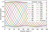 |
Fig. 2 Example of generalized Malus laws for 18 orientations of the polarizer upstream from the injection in a chain of fibers made of FDDL A, FPR A, and the A fiber coupler (total length of 18.88 m), and 18 orientations of the analyzer downstream with the setup of Fig. A.1. The dashed line is the envelope of Eq. (B.1) with a measured birefringence phase difference between the two polarization axes of 20°, yielding a birefringence beating length of 339 m according to the method presented in Appendix B. |
3.3 Differential dispersion
Differential dispersion is taken here to mean the accumulated difference of the second-order variation of the phase of the wave as a function of wavenumber between two fibers caused by the propagation in the fibers. Namely, ϕ″(σ) if the interferogram measured by GRAVITY writes A + B cos (2πσx + ϕ(σ)), where x is the OPD. The differential dispersion term is measured in units of µrad cm2.
The effect of fiber dispersion is to spread the interferogram over the OPD. More specifically, the effect of the first derivative of the phase is to shift the interferogram by  and the second-order derivative yields an OPD shift as a function of wavenumber. As a consequence, interferograms at different wavelengths will not contribute to the maximum-contrast white-light fringe at the same OPD, therefore reducing contrast in wide band. The other consequence is that measuring the fringe phase, which contains the intrinsic visibility phase information, requires a calibration.
Intrinsic fiber dispersion cannot be canceled but differential dispersion can be minimized. Differential dispersion has several components: material dispersion due to the dependance of refractive index on wavelength, waveguide dispersion due to the dependance of the mode on wavelength, and profile dispersion due to the variation of refractive index along the fiber (Coudé du Foresto et al. 1995). In addition, geometric irregularities along the fiber also add a dispersion term. The first two terms dominate and have opposite signs. Differential dispersion is classically compensated by increasing the fiber length of one arm relative to the other in the two-arm interferometer at the expense of optical-path equalization, which is achieved with the FDDLs in the case of GRAVITY. The differential dispersion of the ‘OHANA fluoride glass-fiber cables was minimized by combining six sections of 50 m fibers with compensating effects (Kotani et al. 2005; Perrin et al. 2006). The same technique has been applied for GRAVITY. The dispersion of each element of GRAVITY (fiber couplers, FDDLs, FPRs, and fiber bundles to the integrated optics chips) has been measured against a common reference in a Mach-Zehnder interferometer at Le Verre Fluoré, which was developed with LESIA in the 1990s. A fused-fluoride glass-fiber coupler was used as a beam combiner for accurate and repeatable dispersion measurements. The various fiber components of GRAVITY were then assembled to minimize both path length and dispersion differences, which reached a maximum of 2.17 mm in pathlength (B–C baseline of the FT channel) and 2.04 µrad cm2 (E-F baseline of the SC channel), respectively, at zero extension for the FDDLs, which corresponds to a contrast loss of less than 1% for the low-spectral-resolution mode of GRAVITY (λ/δλ ≃ 22), and negligible contrast losses at medium and high spectral resolutions. This amount of dispersion would be equivalently produced by 14 m of air in the VLTI tunnel using the model for the refractivity of air of Colavita et al. (2004).
The values for each fiber chain are given in Table 3. Differential dispersion varies with the extension of FDDLs as shown in Fig. 6 by approximately 1 µrad cm2 per millimeter of OPD generated by the FDDLs (equivalent to 7 m of air dispersion per millimeter). In the most extreme case, where one FDDL remains at zero while another reaches the maximum stroke of 6 mm, the maximum differential dispersion reaches 8.75 µrad cm2 (this is the case between beams E and H for example in the Science Channel) leading to an absolute fringe contrast of 94.2%. However, this requires a source at the edge of the field at the lowest elevation and in the direction of the longest baseline with the ATs and is therefore very unlikely. In any case, this loss of 5.8% fringe contrast would not prevent fringe tracking compared to a situation with more than 99% fringe contrast, and the loss of contrast in the science channel at such low spectral resolution (no noticeable loss of contrast for spectral resolutions of 500 and 4000) would be easily calibrated on an unresolved target. The effect of dispersion can therefore be considered close to negligible on fringe contrast. Fiber dispersion needs to be calibrated for astrometry with GRAVITY. This is part of the calibration plan. The issue is minimized by using a metrology with a wavelength of 1.908 µm very close to the K band and by measuring the dispersion of the fibers as a function of OPD every month.
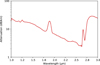 |
Fig. 3 Attenuation of the fiber of the second batch measured by the cutback method. The peak at 1.9 µm is due to the leakage of high-order modes as the fiber becomes single mode. |
Differential dispersion and length characteristics of the GRAVITY fiber chains at 240 K and for zero extension of the FDDLs.
Throughput of the GRAVITY fiber chains. Each chain comprises the Fiber Coupler fiber, an FDDL, an FPR, and a V-groove fiber.
3.4 Throughput
The throughput of the fiber chains is determined by several factors; first of all, by the intrinsic transparency of fluoride glass fibers. The attenuation by the fibers used for GRAVITY is shown in Fig. 3 as measured with the cut-back method on the last batch of fibers produced for GRAVITY. The attenuation increases towards the blue because of Rayleigh scattering and increases after 2.3 µm because of absorption by water. The attenuation has a local peak at 1.9 µm because of the suppression of high-order modes as the fiber becomes single mode. The attenuation is 6.63 dB km−1 at 2 µm and 3.65 dB km−1 at 2.4 µm, yielding transmissions of respectively 97% and 98% for 20 m of fiber.
Connections are another possible source of transmission loss. Photons are lost at each of the three connections (Fig. 1) between the Fiber Coupler fiber, the FDDL, the FPR, and the V-groove fiber. Part of the loss is due to Fresnel reflection at the air-glass interface, while another part is due to the misalignment of fiber cores. We used E2000 PC connectors from Diamond to minimize both effects. The two fiber ends are held in contact with each other in the adapter to minimize Fresnel losses. The fibers are held in a ceramic ferrule encapsulated in a soft metal jacket. The soft metal jacket allows the core-to-core alignment between paired fiber ends to be adjusted very accurately. An accuracy of 1 µm is reached with maximum losses of 0.05 to 0.1 dB per connection or a total additional loss of 3.4% to 6.7% per fiber chain.
The third potential main factor is the bending of the fibers in the FDDLs. Losses are all the more important as the wavelength is large as the wave is less confined in the core of the fiber. A first theory was put forward by Marcuse (1976a) assuming infinite radius for the cladding. A more realistic approach has been proposed to account for the limited radius of the cladding (Faustini & Martini 1997), even with metallic claddings (Peng et al. 2017). The bend loss in dBs for a given curvature radius R and length of bend L can be written (adapted from e.g., Peng et al. 2017):
![Mathematical equation: ${L_{\rm{s}}} = 10{\log _{10}}\left[ {\exp \left( {2\alpha a{L \over a}} \right)} \right],$](/articles/aa/full_html/2024/01/aa47587-23/aa47587-23-eq17.png) (6)
(6)
where a is the radius of the fiber core and 2α is the bend-loss factor. Marcuse (1976b) computed 2αα as a function of the normalized radius of curvature R/α for a single-mode fiber at the cutoff frequency for values ranging between 300 and 5000. The exponential law can be extrapolated to R/a = 6154 in the case of the GRAVITY fibers yielding a bend loss of 6 × 10⁻²⁸ dB for 10 m of bend length, which is a completely negligible loss. Although the mode is 25% larger at the upper edge of the K band at 2.4 µm, the same conclusion applies at this wavelength.
In conclusion, the losses are in practice dominated by the connections and this is most certainly what the results of Table 4 show with a minimum throughput of 87.5% and an average throughput of 90%, which is excellent given the number of functions performed by the fibers: namely beam transport, polarization control, differential delays, and feeding of the beam combiners.
3.5 Raman scattering and fluorescence
GRAVITY uses a 1 W laser at 1908 nm to measure the OPDs between the science and reference beams in each of the four telescopes. The principles of the metrology system are described in Lippa et al. (2016). A small fraction (less than 1%) of the laser light is injected backwards from the two beam combination points and is propagated upward to the telescope entrance pupils to have a full measurement of the OPDs between the science and reference beams in all four telescopes. The highpower fraction (more than 99%) of the laser beam is overlaid with the faint fraction at the entrance of the fiber couplers where the beams coming from the telescopes are fed into the fibers. This three-beam scheme was chosen to minimize the amount of power injected into the single-mode waveguides of GRAVITY. In the initial setup, only the laser beams going through the beam combiners were used, hence with full power going through the fibers. This led to high levels of light back-scattered into the GRAVITY spectrometers because of two distinctive effects that produce additional photon noise in the K band. These effects are described in Lippa et al. (2018). One is Raman scattering, which is the consequence of the interaction between a photon and a phonon. In one configuration of the interaction, a laser photon loses energy to a phonon and is shifted to a wavelength of around 2150 nm in the K band. The other effect is fluorescence of the rare earth elements holmium (Ho3+) and thulium (Tm3+), which are used to produce doped fibers. The GRAVITY fibers were contaminated at the ppm level by these elements, which is enough to produce faint signals in the K band up to 2100 nm by excitation of the holmium ions with the very bright metrology laser. The combination of the two effects leads to contamination of the blue part of the K band up to 2200 nm (see Fig. 4 of Lippa et al. 2018). A second batch of fibers was produced with reduced contamination, which allowed minimization of the contamination by fluorescence but had no effect on the Raman scattering part. The three-beam scheme allows the effects to be mitigated, with the remaining backscattering still being slightly larger than the thermal background, but only by a factor of a few and only for a few pixels at the shortest wavelengths in the detector band.
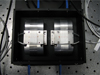 |
Fig. 4 Pair of GRAVITY FDDLs. Four blue fiber jackets are visible at the top and bottom of the box. The fibers are wrapped on two half cylinders, one fixed and one mounted on a piezo actuator. Delay is produced by stretching the fibers with the piezos. The gray and white cables on the left and right are the power and gauge sensor cables of the piezos. |
4 Fibered differential delay lines
GRAVITY has a moderate need for differential delay compensation. The maximum differential delay is for the use of the ATs for which a maximum baseline of 200 m can be reached. The distance between the science and reference targets of 6 arcsec is also maximum with the ATs. The two combined lead to a maximum delay of 6 mm and a maximum differential speed of the zero OPD of 150 nm s−1 at the lowest elevation. Such static and dynamic delays can be obtained by stretching fibers. All GRAVITY beams are equipped with FDDLs and the maximum differential delay between the reference and the science targets is consequently twice the stroke of the FDDLs. A stroke of 3 mm per FDDL would therefore be sufficient. However, the minimization of differential dispersion between slightly inhomogeneous fibers leads to differential lengths, which need to be compensated for. We therefore set a goal to reach 6 mm maximum stroke for each FDDL in order to have some margin. The first attempts at fibered delay lines were made by the IRCOM/XLIM group at Université de Limoges in the 1990s with silica fibers. The technique was used to produce a linear optical path modulation, first with a moderate stroke of 20 λ at an accuracy of λ/200 (λ = 633 nm) with a laser control system (Reynaud & Delaire 1993). Zhao et al. (1994) then developed a fibered Mach-Zehnder interferometer at Paris Observatory with standard fluoride-glass fibers, whose optical path was scanned with a fiber wrapped on a piezo cylinder. The stretching of curved fibers introduces birefringence and differential dispersion, both of which have been analyzed (Zhao et al. 1995a,b). All these lead to moderate delays of a few thousand λ at most. Simohamed et al. (1996) demonstrated a 318 mm stroke with 20 m of stretched polarization maintaining fibers. Fibers were positioned in 90° V-grooves with an isotropic distribution of stress in the fiber core in order to minimize induced birefringence. Simohamed & Reynaud (1997) reached a 2 m stroke with 100 m of fibers wrapped on an expanding cylinder.
The relative stretch of a 125 µm fluoride glass was measured to be 0.1% or 2 µm/(mm N), which therefore allows us to generate several millimeters of delay with sufficient fiber length and sufficient force applied to the fiber. Given the stringent accuracy requirements of GRAVITY, the challenges in building the delay lines were related to the throughput, in particular the potential losses due to the curvature of fibers in the spools, the control accuracy, the birefringence, and the second-order phase dispersion variations as a function of stretch. The characteristics of the FDDLs are listed in Table 1 and an example of pair of FDDLs is presented in Fig. 4.
The issue of throughput and curvature radius for the spools is addressed in Sect. 3.4. With a 4 cm spool diameter, no significant loss is to be expected.
The high sensitivity of fibers to mechanical and thermal stresses is a characteristic exploited to build sensors with fiber optics and this sensitivity to physical conditions is an issue when using them for outdoor interferometry, as in aperture synthesis arrays. Fibered delay lines were for example used in ‘OHANA primarily as dispersion compensators as the lengths of the fibers were not controlled with a metrology system and suffered from temperature fluctuations along the 300 m of fiber length (Vergnole et al. 2004; Kotani et al. 2005). Following a first experiment by Connes & Reynaud (1988), Reynaud et al. (1992) then showed how to stabilize silica fiber lengths with a laser metrology in order to build a fiber interferometer. A similar technique is used for GRAVITY. To fulfill the specifications on path-length accuracy and time response, the delay lines were designed as two-stage devices: the fibers are wrapped on half-cylinders whose relative distances are actuated by translation stages with servo controlled piezo stacks (modified P-611.1S translation stages from Physik Instrument with 100 µm stroke; the control of the piezos is operated with an E-621 controller, the piezo length being measured with a strain gauge sensor) and the overall path-length stability is controlled by the GRAVITY metrology coupled with the GRAVITY piston actuators. This second stage is necessary because of the intrinsic hysteresis of the spools of fibers wrapped around the half cylinders. The motion of the piezo is mechanically amplified by a pantograph whose elasticity is constrained by the loops of fibers. The effect of the expansion of the piezo applied to the pantograph is therefore not linear because of the resistance of the fibers, and the final stroke of the FDDLs is not as large as what is theoretically attainable with the piezo stacks. The control electronics of the FDDLs were designed to ensure that the error of FDDL commands have negligible impact on both fringe contrast and OPD error measurement for typical integration times of several minutes. This requires at least 18-bit precision. For 6 mm of range this translates to a precision of 40 nm per FDDL. For long exposure fringes this translates to visibilities of 99% and for OPD measurements to accuracies of 0.6 nm. We designed a real-time controller providing 20-bit precision commands (6 nm precision on a 6 mm range) so that the final performance of our architecture is limited by the performance of the Physik Instrument amplifier. The amplifier has an internal noise of 800 µV and requires 18-bit coding to keep the command noise to 460 µV for a voltage of between 0 and 120 V (some measurements by PI showed down to 100 µV or 20-bit precision noise in closed loop). In addition, the amplifier has a 100 kHz bandpass, which is far beyond the requirements for GRAVITY given the very slow differential speed between two channels.
The half cylinders were manufactured with perfectly smooth surfaces and without any grooves. The fibers were wrapped on the half cylinders with a constant tension provided by a 25 g weight attached to a fiber end to generate a tension of 0.25 N. The wrapping was performed without any torsion of the fiber in order to minimize constraints. As a result, the measured birefringence is very low (see Sect. 3.2) and no noticeable variation of birefringence with FDDL extension has been measured. Examples of optical path length generation by FDDLs as a function of piezo extension or of voltage applied to the piezo are shown in Fig. 5, with a maximum delay of 6 mm. The E–L delay lines are shown here, while a total of 12 have been produced and labelled A to L. The A–D and E–H were produced first and the I–L were produced later as spares, the difference with the 8 first delay lines being essentially the lowest contamination of the fibers by holmium and thulium. The minimum stroke of 5.7 mm obtained for the F or L delay lines leaves a sufficient margin with which to compensate the maximum bias in OPD of 2.29 mm between beams F and G (Table 3).
Figure 6 shows the amount of second-order dispersion generated by stretching the delay lines of Fig. 5. The second-order dispersion varies for the two batches of FDDLs by approximately 1 μrad cm2 per mm of generated delay. This additional dispersion reduces the fringe contrast by 5.8% in the most extreme case with a dispersion of R ≃ 22 in the K band, as seen in Sect. 3.3. In practice, this has a negligible effect on the capability of GRAVITY to fringe track and can be easily calibrated.
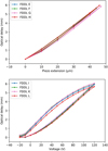 |
Fig. 5 Examples of optical path-length laws for two batches of Fibered Differential Delay Lines (FDDL). FDDL E, F, G, H were built with the first generation of GRAVITY fibers while I, J, K, L were built with the second generation of GRAVITY fibers. An optical delay of up to 6 mm is built in both cases. The command is the piezo extension for E, F, G, H while it is a voltage for I, J, K, L to show the amount of hysteresis corrected by the Physik Instrument E-621 servo controller. |
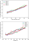 |
Fig. 6 Examples of second-order differential dispersion laws for the two sets EFGH and IJKL of FDDLs. The average dispersion was set to zero at minimum FDDL extension. Both sets of delay lines generate a maximum of 5 µrad cm2 at a maximum extension of 6 mm. Abscissas are as in Fig. 5. |
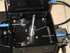 |
Fig. 7 GRAVITY flbered polarization rotator. The blue jackets are the fiber output and input. The loop of fiber goes through a hole at the top of the shaft, which defines the rotation axis. The rotation of the shaft is controlled by a stepper motor. The two mechanical end switches are visible at the bottom of the box. The torsion applied to the fiber by the rotation of the shaft generates a rotation of the polarization of the beam going through the fiber. |
5 Fibered polarization rotators
We made the choice to not use polarization-maintaining fibers for GRAVITY, but to use weak birefringence fibers instead, allowing us to avoid systematic splitting of polarizations and therefore to optimize sensitivity and ensure that GRAVITY is as polarization neutral as possible. The prerequisite is the very low birefringence of the fluoride-glass fibers, which was demonstrated with the very demanding ’OHANA project following the achievements with FLUOR and measured in the case of the GRAVITY fibers (Sect. 3.2). As the GRAVITY fibers do not maintain polarizations, the axes of linearly polarized radiation can rotate after propagation in the fibers. For weakly birefringent fibers, polarization neutrality can only be achieved if the differential orientation of the axes of polarization can be canceled. The traditional way to align polarization axes in fibers is to use Lefèvre loops (Lefèvre 1980). The basic principle of the device is to induce birefringence in the fibers through stress by bending the fibers. The device is equivalent to wave plates that allow polarizations in the fibers to be controlled. Such devices have been used for FLUOR in a simplified version with two loops only in two perpendicular planes to rotate polarizations without introducing birefringence, as it was found that birefringence was not the primary cause of contrast loss in interferometers with standard fluoride-glass fibers (Perrin et al. 1998). The system was further simplified by Le Verre Fluoré, who later showed that a single loop was sufficient. Such a simplified version was used for FLUOR, VINCI (Kervella et al. 2000), and ’OHANA (Perrin et al. 2006). This is the basis of the system used for GRAVITY, which is described in this section.
The principle of the GRAVITY FPR is quite simple: a torsion is applied to a loop of fiber across a diameter in order to rotate polarizations. The curvature radius is sufficiently large to avoid losses and birefringence induced by stress. An example of FPR is presented in Fig. 7. A shaft is actuated by a stepper motor to twist the fiber along the vertical axis. The fiber is loose in the hole at the top of the shaft and at the input and output feedthroughs. End switches allow the twist range to be controlled in order to avoid damaging the fiber.
The actuator is a Phytron stepper motor VSS-UHVC 25.200.0.3 compatible with the temperature of operation. The torque required to twist the fiber loop is 0.035 mN m, while the stepper motor yields a 12 mN m torque. The stepper motors are driven by a Programmable Logic Controller from Beckhoff. Motion commands are sent in units of micro-steps: eight micro-steps per real motor step. One full motor revolution is accomplished in 200 steps so that a full revolution requires 1600 micro-steps. This provides ample resolution to accurately rotate the polarization by 0.25° per micro-step. The motor is turned off when not in use by setting the hold current to zero to avoid heating in vacuum and errors due to fluctuating power. The FPRs lie in a horizontal plane so that no mechanical motion can be set by gravitation.
The performance of the FPRs was measured at 240 K. Malus laws were measured by injecting linearly polarized light into the FPRs and detecting the rotated polarization with an analyzer at the output. Examples of resulting Malus laws are presented in Fig. 8. The rotation angle versus motor step command laws can be easily deduced from the Malus laws and are presented in the same figure. From these, the goal is achieved with an amplitude of rotation of larger than 180°. The amplitude could still be increased by moving the end switches slightly. The rotations are reproducible with an accuracy of the order of 1° or better (8° is necessary to reach 99% fringe contrast). In practice, the FPRs are used to align the linearly polarized light of an internal calibration source (GRAVITY Collaboration 2023) which ensures a high level of visibility contrast on sky (GRAVITY Collaboration 2017). The FPRs are not operated during the observation nights and remain at fixed positions.
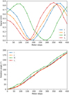 |
Fig. 8 Examples of Malus laws (top) and angle laws (bottom) for the fibered polarization rotators IJKL. The angle has been arbitrarily set to 0° for 0 motor steps. |
6 Conclusions
The interest in single-mode fibers for high-precision interferometry has become firmly established since the concept was introduced in the early 1980s. Later developments showed that fibers are also efficient for beam transportation. In this paper, we present the characteristics of the single-mode fibers and associated functions designed for the very demanding GRAVITY instrument. Very weakly birefringent standard fibers are used to maximize both the sensitivity of the instrument and the accuracy of astrometric measurements. Fibers are stretched in the FDDLs to compensate for differential delays of up to 6 mm between the fringe patterns in the two fields of GRAVITY. Fibers are twisted in the FPRs to align polarizations between the GRAVITY arms, with the possibility to compensate for up to 180° of differential rotation in order to maximize fringe contrast. The typical contrast losses due to differential birefringence are of the order of 5% while the contrast losses due to differential second-order dispersion are less than 1% in the lowest spectral resolution mode of GRAVITY. These latter would reach a maximum of less than 6% in the extreme case of a science source at the edge of the theoretical field of view of 6″ on the longest baseline of the VLTI with the ATs and at the lowest elevation possible. The contrast losses would be completely negligible with the medium- and high-resolution modes in the science channel. In addition to the fantastic coherence and polarimetric performance of the GRAVITY fibers, the throughput for the 20.5–22 m chains is very high and ranges between 87.5% and 92.9%, with connection losses included. Overall, the performance of the GRAVITY fibers and their functions meet the desired specifications or exceed them. There is no equivalent of this fiber system with which to route and modally filter beams – with delay and polarization control – in any other K-band beamcombiner.
Acknowledgements
GRAVITY has been developed in a collaboration by the Max Planck Institute for Extraterrestrial Physics, LESIA of Paris Observatory-PSL/CNRS/Sorbonne Université/Université Paris-Cité and IPAG of Université Grenoble Alpes/CNRS, the Max Planck Institute for Astronomy, the University of Cologne, the Centro Multidisciplinar de Astrofisica Lisbon and Porto, and the European Southern Observatory. The Fiber Control Unit has been developed and procured thanks to the funding support of CNRS/INSU (CSAA and ASHRA).
Appendix A Generalized Malus law
The geometry and notations of the setup to measure the Malus law along the axis of the fiber are given in Fig. A.1. The wave used to analyze the properties of the fibers is described by a complex vector  . It propagates along the axis
  . Here,
  is written at a given distance ɀ:
 (A.1)
(A.1)
For an unpolarized wave,  . For a polarized wave,
![Mathematical equation: $\left[ {\matrix{ {{E_x}} \hfill \cr {{E_y}} \hfill \cr } } \right] = {E_p}\left[ {\matrix{ {\cos \psi {e^{ - i{\varphi _x}}}} \hfill \cr {\sin \psi {e^{ - i{\varphi _y}}}} \hfill \cr } } \right],$](/articles/aa/full_html/2024/01/aa47587-23/aa47587-23-eq23.png) (A.2)
(A.2)
with  .
.
Here, θp is the orientation of the polarizer axis with respect to  counted positively towards
  . Let us now assume that the fiber is birefringent with
  and
and  , which are the neutral axes of the fiber, with
  being the amount of birefringence phase accumulated along
  on the
  axis and
  being the amount of birefringence phase accumulated on the
  axis (time has been shifted to have opposite amounts of birefringent phase on the x and y axes).
After the polarizer, the wave is projected on the axis of the polarizer  and is written as:
 (A.3)
(A.3)
The wave is then injected into the fiber and propagates down to the analyzer (we assume the coupling to the fiber is lossless). The wave accumulates birefringent phases on the x and y axes. At the fiber output, this can be written as:
 (A.4)
(A.4)
The wave is filtered at the output of the fiber with an analyzer rotated by an angle θA with respect to the  axis. The effect of the analyzer is to project the incoming wave in the direction
  , giving the analyzed wave:
 (A.5)
(A.5)
The average intensity detected at the output of the analyzer is independent of ɀ and t and is written as:
 (A.6)
(A.6)
The first term takes different values depending on the nature of the input wave; for an unpolarized wave, it is equal to  , while for a polarized wave it is equal to Ip cos2 (ψ − θP). This is the classical Malus law. Developing and reorganizing the second term, for the intensity one obtains:
![Mathematical equation: $\matrix{ {\,\,\,\,\,\,{I_A}\left( {{\theta _{\rm{A}}},{\theta _{\rm{P}}},\delta \varphi } \right) = \,} \hfill \cr {\left\{ {\matrix{ {{1 \over 2}{I_{np}}\left[ {{{\cos }^2}\left( {{\theta _{\rm{A}}} - {\theta _{\rm{P}}}} \right) - {{\sin }^2}\left( {{{\delta \varphi } \over 2}} \right)\sin \left( {2{\theta _{\rm{A}}}} \right)\sin \left( {2{\theta _{\rm{P}}}} \right)} \right]} \hfill \cr {{I_p}{{\cos }^2}\left( {\psi - {\theta _{\rm{P}}}} \right)\left[ {{{\cos }^2}\left( {{\theta _{\rm{A}}} - {\theta _{\rm{P}}}} \right) - {{\sin }^2}\left( {{{\delta \varphi } \over 2}} \right)\sin \left( {2{\theta _{\rm{A}}}} \right)\sin \left( {2{\theta _{\rm{P}}}} \right)} \right],} \hfill \cr } } \right.} \hfill \cr } $](/articles/aa/full_html/2024/01/aa47587-23/aa47587-23-eq42.png) (A.7)
(A.7)
where the first line is the unpolarized case and the second one is the polarized case. The cosine term in the square parentheses is the classical Malus law for polarized light and the second term is the effect of birefringence. We note that in the case of polarized light, there is a cascade of two Malus laws as the light filtered by the two polarizers is already polarized in the input.
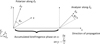 |
Fig. A.1 Setup used to measure the generalized Malus laws of a flbered device as a function of input linear polarizer angle θP and output analyzer angle θA. |
Appendix B Measurement of birefringence
We show in Appendix A that the classical expression of the Malus law needs to be modified to account for birefringence. Conversely, it can be used to measure the birefringence properties of the fiber. Natural light is used to measure the properties of the GRAVITY fibers. In the following, we therefore consider the first line of Eq. A.7 for unpolarized light. It is a family of curves with parameters either θA or θP with θP or θA being the respective variable. We show here that the characteristics of the envelope of this family depend on the birefringence phase δφ.
In the following, we consider θP as the parameter and θA as the variable. We highlight the fact that Eq. A.7 is symmetric and therefore either case can be chosen. The expression of the envelope of the curves is classically deduced by expressing that it both takes generalized Malus law values and is tangent to the curves. It amounts to solving the system of equations:
 (B.1)
(B.1)
by eliminating θP and getting the expression of Ienv The system of equations is easier to solve by rewriting Eq A.7 as the real part of a complex number:
![Mathematical equation: $\matrix{ {{I_A}\left( {{\theta _{\rm{A}}},{\theta _{\rm{P}}},\delta \varphi } \right) = {{{I_{np}}} \over 4} \times {\mathop{\rm Re}\nolimits} \left[ {{{\cos }^2}\left( {{{\delta \varphi } \over 2}} \right)\left[ {1 + {e^{2i\left( {{\theta _{\rm{A}}} - {\theta _{\rm{p}}}} \right)}}} \right]} \right.} \cr {\,\,\,\,\,\,\,\,\,\,\,\,\,\,\,\,\,\,\,\,\,\,\,\,\,\,\,\,\,\,\,\,\,\,\,\,\,\,\,\,\,\,\,\,\,\,\,\,\, + \left. {{{\sin }^2}\left( {{{\delta \varphi } \over 2}} \right)\left[ {1 + {e^{2i\left( {{\theta _{\rm{A}}} + {\theta _{\rm{P}}}} \right)}}} \right]} \right].} \cr } $](/articles/aa/full_html/2024/01/aa47587-23/aa47587-23-eq44.png) (B.2)
(B.2)
Defining cA = cos(2θA), sA = sin(2θA), cP = cos(2θP), sP = sin(2θP),  , and
, and  the above system can be written in matricial form as:
![Mathematical equation: $\left[ {\matrix{ {{{4{I_{{\rm{env}}}} - {I_{np}}} \over {{I_{np}}}}} \cr 0 \cr } } \right] = \left[ {\matrix{ {{c_A}} & {{s_A}\cos \varphi } \cr {{s_A}\cos \varphi } & { - {c_A}} \cr } } \right]\left[ {\matrix{ {{c_P}} \hfill \cr {{s_P}} \hfill \cr } } \right],$](/articles/aa/full_html/2024/01/aa47587-23/aa47587-23-eq47.png) (B.3)
(B.3)
and can be solved for cP and sP. The matrix cannot be inverted if  and
and  , in which case
  . Otherwise the system can be inverted, yielding values for cP and sP leading to a quadratic equation by expressing:
  . The quadratic equation has two solutions in the general case leading to upper and lower envelopes:
 (B.4)
(B.4)
These expressions depend on the birefringence phase δφ and provide a method to measure it Some examples for various birefringence differential phases are plotted in Fig B.1. In the particular case of δφ = 0(π), Ilow and Iup are constant, and are equal to 0 and 1, respectively. In the absence of birefringence, the generalized Malus laws systematically reach the maximum amplitude and in the case where the fiber length is a multiple of half of the beat length of birefringence, birefringence has no effect on the generalized Malus law. When birefringence is small, as in the case of the GRAVITY fibers, a modulation of the envelope of the generalized Malus laws is therefore a sign of birefringence, and can be used to measure it and predict its effects on the measurements made with GRAVITY.
References
- Anugu, N., Le Bouquin, J.-B., Monnier, J. D., et al. 2020, AJ, 160, 158 [NASA ADS] [CrossRef] [Google Scholar]
- Colavita, M. M., Swain, M. R., Akeson, R. L., Koresko, C. D., & Hill, R. J. 2004, RASP, 116, 876 [CrossRef] [Google Scholar]
- Connes, P., & Reynaud, F. 1988, in European Southern Observatory Conference and Workshop Proceedings, 29, 1117 [NASA ADS] [Google Scholar]
- Coudé du Foresto, V., & Ridgway, S. T. 1992, in European Southern Observatory Conference and Workshop Proceedings, 39, 731 [Google Scholar]
- Coudé du Foresto, V., Perrin, G., & Boccas, M. 1995, A&A, 293, 278 [NASA ADS] [Google Scholar]
- Coudé du Foresto, V., Ridgway, S., & Mariotti, J. M. 1997, A&AS, 121, 379 [NASA ADS] [CrossRef] [EDP Sciences] [Google Scholar]
- Faustini, L., & Martini, G. 1997, J. Lightwave Technol., 15, 671 [NASA ADS] [CrossRef] [Google Scholar]
- Froehly, C. 1981, in Scientific Importance of High Angular Resolution at Infrared and Optical Wavelengths, 285 [Google Scholar]
- Gardner, T., Monnier, J. D., Fekel, F. C., et al. 2021, AJ, 161, 40 [NASA ADS] [CrossRef] [Google Scholar]
- Glindemann, A., Bauvir, B., van Boekel, R., et al. 2001, in Liège International Astrophysical Colloquia, 36, eds. J. Surdej, J. P. Swings, D. Caro, & A. Detal, 27 [Google Scholar]
- GRAVITY Collaboration (Abuter, R., et al.) 2017, A&A, 602, A94 [NASA ADS] [CrossRef] [EDP Sciences] [Google Scholar]
- GRAVITY+ Collaboration (Abuter, R., et al.) 2022, A&A, 665, A75 [NASA ADS] [CrossRef] [EDP Sciences] [Google Scholar]
- GRAVITY Collaboration (Widmann, F., et al.) 2023, A&A, in press, https://doi.org/10.1051/0004-6361/202347238 [Google Scholar]
- Kervella, P., Coudé du Foresto, V., Glindemann, A., & Hofmann, R. 2000, SPIE Conf. Ser., 4006, 31 [NASA ADS] [Google Scholar]
- Kotani, T., Perrin, G., Vergnole, S., Woillez, J., & Guerin, J. 2005, Appl. Opt., 44, 5029 [NASA ADS] [CrossRef] [Google Scholar]
- Lacour, S., Dembet, R., Abuter, R., et al. 2019, A&A, 624, A99 [NASA ADS] [CrossRef] [EDP Sciences] [Google Scholar]
- Lazareff, B., Le Bouquin, J. B., & Berger, J. P. 2012, A&A, 543, A31 [NASA ADS] [CrossRef] [EDP Sciences] [Google Scholar]
- Le Bouquin, J. B., Berger, J. P., Lazareff, B., et al. 2011, A&A, 535, A67 [NASA ADS] [CrossRef] [EDP Sciences] [Google Scholar]
- Lefèvre, H. C. 1980, Electron. Lett., 16, 778 [CrossRef] [Google Scholar]
- Lippa, M., Gillessen, S., Blind, N., et al. 2016, SPIE Conf. Ser., 9907, 990722 [NASA ADS] [Google Scholar]
- Lippa, M., Gillessen, S., Blind, N., et al. 2018, SPIE Conf. Ser., 10701, 107011Y [NASA ADS] [Google Scholar]
- Marcuse, D. 1976a, J. Opt. Soc. Am., 66, 216 [NASA ADS] [CrossRef] [Google Scholar]
- Marcuse, D. 1976b, J. Opt. Soc. Am., 66, 311 [NASA ADS] [CrossRef] [Google Scholar]
- Mourard, D., Berio, P., Pannetier, C., et al. 2022, SPIE Conf. Ser., 12183, 1218308 [NASA ADS] [Google Scholar]
- Neumann, E.-G. 1988, Single-mode fibers (Germany: Springer Berlin, Heidelberg) [CrossRef] [Google Scholar]
- Peng, X., Cha, Y., Zhang, H., Li, Y., & Ye, J. 2017, Opt. Eng., 56, 066102 [CrossRef] [Google Scholar]
- Perraut, K., Jocou, L., Berger, J. P., et al. 2018, A&A, 614, A70 [NASA ADS] [CrossRef] [EDP Sciences] [Google Scholar]
- Perrin, G., Coudé du Foresto, V., Ridgway, S. T., et al. 1998, A&A, 331, 619 [NASA ADS] [Google Scholar]
- Perrin, G., Woillez, J., Lai, O., et al. 2006, Science, 311, 194 [NASA ADS] [CrossRef] [Google Scholar]
- Poulain, M., Poulain, M., & Lucas, J. 1975, Mater. Res. Bull., 10, 243 [CrossRef] [Google Scholar]
- Rabien, S., Gillessen, S., Ziegleder, J., et al. 2008, in Optical and Infrared Interferometry, 7013, eds. M. Schöller, W. C. Danchi, & F. Delplancke, International Society for Optics and Photonics (SPIE), 70130I [CrossRef] [Google Scholar]
- Reynaud, F., & Delaire, E. 1993, Electron. Lett., 29, 1718 [NASA ADS] [CrossRef] [Google Scholar]
- Reynaud, F., Alleman, J. J., & Connes, P. 1992, Appl. Opt., 31, 3736 [NASA ADS] [CrossRef] [Google Scholar]
- Rousselet-Perraut, K., Vakili, F., & Mourard, D. 1996, Opt. Eng., 35, 2943 [CrossRef] [Google Scholar]
- Setterholm, B. R., Monnier, J. D., Bouquin, J.-B. L., et al. 2023, J. Astron. Telescopes Instrum. Syst., 9, 025006 [NASA ADS] [Google Scholar]
- Shaklan, S. B., & Roddier, F. 1987, Appl. Opt., 26, 2159 [NASA ADS] [CrossRef] [Google Scholar]
- Shaklan, S., & Roddier, F. 1988, Appl. Opt., 27, 2334 [NASA ADS] [CrossRef] [Google Scholar]
- Simohamed, L. M., & Reynaud, F. 1997, Pure Appl. Opt., 6, L37 [NASA ADS] [CrossRef] [Google Scholar]
- Simohamed, L. M., Delage, L., & Reynaud, F. 1996, Pure Appl. Opt., 5, 1005 [NASA ADS] [CrossRef] [Google Scholar]
- Tamura, Y., Sakuma, H., Morita, K., et al. 2018, J. Lightwave Technol., 36, 44 [NASA ADS] [CrossRef] [Google Scholar]
- Vergnole, S., Delage, L., & Reynaud, F. 2004, Opt. Commun., 232, 31 [CrossRef] [Google Scholar]
- Zhao, P., Mariotti, J. M., Léna, P., Coudé du Foresto, V., & Zhou, B. 1994, Opt. Commun., 110, 497 [CrossRef] [Google Scholar]
- Zhao, P., Mariotti, J.-M., Foresto, V. C. D., Léna, P., & Reynaud, F. 1995a, J. Mod. Opt., 42, 2533 [NASA ADS] [CrossRef] [Google Scholar]
- Zhao, P., Mariotti, J. M., Léna, P., Coudé du Foresto, V., & Mazé, G. 1995b, Appl. Opt., 34, 4200 [NASA ADS] [CrossRef] [Google Scholar]
All Tables
Differential dispersion and length characteristics of the GRAVITY fiber chains at 240 K and for zero extension of the FDDLs.
Throughput of the GRAVITY fiber chains. Each chain comprises the Fiber Coupler fiber, an FDDL, an FPR, and a V-groove fiber.
All Figures
|
Fig. 1 Overview of the GRAVITY chain of single-mode waveguides. The light coming from the telescopes is injected in the Fiber Coupler fibers inside the cryostat of GRAVTY (first section). Each fiber is then connected to a FDDL (Sect. 2) and to a Fibered Polarization Rotator (Sect. 3). The light is then fed to the V-groove fibers connected to the integrated optics beam combiner (Sect. 4 inside the dash-dotted line box). All work at cold temperatures (240 K for the first three sections and 200 K for the integrated optics beam combiner part). This figure was first presented in Perraut et al. (2018). |
| In the text | |
|
Fig. 2 Example of generalized Malus laws for 18 orientations of the polarizer upstream from the injection in a chain of fibers made of FDDL A, FPR A, and the A fiber coupler (total length of 18.88 m), and 18 orientations of the analyzer downstream with the setup of Fig. A.1. The dashed line is the envelope of Eq. (B.1) with a measured birefringence phase difference between the two polarization axes of 20°, yielding a birefringence beating length of 339 m according to the method presented in Appendix B. |
| In the text | |
|
Fig. 3 Attenuation of the fiber of the second batch measured by the cutback method. The peak at 1.9 µm is due to the leakage of high-order modes as the fiber becomes single mode. |
| In the text | |
|
Fig. 4 Pair of GRAVITY FDDLs. Four blue fiber jackets are visible at the top and bottom of the box. The fibers are wrapped on two half cylinders, one fixed and one mounted on a piezo actuator. Delay is produced by stretching the fibers with the piezos. The gray and white cables on the left and right are the power and gauge sensor cables of the piezos. |
| In the text | |
|
Fig. 5 Examples of optical path-length laws for two batches of Fibered Differential Delay Lines (FDDL). FDDL E, F, G, H were built with the first generation of GRAVITY fibers while I, J, K, L were built with the second generation of GRAVITY fibers. An optical delay of up to 6 mm is built in both cases. The command is the piezo extension for E, F, G, H while it is a voltage for I, J, K, L to show the amount of hysteresis corrected by the Physik Instrument E-621 servo controller. |
| In the text | |
|
Fig. 6 Examples of second-order differential dispersion laws for the two sets EFGH and IJKL of FDDLs. The average dispersion was set to zero at minimum FDDL extension. Both sets of delay lines generate a maximum of 5 µrad cm2 at a maximum extension of 6 mm. Abscissas are as in Fig. 5. |
| In the text | |
|
Fig. 7 GRAVITY flbered polarization rotator. The blue jackets are the fiber output and input. The loop of fiber goes through a hole at the top of the shaft, which defines the rotation axis. The rotation of the shaft is controlled by a stepper motor. The two mechanical end switches are visible at the bottom of the box. The torsion applied to the fiber by the rotation of the shaft generates a rotation of the polarization of the beam going through the fiber. |
| In the text | |
|
Fig. 8 Examples of Malus laws (top) and angle laws (bottom) for the fibered polarization rotators IJKL. The angle has been arbitrarily set to 0° for 0 motor steps. |
| In the text | |
|
Fig. A.1 Setup used to measure the generalized Malus laws of a flbered device as a function of input linear polarizer angle θP and output analyzer angle θA. |
| In the text | |
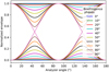 |
Fig. B.1 Envelopes of the Malus laws given by Eq. B.4 for various birefringence differential phases. |
| In the text | |
Current usage metrics show cumulative count of Article Views (full-text article views including HTML views, PDF and ePub downloads, according to the available data) and Abstracts Views on Vision4Press platform.
Data correspond to usage on the plateform after 2015. The current usage metrics is available 48-96 hours after online publication and is updated daily on week days.
Initial download of the metrics may take a while.