| Issue |
A&A
Volume 668, December 2022
|
|
|---|---|---|
| Article Number | A129 | |
| Number of page(s) | 19 | |
| Section | Astronomical instrumentation | |
| DOI | https://doi.org/10.1051/0004-6361/202244123 | |
| Published online | 15 December 2022 | |
Multi-frame blind deconvolution and phase diversity with statistical inclusion of uncorrected high-order modes
Institute for Solar Physics, Department of Astronomy, Stockholm University, Albanova University Center,
106 91
Stockholm, Sweden
e-mail: This email address is being protected from spambots. You need JavaScript enabled to view it.
Received:
26
May
2022
Accepted:
17
October
2022
Abstract
Context. Images collected with ground-based telescopes suffer blurring and distortions from turbulence in the Earth’s atmosphere. Adaptive optics (AO) can only partially compensate for these effects. Neither multi-frame blind deconvolution (MFBD) methods nor speckle techniques perfectly restore AO-compensated images to the correct power spectrum and contrast. MFBD methods can only estimate and compensate for a finite number of low-order aberrations, leaving a tail of uncorrected high-order modes. Restoration of AO-corrected data with speckle interferometry depends on calibrations of the AO corrections together with assumptions regarding the height distribution of atmospheric turbulence.
Aims. We seek to develop an improvement to MFBD image restoration that combines the use of turbulence statistics to account for high-order modes in speckle interferometry with the ability of MFBD methods to sense low-order modes that can be partially corrected by AO and/or include fixed or slowly changing instrumental aberrations.
Methods. We modify the MFBD image-formation model by supplementing the fitted low-order wavefront aberrations with tails of random high-order aberrations. These tails follow Kolmogorov statistics scaled to estimated or measured values of Fried’s parameter, r0, that characterize the strength of the seeing at the moment of data collection. We refer to this as statistical diversity (SD). We test the implementation of MFBD with SD with noise-free synthetic data, simulating many different values of r0 and numbers of modes corrected with AO.
Results. Statistical diversity improves the contrasts and power spectra of restored images, both in accuracy and in consistency with varying r0, without penalty in processing time. Together with focus diversity (FD, or traditional phase diversity), the results are almost perfect. SD also reduces errors in the fitted wavefront parameters. MFBD with SD and FD seems to be resistant to errors of several percentage in the assumed r0 values.
Conclusions. The addition of SD to MFBD methods shows great promise for improving contrasts and power spectra in restored images. Further studies with real data are merited.
Key words: methods: numerical / techniques: high angular resolution / techniques: image processing
© M. G. Löfdahl and T. Hillberg 2022
 Open Access article, published by EDP Sciences, under the terms of the Creative Commons Attribution License (https://creativecommons.org/licenses/by/4.0), which permits unrestricted use, distribution, and reproduction in any medium, provided the original work is properly cited.
This article is published in open access under the Subscribe-to-Open model. This email address is being protected from spambots. You need JavaScript enabled to view it. to support open access publication.
1 Introduction
Astronomical images from ground-based telescopes are degraded by random wavefront aberrations caused by turbulence in the Earth’s atmosphere. For high-resolution solar observations, a combination of adaptive optics (AO) and image restoration has been very successful in delivering image data collected in good seeing with resolution near the diffraction limit of the telescope. However, it has proved harder to restore images to the correct power spectrum and contrast.
Gonsalves & Chidlaw (1979) introduced phase diversity (PD) as a way to constrain the problem of retrieving the wave-front phase from image plane data. Paxman et al. (1992a) derived the model fitting rigorously for different noise models and extended the formalism to multiple diversities. PD is based on images recorded with a (preferably known) difference in the wavefront phase, most often a parabola corresponding to a slight defocus of one or more cameras. Paxman et al. (1992b) combined PD with multi-frame blind deconvolution (MFBD; Schulz 1993) and referred to this as phase-diverse speckle interferometry (PDS). MFBD methods (including PD and PDS) in the present context are based on fitting a model of the spaceinvariant image formation process to the data, where both the wavefront aberrations over the pupil and (at least formally) the image pixel intensities are the fitted parameters. Löfdahl & Scharmer (1994) and Seldin & Paxman (1994) independently developed PDS for high-resolution solar images. These developments form the core of the methods (Löfdahl 2002; van Noort et al. 2005; Löfdahl et al. 2021) used during two decades for restoration of image data from the Swedish 1m Solar Telescope (SST; Scharmer et al. 2003a). The space-invariant model is only valid within an isoplanatic patch with a size on the order of only a few arcseconds. Because of this, the restoration is usually performed in 4–5″ squared subfields where the assumption of space invariance is approximately true. This size is a trade-off between the smaller isoplanatic patch and the need for subfields of sufficient size to contain the necessary fine structure. A restored version of a larger field of view (FOV) is formed by mosaicking the restored subfields.
Solar PD- and MFBD-based image restoration can restore good data to diffraction-limited resolution. This is very useful for science based on the spatial shapes of features in the photosphere and tracking motions. Examples of this include motions and shapes of magnetic elements (e.g. Berger et al. 1998, 2004), formation of micropores (Berger et al. 2002), spatial structure and magnetic field in sunspot penumbrae (Scharmer et al. 2002, 2008; Langhans et al. 2005; Spruit et al. 2010), and faculae as hot-wall granulation (Carlsson et al. 2004). During the last decade, SST observations have been based on the CRISP (Scharmer et al. 2008) and CHROMIS (Scharmer 2017) spectro(polari)meters, where narrowband (NB) data are collected in short bursts of approximately ten frames per wavelength tuning and polarization state, and synchronized wideband (WB) data are collected throughout the line scan. Such data are usually processed with multi-object MFBD (MOMFBD; van Noort et al. 2005; Löfdahl 2002), where the WB data constrain the aberrations identified for the individual NB states and restored images are calculated for all NB states as well as for the WB. Physical quantities at multiple heights in the photosphere and chromosphere are then fit by inverting models of the solar atmosphere with codes such as those of Socas-Navarro et al. (2015), de la Cruz Rodríguez et al. (2019), and de la Cruz Rodríguez (2019). This makes better control over stray light even more important. Examples of such science are studies by Vissers et al. (2019), Esteban Pozuelo et al. (2019), Rouppe van der Voort et al. (2021), and Morosin et al. (2022).
However, the contrasts and power spectra of AO-corrected observations that are processed with MFBD-based methods have not been reliably restored. Comparisons based on synthetic data, with objects from magnetohydrodynamic (MHD) simulations and aberrations following Kolmogorov statistics, reveal that observed data were lacking in contrast. Scharmer et al. (2010) found that high-order wavefront aberrations uncorrected by AO and image restoration was a significant cause. Löfdahl & Scharmer (2012) investigated conventional large-angle stray light in the instrumentation and found that it was a minor cause after an adjustment of the position of the AO wavefront sensor (WFS). Löfdahl (2016) measured light scattered by the atmosphere with very wide point spread functions (PSFs) and found that this was also not a main reason for the low contrast. Recently, Scharmer et al. (2019) reported on the optical performance of the SST after an upgrade of the AO system and some other optics. The conclusion from these investigations, as well as from analysis by Scharmer et al. (2011, supporting material) using the intensity in sunspot umbrae as a constraint, is that the remaining stray light comes from a PSF that is not wider than a few arcseconds and that high-order modes not corrected by AO or image restoration are one of the major causes of the missing contrast. The resulting PSF wings are a well-known effect known in night-time astronomy as a diffuse halo around stellar objects.
Scharmer et al. (2010) proposed a method for compensating for the uncorrected high-order modes with a post-restoration deconvolution. The corrective PSF was calculated from random high-order wavefronts following the correct statistics. This compensation worked in the ideal case, where all Karhunen–Loève (KL; e.g., Roddier 1990) modes up to a certain cutoff were perfectly corrected by AO and/or image restoration. For such data, the contrast after compensation for the high-order modes is consistent for varying r0. However, there is no perfect cutoff in the modes corrected by MFBD. MFBD partially “compensates” for the effect of uncorrected high-order modes by introducing errors in the modes included in the MFBD model. Therefore, the post-restoration deconvolution led to an over-compensation of the contrast after MFBD processing with the number of wavefront parameters typically used.
Saranathan et al. (2021) built on the work by Scharmer et al. (2010) by introducing the efficiencies with which the AO corrects the individual KL modes. Saranathan et al. simulated wavefronts with Kolmogorov statistics with the r0 reported by the AO WFS, degraded synthetic images from MHD simulations based on the corresponding transfer functions, and then used MFBD on both the real data and the synthetic data. The ratios of the standard deviations of the mode amplitudes in the two restorations yield the efficiencies of the AO for all modes. The corresponding contributions are subtracted from the synthetic wavefronts, allowing a straylight PSF to be constructed with the efficiencies taken into account. As in the method by Scharmer et al. (2010), data can be deconvolved with this PSF post-restoration. One drawback with this method is that the parallel MFBD processing has to be done with all KL modes that are involved in the AO correction; in the SST case, this means at least the ~230 KL modes used for modeling the AO modes (they included 250 modes). Further assumptions are that the MFBD restoration is perfect up to some number of modes and that the MFBD processing with 250 modes works similarly well for the real data and for the synthetic data. Saranathan et al. (2021) report on the processing of a single dataset collected at 630 nm while r0 on average was 13 cm, increasing the restored contrast from 9% to 12.3%, closer to the contrast expected from MHD simulations but still 2.5–3 percentage points lower. With only a single dataset, the consistency of the restored contrast for datasets collected in different seeing conditions remains unclear. Also, the reported contrast is in the center of the FOV where the correction works best. For consistent correction outside the center of the FOV, the time-consuming calculation of the efficiencies would have to be run at several distances from the WFS FOV.
Paxman et al. (1996) restored 470 nm solar granulation data from the Swedish Vacuum Solar Telescope (SVST; Scharmer et al. 1985) with PDS as well as speckle interferometry (simply referred to as Speckle hereafter), and compared the results. While the restored images were virtually identical in appearance and resolution, the Speckle restorations had significantly more power and RMS contrast (12.6% for Speckle vs. 11.0% for PDS). Paxman et al. (1996) found that a plausible explanation was that the lower contrast for PDS was caused by the low-order parameterization of the wavefronts, with only 15 Zernike polynomials (Noll 1976).
Methods based on Speckle (Labeyrie 1970) differ from MFBD methods in that they are not based on a necessarily finite parameterization of the wavefront; they independently reconstruct the Fourier phases (which encode the locations of features and gradients in an image) and the Fourier amplitude (i.e., the relative weights of large and small intensity variations in the image) of the restored object. The Fourier phases are reconstructed by use of a process that is independent of the statistical properties of the wavefront. Here, we are more interested in the Fourier amplitudes, the square of which is the power spectrum. For this, the statistics of atmospheric turbulence are used to infer the appropriate speckle transfer functions (STFs), which are corrections to the Fourier amplitudes (and thereby to the power spectra and contrasts). Without AO correction, these STFs depend temporally only on Fried’s parameter, r0 (Fried 1966), which was measured with the spectral ratio method (von der Lühe 1984). The spectral ratio is the ratio of the square of a long-exposure transfer function and an average of the squares of an ensemble of short-exposure transfer functions. Assuming the object does not change, this can be calculated from a set of images that statistically sample the random turbulence in the atmosphere, usually about 100 exposures recorded during a sufficiently long time interval such that statistical averages can be considered relevant. The spatial frequency at which the spectral ratio tends to zero is a measure of r0. Like MFBD methods, Speckle is based on a space-invariant image-formation model, applied in subfields of larger FOVs. von der Lühe (1993) developed this method for solar observations into the Kiepenheuer Institut Speckle Imaging Package (KISIP).
There are several other Speckle codes that are or have been used for restoration of solar images. We do not attempt a full account here, but mention a few developments that lead up to the Speckle restoration used for DKIST data (Beard et al. 2020), as we believe this should be state of the art in 2022.
The implementation of AO on major high-resolution solar telescopes (see Rimmele & Marino 2011, for an account of the history) posed a challenge for Speckle. AO compensation has no impact on the reconstruction of the Fourier phases, and so restoration to diffraction-limited resolution did not require any changes (e.g., Denker et al. 2005). However, the AO correction changes the statistics of the wavefront aberrations and thereby the shapes of the spectral ratios as well as the STFs. The problem is two-fold: (1) At the lock point of the AO WFS, these quantities depend not only on r0, but also on the efficiencies with which the AO can correct aberrations at different spatial scales. This means r0 cannot be measured from the spectral ratios without accounting for the AO correction and the STFs cannot be calculated from r0 alone. (2) Due to anisoplanatism, the AO correction efficiencies decline with the field angle (the distance from the WFS lock point), by varying degree depending on the spatial scales of the wavefront aberrations. (At large field angles, the wavefront can actually be degraded by the AO.) This means the STFs depend on r0, the efficiencies, and the field angle.
Molodij & Rousset (1997) developed the formalism for how Zernike polynomial components of atmospheric wavefronts decorrelate with distance in the focal plane for particular atmospheric turbulence profiles. Using this and an assumption of a two-layer atmosphere with one phase screen at the pupil and one at 10 km altitude, Wöger & von der Lühe (2007) modified the spectral ratio method to support AO correction. These authors measured the efficiencies of the AO correction at the lock point as decomposed into Zernike polynomials. With this input, they could calculate the corresponding spectral ratio and STF models as a function of r0, AO efficiency, and field angle, building a library for lookup in the reconstruction process. Using a least squares fit to find the spectral ratio model that best fits the data, both r0 and the AO correction efficiency are found for a particular data set. A metric indicating how well the predicted decorrelation of the Zernike modes matches the data is computed as a side product. The best-matched spectral-ratio model immediately provides the STF to be applied to the Fourier amplitude. Wöger et al. (2008) implemented this approach in KISIP.
Publications that report on the contrasts in AO-corrected data collected in varying conditions and restored with this implementation appear to be scarce. However, Uitenbroek et al. (2007) restored 115 min of G-band (430 nm) image data from the Dunn Solar Telescope. They measured r0 values with a distribution centered on 10.2 cm with most values between 8 and 15 cm during the collection interval. The restored granulation contrasts ranged from 7% to 14% of the average intensity, correlating with the raw data contrasts as well as with the measured r0 (their Figs. 2 and 3). Their Fig. 1 (left half) shows a restored image. The image quality shows strong variations over the FOV, with the contrast in the upper left corner being much lower than in the center and lower left.
Further developments include measuring r0 with the AO WFS instead of the spectral ratio (Wöger 2010), which reduces the number of parameters that have to be measured with the spectral ratio method. Peck et al. (2017) showed that with a good measurement of r0, the transfer functions at the AO lock point can be reliably calculated. The estimation of the transfer function at other field angles is less certain because the distribution of the turbulent layers in the atmosphere along the line of sight can change from day to day and even on a timescale of hours due to changes in elevation, and also differs between observatory sites. Monitoring this and maintaining a database of STFs for all possible turbulence profiles would be a major undertaking. How well the two-layer model with height calibration represents realistic scenarios is an open question, but this approach seems to work well most of the time (F. Wöger, priv. comm.).
Deep learning with neural networks (NNs) has seen great progress in many kinds of image processing in recent years, with MFBD of high-resolution solar image data being one of them. Asensio Ramos et al. (2018) demonstrated an extremely fast algorithm based on this latter technique. After being trained with output from the MOMFBD code (traditional MFBD, with or without PD), the MFBD NN is able to provide similar results several orders of magnitude faster. Like traditional MFBD methods, it handles anisoplanatism by restoring subfields that are subsequently mosaicked to form the restored version of a large FOV. Carlos Diaz Baso recently designed a version of this NN1, which is now installed at the SST, providing an almost real-time view of the target area during observations with a resolution that is similar to the science data delivered by the SSTRED pipeline (Löfdahl et al. 2021); it can also be used for making high-quality quick-look movies.
Wang et al. (2021) similarly trained their NN with Speckle-restored images. After training, it could output images of similar quality much faster and with the additional feature that it does not assume spatially invariant blurring, and so has the potential to handle anisoplanatism better.
Incorporating a physical model of the image formation, including wavefront phases as sums of KL modes, Asensio Ramos & Olspert (2021) demonstrated a promising development path to NN MFBD for scientific use. This implementation is trained with only raw data, and does not require already restored data for this step. With the training outlined by these latter authors, their NN produced restored images of inferior quality compared to traditional MFBD restorations based on the same data sets. This was apparently due to estimation of the wavefronts only succeeding for a few of the modes. However, as the authors point out, the main purpose of the paper was to provide a framework for this kind of processing and they point out several ways to improve the quality of the restorations in the future, including using more diverse data for training as well as adding support for PD data.
A relevant point here is that the method of Asensio Ramos & Olspert (2021) is based on the same image-formation model as traditional MFBD, including a finite parameterization of the wavefront phase. Therefore, when some of the issues with their demo dataset are fixed, their NN MFBD method should have the same weakness when it comes to restoring the data to correct and consistent power.
In the present paper, we propose a statistical compensation for the high-order modes that are not included in the finite parameterization of the wavefront phases in MFBD processing. In the methods developed by Scharmer et al. (2010) and Saranathan et al. (2021), this compensation was applied after the MFBD image restoration. Here, the compensation is instead included in the MFBD image-formation model itself.
To a good approximation, the fitted low-order modes are enough to model the core of the PSF, successfully restoring the structures and resolution of the real scene. The details in the less-well-determined high-order modes are of less importance, but they combine to produce extended wings of the PSFs, which affect the contrast. If any AO-corrected modes are included in the MFBD-fitted modes, the unaltered high-order components therefore only need to be corrected in a statistical sense, using a model of the atmospheric turbulence. This is similar to Speckle, except that Speckle uses the statistics for the entire wavefronts.
To implement this high-order wavefront compensation, we use the PD concept in a novel way. We introduce random but fixed contributions from the uncorrected high-order wavefront modes in a statistical sense as early as in the MFBD-based image restoration step. A fully developed method is outside the scope of this paper; here we provide a proof of concept with synthetic data. We ignore complications such as noise, anisoplanatism, or modeling of a real AO system, but demonstrate that SD has the potential to improve estimation of the PSFs and make the restored contrast consistently more correct, without significantly increasing the computing time. We also investigate the method’s sensitivity to a few different kinds of errors.
We revisit the theory of MFBD and PD in Sect. 2 as well as the method of Scharmer et al. (2010) and then go on to develop the proposed method. In Sect. 3, we describe our synthetic data, simulating the effects of atmospheric turbulence with varying strength as well as AO correction of varying numbers of modes. We demonstrate some aspects of the proposed method in Sect. 4 and discuss the results in Sect. 5. We end with some conclusions in Sect. 6.
2 Theory
2.1 Image formation
We use a space-invariant image-formation model, including additive Gaussian white noise. The optical system is characterized by a generalized pupil function, which can be written for a wavefront with number j ∈ {1,…, J} (for real data, usually equivalent to a time coordinate) and a diversity component θjk as
 (1)
(1)
where xp is the 2D spatial coordinate in the pupil plane (which we now drop for brevity in the notation), A is a binary function that encodes the geometrical shape and size of the pupil, and ϕj are the instantaneous phase variations of a wavefront emanating from the object as it reaches the pupil.
The phase of an instantaneous wavefront with index j can be expanded in suitable basis functions, {ψm}, or modes as
 (2)
(2)
We use KL modes as the basis functions {ψm}, disregarding the inconsequential piston mode. This choice corresponds to MOMFBD processing of real SST data (Löfdahl et al. 2021) and approximately to the control modes of the SST AO (Scharmer et al. 2003b, 2019) together with the correlation tracker. The KL coefficients follow normal distributions,
 (3)
(3)
where D is the telescope aperture diameter and  are the atmospheric variances of the KL modes. With correction of M modes by use of AO and/or MFBD, it is useful to write this as a part with correction, ϕjM, plus a tail of higher order uncorrected modes, τjM,
 (4)
(4)
We illustrate the splitting of a sample random realization of ϕj for a few values of M in Fig. 1. As M grows, τjM becomes flatter and loses all of its larger features. For the Strehl ratios, we use the wavefront variance after optimal modal correction with M modes, which can be written as
 (5)
(5)
(Scharmer et al. 2010; based on a figure by Roddier 1998), where D is the telescope diameter (97 cm), and the expression for the Strehl ratio SM as a function of the variance,
 (6)
(6)
We note that as M includes the tip and tilt modes, which do not affect the contrast of individual exposures, correction of M modes corresponds to correction of M − 2 modes with curvature.
With a diversity term
 (7)
(7)
we can represent PD in the form of defocus (Zernike polynomial 4) by ak radians RMS. For PD with two cameras, we often use a1 = 0 and a2 selected so that a2Z4 has a peak-to-valley (PTV) of approximately one wave. For reasons that are made apparent in Sect. 2.4, we hereafter refer to PD with defocus as “focus diversity” (FD), using PD as a more general term.
The optical transfer function (OTF), can be expressed as the auto-correlation of the pupil function,
 (8)
(8)
where 𝔉{·} denotes the Fourier transform and 𝔉−1{·} its inverse. The isoplanatic formation of an image, djk, is the convolution of an object f and the PSF sjk = 𝔉−1{Sjk}. In the Fourier domain, we can write this as
 (9)
(9)
where Njk is an additive noise term with Gaussian statistics, and u is the 2D spatial frequency coordinate. We also drop this coordinate for brevity (as well as the spatial coordinate x in the focal plane).
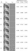 |
Fig. 1 Example of an instantaneous wavefront phase ϕj split into ϕjM, a sum of the first M modes, and τjM, the residual tail of higher-order modes; see Eq. (4). The Strehl ratios are calculated for r0 = 6, 10, and 15 cm (corresponding to 1″.7, 1″.0, and 0″.5 seeing, respectively) with Eqs. (5) and (6), assuming a 97cm aperture and perfect compensation of ϕjM. The wavefront images are calculated with an upper limit of M = 1002; see Msim in Sect. 3.1 for comparison. |
2.2 Multi-frame blind deconvolution
For a derivation of the MFBD algorithm used, along with PD, we refer the reader to Löfdahl (2002) or van Noort et al. (2005). Information of various forms about the circumstances under which the data were collected, such as multiple cameras, multiple objects, and multiple PDs, can be brought to bear on the model-fitting problem by specifying linear equality constraints and using them to reduce the number of free parameters. Here we give a brief account, with the notation needed to understand PD and the novel way in which we use the concept and for the interpretation of the results.
By fitting the image formation model to the data, we can estimate low-order representations of the wavefronts,  , given by Eq. (4) and estimates of the MMFBD first wavefront coefficients. We use the circumflex,
  , to indicate quantities that are estimated (or based on other estimated quantities) by minimizing a maximum-likelihood metric that is valid for additive Gaussian noise,
 (10)
(10)
where sums over j and k should be understood as running over whatever combinations of those indices exist in the dataset. The estimated data frame can be written as
 (11)
(11)
through Eqs. (1) and (8). The pixel intensities of the object f are formally unknowns in the model but the additive Gaussian noise assumption allows us to write the estimate of the deconvolved object as
 (12)
(12)
where the superscript asterisk denotes complex conjugation and H is a low-pass filter; for example, the optimal low-pass filter of Löfdahl & Scharmer (1994).
Equation (12) can then be plugged into Eq. (11) to form an expression for  without explicit reference to the unknown object F. This eliminates
  also in the error metric of Eq. (10) and makes {αjm} the only explicit model parameters, which reduces the size of the problem significantly.
We note that in Eq. (10) we introduce a mismatch between the observational data and the image formation model in that the atmospheric wavefront aberrations of the real data, Djk, are a sum of an infinite number of modes, ϕj, while that of  is only a sum of MMFBD modes,
  . The difference is the tail of uncorrected modes,
  .
.
A dataset for MFBD with FD (also called PDS) is illustrated in Fig. 2. The fitting of the model to the data is constrained by the fact that all images depict the same object, and also by the pairwise identical wavefront ϕj with a fixed FD addition, θjk. MFBD without FD is illustrated by the same figure but without the lighter blue frames.
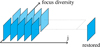 |
Fig. 2 Schematic representation of constraints and diversities for a dataset with five atmospheric wavefronts and FD. |
2.3 Post-restoration correction
Scharmer et al. (2010) proposed a method to compensate for stray light resulting from  . Their approach was to use the low-order correction with MFBD and then compensate the restored image for the average effect of hundreds of versions of
  , where we use a tilde,
  , to indicate that these are random realizations of
  , based on KL coefficients according to Eq. (3). The r0 needed in Eq. (3) was measured with a WFS. Scharmer et al. (2010) wrote the compensated object estimate in the Fourier domain as
 (13)
(13)
where the division with Ŝ is a deconvolution with a transfer function corresponding to the effect of the high-order modes. This transfer function can be written as
 (14)
(14)
where Ŝjk is calculated from the estimated  while Sjk is calculated from
  plus the random
  . The angular brackets, 〈·〉, indicate an ensemble average over many independent realizations of
  . The transfer function § removes the effect of the MFBD restoration and replaces it with a correction for both the MFBD-estimated low-order wavefront component and an average high-order component based on statistics.
The main problem with this method is that MFBD correction does not lead to a clean separation between the included low-order modes and the uncorrected high-order modes. Instead, because of the model mismatch mentioned above, the algorithm introduces errors in the MMFBD included modes to try to compensate the OTFs for the effects of the missing high-order modes.
2.4 Statistical diversity
Scharmer et al. (2010) showed that the exact realizations of the high-order components of the random wavefronts do not change the degraded images significantly, as long as they follow the correct statistics. As the MFBD error metric in Eq. (10) involves the differences between real images and synthetic images based on the estimated wavefront, this insensitivity makes it hard for MFBD to correctly identify the high-order aberrations.
We now introduce a statistical compensation for  in the MFBD model. For each estimated wavefront in a dataset, we add
  as a statistical diversity (SD) wavefront contribution, where we again use a tilde to indicate that it is based on random KL coefficients according to Eq. (3). The SD contribution reduces the model mismatch in the error metric (see Sect. 2.2) and thereby allows the low-order coefficients to converge to values that take the high-order tails into account. Instead of averaging the effects of multiple high-order random wavefronts like Scharmer et al. (2010), we here automatically get a similar effect from the individual wavefronts of the multiple images in a dataset, provided the set is large enough.
The PD contribution to each wavefront in Eq. (1) now becomes a combination of FD and SD,
 (15)
(15)
The constraints and diversity scheme is illustrated in Fig. 3. As in Fig. 2, all frames include the same object. Also, frames with the same j index share the same unknown aberrations and, depending on k, may have different FDs. In contrast to the FD terms, the SDs are independent random realizations for the different j indices.
3 Making synthetic data
We used IDL2 code to simulate the image formation of a telescope with a circular aperture of 97cm diameter with no central obscuration (like the SST).
3.1 Wavefronts
When making synthetic data for our simulation experiments, we have to limit the second sum of Eq. (4) at some point, Msim. For the work presented here, we chose to use 1000 modes with curvature, which corresponds to the approximation Msim = 1002 ≈ ∞ with the tip-tilt coefficients set to zero. We note that the truncation at Msim = 1002 modes causes a loss of Strehl ratio (see Fig. 1) but for our purposes it should be insignificant compared to the Strehls for M ≤ 102. With Msim ≫ MAO, we believe this gives us enough of a tail of uncorrected modes to reproduce the problem expected with real data.
We simulated 100 wavefronts by drawing 1000 KL coefficients per wavefront from a normal distribution N(0,σm) and scaling them to different r0 values by multiplication with (D/r0)5/6 (equivalent to Eq. (3)), where r0 ∈ {6, 8, 10, 12, 15, 20, 100} cm. The 50% AO correction was simulated by multiplying the MAO first modes with 0.5 for 50% correction, with MAO ∈ {22, 32, 42, 52, 62, 82, 102}. We also made simulated data with no AO correction.
The pupils and modes were generated with DLMs from the same code base that generates the modes used in Redux (see Sect. 4.5). This ensures consistency in making and processing the data.
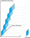 |
Fig. 3 Schematic representation of constraints and diversities for the same data as in Fig. 2 but processed with both FD and SD. |
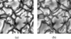 |
Fig. 4 Synthetic “true” images, (a) 538 nm. (b) 630 nm. |
3.2 Image data
The “true” 253×253-pixel images (see Fig. 4) correspond to a FOV of 6000 km (or 8″.2) squared with an image scale of 0″.0323/pixel. They are 538 and 630 nm snapshots from the same MHD simulation that Scharmer et al. (2010) used but sampled at different time coordinates.
The simulated “raw” image data were calculated by convolving the “true” images with PSFs corresponding to ϕj for the different MAO and r0 values simulated. The wavefronts were used to make PSFs at nominal focus as well as for a FD with a PTV of one wave. In addition to synthetic granulation images, we stored the PSFs to be used as point-source data. We did not include noise or anisoplanatism in the simulations.
We wanted oversize images to minimize wrap-around errors with wide PSF wings, and also to not have the same size for deconvolutions as for convolutions. The “true” images are periodic, and so we repeated the FOV in both directions and cropped to a size with small prime factors for efficient FFT operations. We then cropped further before saving images to FITS files. The MFBD image size was even smaller. The relevant sizes are summarized in Table 1. Because the “true” FOV is an odd number of pixels, we added one row and column when calculating power spectra.
We processed both 538 nm and 630 nm images for the initial experiment (Sect. 4.1), but as the results were almost identical, in the following we process only 538 nm data. We show and discuss only 538 nm data here and in the following sections, except when explicitly stating otherwise.
The contrasts of these synthetic “raw” 50% AO-corrected conventional focus images are shown in Fig. 5a for varying numbers of AO-corrected modes. We note the r0 = 100 cm images approximately reach the dotted line that represents the contrast of the true image convolved with the diffraction-limited PSF (the PSF of the theoretical 97 cm aperture without aberrations).
Deconvolution of these data with PSFs based on only the low-order parts of the wavefronts,  , does not restore the full contrast except for the r0 = 100 cm data, as shown in Fig. 5b. We also made FD data with a PTV of one wave. Sample images (first wavefront) are shown in Fig. 6. These images illustrate the fact that the information about the wavefronts manifests itself much more clearly some distance from focus than in the focal plane.
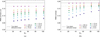 |
Fig. 5 Contrasts for synthetic 538 nm granulation data. (a) With 50% AO correction of the MAO most significant KL modes. The error bars denote the standard deviation in each set of images. (b) Multiframe-deconvolved with the correct values of the coefficients for the MAO most significant KL modes, leaving |

Image sizes.
4 Processing and results
4.1 Synthetic data with constant r0
4.1.1 Contrast and error metric
We MFBD-processed the 50% AO-corrected granulation and point source data, with and without FD as well as with and without SD. Adaptive optics is not capable of completely correcting all the MAO modes, and so we need MMFBD ≥ MAO to give MFBD the chance to provide total correction of a known number of modes. This is necessary for the statistical correction of the higher order modes to work properly. In general, MMFBD > MAO gave poorer results than MMFBD = MAO, and the granulation contrast grows seemingly without limit above that of the “true” image. We tried MMFBD = 202, 302, 402, 502, and 602. This could probably be addressed with a regularization term in the error metric, penalizing large variation in the wavefront phase. However, using MMFBD = MAO seems appropriate, and so we base the remainder of this paper on that.
In the same way that we limit figures to only 538 nm data, we show results only for subsets of the r0 and MAO datasets generated and processed. Showing results for all combinations of r0 and MAO leads to figures that are too many or too cluttered, or both. However, we inspected all the output and the subsets shown are representative of the entirety of the results.
MFBD processing the synthetic data yields contrasts shown in Fig. 7. The contrasts are enhanced compared to deconvolution with the correct low-order coefficients (compare Fig. 5b), in particular with larger r0 and with fewer modes corrected by AO and included in the fit (MAO = MMFBD). This enhancement is particularly strong without FD (open symbols). However, FD (filled symbols), while constraining the solutions and thereby reducing the contrast enhancement, does not remove it completely.
Scharmer et al. (2010) did post-restoration compensation for the uncorrected tail of high-order modes,  , (see also Sect. 2.3) but only for MFBD without FD. Our results with that method are shown in Fig. 8. Like for Scharmer et al. (2010), our data compensated in the same way have too much contrast for MFBD without FD. This is expected due to the overcompensation relative to the number of included modes mentioned in the previous paragraph. Only in the best seeing conditions is the contrast almost correct. The 6cm contrasts are too over-corrected to even fit in the plot window. Post-correcting data restored with FD gives better results but there is still mostly too much contrast, in particular with fewer modes.
Figure 9 shows the corresponding results with SD. We note that for real data we do not know the correct values of the high-order coefficients. We were therefore careful to use different random coefficients from those used when making the data.
With both FD and SD (filled symbols), the “true” contrast is recovered very well, and consistently with varying number of modes as well as varying r0. This is a very encouraging result.
Without FD (open symbols), the contrasts are too high when the number of modes is large but fairly good when the number of modes is small. With fewer modes, most of the correction is done with the fixed  contributions and when the number of fitted parameters is small, it is easier for the MFBD algorithm to converge to correct values. It is possible that the results for the larger MMFBD can be improved by regularization but this is outside the scope of this paper. We believe these results clearly demonstrate the need to collect data with FD if the SD technique is to be used.
We show MFBD-restored images in Figs. 10a (processed without FD) and 10b (with FD). The images are all scaled to the same grayscale range as the “true” image in Fig. 4 and we can see a slight dimming when smaller numbers of modes were corrected, as well as for smaller r0, in particular for data processed with FD. The apparent resolution also suffers slightly in the dimmer images, particularly for the smaller r0 (see the thinnest features in the intergranular lanes and the pointy granule in the bottom-left quadrant).
Sample images restored with SD are shown in Figs. 11a (without FD) and 11b (with FD). The improvement in the restoration of the correct contrasts is visible as less dimming and more uniform resolution.
Figures 12-14 show azimuthally averaged power spectra for restored granulation data. The drop in power at u/u0 = 0.9 (where u0 is the diffraction limit) is caused by the low-pass filter H (see Eq. (12)), which is implemented to avoid high-frequency artifacts in the restoration of real data. With no noise, this filter would extend to u0 but by default our code limits the filter to 0.9u0.
Without SD (the (a) subfigures), the power spectra are below that of the true image, and more so with smaller MAO, in particular for the smaller r0. FD generally helps, in particular in the higher spatial frequencies, but less for the smaller MAO.
Using SD leads to an overall improvement of the restored power (the (b) subfigures), in particular together with FD. Combining the two diversities (solid lines in (b)) brings the power spectra into close agreement with the true data at all spatial frequencies while SD without FD does that mostly for the lower spatial frequencies.
The over-correction of contrast without either FD or SD (dotted lines, (a) subfigures) for the smaller MAO is caused by an excess of power at low spatial frequencies. This is where most of the contrast is formed, as the square of the RMS contrast is proportional to the integral of the power.
We show that SD improves the restoration of the images but similar PSFs and OTFs can be made with quite different wave-fronts. As the MFBD model fit is evaluated by the metric L in Eq. (10) involving images and not wavefronts directly, it does not automatically follow that there is an improvement in the estimated wavefront coefficients. However, it does seem that SD improves that as well. We show median wavefront errors in the modes with curvature for the granulation data in Fig. 15 and it is apparent that they are improved significantly when both FD and SD are used, even for the smallest r0. Without FD, a more modest improvement can be seen for the smaller numbers of modes.
We also processed point source data sets with the same simulated aberrations. The wavefront errors of those are shown in Fig. 16. There are a few things to note. First, the combination of SD and FD makes granulation a better WFS than point sources with FD but without SD. With both FD and SD, the point source wavefront errors are almost zero. And when the point source data are processed with SD but without FD ((b) open symbols), for most cases the errors are as small as with FD. We discuss this further in Sect. 4.1.3
The noncurvature wavefront errors, that is, the tip-tilt components, require separate evaluation. These modes are not included when making the synthetic data; however, they are included in the parameterization of the wavefronts used in the MFBD-processing, in the same way as when we process real data. Their coefficients are allowed to change from their initial zeros, and so the estimated tip-tilt contributions are wavefront errors that correspond to shifts in the relative positions of the 100 exposures included in the data sets.
Figures 17 and 18 show the median lengths of the image shift vectors, which demonstrate that, for granulation, SD in fact improves the estimated tilts, both with and without FD. With FD, the improvements are significant, in particular for low MMFBD and r0. The tilt errors with both SD and FD are consistently small, just a few (single digits) milliarcsecs regardless of r0. The comparatively poor results without SD for low MMFBD and r0 appear to correlate with the results for the wavefront errors in Figs. 15 and 16, which is expected because we have seen before that errors in tip-tilt couple with errors in antisymmetric modes like coma, which correspond to asymmetries in the PSFs. For point sources, the results are similar, except that at larger MMFBD the shifts estimated with SD and FD are slightly larger than for SD without FD. We note that in both cases the errors are less than 2 milliarcsec.
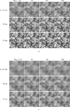 |
Fig. 6 Sample synthetic “raw” images with 50% AO correction up to mode MAO. Images degraded by first wavefront of a set of 100 random wavefronts. Grayscale as for the “true” image in Fig. 4. (a) Conventional in-focus images, (b) FD images. |
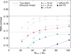 |
Fig. 7 MFBD without SD. Restored granulation contrasts. |
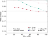 |
Fig. 8 MFBD without SD followed by post-restoration compensation for |

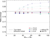 |
Fig. 9 MFBD with SD. Restored granulation contrasts. |
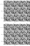 |
Fig. 10 Sample restored images using MFBD without SD. |
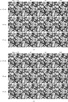 |
Fig. 11 Sample restored images using MFBD with SD. (a) Without FD. (b) With FD. |
4.1.2 Processing time and convergence
Whether or not SD comes with a penalty in processing time is a legitimate question. The number of unknowns does not increase when we add the SD, and so each iteration takes the same amount of processing (dominated by computing gradients) with or without it. The convergence depends on the optimization method used and the exact number of iterations depends on the convergence criterion used. The MOMFBD code implements multiple methods but we tend to use conjugate gradients.
Figure 19 shows the convergence of the error metric for a subset of the MMFBD and r0 datasets. We show all combinations of using or not using FD and/or SD for both granulation data and point sources. These plots, with separate curves for many datasets, do not allow detailed comparisons, but it is obvious that using SD is generally associated with faster reduction in metric than not using SD. This holds regardless of whether FD is used (panels (b) and (d)) or not (panels (a) and (c)). We note that the metric is normalized to the initial value, corresponding to zero KL coefficients. As the initial metric for the SD processing is already compensated for the high-order tails, the final differences between SD and no SD are slightly larger than shown in the figure but the effect is not dramatic.
The number of iterations seems to be smaller with SD than without, except for point sources and FD (d), but this is also where the improvement in converged error metric is the greatest.
In the other panels of Fig. 19, the improvement in error metric can be seen to be modest in many cases, which is consistent with very shallow minima in the error metric. The wavy pattern superimposed on the metric curves is caused by a strategy for reducing the risk for convergence to local minima, which is discussed in Sect. 4.1.3.
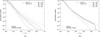 |
Fig. 12 Granulation power spectra for r0 = 6 cm. MMFBD = MAO. (a) Without SD. (b) With SD. |
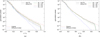 |
Fig. 13 Granulation power spectra for r0 = 10 cm. MMFBD = MAO. (a) Without SD. (b) With SD. |
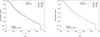 |
Fig. 14 Granulation power spectra for r0 = 15 cm. MMFBD = MAO. (a) Without SD. (b) With SD. |
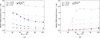 |
Fig. 15 RMS wavefront error not including tip and tilt for granulation data, (a) Without SD. (b) With SD. |
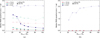 |
Fig. 16 RMS wavefront error not including tip and tilt for point source data, (a) Without SD. (b) With SD. |
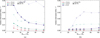 |
Fig. 17 Wavefront tilt errors as image shifts for granulation data, (a) Without SD. (b) With SD. |
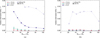 |
Fig. 18 Wavefront tilt errors as image shifts for point source data, (a) Without SD. (b) With SD. |
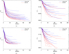 |
Fig. 19 Convergence for processing of datasets with r0 ∈ {6, 10, 15} cm and MMFBD = MAO ∈ {22, 42, 62, 102}. L/L0 is the error metric normalized with its initial value, (a) Granulation without FD. (b) Point source without FD. (c) Granulation with FD. (d) Point source with FD. |
4.1.3 Local minima
For point source data, with SD but without FD, the wavefront errors are almost zero except for r0 = 6 cm; see Fig. 19. For 6 cm, the errors are about as large as with granulation data. This suggests that the MFBD model fits converged to local minima and that there are global minima at the correct solutions – perhaps for both point sources and granulation.
In the MOMFBD code (see Sect. 4.5), the following strategy for avoiding local minima is implemented. The fitting starts with a small subset of the modes, by default the first M1 = 5 modes; it lets those converge for a few iterations, continues with M2 = 10 modes, lets them converge, and so on, until all the MMFBD modes are included in the fit. In other words, we are fitting first  , then
  , and so on, and finally
  . By allowing the more significant low-order modes to get started in the right direction, this scheme improves the chances that the fit converges to the global minimum. The wavy pattern in Fig. 19 and mentioned above is caused by these repeated increases in the number of fitted coefficients.
However, as SD also improves the convergence, and reduces the risk for convergence to local minima, we may want to modify this scheme. SD with  means there is still a model mismatch during this process of increasing the number of fitted modes. When Mi low-order modes are fitted, and
  statistically represents the most high-order modes, there is still a mismatch in that modes Mi + 1 through MMFBD are not accounted for. One way to further improve the chances of global minimization might be to include the appropriate SDs while stepping up the number of fitted modes: when
  is fitted, use
  as the SD.
For data that are not AO-corrected, this is straight forward. For AO-corrected data, we have to address the fact that a subset of the unfitted modes are partially AO corrected, and so we should take this into account when calculating  . At this point, one might question whether or not we have to calibrate the efficiencies with which the AO corrects the modes, as is the case for Speckle or the method of Saranathan et al. (2021), and take decorrelation of modes with distance from the WFS lock point into account. We believe that this would not have to be done exactly, as it is not involved in the final convergence with MMFBD fitted modes and
  as the SDs. It should be possible to use very approximate efficiencies. This is something to keep in mind when actually implementing the improvement of this strategy.
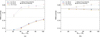 |
Fig. 20 Restored granulation contrast for varying r0 and MMFBD = MAO. (a) Without SD. (b) With SD. |
4.2 Synthetic data with varying r0
For real observations, r0 is not constant over the ~10 s period it takes to collect a dataset with a tuning spectro(polari)meter like SST/CRISP or SST/CHROMIS, and so for a more realistic simulation we need to allow for variations in r0. This is no problem for the SD concept, as each exposure j can have its own diversity coefficient, scaled to the r0 at the time of that exposure.
Scharmer et al. (2010) demonstrated that variations in r0 measured with the wide-field WFS of Scharmer & van Werkhoven (2010) with a temporal resolution of 2 s correlated with the RMS contrast in raw granulation data. Scharmer et al. (2019) showed 2 s r0 measurements from the SST AO WFS (upgraded in 2013) that also correlate with raw granulation data. These correlations suggest that these WFSs measure the total wavefronts from the whole height distribution of turbulence along the line of sight. In their temporal r0 plots, we can see that these meaningful r0 measurements can easily vary from 5 and 20 cm in a few seconds. We therefore constructed synthetic data from sets of 100 atmospheric wavefronts with r0 values spaced evenly in the ranges 10–14 cm, 8–16 cm, and 6–18 cm, respectively. (There are no moving phase sheets involved in the simulations, and so the j index is not a real time coordinate. Therefore it is of little importance that the r0 values are “sorted” this way.)
We then MFBD-processed these data as before, with and without FD and with and without SD, and the  SD contributions scaled to the individual r0 values for each simulated wavefront. We processed only a subset of the different MAO values. The MFBD inversions were initialized with the wavefront coefficients at their true values, because we wanted to evaluate the optimum fits rather than the risk of convergence to local minima.
The restored contrasts, shown in Fig. 20, are remarkably similar for the different r0 distributions. Comparing the results with constant r0 in Figs. 7 and 9, the FD contrasts without SD for varying r0 are similar to those of the constant r0 = 6, 8, or 10 cm datasets, while with SD the contrasts are consistently correct for constant and varying r0. Without FD, the contrasts without SD are overestimated for varying r0 while they are not for constant r0. With SD, processing the varying r0 data without FD gives similar results to the constant r0 = 12, 15, and 20 cm data. Varying r0 does not seem to be a problem for the SD methods.
4.3 Errors in r0
The SD component  depends on r0, which begs the questions of how sensitive the proposed method is to errors in r0 and of whether or not it would be possible to include r0 as an unknown parameter in the MFBD model fitting. We can examine some aspects of these questions without actually implementing the functionality in the redux MOMFBD code. We can investigate the effects of errors in the r0 values used to calculate the SD
  components.
The errors to consider may be guided by the 2 s resolution r0 measurements mentioned in Sect. 4.2. There may be smoothed-out variations on even shorter timescales, although they can be expected to be much smaller than the variations in the measurements themselves. This would apply to both negative and positive peaks. It seems prudent to test with random errors of at least a few percent. Below, we also examine the effect of systematic errors of similar magnitudes in the measured r0.
For testing the sensitivity to such errors, we used the varying-r0 data from Sect. 4.2. We scaled the  components to r0 values with normal-distributed random errors added to the true values, as well as systematic errors. We processed with MMFBD = MAO and initialized to the correct MMFBD wavefront coefficients as above.
Figure 21 shows the results with random errors in r0. The errors were drawn from a normal distribution with standard deviations in the range 0%–8%. We evaluated the error in the restored RMS contrast (the difference between the true image contrast and the estimated contrast) as well as the error metric L; see Eq. (10). The contrast errors are small, less than 1% for random errors ≲ 6%. The normalized error metric (unity for zero r0 error) is clearly at a minimum near zero error, and so it might be possible to converge to correct r0 values by including the SDs in the model fitting. In spite of initializing with the correct wavefront coefficients, the error metrics show signs of convergence to local minima for random errors larger than ~6%.
Figure 22 shows the results from adding systematic errors in the range -16% to 16% to r0. The contrast errors are larger for the data sets with a larger range of r0 values, in particular with less AO correction. The contrast and metric curves are smoother than for the random errors. There are clear minima in the metric near 0% error for all the data sets, which suggests it might be possible to fit for these errors as well.
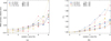 |
Fig. 21 Results from using MFBD with FD and SD on the same data as in Fig. 20 but with random errors in the assumed r0. (a) RMS contrast, relative error, (b) Converged error metric L, normalized to zero error in r0. |
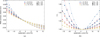 |
Fig. 22 Results from using MFBD with FD and SD on the same data as in Fig. 20 but with systematic errors in the assumed r0. (a) RMS contrast, relative error, (b) Converged error metric L, normalized to zero error in r0. |
4.4 Pretending varying r0 are constant
In the spirit of Speckle, we might also want to process data with varying r0 as if r0 were constant during the collection interval. Figure 23 shows the impact of this hypothetical situation on the restored RMS contrast as a function of the constant r0 used when calculating the SD coefficients for the three datasets with varying r0, as well as the converged error metric. As when processing the random and systematic errors in r0, we initialized with the correct MMFBD coefficients.
The contrast errors are fairly large, even with r0 within the range of the values included in the input. There is no clear indication for how the constant r0 should be calculated. The arithmetic average is 12 cm for all three datasets, while the optimum assumed r0 seem to vary within the upper half of the individual ranges based on where the contrasts cross the correct value. The error metrics seem to have minima around the crossing points, but these are too shallow (and, in the 6–18 cm case, show too much variability, probably because of local minima) to give any confidence that including a constant r0 would converge to a useful value if included as an unknown in the MFBD processing. Assuming a constant r0 value for the SD processing would probably require figuring out how to properly average r0 values measured within the collection interval. Furthermore, if the individual r0 values are available, there is no reason not to use them.
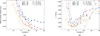 |
Fig. 23 Results from using MFBD with FD and SD on the same data as in Fig. 20 but with a constant assumed r0. The vertical dotted lines represent the limits of the r0 intervals, (a) RMS contrast, relative error, (b) Converged error metric L, normalized to its minimum. |
4.5 Software
For the processing, we used the Redux fork (Löfdahl et al. 2021) of the MOMFBD code by van Noort et al. (2005) based on the linear equality constraint (LEC) formulation of MFBD and PD by Löfdahl (2002). Redux is maintained by one of the authors of the present paper (T.H.).
In the Redux code, KL modes are by default implemented as sums of Zernike polynomials 2–2000 following Roddier (1990). An exception is that we use pure Zernike tip and tilt modes instead of the KL counterparts. This is in order to make it easier to realize (parts of) large tip and tilt coefficients as a change in subfield position. This makes the tip/tilt modes not quite orthogonal to the first few of the following modes and might change the covariance slightly, but should not cause any problem for the higher order modes that make up τM.
We note that the LEC formulation of MFBD has no problems with representing the SD mode of processing, which was completely unanticipated when it was devised 20 yr ago. Only relatively minor changes to the code were required: mainly the reading of diversity modes from a file instead of internally generating the Zernike focus mode as for FD only. There were also a few changes related to preprocessing of raw data, as the code is by default set up for the processing of real solar data with an extended object that is larger than the FOV. The code can now optionally skip certain steps related to intensity normalization and windowing and leave it to the user to provide the data in the appropriate state.
5 Discussion
Our results are obtained with very idealized data (no noise, no anisoplanatism, simple AO correction with the same modes as used in the MFBD processing) and do not necessarily indicate that the performance would be the same with real data. However, comparisons with the same data, processed both with and without SD, should show the advantages of using SD, but the extent of these advantages remains to be evaluated with real data for particular instruments and is outside the scope of this paper.
The SD representation of the high-order mode contribution combines the advantages of MFBD-based methods with some of those of Speckle. As is the case for Speckle, the contrast and power spectrum is corrected for the full range of wavefront modes. But an important advantage with MFBD over Speckle is retained, namely that the low-order modes are corrected without calibration of the performance of the AO in the presence of anisoplanatism. Moreover, the MFBD approach blindly compensates for all low-order aberrations irrespective of their origin being from the optics or from the atmospheric turbulence, and regardless of whether these aberrations obey Kolmogorov statistics. The high-order modes that are not AO corrected are also not subject to varying correction over the FOV. Although the wave-fronts vary spatially due to anisoplanatism, we can still expect r0 to be the same over the FOV.
The procedure for calculating  used in this work still uses finite sums of modes, although to Msim ≫ MMFBD. In hindsight, it would have been better to make nonparameterized simulated wavefronts (e.g., Nagaraju & Feller 2012) and instead subtract the best-fit
  wavefront, which is similar to the procedure used by Saranathan et al. (2021). We plan to switch to this approach when continuing the development of this method and adapting it to real data.
The results seem fairly robust to errors in r0. In particular, random errors around r0 measured with a temporal resolution of a few seconds should not be a problem. The method is formulated so that if r0 measurements with temporal resolution are known, they are a natural part of the problem formulation. Some of our results indicate it might be possible to estimate r0 as an additional fit parameter along with the low-order wavefront mode parameters.
It seems possible to process data with varying r0 as if r0 were constant during the collection interval. However, as the SD method fully supports using varying r0 we do not see any advantage of using this option, in particular as it is not obvious how to average the r0 values.
Normally, the better AO corrections are considered to be those that remove more of the wavefront, because uncorrected aberrations typically reduce the contrast and hide signal in the noise. On the other hand, MFBD converges to better solutions when it has fewer parameters to fit. With SD, we want the number of fitted modes to be at least as large as the number of AO-corrected modes. If the observations are not noise limited, this potentially creates a trade-off between AO correction with many modes and using a smaller number of well-defined modes. The lower limit for the number of modes to use is then set by the ability of the image-formation model to represent the resolution-critical cores of the PSFs.
We have shown the results of simulation experiments with synthetic data mimicking AO-corrected observational data in that the coefficients of the MAO lowest order modes were reduced by half from the random values following Kolmogorov statistics. While these data are the most interesting for our own processing needs, we did also process synthetic data without such simulated AO correction. We do not show those results here and we do not discuss them in detail. However, we do note that the SD extension of MFBD image restoration works for such data as well. The data are more degraded for the same r0 than the AO-corrected data, and so the results are worse, as expected. However, as with AO correction, SD does improve the wavefront sensing and restored contrasts. Without AO correction, SD is easier to use in the sense that there is no MAO that limits the choice of MMFBD and there is no partial correction to take into account when increasing the number of fitted modes in steps from 5 to MMFBD. We believe it would be beneficial to include SD in all MFBD problems where the wavefront aberrations follow Kolmogorov statistics. Or rather, for all problems where the statistics are known.
In the formulation of Scharmer et al. (2010), the corrective transfer function is based on an ensemble average of many OTFs based on independent random wavefronts with the correct r0. We can use a single random wavefront per exposure in the SD method presented here because our data sets consist of many exposures, and so the SD correction does include an ensemble of independent random wavefronts because of that. However, MOMFBD processing of line scans from imaging spectro(polari)meters such as CRISP or CHROMIS (see, e.g., Löfdahl et al. 2021) may require more consideration. While such datasets usually have approximately 100 or more WB images collected during the scan, for each NB tuning (and polarimetric state) only about 10 exposures are usually collected. This may be too few for a single random wavefront per state. If this is the case, the optimum processing strategy may be to use the post-restoration method of Scharmer et al. (2010) on the NB data based on the low-order wavefronts estimated with SD. This is an issue that should be addressed when we adapt SD for use with real SST data.
The NN MFBD method of Asensio Ramos & Olspert (2021) shares the finite wavefront parameterization with traditional MFBD and should have the same problem with restoring to correct power and contrast. We expect that such NN methods would benefit from including SD in their image formation model, just like traditional MFBD.
Speckle for AO-corrected data no longer needs r0 measured from the spectral ratio, as r0 can be obtained from the AO WFS. However, the spectral ratio is instead used for measuring the efficiencies of the AO correction for the corrected modes, and for monitoring how those efficiencies degrade with distance from the WFS lock point. Interestingly, Peck et al. (2017) added random noise to the efficiencies and found that this did not change the photometry of the restored data significantly. This is similar to our experience; we find that the details in the high-order contributions to the wavefronts are of little importance, as long as the statistics are correct.
6 Conclusions
We present a novel extension to the family of versatile wavefront-sensing and image-restoration methods that are based on MFBD, including PD, which we refer to as statistical diversity (SD). This is used to statistically represent high-order tail contributions to the unknown wavefronts so that the high-order mode coefficients do not have to be included as unknowns in the fitted model parameters. We tested SD with ideal, synthetic data. When combined with traditional PD, or FD as we refer to it in this paper, it comes with some important improvements: (1) The PSFs include the wide wing “halos” that are responsible for a major contribution to stray light in the restored images, and the results are more consistent contrasts and power spectra in the restored images. (2) The accuracy of the parameter estimates that are included in the fitted model is improved significantly.
Statistical diversity does not increase the number of free model parameters, and does not require calibration of the AO correction, either at the WFS lock point or as it degrades with distance from it. SD combines the system-diagnostic ability of MFBD-based methods (measures fixed aberrations and partially AO-corrected aberrations of low order, which affect the core of the PSFs necessary for restoring diffraction-limited resolution) with the known statistics of atmospheric turbulence exploited by Speckle methods (compensating for high-order modes that mainly affect the power spectrum and thereby the contrast). The method also has the potential to improve the convergence, in that the low-order parameters seem to reach their final values more easily when the total effect of multiple high-order modes is taken into account. The convergence could be improved further by adapting the SD contribution to the existing scheme of starting with only a few modes and then increasing the number of fitted modes step by step until the full MMFBD is reached.
Acknowledgements
M.G.L. is grateful to Göran Scharmer for carefully reading the manuscript and discussing our results, to Friedrich Wöger for interesting discussions and for patiently answering questions about Speckle methods, and to Michiel van Noort for explaining details about his recent work. This work was carried out as a part of the SOLARNET project, supported by the European Union’s Horizon 2020 research and innovation programme under grant agreement No. 824135. The Institute for Solar Physics is supported by a grant for research infrastructures of national importance from the Swedish Research Council (registration number 2017-00625).
References
- Asensio Ramos, A., & Olspert, N. 2021, A&A, 646, A100 [NASA ADS] [CrossRef] [EDP Sciences] [Google Scholar]
- Asensio Ramos, A., de la Cruz Rodriguez, J., & Pastor Yabar, A. 2018, A&A, 620, A73 [NASA ADS] [CrossRef] [EDP Sciences] [Google Scholar]
- Beard, A., Wöger, F., & Ferayorni, A. 2020, Proc. SPIE, 11452, 114521X [Google Scholar]
- Berger, T. E., Löfdahl, M. G., Shine, R. A., & Title, A. M. 1998, ApJ, 495, 973 [NASA ADS] [CrossRef] [Google Scholar]
- Berger, T. E., Löfdahl, M. G., & Bercik, D. J. 2002, BAAS, 34, 953 [NASA ADS] [Google Scholar]
- Berger, T. E., Rouppe van der Voort, L. H. M., Löfdahl, M. G., et al. 2004, A&A, 428, 613 [NASA ADS] [CrossRef] [EDP Sciences] [Google Scholar]
- Carlsson, M., Stein, R. F., Nordlund, Å., & Scharmer, G. 2004, ApJ, 610, L137 [NASA ADS] [CrossRef] [Google Scholar]
- de la Cruz Rodríguez, J. 2019, A&A, 631, A153 [NASA ADS] [CrossRef] [EDP Sciences] [Google Scholar]
- de la Cruz Rodríguez, J., Leenaarts, J., Danilovic, S., & Uitenbroek, H. 2019, A&A, 623, A74 [Google Scholar]
- Denker, C., Mascarinas, D., Xu, Y., et al. 2005, Sol. Phys., 227, 217 [NASA ADS] [CrossRef] [Google Scholar]
- Esteban Pozuelo, S., de la Cruz Rodriguez, J., Drews, A., et al. 2019, ApJ, 870, 88 [NASA ADS] [CrossRef] [Google Scholar]
- Fried, D. L. 1966, J. Opt. Soc. Am., 54, 1372 [NASA ADS] [CrossRef] [Google Scholar]
- Gonsalves, R. A., & Chidlaw, R. 1979, in Proc. SPIE, Applications of Digital Image Processing III, ed. A. G. Tescher, 207, 32 [Google Scholar]
- Labeyrie, A. 1970, A&A, 6, 85 [Google Scholar]
- Langhans, K., Scharmer, G. B., Kiselman, D., Löfdahl, M. G., & Berger, T. E. 2005, A&A, 436, 1087 [NASA ADS] [CrossRef] [EDP Sciences] [Google Scholar]
- Löfdahl, M. G. 2002, in Proc. SPIE, Image Reconstruction from Incomplete Data II, eds. P. J. Bones, M. A. Fiddy, & R. P. Millane, 4792, 146 [Google Scholar]
- Löfdahl, M. G. 2016, A&A, 585, A140 [NASA ADS] [CrossRef] [EDP Sciences] [Google Scholar]
- Löfdahl, M. G., & Scharmer, G. B. 1994, A&As, 107, 243 [Google Scholar]
- Löfdahl, M. G., & Scharmer, G. B. 2012, A&A, 537, A80 [Google Scholar]
- Löfdahl, M. G., Hillberg, T., de la Cruz Rodríguez, J., et al. 2021, A&A, 653, A68 [Google Scholar]
- Molodij, G., & Rousset, G. 1997, J. Opt. Soc. Am. A, 14, 1949 [NASA ADS] [CrossRef] [Google Scholar]
- Morosin, R., de la Cruz Rodríguez, J., Díaz Baso, C. J., & Leenaarts, J. 2022, A&A, 664, A8 [NASA ADS] [CrossRef] [EDP Sciences] [Google Scholar]
- Nagaraju, K., & Feller, A. 2012, Appl. Opt., 51, 7953 [NASA ADS] [CrossRef] [Google Scholar]
- Noll, R. J. 1976, J. Opt. Soc. Am., 66, 207 [Google Scholar]
- Paxman, R. G., Schulz, T. J., & Fienup, J. R. 1992a, J. Opt. Soc. Am. A, 9, 1072 [CrossRef] [Google Scholar]
- Paxman, R. G., Schulz, T. J., & Fienup, J. R. 1992b, in Technical Digest Series, Signal Recovery and Synthesis IV, Optical Society of America, 11, 5 [Google Scholar]
- Paxman, R. G., Seldin, J. H., Löfdahl, M. G., Scharmer, G. B., & Keller, C. U. 1996, ApJ, 466, 1087 [NASA ADS] [CrossRef] [Google Scholar]
- Peck, C. L., Wöger, F., & Marino, J. 2017, A&A, 607, A83 [NASA ADS] [CrossRef] [EDP Sciences] [Google Scholar]
- Rimmele, T. R., & Marino, J. 2011, Living Rev. Sol. Phys., 8, 2 [Google Scholar]
- Roddier, F. 1998, PASP, 110, 837 [NASA ADS] [CrossRef] [Google Scholar]
- Roddier, N. 1990, Opt. Eng., 29, 1174 [NASA ADS] [CrossRef] [Google Scholar]
- Rouppe van der Voort, L. H. M., Joshi, J., Henriques, V. M. J., & Bose, S. 2021, A&A, 648, A54 [NASA ADS] [CrossRef] [EDP Sciences] [Google Scholar]
- Saranathan, S., van Noort, M., & Solanki, S. K. 2021, A&A, 653, A17 [NASA ADS] [CrossRef] [EDP Sciences] [Google Scholar]
- Scharmer, G. 2017, in SOLARNET IV: The Physics of the Sun from the Interior to the Outer Atmosphere, 85 [Google Scholar]
- Scharmer, G. B., & van Werkhoven, T. I. M. 2010, A&A, 513, A25 [NASA ADS] [CrossRef] [EDP Sciences] [Google Scholar]
- Scharmer, G. B., Brown, D. S., Pettersson, L., & Rehn, J. 1985, Appl. Opt., 24, 2558 [NASA ADS] [CrossRef] [Google Scholar]
- Scharmer, G. B., Gudiksen, B. V., Kiselman, D., Löfdahl, M. G., & Rouppe van der Voort, L. H. M. 2002, Nature, 420, 151 [CrossRef] [Google Scholar]
- Scharmer, G. B., Bjelksjö, K., Korhonen, T. K., Lindberg, B., & Pettersson, B. 2003a, in Proc. SPIE, Innovative Telescopes and Instrumentation for Solar Astrophysics, eds. S. Keil, & S. Avakyan, 4853, 341 [Google Scholar]
- Scharmer, G. B., Dettori, P., Löfdahl, M. G., & Shand, M. 2003b, in Proc. SPIE, Innovative Telescopes and Instrumentation for Solar Astrophysics, eds. S. Keil, & S. Avakyan, 4853, 370 [Google Scholar]
- Scharmer, G. B., Narayan, G., Hillberg, T., et al. 2008, ApJ, 689, L69 [Google Scholar]
- Scharmer, G. B., Löfdahl, M. G., van Werkhoven, T. I. M., & de la Cruz Rodríguez, J. 2010, A&A, 521, A68 [NASA ADS] [CrossRef] [EDP Sciences] [Google Scholar]
- Scharmer, G. B., Henriques, V. M. J., Kiselman, D., & de la Cruz Rodríguez, J. 2011, Science, 333, 316 [Google Scholar]
- Scharmer, G. B., Löfdahl, M. G., Sliepen, G., & de la Cruz Rodríguez, J. 2019, A&A, 626, A55 [NASA ADS] [CrossRef] [EDP Sciences] [Google Scholar]
- Schulz, T. J. 1993, J. Opt. Soc. Am. A, 10, 1064 [NASA ADS] [CrossRef] [Google Scholar]
- Seldin, J. H., & Paxman, R. G. 1994, in Proc. SPIE, Image reconstruction and restoration, eds. T. J. Schultz, & D. L. Snyder, 2302, 268 [Google Scholar]
- Socas-Navarro, H., de la Cruz Rodríguez, J., Asensio Ramos, A., Trujillo Bueno, J., & Ruiz Cobo, B. 2015, A&A, 577, A7 [NASA ADS] [CrossRef] [EDP Sciences] [Google Scholar]
- Spruit, H. C., Scharmer, G. B., & Löfdahl, M. 2010, A&A, 521, A72 [NASA ADS] [CrossRef] [EDP Sciences] [Google Scholar]
- Uitenbroek, H., Tritschler, A., & Rimmele, T. 2007, ApJ, 668, 586 [NASA ADS] [CrossRef] [Google Scholar]
- van Noort, M., Rouppe van der Voort, L., & Löfdahl, M. G. 2005, Sol. Phys., 228, 191 [Google Scholar]
- Vissers, G. J. M., de la Cruz Rodriguez, J., Libbrecht, T., et al. 2019, A&A, 627, A101 [NASA ADS] [CrossRef] [EDP Sciences] [Google Scholar]
- von der Lühe, O. 1984, J. Opt. Soc. Am. A, 1, 510 [CrossRef] [Google Scholar]
- von der Lühe, O. 1993, A&A, 268, 374 [NASA ADS] [Google Scholar]
- Wang, S., Chen, Q., He, C., et al. 2021, A&A, 652, A50 [NASA ADS] [CrossRef] [EDP Sciences] [Google Scholar]
- Wöger, F. 2010, Appl. Opt., 49, 1818 [CrossRef] [Google Scholar]
- Wöger, F., & von der Lühe, O. 2007, Appl. Opt., 46, 8015 [CrossRef] [Google Scholar]
- Wöger, F., von der Lühe, O., & Reardon, K. 2008, A&A, 488, 375 [NASA ADS] [CrossRef] [EDP Sciences] [Google Scholar]
All Tables
All Figures
|
Fig. 1 Example of an instantaneous wavefront phase ϕj split into ϕjM, a sum of the first M modes, and τjM, the residual tail of higher-order modes; see Eq. (4). The Strehl ratios are calculated for r0 = 6, 10, and 15 cm (corresponding to 1″.7, 1″.0, and 0″.5 seeing, respectively) with Eqs. (5) and (6), assuming a 97cm aperture and perfect compensation of ϕjM. The wavefront images are calculated with an upper limit of M = 1002; see Msim in Sect. 3.1 for comparison. |
| In the text | |
|
Fig. 2 Schematic representation of constraints and diversities for a dataset with five atmospheric wavefronts and FD. |
| In the text | |
|
Fig. 3 Schematic representation of constraints and diversities for the same data as in Fig. 2 but processed with both FD and SD. |
| In the text | |
|
Fig. 4 Synthetic “true” images, (a) 538 nm. (b) 630 nm. |
| In the text | |
|
Fig. 5 Contrasts for synthetic 538 nm granulation data. (a) With 50% AO correction of the MAO most significant KL modes. The error bars denote the standard deviation in each set of images. (b) Multiframe-deconvolved with the correct values of the coefficients for the MAO most significant KL modes, leaving |
| In the text | |
|
Fig. 6 Sample synthetic “raw” images with 50% AO correction up to mode MAO. Images degraded by first wavefront of a set of 100 random wavefronts. Grayscale as for the “true” image in Fig. 4. (a) Conventional in-focus images, (b) FD images. |
| In the text | |
|
Fig. 7 MFBD without SD. Restored granulation contrasts. |
| In the text | |
|
Fig. 8 MFBD without SD followed by post-restoration compensation for |
| In the text | |
|
Fig. 9 MFBD with SD. Restored granulation contrasts. |
| In the text | |
|
Fig. 10 Sample restored images using MFBD without SD. |
| In the text | |
|
Fig. 11 Sample restored images using MFBD with SD. (a) Without FD. (b) With FD. |
| In the text | |
|
Fig. 12 Granulation power spectra for r0 = 6 cm. MMFBD = MAO. (a) Without SD. (b) With SD. |
| In the text | |
|
Fig. 13 Granulation power spectra for r0 = 10 cm. MMFBD = MAO. (a) Without SD. (b) With SD. |
| In the text | |
|
Fig. 14 Granulation power spectra for r0 = 15 cm. MMFBD = MAO. (a) Without SD. (b) With SD. |
| In the text | |
|
Fig. 15 RMS wavefront error not including tip and tilt for granulation data, (a) Without SD. (b) With SD. |
| In the text | |
|
Fig. 16 RMS wavefront error not including tip and tilt for point source data, (a) Without SD. (b) With SD. |
| In the text | |
|
Fig. 17 Wavefront tilt errors as image shifts for granulation data, (a) Without SD. (b) With SD. |
| In the text | |
|
Fig. 18 Wavefront tilt errors as image shifts for point source data, (a) Without SD. (b) With SD. |
| In the text | |
|
Fig. 19 Convergence for processing of datasets with r0 ∈ {6, 10, 15} cm and MMFBD = MAO ∈ {22, 42, 62, 102}. L/L0 is the error metric normalized with its initial value, (a) Granulation without FD. (b) Point source without FD. (c) Granulation with FD. (d) Point source with FD. |
| In the text | |
|
Fig. 20 Restored granulation contrast for varying r0 and MMFBD = MAO. (a) Without SD. (b) With SD. |
| In the text | |
|
Fig. 21 Results from using MFBD with FD and SD on the same data as in Fig. 20 but with random errors in the assumed r0. (a) RMS contrast, relative error, (b) Converged error metric L, normalized to zero error in r0. |
| In the text | |
|
Fig. 22 Results from using MFBD with FD and SD on the same data as in Fig. 20 but with systematic errors in the assumed r0. (a) RMS contrast, relative error, (b) Converged error metric L, normalized to zero error in r0. |
| In the text | |
|
Fig. 23 Results from using MFBD with FD and SD on the same data as in Fig. 20 but with a constant assumed r0. The vertical dotted lines represent the limits of the r0 intervals, (a) RMS contrast, relative error, (b) Converged error metric L, normalized to its minimum. |
| In the text | |
Current usage metrics show cumulative count of Article Views (full-text article views including HTML views, PDF and ePub downloads, according to the available data) and Abstracts Views on Vision4Press platform.
Data correspond to usage on the plateform after 2015. The current usage metrics is available 48-96 hours after online publication and is updated daily on week days.
Initial download of the metrics may take a while.