Fig. 2
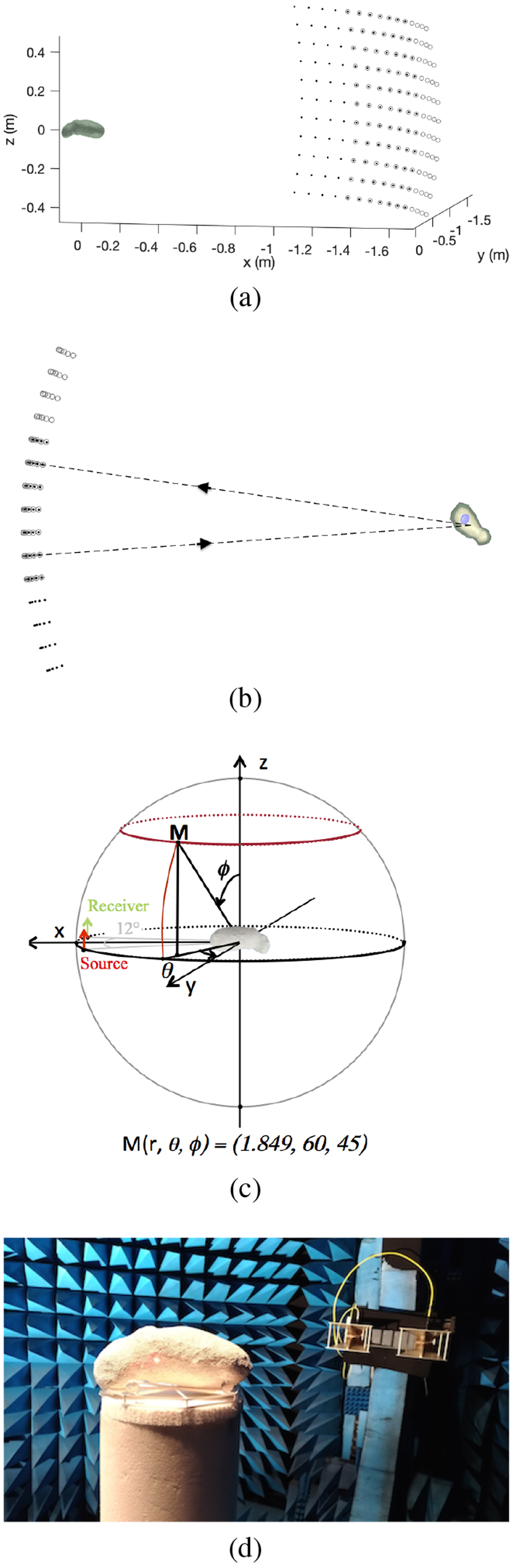
Measurement configuration. (a) Complete measurement configuration depicting the transmitter points with solid, black points and the receiver positions in gray circles. (b) Signal path for the centermost transmitter-receiver pair showing a cut-in view through the target. The view is along the z-axis. The source is at the position ϕs = 90°, θs = 174° and the receiver at ϕr = 90°, θr = 186°. (c) Experimental configuration with the angles definition. (d) Photograph of the analog object and the transmitter-receiver pair in the anechoic chamber of the CCRM in Marseille. The transmitter-receiver pair is seen in the background and the 3D-printed support plate applied for positioning is visible under the analog model.
Current usage metrics show cumulative count of Article Views (full-text article views including HTML views, PDF and ePub downloads, according to the available data) and Abstracts Views on Vision4Press platform.
Data correspond to usage on the plateform after 2015. The current usage metrics is available 48-96 hours after online publication and is updated daily on week days.
Initial download of the metrics may take a while.