| Issue |
A&A
Volume 631, November 2019
|
|
|---|---|---|
| Article Number | A59 | |
| Number of page(s) | 8 | |
| Section | Interstellar and circumstellar matter | |
| DOI | https://doi.org/10.1051/0004-6361/201833808 | |
| Published online | 21 October 2019 | |
Signatures of diffuse interstellar gas in the Galaxy Evolution Explorer all-sky survey ★
AEGORA Research Group, Facultad de CC Matemáticas, Universidad Complutense de Madrid,
28040
Madrid,
Spain
e-mail: aig@ucm.es
Received:
9
July
2018
Accepted:
9
September
2019
Context. The all-sky survey run by the Galaxy Evolution Explorer (GALEX AIS) mapped about 85% of the Galaxy at ultraviolet (UV) wavelengths and detected the diffuse UV background produced by the scattering of the radiation from OBA stars by interstellar dust grains. Against this background, diffuse weak structures were detected as well as the UV counterparts to nebulae and molecular clouds.
Aims. To make full profit of the survey, unsupervised and semi-supervised procedures need to be implemented. The main objective of this work is to implement and analyze the results of the method developed by us for the blind detection of ISM features in the GALEX AIS.
Methods. Most ISM features are detected at very low signal levels (dark filaments, globules) against the already faint UV background. We have defined an index, the UV background fluctuations index (or UBF index), to identify areas of the sky where these fluctuations are detected. The algorithm is applied to the images obtained in the far-UV (1344–1786 Å) band since this is less polluted by stellar sources, facilitating the automated detection.
Results. The UBF index is shown to be sensitive to the main star forming regions within the Gould’s Belt, and to some prominent loops like Loop I or the Eridanus and Monogem areas. The catalog with the UBF index values is made available online to the community.
Key words: ultraviolet: ISM / methods: statistical / catalogs / dust, extinction / ISM: general
Full Table 1 is available at the CDS via anonymous ftp to cdsarc.u-strasbg.fr (130.79.128.5) or at http://cdsarc.u-strasbg.fr/viz-bin/cat/J/A+A/631/A59 and at jcuva.ucm.es
© ESO 2019
1 Introduction
In 2003, the GALaxy Evolution eXplorer (GALEX) was launched into low Earth orbit. The mission lasted ten years and was equipped with wide-field cameras that provided simultaneous far-ultraviolet (FUV) (1344–1786 Å) and near-ultraviolet (NUV) (1771–2831 Å) imaging using photon-counting MCP-type detectors (Martin et al. 2005). GALEX ran the first all-sky survey at UV wavelengths providing highly valuable data for interstellar medium (ISM) studies.
The UV radiation produced by the massive OBA stars in the Galaxy is scattered and absorbed by the dust in the ISM providing important clues to the albedo and composition of the grains (Saslaw & Gastaud 1969; Draine 2003), especially at the low end of the size distribution. An additional contribution to the UV ISM radiation comes from the molecular hydrogen in the envelopes of the molecular clouds that efficiently absorbs the Lyman-α photons from the UV background and reprocess them into H2 fluorescent emission in the electronic Lyman band; these transitions are significantly stronger than the infrared (magnetic quadrupole) transitions often used in ISM studies. Moreover, the envelopes of ionized nebulae are detected in the GALEX bands; the resonance transitions from neutral (H I, C I, O I) singly ionized (Mg II, C II, O II, Fe II, Al II) or multiply ionized gas (C IV, Si IV, N V) are observed within the range covered by GALEX.
Some examples of GALEX images of interstellar objects are shown in Figs. 1–3. The Rosette nebula is an excellent example of a reflection nebula. Rosette is illuminated by a cluster of B8–9 stars, and dense (dark) filaments are observed against the bright background produced by the radiation scattered by the icy dust grains in the nebula (see Fig. 1).
GALEXsensitivity to faint absorption nebula is shown in Fig. 2 for Barnard 29. The exposure time is about 200 s in the FUV band, significantly less than required to obtain an image of the dark clump with similar signal-to-noise ratio (S/N) in the optical range.
The Vela loop is shown in Fig. 3. The loop is prominent both in the NUV (Fe II, C II) and in the FUV (C IV, Si IV, He II) bands and the braiding of the filaments is neatly observed even in the ~ 90 s exposure time images of the GALEX All-Sky Imaging Survey (AIS).
All these features were observed at intensity levels similar to the UV background level. The dark globules in Fig. 2 would have passed unnoticed to a simple inspection of the GALEX tiles.
During its lifetime, the GALEX AIS produced 28 707 images (or tiles) in the FUV band and 34 285 images in the NUV band (Bianchi et al. 2014), with a total sky coverage of 26 000 square degrees. The wealth of information contained inGALEX AIS images is huge and requires unsupervised procedures to search for weak interstellar structures. This work deals with this challenge; we describe, implement, and analyze the results of the method we developed for the blind detection of nebular structures, condensations, and filaments in the GALEX survey. In Sect. 2 we describe the method and derive the index to search for diffuse features in the GALEX AIS. In Sect. 3 the results are presented and compared with other galactic surveys. The article concludes with a short summary.
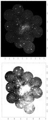 |
Fig. 1 Rosette nebula as seen by GALEX in the NUV band (Rosette was not mapped in the FUV band). The image is a compositeof 13 NUV images assembled using the MOSAIX tool (Armengot et al. 2014). Top panel: high contrast image. Bottom panel: same image in logarithmic scale to enhance the structures at low signal level. Coordinates are ICRS: right ascension increases from right to left (in degrees) and declination from bottom to top. |
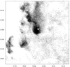 |
Fig. 2 Barnard 29 imaged in the FUV band by GALEX AIS. The original GALEX images have been mosaiced together (coordinatesas in Fig. 1). |
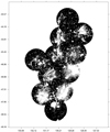 |
Fig. 3 Vela filaments observed by GALEX in the NUV band. The image is a composite of 11 NUV images (coordinates as in Fig. 1). |
2 Description of the method
For each field imaged by GALEX, the mission provides detailed information including raw data, calibration files, and the enddata products (see Morrissey et al. 2007), all accessible through the Mikulski Archive of Space Telescopes1 (MAST). Among the whole set of data products provided for each field or tile, there are three relevant to this work:
- (1)
the flux calibrated intensity map (extension -int in the archive);
- (2)
the sky background in the area as modeled by the mission and implemented in the data pipeline (extension -skybg in the archive);
- (3)
the final background subtracted image (extension -intbgsub in the archive).
Upon the completion of the mission, GALEX AIS data products were used to study the Galactic UV background at the Sun’s location in the Galaxy. Murthy et al. (2010) built a map of the local UV background at NUV and FUV wavelengths using the sky background data derived by the mission (the -skybg files). An all-sky map of the UV background was provided after normalization by the exposure time and mosaicking the full set of -skybg images into an Aitoff projection. Later work by Hamden et al. (2013) applied a more sophisticated treatment that involved the removal of the point-like UV sources from the intensity images (-int) by implementing mask files including the effect of dust grains scattering of the UV radiation from point-like sources. For our work, we used the end data products from the mission, the calibrated images (-intbgsub images) distributed through the MAST.
The first challenge for the blind detection of ISM features is their low signal; ISM filaments are observed as small fluctuations over the background that it is already very weak. For instance, the FUV background is < 1 × 10⁻² counts s−1 pixel−1 in the Taurus molecular complex (bgal ≃−20°) hence, less than one photon is detected per pixel in the ~100 s of exposure time, characteristic of GALEX AIS (Morrissey et al. 2007). To reach statistically significant levels, the images have been re-binned to resolution elements (resels) of 30 × 30 pix2 (or 45 × 45 arcsec2); in this manner, the count rate is raised to tens of counts s−1 per resel even at high galactic latitudes. We note that this degraded angular resolution is still significantly better than the resolution of the IRAS survey at 100 microns (Beichman et al. 1998). This binning is similar to that used by the GALEX mission to evaluate the UV background2.
After rebinning, the images were inverted3 to enhance the background. The statistical estimator of the background fluctuationsis computed over these rebinned and inverted images M with 64 × 64 elements M(i, j) as follows:
- 1.
all elements of matrix M are arranged into a vector V of 64 × 64 = 4096 elements such that element (i, j) in the matrix corresponds to element k in the vector with k = (j − 1) * 64 + i;
- 2.
subsets Vl with l ∈ [1, 10] are defined from V, so that V l = [V ((l − 1) × 400), V (l × 400 − 1)], each containing 400 elements;
- 3.
for each subset l the arithmetic mean, the maximum, and the minimum are computed: Mean (l), Maximum (l), and Minimum (l), respectively; an outlier detection algorithm was used;
- 4.
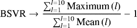
for each tile the background scale variability rating (BSVR) is computed. The BSVR is defined as
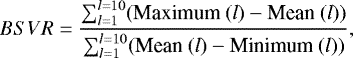 (1)
(1)with l running from 1 to 10, the number of subsets.
The process is illustrated in Fig. 4. The original GALEX image, as provided by MAST, is shown in the leftmost panel. Only the central square (1920 × 1920 pix2), marked in white in the image, is used for the calculation of the BSVR. This area is rebinned into resels of 30 × 30 pix2, as shown in the central panel. Then the value of each pixel is plotted in the right panel; pixels are read from top to bottom and from left to right. Thus, the first 1000 pixels correspond to the leftmost area of the image where no significant fluctuations (filaments) are detected, while the last 1000 pixels correspond to the rightmost area where the dark filaments are concentrated. This results in an increasing dispersion from the top left corner (pixel number 1) to the bottom right corner (pixel 4000).
The BSVR is calculated over the background-subtracted images -intbgsub files. Therefore, the BSVR is not be affected by any local or galactic UV background; even cirrus or the dust scattered light from bright sources should be removed in the pipeline processing4. However, as shown in Figs. 1–3, GALEX image processing does not remove reflection nebulae or dark clouds absorbing the UV background radiation. These are the targets to be detected using the BSVR.
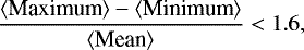
We note that as M is made of the inverse (rebinned) values, the contribution to the BSVR of the bright points or areas in the image (mainly point-like sources) is negligible, provided that there are not many of them and so do not affect significantly the mean. In this case, Mean (k) ≫Minimum (k), resulting in
 (2)
(2)
The number of point-like sources in the FUV band is one-tenth of those detected in the NUV band. Henceforth, the BSVR index is determined from the FUV images in the survey to optimize its performance.
The resulting BSVR all-sky map is plotted in Aitoff projection in Fig. 5. Two main features are clearly discernible: [1] the BSVR depends on the galactic latitude and [2] there are some clear stripes (maximum circles) where the BSVR is anomalously low.
In Fig. 6 the histogram of observed BSVR values per galactic latitude is represented. The butterfly pattern indicates that there are two neatly defined areas in the sky. Over most of the sky, the BSVR increases with galactic latitude; however, the area with BSVR < 0.6 does not follow the same trend.
The general dependence of the BSVR on galactic latitude is well fitted by a power law of sin |b|,
 (3)
(3)
with RMSE = 0.1185. The trend in Eq. (3) indicates that the BSVR is enhanced at high galactic latitudes with respect to low galactic latitudes. The examination of the tiles at high galactic latitudes shows no enhancements in the number of nebulae with respect to the lower latitude tiles; in fact, the opposite trend is observed. Moreover, as the BSVR is computedfrom the background subtracted files, it is not directly affected by the well-known dependency of the UV background on galactic latitude (Murthy 2014). However, the very low signal level in the observations at high galactic latitudes makes the BSVR very sensitive to the low level statistical fluctuations introducing an indirect dependency in the background level and the galactic latitude. This trend is not of astronomical origin, and here weintroduce the UV Background Fluctuations Index (UBFI) to correct for it. The UBFI is defined as
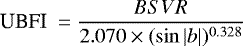 (4)
(4)
The UBFI histogram of occurrences is shown in Fig. 7. It displays a maximum at UBFI ≃ 1 that can be well fitted to a normal distribution with dispersion σ = 0.272 ± 0.001 that shows the goodness of fit in Eq. (3). Some excess is observed in the wings of the distribution produced by the outliers, the weak nebular structures we want to detect through the UBF index. We note that this trend indicates that the galactic UV background fluctuations are not fully subtracted out in the GALEX image processing pipeline.
There is also a secondary maximum at UBFI < 0.5 that comes from the areas with BSVR ≤ 0.6 in Figs. 5 and 6. In these areas
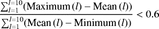 (5)
(5)
i.e., these index values trace areas of the sky where the UV background is unusually uniform. The pattern is most clearly recognizablein equatorial coordinates, both the Earth’s equator and some polar orbits are readily recognizable (see Fig. 8).
The main conclusion to be drawn is that the UV background is characterized by a natural level of fluctuation that is artificially damped in certain areas of the sky. This damping most likely results from the GALEX data processing.
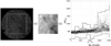 |
Fig. 4 Procedure to compute the BSVR. A sample GALEX image is displayed in the leftmost panel, as well as the central square used to compute the BSVR. This central square rebined into an image of 64 × 64 resels which is displayed in the central panel. From the inverse of this image, a vector, V, is constructed by re-arranging its elements (see text); they are plot in the right panel. The envelopes in this panel are constructed as follows: every 400 elements, the mean (white line), the maximum, and the minimum (bold dashed lines) are computed. The BSVR is determined from these values (see text for further details). |
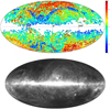 |
Fig. 5 Top: representation of the BSVR for the 83,081 GALEX AIS images processed in this work; data are plotted in Aitoff projection. Bottom: IRAS 100-micron map of the sky displayed for reference. |
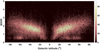 |
Fig. 6 BSVR index plotted vs. galactic latitude for all tiles in the GALEX AIS survey. |
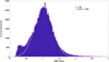 |
Fig. 7 Histogram of occurrences of the UBF index. The fit to a normal distribution is shown by a pink line; dispersion is indicated in the inset. |
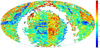 |
Fig. 8 All-sky map of the UBF index in equatorial coordinates (ICRS) and Aitoff projection. Shown is the band with low UBFI at theequator. |
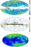 |
Fig. 9 Top: map of the UBF index in the area surveyed by GALEX. Middle: location of the galactic dust clouds according to DB2002; the E(B–V) values from the catalog are color-coded. Bottom: soft X-ray background measured by ROSAT (Snowden et al. 1995). |
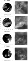 |
Fig. 10 Left: relative extinction maps for some areas of the Taurus-Auriga star forming complex. Right: same areas in the IRAS 100 microns maps. The main features extracted from the UV relative extinction maps are marked in both plots to test the overlap with IRAS; in these examples the match is significant. |
3 Results: UV background fluctuations derived from the GALEX FUV AIS
The UBF index all-sky map is built from the 83,081 GALEX AIS FUV tiles and represented in galactic coordinates (Aitoff projection) in Fig. 9 (top panel). The strongest fluctuations are observed around l = 90° towards Cepheus and the IC5146 star forming regions. The comparison with the Dutra and Bica catalog (Dutra & Bica 2002, hereafter DB2002) of galactic dust clouds shows a high degree of agreement. DB2002 results from the compilation of 21 catalogs that include from dense molecular clouds to the diffuse infrared cirrus in the Magnani et al. (1985) catalog. In Fig. 10 (middle panel), the location of the clouds is represented and the E(B–V), as per DB2002 work, is color-coded. Star forming regions like the Taurus-Auriga complex or Orion are readily recognizable in the UBFI map as already expected from previous works (see Gómez de Castro et al. 2015a,b and Beitia-Antero & Gómez de Castro 2017, for more details).
Additional areas with strong fluctuations are at high galactic latitudes, some seem to be associated with prominent ISM shells or loops such as the Eridanus loop or Loop I that are especially noticeable in the soft X-ray background map of the Galaxy built by the ROSAT mission (Snowden et al. 1995).
The catalog with the UBF index computed for the 83,081 GALEX AIS FUV tiles is available online at the Joint Center for Ultraviolet Astronomy5 and through the services of the Centre de Donneés Stellaires (CDS). For each GALEX AIS tile, the galactic and equatorial (ICRS) coordinates of the center of the field, as well as the UBF index are provided (see Table 1, for an excerpt). We note that there typically 2 or 3 entries per location in the sky since the AIS mapped the whole sky several times. As shown in the table, in most cases the UBFI is the same for all measurements of the same field. However, it should be noted that we occasionally detected discrepancies (see the first two entries in Table 1). These values are left as calculated in the catalog for reference.
UBF index from GALEX/AIS FUV images.
4 Interstellar clouds in the far UV
According to the histogram in Fig. 7, the fluctuations introduced by interstellar structures are expected to be at UBFI > 1.3, which corresponds to 2.5σ above the average (see also Fig. 9a). In general, good matches are found between the FUV structures and the infrared structures in the nearby molecular clouds. A good example is the Taurus-Auriga region. In Fig. 7, the FUV absorption is compared with the infrared emission for some dark globules and filaments in the area. In the left panels, the FUV maps are displayed in logarithmic scale; they are relative-extinction maps computed as
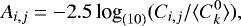 (7)
(7)
where Ci,j is the count rate in resel (i, j), and  is the average count rate in the tile. In the right panel, IRAS images (100 microns) of the same features are plotted. Key contours from the left panel (FUV) are overimposed in the right panel for guidance. We note that the FUV extinction AFUV scales with the column density of dust grains6 Nd as AFUV ∝ Nd, and the thermal emission F100μ is also expected to be proportional to Nd, thus roughly AFUV ∝ F100μ. In practice, the details of the grain composition, albedo, and size distribution will introduce deviations over this simple trend providing a unique tool for the characterization of dust grains.
There isnot, however, a similar good match with the diffuse structures detected by the Galactic Arecibo L-Band Feed Array H I (GALFA H I) survey. GALFA H I maps with unprecedented sensitivity and spatial resolution of 3.5 arc min, the distribution of neutral hydrogen in the 21 cm line (Begum et al. 2010). Ninety-six H I clouds were reported to have LSR velocities smaller than 90 km s−1 and, in principle, could be close enough to be detectable within the GALEX AIS. Although some good matches have been found, as shown in Fig. 11, most of the clouds have not been detected by GALEX, probably because of the limited depth of the GALEX AIS survey.
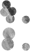 |
Fig. 11 Four of the best matches with H I clouds from the GALFA-H I survey. The images correspond to entries 5 (top left), 15 (top right), 6 (bottom left) and 54 (bottom right) in the catalog (Table 1 in Begum et al. 2010). |
5 Conclusions
In this work, we mined the FUV images in the GALEX all-sky survey to detect weak extended structures in the ISM. We derived an index, the UBF index, that can be reliably used to search for fluctuations of the FUV background in the sky. The UBFI is greater than 1.3 in the main nearby star forming complexes and some prominent loops in the ISM.
Acknowledgements
This work has been partly support by grants ESP2015-68908-R and ESP2017-87813-R from the Ministry of Science, Innovation and Universities of Spain.
References
- Armengot, M., Sanchez, N., Lopez-Santiago, J., et al. 2014, Ap&SS, 354, 113 [NASA ADS] [CrossRef] [Google Scholar]
- Begum, A., Stanimirović, S., Peek, J. E., et al. 2010, ApJ, 722, 395 [NASA ADS] [CrossRef] [Google Scholar]
- Beichman, C. A., Neugebauer, G., Habing, H. J., Clegg, P. E., & Chester, T. J. (1988), Infrared Astronomical Satellite (IRAS) catalogs and Atlases, explanatory Supplement, 2nd edn. (Hampton, VA: NASA Scientific and Technical Information Division), 1 [Google Scholar]
- Beitia-Antero, L., & Gomez de Castro, A. I. 2017, MNRAS, 469, 2531 [NASA ADS] [CrossRef] [Google Scholar]
- Bianchi, L. 2014, Ap&SS, 354, 103 [NASA ADS] [CrossRef] [Google Scholar]
- Bohlin, R. C., Savage, B. D., & Drake, J. F. 1978, ApJ, 224, 132 [NASA ADS] [CrossRef] [Google Scholar]
- Draine, B.T. 2003, ApJ, 598, 1017 [NASA ADS] [CrossRef] [Google Scholar]
- Dutra, C. M., & Bica, E. 2002, A&A, 383, 631 [NASA ADS] [CrossRef] [EDP Sciences] [Google Scholar]
- Gómez de Castro, A. I., Lopez-Santiago, J., Lopez-Martinez, F., et al. 2015a, ApJS, 216, 26 [CrossRef] [Google Scholar]
- Gómez de Castro, A. I., Lopez-Santiago, J., Lopez-Martinez, F., et al. 2015b, MNRAS, 449, 3867G [CrossRef] [Google Scholar]
- Hamden, E. T., Schiminovich, D., & Seibert, M. 2013, ApJ, 779, 180 [NASA ADS] [CrossRef] [Google Scholar]
- Magnani, L., Blitz, L., & Mundy, L. 1985, ApJ, 295, 402 [NASA ADS] [CrossRef] [Google Scholar]
- Martin, D. C., Fanson, J., Schiminovich, D., et al. 2005, ApJL, 619, L1 [NASA ADS] [CrossRef] [Google Scholar]
- Morrissey, P., Conrow, T., Barlow, T. A., et al. 2007, ApJS, 173, 682 [NASA ADS] [CrossRef] [Google Scholar]
- Murthy, J. 2014, ApJS, 213, 32 [NASA ADS] [CrossRef] [Google Scholar]
- Murthy, J., Henry, R. C., & Sujatha, N. V. 2010, ApJ, 724, 1389 [NASA ADS] [CrossRef] [Google Scholar]
- Saslaw, W. C., & Gaustad, J. E. 1969, Nature, 221, 160S [CrossRef] [Google Scholar]
- Snowden, S. L., Freyberg, M. J., Plucinsky, P. P., et al. 1995, ApJ, 454, 643 [NASA ADS] [CrossRef] [Google Scholar]
See, e.g., Fig. 5 in http://www.galex.caltech.edu/ researcher/techdoc-ch4.html
For a given extinction law, AFUV∕AV is constant and NH∕AV ≈ 1.8 × 10²¹ atoms cm−2 mag−1 (Bohlin et al. 1978) for the ISM.
All Tables
All Figures
|
Fig. 1 Rosette nebula as seen by GALEX in the NUV band (Rosette was not mapped in the FUV band). The image is a compositeof 13 NUV images assembled using the MOSAIX tool (Armengot et al. 2014). Top panel: high contrast image. Bottom panel: same image in logarithmic scale to enhance the structures at low signal level. Coordinates are ICRS: right ascension increases from right to left (in degrees) and declination from bottom to top. |
| In the text | |
|
Fig. 2 Barnard 29 imaged in the FUV band by GALEX AIS. The original GALEX images have been mosaiced together (coordinatesas in Fig. 1). |
| In the text | |
|
Fig. 3 Vela filaments observed by GALEX in the NUV band. The image is a composite of 11 NUV images (coordinates as in Fig. 1). |
| In the text | |
|
Fig. 4 Procedure to compute the BSVR. A sample GALEX image is displayed in the leftmost panel, as well as the central square used to compute the BSVR. This central square rebined into an image of 64 × 64 resels which is displayed in the central panel. From the inverse of this image, a vector, V, is constructed by re-arranging its elements (see text); they are plot in the right panel. The envelopes in this panel are constructed as follows: every 400 elements, the mean (white line), the maximum, and the minimum (bold dashed lines) are computed. The BSVR is determined from these values (see text for further details). |
| In the text | |
|
Fig. 5 Top: representation of the BSVR for the 83,081 GALEX AIS images processed in this work; data are plotted in Aitoff projection. Bottom: IRAS 100-micron map of the sky displayed for reference. |
| In the text | |
|
Fig. 6 BSVR index plotted vs. galactic latitude for all tiles in the GALEX AIS survey. |
| In the text | |
|
Fig. 7 Histogram of occurrences of the UBF index. The fit to a normal distribution is shown by a pink line; dispersion is indicated in the inset. |
| In the text | |
|
Fig. 8 All-sky map of the UBF index in equatorial coordinates (ICRS) and Aitoff projection. Shown is the band with low UBFI at theequator. |
| In the text | |
|
Fig. 9 Top: map of the UBF index in the area surveyed by GALEX. Middle: location of the galactic dust clouds according to DB2002; the E(B–V) values from the catalog are color-coded. Bottom: soft X-ray background measured by ROSAT (Snowden et al. 1995). |
| In the text | |
|
Fig. 10 Left: relative extinction maps for some areas of the Taurus-Auriga star forming complex. Right: same areas in the IRAS 100 microns maps. The main features extracted from the UV relative extinction maps are marked in both plots to test the overlap with IRAS; in these examples the match is significant. |
| In the text | |
|
Fig. 11 Four of the best matches with H I clouds from the GALFA-H I survey. The images correspond to entries 5 (top left), 15 (top right), 6 (bottom left) and 54 (bottom right) in the catalog (Table 1 in Begum et al. 2010). |
| In the text | |
Current usage metrics show cumulative count of Article Views (full-text article views including HTML views, PDF and ePub downloads, according to the available data) and Abstracts Views on Vision4Press platform.
Data correspond to usage on the plateform after 2015. The current usage metrics is available 48-96 hours after online publication and is updated daily on week days.
Initial download of the metrics may take a while.